usc tofd 2.10 pro system - nd tndt.com.ua/brochures-en/usc-tofd-system.pdf · usc tofd 2.10 pro...
TRANSCRIPT

UsC TOFD2.10 PRO
System
CEN/TS 14751:2004 Compliant
EN 5836:2000 Compliant
www.ndt.com.ua
®
UsC TOFD 2.10 PRO System is inten�ded for mechanized testing of welded jointsusing Time�of�Flight Diffraction (TOFD)technique. The System assures the solutionof the following tasks � testing the weldedjoints of:
• flat objects;• tubes of mean and large diameters (with
min. outer diameter of 600 mm);• spherical and cylindrical oil and gas
tanks (with min. diameter of 10 m).
PURPOSE
TOFD TECHNIQUE
DESCRIPTION, FEATURES AND
COMPLIANCE WITH STANDARDS
CONFIGURATIONS
OF TESTED WELDED JOINTS:
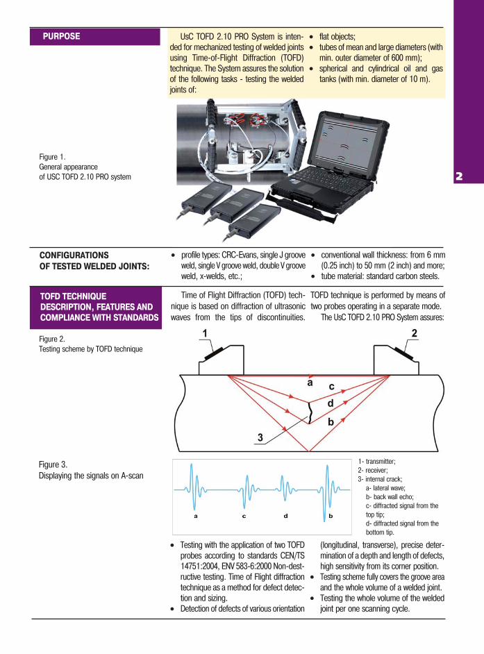
Figure 3.Displaying the signals on A�scan
• profile types: CRC�Evans, single J grooveweld, single V groove weld, double V grooveweld, x�welds, etc.;
• conventional wall thickness: from 6 mm(0.25 inch) to 50 mm (2 inch) and more;
• tube material: standard carbon steels.
Time of Flight Diffraction (TOFD) tech�nique is based on diffraction of ultrasonicwaves from the tips of discontinuities.
TOFD technique is performed by means oftwo probes operating in a separate mode.
The UsC TOFD 2.10 PRO System assures:
• Testing with the application of two TOFDprobes according to standards CEN/TS14751:2004, ENV 583�6:2000 Non�dest�ructive testing. Time of Flight diffractiontechnique as a method for defect detec�tion and sizing.
• Detection of defects of various orientation
(longitudinal, transverse), precise deter�mination of a depth and length of defects,high sensitivity from its corner position.
• Testing scheme fully covers the groove areaand the whole volume of a welded joint.
• Testing the whole volume of the weldedjoint per one scanning cycle.
1� transmitter;2� receiver;3� internal crack;
a� lateral wave;b� back wall echo;c� diffracted signal from the top tip;d� diffracted signal from the bottom tip.
Figure 2.Testing scheme by TOFD technique
Figure 1.General appearance of USC TOFD 2.10 PRO system 2

3
SOFTWARE
• selecting the test object geometry andsetting up its geometrical dimensions;
• selecting the type of test object material;
• selecting the type of a weld bevel andsetting up all geometrical dimensions.
• selecting the scanner;• setting up the scanner type: manual,
motor�operated;• setting up the spatial position of TOFD�
transducers pair relative to the origin ofthe coordinate system;
• using of up to 4 TOFD transducer pairs; • carrying out the encoder calibration.
• selecting the type of TOFD probes, TOFDwedges, setup of their parameters;
• setting up the PCS � the distance bet�ween the index points of TOFD trans�ducers and their shift relative to thewelded joint axis;
• calculation and graphic plotting of the
following parameters when using theTOFD Calculator:
— Spatial resolution ( R );— Scanning�surface dead zone ( Dds );— Backwall dead zone ( Ddw );— Locus curve;— Beam Spread.
Figure 4. Object The “Object” page ensures:
The “Scanner” page ensures:
The “TOFD setup” page ensures:
Figure 5. Scanner
Figure 6. TOFD setup
SYSTEM SOFTWARE
INCLUDES THE FOLLOWING
PAGES (MODULES):

4
Figure 7. TOFD calibration
The “TOFD calibration” page ensures:• setting up the testing parameters for TOFD;• carrying out the real�time TOFD cali�
bration or by saved data;• real�time check up of reflectors detec�
tion in calibration block;
• generating the parameters matrix ofcalibration block reflectors;
• saving the calibration results.
The “Data acquisition” page ensures:• data display in a form of A�Scan toge�
ther with TOFD�Scan during the testingprocess;
• carrying out the testing and data acqui�sition with an auto stop of a testing
mode by a distance predetermined bythe operator;
• displaying the current scanner position(the coordinate along the scanning path)and the scanning speed;
• data synchronization during the testing
process by lateral wave;• considering the scanning direction and
capability to perform confirming tes�ting of regions with insufficientacoustic coupling;
• saving the testing results.
Figure 8. Data acquisition
Figure 9. Data analysis
• discontinuities detected by TOFD shallbe characterized by at least:— their position in the object (X and Ycoordinates);— their length ( ΔX );
— their depth and height ( Z, ΔZ );— their type, limited to: “top�surfacebreaking”, “bottom�surface breaking” or“embedded”.
• generating the defect list and its saving.
The “Data analysis” page ensures:• review and analysis of saved data in a
form of А�Scans toge and TOFD�Scans;• quick and detailed analysis of testing
results while using two measuring gates(type: conventional, hyperbolic, hyper�bolic manual);

5
Shockproof industrial notebook/tablet with installed Microsoft Windows software
Couplant is supplied to the scanner with motorized pump and magnetic valve. Couplant feed control is carried out with regulating valve set on the scanner.
TOFD 2.10 PRO scanner is a com�pact, reliable and field�proven deviceallowing to achieve reliable and stableresults of scanning.
Magnetic wheels and spring�loadedprobe holders ensure the probe firmstability on the surface being the neces�sary condition for high�quality testing.Scanner can be easily manipulated andattached to ferromagnetic inspectionsurfaces.
The system may contain up to 4 data acquisition units UsC TOFD.Ultrasonic unit ensures data acquisition and transmission in real�time mode via
Ethernet interface to industrial notebook or tablet.Unit case is made of shock�proof material.
USC TOFD 2.10 PRO SYSTEM COMPOSITION
INDUSTRIAL NOTEBOOK
AND SOFTWARE
TOFD 2.10 PRO SCANNER
DATA ACQUISITION
UNIT USC TOFD
COUPLANT�FEED UNIT
USC TOFD UNIT SPECIFICATIONS
• Ultrasonic transducers connector _ _ _ _ _ _ _ _ _ _ _ _ _ _ _ _ _ _ _ _ _ _ _ _ _ _ _ _ _ _ _ _ _ _ _ _ _ _ _ _ _ _ _ _ _ _ _2 (Lemo)• A/D converter _ _ _ _ _ _ _ _ _ _ _ _ _ _ _ _ _ _ _ _ _ _ _ _ _ _ _ _ _ _ _ _ _ _ _ _ _ _ _ _ _ _ _ _ _ _ _ _ _ _ _ _ _ _10 bit (100 MHz)• Amplitude _ _ _ _ _ _ _ _ _ _ _ _ _ _ _ _ _ _ _ _ _ _ _ _ _ _ _ _ _ _ _ _ _ _ _ _ _ _ _ _ _ _ _ _ _ _ _ _ _ _ _ _ 120— 400 V (step 10 V) • Gain _ _ _ _ _ _ _ _ _ _ _ _ _ _ _ _ _ _ _ _ _ _ _ _ _ _ _ _ _ _ _ _ _ _ _ _ _ _ _ _ _ _ _ _ _ _ _ _ _ _ _ _ _ _ _ _ _ _ _ _ _up to 110 dB• Rectification _ _ _ _ _ _ _ _ _ _ _ _ _ _ _ _ _ _ _ _ _ _ _ _ _ _ _ _ _ _ _full wave, + half wave, � half wave and radio frequency• Bandwidth _ _ _ _ _ _ _ _ _ _ _ _ _ _ _ _ _ _ _ _ _ _ _ _ _ _ _ _ _ _ _ _ _ _ _ _ _ _ _ _ _ _ _ _ _ _ _ _ _ _ _ _ _ _ _ _ _ 0.2 � 27 MHz• Encoder _ _ _ _ _ _ _ _ _ _ _ _ _ _ _ _ _ _ _ _ _ _ _ _ _ _ _ _ _ _ _ _ _ _ _ _ _ _ _ _ _ _ _ _ _ _ _ _ _ _ _ _ _ _ _ 1� axis encoder line• PRF _ _ _ _ _ _ _ _ _ _ _ _ _ _ _ _ _ _ _ _ _ _ _ _ _ _ _ _ _ _ _ _ _ _ _ _ _ _ _ _ _ _ _ _ _ _ _ _ _ _ _ _ _ _ _ _ _ _ _ _ _ _15 � 8000 Hz• Real�time averaging _ _ _ _ _ _ _ _ _ _ _ _ _ _ _ _ _ _ _ _ _ _ _ _ _ _ _ _ _ _ _ _ _ _ _ _ _ _ _ _ _ _ _ _ _ _ _ _ _ _1, 2, 4, 8, 16, 32• Maximum scan velocity _ _ _ _ _ _ _ _ _ _ _ _ _ _ _ _ _ _ _ _ _ _ _ _ _ _ _ _ _ _ _ _ _ _ _ _ _ _ _ _ _ _ _ _ _ _ _ _ _ _ _ _ _100 m/s• Operating temperature range _ _ _ _ _ _ _ _ _ _ _ _ _ _ _ _ _ _ _ _ _ _ _ _ _ _ _ _ _ _ _ _ _ _ _ _from minus 20 0С to plus 50 0С
Figure 10.General appearance of USC TOFD 2.10 PRO SCANNER
The "Reports" page ensures:• Generating the reports according to the
requirements of Regulatory DocumentationCEN/TS 14751:2004, ENV 583�6:2000;
• Approval of report forms with the cus�tomer when necessary.The software is designed for ease of
use, flexibility and scalability, and is oriented
for a touchscreen operation.The user interface is optimized for the
accelerated learning process and improvingthe efficiency of use.
for system setup, data acquisition and analysis.

ULTRACON�SERVICE LLC P.O.Box 31, Kiev 04111, Ukraine, tel./fax: +38 044 531�37�27(26)
E�mail: [email protected] www.ndt.com.ua
®