us lift chair series om rev i jan10 3446 - easymedonline chair series 1-800-800-8586 (us)...
TRANSCRIPT

®
®
LIFT CHAIRSERIES
1-800-800-8586 (US) 1-888-570-1113 (Canada)
182 Susquehanna Avenue Exeter, PA 18643-2694
www.pridemobility.com

The symbols below are used throughout this owner's manual and on the product to identify warnings andimportant information. It is very important for you to read them and understand them completely.
WARNING! Indicates a potentially hazardous condition/situation. Failure to followdesignated procedures can cause either personal injury, component damage, ormalfunction. On the product, this icon is represented as a black symbol on a yellowtriangle with a black border.
MANDATORY! These actions should be performed as specified. Failure to performmandatory actions can cause personal injury and/or equipment damage. On theproduct, this icon is represented as a white symbol on a blue dot with a whiteborder.
PROHIBITED! These actions are prohibited. These actions should not be performedat any time or in any circumstances. Performing a prohibited action can causepersonal injury and/or equipment damage. On the product, this icon is representedas a black symbol with a red circle and red slash.
SAFETY GUIDELINESLIFT CHAIR SERIES
NOTE: This owner’s manual is compiled from the latest specifications and product informationavailable at the time of publication. We reserve the right to make changes as they become nec-essary. Any changes to our products may cause slight variations between the illustrations andexplanations in this manual and the product you have purchased. The latest/current version ofthis manual is available on our website.
Copyright © 2010Pride Mobility Products Corp.INFMANU3446/Rev I/January 2010
Please fill out the following information for quick reference:
Pride Provider:
Address:
Phone Number:
Purchase Date: Serial Number:
088 609 661
Lift Chair Series www.pridemobility.com 3
LIFT CHAIR SERIESLABEL INFORMATION
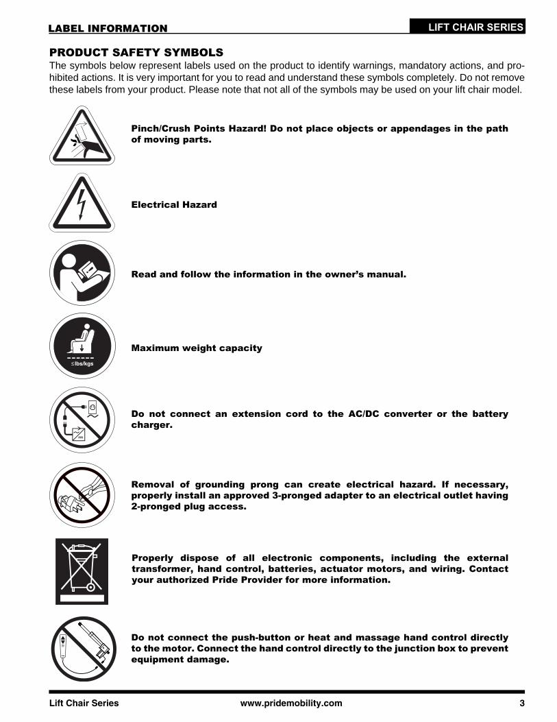
PRODUCT SAFETY SYMBOLSThe symbols below represent labels used on the product to identify warnings, mandatory actions, and pro-hibited actions. It is very important for you to read and understand these symbols completely. Do not removethese labels from your product. Please note that not all of the symbols may be used on your lift chair model.
Pinch/Crush Points Hazard! Do not place objects or appendages in the pathof moving parts.
Read and follow the information in the owner’s manual.
Maximum weight capacity
Do not connect an extension cord to the AC/DC converter or the batterycharger.
Electrical Hazard
Removal of grounding prong can create electrical hazard. If necessary,properly install an approved 3-pronged adapter to an electrical outlet having2-pronged plug access.
Properly dispose of all electronic components, including the externaltransformer, hand control, batteries, actuator motors, and wiring. Contactyour authorized Pride Provider for more information.
Do not connect the push-button or heat and massage hand control directlyto the motor. Connect the hand control directly to the junction box to preventequipment damage.
4 www.pridemobility.com Lift Chair Series
LIFT CHAIR SERIES LABEL INFORMATION
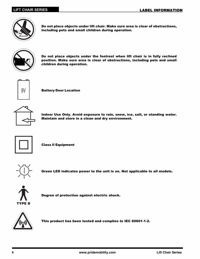
Battery Door Location
Green LED indicates power to the unit is on. Not applicable to all models.
Indoor Use Only. Avoid exposure to rain, snow, ice, salt, or standing water.Maintain and store in a clean and dry environment.
Class II Equipment
Do not place objects under lift chair. Make sure area is clear of obstructions,including pets and small children during operation.
Degree of protection against electric shock.
This product has been tested and complies to IEC 60601-1-2.
Do not place objects under the footrest when lift chair is in fully reclinedposition. Make sure area is clear of obstructions, including pets and smallchildren during operation.
Lift Chair Series www.pridemobility.com 5
LIFT CHAIR SERIESTABLE OF CONTENTS
SAFETY GUIDELINES .......................................................................................... 2
LABEL INFORMATION ......................................................................................... 3
I. INTRODUCTION................................................................................................ 6SAFETY ........................................................................................................................................................................6PURCHASER’S AGREEMENT.....................................................................................................................................6INFORMATION EXCHANGE........................................................................................................................................6
II. GENERAL GUIDELINES................................................................................... 7MODIFICATIONS .........................................................................................................................................................7WEIGHT LIMITATIONS ................................................................................................................................................7PINCH/CRUSH HAZARDS...........................................................................................................................................7DEGREE OF PROTECTION/MODE OF OPERATION ................................................................................................7STORAGE AND OPERATION TEMPERATURES .......................................................................................................7EMI/RFI .........................................................................................................................................................................8SHIPPING AND DELIVERY .........................................................................................................................................8MOTOR VEHICLE TRANSPORT .................................................................................................................................8
III. YOUR LIFT CHAIR.......................................................................................... 9BODY COMPONENTS .................................................................................................................................................9ELECTRICAL COMPONENTS ...................................................................................................................................11
IV. ASSEMBLY/DISASSEMBLY .......................................................................... 12LIFT CHAIR SETUP ...................................................................................................................................................12LIFT CHAIR PLACEMENT .........................................................................................................................................14BATTERY INSTALLATION.........................................................................................................................................14LIFT CHAIR DISASSEMBLY ......................................................................................................................................15
V. OPERATION................................................................................................... 16OPERATION PRECAUTIONS....................................................................................................................................16HAND CONTROL OPERATION .................................................................................................................................16
VI. TROUBLESHOOTING ................................................................................... 22MOTOR TIMING .........................................................................................................................................................22FREQUENTLY ASKED QUESTIONS.........................................................................................................................23
VII. CARE AND MAINTENANCE......................................................................... 24FABRIC CARE............................................................................................................................................................24ELECTRONICS CARE ...............................................................................................................................................24DISPOSAL AND RECYCLING ...................................................................................................................................24
VIII. WARRANTY................................................................................................ 25
APPENDIX.......................................................................................................... 27

6 www.pridemobility.com Lift Chair Series
LIFT CHAIR SERIES
SAFETYWELCOME to Pride Mobility Products Corporation (Pride). The product you have purchasedcombines state-of-the-art components with safety, comfort, and styling in mind. We are confi-dent the design features will provide you with the conveniences you expect during your dailyactivities. Understanding how to safely operate and care for this product should bring you yearsof trouble-free operation and service.
Read and follow all instructions, warnings, and notes in this manual and all other accompanying literaturebefore attempting to operate this product for the first time. In addition, your safety depends upon you, as wellas your provider, caretaker, or healthcare professional in using good judgment.
If there is any information in this manual which you do not understand, or if you require additional assistancefor setup or operation, please contact your authorized Pride Provider. Failure to follow the instructions,warnings, and notes in this manual and those located on your Pride product can result in personalinjury or product damage and will void Pride’s product warranty.
PURCHASER’S AGREEMENT By accepting delivery of this product, you promise that you will not change, alter, or modify this product orremove or render inoperable or unsafe any guards, shields, or other safety features of this product; fail,refuse, or neglect to install any retrofit kits from time to time provided by Pride to enhance or preserve thesafe use of this product.
INFORMATION EXCHANGEWe want to hear your questions, comments, and suggestions about this manual. We would also like to hearabout the safety and reliability of your new lift chair, and about the service you received from your authorizedPride Provider. Please notify us of any change of address, so we can keep you apprised of important infor-mation about safety, new products, and new options that can increase your ability to use and enjoy your liftchair. Please feel free to contact us at the address below:
USA: Canada:Pride Mobility Products Corporation Pride Mobility Products CompanyAttn.: Customer Care Department 380 Vansickle Road Unit 350182 Susquehanna Ave. St. Catharines, Ontario L2R 6P7Exeter, PA 18643-2694 [email protected]
NOTE: If you ever lose or misplace your product registration card or your copy of this manual,contact us and we will be glad to send you a new one immediately.
I. INTRODUCTION
LIFT CHAIR SERIESII. GENERAL GUIDELINES
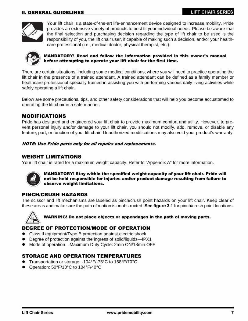
Your lift chair is a state-of-the-art life-enhancement device designed to increase mobility. Prideprovides an extensive variety of products to best fit your individual needs. Please be aware thatthe final selection and purchasing decision regarding the type of lift chair to be used is theresponsibility of you, the lift chair user, if capable of making such a decision, and/or your health-care professional (i.e., medical doctor, physical therapist, etc.).
MANDATORY! Read and follow the information provided in this owner’s manualbefore attempting to operate your lift chair for the first time.
There are certain situations, including some medical conditions, where you will need to practice operating thelift chair in the presence of a trained attendant. A trained attendant can be defined as a family member orhealthcare professional specially trained in assisting you with performing various daily living activities whilesafely operating a lift chair.
Below are some precautions, tips, and other safety considerations that will help you become accustomed tooperating the lift chair in a safe manner.
MODIFICATIONSPride has designed and engineered your lift chair to provide maximum comfort and utility. However, to pre-vent personal injury and/or damage to your lift chair, you should not modify, add, remove, or disable anyfeature, part, or function of your lift chair. Unauthorized modifications may also void your product’s warranty.
NOTE: Use Pride parts only for all repairs and replacements.
WEIGHT LIMITATIONSYour lift chair is rated for a maximum weight capacity. Refer to “Appendix A” for more information.
MANDATORY! Stay within the specified weight capacity of your lift chair. Pride willnot be held responsible for injuries and/or product damage resulting from failure toobserve weight limitations.
PINCH/CRUSH HAZARDSThe scissor and lift mechanisms are labeled as pinch/crush point hazards on your lift chair. Keep clear ofthese areas and make sure the path of motion is unobstructed. See figure 3.1 for pinch/crush point locations.
WARNING! Do not place objects or appendages in the path of moving parts.
DEGREE OF PROTECTION/MODE OF OPERATIONClass II equipment/Type B protection against electric shockDegree of protection against the ingress of solid/liquids—IPX1Mode of operation—Maximum Duty Cycle: 2min ON/18min OFF
STORAGE AND OPERATION TEMPERATURESTransportation or storage: -104°F/-75°C to 158°F/70°COperation: 50°F/10°C to 104°F/40°C
Lift Chair Series www.pridemobility.com 7
LIFT CHAIR SERIES II. GENERAL GUIDELINES
ELECTROMAGNETIC AND RADIO FREQUENCY INTERFERENCE (EMI/RFI)
WARNING! Laboratory tests have shown that electromagnetic and radio frequencywaves can have an adverse affect on the performance of electrically-powereddevices, such as lift chairs.
Electromagnetic and Radio Frequency Interference can come from sources such as cellular phones, mobiletwo-way radios (such as walkie-talkies), radio stations, TV stations, amateur radio (HAM) transmitters, wire-less computer links, microwave signals, paging transmitters, and medium-range mobile transceivers used byemergency vehicles. In some cases, these waves can cause unintended movement or damage to the controlsystem of electrically-powered devices. The lift chair user can help prevent electromagnetic interference bymaintaining a minimum distance between portable and mobile RF communications equipment. It is recom-mended that at lest 9 feet (3 meters) of distance be maintained between the lift chair and any handheldequipment emitting 10 W or more of output power. Refer to the manufacturer’s literature for the handhelddevice to determine the maximum output of that device.
Every electrically-powered device has an immunity (or resistance) to EMI. The higher the immunity level, thegreater the protection against EMI. Per EMC standards, this product has passed immunity testing and is ratedas a Group 1, Class B product, meaning the lift chair uses RF energy only for its internal function. Therefore,its RF emissions are very low and are not likely to cause any interference in nearby electronic equipment,making the lift chair suitable for use in all establishments, including domestic establishments and hospitals.
WARNING! Be aware that cell phones, two-way radios, laptops, and other types ofradio transmitters may cause unintended movement of your electrically-powereddevice due to EMI. Exercise caution when using any of these items while operatingyour lift chair.
WARNING! The addition of accessories or components to the lift chair can increasethe susceptibility of the chair to EMI. Do not modify your lift chair in any way notauthorized by Pride.
WARNING! Your lift chair itself can disturb the performance of other electricaldevices located nearby, such as alarm systems.
NOTE: If unintended motion occurs, discontinue use of the lift chair. Contact Pride to report theincident.
SHIPPING AND DELIVERYBefore using your lift chair, make sure your delivery is complete as some components may be individuallypackaged. If you do not receive a complete delivery, please contact your authorized Pride Provider immedi-ately. Where damage has occurred during transport, either to the packaging or content, please contact thedelivery company responsible.
MOTOR VEHICLE TRANSPORTIf you will be transporting your lift chair in a motor vehicle, individual components (external transformer, etc.)should be secured against slipping. The lift chair itself must also be secured against slipping (a possiblehazard during vehicle braking).
8 www.pridemobility.com Lift Chair Series
Lift Chair Series www.pridemobility.com 9
LIFT CHAIR SERIES
QUICK-RELEASE CONNECTOR
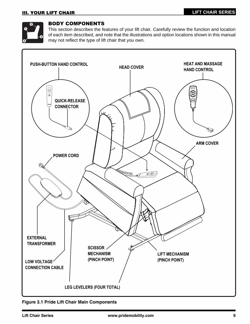
BODY COMPONENTSThis section describes the features of your lift chair. Carefully review the function and locationof each item described, and note that the illustrations and option locations shown in this manualmay not reflect the type of lift chair that you own.
III. YOUR LIFT CHAIR
Figure 3.1 Pride Lift Chair Main Components
HEAD COVERPUSH-BUTTON HAND CONTROL
ARM COVER
EXTERNAL TRANSFORMER
LIFT MECHANISM (PINCH POINT)
LEG LEVELERS (FOUR TOTAL)
SCISSOR MECHANISM (PINCH POINT)
POWER CORD
LOW VOLTAGE CONNECTION CABLE
HEAT AND MASSAGE HAND CONTROL
10 www.pridemobility.com Lift Chair Series
LIFT CHAIR SERIES III. YOUR LIFT CHAIR
Removable Back Pad: Attaches to the lift chair withreusable fasteners to enable the use of the bedoption on some models and to make servicing thechair more convenient.
Removable Chaise Pad: Attaches to the lift chairwith reusable fasteners to make servicing the chairmore convenient.
NOTE: The lift chair must be in the recline posi-tion in order to remove or attach the back pad,chaise pad, or bed option mattress.
NOTE: The LL670 bed option consists of a mat-tress, bedsheet, strap, and storage bag. Afterremoving the mattress, it is recommended thatyou store it in the bag provided.
NOTE: If your lift chair is equipped with a removable back and/or chaise pad and has the heatand massage option, disconnect the heat and massage cords, then remove the back pad and/orchaise pad. Refer to “Appendix F,” “Appendix G,” or “Appendix H” for the heat and massageelectrical diagrams.
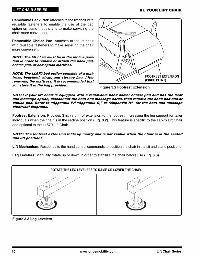
Footrest Extension: Provides 3 in. (8 cm) of extension to the footrest, increasing the leg support for tallerindividuals when the chair is in the recline position (Fig. 3.2). This feature is specific to the LL575 Lift Chairand optional to the LL570 Lift Chair.
NOTE: The footrest extension folds up neatly and is not visible when the chair is in the seatedand lift positions.
Lift Mechanism: Responds to the hand control commands to position the chair in the sit and stand positions.
Leg Levelers: Manually rotate up or down in order to stabilize the chair before use (Fig. 3.3).
Figure 3.2 Footrest Extension
Figure 3.3 Leg Levelers
ROTATE THE LEG LEVELERS TO RAISE OR LOWER THE CHAIR.
FOOTREST EXTENSION(PINCH POINT)
LIFT CHAIR SERIESIII. YOUR LIFT CHAIR
Figure 3.4 Scissor Mechanism
SCISSORMECHANISMS(PINCH POINT)
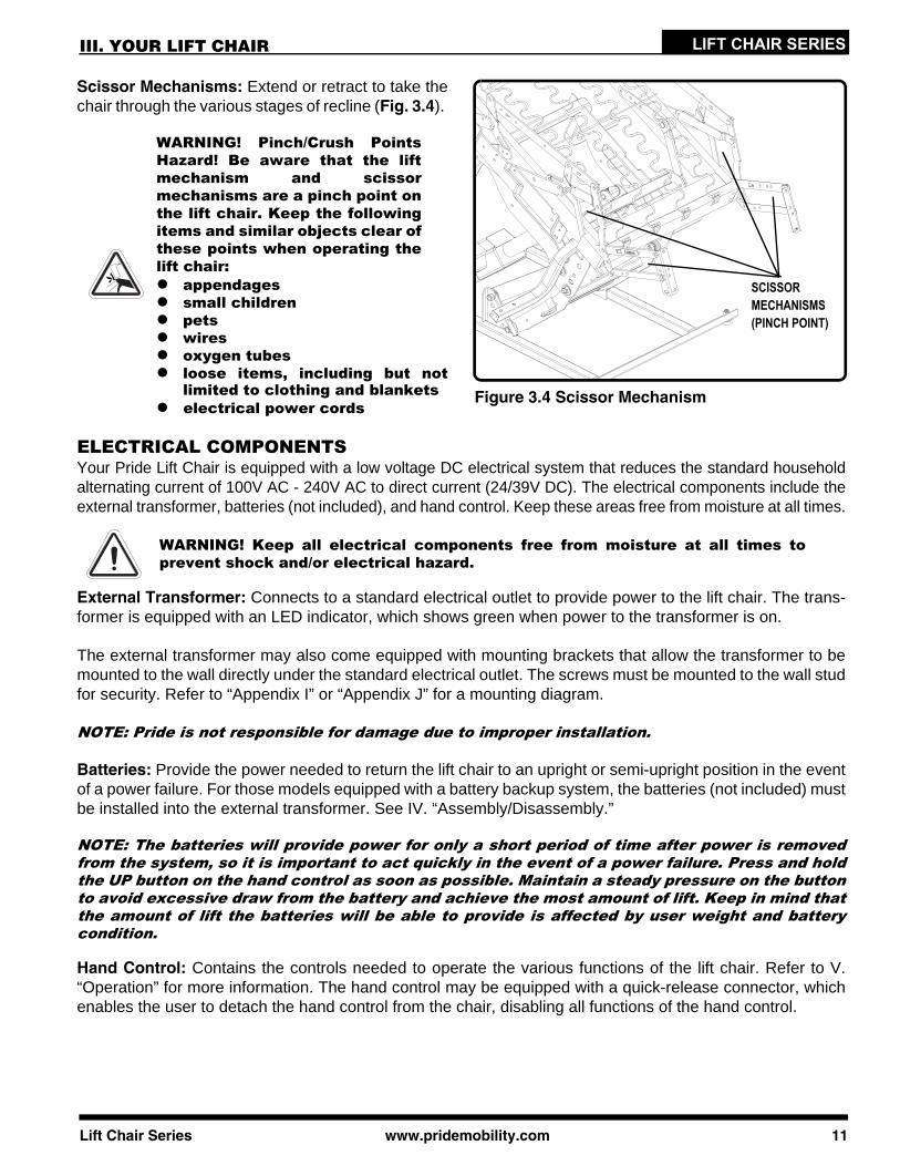
Scissor Mechanisms: Extend or retract to take thechair through the various stages of recline (Fig. 3.4).
WARNING! Pinch/Crush PointsHazard! Be aware that the liftmechanism and scissormechanisms are a pinch point onthe lift chair. Keep the followingitems and similar objects clear ofthese points when operating thelift chair:
appendagessmall childrenpetswiresoxygen tubesloose items, including but notlimited to clothing and blankets
electrical power cords
ELECTRICAL COMPONENTSYour Pride Lift Chair is equipped with a low voltage DC electrical system that reduces the standard householdalternating current of 100V AC - 240V AC to direct current (24/39V DC). The electrical components include theexternal transformer, batteries (not included), and hand control. Keep these areas free from moisture at all times.
External Transformer: Connects to a standard electrical outlet to provide power to the lift chair. The trans-former is equipped with an LED indicator, which shows green when power to the transformer is on.
The external transformer may also come equipped with mounting brackets that allow the transformer to bemounted to the wall directly under the standard electrical outlet. The screws must be mounted to the wall studfor security. Refer to “Appendix I” or “Appendix J” for a mounting diagram.
NOTE: Pride is not responsible for damage due to improper installation.
Batteries: Provide the power needed to return the lift chair to an upright or semi-upright position in the eventof a power failure. For those models equipped with a battery backup system, the batteries (not included) mustbe installed into the external transformer. See IV. “Assembly/Disassembly.”
NOTE: The batteries will provide power for only a short period of time after power is removedfrom the system, so it is important to act quickly in the event of a power failure. Press and holdthe UP button on the hand control as soon as possible. Maintain a steady pressure on the buttonto avoid excessive draw from the battery and achieve the most amount of lift. Keep in mind thatthe amount of lift the batteries will be able to provide is affected by user weight and batterycondition.
Hand Control: Contains the controls needed to operate the various functions of the lift chair. Refer to V.“Operation” for more information. The hand control may be equipped with a quick-release connector, whichenables the user to detach the hand control from the chair, disabling all functions of the hand control.
WARNING! Keep all electrical components free from moisture at all times toprevent shock and/or electrical hazard.
Lift Chair Series www.pridemobility.com 11
LIFT CHAIR SERIES IV. ASSEMBLY/DISASSEMBLY
Your lift chair may require some assembly before initial use. It may also require disassembly tomake servicing the chair more convenient. If your lift chair is a Knock-Down (KD) model, followthe instructions in “Lift Chair Setup.” If your lift chair is not a KD model, proceed to “Lift ChairPlacement.”
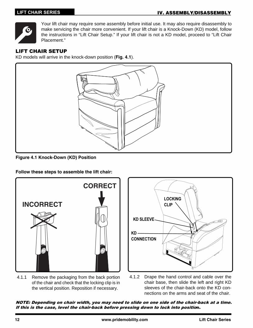
LIFT CHAIR SETUPKD models will arrive in the knock-down position (Fig. 4.1).
Figure 4.1 Knock-Down (KD) Position
Follow these steps to assemble the lift chair:
12 www.pridemobility.com Lift Chair Series
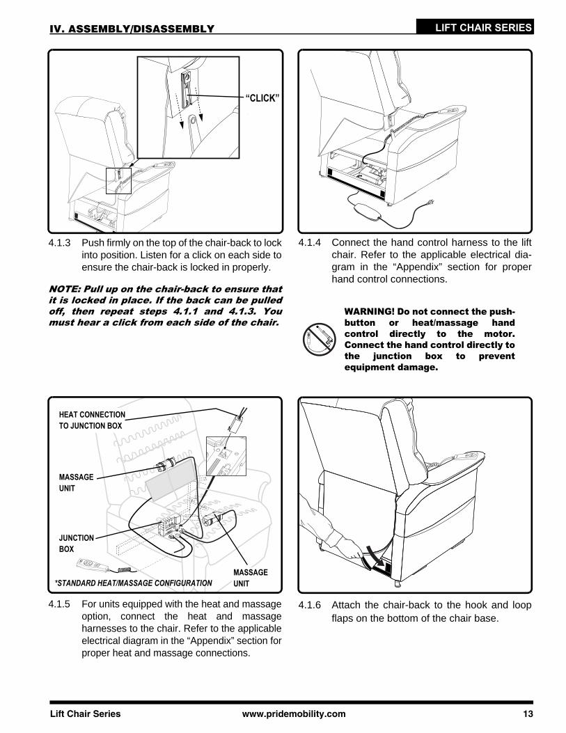
LOCKING CLIP
KD SLEEVE
KD CONNECTION
4.1.2 Drape the hand control and cable over thechair base, then slide the left and right KDsleeves of the chair-back onto the KD con-nections on the arms and seat of the chair.
4.1.1 Remove the packaging from the back portionof the chair and check that the locking clip is inthe vertical position. Reposition if necessary.
NOTE: Depending on chair width, you may need to slide on one side of the chair-back at a time.If this is the case, level the chair-back before pressing down to lock into position.
LIFT CHAIR SERIESIV. ASSEMBLY/DISASSEMBLY
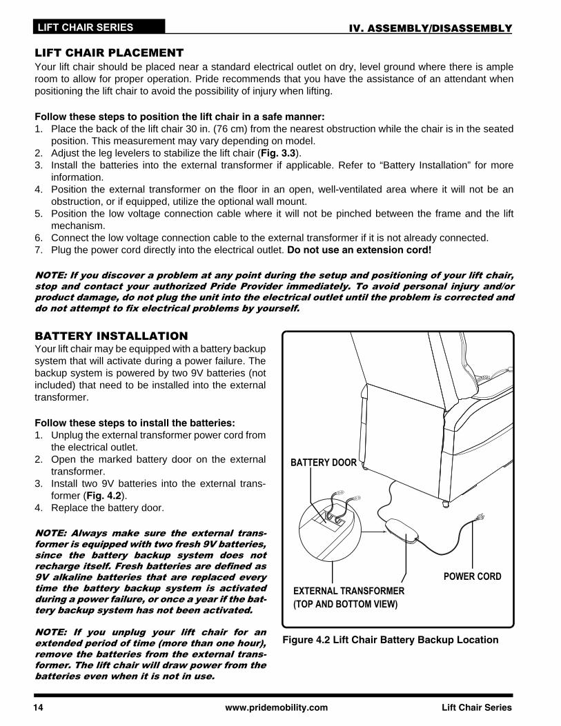
“CLICK”
4.1.3 Push firmly on the top of the chair-back to lockinto position. Listen for a click on each side toensure the chair-back is locked in properly.
Lift Chair Series www.pridem
MASSAGE UNIT
MASSAGE UNIT
JUNCTION BOX
HEAT CONNECTIONTO JUNCTION BOX
NOTE: Pull up on the chair-back to ensure thatit is locked in place. If the back can be pulledoff, then repeat steps 4.1.1 and 4.1.3. Youmust hear a click from each side of the chair.
*STANDARD HEAT/MASSAGE CONFIGURATION
4.1.4 Connect the hand control harness to the liftchair. Refer to the applicable electrical dia-gram in the “Appendix” section for properhand control connections.
WARNING! Do not connect the push-button or heat/massage handcontrol directly to the motor.Connect the hand control directly tothe junction box to preventequipment damage.
4.1.5 For units equipped with the heat and massageoption, connect the heat and massageharnesses to the chair. Refer to the applicableelectrical diagram in the “Appendix” section forproper heat and massage connections.
4.1.6 Attach the chair-back to the hook and loopflaps on the bottom of the chair base.
obility.com 13
LIFT CHAIR SERIES IV. ASSEMBLY/DISASSEMBLY
LIFT CHAIR PLACEMENTYour lift chair should be placed near a standard electrical outlet on dry, level ground where there is ampleroom to allow for proper operation. Pride recommends that you have the assistance of an attendant whenpositioning the lift chair to avoid the possibility of injury when lifting.
Follow these steps to position the lift chair in a safe manner:1. Place the back of the lift chair 30 in. (76 cm) from the nearest obstruction while the chair is in the seated
position. This measurement may vary depending on model.2. Adjust the leg levelers to stabilize the lift chair (Fig. 3.3).3. Install the batteries into the external transformer if applicable. Refer to “Battery Installation” for more
information.4. Position the external transformer on the floor in an open, well-ventilated area where it will not be an
obstruction, or if equipped, utilize the optional wall mount.5. Position the low voltage connection cable where it will not be pinched between the frame and the lift
mechanism.6. Connect the low voltage connection cable to the external transformer if it is not already connected.7. Plug the power cord directly into the electrical outlet. Do not use an extension cord!
NOTE: If you discover a problem at any point during the setup and positioning of your lift chair,stop and contact your authorized Pride Provider immediately. To avoid personal injury and/orproduct damage, do not plug the unit into the electrical outlet until the problem is corrected anddo not attempt to fix electrical problems by yourself.
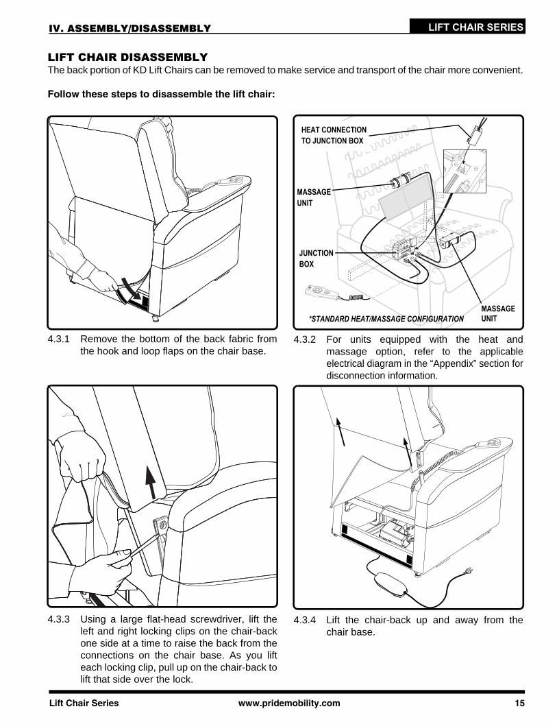
EXTERNAL TRANSFORMER (TOP AND BOTTOM VIEW)
BATTERY DOOR
POWER CORD
Figure 4.2 Lift Chair Battery Backup Location
BATTERY INSTALLATIONYour lift chair may be equipped with a battery backupsystem that will activate during a power failure. Thebackup system is powered by two 9V batteries (notincluded) that need to be installed into the externaltransformer.
Follow these steps to install the batteries:1. Unplug the external transformer power cord from
the electrical outlet.2. Open the marked battery door on the external
transformer.3. Install two 9V batteries into the external trans-
former (Fig. 4.2).4. Replace the battery door.
NOTE: Always make sure the external trans-former is equipped with two fresh 9V batteries,since the battery backup system does notrecharge itself. Fresh batteries are defined as9V alkaline batteries that are replaced everytime the battery backup system is activatedduring a power failure, or once a year if the bat-tery backup system has not been activated.
NOTE: If you unplug your lift chair for anextended period of time (more than one hour),remove the batteries from the external trans-former. The lift chair will draw power from thebatteries even when it is not in use.
14 www.pridemobility.com Lift Chair Series
LIFT CHAIR SERIESIV. ASSEMBLY/DISASSEMBLY
LIFT CHAIR DISASSEMBLYThe back portion of KD Lift Chairs can be removed to make service and transport of the chair more convenient.
Follow these steps to disassemble the lift chair:
HEAT CONNECTIONTO JUNCTION BOX
*STANDARD HEAT/MASSAGE CONFIGURATION
MASSAGE UNIT
MASSAGE UNIT
JUNCTION BOX
4.3.1 Remove the bottom of the back fabric fromthe hook and loop flaps on the chair base.
Lift Chair Series www.pridem
4.3.2 For units equipped with the heat andmassage option, refer to the applicableelectrical diagram in the “Appendix” section fordisconnection information.
4.3.3 Using a large flat-head screwdriver, lift theleft and right locking clips on the chair-backone side at a time to raise the back from theconnections on the chair base. As you lifteach locking clip, pull up on the chair-back tolift that side over the lock.
4.3.4 Lift the chair-back up and away from thechair base.
obility.com 15
16 www.pridemobility.com Lift Chair Series
LIFT CHAIR SERIES
OPERATION PRECAUTIONSThere are certain precautions that should be taken during the operation of your lift chair. Readand follow these precautions carefully in order to ensure safe lift chair operation and to preventinjury and/or product damage.
Plug the power cord directly into the electrical outlet. Do not use an extension cord!Do not place anything (for example, a drinking glass) on top of or near the external transformer.If the external transformer box or hand control requires cleaning, unplug the power cord from the electricaloutlet and use a clean, dry cloth or lightly dampened cloth. Allow ample drying time before plugging thepower cord back into the electrical outlet.Periodically check the hand control and all power cords for visible damage.Keep the hand control away from all heated surfaces.Ensure the hand control is out of the way before sitting in the chair.Keep children and pets away from all moving parts while operating the lift chair.Do not allow children to play on or operate the lift chair. Only the intended user should operate the lift chair.Keep the hand control locked or utilize the quick-disconnect feature on the standard hand control whenthe lift chair is not in use to prevent unintended operation of the chair.Avoid pinch points, such as the lift and scissor mechanisms. Keep hands and feet clear of these areas.Always leave the lift chair in an upright and closed position when not in use.Do not sit or stand on the footrest.Do not “drop” into the lift chair when sitting if it is in a partially raised position.
PROHIBITED! Do not place objects under the lift chair. Make sure area is clear ofobstructions, including pets and small children during operation.
WARNING! Prevent the risk of electrical shock, fire, falls, and/or being pinched.Follow all instructions and precautions provided.
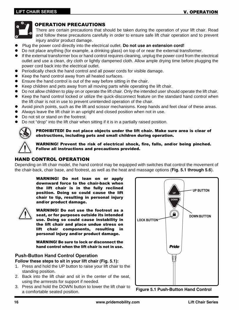
HAND CONTROL OPERATIONDepending on lift chair model, the hand control may be equipped with switches that control the movement ofthe chair-back, chair base, and footrest, as well as the heat and massage options (Fig. 5.1 through 5.6).
V. OPERATION
Figure 5.1 Push-Button Hand Control
LOCK BUTTONDOWN BUTTON
UP BUTTON
WARNING! Do not lean on or applydownward force to the chair-back whenthe lift chair is in the fully reclinedposition. Doing so could cause the liftchair to tip, resulting in personal injuryand/or product damage.
WARNING! Do not use the footrest as aseat, or for purposes outside its intendeduse. Doing so could cause instability inthe lift chair and place undue stress onlift chair components, resulting inpersonal injury and/or product damage.
WARNING! Be sure to lock or disconnect thehand control when the lift chair is not in use.
Push-Button Hand Control OperationFollow these steps to sit in your lift chair (Fig. 5.1):1. Press and hold the UP button to raise your lift chair to the
standing position.2. Back into the lift chair and sit in the center of the seat,
using the armrests for support if needed.3. Press and hold the DOWN button to lower the lift chair to
a comfortable seated position.
Lift Chair Series www.pridemobility.com 17
LIFT CHAIR SERIESV. OPERATION
Follow these steps to recline your lift chair from the seated position (Fig. 5.1):1. Press and hold the DOWN button until comfortably reclined.2. Press and hold the UP button to return to an upright, seated position. Release the button when the lift chair
reaches a comfortable seated position.
Follow these steps to stand up from your lift chair (Fig. 5.1):1. Press and hold the UP button to raise your lift chair.2. Release the button when the lift chair reaches a height where you can stand up comfortably.
Follow these steps to activate/deactivate the lock feature (Fig. 5.1):1. Press and hold the LOCK button for approximately 4 seconds to lock the hand control. 2. Press and hold the LOCK button for approximately 4 seconds to unlock the hand control.
NOTE: The lock button will display a red illumination to indicate when the chair is in lock mode.
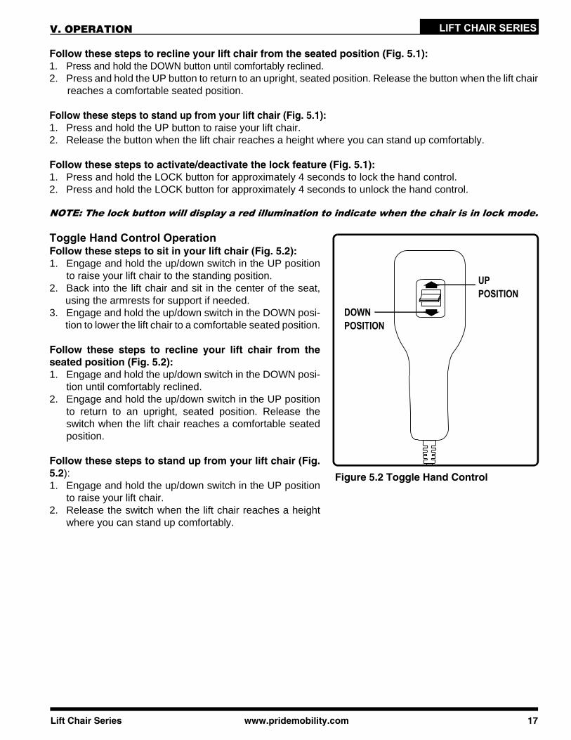
UP POSITION
DOWN POSITION
Figure 5.2 Toggle Hand Control
Toggle Hand Control OperationFollow these steps to sit in your lift chair (Fig. 5.2):1. Engage and hold the up/down switch in the UP position
to raise your lift chair to the standing position.2. Back into the lift chair and sit in the center of the seat,
using the armrests for support if needed.3. Engage and hold the up/down switch in the DOWN posi-
tion to lower the lift chair to a comfortable seated position.
Follow these steps to recline your lift chair from theseated position (Fig. 5.2):1. Engage and hold the up/down switch in the DOWN posi-
tion until comfortably reclined.2. Engage and hold the up/down switch in the UP position
to return to an upright, seated position. Release theswitch when the lift chair reaches a comfortable seatedposition.
Follow these steps to stand up from your lift chair (Fig.5.2):1. Engage and hold the up/down switch in the UP position
to raise your lift chair.2. Release the switch when the lift chair reaches a height
where you can stand up comfortably.
18 www.pridemobility.com Lift Chair Series
LIFT CHAIR SERIES
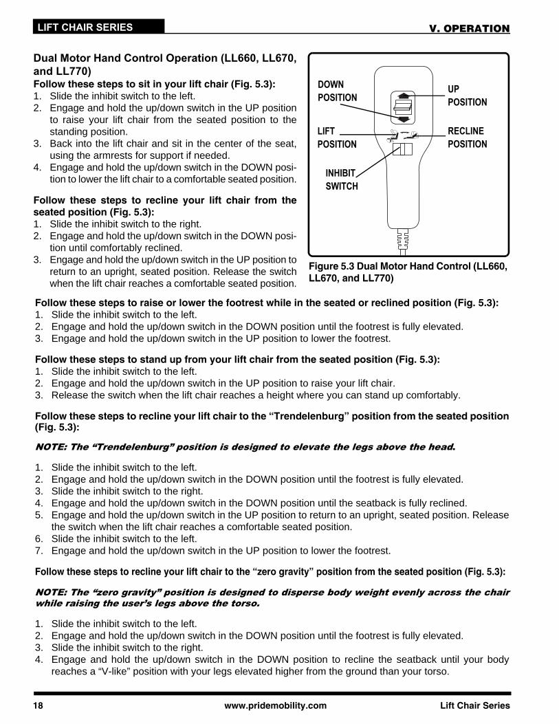
RECLINE POSITION
V. OPERATION
Figure 5.3 Dual Motor Hand Control (LL660,LL670, and LL770)
DOWN POSITION
INHIBIT SWITCH
Dual Motor Hand Control Operation (LL660, LL670,and LL770)Follow these steps to sit in your lift chair (Fig. 5.3):1. Slide the inhibit switch to the left. 2. Engage and hold the up/down switch in the UP position
to raise your lift chair from the seated position to thestanding position.
3. Back into the lift chair and sit in the center of the seat,using the armrests for support if needed.
4. Engage and hold the up/down switch in the DOWN posi-tion to lower the lift chair to a comfortable seated position.
Follow these steps to recline your lift chair from theseated position (Fig. 5.3):1. Slide the inhibit switch to the right.2. Engage and hold the up/down switch in the DOWN posi-
tion until comfortably reclined.3. Engage and hold the up/down switch in the UP position to
return to an upright, seated position. Release the switchwhen the lift chair reaches a comfortable seated position.
UP POSITION
Follow these steps to raise or lower the footrest while in the seated or reclined position (Fig. 5.3):1. Slide the inhibit switch to the left.2. Engage and hold the up/down switch in the DOWN position until the footrest is fully elevated.3. Engage and hold the up/down switch in the UP position to lower the footrest.
Follow these steps to stand up from your lift chair from the seated position (Fig. 5.3):1. Slide the inhibit switch to the left.2. Engage and hold the up/down switch in the UP position to raise your lift chair.3. Release the switch when the lift chair reaches a height where you can stand up comfortably.
Follow these steps to recline your lift chair to the “Trendelenburg” position from the seated position(Fig. 5.3):
NOTE: The “Trendelenburg” position is designed to elevate the legs above the head.
1. Slide the inhibit switch to the left.2. Engage and hold the up/down switch in the DOWN position until the footrest is fully elevated.3. Slide the inhibit switch to the right.4. Engage and hold the up/down switch in the DOWN position until the seatback is fully reclined.5. Engage and hold the up/down switch in the UP position to return to an upright, seated position. Release
the switch when the lift chair reaches a comfortable seated position.6. Slide the inhibit switch to the left.7. Engage and hold the up/down switch in the UP position to lower the footrest.
Follow these steps to recline your lift chair to the “zero gravity” position from the seated position (Fig. 5.3):
NOTE: The “zero gravity” position is designed to disperse body weight evenly across the chairwhile raising the user’s legs above the torso.
1. Slide the inhibit switch to the left.2. Engage and hold the up/down switch in the DOWN position until the footrest is fully elevated.3. Slide the inhibit switch to the right.4. Engage and hold the up/down switch in the DOWN position to recline the seatback until your body
reaches a “V-like” position with your legs elevated higher from the ground than your torso.
LIFT POSITION
Lift Chair Series www.pridemobility.com 19
LIFT CHAIR SERIES
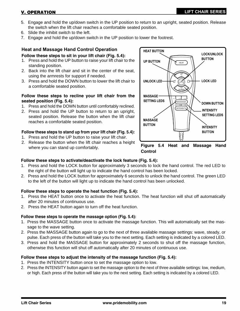
Figure 5.4 Heat and Massage HandControl
HEAT BUTTON
UP BUTTON
UNLOCK LED
LOCK/UNLOCK BUTTON
LOCK LED
DOWN BUTTON
MASSAGE SETTING LEDS
MASSAGE BUTTON INTENSITY
BUTTON
INTENSITY SETTING LEDS
Heat and Massage Hand Control OperationFollow these steps to sit in your lift chair (Fig. 5.4):1. Press and hold the UP button to raise your lift chair to the
standing position.2. Back into the lift chair and sit in the center of the seat,
using the armrests for support if needed.3. Press and hold the DOWN button to lower the lift chair to
a comfortable seated position.
Follow these steps to recline your lift chair from theseated position (Fig. 5.4):1. Press and hold the DOWN button until comfortably reclined.2. Press and hold the UP button to return to an upright,
seated position. Release the button when the lift chairreaches a comfortable seated position.
Follow these steps to stand up from your lift chair (Fig. 5.4):1. Press and hold the UP button to raise your lift chair.2. Release the button when the lift chair reaches a height
where you can stand up comfortably.
Follow these steps to activate/deactivate the lock feature (Fig. 5.4):1. Press and hold the LOCK button for approximately 3 seconds to lock the hand control. The red LED to
the right of the button will light up to indicate the hand control has been locked.2. Press and hold the LOCK button for approximately 6 seconds to unlock the hand control. The green LED
to the left of the button will light up to indicate the hand control has been unlocked.
Follow these steps to operate the heat function (Fig. 5.4): 1. Press the HEAT button once to activate the heat function. The heat function will shut off automatically
after 20 minutes of continuous use.2. Press the HEAT button again to turn off the heat function.
Follow these steps to operate the massage option (Fig. 5.4):1. Press the MASSAGE button once to activate the massage function. This will automatically set the mas-
sage to the wave setting.2. Press the MASSAGE button again to go to the next of three available massage settings: wave, steady, or
pulse. Each press of the button will take you to the next setting. Each setting is indicated by a colored LED.3. Press and hold the MASSAGE button for approximately 2 seconds to shut off the massage function,
otherwise this function will shut off automatically after 20 minutes of continuous use.
Follow these steps to adjust the intensity of the massage function (Fig. 5.4):1. Press the INTENSITY button once to set the massage option to low.2. Press the INTENSITY button again to set the massage option to the next of three available settings: low, medium,
or high. Each press of the button will take you to the next setting. Each setting is indicated by a colored LED.
5. Engage and hold the up/down switch in the UP position to return to an upright, seated position. Releasethe switch when the lift chair reaches a comfortable seated position.
6. Slide the inhibit switch to the left.7. Engage and hold the up/down switch in the UP position to lower the footrest.
V. OPERATION
20 www.pridemobility.com Lift Chair Series
LIFT CHAIR SERIES V. OPERATION
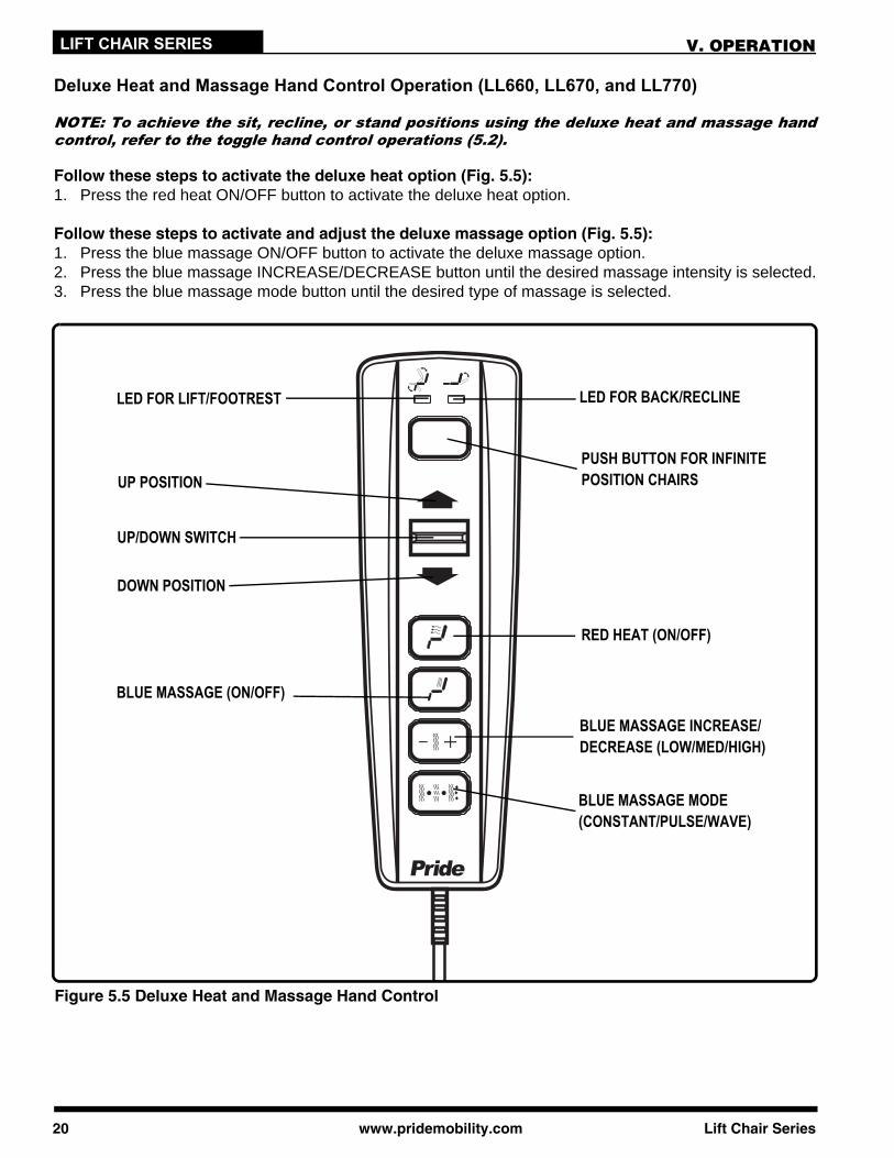
Deluxe Heat and Massage Hand Control Operation (LL660, LL670, and LL770)
NOTE: To achieve the sit, recline, or stand positions using the deluxe heat and massage handcontrol, refer to the toggle hand control operations (5.2).
Follow these steps to activate the deluxe heat option (Fig. 5.5):1. Press the red heat ON/OFF button to activate the deluxe heat option.
Follow these steps to activate and adjust the deluxe massage option (Fig. 5.5):1. Press the blue massage ON/OFF button to activate the deluxe massage option.2. Press the blue massage INCREASE/DECREASE button until the desired massage intensity is selected.3. Press the blue massage mode button until the desired type of massage is selected.
LED FOR BACK/RECLINE
PUSH BUTTON FOR INFINITE POSITION CHAIRS
RED HEAT (ON/OFF)
BLUE MASSAGE INCREASE/DECREASE (LOW/MED/HIGH)
BLUE MASSAGE MODE (CONSTANT/PULSE/WAVE)
LED FOR LIFT/FOOTREST
UP POSITION
UP/DOWN SWITCH
DOWN POSITION
BLUE MASSAGE (ON/OFF)
Figure 5.5 Deluxe Heat and Massage Hand Control
Lift Chair Series www.pridemobility.com 21
LIFT CHAIR SERIES
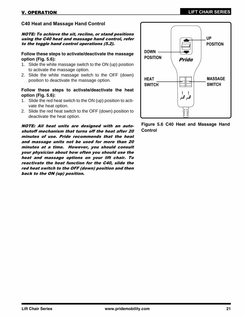
MASSAGE SWITCH
HEAT SWITCH
UP POSITION
DOWN POSITION
V. OPERATION
C40 Heat and Massage Hand Control
NOTE: To achieve the sit, recline, or stand positionsusing the C40 heat and massage hand control, referto the toggle hand control operations (5.2).
Follow these steps to activate/deactivate the massageoption (Fig. 5.6):1. Slide the white massage switch to the ON (up) position
to activate the massage option.2. Slide the white massage switch to the OFF (down)
position to deactivate the massage option.
Follow these steps to activate/deactivate the heatoption (Fig. 5.6):1. Slide the red heat switch to the ON (up) position to acti-
vate the heat option.2. Slide the red heat switch to the OFF (down) position to
deactivate the heat option.
NOTE: All heat units are designed with an auto-shutoff mechanism that turns off the heat after 20minutes of use. Pride recommends that the heatand massage units not be used for more than 20minutes at a time. However, you should consultyour physician about how often you should use theheat and massage options on your lift chair. Toreactivate the heat function for the C40, slide thered heat switch to the OFF (down) position and thenback to the ON (up) position.
Figure 5.6 C40 Heat and Massage HandControl
LIFT CHAIR SERIES VI. TROUBLESHOOTING
Your Pride Lift Chair is a state-of-the-art product designed to enhance your mobility. Your lift chairshould bring you years of trouble-free service, however, it may require occasional troubleshoot-ing. The following troubleshooting tips and FAQs should summarize what you need to know aboutyour lift chair. If at any time you do not feel comfortable performing the troubleshooting stepslisted in this manual, contact your authorized Pride Provider for service. Please have the modelnumber, serial number, and nature of the problem when calling.
22 www.pridemobility.com Lift Chair Series
RED PLUGS
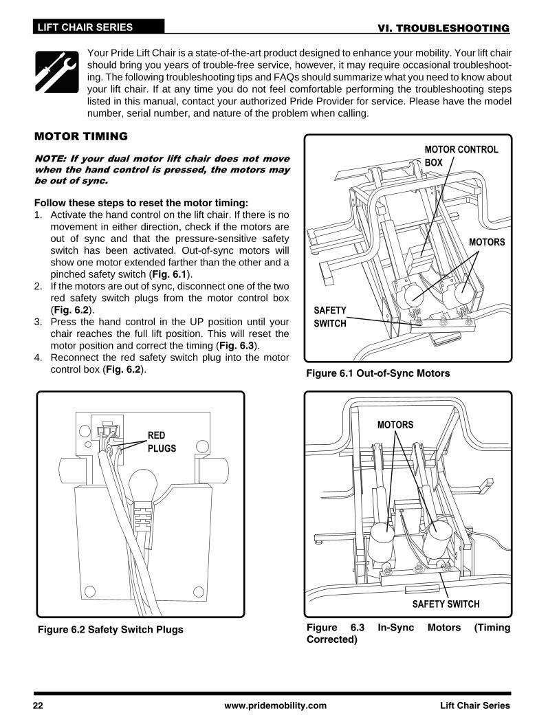
MOTORS
MOTOR CONTROL BOX
SAFETY SWITCH
MOTORS
MOTOR TIMING
NOTE: If your dual motor lift chair does not movewhen the hand control is pressed, the motors maybe out of sync.
Follow these steps to reset the motor timing:1. Activate the hand control on the lift chair. If there is no
movement in either direction, check if the motors areout of sync and that the pressure-sensitive safetyswitch has been activated. Out-of-sync motors willshow one motor extended farther than the other and apinched safety switch (Fig. 6.1).
2. If the motors are out of sync, disconnect one of the twored safety switch plugs from the motor control box(Fig. 6.2).
3. Press the hand control in the UP position until yourchair reaches the full lift position. This will reset themotor position and correct the timing (Fig. 6.3).
4. Reconnect the red safety switch plug into the motorcontrol box (Fig. 6.2).
SAFETY SWITCH
Figure 6.1 Out-of-Sync Motors
Figure 6.2 Safety Switch Plugs Figure 6.3 In-Sync Motors (TimingCorrected)
LIFT CHAIR SERIESVI. TROUBLESHOOTING
FREQUENTLY ASKED QUESTIONS
What if my lift chair does not operate at all?Ensure the external transformer is plugged into a properly wired electrical outlet.Check the circuit breaker box connected to the electrical outlet to ensure the outlet is receiving power.Ensure the low voltage connection cable is plugged into the external transformer.Ensure that all cables are connected properly.Refer to the applicable electrical diagram in the “Appendix” section for proper electrical connections.
What if my lift chair operates in one direction only?Check the up and down buttons or toggle switch on the hand control to make sure they do not stick. Ifthe buttons or switch are sticking in either position, the hand control may need to be replaced.Contact your authorized Pride Provider for further assistance.
What if my lift chair stops during a lifting cycle?Your lift chair is equipped with an internal thermal shutoff switch located inside the external transformerthat prevents the motor control box from overheating. If the thermal shutoff activates, allow the lift chairto remain in a stationary position for 10 minutes to allow the motor to cool, then resume normal operation.If you notice the motors overheating frequently, contact your authorized Pride Provider.There may have been a power failure and/or there are no batteries in the external transformer or thebatteries have no charge. Always make sure there are fresh 9V batteries in the external transformer ifequipped with battery backup.Check the circuit breaker box connected to the electrical outlet to ensure the outlet is receiving power.
What if the heat and massage options on my lift chair do not function?Ensure the junction box is connected properly to the external transformer and that there is power to thetransformer. A green LED will light on the transformer to indicate power.Ensure the heat and massage units are connected properly at the rear of the lift chair. Refer to “AppendixF,” “Appendix G,” or “Appendix H” for proper electrical connections.Ensure the hand control is connected properly to the lift chair. If connected properly, any LEDs on the handcontrol will be lit. Refer to the applicable electrical diagram in the “Appendix” section for proper electricalconnections.If any of the LEDs do not light, contact your authorized Pride Provider for further assistance.
What if my lift chair is rocking from corner to corner after I position the chair?The floor may be uneven or the carpet may be affecting chair position. Adjust the leg levelers in the areawhere the chair is rocking. See III. “Your Lift Chair” for instructions on leveling your chair.
Where can I place the external transformer box?On the floor away from heat sources in an open, well-ventilated area where it will not be an obstruction.On the wall away from heat sources utilizing the optional external transformer wall mount. Refer to“Appendix I” or “Appendix J.”
Where do I find the serial number on my lift chair?You can find the serial number in two locations—one is near the rear of the motor on the steel lift mechanism,the second is attached to the frame below the scissor mechanisms. The model number for your lift chair isprinted below the serial number bar code.
Who do I call for service?Contact your authorized Pride Provider for service.
Lift Chair Series www.pridemobility.com 23
24 www.pridemobility.com Lift Chair Series
LIFT CHAIR SERIES VII. CARE AND MAINTENANCE
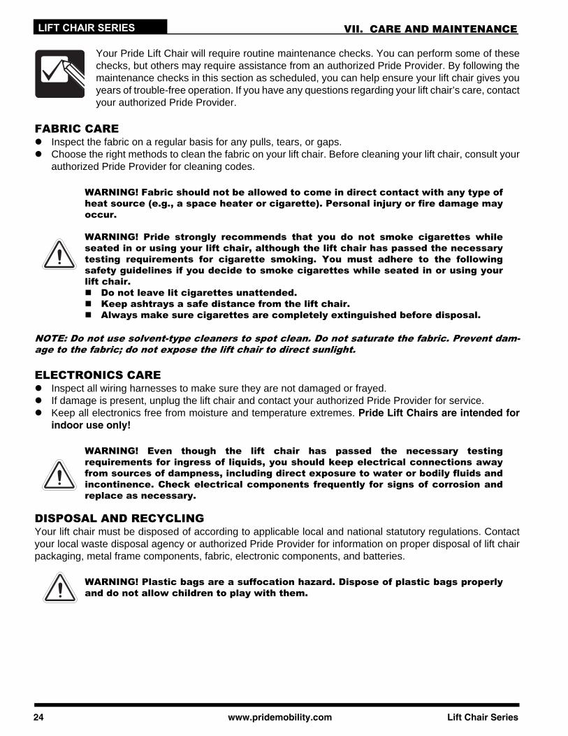
Your Pride Lift Chair will require routine maintenance checks. You can perform some of thesechecks, but others may require assistance from an authorized Pride Provider. By following themaintenance checks in this section as scheduled, you can help ensure your lift chair gives youyears of trouble-free operation. If you have any questions regarding your lift chair’s care, contactyour authorized Pride Provider.
FABRIC CAREInspect the fabric on a regular basis for any pulls, tears, or gaps.Choose the right methods to clean the fabric on your lift chair. Before cleaning your lift chair, consult yourauthorized Pride Provider for cleaning codes.
WARNING! Fabric should not be allowed to come in direct contact with any type ofheat source (e.g., a space heater or cigarette). Personal injury or fire damage mayoccur.
WARNING! Pride strongly recommends that you do not smoke cigarettes whileseated in or using your lift chair, although the lift chair has passed the necessarytesting requirements for cigarette smoking. You must adhere to the followingsafety guidelines if you decide to smoke cigarettes while seated in or using yourlift chair. Do not leave lit cigarettes unattended. Keep ashtrays a safe distance from the lift chair. Always make sure cigarettes are completely extinguished before disposal.
NOTE: Do not use solvent-type cleaners to spot clean. Do not saturate the fabric. Prevent dam-age to the fabric; do not expose the lift chair to direct sunlight.
ELECTRONICS CAREInspect all wiring harnesses to make sure they are not damaged or frayed.If damage is present, unplug the lift chair and contact your authorized Pride Provider for service.Keep all electronics free from moisture and temperature extremes. Pride Lift Chairs are intended forindoor use only!
WARNING! Even though the lift chair has passed the necessary testingrequirements for ingress of liquids, you should keep electrical connections awayfrom sources of dampness, including direct exposure to water or bodily fluids andincontinence. Check electrical components frequently for signs of corrosion andreplace as necessary.
DISPOSAL AND RECYCLINGYour lift chair must be disposed of according to applicable local and national statutory regulations. Contactyour local waste disposal agency or authorized Pride Provider for information on proper disposal of lift chairpackaging, metal frame components, fabric, electronic components, and batteries.
WARNING! Plastic bags are a suffocation hazard. Dispose of plastic bags properlyand do not allow children to play with them.

LIFT CHAIR SERIESVIII. WARRANTY
LIFETIME WARRANTYPride offers a lifetime warranty on the steel lift mechanism. Pride warrants that the steel liftmechanism on your Pride Lift Chair will be free from defects under normal use and service foras long as the chair is in use by the original owner. This lifetime warranty covers the steel liftmechanism against metal fatigue, defective welds, and bushings.
NOTE: Pride reserves the right to replace only the part of the steel lift mechanism that may bedefective.
SEVEN-YEAR PRO-RATED WARRANTY (ELEGANCE and SPECIALTY COLLECTIONS)For the first four (4) years from the date of purchase, Pride will repair or replace at our option to the originalpurchaser any of the following parts found upon examination by an authorized representative of Pride to bedefective in material and/or workmanship: Wood Frame Motor Hand Control Scissor Mechanisms Heat Pad Massage Unit
For three (3) additional years, a pro-rated warranty will be made available for the following parts:Motor Heat Pad Hand Control Massage Unit
Pride will warrant these components with the following pro-rated schedule:Fifth year: 25% off suggested retail priceSixth year: 15% off suggested retail priceSeventh year: 5% off suggested retail price
SEVEN-YEAR PRO-RATED WARRANTY (HERITAGE COLLECTION)For the first three (3) years from the date of purchase, Pride will repair or replace at our option to the originalpurchaser any of the following parts found upon examination by an authorized representative of Pride to bedefective in material and/or workmanship:
Wood Frame Motor Hand Control Scissor Mechanisms Heat Pad Massage Unit
For four (4) additional years, a pro-rated warranty will be made available for the following parts:Motor Heat Pad Hand Control Massage Unit
Pride will warrant these components with the following pro-rated schedule:Fourth year: 35% off suggested retail priceFifth year: 25% off suggested retail priceSixth year: 15% off suggested retail priceSeventh year: 5% off suggested retail price
FOUR-YEAR LIMITED WARRANTY (LL805KD)For four (4) years from the date of purchase, Pride will repair or replace at our option to the original purchaserany of the following parts found upon examination by an authorized representative of Pride to be defective inmaterial and/or workmanship:
Wood Frame Motor Hand Control Scissor Mechanisms Heat Pad Massage Unit
TWO-YEAR LIMITED WARRANTY (CLASSIC COLLECTION and C40)For two (2) years from the date of purchase, Pride will repair or replace at our option to the original purchaserany of the following parts found upon examination by an authorized representative of Pride to be defective inmaterial and/or workmanship:
Wood Frame Motor Hand Control Scissor MechanismsHeat Pad Massage Unit Metal Frame (LC105 only)
Lift Chair Series www.pridemobility.com 25

LIFT CHAIR SERIES VIII. WARRANTY
ONE-YEAR LIMITED WARRANTY (LC105)For one (1) year from the date of purchase, Pride will repair or replace at our option to the original purchaserany of the following parts found upon examination by an authorized representative of Pride to be defective inmaterial and/or workmanship: Motor Hand Control Scissor Mechanisms
RECONDITIONED UNITS WARRANTYAll reconditioned units are covered by a six-month warranty from Pride effective from the date of purchase.
WARRANTY EXCLUSIONSThis warranty does not extend to fabric and excludes steel frame chairs.Pride is not responsible or obligated to pay for labor, service calls, shipping, and/or any other chargesincurred for repair of the product. All transportation costs and shipping damage incurred while submittingparts for repair or replacement are the responsibility of the purchaser. Please contact your authorized PrideProvider for information on the current cost associated with a service visit. Circumstances beyond the control of Pride Labor, service calls, shipping, and other charges incurred for repair of the product, unless specifically
authorized, IN ADVANCE, by Pride Mobility Products Corporation Repairs and/or modifications made to any part without specific consent from Pride
Exclusions also include components with damage caused by: Contamination Abuse, misuse, accident, or negligence Battery fluid spillage or leakage Commercial use, or use other than normal Improper operation, maintenance, or storage
IMPLIED WARRANTIESImplied warranties, including those of merchantability and fitness for a particular purpose, are limitedto one (1) year from the date of purchase and to the extent permitted by law. Any and all other impliedwarranties are excluded. This is the exclusive remedy. Liabilities for consequential damages under any andall warranties are excluded.
Some states do not allow limitations on how long an implied warranty lasts or do not allow the exclusion orlimitation of incidental or consequential damages. The above limitation or exclusion may not apply to you.
This warranty gives you specific rights, and you may also have other rights which vary from state to state.
Please fill out and return the product registration card to Pride. This will aid Pride in providing the best possibletechnical and customer service.
26 www.pridemobility.com Lift Chair Series
Lift Chair Series www.pridemobility.com 27
LIFT CHAIR SERIES
LL805KD
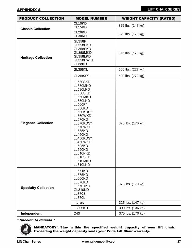
MANDATORY! Stay within the specified weight capacity of your lift chair.Exceeding the weight capacity voids your Pride Lift Chair warranty.
PRODUCT COLLECTION MODEL NUMBER WEIGHT CAPACITY (RATED)
Classic CollectionCL10KDCL15KD 325 lbs. (147 kg)
CL20KDCL30KD 375 lbs. (170 kg)
Heritage Collection
GL358PGL358PKDGL358SKDGL358MKDGL358LKDGL358PWKDGL58KD
375 lbs. (170 kg)
GL358XL
GL358XXL
500 lbs. (227 kg)
600 lbs. (272 kg)
Elegance Collection
LL530SKDLL530MKDLL530LKDLL550SKDLL550MKDLL550LKDLL560P*LL560KDLL560KDS*LL560WKDLL570KDLL570KDS*LL570WKDLL585KDLL450KDLL450KDS*LL450WKDLL595KDLL590KDLL510PKDLL510SKDLL510MKDLL510LKD
300 lbs. (136 kg)
375 lbs. (170 kg)
Specialty Collection375 lbs. (170 kg)
APPENDIX A
* Specific to Canada *
325 lbs. (147 kg)
LL571KDLL575KDLL660KDLL670KDLL570TKDGL310KDLL770SLL770L
LC105
C40 375 lbs. (170 kg)Independent
28 www.pridemobility.com Lift Chair Series
LIFT CHAIR SERIES APPENDIX B
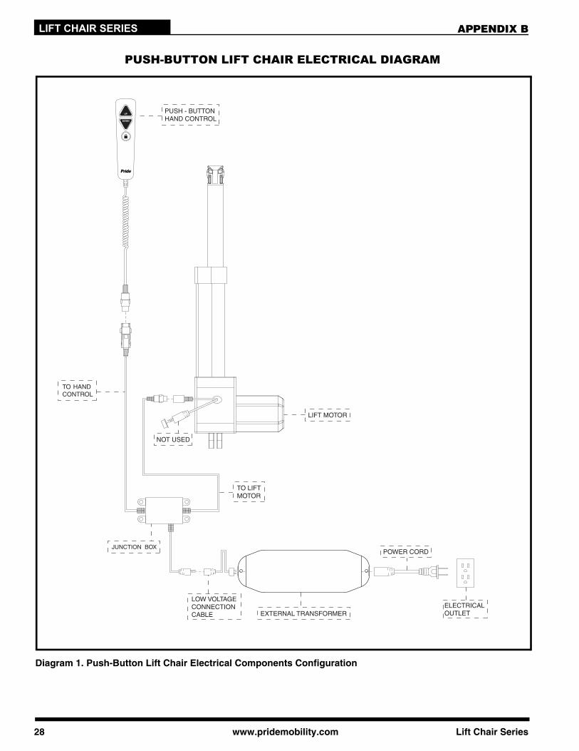
PUSH-BUTTON LIFT CHAIR ELECTRICAL DIAGRAM
Diagram 1. Push-Button Lift Chair Electrical Components Configuration
NOT USED
TO LIFT MOTOR
Lift Chair Series www.pridemobility.com 29
LIFT CHAIR SERIESAPPENDIX C
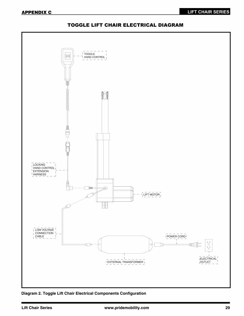
TOGGLE LIFT CHAIR ELECTRICAL DIAGRAM
Diagram 2. Toggle Lift Chair Electrical Components Configuration
30 www.pridemobility.com Lift Chair Series
LIFT CHAIR SERIES
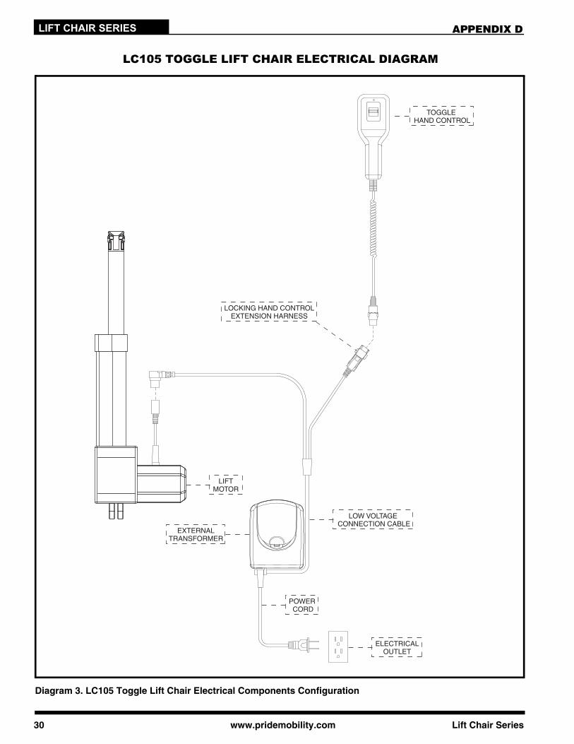
TOGGLE HAND CONTROL
ELECTRICALOUTLET
LOW VOLTAGE CONNECTION CABLE
LOCKING HAND CONTROLEXTENSION HARNESS
EXTERNALTRANSFORMER
POWER CORD
LIFTMOTOR
APPENDIX D
LC105 TOGGLE LIFT CHAIR ELECTRICAL DIAGRAM
Diagram 3. LC105 Toggle Lift Chair Electrical Components Configuration
Lift Chair Series www.pridemobility.com 31
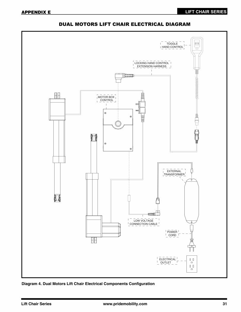
LIFT CHAIR SERIESAPPENDIX E
Diagram 4. Dual Motors Lift Chair Electrical Components Configuration
DUAL MOTORS LIFT CHAIR ELECTRICAL DIAGRAM
32 www.pridemobility.com Lift Chair Series
LIFT CHAIR SERIES
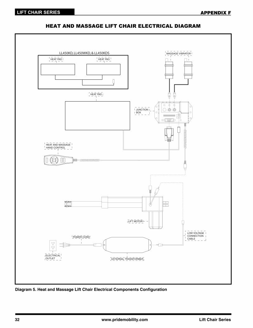
HEAT AND MASSAGE LIFT CHAIR ELECTRICAL DIAGRAM
Diagram 5. Heat and Massage Lift Chair Electrical Components Configuration
LL450KD, LL450WKD, & LL450KDS
APPENDIX F
Lift Chair Series www.pridemobility.com 33
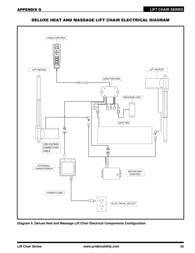
LIFT CHAIR SERIESAPPENDIX G
DELUXE HEAT AND MASSAGE LIFT CHAIR ELECTRICAL DIAGRAM
Diagram 6. Deluxe Heat and Massage Lift Chair Electrical Components Configuration
HAND CONTROL
LIFT MOTOR
EXTERNALTRANSFORMER
HEAT PAD
LOW VOLTAGECONNECTIONCABLE
ELECTRICAL OUTLET
POWER CORD
MOTOR BOXCONTROL
MASSAGE UNIT
LIFT MOTOR
JUNCTION BOX
34 www.pridemobility.com Lift Chair Series
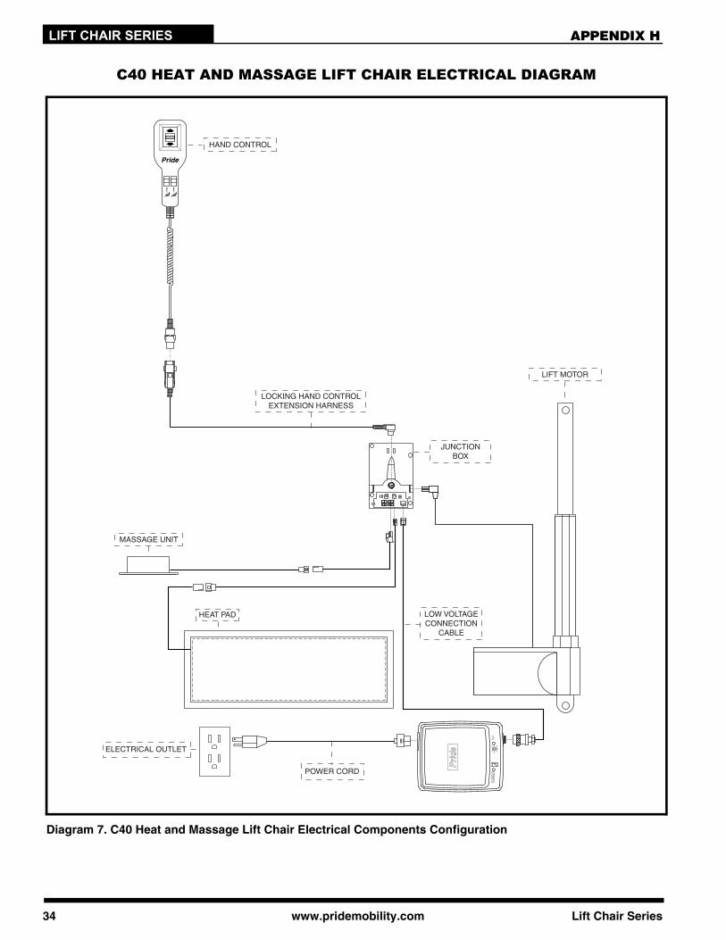
LIFT CHAIR SERIES APPENDIX H
C40 HEAT AND MASSAGE LIFT CHAIR ELECTRICAL DIAGRAM
Diagram 7. C40 Heat and Massage Lift Chair Electrical Components Configuration
HAND CONTROL
HEAT PAD LOW VOLTAGECONNECTION
CABLE
ELECTRICAL OUTLET
POWER CORD
JUNCTIONBOX
LOCKING HAND CONTROLEXTENSION HARNESS
MASSAGE UNIT
LIFT MOTOR
Lift Chair Series www.pridemobility.com 35
LIFT CHAIR SERIES
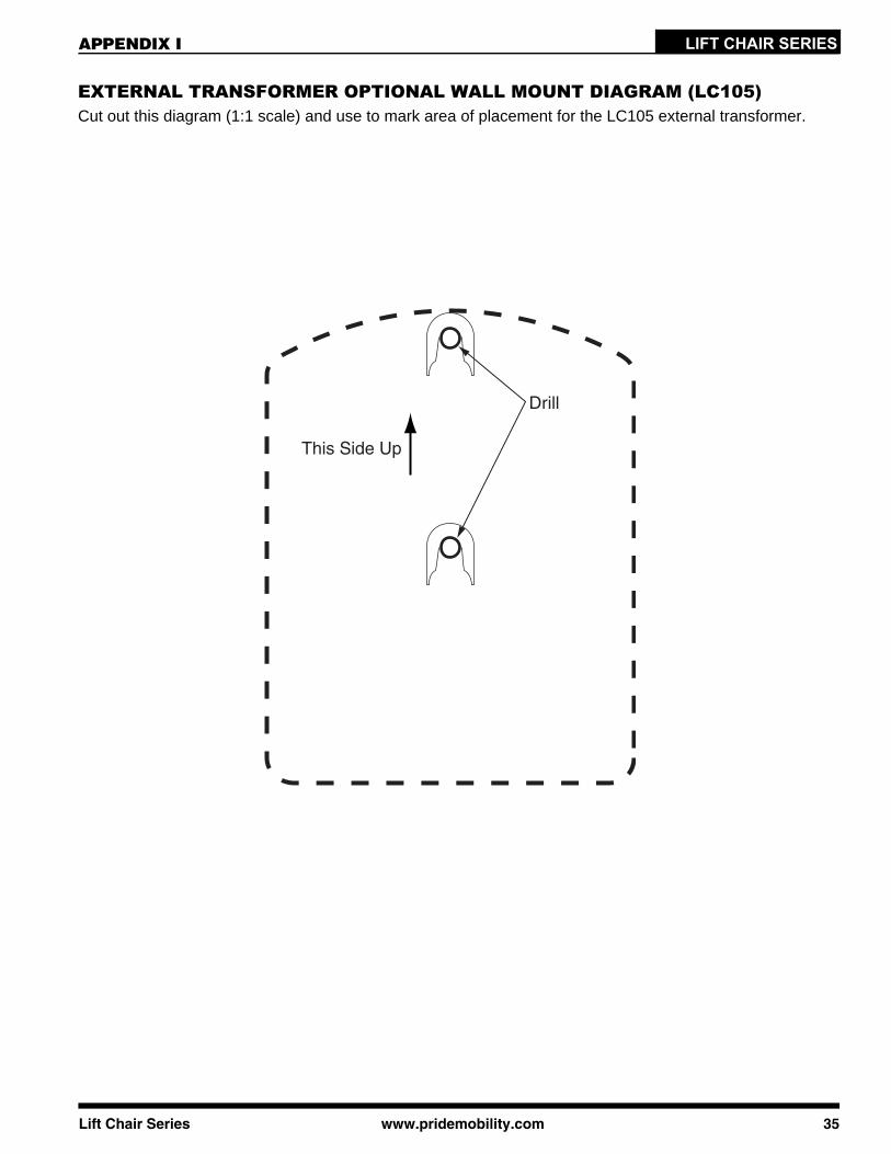
Drill
This Side Up
APPENDIX I
EXTERNAL TRANSFORMER OPTIONAL WALL MOUNT DIAGRAM (LC105)Cut out this diagram (1:1 scale) and use to mark area of placement for the LC105 external transformer.

36 www.pridemobility.com Lift Chair Series
LIFT CHAIR SERIES APPENDIX I
(This page intentionally left blank.)
Lift Chair Series www.pridemobility.com 37
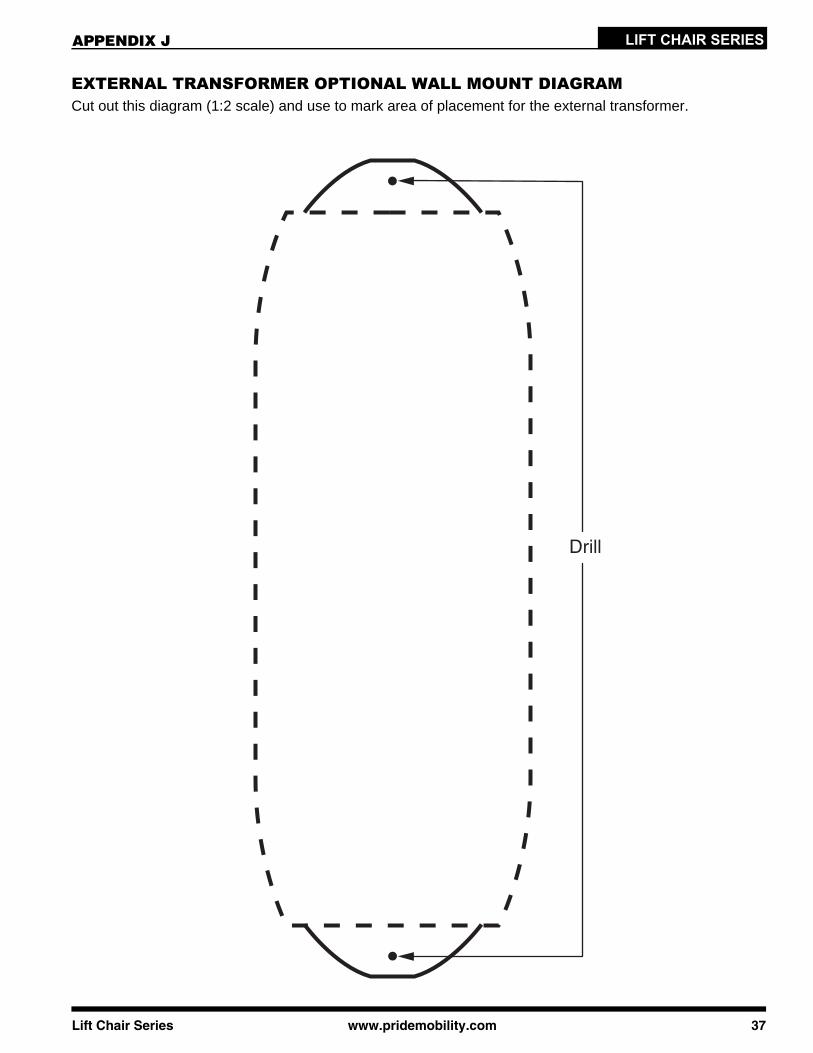
LIFT CHAIR SERIES
EXTERNAL TRANSFORMER OPTIONAL WALL MOUNT DIAGRAMCut out this diagram (1:2 scale) and use to mark area of placement for the external transformer.
Drill
APPENDIX J

38 www.pridemobility.com Lift Chair Series
LIFT CHAIR SERIES
(This page intentionally left blank.)
APPENDIX J

The symbols below are used throughout this owner's manual and on the product to identify warnings andimportant information. It is very important for you to read them and understand them completely.
WARNING! Indicates a potentially hazardous condition/situation. Failure to followdesignated procedures can cause either personal injury, component damage, ormalfunction. On the product, this icon is represented as a black symbol on a yellowtriangle with a black border.
MANDATORY! These actions should be performed as specified. Failure to performmandatory actions can cause personal injury and/or equipment damage. On theproduct, this icon is represented as a white symbol on a blue dot with a whiteborder.
PROHIBITED! These actions are prohibited. These actions should not be performedat any time or in any circumstances. Performing a prohibited action can causepersonal injury and/or equipment damage. On the product, this icon is representedas a black symbol with a red circle and red slash.
SAFETY GUIDELINESLIFT CHAIR SERIES
NOTE: This owner’s manual is compiled from the latest specifications and product informationavailable at the time of publication. We reserve the right to make changes as they become nec-essary. Any changes to our products may cause slight variations between the illustrations andexplanations in this manual and the product you have purchased. The latest/current version ofthis manual is available on our website.
Copyright © 2010Pride Mobility Products Corp.INFMANU3446/Rev I/January 2010
Please fill out the following information for quick reference:
Pride Provider:
Address:
Phone Number:
Purchase Date: Serial Number:
088 609 661

®
®
LIFT CHAIRSERIES
1-800-800-8586 (US) 1-888-570-1113 (Canada)
182 Susquehanna Avenue Exeter, PA 18643-2694
www.pridemobility.com