plt series lift - autoquip
TRANSCRIPT

S
P.O. Bo
Item # 83
INSTALLATION, OPERATION
AND SERVICE MANUAL
BASCULE BRIDGEINGLE LEAF & DOUBLE LEAF
x 1058 • 1058 West Industrial Avenue • Guthrie, OK 73044-1058 • 405-282-5200
• FAX: 405-282-8105 • www.autoquip.com
0BB Version 1.0
01/30/03

Identification & Ins Dangers, Warnings Safety Features Label Identification Specifications Blocking Instructio Installation Instruct Operating Instructi Routine Maintenan General Maintenan Replacement Parts Troubleshooting A
Please read and equipment. Failurinjury. If question811-9876 or 405-2
P
A local Autoquip rthis equipment usiCorporation at 1-88
TABLE OF CONTENTS
pection 3
, and Cautions 4
7
8
12
ns 13
ions 14
ons 26
ce 28
ce 30
List 40
nalysis 41
IMPORTANT
understand this manual prior to installation or operation of this e to do so could lead to property damage and/or serious personal s arise, call a local representative or Autoquip Corporation at 1-888-82-5200.
LANNED MAINTENANCE PROGRAM
epresentative provides a Planned Maintenance Program (PMP) for ng factory-trained personnel. Call a local representative or Autoquip 8-811-9876 or 405-282-5200 for more information.
2

IDENTIFICATION When ordering parts or reTO THE MODEL AND SERto the lift platform. Replace
INSPECTION
Immediately upon receipt that the lift has not been ddelivery receipt. In additioinspected for concealed dathe delivery receipt should
The following is a checklist
1. Examine entire unit for unit and controls.
2. Thoroughly examine a
during transit. 3. Check to make sure t
missing, contact the Au
INSPECTION
questing information or service on this lift, PLEASE REFER IAL NUMBER. This information is on a nameplate attached ment parts are available from a local Autoquip distributor.
of the lift, a visual inspection should be made to determine amaged in transit. Any damage found must be noted on the n to this preliminary inspection, the lift should be carefully mage. Any concealed damage found that was not noted on be reported in writing to the delivering carrier within 48 hours.
that will aid in the inspection of the lift.
any signs of mishandling. Pay special attention to the power
ll connections, making sure they have not vibrated loose
at there are no missing parts. If any parts appear to be toquip Customer Assurance Department immediately.
3

DANGERS, WARNINGS & CAUTIONS
SAFETY ALERTS (Required Reading!) The following SAFETY ALERTS are intended to create awareness of owners, operators, and maintenance personnel of the potential safety hazards and the steps that must be taken to avoid accidents. These same alerts are inserted throughout this manual to identify specific hazards that may endanger uninformed personnel. Identification of every conceivable hazardous situation is impossible. Therefore, all personnel have the responsibility to diligently exercise safe practices whenever exposed to this equipment. ____________________________________________________________
DANGER!
Identifies a hazardous situation that presents the imminent probability of death or of severe personal injury!! _____________________________________________________________
WARNING! Identifies a hazardous situation that has the potential of causing death or serious personal injury.
CAUTION!
Identifies a hazardous situation that could lead to the possibility of personal injury of death, and/or may result in equipment damage. _____________________________________________________________
4

Read and understand this manual and all labels prior to operating or servicing the bridge. All labels are provided in accordance with ANSI Z535.4. DANGER! To avoid personal injury, stand clear of the bridge and handrails while it is in motion. DANGER! HIGH VOLTAGE!! Disconnect and/or lock out the electrical supply to the power unit prior to any maintenance being performed. DANGER! NEVER go under the bridge or perform maintenance until the load is removed and the bridge is securely blocked. See “Blocking Instructions” section in this manual. WARNING! All warning and information decals should be in place as outlined in the “Label Identification” section. If decals are missing or damaged, they should be replaced with new ones. Contact an Autoquip representative for replacements.
DANGERS, WARNINGS & CAUTIONS
5

WARNING! Under circumstances should the flow control be modified or removed from the pump or Deltatrol to obtain faster lowering speed. A loaded lift can reach dangerous and destructive speed and/or unnecessary closing of the velocity fuses. WARNING!
NO RIDERS when the bridge is in motion.
CAUTION!
Become familiar with this manual before operating this equipment.
CAUTION!
Use only approved oils. See “Oil Requirements” in the Maintenance Section.
CAUTION!
Precaution should be taken to prevent the introduction of contaminates such as dirt or other foreign material into the system through open fittings, pipes, or disassembled components. Contamination will ruin the hydraulic system.
DANGERS, WARNINGS & CAUTIONS
CAUTION!
The bridge must be fully lowered before moving a load onto it. Serious damage to the bridge and its components can result.
6

SAFETY FEATURES
HYDRAULIC VELOCITY FUSES Each hydraulic cylinder has a hydraulic velocity fuse (HVF) installed in the cylinder port. These HVFs are installed in the predetermined hydraulic oil flow velocity as the oil returns to the reservoir. They do not affect incoming oil. Should a catastrophic rupture or breach occur in the hydraulic system and oil flows through the breach that exceeds the HVF rating, the HVF will trigger and lock up. This lock up will occur with one to two inches of downward movement of the platform carriage. NOTE: Air in the system will also cause a lock up. Air acts like a spring when compressed. To remove air from the system, see “Air Bleeding Procedures” in the General Maintenance section. NOTE: Small fitting leaks will trigger the HVFs. In an air-free system, the breach must be large enough to cause an uncontrolled or destructive lowering speed. Should a triggering and loc up occur, it can only be released by applying upward hydraulic flow in a functional system. SAFETY RELEASE BYPASS VALVE (SRBV) The SRBV is a part of the hydraulic system. Should the system pressure exceed the predetermined pressure setting, the SRBV will bypass the pump output back to the oil reservoir. The SRBV is factory set to the proper pressure, which will prevent damage to the mechanical, hydraulic, and electrical systems due to overloading, obstruction, or other circumstances. SAFETY LEGS / SAFETY WINGS The safety legs are automatic devices which serve two critical safety functions:
1. If the bridge is left open over a long period of time (possibly over the weekend) a slow downward drift may occur due to the normal bleeding of hydraulic pressure across the valve seats in the check valve and dump valve. In the extended position, the safety legs will make contact with the adjacent curb angles, prevent the bridge from drifting any further, and maintain the bridges vertical position.
2. If the bridge were to experience a sudden and unexpected loss of hydraulic pressure while being stored in the vertical position, the safety legs would support the bridge until repairs could be made.
7

7 2 4 6 51 3 1 52
LABEL IDENTIFICATION
Figure 1 Label Placement
Bascule Bridge Item No. Qty Description Part No.
1 3 Caution: Do not go under Lift Platform 36400679 2 3 Caution: Familiarize Yourself With Operators Manual 36401487 3 2 Capacity 36401602 4 2 Caution: Stay Clear of Lift Mechanism 36403046 5 3 Warning: No Riders 36403707 6 2 Warning: Stay Clear While Platform is Tilting 36403830 7 1 Autoquip Serial Number Nameplate 36401511
8

LABEL IDENTIFICATION
Note: Labels shown here are not actual size.
Figure 2 Label 36400679
Figure 3 Label 36401487
Figure 4 Label 36401602
9

LABEL IDENTIFICATION
Figure 5 Label 36403046
Figure 6 Label 36403707
Figure 7 Label 36403830
10

LABEL IDENTIFICATION
Figure 8 Label 36401511
11

Model Plat.
Width (feet)
Face to Face of Cutouts (inches)
BB-1 BB-2 BB-3 BB-4
16
BB-5 BB-6 BB-7 BB-8
17
BB-9 BB-10 BB-11 BB-12
18
BB-13 BB-14 BB-15 BB-16
19
BB-17 BB-18 BB-19 BB-20
6
20
BB-21 BB-22 BB-23 BB-24
16
BB-25 BB-26 BB-27 BB-28
17
BB-29 BB-30 BB-31 BB-32
18
BB-33 BB-34 BB-35 BB-36
19
BB-37 BB-38 BB-39 BB-40
8
20
NOTES: 1. Units with other specific2. Single leaf bascule brid3. For the double leaf brid4. Double leaf bascule br
controls. Each leaf ope5. Shipping weight of dou
bridge and adding appr
SPECIFICATIONS
Load Cap. (lbs)Axle Load Cap. (lbs)
Act. Plat Length
Plat. Depth (in.)
Speed(sec)
# of Rams
Hinge ChannelLength
Total ReactionIn KIPS
Ship Wt.
10,000 8,000 8 1/4 60 1 19 4100 15,000 12,000 8 1/4 60 1 20 4500 20,000 16,000 10 5/16 90 2 23 5200 30,000 24,000
15’ 10 ¼”
10 5/16 90 2 24 5500 10,000 8,000 8 1/4 60 1 21 4300 15,000 12,000 8 1/4 60 1 22 4700 20,000 16,000 10 5/16 25 5500 30,000 24,000
16’ 10 ¼”
10 5/16 26 5800 10,000 8,000 8 1/4 23 4800 15,000 12,000 8 1/4 24 5100 20,000 16,000 10 5/16 27 5800 30,000 24,000
17’ 10 ¼”
10 5/16 28 6100 10,000 8,000 8 1/4 25 5000 15,000 12,000 8 1/4 26 5300 20,000 16,000 10 5/16 29 6000 30,000 24,000
18’ 10 ¼”
10 5/16 30 6400 10,000 8,000 8 1/4 27 5200 15,000 12,000 8 1/4 28 5500 20,000 16,000 10 5/16 31 6200 30,000 24,000
19’ 10 ¼”
10 5/16
6’ 10”
32 6700 10,000 8,000 8 1/4 24 5400 15,000 12,000 8 1/4 25 5800 20,000 16,000 10 5/16 28 6500 30,000 24,000
15’ 10 ¼”
10 5/16 31 7100 10,000 8,000 8 1/4 26 5700 15,000 12,000 8 1/4 27 6100 20,000 16,000 10 5/16 30 6800 30,000 24,000
16’ 10 ¼”
10 5/16 33 7400 10,000 8,000 8 1/4 28 6000 15,000 12,000 8 1/4 29 6400 20,000 16,000 10 5/16 32 7200 30,000 24,000
17’ 10 ¼”
10 5/16
90
2
35 7800 10,000 8,000 8 1/4 32 6400 15,000 12,000 8 1/4 34 6900 20,000 16,000 10 5/16 38 7700 30,000 24,000
18’ 10 ¼”
10 5/16 41 8300 10,000 8,000 8 1/4 34 6700 15,000 12,000 8 1/4 36 7200 20,000 16,000 10 5/16 40 8000 30,000 24,000
19’ 10 ¼”
10 5/16
130 3
8’ 10”
43 8600
ations are available upon request. ges up to 30” long with capacities to 100,000 lbs are available. ge, use two single leaf bridges. idges have two power units, two automatic safety latches, and two sets of rates independently. ble leaf bascule bridges is determined by doubling the weight of single leaf oximately 500 lbs for folding support legs.
12

S
1. Low 2. Pla
3. Dri
pre
4. To pos
BLOCKING INSTRUCTION
DANGER!
NEVER go under the bridge or perform maintenance until the load is removed and the bridge is securely blocked.
er the empty bridge platform into the horizontal position.
ce temporary supports under all corners of the bridge frame.
ve shims and/or blocks between the bridge frame and the supports to relieve ssure from the lifting cylinders.
remove temporary supports, hydraulically raise the bridge to the vertical ition.
13

NEVsec
BRIDGE (1. Set th
suppoNOTEby the
2. Tack-w
raise o5/16” irequire
3. Greas LIFTING C4. Bolt th
thick sbase c
5. Line u
exactlychann
POWER U6. The p
bridgeelemein accschem
7. Check
changpumpe
8. Fill the
section
INSTALLATION INSTRUCTIONS
DANGER!
ER go under the bridge until the load is removed and the bridge is urely blocked. See “Blocking Instructions” section in this manual.
See Figures 9 through 13) e bridge in the correct horizontal position (on “horses” or temporary welded rts). Line up accurately with the dock and hinge channel. : Hinge channel and clevis channel MUST be set plumb, square, and parallel pit contractor.
eld the male hinge clevises securely in place. Remove the hinge pins and r lower the bridge enough to expose the clevises for full welds. Weld securely nch fillets all around (shim between the imbedded channel and the clevises, if d).
e the hinge pins and reset the bridge on the hinges.
YLINDERS (See Figure 14) e cylinder base clevis to the tapped clevis block using only two of the ¼” him plates between them. Connect the cylinder to the bridge clevis and the levis.
p the clevises and rams accurately, with the bottom clevis-pin-centerline 15 ¾” out from the hinge channel face. Weld the clevis blocks to the base
el, 5/16” fillets all around.
NIT (See Figures 15 and 16) ower unit can be mounted in any area that is less than 12 feet above the and less than 30 feet away from the bridge, and is protected from the nts. The power unit must be lagged down. The electrical work is to be done ordance with local codes by a qualified electrician. See the electrical atic in the Maintenance section of this manual for proper electrical installation.
the motor rotation for proper direction. Switch the leads if necessary to e the motor direction. NOTE: Precautions must be taken to collect fluid d from the reservoir when checking the motor rotation.
power unit reservoir with fluid as per the instructions in the “Maintenance” .
14

9. Conn
scheScheratedsealasure24” cmou
BRIDGE A10. Care
slowyou
11. If the
ramscorreof thotheaddit
12. If the
out the bverticrech
13. The
push 14. Unle
devicbendexten
INSTALLATION INSTRUCTIONS
CAUTION!
Precaution should be taken to prevent the introduction of contaminates such as dirt or other foreign material into the system through open fittings, pipes, or disassembled components. Contamination will ruin the hydraulic system.
ect the power unit to the lift and safety leg cylinders. Refer to the hydraulic matic in the Maintenance Section of this manual. Pipe that is used must be dule 80 with extra heavy fittings. All hoses, fittings, and pipe is to have a operating pressure of 3000 PSI minimum. Apply the recommended pipe nt to insure a pressure tight fit. Check the routing of the hydraulic lines to be
that the hoses and pipes are clear of all moving parts and remain within the utout area (for pit mounted power units) or an 18” storage area (for remote ly
nted power units). Do not use Teflon tape.
DJUSTMENTS fully raise (to only about half way) and lower the bridge a few times. Then, ly raise it to the full vertical position but not beyond a vertical position, or may destroy the rams.
bridge does not go all the way to the desired vertical position and the ram (or ) are at the end of their strokes, add shims under the base clevis until the ct posture is reached. On multiple ram bridges, all rams must reach the end
eir strokes in unison. Shim carefully so that no ram “bottoms out” ahead of the r rams, or it can be damaged by having to resist the forces of all other rams in ion to its own.
bridge is at its correct vertical position but the cylinders are not all the way (which could let the bridge go beyond vertical), remove the shims from under ase clevis. Test this by carefully inching the bridge after it has reached the al position. If it appears capable of going beyond vertical, remove a shim and
eck it.
base clevis shims control the raised position of the bridge. Adding shims es it away from the cylinders. Removing the shims pulls it toward them.
ss otherwise noted, only the rams must stop the bridge travel. Use of any e to stop the bridge before the rams reach their full stroke can result in ing their rods by the full hydraulic pressure being applied near the maximum ded length.
15

15. C
sthp
16. T
tiss
17. L
tra
18. A
re
19. Are
Clean U
1. Cg
2. T
s
INSTALLATION INSTRUCTIONS
CAUTION!
Never unbolt the clevises or try to change the shims when the bridge is not resting solidly in its fully lowered position.
heck the fluid level in the reservoir and replenish if necessary. See the fluid pecifications in the Maintenance Section of this manual. Cycle the bridge to set e limit switch tripping locations. NOTE: Initial limit switch settings should revent over travel of the safety legs and bridge, or damage may occur.
o remove air from the cylinders, raise the bridge and manually lower it 10 – 15 mes by using the Manual Lowering Valve. Hold the valve open 30 to 40 econds after the cylinders are in the fully collapsed position (the bridge weight hould be resting on the bottomed out cylinders).
ocate the bridge position limit switch and adjust it so that when it strikes and ips against the lifting cylinder, the safety legs just clear the top of the pit curb ngles.
djust the safety leg retract limit switches to trip when the safety legs are fully tracted.
djust the safety leg extend limit switches to trip when the safety legs are fully tracted.
p
lean up any spilled oil and debris from the area. A clean installation makes a ood impression and creates a much safer environment!
ouch-up paint is available by request from Autoquip for repair of damaged paint urfaces.
16

REM
OTE
PO
WER
UN
ITFO
R P
OW
ER U
NIT
MO
UN
TED
REM
OTE
LY, I
NST
ALL
THE
(3)
INSTALLATION INSTRUCTIONS
____" HINGE CHANNELLENGTH
____" CLEVIS CHANNELLENGTH AND DOCK
OPENING
NO
N -
SKID
REM
OTE
PO
WER
UN
IT T
O C
UTO
UT
FOR
LIF
TIN
G R
AMS.
(1) 1
/2" (
SCH
. 80)
BLA
CK
PIPE
& F
ITTI
NG
S FR
OM
REM
OTE
PO
WER
UN
IT T
O C
UTO
UT
FOR
SAF
ETY
LEG
S.
____
_" (_
_' -
__")
DO
CK
FAC
E TO
DO
CK
FAC
E
HYD
RAU
LIC
LIN
ES &
(1) C
ON
TRO
L C
ON
DU
IT.
(2) 3
/8" (
SCH
. 80)
BLA
CK
PIPE
& F
ITTI
NG
S FR
OM
6"H
WH
EEL
CU
RBS
3" x
3" x
1/4
" TH
K. C
UR
B
TYPI
CAL
BO
TH E
ND
SAN
GLE
S BY
PIT
CO
NTR
ACTO
R.
15 1
/4"
FOR
PO
WER
UN
IT M
OU
NTE
D U
ND
ER B
RID
GE
ON
TH
E C
UTO
UT,
INST
ALL
ON
LY
MO
UN
TED
ON
24"
CU
TOU
T
PIT
MO
UN
TED
PO
WER
UN
IT
___"
___"
THE
(2) C
ON
DU
ITS.
(2) 3
/4" C
ON
DU
ITS.
(1) F
OR
CO
NTR
OL
& (1
) FO
R P
OW
ER.
PLAC
EMEN
T W
HEN
HYD
RAU
LIC
PO
WER
UN
IT
22"
2" C
LEAR
ANC
E
26"
12"
18"
CU
TOU
T IF
DES
IRED
.
STEE
L PL
ATE
POW
ER U
NIT
ON
TH
E 24
" MIN
. W
ILL
PER
MIT
INST
ALLA
TIO
N O
FST
AND
ARD
SPA
CIN
G O
F R
AMS
24" C
UTO
UT
Figure 9 Single Leaf Bascule Bridge – Plan View
17

EAC
H E
ND
OF
DO
CK
WIL
L H
AVE
(1) P
USH
-BU
TTO
N S
TATI
ON
.
NO
TES:
INSTALLATION INSTRUCTIONS
(1) 1
/2" E
XTR
A H
EAVY
FOR
CO
MPL
ETE
DET
AILS
ON
PIP
E AN
D
INTO
24"
CU
TBAC
KR
ECES
SES
CO
MPL
ETLY
BRID
GE
IN R
AISE
D P
OSI
TIO
N
HIN
GE
REA
CTI
ON
= _
____
___
LBS.
(TYP
. EAC
H B
RID
GE)
PLU
S D
ESIR
ED S
AFET
Y FA
CTO
R
CO
ND
UIT
SIZ
ES &
LO
CAT
ION
S, S
PEC
IFIC
ATIO
NS
AND
NO
TES,
SEE
DO
UBL
E BA
SCU
LE
BRID
GE
PLAN
VIE
W.
____
__" (
___'
- __
___"
) BR
IDG
E LE
NG
TH
CO
NC
RET
E TO
TAK
E R
EAC
TIO
NS,
PLU
S D
ESIR
ED
WEI
GH
T PL
US
1.3
TIM
ES M
AXIM
UM
LO
AD. R
EIN
FOR
CE
REA
CTI
ON
IN C
ON
CR
ETE
EQU
ALS
TOTA
L BR
IDG
E VE
LOC
ITY
FUSE
S.24
" MIN
.C
UTO
UT
REM
OTE
PO
WER
UN
IT
GAL
VAN
IZED
PIP
ES(2
) 3/8
" EXT
RA
HEA
VY
GAL
VAN
IZED
PIP
E
3/4"
CLE
ARAN
CE
35 1
/2" 8"
LC
16" M
IN.
15 1
/4"
CU
TOU
T D
EPTH
6" H
IGH
WH
EEL
CU
RBS
ON
BO
TH B
RID
GES
, BO
THSI
DES
1" C
LEAR
ANC
E
____
"
AND
DO
CK
HEI
GH
T.
____
_"PL
ATFO
RM
DEP
THSH
IM A
S R
EQ'D
. TO
EQU
ALIZ
E BR
IDG
E
CH
RO
ME
PLAT
ED R
OD
S AN
DLI
FTIN
G C
YLIN
DER
S W
ITH
(TYP
. BO
TH E
ND
S.)
THIS
PO
INT
TO C
ENTE
R L
INE
OF
TRAC
K.C
HEC
K R
AILR
OAD
CLE
ARAN
CES
REQ
'D F
RO
M
SAFE
TY F
ACTO
R. B
Y PI
T C
ON
TRAC
TOR
.
Figure 10 Single Leaf Bascule Bridge – Elevation View
18

INSTALLATION INSTRUCTIONS
3" x
3" x
1/4
" TH
K. x
24"
LG
.
PLAC
EMEN
T W
HEN
(TYP
ICAL
BO
TH E
ND
S)
CU
RB
ANG
LES
BY P
IT C
ON
TRAC
TOR
.
HYD
RAU
LIC
PO
WER
UN
IT
MO
UN
TED
ON
24"
CU
TOU
T.
(2) 3
/8" (
SCH
. 80)
BLA
CK
PIPE
& F
ITTI
NG
S FR
OM
REM
OTE
PO
WER
UN
IT
FOR
PO
WER
UN
IT M
OU
NTE
D R
EMO
TELY
, IN
STAL
L TH
E (3
) H
YDR
AULI
C L
INES
& (1
) CO
NTR
OL
CO
ND
UIT
.
15 1
/4"
24" C
UTO
UT
(1) 1
/2" (
SCH
. 80)
BLA
CK
PIPE
& F
ITTI
NG
S FR
OM
REM
OTE
PO
WER
UN
IT T
O C
UTO
UT
FOR
SAF
ETY
LEG
S.
REM
OTE
PO
WER
UN
IT T
O C
UTO
UT
FOR
LIF
TIN
G R
AMS.
____" CLEVIS CHANNELLENGTH AND DOCK
OPENING
____" HINGE CHANNELLENGTH
26"
12"
22" 18
"
2" C
LEAR
ANC
E
CO
NC
RET
E SU
PPO
RT
IF C
LEAR
ANC
E AL
LOW
S
6"H
WH
EEL
CU
RBS
BRID
GE
#1
___"
____
_" (_
_' -
__")
DO
CK
FAC
E TO
DO
CK
FAC
E
BRID
GE
#2
STAN
DAR
D S
PAC
ING
OF
RAM
SW
ILL
PER
MIT
INST
ALLA
TIO
N O
FPO
WER
UN
IT O
N T
HE
24" M
IN.
CU
TOU
T IF
DES
IRED
.
FOR
PO
WER
UN
IT M
OU
NTE
D U
ND
ER B
RID
GE
ON
TH
E C
UTO
UT,
INST
ALL
ON
LYTH
E (2
) CO
ND
UIT
S. (2
) 3/4
" CO
ND
UIT
S. (1
) FO
R C
ON
TRO
L &
(1) F
OR
PO
WER
.H
YDR
AULI
C L
INES
& C
ON
DU
IT L
INES
TYP
ICAL
BO
TH B
RID
GES
.
PIT
MO
UN
TED
PO
WER
UN
IT
___"
OPT
ION
ALAU
TOM
ATIC
FOLD
ING
LEG
S
2" C
LEAR
ANC
E(T
YP)
TYPI
CAL
BO
TH E
ND
S
26"
18" 22
"12
"
NO
N -
SKID
STEE
L PL
ATE
Figure 11 Double Leaf Bascule Bridge – Plan View 19

INSTALLATION INSTRUCTIONS
____
_" (_
__' -
___
") F
ACE
TO F
ACE
OF
HIN
GE
CH
ANN
ELS
LIFT
ING
CYL
IND
ERS
WIT
HC
HR
OM
E PL
ATED
RO
DS
AND
CO
NC
RET
E SU
PPO
RT
(IF C
LEAR
ANC
EAL
LOW
S).
REA
CTI
ON
IN C
ON
CR
ETE
EQU
ALS
ON
E TO
TAL
BRID
GE
WEI
GH
TPL
US
1.3
TIM
ES M
AXIM
UM
LO
AD.
REI
NFO
RC
E C
ON
CR
ETE
TO T
AKE
REA
CTI
ON
S, P
LUS
DES
IRED
SAF
ETY
FAC
TOR
. BY
PIT
CO
NTR
ACTO
R.
AUTO
MAT
IC F
OLD
ING
LEG
S
BRID
GE
IN R
AISE
D P
OSI
TIO
NR
ECES
SES
CO
MPL
ETLY
INTO
24"
CU
TBAC
K(T
YP. E
ACH
BR
IDG
E)
____
__" (
___'
- __
___"
) BR
IDG
E LE
NG
TH
HIN
GE
REA
CTI
ON
= _
____
___
LBS.
PLU
S D
ESIR
ED S
AFET
Y FA
CTO
R
35 1
/2"
LC8"
3/4"
CLE
ARAN
CE
BRID
GE
#1
24" M
IN.
CU
TOU
T
CH
ECK
RAI
LRO
AD C
LEAR
ANC
ES R
EQ'D
FR
OM
15 1
/4"
16" M
IN.
VELO
CIT
Y FU
SES.
THIS
PO
INT
TO C
ENTE
R L
INE
OF
TRAC
K.(T
YP. B
OTH
EN
DS.
)
GAL
VAN
IZED
PIP
E(1
) 1/2
" EXT
RA
HEA
VY
SIM
ULT
ANEO
USL
Y O
R S
EPER
ATEL
Y, D
EPEN
DIN
G
EAC
H E
ND
OF
DO
CK
WIL
L H
AVE
(2) P
USH
-BU
TTO
N S
TATI
ON
S. O
NE
FOR
EAC
H B
RID
GE.
THE
BRID
GES
CAN
EIT
HER
BE
RAI
SED
NO
TES:
AND
NO
TES,
SEE
DO
UBL
E BA
SCU
LE
ON
HO
W M
ANY
TRAC
KS A
RE
IN U
SE.
FOR
CO
MPL
ETE
DET
AILS
ON
PIP
E AN
DC
ON
DU
IT S
IZES
& L
OC
ATIO
NS,
SPE
CIF
ICAT
ION
S
BRID
GE
PLAN
VIE
W.
____
__" (
___'
- __
___"
) BR
IDG
E LE
NG
TH
HIN
GE
REA
CTI
ON
= _
____
__ L
bs.
PLU
S D
ESIR
ED S
AFET
Y FA
CTO
R
6" H
IGH
WH
EEL
CU
RBS
ON
BO
TH B
RID
GES
, BO
THSI
DES BR
IDG
E #2
1 1/
2" C
LEAR
ANC
E
____
_"PL
ATFO
RM
DEP
TH
45"
3/4"
CLE
ARAN
CE
16" M
IN.
15 1
/4"
24" M
IN.
CU
TOU
T
REM
OTE
PO
WER
UN
IT(2
) 3/8
" EXT
RA
HEA
VYG
ALVA
NIZ
ED P
IPES
35 1
/2"
LC8"
Figure 12 Double Leaf Bascule Bridge – Elevation View
20

INSTALLATION INSTRUCTIONS
GRIND TOP SMOOTH AFTER FIELDWELDING BY INSTALLER.
16" M
IN.
20" MIN.
HINGE REACTION
HINGE CLEVISES SUPPLIED BYAUTOQUIP. (14) HINGES TOTAL.
10" x 20.0 LB. CHANNEL.W/ #5 REINFORCING BARSNO SUBSTITUTIONBY AUTOQUIP.(INSTALLATION BY PITCONTRACTOR)
Figure 13 Bridge Hinge Clevis Detail
BASE FURNISHED BY AUTOQUIP. PRE-DRILLED ANDTAPPED. FIELD WELD TO CHANNEL BY INSTALLER.
10" x 20.0# CHANNEL,W/ #5 REINFORCING BARSNO SUBSTITUTIONBY AUTOQUIP.(INSTALLATION BY PITCONTRACTOR)
(4) 3/4"-10 UNC BOLTS WITHLOCKWASHERS PER CYLINDERCLEVIS. USE APPROPRIATE LENGTH BOLTS.
(2) 1/8" SHIMS AND (2) 1/4" SHIMS PERCLEVIS. FURNISHED BY AUTOQUIP. SEE NOTE.
CYLINDER CLEVISPRE-DRILLED AND WELDED.FURNISHED BY AUTOQUIP.
Figure 14 Cylinder Base Clevis Detail
21

WEAB
INSTALLATION INSTRUCTIONS
1/2" N.P.T. TEE FOR (2) LIFTINGRAMS (FUNRISHD BY AUTOQUIP)CONNECTING HOSES - BY AUTOQUIP.
PUMP
WEATHERPROOF NEMA-4JCT. BOX WITH LABELED
LEADS. INSTALLER TORUN FLEXIBLE LINE FROM
POWER AND CONTROLWIRING.
JUNCTIONBOX
REMOVABLEWEATHERPROOF
COVER
FACE OF DOCK
BOLTS FORREMOVABLE
COVER
THERPROOF JCT.OX FOR POWER &CONTROL WIRING
(BY INSTALLER)
24"CUTOUT
RESERVOIRDRAIN PLUG
22"
1/2" LINEFOR LIFTINGCYLINDERS
MOTOR
29 1/4"
1/4" PRESSURE LINESFOR SAFETY LEGS,CONNECTING HOSESBY AUTOQUIP.
1/4" LINES FOR SAFETYLEGS. AUTOQUIP SUPPLIES(2) 1/4" HYDRAULIC WIREBRAID HOSES. INSTALLERTO CONNECT & DRESSHOSES TOWARDS CENTERLINE OF BRIDGE.
MOUNT RESERVOIR3 3/8" FROM CENTERLINEOF OUTSIDE RAM
RESERVOIR
CL
RAM
23"
Figure 15 Hydraulic Connection Detail – Pit Mounted Power Unit
22

SAF(
INSTALLATION INSTRUCTIONS
24" MIN.CUTOUT
15 1/4"
3/4" CLEARANCE
#6 REINFORCING BARS ASREQ'D. TO BE FURNISHED AND
INSTALLED BY PIT CONTRACTOR.
REMOTE POWER UNIT
(1) 1/2" (SCH. 80)BLACK PIPE AND
FITTINGS TO CYLINDERS.
(TYP. BOTH ENDS)
(2) 3/8" (SCH. 80)BLACK PIPES
AND FITTINGS, TOETY LOG CYLINDERS.TYPICAL BOTH ENDS)
35 1/2"
8"CL
16" MIN.
1/2" HYDRAULIC WIRE BRAID HOSE FROMRAMS TO OIL LINE FURNISHED BYAUTOQUIP. CONNECTED BY INSTALLER.
(2) 3/4" CONDUITS,(1) FOR POWER AND
(1) FOR CONTROL(TYPICAL BOTH ENDS)
PIT MOUNTED POWER UNIT
BRIDGE IN RAISED POSITIONRECESSES COMPLETLYINTO 24" CUTBACK(TYP. EACH BRIDGE)
Figure 16 Hydraulic Connection Detail – Remote Power Unit
23

SAF
ETY
LEG
#2
SH
OW
N IN
FULL
Y E
XTEN
DE
D P
OSI
TIO
N
24" (
MIN
)C
UTO
UT
INSTALLATION INSTRUCTIONS
Figure 17 Bascule Bridge Safety Leg Detail (Sheet 1)
A
HIN
GE
CH
ANN
EL
BR
IDG
EA
DJU
ST
(AG
AIN
ST A
LIF
TIN
G C
YLIN
DER
)TO
TR
IP A
S SA
FETY
LEG
S JU
ST C
LEAR
TH
ETO
P O
F TH
E C
UR
B A
NG
LES.
AD
JUST
MEN
T
AN
D D
RE
SSE
S H
OSE
S FR
OM
CO
UPL
ING
S T
O P
OW
ER
UN
IT.
1/4"
CO
UP
LIN
GS
ON
BR
IDG
EP
RE
-PIP
ED T
O S
AFE
TY L
EG
PO
WER
UN
IT S
HO
WN
MO
UN
TED
ON
CU
TOU
T.
RAM
S. I
NST
ALLE
R C
ON
NEC
TS
CYL
IND
ER
A BR
IDG
E PO
SITI
ON
LIM
IT S
WIT
CH
.
IS B
Y IN
STAL
LER
.
CYL
IND
ER
SEC
TIO
N A
-A
HIN
GE
CH
ANN
EL
CU
RB
AN
GLE
S
BR
IDG
E
SAF
ETY
LEG
PO
SITI
ON
SH
OW
N IN
PH
ANTO
M
SAF
ETY
LEG
#2
FULL
Y E
XTEN
DE
D L
IMIT
SW
ITC
H.
AD
JUS
T TO
TR
IP W
HEN
SAE
TY L
EGS
ARE
FULL
Y
SAF
ETY
LEG
#2
FULL
Y R
ETR
AC
ED
LIM
IT S
WIT
CH
.A
DJU
ST
TO T
RIP
WH
EN S
AFET
Y LE
GS
ARE
FULL
Y
1" C
LEA
RA
NC
E (W
HE
N B
RID
GE
IS F
ULL
Y VE
RTI
CAL
)
EXT
EN
DE
D. A
DJU
STM
ENT
BY
INST
ALLE
R.
RET
RA
CTE
D. A
DJU
STM
EN
T B
Y IN
STAL
LER
.
SAF
ETY
LEG
#1
SH
OW
N IN
FULL
Y R
ETR
AC
TED
PO
SITI
ON
SAF
ETY
LEG
#2
SAF
ETY
LEG
HIN
GE B
RID
GE
WIT
H B
RID
GE
FU
LLY
LO
WER
ED.
HIN
GE
CH
ANN
EL
NO
TE:
INST
ALLE
R T
O C
ON
NEC
T AN
D D
RES
S AL
L H
YDR
AULI
CH
OSE
S SU
CH
TH
AT T
HEY
WIL
L R
AMAI
N W
ITH
IN T
HE
24 3
/4" C
UTO
UT
AREA
.
BASCULE BRIDGE AND SAFETY LEG OPERATION
UP: PRESSING THE "UP" BUTTON WILL CAUSE THE PUMP MOTOR TO START AND THE BRIDGE TO RAISE. AS THE BRIDGE APPROACHES VERTICAL AND THE SAFETY LEGS CLEAR THE CURB ANGLE, THE SAFETY LEGS WILL BE POWERED OUT. WHEN THE SAFETY LEGS ARE FULLY EXTENDED, THE POWER UNIT IS AUTOMATICALLY SHUT OFF. THE "UP" PUISHBUTTON CAN BE RELEASED AT THIS TIME.
DOWN: PRESSING THE "DOWN" PUSHBUTTON WHEN THE BRIDGE IS UP WILL CAUSE THE PUMP MOTOR TO START MOMENTARILY. THE BRIDGE WILL RAISE SLIGHTLY AND THE SAFETY LEGS WILL BE POWERED IN. THE PUMP MOTOR THEN STOPS AND THE BRIDGE WILL LOWER. WHEN THE BRIDGE IS FULLY LOWERED RELEASE THE "DOWN" PUSHBUTTON.
THE PUSHBUTTONS ARE CONSTANT PRESSURE (DEAD-MAN TYPE). RELEASING A PUSHBUTTON AT ANY TIME DURING BRIDGE OPERATION WILL STOP THE BRIDGE AT THAT POINT.
NOTES: THE SAFETY LEGS ARE SAFETY DEVICES WITH A TWO-FOLD FUNCTION:
(1) IF THE BRIDGE IS LEFT UP OVER A LONG PERIOD OF TIME, POSSIBLY OVER A WEEKEND, A SLOW DOWNWARD DRIFT MAY OCCUR DUE TO NORMAL LEAKAGE TOLERANCES OF ANY VALVE. THE SAFETY LEG WILL CONTACT THE CURB ANGLE, STOP THE BRIDGE AND MAINTAIN IT'S VERTICAL POSITION.
(2) IF THE BRIDGE WERE TO EXPERIENCE LOSS OF HYDRAULIC PRESSURE WHEN IN THE VERTICAL POSITION, THE SAFETY LEGS WOULD SUPPORT THE BRIDGE AND MAINTAIN IT'S VERTICAL POSITION. THE BRIDGE MUST BE MOMENTARILY POWERED UP AND THE SAFETY LEGS POWERED INWARD BEFORE THE BRIDGE WILL LOWER. THE BRIDGE MUST HAVE A PROPERLY FUNCTIONING HYDRAULIC SYSTEM (SUPPLYING HYDRAULIC POWER) FOR THE BRIDGE TO LOWER. THE BRIDGE WOULD MAINTAIN ITS VERTICAL POSITION UNTIL REPAIRS ARE MADE.
- THE SAFETY LEGS DO NOT REST ON THE CURB ANGLE IN NORMAL BRIDGE OPERATION. THEY PERFORM THEIR FUNCTION AS NOTED IN ITEMS #1 & #2 ABOVE.
- THE 1" CLEARANCE ALLOWS THE SAFETY LEGS CLEARANCE WHILE BEING POWERED OUT AND IN. IF THE BRIDGE SHOULD DRIFT DOWNWARD AND THE SAFETY LEGS REST ON THE CURB ANGLE, THE ENTIRE BRIDGE WILL STILL REMAIN WITHIN THE 24" CUTOUT (MINIMUM), AS STATED ON THE ELEVATION VIEW.
24

BRID
GE
EXTE
ND
EDLI
MIT
SW
ITC
HS
AFET
Y W
ING
INSTALLATION INSTRUCTIONS
BRID
GE
RE
TRAC
TED
LIM
IT S
WIT
CH
BRID
GE
BG
IDG
E H
ING
ES
SAF
ETY
WIN
GC
YLIN
DER
ELE
CTR
ICAL
JUN
CTI
ON
BO
XBR
IDG
E PO
SITI
ON
LIM
IT S
WIT
CH
Figure 18 Bascule Bridge Safety Leg Detail (Sheet 2)
25

Familiar
The BasThe safemotor tobridge m
Ditd
UNITS Up Push Pressingretract spower toretracted When thcurb angsafety lethe Bascover the When thtrip, de-e (See Fig
OPERATING INSTRUCTIONS
ize yourself with this operator’s manual before operating the equipment!!!
cule Bridge has a maximum capacity rating (See the “Specifications” section). ty relief valve should not be adjusted for any reason as it could cause the prematurely burn out. Applying loads exceeding the rated capacity of the ay result in permanent damage.
CAUTION!
o not continue to activate the "UP" button if the bridge is not raising or if has reached the fully raised position. To do so may result in permanent amage to the bridge.
WITH SAFETY LEG “WINGS”
button
the “UP” pushbutton energizes the motor starter and energizes the safety legs olenoid “B” through the bridge position limit switch circuit. The pump supplies lift the Bascule Bridge, and the safety legs are powered to hold their fully position as the bridge rises.
e Bascule Bridge approaches the vertical position, the safety legs will clear the le on the 24” cutout, the bridge position limit switch trips, de-energizing the gs retract solenoid “B” and energizing the safety legs extend solenoid “A”. As ule Bridge continues to rise, the safety legs are powered out until they extend
curb angle.
e safety legs are fully extended, the safety legs fully extended limit switches nergizing the magnetic starter.
ures 17 and 18)
26

Down P Pressingthrough starter cenergizecausing When thcausing energizin When thopens, dat this tim Release NOTES:
1. T 2. T
ofBde
Uthreve
OPERATING INSTRUCTIONS
ushbutton
the “DOWN” pushbutton momentarily changes the signal to an “UP” signal the safety legs fully retracted limit switches. The signal energizes the motor ausing the bridge to rise slightly. At the same time, the “DOWN” pushbutton s the safety legs retract solenoid “B” through the motor starter auxiliary contact, the safety legs to be powered inward.
e safety legs are retracted, the safety legs fully retracted limit switches trip, the motor starter to de-energize and changes the signal to a “DOWN’ signal by g the down solenoid.
e motor starter is de-energized (above) the auxiliary contact of the motor starter e-energizing the safety legs retract solenoid “B”. The Bascule Bridge will lower e.
the “DOWN” pushbutton when the Bascule Bridge is fully lowered.
he safety legs do not rest on the curb angle in normal bridge operation.
he pushbuttons are constant-pressure (Dead Man) type. At any time during any the sequences, releasing the pushbutton will cause all functions to cease and ascule Bridge and safety legs will stop until a pushbutton is once again pressed.
WARNING!
nder circumstances should the flow control be modified or removed from e pump or Deltatrol to obtain faster lowering speed. A loaded lift can ach dangerous and destructive speed and/or unnecessary closing of the locity fuses.
27

Normally the maintenance p
To avomainteSee "B
MONTHLY I 1. Check oil
when nece 2. Check for a 3. Check any
necessary. 4. Check the 5. Check the 6. Check all w OIL REQUIR Change oil yeUse detergenfluids, or autom
ROUTINE MAINTENANCE
Bascule Bridge will require very little maintenance. However, a routine rogram could prevent costly replacement of parts and/or downtime.
DANGER!
id personal injury, NEVER go under the bridge or perform any nance until the load is removed and the bridge is securely blocked. locking Instructions" section.
NSPECTION:
level (see oil recommendations in this section) and add appropriate oil ssary.
ny visible leaks. Correct as necessary.
unusual noise when it occurs. Determine the source and correct as
safety wing hinges for rust or dirt. Clean and lubricate.
ram plunger surface for rust, scoring, or damage.
iring for looseness or wear. Repair at once.
EMENTS:
arly, or more frequently if it darkens materially or feels gummy or gritty. t motor oils only. Do not use hydraulic-jack oil, hydraulic fluids, brake
atic transmission fluid.
28

ROUTINE MAINTENANCE
Oil Viscosity Recommendations
Environment
(Ambient Temperatures) Recommended Oil
Indoor location, variable temperatures (30 - 100° F)
10W30 or 10W40 Multiviscosity motor oil
Indoor location, consistent Temperatures (70° F)
SAE-20W motor oil
Outdoor location, (-10 - 100° F)
SAE 5W30 Multiviscosity motor oil
Cold-storage warehouse (10 - 40° F) 5W30 Multiviscosity motor oil Freezer (-40° F to 0° F) Consult Factory
OIL CAPACITY: Reservoir capacity for the steel tank is approximately 23 gallons.
The oil level in the reservoir should be 1” to 1 ½” below the top of the reservoir with the bridge in the fully lowered position. PIPE THREAD SEALANT Loctite PST #567 pipe thread sealant or equivalent is recommended. Do not use Teflon tape. Tape fragments can cause malfunctioning of the hydraulic system.
29

1. Change oil once a year or when it materially darkens or feels gritty. Also, check oil
for the presence of water (oil will turn milky in color.) 2. NEVER TRY TO DISASSEMBLE OR REPAIR A PUMP IN THE FIELD. These
pumps are high-precision devices requiring extreme precision in fit-up. When one is damaged, there is seldom anything that can be repaired in the field. It is also more economical to replace a pump than to refit old parts with new parts.
DANGER!
To avoid personal injury, NEVER go under the bridge or perform any maintenance until the load is removed and the bridge is securely blocked. See "Blocking Instructions" section.
GENERAL MAINTENANCE
30

POWER UNIT DANGER!
GENERAL MAINTENANCE
HIGH VOLTAGE!! Disconnect and/or lock out the electrical supply to the power unit prior to any maintenance being performed.
1. The power unit utilizes a heavy-duty 5 HP/208, 230, or 460 Volts/60 hertz/3 phase
motor coupled to a high-pressure positive displacement gear pump, and Autoquip Corporation’s patented Deltatrol valve assembly
2. The following should be referenced in connecting the standard heavy-duty motors to
power sources. Remember that heavy wire must be used all the way to the power source.
Power Unit 208 Volts 230 Volts 460 Volts Standard Three Phase 16 AMPS 15.2 AMPS 7.6 AMPS
NOTE: All amperage draws shown are full-load amperages.
CYLINDER REMOVAL AND REPACKING (see Figure 14) 1. Lower the bridge and block securely. See “Blocking Instructions”. 2. Loosen and remove the cylinder hose at the hose union in the tee connection
between the cylinders. Place the open end of the hose in a container to receive oil spillage.
3. Remove the pin retaining screw in the cylinder clevis or pin retaining rings, and
carefully tap out the clevis pin. 4. Remove the cylinder from the bridge. 5. Push the piston rod into the tube to eject as much oil as possible into a container. 6. Pull the rod out of the cylinder tube sufficiently to gain access to the face spanner
wrench holes on the rod end of the cylinder. Do not allow oil or dirt to be pulled back into the hydraulic hose.
31
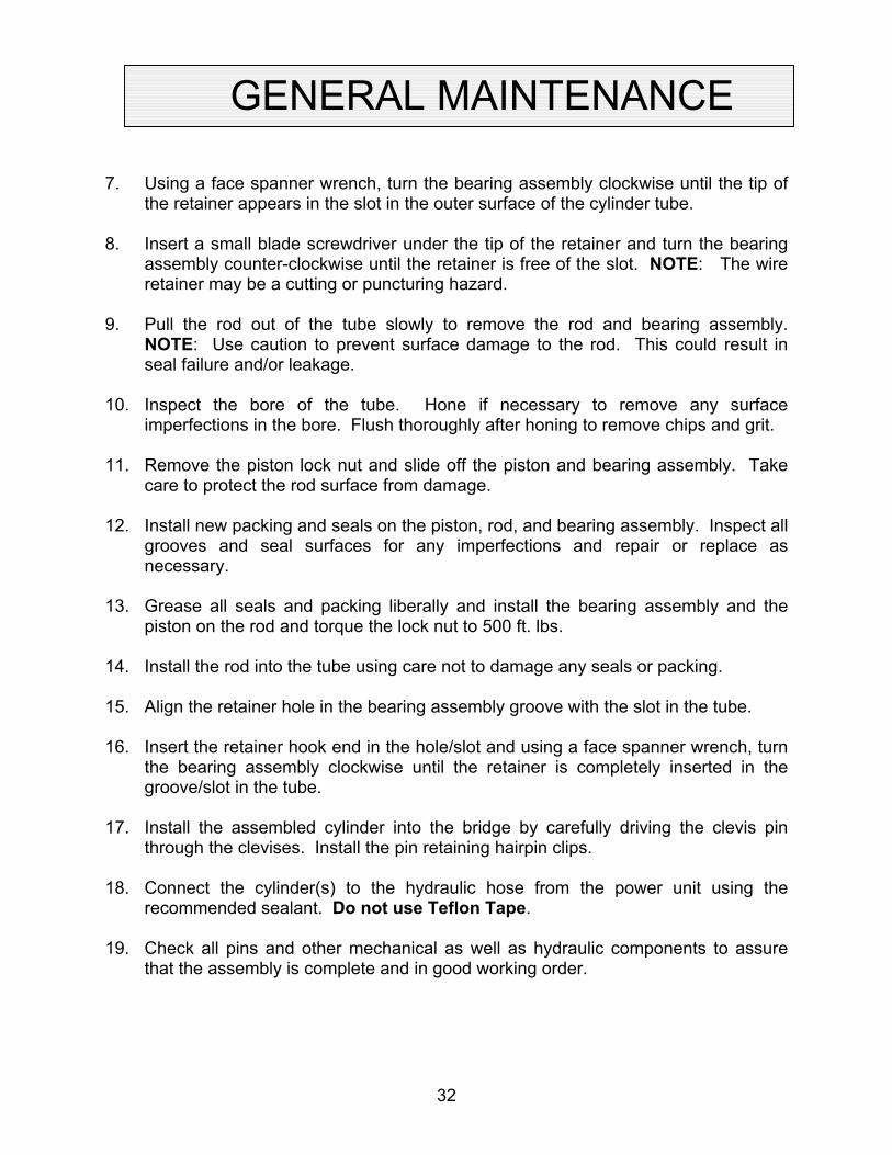
GENERAL MAINTENANCE 7. Using a face spanner wrench, turn the bearing assembly clockwise until the tip of
the retainer appears in the slot in the outer surface of the cylinder tube. 8. Insert a small blade screwdriver under the tip of the retainer and turn the bearing
assembly counter-clockwise until the retainer is free of the slot. NOTE: The wire retainer may be a cutting or puncturing hazard.
9. Pull the rod out of the tube slowly to remove the rod and bearing assembly.
NOTE: Use caution to prevent surface damage to the rod. This could result in seal failure and/or leakage.
10. Inspect the bore of the tube. Hone if necessary to remove any surface
imperfections in the bore. Flush thoroughly after honing to remove chips and grit. 11. Remove the piston lock nut and slide off the piston and bearing assembly. Take
care to protect the rod surface from damage. 12. Install new packing and seals on the piston, rod, and bearing assembly. Inspect all
grooves and seal surfaces for any imperfections and repair or replace as necessary.
13. Grease all seals and packing liberally and install the bearing assembly and the
piston on the rod and torque the lock nut to 500 ft. lbs. 14. Install the rod into the tube using care not to damage any seals or packing. 15. Align the retainer hole in the bearing assembly groove with the slot in the tube. 16. Insert the retainer hook end in the hole/slot and using a face spanner wrench, turn
the bearing assembly clockwise until the retainer is completely inserted in the groove/slot in the tube.
17. Install the assembled cylinder into the bridge by carefully driving the clevis pin
through the clevises. Install the pin retaining hairpin clips. 18. Connect the cylinder(s) to the hydraulic hose from the power unit using the
recommended sealant. Do not use Teflon Tape. 19. Check all pins and other mechanical as well as hydraulic components to assure
that the assembly is complete and in good working order.
32

GENERAL MAINTENANCE
20. Turn the electrical supply back on and press the “UP” button on the controller to
raise the bridge. NOTE: 15 to 30 seconds time may elapse to fill the empty cylinders before movement is noted.
21. Press the “DOWN” button on the controller to cycle the lift to the fully lowered
position. Hold the “DOWN” button 30 to 40 seconds to allow air in the cylinders to bleed back into the reservoir tank.
22. Cycle the bridge 10 to 15 times and repeat the bleeding operation by holding the
”DOWN” button for 30 to 40 seconds. 23. Check the oil level in the reservoir with the bridge in the fully lowered position. Add
as necessary (see “Routine Maintenance” for oil recommendations). 24. Clean the oil filler breather cap if it appears dirty. 25. Clean up any debris and or spilled oil from the area.
33

ROD ASS'YTUBE ASS'Y
LOCK NUT
WEAR RINGPISTON SEAL
O-RING
FOAM RING HEADWIPER
O-RINGWEAR RING
RETAINING RING
GENERAL MAINTENANCE
Figure 19 Hydraulic Cylinder
34

GENERAL MAINTENANCE
VELOCITY FUSE REPLACEMENT
DANGER!
Do not attempt to remove the velocity fuse until the bridge is securely supported with the blocking devices and all hydraulic pressure has been removed from the lifting cylinders and hydraulic hoses. Failure to follow these instructions could result in personal injury or death!
Never attempt to take a velocity fuse apart and repair it. These are precision devices that are factory assembled under exacting conditions. Velocity fuses should always be replaced. 1. The arrow on the exterior surface of the velocity fuse shows the direction of the
restriction to the oil flow. The arrow should always point away from the cylinder. 2. Do not use Teflon tape on the threaded connections of a velocity fuse. Tape
fragments can cause malfunctioning of the fuse. 3. Check all fitting connections for hydraulic leaks and tighten as necessary. HOSE ORIENTATION To prevent damage to the cylinder hose(s) and possible failure of bridge, it is necessary to establish a correct hose shape and pattern of movement as follows: 1. Lower the bridge and block securely. See “Blocking Instructions”. 2. Install one end of the new hose to the cylinder elbow fitting. 3. Raise the bridge carefully and check to see that the hose is free and clear of the
cylinder and other structured members. If not, twist the hose in the direction necessary to clear it of any obstruction and then lock the swivel fitting securely.
35

GENERAL MAINTENANCE
ROCK SALT It has been discovered that rock salt is being used to melt the ice and snow off of the platforms in the northern region and during the winter months. Rock salt will accelerate the deterioration of any paint. Therefore, Autoquip recommends the use of a synthetic “Ice Melt” product in lieu of rock salt. Warranty on the paint finish will be denied when it is suspected that rock salt has been used. Please contact the Product Support Team at Autoquip at 1-888-811-9876 or 405-282-5200.
36

GENERAL MAINTENANCE
REL
IEF
FILT
ER
CLE
VIS
MO
UN
TIN
G.
SPEC
IFIC
MO
DEL
.
DIS
PLAC
EMEN
T
SUC
TIO
N
PUM
PFI
XED
LIN
E
CH
ECK
VALV
E
FLO
W C
ON
TRO
L(B
RID
GE
LOW
ERIN
G
SPEE
D)
P
RES
ERVO
IR
AUTO
QU
IP)
(PR
ESET
AT
VALV
ET
SOL.
"B"
(RET
RAC
T)
SAFE
TY L
EG V
ALVE
(4-W
AY, 3
-PO
SITI
ON
,SP
RIN
G C
ENTE
RED
,D
OU
BLE
SOLE
NO
ID)
SAFE
TY L
EG R
AMS
- (2)
1 1
/2" B
OR
E,3/
4" D
IA. C
HR
OM
E PL
ATED
RO
DS,
3" S
TRO
KE, P
INEY
E M
OU
NTI
NG
.
A P
B T
(2) H
YDR
AULI
C W
IRE
BRAI
D H
OSE
S FR
OM
CYL
IND
ERS
TO O
IL L
INE.
FUR
NIS
HED
BY
AUTO
QU
IP.
CO
NN
ECTE
D B
Y IN
STAL
LER
.
CO
MPL
ETE
OIL
INFO
RM
ATIO
N W
ILL
BE IN
BASC
ULE
BR
IDG
E IN
STAL
LATI
ON
MAN
UAL
PRO
VID
ED A
T TI
ME
OF
BRID
GE
DEL
IVER
Y.O
IL B
Y IN
STAL
LER
.SOL.
"A"
(EXT
END
)
DO
WN
SO
L. V
ALVE
DO
WN
SO
L.
HYD
RAU
LIC
WIR
EBR
AID
HO
SES
FRO
M C
YLIN
DER
S TO
OIL
LIN
E. F
UR
NIS
HED
BY
AUTO
QU
IP.
CO
NN
ECTE
D B
Y IN
STAL
LER
.
HYD
RAU
LIC
CYL
IND
ERS
WIT
HC
HR
OM
E PL
ATED
RO
D,
QU
ANTI
TY D
EPEN
DS
ON
PUM
PM
OTO
R
M
Figure 20 Generic Hydraulic Schematic
37

GENERAL MAINTENANCE
20 20 20
T3 T2 T1
M
20 20
FUSE
D D
ISC
ON
NEC
T
(SH
OW
N T
RIP
PED
)
SAFE
TY L
EG F
ULL
YR
ETR
ACTE
D L
IMIT
SW
ITH
ES
ON
MAG
. STA
RTE
RAU
X. C
ON
TAC
T
STA.
#1
PUSH
BUTT
ON
SU
PPU
SHBU
TTO
NS
STA.
#1
2 2
STA.
#2
3
1712
22 2 2
7 13 18
SAFE
TY L
EG
SUPP
LYVO
LTAG
E
STA.
#2
GR
OU
ND
DO
WN
45
(BY
OTH
ERS)
#1 #2
19
89 14
LIM
IT S
WIT
CH
ESFU
LLY
EXTE
ND
ED
#1
MO
TOR
PUM
P
DO
WN
SO
L.
RET
. SO
L. "B
"
SAFE
TY L
EG
TRAS
FOR
MER
CO
NTA
CTS
MAG
NET
IC S
TAR
TER
(IF R
EQ'D
)BY
OTH
ERS
SOLE
NO
ID
FUSE
6
10
L3 L2 L1
EXTE
ND
SO
L. "A
"
L2
OVE
RLO
ADS
SFET
Y LE
GS
L1
LIM
IT S
WIT
CH
BRID
GE
POSI
TIO
N
15611
#2
11
OVE
RLO
ADS
THER
MAL
Figure 21 Generic Electrical Schematic
38

GENERAL MAINTENANCE
Figure 22 Pushbutton Assembly 39

QTY
1 M
1 M
1 P
1 C
1 P
2 ¼
1 S
1 D
D 1 D
1 F
REPLACEMENT PARTS LIST
POWER UNIT PARTS LIST
Description
Vertical Part No.
otor, 5 HP 208/230/460 Volt 3 PH straight shaft 30600449
otor Coupling, Lovejoy L-095, 1 1/8” bore 20000154
ump Coupling, Lovejoy L-095, 7/16” bore 20000030
oupling Rubber Spider 20000162
ump, straight shaft 40300162
” Dyna-Seal Washer for Deltatrol 45901014
ump Strainer 47700075
eltatrol Kit 41050880
own Solenoid, 24 VAC 32701380
own Solenoid, 115 VAC 32701370
iller/Breather Cap Assembly 47700208
40

TROUBLESHOOTING ANALYSIS
DANGER!
To avoid personal injury, NEVER go under the bridge or perform any maintenance until the load is removed and the bridge is securely blocked. See "Blocking Instructions" section.
PROBLEM POSSIBLE CAUSE AND SOLUTION Bridge does not raise. • The motor voltage/wiring may be incorrect.
• The hydraulic line or hose may be leaking. • Oil in the reservoir may be low. Add oil as
necessary (See the “Routine Maintenance” section.)
• The load may exceed the bridge rating. (See the “Specifications” section.)
• The suction screen may be clogged. Remove and clean the screen. Drain and replace the oil.
• The suction line may be leaking air due to a loose fitting. Tighten as needed.
• The breather holes in the reservoir fill plug may be clogged. Remove and clean.
• The "Down" valve may be energized by faulty wiring or stuck open. Remove the solenoid and check.
• The power unit pump may be defective • The structural members of the bridge may be in
a bind. • The manual lowering device may be engaged.
Bridge seems bouncy during operation.
• There may be air in the hydraulic system. Bleed the air from the cylinder
• Oil in the reservoir may be low. Add oil as
necessary (See the “Routine Maintenance” section.)
• The power unit suction strainer may be clogged.
• The power unit suction line may be leaking.
41

TROUBLESHOOTING ANALYSIS
PROBLEM POSSIBLE CAUSE AND SOLUTION Bridge will not lower. • The down solenoid may be malfunctioning.
• The structural members may be in a bind. • The tubing or hose is obstructed or broken. Check
for obstruction in the line. • The return filter may be clogged. • The velocity fuse may be locked. Do not attempt to
remove the velocity fuse. The following steps should be followed:
1. Inspect all fittings, hoses, and other hydraulic components for leads or damage. 2. If no leak or damage is noticed, attempt to pressurize the lifting cylinder by depressing the “UP” button on the controller for a few seconds. Immediately up releasing the “UP” button, depress the “DOWN” button. If the bridge starts to lower, continue pressing the “DOWN” button until the bridge is in the fully lowered position. 3. If the bridge does not lower after trying Step 2, wait approximately 10 – 15 minutes for the pressure in the hydraulic system to equalize. Momentarily press the “UP” button, then, depress the “DOWN” button until the bridge is in the fully lowered position. 4. Once the bridge is in the fully lowered position, bleed the air from the hydraulic system by depressing the “DOWN” button. Hold the “DOWN” button for approximately 60 seconds. This step may need to be repeated several times to fully remove the air in the system by raising the bridge to 50% of its travel and then lowering it.
• Should the above steps not correct the problem,
contact Autoquip to obtain instruction for further action.
42

PROBLEM POSSIBLE CAUSE AND SOLUTION Bridge raises slowly. • The structural members of the bridge may be
binding.
• The tubing or hose is obstructed or broken. Where pipe is used, check for obstruction in the line.
• The hydraulic line or hose may be leaking.
• The oil viscosity is not suited for the environmental
conditions. Refer to “Routine Maintenance” section for oil recommendations.
• Check the oil level in the reservoir.
• The motor voltage/wiring may be incorrect.
• The suction screen may be clogged. Remove and
clean the screen. Drain and replace the oil.
• The suction line may be leaking air due to a loose fitting. Tighten as needed.
• The breather holes in the reservoir fill plug may be
clogged. Remove and clean.
• The power unit pump may be defective.
Bridge lowers slowly.
• The structural members of the bridge is binding.
• The tubing or hose is obstructed or broken. Where pipe is used, check for obstruction in the line.
• The oil viscosity is not suited for the environmental
conditions. Refer to “Routine Maintenance” section for oil recommendations.
• The return filter may be clogged due to dirt or
damage.
TROUBLESHOOTING ANALYSIS
43

PROBLEM POSSIBLE CAUSE AND SOLUTION Bridge will not remain in raised position.
• The cylinder packing may be leaking.
• The pump or Deltatrol regulator is not seating.
• The pump or Deltatrol check valve is not seating.
• The hydraulic tubing, hose, or fitting is leaking oil. • The return filter may be clogged.
TROUBLESHOOTING ANALYSIS
44