upwindreport-121016072243-phpapp01
DESCRIPTION
Offshore WindTRANSCRIPT

v3_21895_UpWind Report_AttentionGraphDisparaissent.indd 104v3_21895_UpWind Report_AttentionGraphDisparaissent.indd 104 2/03/11 15:162/03/11 15:16
1 Design limits and solutions for very large wind turbines
UpWindDesign limits and solutions for very large wind turbines
A 20 MW turbine is feasible
March 2011
Supported by:
v3_21895_UpWind Report_AttentionGraphDisparaissent.indd 1v3_21895_UpWind Report_AttentionGraphDisparaissent.indd 1 2/03/11 15:152/03/11 15:15
March 20112
Photo
: N
ord
ex
v3_21895_UpWind Report_AttentionGraphDisparaissent.indd 2v3_21895_UpWind Report_AttentionGraphDisparaissent.indd 2 2/03/11 15:152/03/11 15:15

3 Design limits and solutions for very large wind turbines
Contents
1. UpWind: Summary - a 20 MW turbine is feasible ................................................................ 10
The need for the UpWind project: exploring the design limits of upscaling ........................................... 11
UpWind methodology: a lighthouse approach .................................................................................... 13
UpWind: 20 MW innovative turbine ................................................................................................... 14
UpWind: rooted in history ................................................................................................................ 16
UpWind: continuous innovation ........................................................................................................ 18
2. UpWind: Scientifi c integration ................................................................................................. 20
2.1 Work Package 1A1: Standards and integration .................................................................................. 22
Challenges and main innovations ........................................................................................................ 22
Results ............................................................................................................................................. 23
Subtask A: Reference wind turbine and cost model ........................................................................... 23
Subtask B: Integral design approach methodology ............................................................................. 23
Subtask C: Development of (pre)standards for the application of the integral design approach ............. 25
Subtask D: Integration, review and planning workshops ..................................................................... 26
References ........................................................................................................................................ 26
2.2. Work Package 1A2: Metrology ......................................................................................................... 27
Challenges and main innovations ........................................................................................................ 27
Results ............................................................................................................................................. 28
The metrology database .................................................................................................................. 28
Advances in metrology .................................................................................................................... 28
Verifi cation of anemometer calibrations ............................................................................................ 29
References ........................................................................................................................................ 31
2.3. Work Package 1A3: Training and education ...................................................................................... 32
Challenges and main innovations ........................................................................................................ 32
Results and conclusions ..................................................................................................................... 33
v3_21895_UpWind Report_AttentionGraphDisparaissent.indd 3v3_21895_UpWind Report_AttentionGraphDisparaissent.indd 3 2/03/11 15:152/03/11 15:15
March 20114
3. UpWind: Technology integration .............................................................................................. 36
3.1 Work Package 1B1: Innovative rotor blades (Innoblade)..................................................................... 38
Challenges and main innovations ........................................................................................................ 38
Results ............................................................................................................................................. 38
Blade aerodynamic design and load calculation ................................................................................. 38
Materials selection, structural design and structural verifi cation ......................................................... 39
Sensor monitoring with response actions.......................................................................................... 39
Blade joint ...................................................................................................................................... 40
References ........................................................................................................................................ 41
3.2 Work Package 1B2: Transmission and conversion .............................................................................. 44
Challenges and main innovations ........................................................................................................ 44
Results ............................................................................................................................................. 44
Mechanical transmission ................................................................................................................. 44
Generators ..................................................................................................................................... 46
Power electronics ............................................................................................................................ 47
3.3 Work Package 1B3: Smart rotor blades and rotor control ................................................................... 48
Challenges and main innovations ........................................................................................................ 48
Research activities and working methods ............................................................................................ 48
Task 1: Aerodynamic controls and aeroelastic modelling .................................................................... 49
Task 2: Smart structures ................................................................................................................. 49
Task 3: Control systems .................................................................................................................. 50
Task 4: Smart wind turbine wind tunnel model .................................................................................. 50
Task 5: Interfaces ........................................................................................................................... 51
References ........................................................................................................................................ 52
3.4 Work Package 1B4: Upscaling .......................................................................................................... 54
Challenges and main innovations ........................................................................................................ 54
Activities ........................................................................................................................................... 55
Contents
v3_21895_UpWind Report_AttentionGraphDisparaissent.indd 4v3_21895_UpWind Report_AttentionGraphDisparaissent.indd 4 2/03/11 15:152/03/11 15:15
5 Design limits and solutions for very large wind turbines
4. UpWind: Research activities .................................................................................................... 56
4.1 Work Package 2: Aerodynamics and aeroelastics .............................................................................. 58
Challenges and main innovations ........................................................................................................ 58
Research activities and results ........................................................................................................... 59
Structural dynamics — large defl ections and non-linear effects .......................................................... 59
Advanced aerodynamic models ........................................................................................................ 59
Aerodynamic and aeroelastic modelling of advanced control features and aerodynamic devices ............ 60
Aeroelastic stability and total damping prediction including hydroelastic interaction ............................. 60
Computation of aerodynamic noise .................................................................................................. 60
4.2 Work Package 3: Rotor structures and materials ............................................................................... 61
Challenges and main innovations ........................................................................................................ 61
Results ............................................................................................................................................. 62
Task 1: Applied (phenomenological) material model ........................................................................... 62
Task 3.2 Micro-mechanics-based material model ............................................................................... 63
Task 3.3: Damage-tolerant design concept ........................................................................................ 64
Task 3.4: Upscaling — cost factors .................................................................................................. 66
4.3 Work Package 4: Foundations and support structures........................................................................ 67
Challenges and main innovations ........................................................................................................ 67
Results ............................................................................................................................................. 69
Task 1: Integration of support structure and wind turbine design ........................................................ 69
Task 2: Support structure concepts for deep-water sites .................................................................... 70
Task 3: Enhancement of design methods and standards .................................................................... 71
References ........................................................................................................................................ 72
4.4 Work Package 5: Control systems ..................................................................................................... 74
Challenges and main innovations ........................................................................................................ 74
Results ............................................................................................................................................. 75
Supervisory control implications of advanced control ......................................................................... 75
Online estimation of mechanical load for wind turbines ...................................................................... 76
Dual pitch control for out-of-plane-blade load reduction ...................................................................... 77
Identifi cation of wind turbines operating in closed loop ...................................................................... 78
LIDAR-assisted collective pitch control .............................................................................................. 79
Validation of load reducing controllers in full-scale fi eld tests ............................................................. 80
Hardware-in-the-loop testing of pitch actuators .................................................................................. 81
Riding through grid faults ................................................................................................................. 82
Impact of the drive train on wind farm VAR Control ............................................................................ 82
References ........................................................................................................................................ 83
v3_21895_UpWind Report_AttentionGraphDisparaissent.indd 5v3_21895_UpWind Report_AttentionGraphDisparaissent.indd 5 2/03/11 15:152/03/11 15:15

March 20116
4.5 Work Package 6: Remote sensing ..................................................................................................... 84
Challenges and main innovations ........................................................................................................ 84
Results ............................................................................................................................................. 85
SODAR – calibration and design improvements ................................................................................. 85
LIDAR testing in fl at terrain .............................................................................................................. 86
LIDAR measurements in complex terrain ........................................................................................... 86
Power curve testing ......................................................................................................................... 86
IEC 61400-12-1 revision .................................................................................................................. 87
LIDAR turbulence measurements ..................................................................................................... 87
References ........................................................................................................................................ 88
4.6 Work Package 7: Condition monitoring .............................................................................................. 89
Challenges and main innovations ........................................................................................................ 89
Results ............................................................................................................................................. 90
Optimised condition monitoring systems for use in wind turbines of the next generation ...................... 90
“Flight leader” turbines for wind farms .............................................................................................. 90
Fault statistics ................................................................................................................................ 92
Standardisation .............................................................................................................................. 92
Conclusions ................................................................................................................................... 92
References. ....................................................................................................................................... 93
4.7 Work Package 8: Flow ...................................................................................................................... 94
Challenges and main innovations ........................................................................................................ 94
Results ............................................................................................................................................. 95
References ........................................................................................................................................ 97
4.8 Work Package 9: Electrical grid ........................................................................................................ 98
Challenges and main innovations ........................................................................................................ 98
Results ............................................................................................................................................. 99
Wind farm reliability ........................................................................................................................ 99
Power system requirements ........................................................................................................... 100
Wind farm electrical design and control .......................................................................................... 101
Upscaling ..................................................................................................................................... 102
Contents
v3_21895_UpWind Report_AttentionGraphDisparaissent.indd 6v3_21895_UpWind Report_AttentionGraphDisparaissent.indd 6 2/03/11 15:152/03/11 15:15

7 Design limits and solutions for very large wind turbines
Contract number: 019945 (SES6)
Duration: 60 months
Co-ordinator: Risø National Laboratory - DTU
Cover picture: www.iStockphoto.com
PROJECT PARTNERS:
Risø National Laboratory - DTU, Denmark (Risø - DTU), Project Coordinator
Aalborg University (AaU), Denmark
Energy Research Centre of the Netherlands (ECN), The Netherlands
Stichting Kenniscentrum Windturbine Materialen en Constructies (WMC), The Netherlands
Delft University of Technology (DUT), The Netherlands
Centre for Renewable Energy Sources (CRES), Greece
National Technical University of Athens (NTUA), Greece
University of Patras (UP), Greece
Institut für Solare Energieversorgungstechnik Verein an der Universität Kassel (ISET), Germany
Universität Stuttgart (Usttut), Germany
DONG Energy Power A/S (DONG), Denmark
Vattenfall Vindkraft A/S, Denmark
GE Wind Energy Zweigniederlassung der General Electric Deutschland Holding GmbH (GEGR-E), Germany
Gamesa Innovation and Technology (GIT), Spain
Fiberblade Eólica S.A., Spain
GL Garrad Hassan and Partners Ltd. (GL GH), United Kingdom
Werkzeugmaschinenlabor, Aachen University (RWTH – WZL), Germany
LM Glasfi ber A.S. (LM), Denmark
Germanischer Lloyd Windenergie GmbH (GL), Germany
Ramboll Danmark A.S.(Ramboll), Denmark
Fundación Robotiker (ROBOTIKER), Spain
VTT Technical Research Centre of Finland (VTT), Finland
SAMTECH S.A (SAMTECH), Belgium
Shell Windenergy BV (SHELL), The Netherlands
Repower Systems AG (REP), Germany
Bosch Rexroth AG (BRM-GT), Germany
Det Norske Veritas, Danmark A/S, Denmark
Lohmann und Stolterfoht GmbH, Germany
University of Edinburgh (UEDIN), United Kingdom
Instytut Podstawowych Problemow Techniki PAN (IPPT), Poland
Institute of Thermomechanics, Academy of Sciences of the Czech Republic (IT ACSR), Czech Republic
v3_21895_UpWind Report_AttentionGraphDisparaissent.indd 7v3_21895_UpWind Report_AttentionGraphDisparaissent.indd 7 2/03/11 15:152/03/11 15:15

March 20118
Lulea University of Technology (LTU), Sweden
Council for the Central Laboratory of the Research Councils (CCLRC), United Kingdom
Vrije Universiteit Brussels (VUB), Belgium
QinetiQ Ltd. (QinetiQ), United Kingdom
Vestas Asia Pacifi c A/S (Vestas APAC), Denmark
Smart Fibres Ltd. (SmartFibres), United Kingdom
University of Salford (USAL), United Kingdom
European Wind Energy Association (EWEA), Belgium
Ecotècnia S.C.C.L. (ECOTECNIA), Spain
Fundación CENER - CIEMAT, Spain
Fraunhofer-Institut fur Windenergie und Energiesystemtechnik (IWES), Germany
Institute for Superhard Materials of the National Academy of Sciences of Ukraine (ISM), Ukraine
Department of Civil Engineering, Thapar University (TIET), India
China University of Mining and Technology (Beijing), State Key Laboratory of Coal Resources and Mine
Safety (CUMTB), China
CWMT Fraunhofer (CWMT), Germany
SUPPORTED BY:
The Sixth Framework Programme for Research and Development of the European Commission (FP6)
EXECUTIVE SUMMARY AUTHORS:
Nicolas Fichaux, European Wind Energy Association
Jos Beurskens, Energy Research Centre of the Netherlands
Peter Hjuler Jensen, Risø National Laboratory – DTU
Justin Wilkes, European Wind Energy Association
Contents
v3_21895_UpWind Report_AttentionGraphDisparaissent.indd 8v3_21895_UpWind Report_AttentionGraphDisparaissent.indd 8 2/03/11 15:152/03/11 15:15

9 Design limits and solutions for very large wind turbines
WORK PACKAGES AUTHORS:
Nicolas Fichaux, European Wind Energy Association
Sten Frandsen, Risø National Laboratory – DTU
John Dalsgaard Sørensen, Aalborg University and Risø National Laboratory - DTU
Peter Eecen, Energy Research Centre of the Netherlands
Charalambos Malamatenios, Centre for Renewable Energy Sources
Joaquin Arteaga Gomez, Gamesa
Jan Hemmelmann, GE Global Research
Gijs van Kuik, Delft University of Technology
Bernard Bulder, Energy Research Centre of the Netherlands
Flemming Rasmussen, Risø National Laboratory – DTU
Bert Janssen, Energy Research Centre of the Netherlands
Tim Fischer, Universität Stuttgart
Ervin Bossanyi, GL Garrad Hassan and Partners
Mike Courtney, Risø National Laboratory – DTU
Jochen Giebhardt, Fraunhofer-Institut fur Windenergie und Energiesystemtechnik
Rebecca Barthelmie, Risø National Laboratory – DTU
Ole Holmstrøm, DONG Energy
SPECIAL CONTRIBUTION OF:
Dorina Iuga, European Wind Energy Association
Sharon Wokke, European Wind Energy Association
EDITING:
Sarah Azau, European Wind Energy Association
Chris Rose, European Wind Energy Association
Design and production: De Visu Digital Document Design
Design coordinator: Raffaella Bianchin, European Wind Energy Association
Published in March 2011
LEGAL NOTICE:
Neither the European Commission nor any person acting on behalf of the Commission is
responsible for the use which might be made of the following information.
The views expressed in this publication are the sole responsibility of the author and do not
necessarily refl ect the views of the European Commission.
v3_21895_UpWind Report_AttentionGraphDisparaissent.indd 9v3_21895_UpWind Report_AttentionGraphDisparaissent.indd 9 2/03/11 15:152/03/11 15:15

March 201110
xxx
UPWIND: SUMMARYA 20 MW TURBINE IS FEASIBLE1
Photo
: Stiftu
ng O
ffshore
Energ
ie/D
. Gehrin
v3_21895_UpWind Report_AttentionGraphDisparaissent.indd 10v3_21895_UpWind Report_AttentionGraphDisparaissent.indd 10 2/03/11 15:152/03/11 15:15

11 Design limits and solutions for very large wind turbines
The need for the UpWind project:
exploring the design limits of
upscaling
The key objective of the European wind industry‘s
research and development strategy for the next ten
years is to become the most competitive energy source
by 2020 onshore and offshore by 2030 1, without
accounting for external costs.
In October 2009, the European Commission published
its Communication “Investing in the Development of
Low Carbon Technologies (SET-Plan)”, stating that wind
power would be “capable of contributing up to 20% of
EU electricity by 2020 and as much as 33% by 2030”
were the industry‘s research needs fully met. The wind
industry agrees with the Commission‘s assessment.
Signifi cant additional research efforts in wind energy
are needed to bridge the gap between the 5% of the
European electricity demand which is currently covered
by wind energy, and one-fi fth of electricity demand in
2020, one-third in 2030 and half by 2050.
Meeting the European Commission‘s ambitions for wind
energy would require meeting EWEA‘s high scenario of
265 GW of wind power capacity, including 55 GW of
offshore wind by 2020. The Commission‘s 2030 target
of 33% of EU power from wind energy can be reached by
meeting EWEA‘s 2030 installed capacity target of 400
GW wind, 150 GW of which would be offshore. Up to
2050 a total of 600 GW of wind energy capacity would
be envisaged, 250 GW would be onshore and 350 GW
offshore. Assuming a total electricity demand of 4,000
TWh in 2050 this amount of installed wind power could
produce about 2,000 TWh and hence meet 50% of the
EU‘s electricity demand.
Thus a signifi cant part of the required future installed
wind power will be located offshore. For offshore ap-
plication new technologies and know how are needed
beyond the existing knowledge base, which is mainly fo-
cused on onshore applications. Going offshore implies
not only new technologies but also upscaling of wind
turbine dimensions, wind farm capacities and required
– not yet existing – electrical infrastructure. The need
for upscaling found its origin in the cost structure of off-
shore installations and is the “motor” of modern wind
energy research. The results will not be applicable to
offshore wind energy technology only, but will also lead
to more cost effective onshore installations.
Ultimately, all research activities, aside from other im-
plementation measures, are focused on reductions to
the cost of energy. The industry is taking two pathways
towards cost reductions in parallel:
Incremental innovation: cost reductions through
economies of scale resulting from increased market
volumes of mainstream products, with a continuous
improvement of the manufacturing and installation
methods and products;
Breakthrough innovation: creation of innovative prod-
ucts, including signifi cantly upscaled dedicated (off-
shore) turbines, to be considered as new products.
The UpWind project explores both innovation pathways.
In formulating the UpWind project the initiators realised
that wind energy technology disciplines were rather
fragmented (no integrated verifi ed design methods
were available), that essential knowledge was still miss-
ing in high priority areas (e.g. external loads), measur-
ing equipment was still not accurate or fast enough,
and external factors were not taken into consideration
in minimising cost of energy (grid connection, founda-
tions, wind farm interaction).
1 http://www.ewea.org/fi leadmin/ewea_documents/documents/publications/EWI/EWI_2010_fi nal.pdf
“ They did not know it was impossible, so they did it.”Mark Twain, American novelist, 1835 - 1910
v3_21895_UpWind Report_AttentionGraphDisparaissent.indd 11v3_21895_UpWind Report_AttentionGraphDisparaissent.indd 11 2/03/11 15:152/03/11 15:15

March 201112
1 UpWind: summary - A 20 MW turbine is feasible
In order to be able to address all shortcomings in an
effective way a comprehensive matrix project structure
was designed, where disciplinary, scientifi c integration
and technology integration were included (see page 18).
A key issue for integrating various research results was
developing an overall engineering cost model.
This unique UpWind approach quantifi es the contribu-
tion of the different types of innovation resulting from
the project. Not only are upscaling parameters incor-
porated, but also innovation effects are defi ned as a
separate independent parameter. At the time of writing
the full results of the integration process through cost
modelling was not yet available, but will be published in
2011. However, some early conclusions may already be
drawn, such as the benefi ts of distributed aerodynamic
blade control.
The question often arises whether there is one single
“optimum” technology. UpWind did not seek to defi ne
one unique optimum technology but rather explored var-
ious high-potential solutions and integrated them with
respect to the potential reduction of cost of energy. An
optimised wind turbine is the outcome of a complex
function combining requirements in terms of effi ciency
(electricity production), reliability, access, transport and
storage, installation, visibility, support to the electricity
network, noise emission, cost, and so on.
UpWind‘s focus was the wind turbine as the essential
component of a wind electricity plant. Thus external con-
ditions were only investigated if the results were needed
to optimise the turbine confi guration (e.g. grid connec-
tion options) and the other way around (control options
for wind turbines) in order to optimise wind farms.
UpWind did not seek the optimal wind turbine size, but
investigated the limits of upscaling, up to, approxima-
tely, 20 MW / 250 m rotor diameter. Looking at very
large designs, attention is focused on physical phenom-
ena or model behaviour that are relevant for large-scale
structures but have negligible effects at lower scales.
For instance, the development of control methods for
very large rotors requires the full wind behaviour, includ-
ing wind shear and turbulence, to be taken into account.
This in turn means the anemometer values must be
corrected based on the rotor effects and therefore ad-
vanced wind measurement technologies need to be
used. UpWind therefore developed and validated the
measurement devices and models able to provide such
measurements (LIDAR).
UpWind also developed the tools and specifi ed the
methods to enable large designs. These tools and
methods are available to optimise today‘s designs,
and are used to improve the reliability and effi ciency of
current products, such as drive trains.
UpWind demonstrates that a 20 MW design is feasible.
No signifi cant problems have been found when upscal-
ing wind turbines to that scale, provided some key
innovations are developed and integrated. These innova-
tions come with extra cost, and the cost / benefi t ratio
depends on a complex set of parameters. The project
resulted for instance in the specifi cation of mass /
strength ratios for future very large blades securing the
same load levels as the present generation wind tur-
bines. Thus in principle, future large rotors and other
turbine components could be realised without cost in-
creases, assuming the new materials are within certain
set cost limits.
As the UpWind project‘s scope is very wide and
the project has laid the basis for essential future
strategies for decreasing cost of energy, UpWind
contributed considerably to the recommendations
of the European Wind Energy Technology Plat-
form and the foundation for the European Wind
Initiative. It is clear from the conclusions of Up-
Wind that the European Wind Initiative‘s research
agenda is both feasible and necessary and should
therefore be fi nanced without delay by the Euro-
pean Commission, national governments and the
European wind energy sector.
v3_21895_UpWind Report_AttentionGraphDisparaissent.indd 12v3_21895_UpWind Report_AttentionGraphDisparaissent.indd 12 2/03/11 15:152/03/11 15:15

13 Design limits and solutions for very large wind turbines
UpWind methodology –
a lighthouse approach
For its assessment of the differences between the pa-
rameters of the upscaled wind turbine, UpWind adopt-
ed a reference 5 MW wind turbine. This reference was
based on the IEA reference turbine developed by the
National Renewable Energy Laboratory's (NREL). As
a fi rst step, this reference design was extrapolated
(“upscaled”) to 10 MW. The 20 MW goal emerged
progressively during the project, while the industry in
the meantime worked on larger machines. The largest
concepts which are now on the drawing board measure
close to 150 m rotor diameter and have an installed
power capacity of 10 MW. While a 10 MW concept pro-
gressively took shape, UpWind set its mind to a larger
wind turbine, a turbine of about 250 m rotor diameter
and a rated power of 20 MW. Also the idea of the
lighthouse concept was adopted to present the many
results of UpWind in one image.
The lighthouse concept is a virtual concept design of
a wind turbine in which promising innovations, either
mature or embryonic, are incorporated. The lighthouse
is not a pre-design of a wind turbine actually to be
realised, but a concept from which ideas can be drawn
for the industry’s own product development. One of the
innovations, for example, is a blade made from thermo-
plastic materials, incorporating distributed blade control,
including a control system, the input of which is partly
fed by LIDARs.
The 20 MW concept provides values and behaviour used
as model entries for optimisation. It is a virtual 20 MW
turbine, which could be designed with the existing tools,
without including the UpWind innovations. This extrapo-
lated virtual 20 MW design was unanimously assessed
as almost impossible to manufacture, and uneconomic.
The extrapolated 20 MW design would weigh 880 tonnes
on top of a tower making it impossible to store today at
a standard dockside, or install offshore with the current
installation vessels and cranes.
2 IEC 61400 class IB is an average wind speed at hub height of 10 m/s, V50 extreme gusts 70 m/s, 16% characteristic turbulence,
wind shear exponent is 0.2.
Reference wind
turbine 5 MW
Extrapolated
turbine 10 MW
Extrapolated virtual turbine
20 MW
Rating MW 5.00 10.00 20.00
Wind regime IEC class 1B 2 IEC class 1B IEC class 1B
No of blades 3 3 3
Rotor orientation Upwind Upwind Upwind
ControlVariable speed,
control pitch
Variable speed,
control pitch
Variable speed,
control pitch
Rotor diameter M 126 178 252
Hub height M 90 116 153
Max. rotor speed Rpm 12 9 6
Rotor mass Tones 122 305 770
Tower top mass Tones 320 760 880
Tower mass Tones 347 983 2,780
Theoretical electricity
productionGWh 369 774 1,626
v3_21895_UpWind Report_AttentionGraphDisparaissent.indd 13v3_21895_UpWind Report_AttentionGraphDisparaissent.indd 13 2/03/11 15:152/03/11 15:15

March 201114
1 UpWind: summary - A 20 MW turbine is feasible
The support structures able to carry such mass placed
at 153 m height are not possible to mass manufacture
today. The blade length would exceed 120 m, making
it the world‘s largest ever manufactured composite ele-
ment, which cannot be produced as a single piece with
today‘s technologies. The blade wall thickness would
exceed 30 cm, which puts constraints on the heating of
inner material core during the manufacturing process.
The blade length would also require new types of fi bres
to resist the loads.
However, the UpWind project developed innovations to
enable this basic design to be signifi cantly improved,
and therefore enable a potentially economically sound
design.
UpWind: 20 MW innovative turbine
Key weaknesses of the extrapolated virtual 20 MW de-
sign are the weight on top of the tower, the correspond-
ing loads on the entire structure and the aerodynamic
rotor blade control. The future large-scale wind turbine
system drawn up by the UpWind project, however, is
smart, reliable, accessible, effi cient and lightweight.
A part of UpWind (WP3) 3 analysed wind turbine materi-
als. This enabled the micro-structure of the blade ma-
terials to be studied and optimised in order to develop
stronger and lighter blades. However, this would not be
suffi cient unless fatigue loading is also reduced.
Reducing fatigue loading means longer and lighter
blades can be built. The aerodynamic and aeroelastic
qualities of the models were signifi cantly improved
within the UpWind project, for example by integrat-
ing the shear effect over large rotors WP2. Signifi cant
knowledge was gained on load mitigation and noise
modelling.
UpWind demonstrated that advanced blade designs
could alleviate loads by 10%, by using more fl exible
materials and fore-bending the blades (WP2).
After reducing fatigue loads and applying materials with
a lower mass to strength ratio, a third essential step
is needed. The application of distributed aerodynamic
blade control, requiring advanced blade concepts with
integrated control features and aerodynamic devices.
Fatigue loads could be reduced 20-40% (WP2). Various
devices can be utilised to achieve this, such as trail-
ing edge fl aps, (continuous) camber control, synthetic
jets, micro tabs, or fl exible, controllable blade root cou-
pling. Within UpWind, prototypes of adapting trailing
edges, based on piezo electrically deformable materi-
als and SMA (shape memory alloys) were demonstrat-
ed (WP1B.3). However, the control system only works
if both hardware and software are incorporated in the
blade design. Thus advanced modelling and control al-
gorithms need to be developed and applied. This was
investigated in WP1B3.
Further reducing the loads requires advanced rotor con-
trol strategies (WP5) for “smart” turbines. These con-
trol strategies should be taken into account in the de-
sign of offshore support structures (WP4). The UpWind
project demonstrated that individual pitching of the
blades could lower fatigue loads by 20-30%. Dual pitch
as the fi rst step towards a more continuous distributed
blade control (pitching the blade in two sections) could
lead to load reductions of 15%. In addition, the future
smart turbine will use advanced features to perform
site adaptation of its controller in order to adapt to
local conditions (WP5).
Advanced control strategies are particularly relevant
for large offshore arrays, where UpWind demonstrated
that 20% of the power output can be lost due to wake
effects between turbines.
Optimised wind farm layouts were proposed, and inno-
vative control strategies were developed, for instance
lowering the power output of the fi rst row (thus making
these wind turbines a bit more transparent for the air
fl ow), facing the undisturbed wind, allowing for higher
overall wind farm effi ciency (WP8).
3 The reference WP in brackets refers to the specifi c ‘work package’ or sub-programme fi che provided within this report.
v3_21895_UpWind Report_AttentionGraphDisparaissent.indd 14v3_21895_UpWind Report_AttentionGraphDisparaissent.indd 14 2/03/11 15:152/03/11 15:15
15 Design limits and solutions for very large wind turbines
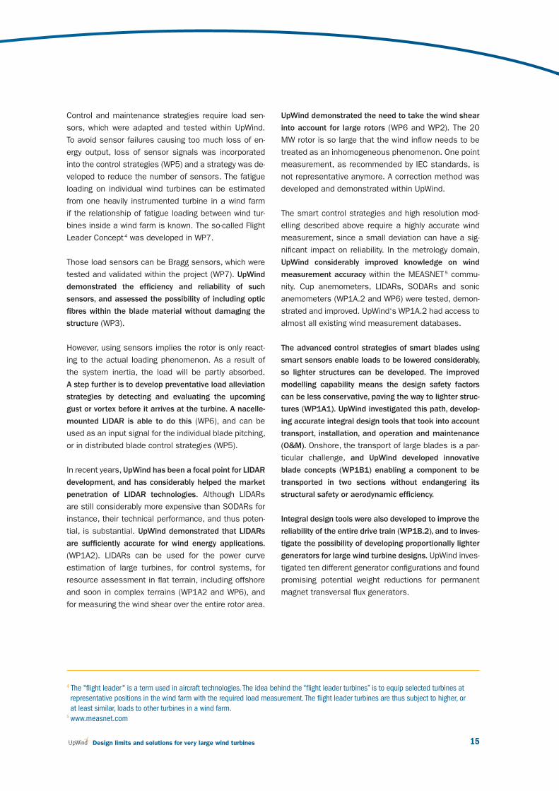
Control and maintenance strategies require load sen-
sors, which were adapted and tested within UpWind.
To avoid sensor failures causing too much loss of en-
ergy output, loss of sensor signals was incorporated
into the control strategies (WP5) and a strategy was de-
veloped to reduce the number of sensors. The fatigue
loading on individual wind turbines can be estimated
from one heavily instrumented turbine in a wind farm
if the relationship of fatigue loading between wind tur-
bines inside a wind farm is known. The so-called Flight
Leader Concept 4 was developed in WP7.
Those load sensors can be Bragg sensors, which were
tested and validated within the project (WP7). UpWind
demonstrated the effi ciency and reliability of such
sensors, and assessed the possibility of including optic
fi bres within the blade material without damaging the
structure (WP3).
However, using sensors implies the rotor is only react-
ing to the actual loading phenomenon. As a result of
the system inertia, the load will be partly absorbed.
A step further is to develop preventative load alleviation
strategies by detecting and evaluating the upcoming
gust or vortex before it arrives at the turbine. A nacelle-
mounted LIDAR is able to do this (WP6), and can be
used as an input signal for the individual blade pitching,
or in distributed blade control strategies (WP5).
In recent years, UpWind has been a focal point for LIDAR
development, and has considerably helped the market
penetration of LIDAR technologies. Although LIDARs
are still considerably more expensive than SODARs for
instance, their technical performance, and thus poten-
tial, is substantial. UpWind demonstrated that LIDARs
are suffi ciently accurate for wind energy applications.
(WP1A2). LIDARs can be used for the power curve
estimation of large turbines, for control systems, for
resource assessment in fl at terrain, including offshore
and soon in complex terrains (WP1A2 and WP6), and
for measuring the wind shear over the entire rotor area.
UpWind demonstrated the need to take the wind shear
into account for large rotors (WP6 and WP2). The 20
MW rotor is so large that the wind infl ow needs to be
treated as an inhomogeneous phenomenon. One point
measurement, as recommended by IEC standards, is
not representative anymore. A correction method was
developed and demonstrated within UpWind.
The smart control strategies and high resolution mod-
elling described above require a highly accurate wind
measurement, since a small deviation can have a sig-
nifi cant impact on reliability. In the metrology domain,
UpWind considerably improved knowledge on wind
measurement accuracy within the MEASNET 5 commu-
nity. Cup anemometers, LIDARs, SODARs and sonic
anemometers (WP1A.2 and WP6) were tested, demon-
strated and improved. UpWind‘s WP1A.2 had access to
almost all existing wind measurement databases.
The advanced control strategies of smart blades using
smart sensors enable loads to be lowered considerably,
so lighter structures can be developed. The improved
modelling capability means the design safety factors
can be less conservative, paving the way to lighter struc-
tures (WP1A1). UpWind investigated this path, develop-
ing accurate integral design tools that took into account
transport, installation, and operation and maintenance
(O&M). Onshore, the transport of large blades is a par-
ticular challenge, and UpWind developed innovative
blade concepts (WP1B1) enabling a component to be
transported in two sections without endangering its
structural safety or aerodynamic effi ciency.
Integral design tools were also developed to improve the
reliability of the entire drive train (WP1B.2), and to inves-
tigate the possibility of developing proportionally lighter
generators for large wind turbine designs. UpWind inves-
tigated ten different generator confi gurations and found
promising potential weight reductions for permanent
magnet transversal fl ux generators.
4 The "fl ight leader " is a term used in aircraft technologies. The idea behind the “fl ight leader turbines” is to equip selected turbines at
representative positions in the wind farm with the required load measurement. The fl ight leader turbines are thus subject to higher, or
at least similar, loads to other turbines in a wind farm.5 www.measnet.com
v3_21895_UpWind Report_AttentionGraphDisparaissent.indd 15v3_21895_UpWind Report_AttentionGraphDisparaissent.indd 15 2/03/11 15:152/03/11 15:15

March 201116
The UpWind project worked on ensuring the reliability of
large turbines, in particular for far offshore applications.
UpWind focused on condition monitoring technologies
(WP7) and fault prediction systems. Such advanced sys-
tems enable fault detection and preventative mainte-
nance to be carried out, with a large potential for cutting
O&M costs. The reliability of the future large blades can
be assessed using probabilistic blade failure simulation
tools (WP3).
Reducing the loads and the nacelle weight enables the
offshore substructure design to be optimised (WP4).
UpWind developed integrated wind turbine/substructure
design tools and investigated optimal offshore substruc-
ture confi gurations according to the type of turbine, type
of soil and water depth. Future deeper water locations
were investigated and innovative cost-effective designs
were analysed.
Progress was made on deep water foundation analy-
sis, including the development of advanced model-
ling techniques and enhancements of current design
standards which for example become very important
for fl oating designs.
With the improved intelligence of wind turbines, wind
farms are operated more and more as power plants,
providing services to the electricity system, such as
fl exibility and controllability of active and reactive power,
frequency and voltage, fault-ride-through or black start
capabilities (WP9). Those capabilities will allow for sub-
stantially increased penetration of wind power in the
grid in the near future. The future large offshore wind
farms, far from shore, will be connected to HVDC VSC,
forming the backbone of an integrated European off-
shore grid, and supporting the emergence of a single
electricity market.
It will be challenging for the wind energy sector to at-
tract and train the required number of engineers, post-
graduates and PhD students to fulfi l its needs. UpWind
focused on training and education (WP1A3), and devel-
oped free of charge advanced training modules on wind
energy, including the latest innovations in the fi eld. This
content is distributed through the REnKnow database 6.
UpWind: rooted in history
UpWind is the largest-ever EU-funded research and
development project on wind energy. In terms of scope,
content and volume, the project can be compared to
typical national R&D programmes carried out in coun-
tries like Denmark, Spain, the Netherlands and the
USA. The UpWind project was made up of 48 partners,
all leaders in their fi eld, half from the private sector,
and half from the research and academic sector. This
makes UpWind the largest public/private partnership
ever designed for the wind energy sector.
The story of the UpWind project starts in 2001. At
that time, the 2001 renewable electricity directive
(2001/77/EC) was facilitating the rapid growth of wind
energy in Europe. By the end of 2000, the installed wind
capacity in Europe was 13 GW. Growth was based on
1 to 2 MW wind turbines, the work horses of that time,
and demonstrators of 4 to 5 MW were under develop-
ment, showing the potential for upscaling and innova-
tion. Large cost reductions were envisaged. However,
the wind energy sector needed to considerably acceler-
ate its innovation rate if the energy objectives were to
be achieved.
1 UpWind: summary - A 20 MW turbine is feasible
6 http://www.renknow.net/
v3_21895_UpWind Report_AttentionGraphDisparaissent.indd 16v3_21895_UpWind Report_AttentionGraphDisparaissent.indd 16 2/03/11 15:152/03/11 15:15

17 Design limits and solutions for very large wind turbines
An innovation accelerator was required that could set
clear pathways for future development and rapidly
transfer technological advances to the market. In or-
der to shape such a vehicle, the wind industry created
what was known as a ‘ Wind Energy Thematic Network ’
(WEN), an initiative supported as a project by the Euro-
pean Commission. Through an extended consultation
process, WEN identifi ed the key innovation areas and
put forward recommendations to address the declin-
ing public R&D funding in the wind energy sector. The
WEN placed wind energy innovation in the context of
the newly adopted Lisbon strategy for the fi rst time 7 :
wind energy was identifi ed as being able to improve
European competitiveness.
In 2005 WEN published a roadmap for innovation, which
was the fi rst Strategic Research Agenda for the wind
energy sector. This document was used as a basis for
the European Wind Energy Technology Platform. TPWind
updated the Strategic Research Agenda and developed
an industry-led master plan with a total R&D budget of
€6 billion up to 2020: the European Wind Industrial Ini-
tiative (EWI). The recently created European Energy Re-
search Alliance (EERA) reinforces this trend by putting
more emphasis on long-term research. The UpWind pro-
posal and consortium, fi nanced by the European Com-
mission under the sixth Framework Programme (FP6),
was developed in parallel with the creation of the Tech-
nology Platform by the sector involving individual key
institutions and companies with the European Academy
of Wind Energy (EAWE) and the European Wind Energy
Association (EWEA) as essential catalysers. Building on
UpWind‘s achievements, EERA and EWI together cover
the main road of designing the European wind energy
technology of the future and helping to meet the EU‘s
2020 renewable energy targets, and beyond.
7 One objective was a level of spending of 3% of the EU GDP in R&D in 2010. The Lisbon objective was not achieved,
and the strategy was relaunched through the recent Europe 2020 strategy.
2008
250 m Ø
15 m Ø
112 m Ø
Roto
r dia
mete
r (m
)
Airbus A380
wing span
80m
126 m Ø
126 m Ø
160 m Ø
?
'85 '87 '89 '91 '93 '95 '97 '99 '01 '03 '05 '10 ? 1ST year of operation
.05 .3 .5 1.3 1.6 2 4.5 5 7.5 8/10 rated capacity (MW)
v3_21895_UpWind Report_AttentionGraphDisparaissent.indd 17v3_21895_UpWind Report_AttentionGraphDisparaissent.indd 17 2/03/11 15:152/03/11 15:15

March 201118
UpWind: continuous innovation
UpWind is one of the few integrated projects launched
under FP6. Integrated projects were designed to cover
the whole research spectrum. Due to the broad range
of innovation challenges to be covered in a single
fi eld, such projects required a high level of coordina-
tion and consistency. Due to their size and complexity,
high demands were put on the management. An inno-
vative management concept was designed, enabling
research to be carried out on specifi c issues, both sci-
entifi c and technological ones, while at the same time
integration of the results was guaranteed.
These considerations led to a matrix structure shown
below. In this structure, scientifi c and technical disci-
plines are dealt with within horizontal work packages
(WP‘s), and integration through vertical activities.
The vertical activities are themselves grouped into
scientifi c and technology integration work WP‘s re-
spectively. The earlier mentioned lighthouse approach 8
forms the focus of the WP1A.1 Integrated Design
Approach and Standards and WP1B.4 Upscaling.
All other WPs provide inputs.
1 UpWind: summary - A 20 MW turbine is feasible
8 UpWind investigated a lighthouse vision, which means a vision that defi nes the options and necessities for future very large wind
turbines.
WP Number
Work Package
2 Aerodynamics and aero-elastics
3 Rotor structure and materials
4 Foundations and support structures
5 Control systems
6 Remote sensing
7 Condition monitoring
8 Flow
9 Electrical grid
10 Management
1A1 1A3 1B1 1B2 1B3 1B4
Integrated
des
ign ap
proa
ch
and
stand
ards
Scientifi c integration Technology integration
Metrology
Training
and
edu
catio
n
Inno
vativ
e rotor b
lade
s
Tran
smission
and
con
version
Smar
t rotor blade
s
Upsc
aling
1A2
v3_21895_UpWind Report_AttentionGraphDisparaissent.indd 18v3_21895_UpWind Report_AttentionGraphDisparaissent.indd 18 2/03/11 15:152/03/11 15:15

19 Design limits and solutions for very large wind turbines
In addition to defi ning a clear way forward for wind
energy technology, UpWind had the responsibility of
accelerating innovation within the sector. This required
strong involvement from the private sector. The involve-
ment in UpWind of leading wind turbine and component
manufacturers, as well as software providers, techni-
cal consultants and energy companies, demonstrated
the sector‘s high level of maturity. Handling Intellectual
Property within large EU-funded projects was secured
by IP agreements and was dealt with inside the WP
concerned. This proved to be a very effective model.
The strategy followed by UpWind was to focus on innova-
tion with a long-term aim: exploring the design limits of
very large-scale wind turbines, in the 10-20 MW range.
UpWind used upscaling as a driver for innovation, and
moved away from the competitive arena. Along the way,
the challenges dealt with in UpWind became a reality,
with the demonstration of 5 MW turbines, the current
testing of 7 MW machines, and the development of
10 MW designs. The innovation developed within the
project helped solve day-to-day challenges, such as
was the case in the fi eld of WP1B.2 Transmission and
Conversion. UpWind had an international impact,
through the IEA Wind Implementing agreement, where
the UpWind results are included in several internation-
al task activities. Partnerships, especially in the fi eld
of material research (WP3), were developed with India,
Ukraine and China.
In terms of project fi nancing, UpWind shows the way
forward for public-private partnership instruments.
The scale of today‘s challenges, and the scarcity of
resources require developing innovative funding instru-
ments able to create a leverage effect. Those should
combine funding from the Framework Programmes,
other Community programmes and Member States,
private capital, and European Investment Bank instru-
ments. The future FP8 instruments are likely to be fl ex-
ible, with less red tape, and their structure is likely
to be shaped by the time-to-market of innovation, and
able to combine those various sources of funding in
a coordinated manner. Although UpWind was fi nanced
under the FP6, some specifi c WP activities were
co-fi nanced by Member State programmes beyond the
fi nancial scope of UpWind. One outstanding example is
the development of LIDAR remote sensing techniques
(WP6). This made UpWind the fi rst project within the
European Wind Initiative priorities that complemented
support from the Framework Programmes with coordi-
nated calls for proposals from committed countries.
Within EWI, UpWind is used as a reference case for
such instruments.
v3_21895_UpWind Report_AttentionGraphDisparaissent.indd 19v3_21895_UpWind Report_AttentionGraphDisparaissent.indd 19 2/03/11 15:152/03/11 15:15

March 201120
xxxxxxxxxxxxxxxx xxxxxxPhoto
: Vesta
s
UPWIND: SCIENTIFIC INTEGRATION2
v3_21895_UpWind Report_AttentionGraphDisparaissent.indd 20v3_21895_UpWind Report_AttentionGraphDisparaissent.indd 20 2/03/11 15:152/03/11 15:15

21 Design limits and solutions for very large wind turbines
UpWind: Scientifi c integration
1A1 Standards and integration
1A2 Metrology
1A3 Training and education
WP Number
Work Package
2 Aerodynamics and aero-elastics
3 Rotor structure and materials
4 Foundations and support structures
5 Control systems
6 Remote sensing
7 Condition monitoring
8 Flow
9 Electrical grid
10 Management
1A1 1A3 1B1 1B2 1B3 1B4
Integrated
des
ign ap
proa
ch
and stan
dards
Scientifi c integration Technology integration
Metrology
Inno
vativ
e rotor b
lade
s
Tran
smission
and
con
version
Smar
t rotor blade
s
Upsc
aling
1A2
Training
and
edu
catio
n
v3_21895_UpWind Report_AttentionGraphDisparaissent.indd 21v3_21895_UpWind Report_AttentionGraphDisparaissent.indd 21 2/03/11 15:162/03/11 15:16

March 201122
2.1 Work Package 1A1:
Standards and integration
Mr. Sten Frandsen from RisøNational Laboratory - DTU
died during the month of October 2010. He was the Work
Package leader of WP 1A1.
The entire UpWind consortium would like to acknowledge
the human and scientifi c abilities he demonstrated along
his career. Mr. Frandsen was known as a man express-
ing and standing for his ideas and his contribution to the
UpWind project was invaluable.
UpWind demonstrates that an integral design ap-
proach can signifi cantly cut costs for current and up-
scaled products. UpWind was trying to fi nd an optimal
wind turbine design: cost-effective and with appropri-
ate design safety levels, infl uenced by operation and
maintenance and installation strategies.
Challenges and main
innovations
The UpWind project needed a baseline case study to
benchmark innovation. UpWind defi ned a reference
5 MW turbine, adapted from NREL’s 5 MW design.
During the project, these reference design parameters
were extrapolated to a virtual 20 MW machine. This
enables a comparison to be made between a virtual
extrapolated 20 MW machine and the UpWind innova-
tive 20 MW machine. A cost model was developed in
order to isolate and study the dimensioning cost pa-
rameters of this upscaled wind turbine. However, as an
optimal design should account for the external design
constraints, an innovative design approach was devel-
oped that includes both technical and non-technical
disciplines within the same framework. In this frame-
work, manufacturing, transport, installation and O&M
procedures become design parameters rather than
constraints. It enables the system as a whole to be
optimised at a design stage. Finally, a large potential
for cost optimisation lies in the design safety levels.
A probabilistic design of structural wind turbine com-
ponents can be used to design components directly,
thereby ensuring the design is more uniform and eco-
nomic than that obtained by traditional design using
standards such as the IEC 61400 series.
The challenge is to effi ciently update the design stand-
ards and to promote the use of an integrated design
approach. This will ensure consistency between the
advanced models and strengthen their integration into
wind energy technology, improve the test methods and
design concepts developed in UpWind and in turn pro-
vide a consistent scientifi c background for standards
and design tools. The approach has four parts:
Providing a reference wind turbine for ease of com-
munication between the work packages and integra-
tion and benchmarking of their fi ndings;
Development of cost models for upscaling to very
large wind turbines (20 MW) – in cooperation with
the upscaling work package;
Development and defi nition of an integral design
method; and
Development of (pre)standards for the application
of the integral design approach, including interfaces,
data needs guidelines and proposals for a formal
international standardisation process.
2 UpWind: Scientifi c integration
v3_21895_UpWind Report_AttentionGraphDisparaissent.indd 22v3_21895_UpWind Report_AttentionGraphDisparaissent.indd 22 2/03/11 15:162/03/11 15:16

23 Design limits and solutions for very large wind turbines
Results
Subtask A: Reference wind turbine and cost model
As reference wind turbine an NREL 5 MW model - was
used (see [1]) and improved. An overall framework for
an optimal design of wind turbines was formulated,
taking up-scaling and cost modelling into account [2]
and [3]. The approach is based on a life-cycle analysis
including all the expected costs and benefi ts through-
out the lifetime of the wind turbine (wind farm).
The cost model was developed for wind turbine up-
scaling up to 20 MW. These wind turbines are expect-
ed to have a rotor diameter of approximately 250m
and a hub height of 153m. A theoretical framework for
a risk-based optimal design of large wind turbines was
formulated. Three types of formulation were made: 1)
a risk / reliability-based formulation, 2) a determinis-
tic, code-based formulation and 3) a crude determin-
istic formulation. These formulations are described in
[2] and [3].
In the third formulation (crude, deterministic), generic
cost models are given as a function of the design
parameters using basic up-scaling laws adjusted for
technology improvement effects. There, the optimal
design is the one which minimises the levelised
production costs. The main design parameters are: the
rotor diameter, the hub height, the tip speed and where
the wind turbines are placed in relation to one another
in wind farms. In a more detailed approach, the cross-
sectional dimensions (such as the geometry of the
blade or the tower), the O&M strategy, or more refi ned
input parameters can be included. External design
parameters are fi xed regarding the size of the wind farm
(in terms of MW capacity and / or the geographical area
covered by the wind farm), the wind climate including
the terrain (mean wind speed and turbulence), wave and
current climate (offshore), water depth, soil conditions
and distance from land (or nearest harbour).
The cost model is based on a life-cycle approach
including all capitalised costs. The main up-scaling
parameter is typically the rotor diameter. The cost
model is basically formulated as function of this
design parameter using an up-scaling factor with an
up-scaling exponent (typically 3) and a time-dependent
technology improvement factor.
Subtask B: Integral design approach methodology
UpWind addresses the full life-cycle of the large-scale
wind turbines of the future, including the technical and
commercial aspects. However, non-technical disciplines
do not use any kind of model that is compatible with
the technical disciplines. There is a strong need for
new design paradigms that are able to account for both
technical and non-technical disciplines within the same
framework so that manufacturing, transport, installa-
tion and O&M procedures become design parameters
rather than constraints. A new design approach was
proposed in UpWind. This approach is based on the
principles of systems engineering and features ele-
ments of Multi-disciplinary Design Optimisation (MDO),
Knowledge Based Engineering (KBE) and Mono-discipli-
nary Computational Analysis Methods (MCAM).
The approach requires knowledge on the design pro-
cesses of the wind turbine and their subsystems to be
captured and written down. The wind turbine techno-
logies currently applied are in this approach, as well as
those being studied and developed within the UpWind
project. The captured knowledge is analysed and trans-
lated into knowledge applications through KBE. These
applications address the following areas of the design:
v3_21895_UpWind Report_AttentionGraphDisparaissent.indd 23v3_21895_UpWind Report_AttentionGraphDisparaissent.indd 23 2/03/11 15:162/03/11 15:16

March 201124
The development of a parametric Multi Model
Generator (MMG) for existing and new wind turbine
concepts.
Automation of the prepared models and aerody-
namic and structural analysis of the wind turbine
components.
Automation of the prepared models and aero- elastic
analysis of wind turbine components.
Automation of the prepared models and cost ana -
lysis of wind turbine components including material,
manufacturing, transport and installation.
Standardisation of a communication framework
between the different disciplines.
This set of automated tools allows new wind turbine
concepts to be designed. Furthermore, the tools are
interconnected within what is known as a “Design and
Engineering Engine” (DEE) [4, 5, 6]. This framework
enables the software tools to communicate through
agents or functions and provides a loosely coupled
demand-driven structure for the DEE. Within the frame-
work, each tool is considered an engineering service
providing functionality to the framework.
Work package 1
External conditionsEconomic parameters
AnalysiswithinWP1
Conversion
Wind turbinedesign data
Wind turbinedesign data
Wind turbineperformance
Wind turbineperformance
Conversion
Analysisin other
WP
PROJECT INTERNET SITE
Other work packages
Figure 1 : The design and engineering engine
2 UpWind: Scientifi c integration
v3_21895_UpWind Report_AttentionGraphDisparaissent.indd 24v3_21895_UpWind Report_AttentionGraphDisparaissent.indd 24 2/03/11 15:162/03/11 15:16

25 Design limits and solutions for very large wind turbines
Subtask C: Development of (pre)standards for the
application of the integral design approach
Broad standards were developed and formulated to
clarify the design requirements of multi megawatt tur-
bines. Special emphasis has been put on probabilistic
design of wind turbines, and recommendations of how
to implement research results in international design
standards [7].
A high reliability level and signifi cant cost reductions
are required so that offshore and land-based wind
energy generation becomes competitive with other
energy technologies. In traditional deterministic, code-
based design, the structural costs are determined in
part by the safety factors, which refl ect the uncertainty
related to the design parameters. Improved design
with a consistent reliability level for all components
can be obtained through probabilistic design methods,
where uncertainties connected to loads, strengths and
calculation methods are part of the calculation. In prob-
abilistic design, single components are designed to a
level of safety, which accounts for an optimal balance
between failure consequences, material consumption,
O&M costs and the probability of failure. Furthermore,
by using a probabilistic design basis, it is possible to
design wind turbines so that site-specifi c infor mation
on climatic parameters can be used. Probabilistic
design of structural wind turbine components can be
used for direct design of components, thereby ensur-
ing a more uniform and economic design than that
obtained by traditional design using standards such
as the IEC 61400 series.
The IEC 61400-1 and -3 standards were reviewed
within the UpWind project, and an assessment was
made of design load computations and in particular the
needs related to very large wind turbines. The methods,
topics and results identifi ed by UpWind create the
need for the revision or development of international
standards for the design of wind energy plants and
associated tests. Proposals will be submitted to the
International Organisation for Standards for all electri-
cal, electronic and related technologies known as “elec-
trotechnologies” (IEC) /ISO (International Organisation
for Standardisation) and to the European Committee
for Standardisation (CEN)/European Committee for
Electrotechnical Standardisation (CENELEC).
Special emphasis was put on the synthesis and ex-
trapolation of design load computations as required
in IEC 61400-1, in order to arrive at effi cient schemes
for the derivation of design fatigue and extreme loads
(extrapolation of load effects).
The IEC 61400-1 and -3 recommend identifying the 50
year extreme component load on the basis of limited
load simulations through the use of statistical extrapo-
lation methods. Such methods are often the cause of
large variations in the extreme design load level. The
possibility of determining a robust 50 year extreme
turbine component load level when using statistical
extrapolation methods was investigated, so that the
50 year load shows limited variations due to different
turbulent wind seeds or infl ow conditions. Case stud-
ies of isolated high extreme out of plane loads were
also dealt with, so as to demonstrate the underlying
physical reasons for them. The extreme load extrapo-
lation methodology was made robust through the use
of Principal Component Analysis (PCA) and simulation
data from two widely used aeroelastic codes was
applied. The results for the blade root out of plane
loads and the tower base fore-aft moments were
investigated as those extrapolated loads have shown
wide variability in the past and are essential for turbine
design. The effects of varying wind directions and
linear ocean waves on the extreme loads were also
included. Parametric fi tting techniques that consider
all extreme loads including “outliers” were proposed
and the physical reasons that result in isolated high
extreme loads were highlighted [8]. The isolation of
v3_21895_UpWind Report_AttentionGraphDisparaissent.indd 25v3_21895_UpWind Report_AttentionGraphDisparaissent.indd 25 2/03/11 15:162/03/11 15:16

March 201126
the exact physical reasons that result in the peak
extreme component loads also led to the creation of
simplifi ed fast solvers to determine the 50 year out
of plane load level, as opposed to the numerous aer-
oelastic simulations that are usually carried out. This
was demonstrated for the offshore turbine mudline out
of plane loads because simplifi ed, fast and reason-
ably accurate procedures enable the turbine designer
to quickly understand the ultimate design limits [9].
The comparison of wave loading and wind loading on
offshore turbine mudline extreme loads showed that
the signifi cant infl uence on the mudline load was due
to the wind infl ow, but the effect of the waves and soil
conditions cannot be neglected. The wave loading was
seen to be mildly benefi cial for the load extrapolation
procedure as the spread in the extreme out of plane
loads at each mean wind speed is repeatable, unlike
those that occur due to wind infl ow variations. The
effect of soil fl exibility further increases the mudline
extreme load level as lower frequencies have higher
out of plane load power spectral density. Therefore
the soil fl exibility must be modelled while the offshore
foundation mudline ultimate design loads are deter-
mined [10].
Subtask D: Integration, review and planning workshops
In order to bring together the fi ndings of the project’s
work packages, workshops were regularly arranged with
a special focus on the upscaling of turbines and the
formulation of cost models.
References
[1] Chiciudean T.G., La Rocca G. and van Tooren
M.J.L.: A Know-ledge Based Engineering
Approach to Support Automatic Design of Wind
Turbine Blades, CIRP Design Conference, Twente,
The Netherlands, 2008.
[2] Chiciudean T.G. and Cooper C.A.: Design of an
Integral Pre-Processor for Wing-Like Structure
Multi-Model Generation and Analysis. 27th
International Congress of the Aeronautical
Sciences, Nice, Farce 2010.
[3] Jonkman J., Butterfi eld S., Musial W., and Scott
G.: Defi nition of a 5-MW reference wind turbine
for offshore system development, Tech. Report
NREL/TP-500-38060, National Renewable Energy
Laboratory (NREL), February 2009.
[4] Natarajan A. & Verelst D.R.: Robustness of Wind
Turbine Extrapolated Extreme Loads, Submitted
to Wind Energy Journal, 2010.
[5] Natarajan A.: Computationally Effi cient
Determination of Long Term Extreme
Out-of-Plane Loads for Offshore Turbines.
Submitted to EWEC 2011, Brussels.
[6] Natarajan A.: Extreme loads Extrapolation for
Offshore Turbines. Presented at the IEA 63rd
Topical Expert Meeting on High Reliability
Solutions & Innovative concepts for Offshore
Wind Turbines, Sept 2010, Trondheim, Norway.
[7] Sieros G., Chaviaropoulos P,. Sørensen J.D.,
Bulder B.H., and Jamieson P.: Upscaling Wind
Turbines: Theoretical and practical aspects and
their impact on the cost of energy. Submitted to
Wind Energy, 2010.
[8] Sørensen, J.D. and Toft H.S.: Probabilistic
design of wind turbines. Energies, Vol. 3,
2010, pp. 241-257.
[9] Sørensen, J.D., Chaviaropoulos T., Jamieson P.,
Bulder B.H. and Frandsen S.: Setting the frame
for up-scaled offshore wind turbines. Taylor &
Francis, CD-rom proc. for ICOSSAR, Osaka, 2009.
[10] van Tooren M., La Rocca G. and Chiciudean T.G.:
Further Steps to-wards Quantitative Conceptual
Aircraft Design. Variational Analysis and Aero-
space Engineering, Volume 33, Springer New
York 2009.
2 UpWind: Scientifi c integration
v3_21895_UpWind Report_AttentionGraphDisparaissent.indd 26v3_21895_UpWind Report_AttentionGraphDisparaissent.indd 26 2/03/11 15:162/03/11 15:16

27 Design limits and solutions for very large wind turbines
2.2 Work Package 1A2:
Metrology
Challenges and main
innovations
Small improvements in the wind turbine’s performance
can generate signifi cant additional revenues over its
lifetime. However, if there is too much measurement
uncertainty, it becomes impossible to anticipate the im-
provement to the performance during fi eld tests, and
therefore diffi cult to convince the industry to include
those innovations.
The design improvements resulting from the research
activities of the UpWind project will require validation
based on reliable and appropriate measurements.
UpWind therefore studied OR is studying metrology
problems related to wind turbine technology. In par-
ticular the fl uctuations in wind speed lead to large
measurement uncertainties, and sensors such as cup
anemometers often do not respond in a linear manner.
The objective of UpWind’s metrology activities was to
develop ways to signifi cantly enhance the quality of
measurement and testing techniques for wind energy
applications. The fi rst part of the metrology task was
to identify the current measurement methods through
the metrology database, then to identify metrology
problems that need further work, and fi nally to con-
sider problems to advance wind energy metrology.
This task addressed both the fundamental activities
for supporting the sector growth (online measurement
database, revision of IEC standards), and validated
innovative measurement instruments, which could
potentially lead to large cost reductions. UpWind
acknowledged the following elements:
LIDARs are potentially reliable measurement instru-
ments for resource assessment, control strategies,
or wake monitoring.
The use and calibration method of sonic anemo-
meters for wind measurements were established,
and signifi cant improvements are currently being
implemented in available products.
Onsite work is valuable for wind sensor comparison.
“ The more your system is optimised, the more your
wind measurement must be reliable and accurate.
Wind measurement techniques for wind energy
are progressing quickly. New sensors are being
validated, with high potential to cut down the costs
and lower the risks. The UpWind project acted
as a node to narrow down wind measurement
uncertainties. It helped translate innovation into IEC
standards, with support of the whole measurement
community ”
Peter Eecen, Work Package Leader, Energy Research Centre of the Netherlands (ECN)
v3_21895_UpWind Report_AttentionGraphDisparaissent.indd 27v3_21895_UpWind Report_AttentionGraphDisparaissent.indd 27 2/03/11 15:162/03/11 15:16
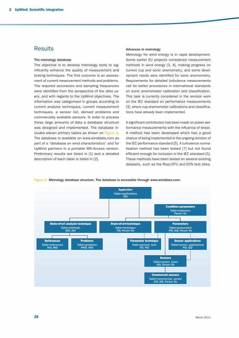
March 201128
Results
The metrology database
The objective is to develop metrology tools to sig-
nifi cantly enhance the quality of measurement and
testing techniques. The fi rst outcome is an assess-
ment of current measurement methods and problems.
The required accuracies and sampling frequencies
were identifi ed from the perspective of the data us-
ers, and with regards to the UpWind objectives. The
information was categorised in groups according to
current analysis techniques, current measurement
techniques, a sensor list, derived problems and
commercially available sensors. In order to process
these large amounts of data a database structure
was designed and implemented. The database in-
cludes eleven primary tables as shown on Figure 2.
The database is available on www. winddata.com as
part of a “database on wind characteristics” and for
UpWind partners in a portable MS-Access version.
Preliminary results are listed in [1] and a detailed
description of each table is listed in [2].
Advances in metrology
Metrology for wind energy is in rapid development.
Some earlier EU projects considered measurement
methods in wind energy [3, 4], making progress on
current cup and sonic anemometry, and some devel-
opment needs were identifi ed for sonic anemometry.
Requirements for detailed turbulence measurements
call for better procedures in international standards
on sonic anemometer calibration and classifi cation.
This task is currently considered in the revision work
on the IEC standard on performance measurements
[3], where cup anemometer calibrations and classifi ca-
tions have already been implemented.
A signifi cant contribution has been made on power per-
formance measurements with the infl uence of shear.
A method has been developed which has a good
chance of being implemented in the ongoing revision of
the IEC performance standard [5]. A turbulence norma-
lisation method has been tested [7] but not found
effi cient enough for inclusion in the IEC standard [5].
These methods have been tested on several existing
datasets, such as the Riso/DTU and ECN test sites.
Figure 2 : Metrology database structure. The database is accessible through www.winddata.com.
Application
Table=applicationsAID
State-of-art analysis techniqueTable=methods
MID, AID
State-of-art-techniqueTable=techniqueTID, Param No
Condition parametersTable=indication
Param No
ReferencesTable=references
RID, MID
ProblemsTable=problems
PRID, MID
SensorsTable=sensor_types
SID, Param No
Commercial sensorsTable=commercial_sensor
CID, SID, Param No
ParametersTable=parametersPID, AID, Param No
Parameter techniqueTable=params_tech
TID, PID
Sensor applicationsTable=sensor_applications
PID, SID
2 UpWind: Scientifi c integration
v3_21895_UpWind Report_AttentionGraphDisparaissent.indd 28v3_21895_UpWind Report_AttentionGraphDisparaissent.indd 28 2/03/11 15:162/03/11 15:16

29 Design limits and solutions for very large wind turbines
In relation to the coming IEC standard on performance
verifi cation with the use of nacelle anemometry [8],
nacelle anemometry has been studied, both the
theory and its practical application [9]. An alternative
to nacelle anemometry has also been developed, the
so-called spinner anemometer [10, 11]. This type of
sensor seems to avoid the draw-backs of nacelle an-
emometry because the sensors are positioned in front
of the rotor on the spinner. Finally, mast correction
measurement has also been developed to improve
current measurements [12].
With respect to new wind measurement technologies
such as remote sensing (LIDAR & SODAR), a substan-
tial number of projects have been undertaken over the
last fi ve years. Ground based LIDARS have been devel-
oped signifi cantly, and in the past few years calibration
and traceability issues have also been tackled and are
now being included in the IEC standard revision [5].
An overview is provided by [6], where signifi cant metrol-
ogy contributions are described.
Focus on LIDAR technology
LIDAR technology is relatively recent and requires
testing. Testing against a traditional meteorological
mast has been shown to be effi cient for gaining
confi dence and trust in measurement accuracy.
In principle, LIDAR measurements could be made
traceable through the fundamental measurement
principles, but at this stage of development it is not
feasible. Instead, traceability is secured through
comparison with meteorological masts that are
themselves traceable through wind tunnel calibrations
of cup anemometers. LIDARs can fulfi l different
objectives:
For resource assessment, and replacing the tradi-
tional measurement masts, UpWind demonstrated
that the ground-based LIDAR measurement principle
is effi cient in fl at terrain. In complex terrain and
close to woods, the measurement volume is dis-
turbed by a vertical turbulence component. Due to a
large measurement volume, ground-based LIDARs
perform a spatial averaging which has the effect of a
low pass fi lter on turbulence measurements. This
effect requires special attention and correction
methods, which were analysed within the UpWind
project by the use of the WAsP engineering tool,
which is a computer based program for the estima-
tion of extreme wind speeds, wind shears, wind pro-
fi les and turbulences in complex (and simple) terrain.
LIDAR measurements were made from a rotating
spinner. The analysis show good perspectives for
scanning the incoming wind, which may lead to bet-
ter controlled wind turbines.
LIDARs have also been used to scan the wake of
wind turbines. These measurements show the
curvy wake pattern. Progress has been made with
large-scale site wind scanning with three coordi-
nated LIDARs.
Verifi cation of anemometer calibrations
In the context of MEASNET 9 a cup anemometer cali-
bration round robin and acoustic noise measurement
round robin were performed [13] with good results for
the associated MEASNET institutes. Together with
the MEASNET experts, UpWind worked to try and
fi nd a procedure for calibrating sonic anemometers.
The operational characteristics of 26 sonic anemom-
eters have been investigated over a long period of time
by [17]. Improvements were required in order to use the
sensors for wind energy applications. These improve-
ments are being implemented by the manufacturer.
9 Measnet: International network for harmonised and recognised measurements in wind energy.
http://www.measnet.com, MEASNET Round Robin (RR) on anemometer calibration is one method of measurement.
v3_21895_UpWind Report_AttentionGraphDisparaissent.indd 29v3_21895_UpWind Report_AttentionGraphDisparaissent.indd 29 2/03/11 15:162/03/11 15:16
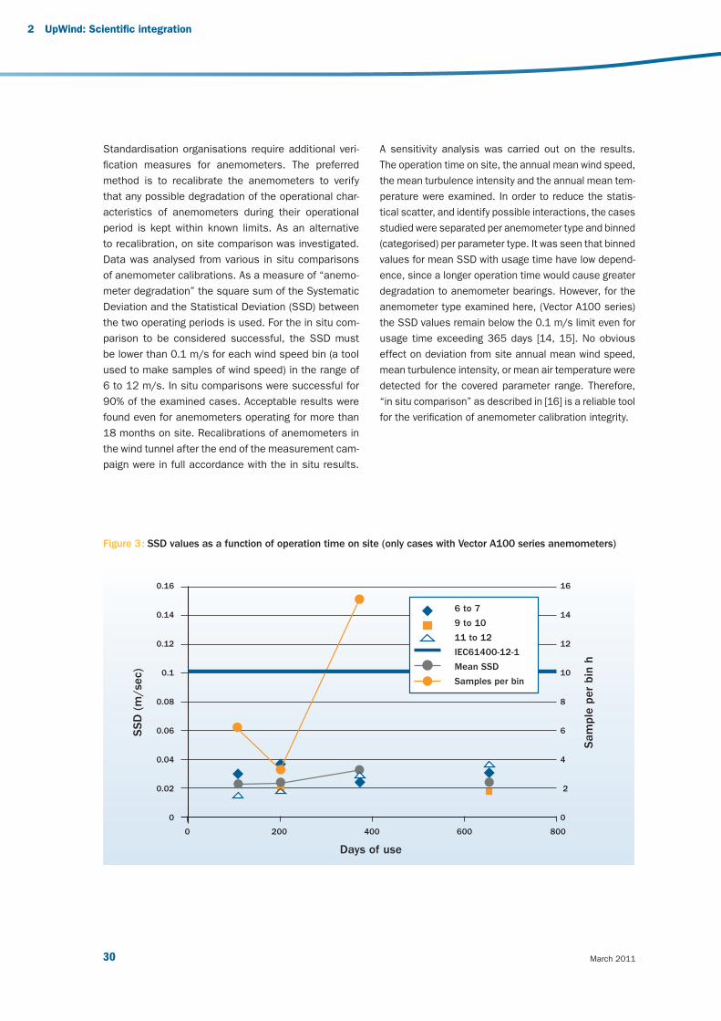
March 201130
Standardisation organisations require additional veri-
fi cation measures for anemometers. The preferred
method is to recalibrate the anemometers to verify
that any possible degradation of the operational char-
acteristics of anemometers during their operational
period is kept within known limits. As an alternative
to recalibration, on site comparison was investigated.
Data was analysed from various in situ comparisons
of anemometer calibrations. As a measure of “anemo-
meter degradation” the square sum of the Systematic
Deviation and the Statistical Deviation (SSD) between
the two operating periods is used. For the in situ com-
parison to be considered successful, the SSD must
be lower than 0.1 m/s for each wind speed bin (a tool
used to make samples of wind speed) in the range of
6 to 12 m/s. In situ comparisons were successful for
90% of the examined cases. Acceptable results were
found even for anemometers operating for more than
18 months on site. Recalibrations of anemometers in
the wind tunnel after the end of the measurement cam-
paign were in full accordance with the in situ results.
A sensitivity analysis was carried out on the results.
The operation time on site, the annual mean wind speed,
the mean turbulence intensity and the annual mean tem-
perature were examined. In order to reduce the statis-
tical scatter, and identify possible interactions, the cases
studied were separated per anemometer type and binned
(categorised) per parameter type. It was seen that binned
values for mean SSD with usage time have low depend-
ence, since a longer operation time would cause greater
degradation to anemometer bearings. However, for the
anemometer type examined here, (Vector A100 series)
the SSD values remain below the 0.1 m/s limit even for
usage time exceeding 365 days [14, 15]. No obvious
effect on deviation from site annual mean wind speed,
mean turbulence intensity, or mean air temperature were
detected for the covered parameter range. Therefore,
“in situ comparison” as described in [16] is a reliable tool
for the verifi cation of anemometer calibration integrity.
Figure 3 : SSD values as a function of operation time on site (only cases with Vector A100 series anemometers)
SS
D (
m/se
c)
Sam
ple
per
bin
h0.16
0.14
0.12
0.1
0.08
0.06
0.04
0.02
0
16
14
12
10
8
6
4
2
0
0 200 400 600 800
Days of use
6 to 7
9 to 10
11 to 12
IEC61400-12-1
Mean SSD
Samples per bin
2 UpWind: Scientifi c integration
v3_21895_UpWind Report_AttentionGraphDisparaissent.indd 30v3_21895_UpWind Report_AttentionGraphDisparaissent.indd 30 2/03/11 15:162/03/11 15:16
31 Design limits and solutions for very large wind turbines
References
[1] Dahlberg J.A., et.al., “Classcup – Development of
a standardized cup anemometer suited to wind
energy applications”, JOULE 2001.
[2] Diznabi B., Investigation of the fl ow relation
to nacelle anemometry, To be published Master
Thesis, March 2009, MEK-FM-EP-2009-03
(not published).
[3] Eecen P.J., Stefanatos N., Petersen S.M., and
Hansen K.S., UPWIND METROLOGY; Deliverable
D 1A2.1 List of Measurement Parameters,
ECN-E--07-015.
[4] Eecen P.J., Stefanatos N., Pedersen T.F. and
Hansen K.S., UPWIND METROLOGY; Deliverable
D 1A2.2 Metrology Database, ECN-E--08-079.
[5] Eecen P.J., and Wagenaar W.J., MEASNET
Anemometer Calibration Round Robin 2009,
Analysis of MEASNET reference wind speed,
ECN-X-10-067.
[6] Eecen P.J., 6th MEASNET Round Robin; Sound
Power Level and Tonality, ECN-X--07-146.
[7] Frandsen S., Sørensen J.N., Mikkelsen R.,
Pedersen T.F., Antoniou I., Hansen K.,
The generics of wind turbine nacelle
anemometry, EWEC 2009.
[8] Lindelöw-Marsden P., Pedersen T.F., Gottschall
J., Vesth A., Wagner R., Paulsen U., Courtney
M.S., Flow distortion on boom mounted cup
anemometers, Risø-R-1738(EN), 2010.
[9] T.F. Pedersen, N.N. Sørensen, P. Enevoldsen
Aerodynamics and characteristics of a spinner
anemometer, The Science of Making Torque from
Wind, August 2007, DTU.
[10] T.F. Pedersen, L. Vita, N.N. Sørensen,
P. Enevoldsen, Operational experiences with a
spinner anemometer on a MW size wind turbine,
EWEC 2008.
[11] Pedersen T.F., Wagner R., et al, Risø-R-1752,
“UPWIND Metrology 1A2.3 – Advancements in
Wind Energy Measurement Methods”, 2010.
[12] N. Stefanatos, P. Papadopoulos, E. Binopoulos,
A. Kostakos, G. Spyridakis, "Effects of long term
operation on the performance characteristics of
cup anemometers” Proc. Of EWEC 2007, Milan.
[13] N. Stefanatos, A. Kostakos, P. Papadopoulos,
E. Binopoulos, "Verifi cation of anemometer
calibrations” Proc. Of EWEC 2010, Warsaw.
[14] J.W. Wagenaar, P.J. Eecen, Gill Windmaster Sonic
Anemometers, ECN-X--09-144.
[15] J.W. Wagenaar, P.J. Eecen, Measurements of Wind,
Wave and Currents at the Offshore Wind Farm
Egmond aan Zee, ECN-E--09-015.
[16] J.W. Wagenaar, P.J. Eecen, 3D Turbulence at
the Offshore Wind Farm Egmond aan Zee,
ECN-E--10-075.
[17] “Accuwind – Accurate wind speed measurements
in wind energy”, Risø-R-1563(EN), JOULE 2006.
[18] IEC61400-12-1, 2005, “Wind Turbines-Part 12-1:
Power performance. measurements of electricity
producing wind turbines”.
[19] IEC61400-12-2-CD “Wind Turbines-Part 12-2:
Power performance. measurements of electricity
producing wind turbines with the use of nacelle
anemometry”.
[20] MEASNET Measurement Procedure:
Cup Anemometer Calibration, Ver. 2 2009.
v3_21895_UpWind Report_AttentionGraphDisparaissent.indd 31v3_21895_UpWind Report_AttentionGraphDisparaissent.indd 31 2/03/11 15:162/03/11 15:16
March 201132
2.3 Work Package 1A3:
Training and education
Challenges and main
innovations
Over the last ten years, installed wind power capacity
has gone up by more than 20% per year. Forecasts
from the industry demonstrate the high potential of
this technology, which will face a critical shortage of
manpower in the coming years. Training and educa-
tion is fundamental element to sustainable industrial
growth.
Working with wind energy technology requires a high
level of education, since improving and enlarging wind
turbines means dealing with specifi c aeromechanical
and structural effects, electrical grid connection and
power quality issues, load regulation and part-load
performance, as well as their potential environmen-
tal impact (noise, visual obstruction, bird migration,
and so on). In the meantime, a signifi cant amount of
research and development work has been and is being
done in the fi eld of wind energy technology, and on-
the-job training is required to update knowledge and
skills. The present situation concerning training and
educational materials is however not ideal. Quite a lot
of material is available, but it is not standardised, it is
diffi cult to access, different courses overlap consider-
ably and so on.
Knowledge dissemination is critical for supporting the
technological innovation of SMEs, which should not
lag behind as wind power technologies develop. A fully
integrated approach, involving academic institutions,
industry and research institutes, is thus necessary
to provide a unique platform to improve educational
materials with respect to content and structure, avoid-
ing overlaps, and being in accordance to the users
specifi cations.
The specifi c objective of the UpWind training and edu-
cation section is to propose a number of modules
for international courses in the wind energy fi eld and
specifi c supporting training materials. These train-
ing modules could then be used (upon request) for
researchers and students (PhD level courses), as well
as for energy consultants and project developers (for
continuous professional development).
“ Wind energy is growing fast, and the technology
improves every day. Training and education
is fundamental to support the wind sector’s
development. UpWind collected and developed a
unique amount of training materials, and defi ned
the required training modules to be used for the
professional development of those that wish to
work in this industry ”
Charalampos Malamatenios, Work Package Leader, Centre for Renewable Energy Sources and Savings (CRES)
2 UpWind: Scientifi c integration
v3_21895_UpWind Report_AttentionGraphDisparaissent.indd 32v3_21895_UpWind Report_AttentionGraphDisparaissent.indd 32 2/03/11 15:162/03/11 15:16

33 Design limits and solutions for very large wind turbines
Results and conclusions
First, preliminary material (in the form of guidelines,
templates and so on) was developed, which helped to
design the UpWind course module for the identifi ed
target groups. Apart from the detailed literature analy-
sis and web-based survey, a questionnaire based sur-
vey was also carried out. Information on wind energy
related training courses was collected from 43 course
providers.
An online database of all courses relevant to wind
energy found all over Europe was developed. This is
the “Database of EU courses in the fi eld of wind energy”,
and it includes all available details (level, contents,
duration, contacts, etc.) for the courses. The database
can be found on UpWind’s website 10.
Another major achievement is the “Wind Energy Informa-
tion and Education Network – WEIEN (e-database)”. This
database is a restricted area within the RenKnow.net 11
website which has been created for the WEIEN mem-
bers with all relevant functionalities of the REnKnow.net
website.
The WEIEN is:
A database for up- and downloading documents;
A forum for discussion;
An “open source knowledge creation” tool (like an
internal “Wikipedia”);
A facilitator of the peer-review process for training
materials.
Work on WEIEN is continuous, as the database has
to be constantly updated. Also, the “resource guide
to course modules” was another important part of
this work, which includes the most essential of the
common components of the courses surveyed, as
well as the key characteristics of the modules that
need to be developed or updated in order to be in-
tegrated into existing and new wind energy courses.
This way, the topics covered by a course that will lead
to a PhD decree were developed. It was decided that
the target groups of the UpWind training course(s)
should already have some basic knowledge of wind
energy technology. Therefore, the aim was not to
create training courses for basic studies, but to build
on the students’ previously acquired knowledge (as
shown in Figure 4).
10 http://www.upwind.eu/Paginas/Publications/1A3%20Training%20and%20Education.aspx11 http://renknownet.iset.uni-kassel.de
Figure 4 : UpWind training targets students of educational levels 2 (i.e. between the basic Levels of 1 and 3)
Habil.,
PhD,
…
Fundamental wind energy training courses
at university level e.g.
wind resources, aerodynamics, Betz,
design, electric machines, grid integration,
economics, etc.
Concentrate ontechnical UpWind issues
Level 1
Level 2
Level 3
UpWindtraining courses
v3_21895_UpWind Report_AttentionGraphDisparaissent.indd 33v3_21895_UpWind Report_AttentionGraphDisparaissent.indd 33 2/03/11 15:162/03/11 15:16

March 201134
The “modules” listed by UpWind are neither full
courses nor simply lectures. Instead, they are building
blocks for university lectures/courses, short courses
for professionals (CPD units), as well as for any other
types of training course. To this end, the content
of the UpWind course modules is not a ready-to-go
lecture package, but rather the material necessary
to set new courses up.
Eleven topics were identifi ed as the key themes
of the UpWind course modules, broken down into
sub-components (according to what is presented in
Table 1). This is a unique attempt to develop up-to-
date courses and relevant training materials for wind
energy:
2 UpWind: Scientifi c integration
1. Aerodynamics and aeroelastics
1.1 Damped structural dynamics for composite rotor blades – tools and exercises
1.2 Advanced aerodynamics and boundary integral element methodology (BEM) corrections
1.3 Aeroelastic stability
2. Rotors Structures and materials
2.1 Innovative materials and processes
2.2 Fundamental and global material models – calculation techniques to evaluate the material damage
2.3 Test/measurement techniques for material and component testing, including procedures
2.4 Elastic stability and static strength of rotor blades – tools and exercises
2.5 Strength and stiffness degradation of rotor blade composites due to fatigue - life prediction
2.6 Structural reliability analysis of composite rotor blades
3. Foundations and support structures
3.1 Introduction to offshore wind technology
3.2 Environmental conditions
3.3 Soil and foundation models
3.4 Support structures I
3.5 Support structures II
3.6 Offshore standardisation
3.7 Integrated design process of explain
3.8 Results of Work Package 4
4. Control systems
4.1 Wind turbine control concepts
4.2 Controller tuning and adjustment
5.3 Control for grid compatibility
5. Condition monitoring
5.1 Optimised Condition Monitoring Systems (CMS) for next generation wind turbines
5.2 “Flight leader turbine” for wind farms
5.3 Fault statistics
5.4 International standards
6. Flow
6.1 Theoretical analysis of wakes
6.2 Analysis of wakes in complex terrain
6.3 Introduction to wake modelling in fl ow simulation
v3_21895_UpWind Report_AttentionGraphDisparaissent.indd 34v3_21895_UpWind Report_AttentionGraphDisparaissent.indd 34 2/03/11 15:162/03/11 15:16

35 Design limits and solutions for very large wind turbines
Table 1 : UpWind training modules.
In the last stages of the project, the various UpWind
training modules were run as pilots:
University status partners used the modules for
postgraduate students and lecturers from other uni-
versities;
Non-university status partners used selected mod-
ules developed in WP1A.3 to run workshops on the
main topics of wind energy technology;
A detailed presentation of the modules created by
this WP was given in a workshop that addressed
PhD candidates with a background in engineering.
7. Electrical grid
7.1 Introduction to wind power grid connection and integration
7.2 Introduction to power system reliability
7.3 Wind turbines and wind farm design and reliability
7.4 Power system security and wind turbine stability
7.5 Power system control with wind power
7.6 Results from UpWind Work Package 9
8. Measurements and experiments in wind energy
8.1 Principles of experiments
8.2 Wind turbine test site
8.4 Wind resource measurements
8.5 Special experiments
9. Transmission and conversion
9.1 Mechanical transmission
9.2 Generators
9.3 Power electronics
10. Integral design approach & standards
10.1 Introduction
10.2 Integral design approach
10.3 Cost models
10.4 Uncertainty modelling
10.5 Reliability methods
10.6 Standards
11. Upscaling and integrated design:
11.1 Classical upscaling
11.2 Upscaling through design
11.3 Cost models I
11.4 Cost models II
11.5 Upscaling issues
11.6 Future concepts
v3_21895_UpWind Report_AttentionGraphDisparaissent.indd 35v3_21895_UpWind Report_AttentionGraphDisparaissent.indd 35 2/03/11 15:162/03/11 15:16

March 201136
Photo
: Vesta
s
UPWIND: TECHNOLOGY INTEGRATION3
v3_21895_UpWind Report_AttentionGraphDisparaissent.indd 36v3_21895_UpWind Report_AttentionGraphDisparaissent.indd 36 2/03/11 15:162/03/11 15:16
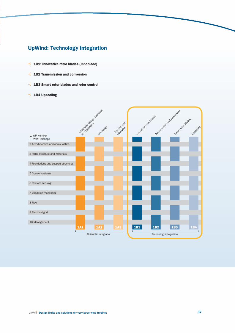
37 Design limits and solutions for very large wind turbines
UpWind: Technology integration
1B1: Innovative rotor blades (Innoblade)
1B2 Transmission and conversion
1B3 Smart rotor blades and rotor control
1B4 Upscaling
WP Number
Work Package
2 Aerodynamics and aero-elastics
3 Rotor structure and materials
4 Foundations and support structures
5 Control systems
6 Remote sensing
7 Condition monitoring
8 Flow
9 Electrical grid
10 Management
1A1 1A3 1B1 1B2 1B3 1B4
Integrated
des
ign ap
proa
ch
and stan
dards
Scientifi c integration Technology integration
Metrology
Inno
vativ
e rotor b
lade
s
Tran
smission
and
con
version
Smar
t rotor blade
s
1A2
Upsc
aling
Training
and
educ
ation
v3_21895_UpWind Report_AttentionGraphDisparaissent.indd 37v3_21895_UpWind Report_AttentionGraphDisparaissent.indd 37 2/03/11 15:162/03/11 15:16
March 201138
3.1 Work Package 1B1:
Innovative rotor blade
(Innoblade)
Challenges and main
innovations
In the last years the cost of wind energy has decreased
due to technical improvements in aerodynamics, ma-
terials and structures, reaching an almost constant
cost per KW recently. In order to move towards more
effi cient wind turbine designs (bigger rotor diameters
with lower energy costs), new innovative improvements
are needed.
Future multi-megawatt machines will require large
blades whose transport costs would become unaf-
fordable for blades longer than 50m. Sectional
blades, meaning blades divided into sections, are
the best way to reduce transport costs while in-
creasing the length of the blades. These blades will
be manufactured in separated modules that will be
assembled on site.
UpWind has focused on the design and validation of a
sectional blade concept which aims to reduce the glob-
al cost of energy and to help develop larger turbines.
This blade concept includes several new technological
advances regarding blade design and manufacturing,
such as advanced aerodynamic profi les, advanced
design solutions, analysis of new materials, and
advanced sensor and monitoring technologies, among
others.
Results
Blade aerodynamic design and load calculation
This analysis included aerodynamics design, aero-
elastic design and loads consideration, making use
of all current methodologies, but also employing
innovative methods that are beyond current practice,
such as:
Profi le design for effi cient energy production as a
design option, in relation to the Sirocco project in
which both Gamesa Innovation and Technology and
ECN are involved. For an optimal design and per-
formance, materials and structural design improve-
ments were considered.
Contribution of aero-elastic analysis, with the re-
sults from FP5 projects Dampblade and Stabcon.
Aerodynamics design taking into account blade
deformation.
The use of the blade joints and their effect on
modal shapes.
Integration of the control system in the aerody-
namic design and loads calculation, considering
blade monitoring and load mitigation strategies.
Optimisation criteria and design optimisation
procedures.
“ One key point when thinking about increasing the size of wind
turbine blades is transport costs. In order to keep these costs under
acceptable limits the best choice is sectional blades, capable of being
transported with the same means as smaller blades. The use of new
tools for the better understanding of such huge blades as well as a
reliable monitoring system of the blade are key factors to this new
generation of blades ”
Joaquin Arteaga Gomez, Work Package Leader, Gamesa
3 UpWind: Technology integration
v3_21895_UpWind Report_AttentionGraphDisparaissent.indd 38v3_21895_UpWind Report_AttentionGraphDisparaissent.indd 38 2/03/11 15:162/03/11 15:16

39 Design limits and solutions for very large wind turbines
These methods were applied to the design of a 42.5 m
blade (this size was chosen to test these new technolo-
gies, using a Gamesa design as starting point) leading to
a functional design of a sectional blade with the following
characteristics and conclusions:
Brand new “fl at–back” profi les were developed for
the sections close to the base of the blade (of
special relevance for larger blades)
The use of a root fairing was analysed, with the
conclusion that it would lead to a small increase
in the power produced
The effects on the modal shapes and natural
frequencies of the sectional joint position were
studied, with the conclusion that no relevant dif-
ferences appear when it is placed between R 10
to R20 (measure of resistance).
A study of blade damping checked the stability of the
blade at different confi gurations (for example, the effect
of wind with an angle of attack of around 90º on inac-
tive wind turbines). These results were presented at the
EWEA Annual Event (formerly EWEC) 2009.
Material selection, structural design and structural
verifi cation
The current state of composite materials was analysed
as well as any new potential materials or innovations
that could contribute to better blade designs, and spe-
cifi cally to the design of sectional blades. This analysis
found that even though there were promising research
areas in the fi eld, no breakthroughs were about to be
achieved, so today a large blade (sectional or otherwise)
is built using the standard materials and processes
(glass fi bre and carbon fi bre, as prepregs or dry plies
for infusion).
After this, the structural design of the proposed blade
was examined, fi rst considering the blade as a single
component and secondly as a sectional blade using the
one piece confi guration as a starting point. This also
included the selection of the position of the sectional
joint, choosing the R15 after considering all the factors
(effects on modal shapes and frequencies, weight and
length of the two modules and so on).
Sensor monitoring with response actions
The possibility to monitor the behaviour of the sec-
tional joint of the innovative blade at any given time
(for analysis, validation and maintenance) is important.
A series of sensors is required, and the measured data
needs to be transferred to a processing unit. The use
of cable for this transferring is complicated and risky.
As an alternative, a wireless sensor system was con-
sidered by UpWind. After the current technology had
been reviewed and the different solutions analysed,
a system was designed based on the Zigbee certifi -
cation standard. From the test carried out using this
system it was found that:
Signal reception was good up to 30-40 m with a
sensor-emitter placed inside the blade and a receiver
at the nacelle, showing no differences between car-
bon or glass fi bre blades.
Wireless sensors shouldn’t be placed too close to
metallic components of the blade.
The results were satisfactory (good signal reception)
even with the machine rotating.
Power consumption was acceptable, and will depend
on the amount of data to be transmitted.
outboardblade
inboardblade
Figure 5 : Sectional blade
v3_21895_UpWind Report_AttentionGraphDisparaissent.indd 39v3_21895_UpWind Report_AttentionGraphDisparaissent.indd 39 2/03/11 15:162/03/11 15:16
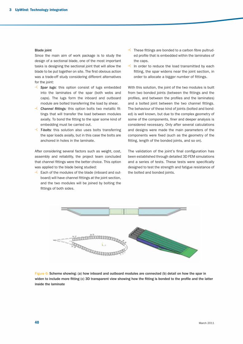
March 201140
3 UpWind: Technology integration
Blade joint
Since the main aim of work package is to study the
design of a sectional blade, one of the most important
tasks is designing the sectional joint that will allow the
blade to be put together on site. The fi rst obvious action
was a trade-off study considering different alternatives
for the joint:
Spar lugs: this option consist of lugs embedded
into the laminates of the spar (both webs and
caps). The lugs form the inboard and outboard
module are bolted transferring the load by shear.
Channel fi ttings: this option bolts two metallic fi t-
tings that will transfer the load between modules
axially. To bond the fi tting to the spar some kind of
embedding must be carried out.
T-bolts: this solution also uses bolts transferring
the spar loads axially, but in this case the bolts are
anchored in holes in the laminate.
After considering several factors such as weight, cost,
assembly and reliability, the project team concluded
that channel fi ttings were the better choice. This option
was applied to the blade being studied:
Each of the modules of the blade (inboard and out-
board) will have channel fi ttings at the joint section,
and the two modules will be joined by bolting the
fi ttings of both sides.
These fi ttings are bonded to a carbon fi bre pultrud-
ed profi le that is embedded within the laminates of
the caps.
In order to reduce the load transmitted by each
fi tting, the spar widens near the joint section, in
order to allocate a bigger number of fi ttings.
With this solution, the joint of the two modules is built
from two bonded joints (between the fi ttings and the
profi les, and between the profi les and the laminates)
and a bolted joint between the two channel fi ttings.
The behaviour of these kind of joints (bolted and bond-
ed) is well known, but due to the complex geometry of
some of the components, fi ner and deeper analysis is
considered necessary. Only after several calculations
and designs were made the main parameters of the
components were fi xed (such as the geometry of the
fi tting, length of the bonded joints, and so on).
The validation of the joint’s fi nal confi guration has
been established through detailed 3D FEM simulations
and a series of tests. These tests were specifi cally
designed to test the strength and fatigue resistance of
the bolted and bonded joints.
Figure 6: Scheme showing: (a) how inboard and outboard modules are connected (b) detail on how the spar in
widen to include more fi tting (c) 3D transparent view showing how the fi tting is bonded to the profi le and the latter
inside the laminate
v3_21895_UpWind Report_AttentionGraphDisparaissent.indd 40v3_21895_UpWind Report_AttentionGraphDisparaissent.indd 40 2/03/11 15:162/03/11 15:16

41 Design limits and solutions for very large wind turbines
References
[1] Ashwill T.D. and Paquette J.A., “Composite
Materials For Innovative Wind Turbine Blades”,
Wind Energy Technology Department, Sandia
National Laboratories, Albuquerque, NM.
[2] Brøndsted P., Lilholt H., and Lystrup A.,
“Composite Materials For Wind Power Turbine
Blades”, Materials Research Department, Risoe
National Laboratory, Denmark, April 2005 “MIL-
HDBK-17-3F”, Department of Defense, US, June
2002.
[3] Bruhn E.F.. Analysis and Design of Flight Vehicle
Structures. Jacobs publishing, Inc. Indianapolis.
1973.
[4] Burton T., Sharpe D., Jenkins N. Y, Bossanyi E.
Wind Energy Handbook. Wiley. 2001.
[5] Chaviaropoulos, P.K., “Flap/Lead–lag Aero-elastic
Stability of Wind Turbine Blades,” Wind Energy,
2001, 4, 183–200.
[6] Chaviaropoulos, P., Politis, E.S., Lekou, D.J.,
Sorensen, N. N, Hansen, M., Bulder, B. H.,
Winkelaar, D., Lindenburg, C., Saravanos, D.A.,
Philippidis, T.P., Galiotis, C., Hansen, M.O.L.,
Kossivas, T., “Enhancing the Damping of Wind
Turbine Rotor Blades, the DAMPBLADE Project,”
Wind Energy, 2006, 9, 163–177.
[7] Doyle C. (Smart Fibres). Fibre Bragg Grating
Sensors, An introduction to Bragg gratings and
interrogation techniques, 2003.
[8] Dutton A.G. (ERU), Blanch M.J. (ERU), Vionis
P. (CRES), Lekou D. (CRES), van Delft D.R.V.
(Delft University), Joosse P.A. (Delft University),
Anastassopoulos (Envirocoustics Abee), Kossivas
T. (Geobiologiki S.A.), Philippidis T.P. (University
of Patras), Kolaxis Y.G. (University of Patras),
Fernando G. (Cranfi eld University), Proust A.
(Euro Physical Acoustics, S.A.), Acoustic Emission
Monitoring during Certifi cation Testing of Wind
Turbine Blades. (AEGIS Project), February 2003.
[9] Fragoulis, A., MOUNTURB: Load and Power
Measurement Program on Wind Turbines
Operating in Complex Mountainous Regions,
Final Report for JOU2-CT93-0378 CEU project,
1996.
[10] Fragoulis, A., COMTER.ID: Investigation of
Design Aspects and Design Options for Wind
Turbines.
[11] Operating in Complex Terrain Environments,
Final Report for JOR3-CT95-0033 CEU project,
1998.
[12] Frazao O. (INESC), Romero R. (INESC), Santos
J.L. (INESC, Universidade do Porto). Simultaneous
Measurement of Temperature and Strain using
Ring Fiber Bragg Grating Sensors. OFS 16 2003.
[13] García R. (Univ. Politécnica de Valencia), Sales
S. (Univ. Politécnica de Valencia), Capmany
J. (Univ. Politécnica de Valencia), Warzanskyj
W. (Telefónica I+D), McDonald D. (Intune
Technologies), Bastiani M. (Ecoazioni). A new
interrogation system for a large number of strain
sensors using Fiber Bragg Grating for application
in residential buildings. II European Workshop
on OFS 2004.
[14] Gdoutos E.E.; Daniel I.M.; Wang K.-A.
Compression facing wrinkling of composite
sandwich structures. ELSEVIER. January, 2002.
[15] Griffi n, D.A., “Blade System Design Studies
Volume I: Composite Technologies for Large
Wind Turbine Blades”,. SAND2002-1879, Sandia
National Laboratories, Albuquerque, NM.
[16] Griffi n, D.A., “Blade System Design Studies
Volume II: Preliminary Blade Designs and
Recommended Test Matrix”, SAND2004-0073,
Sandia National Laboratories, Albuquerque, NM.
[17] Jones R. M. Mechanics of Composite Materials.
Scripta Book Co. Washington D.C. 1975.
v3_21895_UpWind Report_AttentionGraphDisparaissent.indd 41v3_21895_UpWind Report_AttentionGraphDisparaissent.indd 41 2/03/11 15:162/03/11 15:16
March 201142
3 UpWind: Technology integration
[18] Kristensen O.J.D., McGugan M., Sendrup P.,
Rheinlander J., Rusborg J., Hansen A.M.,
Debel C.P., Sorensen B.F., Fundamentals for
Remote Structural Health Monitoring of Wind
Turbine Blades Annex E – Full-Scale Test of Wind
Turbine Blade, Using Sensors NDT, RISO-R-
1333(EN), May 2002.
[19] Lading L., McGugan M., Sendrup P., Rheinlander
J., Rusborg J., Fundamentals for Remote
Structural Health Monitoring of Wind Turbine
Blades Annex B – Sensors and Non-Destructive
Testing Methods for Damage Detection in Wind
Turbine Blade s, RISO-R-1341(EN), May 2002.
[20] Lystrup A., ‘Vacuum consolidation of
thermoplastic composites for wind turbine rotor
blades’, Proceedings of the 27th RisøInternational
Symposium on Materials Science, September
2006, p231-238.
[21] Mandell J.F, Samborsky D.D., Li M. Orozco
R., and Cairns D.S., “Selection Of Fiberglass
Matrix Resins For Increased Toughness And
Environmental Resistance In Wind Turbine
Blades”, Department of Chemical Engineering
and Department of Mechanical Engineering,
Montana State University, Bozeman, MT.
[22] Markou H., Hansen M.H., Buhl T., van Engelen
T., Politis E.S., Riziotis V.A., Poulsen,N.K., Larsen,
A.J., Mogensen, T.S., Holierhoek, J.G., “Aeroelastic
Stability and Control of Large Wind Turbines –
Main Results,” Proceedings of the 2007 European
Wind Energy Conference & Exhibition, Milan.
[23] Niu M.C.Y., Airframe Structural Design. Technical
Book Company, 1988.
[24] Niu M. Composite airframe structures. Hong
Kong Conmilit press LTD. Hong Kong. January
1992, Third edition June 2000.
[25] Parton H. ‘Characterisation of the in-situ
polymerisation production process for
continuous fi bre reinforced thermoplastics’, PhD
Thesis, KU Leuven, February 2006.
[26] Riziotis V.A., Voutsinas S.G., “GAST: A General
Aerodynamic and Structural Prediction tool
for Wind Turbines,” Proceedings of the 1997
European Wind Energy Conference & Exhibition,
Dublin, Ireland.
[27] Riziotis V.A., Voutsinas S.G., Politis E.S.,
Chaviaropoulos P.K., “Assessment of Passive
Instability Suppression Means on Pitch-regulated
Wind Turbines,” Wind Energy, 1008, 11, 171-192.
[28] Riziotis V.A., Voutsinas S.G. “Dynamic stall on
wind turbine rotors: comparative evaluation
study of different models,” Proceedings of the
1997 European Wind Energy Conference &
Exhibition, Dublin, Ireland.
[29] Riziotis V.A., Voutsinas S.G., Politis E.S.,
Chaviaropoulos P.K., “Aeroelastic Stability of
Wind Turbines: The Problem, the Methods and
the Issues,” Wind Energy, 2004, 7, 373–392.
[30] Schepers J.G., Snel, H., Joint Investigation of
Dynamic Infl ow Effects and Implementation of
an Engineering Method for Response Analysis,
ECN Report ECN-C-94-107, the Netherlands, 1994.
[31] Schepers J.G., Snel, H., Dynamic Infl ow: Yawed
Conditions and Partial Span Pitch Control, ECN
Report ECN-C-95-056, The Netherlands, Final
Report for JOU2-CT92-0186 CEU project, 1995.
[32] Schepers J.G., VEWTDC: Verifi cation of European
Wind Turbine Design Codes, Final Report for
JOR3-CT98-0267 Joule III project, ECN, 2001.
v3_21895_UpWind Report_AttentionGraphDisparaissent.indd 42v3_21895_UpWind Report_AttentionGraphDisparaissent.indd 42 2/03/11 15:162/03/11 15:16

43 Design limits and solutions for very large wind turbines
[33] Schlotter M., “A Comparison of Core Materials for
Sandwich Composite Constructions”. June, 2002.
[34] Sundaresan M.J. (NREL), Shulz M.J. (NREL),
Ghoshal A. (NREL), Structural Health Monitoring
Static Test of a Wind Turbine Blade, August 1999.
[35] Teuwen J., ‘Vacuum infused thermoplastic
composites for wind turbine blades’, Presentation
at Wind Turbine Blade Workshop, Sandia
National Laboratories, 12-14 May 2008.
[36] Tsai S.W.; Hahn, H. T. Introduction to Composite
Materials. Technomic Publishing Company.
Wesport.1980.
[37] Van Rijswijk K., Bersee H.E.N., ‘Reactive
processing of textile fi ber-reinforced
thermoplastics – An overview’, Composites:
Part A, 2006.
[38] Van Rijswijk K., Bersee H.E.N., Beukers A.,
Picken S.J., Van Geenen A.A., ‘Optimisation
of anionic polyamide-6 for vacuum infusion
of thermoplastic composites: Infl uence of
polymerization temperature on matrix properties’,
Polymer Testing, volume 25, 2006, p392-404.
[39] Van Rijswijk K., Bersee H.E.N., Beukers A.,
Picken S.J., Van Geenen A.A., ‘Optimisation of
anionic polyamide-6 for vacuum infusion of
thermoplastic composites: Choice of activator and
initiator’, Composites: Part A, volume 37, 2006,
p949-956.
[40] Verghese K.E., “Durability of Polymer Matrix
Composites for Infrastructure: The Role of the
Interphase”, in Materials Engineering Science.
1999, Virginia Polytechnic Institute and State
University: Blacksburg, VA.
[41] Zingraff L. et al., ‘Resin transfer moulding
of anionically polymerised polyamide 12’,
Composites Part A, Vol. 36, Issue 12,
December 2005, pages 1675-1686.
[42] DS 472. Code of practice for loads and safety of
wind turbine constructions. The Danish Society
of Engineers and the Federation of Engineers.
1992.
[43] Gamesa Structures Manual (FSM).
[44] Germanischer Lloyd – Rules and Regulations.
Non Marine Technology. Regulations for the
Certifi cation of Wind Energy Conversions
Systems. 2003.
[45] IEC 61400-1 Ed.3: Wind Turbine Generator
Systems – Part 1: Safety Requirements.
International Electrotechnical Commission.
Mayo, 2005.
[46] IEC 61400-1 Ed.3: Wind turbines - Part 1:
Design requirements. International
Electrotechnical Commission. Mayo, 2005.
[47] IV-1 Guideline Certifi cation Wind Turbines.
Ed. 2003, sup. 2004. Germanischer Lloyd Wind
Energie. 2004.
[48] TPI Composites, Inc. “Innovative Design
Approaches for Large Wind Turbine Blades Final
Report: WindPACT Blade System Design Studies”
Sandia National Laboratories: Albuquerque, NM.
SAND 2004-0074, Mayo 2004.
v3_21895_UpWind Report_AttentionGraphDisparaissent.indd 43v3_21895_UpWind Report_AttentionGraphDisparaissent.indd 43 2/03/11 15:162/03/11 15:16

March 201144
3 UpWind: Technology integration
3.2 Work Package 1B2:
Transmission and conversion
Challenges and main
innovations
The aim for both current wind turbine sizes and for
future larger-scale designs is to increase reliability,
predictability and effi ciency. In terms of reliability, the
drive train today is still among the most critical com-
ponents. It is assumed that the underlying problem of
unexpected failures is based on a misunderstanding
of the dynamic behaviour of the complete wind turbine
system due to the lack of a ready-to-use integral de-
sign approach. UpWind developed and validated the
necessary simulation tools to overcome this problem.
Concentrating on upscaled designs, the weight on top
of the mast is critical for transport, installation and
design loading. The perfect generator would be reli-
able, effi cient and light. UpWind investigated the path-
ways towards effi cient large-scale generators, compar-
ing the existing generator types on energy yields and
through cost models. Particular attention was paid
to permanent magnet generators, currently entering
the market with competitive designs, and potentially
opening the door to increased reliability and effi ciency.
Little room is available for the optimisation of radial fl ux
permanent magnet generators, although their shape is
a compromise between diameter and weight. On the
contrary, transversal fl ux permanent magnet genera-
tors could be promising. An analysis was performed to
compare the mass of ten different generator confi gura-
tions. It seems the transversal fl ux generators could
be signifi cantly lighter, thus avoiding a linear increase
of the top of mast weight ratio for increasingly large
turbines, and opening new possibilities for upscaling.
Different voltage levels were studied and assessed,
potentially further decreasing the costs.
Results
Mechanical transmission
In terms of reliability, the drive train is still among the
most critical components of modern wind turbines.
Nowadays the typical design of the drive train consists
of an integrated serial approach where the single com-
ponents, such as the rotor shaft, main bearing, gearbox
and generator are as close together as possible to
ensure compactness and as low a mass as possible.
Experience from across the wind industry shows that
this construction approach results in many types of fail-
ures (especially gearbox failures) of drive train compo-
nents, although the components are designed accord-
ing to contemporary design methods and known loads.
It is assumed that the underlying problem of all these
“ Size and weight do matter. We had to investigate the limits of current
designs. UpWind provided the necessary tools for upscaling. Integral
design tools will signifi cantly increase the reliability of future drive
trains, and avoid costly drive train failures. UpWind specifi ed the
future generator type, which is proportionally lighter than today’s
designs.”
Jan Hemmelmann, Work Package Leader, GE Global Research
v3_21895_UpWind Report_AttentionGraphDisparaissent.indd 44v3_21895_UpWind Report_AttentionGraphDisparaissent.indd 44 2/03/11 15:162/03/11 15:16

45 Design limits and solutions for very large wind turbines
unexpected failures is based on a basic misunderstand-
ing of the dynamic behaviour of the complete wind
turbine system due to the lack of a ready-to-use integral
design approach. The construction approach should
simultaneously integrate the structural nonlinear elastic
behaviour with the coupled dynamic behaviour of multi
body systems together with the properties of electrical
components. The following different system parts need
to be addressed within one coupled “integral” model:
Wind fi eld simulation;
Aero-elastic interaction at blades;
Non-linear fl exibilities of fi bre blades;
Linear fl exibilities of metal components e.g. of
drive train;
Non-linear behaviour of drive train components e.g.
gears, bearings, bushings;
Electro-mechanic behaviour of generator;
Electrical behaviour of power electronic converter
and grid.
To overcome the limitations identifi ed in design and
reliability, it was necessary to develop and verify new
and enhanced simulation tools. A Multi Flexible Body
Dynamics (MFBD) simulation tool based on the pre-
existing non-linear Finite Element Analysis (FEA) code
SAMCEF Mecano was used, adapted and verifi ed for
detailed analyses of drive train behaviour. A customised
Open Computer Aided Engineering software platform
based on plug-in techniques for a wind turbine applica-
tion has been developed. It contains the pre-defi ned
or user defi ned models developed and validated during
the project, with a focus on the drive train. Figure 7
shows the graphical user interface of this profes-
sional software environment that can also be used
for various kinds of analyses and post-processing.
It can also be extended towards specialised computa-
tion software to cover the whole design process from
the concept to a detailed analysis of the components.
The tool and the model had to be validated through
a comparison with the results of the experiments.
Measurements have been taken on a 1.5 MW turbine
and compared to the simulation results, with empha-
sis on drive train behaviour. It could be shown that
specifi c behaviour of drive train components can be
simulated, matching the observations.
Further enhancements to the multi-body simulation
tools were studied with regard to gear mesh behav-
iour. Usually the gear stiffness (for MFBD) is defi ned
as a constant value or an analytic function changing
with time, but for a detailed gearbox analysis these
assumptions are too simplistic. It was proposed that
realistic time varying stiffness gained via FE-simulation
could be used. The mesh stiffness can be computed
using gear tooth contact analysis software, consid-
ering modifi cations of the teeth like e.g. crownings,
and also considering different torque levels. Thus the
mesh stiffness can be varied depending on the torque,
the rolling position of the gears and the gear defl ection
in a static mode, and used for the dynamic simulation.
Figure 7: The challenge of this task was the coupling
with the MBS model of the wind turbine.
v3_21895_UpWind Report_AttentionGraphDisparaissent.indd 45v3_21895_UpWind Report_AttentionGraphDisparaissent.indd 45 2/03/11 15:162/03/11 15:16

March 201146
Generators
The main objective was to fi nd the most suitable genera-
tor system for the large wind turbines expected by 2020.
Currently, there are three main generator systems used
in wind turbines: constant speed with a gearbox and a
squirrel cage induction generator, variable speed with a
gearbox and doubly-fed induction generators, and vari-
able speed direct-drive generators without a gearbox.
Each concept has its disadvantages.
A fi rst task was a thorough comparison of these
and other possible generator concepts based on
cost models and energy yield models. An overview
of wind turbine technologies and a comparison of
different generator topologies based on literature
and market supply review was carried out. Promis-
ing direct-drive permanent magnet (PM) machines,
which include the axial fl ux (AF), radial fl ux (RF) and
transverse fl ux (TF) machines, have been surveyed
in literature and compared based on the technical
data and market aspects. In case of RFPM machines,
it can be concluded that the machines are almost
optimised electromagnetically, so that it is hard to
reduce the active material weight and cost of the
machines signifi cantly. The disadvantages of the
AFPM machine must be solved, because it causes
the machine cost to increase and manufacturing to be
diffi cult. TFPM machines have disadvantages such as
complicated construction and manufacturing, and low
power factor, although the machines have advantages
such as high force density and simple winding with low
copper losses.
The second task was to evaluate the most cost-effec-
tive wind turbine generator systems by applying design
optimisation and numerical comparison. An integrated
electromagnetic-structural optimisation strategy was
developed to provide the best structural design for
direct drive RFPM generators. The preliminary results of
a structural optimisation highlighted the danger of not
optimising the active and inactive material together –
that is, the fact that a generator design that minimises
active mass leads to a design that maximises inactive
or structural mass. Traditionally in the design of the ac-
tive mass, the air gap is kept as small as possible to
optimise the electromagnetic performance. However,
the integrated electromagnetic–structural optimisation
strategy indicated that machines with a larger air gap
will result in lower mass. The aspect ratio of the genera-
tor (ratio of length to air gap radius), depends upon the
optimisation criteria. For minimum mass, large aspect
ratios with a larger air gap is desirable, leading to a
sausage shaped machine. If cost is key, then small as-
pect ratios or pancake machines are more desirable,
because active mass decreases with radius, and this is
the most expensive part of the generator. The optimisa-
tion strategies were also been applied to TFPM machine
topologies.
A third task was to identify the most suitable generator
type for large direct-drive wind turbines based on elec-
tromagnetic analysis models for various confi gurations
of PM machines. The surface mounted RFPM machine
and four different fl ux-concentrating TFPM machines with
single-winding were chosen for the comparative design,
where a single-sided single-winding fl ux-concentrating
TFPM generator was found to be most promising. The
analysis models were verifi ed by experiments and fi nite
element analyses of a down-scaled, linearised generator.
In order to further reduce the active mass of TFPM ma-
chines, a confi guration with multiple-slots is proposed in
order to shorten the length of the fl ux path, which yields
more potential to reduce the active mass than RFPM
generators. Figure 8 illustrates the active mass compari-
son of different 10 MW PM generators, where the RFPM
generator serves as baseline and nine different TFPM
generators are compared to it. The active mass of a claw
pole design with limited pole area and up to four slots
per phase seems to have potential against the baseline
machine. To validate these analytical design results,
three-dimensional fi nite element analyses are needed.
3 UpWind: Technology integration
v3_21895_UpWind Report_AttentionGraphDisparaissent.indd 46v3_21895_UpWind Report_AttentionGraphDisparaissent.indd 46 2/03/11 15:162/03/11 15:16

47 Design limits and solutions for very large wind turbines
Power electronics
While acknowledging that doubly-fed induction genera-
tors are almost standard today, the UpWind research
focused on full converter solutions for synchronous
generators. Three different approaches to increase the
power rating to the required level were analysed in de-
tail. An example of a design approach including power
device selection, selection of switching frequency, fi lter
design, effi ciency curve, volume estimates and control
scheme was drawn up. These concepts include the
matrix converter, the three-level neutral point clamped
(NPC) converter and the parallel interleaved converter.
As a result of the benchmarks it can be noted that all
topologies are potential candidates for next genera-
tion wind turbines and can serve the desired power
conversion rating. The matrix converter is the topology
offering the most potential for future developments.
Currently the lack of tailor-made power semiconduc-
tors is a substantial drawback. The three-level NPC is
a well established converter topology for the desired
output power range, and it supports different out-
put voltage levels. The parallel interleaved converter
topology provides very good harmonic performance at
the grid interface. The improvements on the harmonic
performance are achieved at the expense of some ad-
ditional circulating currents. A fact common to all three
topologies is that the highest conversion effi ciency is
achieved with the use of low voltage semiconductors
(1700V IGBTs). However from the point of view of total
system cost there is a tendency to aim for voltages
that are as high as possible to decrease transformer
and conductor costs.
250
200
150
100
50
0
RFP
M
TFP
M-U
TFP
M-C
P/1/L
TFP
M-C
P/2/L
TFP
M-C
P/4/L
TFP
M-C
P/8/L
TFP
M-C
P/1/A
TFP
M-C
P/2/A
TFP
M-C
P/4/A
TFP
M-C
P/8/A
Generator total active mass
Copper mass
Stator core mass
PM mass
Rotor core mass
Abbreviations
U: U-core shape
CP: claw poles
1..8: number of slots per phase
L: limited axial length
A: limited pole area
Generator type
Acti
ve m
ass [
ton]
Figure 8: Active mass comparison of different 10 MW PM generators.
v3_21895_UpWind Report_AttentionGraphDisparaissent.indd 47v3_21895_UpWind Report_AttentionGraphDisparaissent.indd 47 2/03/11 15:162/03/11 15:16

March 201148
3 UpWind: Technology integration
3.3 Work Package 1B3: Smart rotor
blades and rotor control
Challenges and main
innovations
Increasing the rotor diameters of current turbines
enables more energy to be generated, but without in-
novation in load control, this would also increase the
fatigue loading on the entire structure, and require
costly structure reinforcements. Load control is also
crucial to reduce the structural requirements of the large
turbines of the future, with their large rotor diameters.
Load control can lead to lighter blades or longer blades
with the same weight, increased component lifetime,
and so it can help with upscaling.
Reducing the fatigue loads leads to lower cost energy,
if it can be implemented in a way that does not add
too much complexity to the turbine. Today, the current
control features of wind turbines do provide the control
authority over the loading that is required for fatigue load
reduction. Therefore, UpWind researched the potential
of the alleviation of unwanted loading of wind turbines,
not only of fatigue loads, but also of peak loads as a
result of gusts, with new tools. The challenges that are
encountered in this work are related to:
Sensors and control issues, related to the servo-
aero-elastic behaviour of the turbine;
Actuator technology;
The (unsteady) aerodynamics of aerofoils with
control devices;
The way the control devices are implemented is
important. Control devices infl uence the aerodynam-
ics, while seeking a reduction in a structural res-
ponse. Numerous devices can be implemented in this
regard, such as trailing edge fl aps, (continuous) camber
control, synthetic jets, micro tabs, or fl exible, control-
lable blade root coupling.
Little is known about the aerodynamic performance
of those devices on wind turbines or how they should
be integrated in the blade’s structure. UpWind inves-
tigated different options. First by simulating a rotor
for a 5 MW turbine, and demonstrating 15 to 25%
load reduction, then by investigating adaptive trail-
ing edges using shape memory alloys, or increasing
fl exibility by allowing a degree of freedom between
the hub and the blade to be temporarily uncoupled.
The necessary simulation and control tools were de-
veloped, and wind tunnel experiments of smart rotor
blades were implemented. The fi nal result consists
of a set of tools for further development and for the
industry, ranging from aero-elastic codes to predict
the behaviour of wind turbines with smart features
to dedicated aerofoils and smart actuators.
“ Longer blades mean more energy harnessed, but
higher loads which could hamper an effi cient
design. UpWind successfully simulated and tested
several techniques to control the loads along the
blade span. This is the fi rst step towards a new
rotor technology ”
Gijs van Kuik, Work Package Leader, Energy Research Centre of the Netherlands (ECN)
v3_21895_UpWind Report_AttentionGraphDisparaissent.indd 48v3_21895_UpWind Report_AttentionGraphDisparaissent.indd 48 2/03/11 15:162/03/11 15:16

49 Design limits and solutions for very large wind turbines
Research activities and working
methods
Task 1: Aerodynamic controls and aero-elastic
modeling
An aerofoil with fl ap design was tested and an aerody-
namic analysis carried out on it. Current aerofoils are
not developed for trailing edge fl ap operation. UpWind
investigated the lift and drag characteristics of a typi-
cal, existing tip-aerofoil with trailing edge fl ap and a new
aerofoil has been specially designed. Numerical investi-
gations have been made into the unsteady performance
of micro-tabs. Benchmarking against a trailing edge fl ap
is planned.
Furthermore, an aeroservoelastic model DU_SWAMP 12
was developed and is used to evaluate global control
concepts for smart rotors. A preliminary investigation
has already been performed, comparing centralised and
decentralised control concepts on the 5 MW reference
turbine. The work includes the design of multivariable
controllers for distributed fl aps, investigation of the infl u-
ence of actuator dynamics, and focus on extreme load
cases. For a 5 MW turbine with a blade length of 63m,
this model can generate 15 to 25% of the equivalent
load of fatigue damage. In parallel, the model is used
to evaluate the performance of the experimental rotor
at the TUDelft OJF wind tunnel, as described by Task 4.
Task 2: Smart structures
The initial focus was the selection of adaptive mate-
rial concepts on which to base the actuator, but this
was later shifted towards addressing specifi c issues
encountered with Shape Memory Alloys (SMA), such as
fatigue properties and actuation speed. In addition, the
potential of SMAs to apply damping to the structure of
the blade was evaluated. The SMA morphing surfaces
are applied in different demonstrators of blade sec-
tions. One is based on so called R-phase SMA material
and the other tackles the bandwidth and controllabil-
ity issues of the material. The combined results lead
to a SMA driven trailing edge morphing surface that
meets the speed, defl ection and durability require-
ments for load control on wind turbines. In addition,
piezoelectric actuators and sensors are also tested.
Figure 9: Demonstrator of a blade section with a R-phase SMA activated trailing edge
12 DU SWAMP aeroservoelastic simulation environment is employed to capture the complexity of the control design scenario.
v3_21895_UpWind Report_AttentionGraphDisparaissent.indd 49v3_21895_UpWind Report_AttentionGraphDisparaissent.indd 49 2/03/11 15:162/03/11 15:16

March 201150
3 UpWind: Technology integration
Task 3: Control systems
A system for the control of spanwise distributed devices
was developed. Moreover, several control tasks, mainly
regarding the placement of sensors and the develop-
ment of algorithms, were carried out in Task 4.
Task 4: Smart wind turbine wind tunnel model
A scaled turbine was built for wind tunnel research. This
was used to research the feasibility of different load
control concepts in the project (notably camber control
and the ‘smart’ blade-hub interface) and to validate tur-
bine models.
In wind tunnel experiments, a large load reduction poten-
tial was observed – up to 60% in the standard deviation
of the strain root sensor.
Figure 10: The scale model of a smart rotor in the wind
tunnel. The fl aps are the silver area‘s in the outboard
section of the blade.
Figure 11: Wind tunnel tests on a scaled smart rotor – fl apwise root bending moment with (black) and without fl ap
activation (yellow).
1
0,5
0
-0,5
-1
0 0,1 0,2 0,3 0,4 0,5 0,6 0,7 0,8 0,9 1
MFC s
ignal [V
]
v3_21895_UpWind Report_AttentionGraphDisparaissent.indd 50v3_21895_UpWind Report_AttentionGraphDisparaissent.indd 50 2/03/11 15:162/03/11 15:16
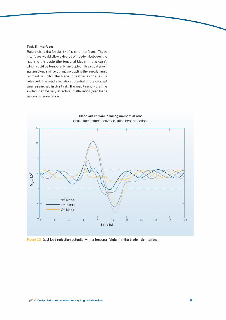
51 Design limits and solutions for very large wind turbines
Task 5: Interfaces
Researching the feasibility of ’smart interfaces’. These
interfaces would allow a degree of freedom between the
hub and the blade (the torsional blade, in this case),
which could be temporarily uncoupled. This could allevi-
ate gust loads since during uncoupling the aerodynamic
moment will pitch the blade to feather as the DoF is
released. The load alleviation potential of the concept
was researched in this task. The results show that the
system can be very effective in alleviating gust loads
as can be seen below.
Figure 12: Gust load reduction potential with a torsional "clutch" in the blade-hub-interface.
MY x
10
-6
Time [s]
14
12
8
4
0
-4
-8 0 2 4 6 8 10 12 14 18 18 20
1st blade
2nd blade
3rd blade
Blade out of plane bending moment at root
(thick lines: clutch activated, thin lines: no action)
v3_21895_UpWind Report_AttentionGraphDisparaissent.indd 51v3_21895_UpWind Report_AttentionGraphDisparaissent.indd 51 2/03/11 15:162/03/11 15:16
March 201152
3 UpWind: Technology integration
• Barlas T.K., and van Kuik G.A.M., Review of state
of the art in smart rotor control research for wind
turbines, Progress in Aerospace Sciences, Volume
46, Issue 1, January 2010, Pages: 1-27.
• Boeije, de Vries, Cleine, van Emden, Zwart,
Stobbe, Hirschberg, Hoeijmakers, “Fluidic Load
Control for Wind Turbine Blades,” AIAA paper
2009-684, January 2009.
• Frost M., Sedlak P., Sippola M. and Sittner P.,
"Thermomechanical model for NiTi shape
memory wires", Smart Mater. Struct. 19 (2010)
094010, doi: 10.1088/0964-1726/19/9/094010.
• Grzędziński J., and Mróz A., Gust load reduction
concept in wind turbines, Wind Energy, Volume
13, Issue 2-3, March - April 2010, Pages: 267-274.
• Heller L., et al., "Quasistatic and Dynamic
Functional Properties of Thin Superelastic Wires",
Eur. Phys. J. Spec. Top., 2008, 128, p 7–15.
• Heller L., et al., "Thermomechanical
Characterization of Shape Memory Alloy Tubular
Composite Structures", Advances in Science and
Technology, Volume 59 (2008), pp. 150-155.
• Hulskamp A.W., van Wingerden J.W., Barlas
T., Champliaud H., van Kuik G.A.M., Bersee
H.E.N., and Verhaegen M., Design of a scaled
wind turbine with a smart rotor for dynamic
load control experiments, Wind Energy, 2010,
Published online, DOI: 10.1002/we.424.
• Hulskamp A.W., and Bersee H.E.N.,
Implementation of the ‘smart’ rotor concept,
in: Wind Power Generation and Wind Turbine
Design, Edited by Tong, WIT Press, 2010.
• Lutz Th., Herrig A., Würz W., Kamruzzaman
M., and Krämer E.: Design and Wind-Tunnel
Verifi cation of Low-Noise Airfoils for Wind
Turbines, AIAA Journal Vol. 45, No. 4, April 2007.
• Smid, van Noort, Hirschberg, van Emden, de
Vries, Stobbe, Zwart, Hoeijmakers, “Experimental
Study of Fluidic Control of a Diffusor: infl uence
of slit geometry,” AIAA paper 2009-742, January
2009.
• van Wingerden J.-W., Hulskamp A. W., Barlas
T., Marrant B., van Kuik G. A. M., Molenaar D-P.
and Verhaegen M., Proof of concept of a `smart'
wind turbine rotor blade for load reduction, Wind
Energy, Volume 11, 2008.
• van Wingerden J.-W., Hulskamp A. W., Barlas
T., Houtzager I., Bersee H., van Kuik G., and
Verhaegen M., Two-degree-of-freedom active
vibration control of a prototyped `smart' rotor,
Journal of IEEE transactions on controls system
technology, published online, 2010.
More papers have been submitted to different
journals and are awaiting review or publication.
• Barlas T. K. and van Kuik G. A. M., Aeroelastic
modeling and comparison of advanced active
fl ap control concepts for load reduction on the
Upwind 5MW wind turbine, Proceedings of the
EWEC 2009, Marseille, France.
• Barlas T., van Wingerden J.-W., Hulskamp T.,
van Kuik G., Verhaegen M., and Bersee H., Smart
dynamic rotor control: Part 2, aeroelastic analysis.
Proceedings of the Conference on The Science of
making torque from wind conference, June 2010,
Heraklion, Greece.
• Berg D., Wilson D., Reson B., Berg, J., Barlas T.,
Halse C., and Crowther A., System ID modern
control algorithms for active aerodynamic
load control and impact on gearbox loading,
Proceedings of the Conference on the Science of
Making Torque from Wind, June 2010 , Heraklion,
Greece.
• Capellaro M., Modeling of an Analytically
Determined Bend Twist Coupled Blade, EAWE
2007 Pamplona, Spain.
References: Journal papers and book chapters
Conference proceedings
v3_21895_UpWind Report_AttentionGraphDisparaissent.indd 52v3_21895_UpWind Report_AttentionGraphDisparaissent.indd 52 2/03/11 15:162/03/11 15:16
53 Design limits and solutions for very large wind turbines
• Capellaro M. and Kühn M., Aeroelastic design and
simulation of a bend twist coupled wind turbine
rotor blade, DEWEK 2008 Bremen, Germany.
• Capellaro M. and Kühn M., Boundaries of Bend
Twist Coupled Blades, Science of Making Torque
from the Wind 2010, Heraklion Greece.
• Grzedzinski J., Mróz A., Gust load reduction
concept in wind turbines, IV ECCOMAS Them
Conf Smart Structures and Materials SMART'09,
Porto, Portugal
• Hulskamp A.W. and Bersee H.E.N., A Shape
Memory Alloy Activated Morphing Surface for
Aerodynamic Load Control on Wind Turbine
Rotor Blades, 20th International Conference on
Adaptive Structures and Technologies, October
20-22, 2009, Hong Kong.
• Hulskamp A.W., Champliaud H., Wingerden J.W.,
Barlas T., Bersee H., van Kuik G., and Verhaegen
M.. Smart dynamic rotor control: Part1, design
of a smart rotor. Proceedings of the Conference
on The Science of making torque from wind
conference, June 2010, Heraklion, Greece.
• Kamruzzaman M., Lutz Th., Krämer E.: An
Approach to RANS Based Prediction of
Airfoil Trailing Edge Far-Field Noise, Second
International Meeting on Wind Turbine Noise,
Lyon, France, September 20-21, 2007.
• Kamruzzaman M., Lutz Th., Herrig A., Krämer
E.: RANS Based Prediction of Airfoil Trailing
Edge Far-Field Noise: Impact of Isotropic and
Anisotropic Turbulence, AIAA paper 2008-2867,
14th AIAA/CEAS Aeroacoustics Conference,
Vancouver, Canada, 5 - 7 May 2008.
• Kamruzzaman M., Herrig A., Lutz Th., Würz W.,
Krämer E., Wagner S.: Comprehensive Evaluation
and Assessment of Trailing Edge Noise Prediction
Based on Dedicated Measurements, 3rd
International Conference on Wind Turbine Noise,
17-19 June, Aalborg, Denmark, 2009.
• Kamruzzaman M., Lutz Th., Ivanov A., Herrig
A., Würz W., Krämer E.: Evaluation of Measured
Anisotropic Turbulence Two-point Correlation
Data for the Accurate Prediction of the
Turbulence Noise Sources, AIAA paper 2009-
3313, 15th AIAA/CEAS Aeroacoustics
Conference, Miami, USA, 11-13 May, 2009.
• Kamruzzaman M., Meister K., Lutz Th., Kühn
M., Kraemer E.: Wind Turbine Aerodynamics
and Aeroacoustics at University of Stuttgart - An
Overview of Research and Development, 1st Int.
Conf. on the Developments in Renewable Energy
Technology (ICDRET'09), Dhaka, Bang-ladesh,
December 17-19, 2009.
• Kamruzzaman M., Lutz Th., Herrig A., Krämer E.:
Semi-empirical Modeling of Turbulent Anisotropy
for Airfoil Self Noise Prediction, Submitted to
16th AIAA/CEAS Aeroacoustics Conference,
Sweden, 7 - 9 Jun, 2010.
• Sedlák P., Frost M., "Two dimensional
thermomechanical model for combined loading
of NiTi wire structures". Proceedings of the ASME
2009 Conference on Smart Materials, Adaptive
Structures and Intelligent Systems SMASIS2009,
September 20-24, 2009, Oxnard, California, USA.
• Sippola M. and Lindroos T., Modeling and testing
of a load-limiting sandwich structure, ESOMAT
2009.
• Sippola M., Lindroos T., Sedlak P., Frost M.,
Finite element modeling of shape memory alloy
actuated FRP Laminate structures using the irloop
sma model in abaqus, THERMEC 2009.
• van Wingerden J.-W., Barlas T., Hulskamp T.,
Bersee H., Verhaegen M., and van Kuik G., Smart
dynamic rotor control: Part 3, advanced controller
design. Proceedings of the Conference on The
Science of making torque from wind conference,
June 2010, Heraklion, Greece.
• Wilson D. Reson B., Berg D., Barlas T. and
van Kuik G. A. M., Active aerodynamic blade
distributed fl ap control design procedure for load
reduction on the UpWind 5MW wind turbine,
Proceedings of the 48th AIAA/ASME, Orlando,
FL, U.S.A.
v3_21895_UpWind Report_AttentionGraphDisparaissent.indd 53v3_21895_UpWind Report_AttentionGraphDisparaissent.indd 53 2/03/11 15:162/03/11 15:16

March 201154
3.4 Work Package 1B4: Upscaling
Challenges and main
innovations
The wind turbine market has grown rapidly together
with the capacity of wind farms and the size of wind
turbines. The upscaling trend refl ects the market real-
ity, where the average wind turbine size is constantly
increasing. Upscaling is performed to harness a larg-
er resource, and benefi t from economies of scale.
As a result, during the last two decades wind turbines
have grown in capacity from 250 kW to 6-7 MW in size
from a 25 m rotor diameter to over 125 m. Recent
announcements were made regarding 10 MW tur-
bines, which should be tested in the coming years.
No agreement has been reached yet on the optimal
capacity of a wind turbine or how far upscaling can
be performed. The uncertainty about the maximum
achievable dimensions depends on load mitigation,
controllability, and innovative materials and structures.
With the growing size of turbines, the technology has
developed rapidly. Constant speed, stall-controlled
machines with fi xed blade pitch equipped with in-
duction directly connected to the grid dominated the
market in the early days. Nowadays these are no
longer produced. Variable speed turbines with indi-
vidual blade pitch systems which are connected to
the grid via power electronics are becoming a main-
stream.
For land application, transportation, installation and
sitting limitations might limit the maximum size of
wind turbines, contrary to offshore applications.
To enable the future targets for implementation of
wind energy to be met, offshore wind energy will need
to become more competitive. Due to the capital cost
structure of wind farms offshore, dominated by the
cost of support structures and foundations, offshore
applications could require wind turbines to be as large
as possible.
The UpWind project focused on investigating the
feasibility and limits of reliable and effi cient large
concepts. The objective of the within the upscaling
work package activities is to identify R&D needs for
the expanding future market of large scale machines.
The optimum technology and economics of future
wind turbines, varying in size and concept and for
various applications, needed to be analysed. This re-
quired a value for the innovations and developments
for all developments that are being investigated in
UpWind. The UpWind investigated a lighthouse vision
defi ning the options and necessities for future very
large wind turbines.
“ Is bigger cheaper? How far can we go in upscaling?
Yes, we have the technology but the economics will
decide. UpWind compared 20 MW designs, with
and without including the UpWind innovations
and compared them with present technology.
Costs models will tell us the way forward. ”
Bernard Bulder, Work Package Leader, Energy Research Centre of the Netherlands (ECN)
3 UpWind: Technology integration
v3_21895_UpWind Report_AttentionGraphDisparaissent.indd 54v3_21895_UpWind Report_AttentionGraphDisparaissent.indd 54 2/03/11 15:162/03/11 15:16

55 Design limits and solutions for very large wind turbines
This required a cost analysis of wind turbines, and
the relation between cost, size and power rating,
and some other major cost components are taken
into consideration. Three major cost components
were analysed in this respect: ex-factory costs like
transportation, installation and operating and main-
tenance. Based on engineering cost models and
models based on scaling laws, component and total
system “ex-factory” costs are estimated. Evaluation
of transportation, installation, operating and mainte-
nance costs indicate the economics of wind energy
for very large turbines of present day technology.
The outline design, based on scaling trends and
experienced engineering judgment and cost analysis
of a 20 MW wind turbine, reveals major problem areas
in upscaling current design concepts. Fundamental
techno-economical barriers are identifi ed and new,
disruptive technology must be developed to design
very large machines of a rated power between 10 to
20 MW, with a rotor diameter between 175 to 250 m.
The fi nal results include a description of the upscal-
ing process and the identifi cation of major barriers
and options to break through these barriers. An
outline design and a cost analysis of a 20 MW wind
turbine based on the upscaling of current technology is
compared to integrating the innovative developments
of the UpWind project.
A vision on promising concepts for the future (off-
shore) market is formulated and a road map towards
identifying the requirements making the develop-
ment of larger wind turbines technically and possibly
economically viable.
Activities
Based on a systematic analysis of the growth in the
scale of wind turbines over the last decades, a scaling
model was developed, based on classical scaling
relations compared with actual trends to characterise
key design parameters as a function of turbine size.
This model characterises technological developments
in over four rotor blades and wind turbine towers.
The key scaling parameters includes the mass, rated
capacity and cost of major components as well as the
complete turbine system, cost per rated kW, and cost
per unit rotor swept area.
The scaling trends are used to outline a reference
20 MW design, based on the upscaling of the 5 MW
reference UpWind turbine. The reference wind turbine
is an artifi cial wind turbine representative for the
current largest machines on the market: 5 MW rated
power, 126 m rotor diameter, three-blades, variable
speed and power control by pitch to vane. Virtual
upscaled designs are created based on scaling
models and optimised with present technology.
A critical assessment of the upscaled design will be
undertaken in order to determine the engineering
feasibility, cost implications, investment risks and
overall fundamental barriers, as concerns technology,
design tools and concept, which might prevent such
large scale wind turbines. The identifi ed barriers may
be related to the cost of energy, the manufacturing
process, the installation process, the structural
integrity, etc. The identifi ed barriers will be used
to give direction to the future long term research
activities. The results from economic analyses and
the conceptual evaluations can be used to inspire the
development activities of industry.
In parallel with the upscaling of the reference wind
turbine, the innovative developments in UpWind are
evaluated regarding their impact on the cost of energy.
Promising concepts for future very large offshore
wind turbines are being investigated. For the offshore
market the ease of installation and maintenance and
the robustness of the design are far more important
than for onshore. The typical offshore design drivers
are likely to result in quite a different optimum concept
from present common technology.
v3_21895_UpWind Report_AttentionGraphDisparaissent.indd 55v3_21895_UpWind Report_AttentionGraphDisparaissent.indd 55 2/03/11 15:162/03/11 15:16
March 201156
UPWIND: RESEARCH ACTIVITIES4
Photo
: RES
Gro
up
v3_21895_UpWind Report_AttentionGraphDisparaissent.indd 56v3_21895_UpWind Report_AttentionGraphDisparaissent.indd 56 2/03/11 15:162/03/11 15:16

57 Design limits and solutions for very large wind turbines
.UpWind: Research activities
2 Aerodynamics and aeroelastics
3 Rotor structures and materials
4 Foundations and support structures
5 Control systems
6 Remote sensing
7 Condition monitoring
8 Flow
9 Electrical grid
WP Number
Work Package
2 Aerodynamics and aero-elastics
3 Rotor structure and materials
4 Foundations and support structures
5 Control systems
6 Remote sensing
7 Condition monitoring
8 Flow
9 Electrical grid
10 Management
1A1 1A3 1B1 1B2 1B3 1B4
Integrated
des
ign ap
proa
ch
and stan
dards
Scientifi c integration Technology integration
Metrology
Inno
vativ
e rotor b
lade
s
Tran
smission
and
con
version
Smar
t rotor blade
s
Upsc
aling
1A2
Training
and
edu
catio
n
v3_21895_UpWind Report_AttentionGraphDisparaissent.indd 57v3_21895_UpWind Report_AttentionGraphDisparaissent.indd 57 2/03/11 15:162/03/11 15:16

March 201158
4 UpWind: Research activities
4.1 Work Package 2:
Aerodynamics and aeroelastics
Challenges and main
innovations
Upscaling of wind turbines has several fundamental
implications on the aeroelastic modelling. UpWind
investigated an aerodynamic and aeroelastic design
basis for large multi-MW turbines. With upscaling,
the fl exibility of the wind turbine structure increases
so that more eigen-frequencies coincide with peaks
in the aerodynamic load input, and the self induced
loads, e.g. from elastic torsion of the blades, become
more important.
Another effect of upscaling is that an increasing part
of the scales in the natural turbulence are compa-
rable with the rotor diameter and become concen-
trated at multiples of the rotational frequency (1p).
This leads to bigger variations in dynamic induction
over the rotor disc, which also originates from atmos-
pheric shear and wake effects, as well as from the
increased eigen-motion of the blades and possibly
from distributed control.
The fi nal outcome of this work is a design-basis con-
sisting of tools and methods for aerodynamic and
aeroelastic design of future large multi-MW turbines
covering possible new and innovative concepts.
A consensus was created regarding intelligent blade
concepts, supported by the tools developed in UpWind.
Different aspects were investigated:
The importance of non-linear structural effects on
loads and stability was quantifi ed, and tools were
developed to account for it. UpWind demonstrat-
ed that bending-torsion coupling is important and
can be tailored to reduce fatigue loads. We could
reduce the loads by 10% in fl apwise direction by
using more fl exible materials or bending the
blades. Fore-bended blades today appearing on
the market are therefore highly benefi cial, as fore
pre-bending is benefi cial with respect to stability;
Shear-coupling and large deformation into beam
and fi nite elements models were included.
UpWind showed infl ow shear causes dynamic in-
duction and creates phase shifts, which should
be included in models. Phase shifts accounts for
10% of the fatigue loads in current BEM codes
and this effect becomes more important for larg-
er turbines. As well, ground effect is signifi cant
in shear and should be included in models to
increase effi ciency;
“ Upscaling changes the wind turbine dynamic
behaviour. UpWind investigated fundamental
aspects related to coupling aerodynamic and
aeroelastic modeling. The new reliable models
enabled the proposition of innovative development
paths. They demonstrated the perspectives of
intelligent blade concepts, and advanced blade
designs. ”
Flemming Rasmussen, Work Package Leader, Risø DTU
v3_21895_UpWind Report_AttentionGraphDisparaissent.indd 58v3_21895_UpWind Report_AttentionGraphDisparaissent.indd 58 2/03/11 15:162/03/11 15:16

59 Design limits and solutions for very large wind turbines
Engineering aerodynamic models by application
of full 3D unsteady CFD models in complex infl ow
such as strong wind shear were analysed and
developed. There, stability analysis including non-
linear effects (and structural modal damping pre-
diction) show that coupling effects are important;
Overview of requirements to aerodynamic and
aeroelastic design tools in order to predict the
potential of different advanced control features
and aerodynamic devices. Here, dynamic stall
models for the variable trailing edge concept were
developed and applied for aeroelastic predictions.
Fatigue load reductions of 20 – 40% have been
identifi ed;
Development of concepts to improve the link
between CFD and aeroacoustic predictions.
Results show boundary layer predictions and
measurements are in reasonable agreement
with advanced UpWind methods.
Research activities and results
Structural dynamics — large defl ections and
non-linear effects
Aeroelastic tools that account for important non-
linear structural and geometric effects were devel-
oped and applied to estimate the importance for
loads and stability of the blades. The structural
modelling capabilities were advanced by developing
new beam models that account for the detailed inner
structure (complex laminates and sandwich skins).
It was identifi ed that the torsional deformation was
affected by the coupling of the blade torsion with the
blade bending and should be taken into account in
the modeling of large fl exible blades.
This is illustrated in Figure 13, which shows that
the tip pitch is up to about one degree different due
to non-linear effects. With respect to the geometri-
cal non-linearities, it was found that the bending-
torsion coupling drives differences in the response
of pre-curved blades as compared to straight ones.
So-fore blade pre-bend reduces torsion loads and
increases the blade stability. On the contrary, aft pre-
bend reduces the damping of the low damped edge-
wise modes. Pre-sweeping the blades also drives a
bending/torsion coupling which leads to nose down
torsion deformation and reduced fatigue loads in aft
pre-sweep confi gurations. The opposite effect is ob-
tained for forward sweep.
Advanced aerodynamic models
Results from different levels of aerodynamic models
have been compared. The advanced models show
that the induction varies for the blade in different
azimuthal positions when there is shear in the in-
fl ow, due to the skew vortex sheets. BEM models
should be implemented such that they model the
local infl ow and load distribution on the rotor. Another
fl ow mechanism observed in the simulations of infl ow
with strong shear is a considerable interaction with
the ground. There is a speed-up of the fl ow below
the rotor due to the constraint from the ground on
the fl ow expansion. This means that the ground infl u-
ences the aerodynamics of the rotor.
Figure 13: Predicted torsional deformation of blade
(5 MW) by beam model taking different nonlinear
effects into account.
Time [s]
1
0,5
0
-0,5
-1 0 5 10 15 20
1st order beam2nd order beam - 02nd order beam - 12nd order beam - 2
Tors
ion a
ngle
et
bla
de t
ip [
deg]
Time [s]
v3_21895_UpWind Report_AttentionGraphDisparaissent.indd 59v3_21895_UpWind Report_AttentionGraphDisparaissent.indd 59 2/03/11 15:162/03/11 15:16

March 201160
Shear due to the wake from an upstream turbine is
another example of a complex infl ow case with con-
siderable variations of loading and induction across
the rotor disc, as shown in Figure 14. For the BEM
type codes this requires a computation of induction
that is a function of both radial and azimuthal position.
Aerodynamic and aeroelastic modeling of advanced
control features and aerodynamic devices
Unsteady aerodynamic models for the simulation of
a variable trailing edge fl ap have been developed and
incorporated in aeroelastic simulation tools to identify
the potentials with respect to load reduction or pow-
er enhancement. The variable trailing edge fl ap has
proved to be an effi cient way to control the loading
on a blade. There is a good agreement between the
simple engineering model and the computationally
more demanding methods, indicating that the engi-
neering type of modeling is adequate for modeling
the 2D behaviour of airfoil sections with trailing edge
fl aps. The aeroelastic simulations indicate that loads
could be reduced between 20 and 40% by application
of this concept to large MW turbines.
Aeroelastic stability and total damping prediction
including hydroelastic interaction
Stability tools have been developed to account for
large blade defl ections. Defl ection of the long slen-
der blades results in coupling between the different
defl ections and thus changes stability characteristics.
As an example, the damping of the fi rst edgewise is
decreased due to the fl ap wise blade deformation,
and it becomes negative damped at a much lower
rotor speed than the fl utter speed. It is the geo-
metrical coupling with blade torsion that explains the
decreased and even negative aerodynamic damping
of the fi rst edgewise bending mode. For deformed
blade the edgewise bending-torsion coupling changes
as the rotor speed increases leading to a change in
looping direction and thus a change in aerodynamic
damping.
Computation of aerodynamic noise
An extensive assessment and step-by-step validation
of different prediction schemes as developed by vari-
ous partners have been conducted by comparison to
detailed measurements of turbulent boundary-layer
properties, wall pressure fl uctuations and far-fi eld
trailing-edge noise. New schemes have been devel-
oped that allows direct derivation of the turbulence
properties by means of different turbulence models
and consider anisotropy features of the fl ow. It was
found that the isotropic version of the Rnoise and
RISOE-CFD code produce almost the same results
if RANS predicted turbulence data are identical.
The improved anisotropic prediction scheme provides
the best results on the condition that the turbulence
noise source parameters are estimated properly
including turbulence anisotropy effects. The accuracy
and consistency of the prediction schemes, there-
fore, completely depends on the accurate RANS sim-
ulation results. LES-CAA computations show good
agreement with measurements in the frequency
region higher than 1~kHz whereas it over-predicts
the sound pressure level in the low frequency region.
4 UpWind: Research activities
Figure 14: Half wake fl ow case at 3D downstream
simulated with a full 3D CFD code. Contour of axial
velocity is shown together with a contour of vorticity
(the vortices).
v3_21895_UpWind Report_AttentionGraphDisparaissent.indd 60v3_21895_UpWind Report_AttentionGraphDisparaissent.indd 60 2/03/11 15:162/03/11 15:16
61 Design limits and solutions for very large wind turbines
4.2 Work Package 3:
Rotor structures and materials
Challenges and main
innovations
For larger wind turbines, the potential power yield scales
with the square of the rotor diameter, but the blade mass
scales to the third power of rotor diameter (square-cube
law). With the gravity load induced by the dead weight of
the blades, this increase of blade mass can even pre-
vent successful and economical employment of larger
wind turbines. In order to meet this challenge and allow
for the next generation of larger wind turbines, higher
demands are placed on materials and structures. This
requires more thorough knowledge of materials and
safety factors, as well as further investigation into new
materials. Previous projects have emphasised the ne-
cessity for improved and detailed fatigue life modeling
for reliable and optimal blade design. In addition, it
has become clear that knowledge on the behaviour of
larger scale subcomponents might be indispensable in
the blade design process. Furthermore, a change in the
whole concept of structural safety of the blade might be
required. UpWind investigated several aspects:
Improvement of both empirical and fundamental
understanding of materials and extension of the
OPTIDAT material database, including a simplifi ed
life-cycle analysis. The extended database was
used to develop an integrated material model
based on both tests and micro-mechanics. Design
and test recommendations are established. Micro
scale analysis and microstructure optimization
represent an important source of the future opti-
mization of the blade materials.
Study on effective blade details. A structure, repre-
senting a structural blade detail, e.g. shear web/
spar cap construction was manufactured, tested,
analysed numerically and with the assistance of
NDT methods, to improve understanding of the
structural behaviour of such a detail. This type of
blade details can be tested before performing full
scale testing.
Establishment of damage tolerant design concepts
and probabilistic strength analysis. A shell-based
fi nite element numerical methodology for life predic-
tion as well as residual strength was developed. The
numerical simulations were compared to experi-
ments. Two numerical methodologies were devel-
oped to analyse the probability of failure on layer
level. Simulations were performed to compute the
probability failure along the profi le of a 26 m blade.
Analysis of scaling limits for large blades show the
future need for new structural designs, improved
material models, manufacturing processes and/or
breakthroughs in material development can lead to
more accurate determination of the partial material
safety factors.
“ Upscaling the current designs with the existing
technology has its limits. New designs and/or
materials are needed. But UpWind found a way
forward, as better knowledge of material behaviour,
advanced methods for the structural design and
improved manufacturing processes could help in
releasing the material safety factors.”
Bert Janssen, Work Package Leader, Energy Research Centre of the Netherlands (ECN), Wind Energy Department
v3_21895_UpWind Report_AttentionGraphDisparaissent.indd 61v3_21895_UpWind Report_AttentionGraphDisparaissent.indd 61 2/03/11 15:162/03/11 15:16

March 201162
4 UpWind: Research activities
Results
Task 1: Applied (phenomenological) material model
In order to serve as a basis for advanced material mod-
els, the existing OPTIDAT database is extended with
new materials. The results of this task enable valida-
tion of the models derived in task 2 and serve as input
data for UpWind activities. Together with the work car-
ried out in 2, the result is an integrated material model,
based on both tests and micro-mechanics, for which
design recommendations and material test recommen-
dations are established, Figure 15.
Test methods for static compression, fatigue and static
shear were reviewed and compared qualitatively and
quantitatively. These results provide valuable input for
refi nement of test procedures and design recommenda-
tions.
Extensive experimental work was done at off-reference
conditions, performing tests on reference specimens in
an attempt to decouple the temperature and frequency
effects, for use in the integral material model.
In collaboration with the Condition Monitoring activities,
research was carried out on the applicability of fi bre
optical strain measurement techniques. The possibility
of embedded strain gauges was the subject of strength
and fatigue experiments.
A structure, representing a structural blade detail, e.g.
shear web/spar cap construction, was manufactured,
tested, analysed numerically and with the assistance
of NDT methods, to improve understanding of the struc-
tural behaviour of this detail, Figure 16.
Figure 16: Subcomponent testing and modelling
Am
plitu
de o
f cy
clic
str
ess
[M
Pa]
Mean cyclic stress [MPa]
700
600
500
400
300
200
100
0
- 800 - 600 - 400 - 200 0 200 400 600 800 1000
100
1,000
10,000
100,000
1,000,000
10,000,000
Figure 15: Constant life diagram
v3_21895_UpWind Report_AttentionGraphDisparaissent.indd 62v3_21895_UpWind Report_AttentionGraphDisparaissent.indd 62 2/03/11 15:162/03/11 15:16
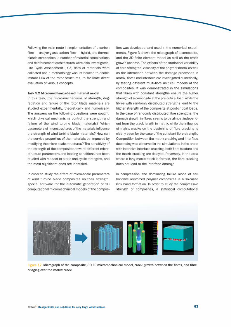
63 Design limits and solutions for very large wind turbines
Figure 17: Micrograph of the composite, 3D FE micromechanical model, crack growth between the fi bres, and fi bre
bridging over the matrix crack
Following the main route in implementation of a carbon
fi bre — and/or glass-carbon fi bre — hybrid, and thermo-
plastic composites, a number of material combinations
and reinforcement architectures were also investigated.
Life Cycle Assessment (LCA) data of materials were
collected and a methodology was introduced to enable
instant LCA of the rotor structures, to facilitate direct
evaluation of various concepts.
Task 3.2 Micro-mechanics-based material model
In this task, the micro-mechanisms of strength, deg-
radation and failure of the rotor blade materials are
studied experimentally, theoretically and numerically.
The answers on the following questions were sought:
which physical mechanisms control the strength and
failure of the wind turbine blade materials? Which
parameters of microstructures of the materials infl uence
the strength of wind turbine blade materials? How can
the service properties of the materials be improved by
modifying the micro-scale structures? The sensitivity of
the strength of the composites toward different micro-
structure parameters and loading conditions has been
studied with respect to static and cyclic strengths, and
the most signifi cant ones are identifi ed.
In order to study the effect of micro-scale parameters
of wind turbine blade composites on their strength,
special software for the automatic generation of 3D
computational micromechanical models of the compos-
ites was developed, and used in the numerical experi-
ments. Figure 3 shows the micrograph of a composite,
and the 3D fi nite element model as well as the crack
growth scheme. The effects of the statistical variability
of fi bre strengths, viscosity of the polymer matrix as well
as the interaction between the damage processes in
matrix, fi bres and interface are investigated numerically,
by testing different multi-fi bre unit cell models of the
composites. It was demonstrated in the simulations
that fi bres with constant strengths ensure the higher
strength of a composite at the pre-critical load, while the
fi bres with randomly distributed strengths lead to the
higher strength of the composite at post-critical loads.
In the case of randomly distributed fi bre strengths, the
damage growth in fi bres seems to be almost independ-
ent from the crack length in matrix, while the infl uence
of matrix cracks on the beginning of fi bre cracking is
clearly seen for the case of the constant fi bre strength.
Competition between the matrix cracking and interface
debonding was observed in the simulations: in the areas
with intensive interface cracking, both fi bre fracture and
the matrix cracking are delayed. Reversely, in the area
where a long matrix crack is formed, the fi bre cracking
does not lead to the interface damage.
In compression, the dominating failure mode of car-
bon-fi bre reinforced polymer composites is a so-called
kink band formation. In order to study the compressive
strength of composites, a statistical computational
v3_21895_UpWind Report_AttentionGraphDisparaissent.indd 63v3_21895_UpWind Report_AttentionGraphDisparaissent.indd 63 2/03/11 15:162/03/11 15:16
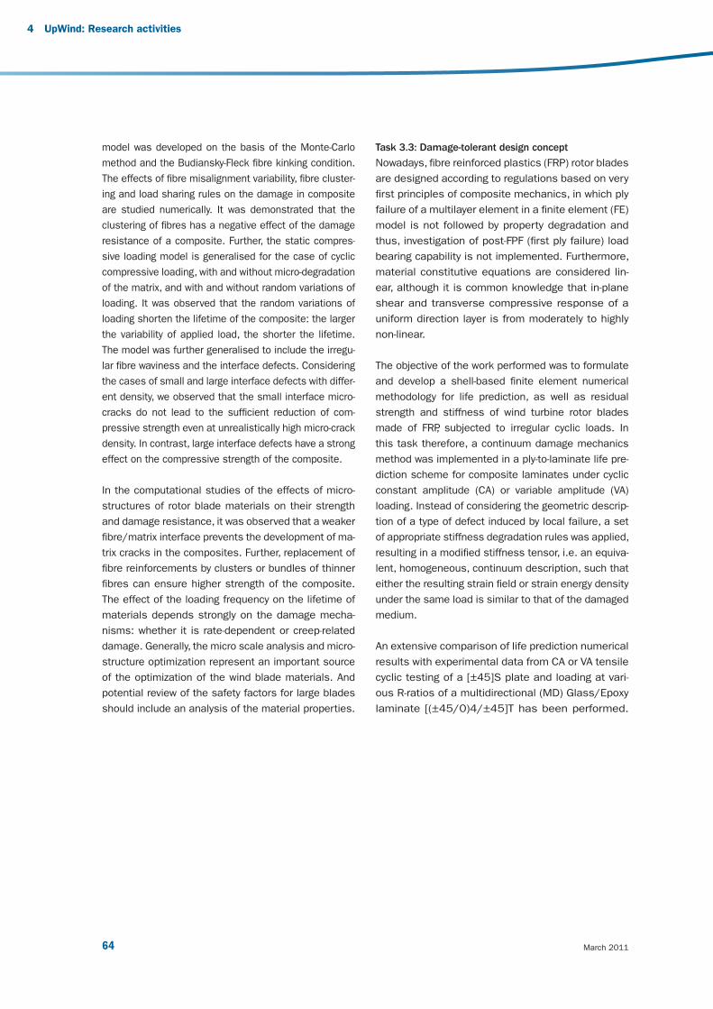
March 201164
4 UpWind: Research activities
model was developed on the basis of the Monte-Carlo
method and the Budiansky-Fleck fi bre kinking condition.
The effects of fi bre misalignment variability, fi bre cluster-
ing and load sharing rules on the damage in composite
are studied numerically. It was demonstrated that the
clustering of fi bres has a negative effect of the damage
resistance of a composite. Further, the static compres-
sive loading model is generalised for the case of cyclic
compressive loading, with and without micro-degradation
of the matrix, and with and without random variations of
loading. It was observed that the random variations of
loading shorten the lifetime of the composite: the larger
the variability of applied load, the shorter the lifetime.
The model was further generalised to include the irregu-
lar fi bre waviness and the interface defects. Considering
the cases of small and large interface defects with differ-
ent density, we observed that the small interface micro-
cracks do not lead to the suffi cient reduction of com-
pressive strength even at unrealistically high micro-crack
density. In contrast, large interface defects have a strong
effect on the compressive strength of the composite.
In the computational studies of the effects of micro-
structures of rotor blade materials on their strength
and damage resistance, it was observed that a weaker
fi bre/matrix interface prevents the development of ma-
trix cracks in the composites. Further, replacement of
fi bre reinforcements by clusters or bundles of thinner
fi bres can ensure higher strength of the composite.
The effect of the loading frequency on the lifetime of
materials depends strongly on the damage mecha-
nisms: whether it is rate-dependent or creep-related
damage. Generally, the micro scale analysis and micro-
structure optimization represent an important source
of the optimization of the wind blade materials. And
potential review of the safety factors for large blades
should include an analysis of the material properties.
Task 3.3: Damage-tolerant design concept
Nowadays, fi bre reinforced plastics (FRP) rotor blades
are designed according to regulations based on very
fi rst principles of composite mechanics, in which ply
failure of a multilayer element in a fi nite element (FE)
model is not followed by property degradation and
thus, investigation of post-FPF (fi rst ply failure) load
bearing capability is not implemented. Furthermore,
material constitutive equations are considered lin-
ear, although it is common knowledge that in-plane
shear and transverse compressive response of a
uniform direction layer is from moderately to highly
non-linear.
The objective of the work performed was to formulate
and develop a shell-based fi nite element numerical
methodology for life prediction, as well as residual
strength and stiffness of wind turbine rotor blades
made of FRP, subjected to irregular cyclic loads. In
this task therefore, a continuum damage mechanics
method was implemented in a ply-to-laminate life pre-
diction scheme for composite laminates under cyclic
constant amplitude (CA) or variable amplitude (VA)
loading. Instead of considering the geometric descrip-
tion of a type of defect induced by local failure, a set
of appropriate stiffness degradation rules was applied,
resulting in a modifi ed stiffness tensor, i.e. an equiva-
lent, homogeneous, continuum description, such that
either the resulting strain fi eld or strain energy density
under the same load is similar to that of the damaged
medium.
An extensive comparison of life prediction numerical
results with experimental data from CA or VA tensile
cyclic testing of a [±45]S plate and loading at vari-
ous R-ratios of a multidirectional (MD) Glass/Epoxy
laminate [(±45/0)4/±45]T has been performed.
v3_21895_UpWind Report_AttentionGraphDisparaissent.indd 64v3_21895_UpWind Report_AttentionGraphDisparaissent.indd 64 2/03/11 15:162/03/11 15:16
65 Design limits and solutions for very large wind turbines
As an example, in Figure 18 damage patterns in the
outer three layers of an MD coupon after 700,000
cycles were shown.
Additionally, quantifi cation of the structural reliabil-
ity level of the wind turbine blade with respect to its
strength, stiffness and elastic stability should be per-
formed in probabilistic terms by relying both on load
uncertainty quantifi cation as well as on material, due
to the use of composite materials, exhibiting great in-
herent variability of mechanical properties. To this end,
two methodologies were developed within task 3.3,
where the probability of failure is estimated on the
layer level, taking into consideration the variability of
applied loads, material strength and elasticity proper-
ties. One, based on the Edgeworth Expansion method,
allows for direct connection with currently employed
aero-elastic wind turbine design codes, while the other,
employing the Response Surface Method in combina-
tion with a fi nite element shell model, allows a more
accurate representation of the blade structure.
Figure 18: Damage modes according to Puck failure criteria of a [(±45/0)4/±45] Gl/Ep MD coupon, at a stress
level of σmax
=193 [MPa], R=0.1
v3_21895_UpWind Report_AttentionGraphDisparaissent.indd 65v3_21895_UpWind Report_AttentionGraphDisparaissent.indd 65 2/03/11 15:162/03/11 15:16

March 201166
Task 3.4: Upscaling - cost factors
Input with respect to blades and blade materials for
the identifi cation of the technological and economic
barriers associated with the dimensioning of very large
wind turbine design up to 20 MW, through upscaling of
a reference wind turbine of 5 MW were the major core
of investigation within this task. The most important
aspects addressed in these studies were:
The feasibility of increasing the number of layers or
the layer thickness, when considering that until now
the upscaling of a wind turbine, as well as the wall
thickness of the blades is linear with rotor radius, R.
The possibility of mitigating blade loads by using
other materials or other lay-ups.
The perspectives of using enhanced materials with
respect to possible blade weight reduction.
Quantifi ed possibilities and perspectives of reducing
safety factors.
The validity of a cost factor of 2.4 in the upscaling of
blades, since weight itself is not the design driver but
the costs are.
The formulation of a cost model for the wind turbine
blade, serving as an input to the overall wind turbine
cost model produced within UpWind.
Results on the discussed issues of scaling limits, of
the possibilities of new blade materials, of safety fac-
tors and of costs of several alternative materials and
blade concepts have been included in a comprehensive
report to be directly used as input for other UpWind
activities. The following results have been achieved and
are included in the report:
Thickness limitations: today’s root section thick-
ness is in the 10-15 cm range. For 20 MW blades,
with current design parameters, this thickness
could increase to 30 cm. This poses challenges
for production, as well as connection to the hub.
Possibilities for weight reductions for load mitiga-
tion, including the possibilities of other materials
and stiffness issues were indicated under current
design constraints.
Discussion on failure modes necessary for safe-
ty factors review. A comparison was performed
for the current design standards available at the
moment. Today, different levels of partial safety
factors exist, for DNV or GL, which differ from IEC.
GL uses more stringent partial safety factors, but
DNV asks for more experimental proof.
Cost issues under currently available technologi-
cal solutions. For the cost function, as has been
developed in UpWind, reference values are pro-
vided depending on the type of blade materials
and manufacturing processes.
4 UpWind: Research activities
v3_21895_UpWind Report_AttentionGraphDisparaissent.indd 66v3_21895_UpWind Report_AttentionGraphDisparaissent.indd 66 2/03/11 15:162/03/11 15:16
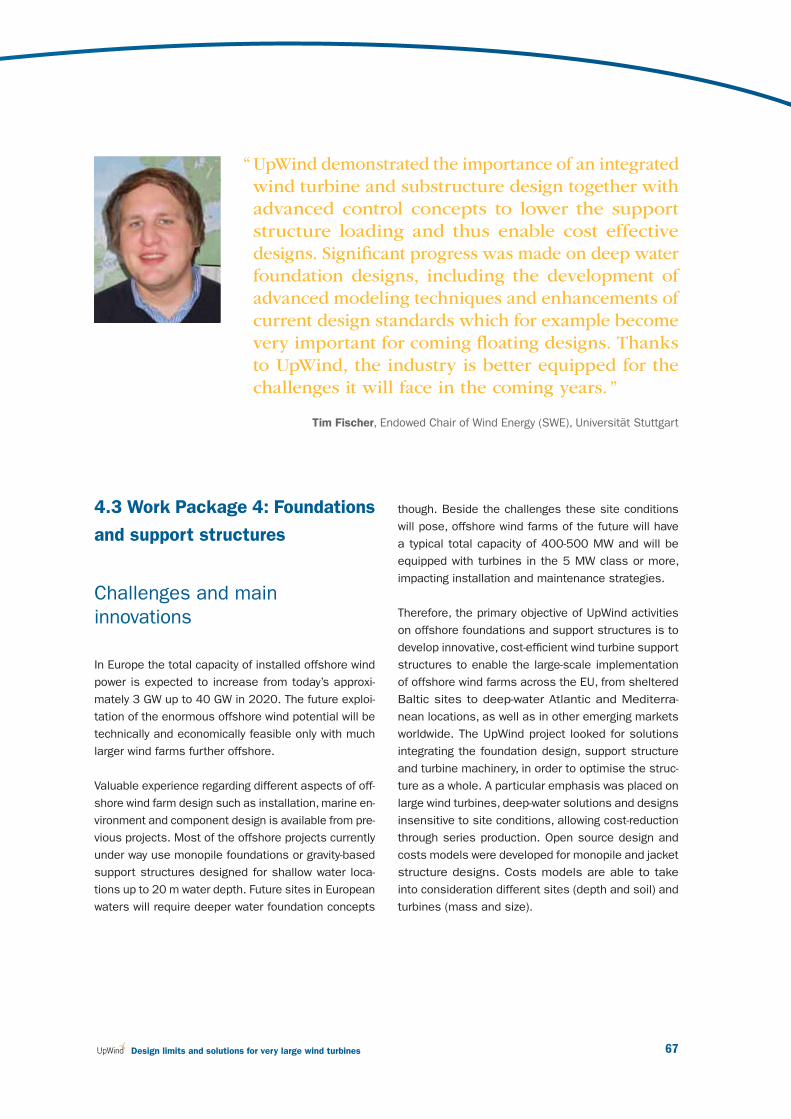
67 Design limits and solutions for very large wind turbines
4.3 Work Package 4: Foundations
and support structures
Challenges and main
innovations
In Europe the total capacity of installed offshore wind
power is expected to increase from today’s approxi-
mately 3 GW up to 40 GW in 2020. The future exploi-
tation of the enormous offshore wind potential will be
technically and economically feasible only with much
larger wind farms further offshore.
Valuable experience regarding different aspects of off-
shore wind farm design such as installation, marine en-
vironment and component design is available from pre-
vious projects. Most of the offshore projects currently
under way use monopile foundations or gravity-based
support structures designed for shallow water loca-
tions up to 20 m water depth. Future sites in European
waters will require deeper water foundation concepts
though. Beside the challenges these site conditions
will pose, offshore wind farms of the future will have
a typical total capacity of 400-500 MW and will be
equipped with turbines in the 5 MW class or more,
impacting installation and maintenance strategies.
Therefore, the primary objective of UpWind activities
on offshore foundations and support structures is to
develop innovative, cost-effi cient wind turbine support
structures to enable the large-scale implementation
of offshore wind farms across the EU, from sheltered
Baltic sites to deep-water Atlantic and Mediterra-
nean locations, as well as in other emerging markets
worldwide. The UpWind project looked for solutions
integrating the foundation design, support structure
and turbine machinery, in order to optimise the struc-
ture as a whole. A particular emphasis was placed on
large wind turbines, deep-water solutions and designs
insensitive to site conditions, allowing cost-reduction
through series production. Open source design and
costs models were developed for monopile and jacket
structure designs. Costs models are able to take
into consideration different sites (depth and soil) and
turbines (mass and size).
“ UpWind demonstrated the importance of an integrated
wind turbine and substructure design together with
advanced control concepts to lower the support
structure loading and thus enable cost effective
designs. Signifi cant progress was made on deep water
foundation designs, including the development of
advanced modeling techniques and enhancements of
current design standards which for example become
very important for coming fl oating designs. Thanks
to UpWind, the industry is better equipped for the
challenges it will face in the coming years. ”
Tim Fischer, Endowed Chair of Wind Energy (SWE), Universität Stuttgart
v3_21895_UpWind Report_AttentionGraphDisparaissent.indd 67v3_21895_UpWind Report_AttentionGraphDisparaissent.indd 67 2/03/11 15:162/03/11 15:16

March 201168
While innovative solutions for the rotor nacelle assembly
will be made available by close cooperation with other
UpWind activities, emphasis is put on the support struc-
ture and the interaction of the design of the support
structure and the rotor nacelle assembly. The research
activities were divided into three Tasks, as shown in the
table below.
The objectives of Task 1 are mitigation of dynamic
support structure loading and compensation of the
inherent variability of site conditions within a large wind
farm. Integration of the support structure design and
the turbine design and use of smart turbine control are
expected to achieve this. The task mainly focuses on
the development of control algorithms, where different
methods ranging from operational control to dynamic
control are evaluated in order to select the most prom-
ising approaches for development. Simultaneously, a
reduction of the site sensitivity of structures (e.g. dif-
ferent conditions with respect to water depth, soil, wind
and waves) is attempted by employing the control sys-
tem, structural tuning and the selection of particular
structural concepts.
In Task 2, the goal is to develop support structure con-
cepts for water depths beyond 30m through innovative
bottom-mounted concepts. In this task, current design
practice and experience are merged with the new tech-
niques from Task 1 and applied to concept development
for deeper water. The planned method is based on a
preliminary review of design and installation methods,
and a study of the range and applicability of different
foundation and support structure types, e.g. monopile
(soft-stiff or soft-soft), tripod or lattice type with soft-stiff
characteristics, and very soft compliant structures.
Finally, Task 3 aims to enhance integrated design tools
for the design of large numbers of structures at deep-
water sites, and to actively support the development of
dedicated international standards which specify best
practice for the design of offshore wind farms (e.g. site-
specifi c design, aerodynamic and hydrodynamic impact,
low-risk structures, fl oating concepts). The development
of innovative concepts in Tasks 1 and 2 requires en-
hancement of the capabilities of existing design tools
and methods with respect to the description of turbine,
support structures and site characteristics as well as the
rapid processing of many similar designs.
4 UpWind: Research activities
Task 1
Integration of support structure
and wind turbine design
Task 2
Support structure concepts for
deep water sites
Task 3
Enhancement of design methods
and standards
Develop and enhance the
integrated design process
for offshore wind turbines
Design innovative
bottom-mounted support
structures
Design tools and methods
for bottom-mounted support
structures
Control concepts for
mitigating aerodynamic
and hydrodynamic loading
Analysis of very soft structuresDesign tools and methods
for fl oating support structures
Compensation of site
and structural variability
Integration of support structure
and wind turbine design
Integration of support structure
and wind turbine design
v3_21895_UpWind Report_AttentionGraphDisparaissent.indd 68v3_21895_UpWind Report_AttentionGraphDisparaissent.indd 68 2/03/11 15:162/03/11 15:16
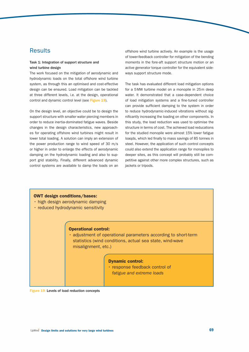
69 Design limits and solutions for very large wind turbines
Results
Task 1: Integration of support structure and
wind turbine design
The work focused on the mitigation of aerodynamic and
hydrodynamic loads on the total offshore wind turbine
system, as through this an optimised and cost-effective
design can be ensured. Load mitigation can be tackled
at three different levels, i.e. at the design, operational
control and dynamic control level (see Figure 19).
On the design level, an objective could be to design the
support structure with smaller water piercing members in
order to reduce inertia-dominated fatigue waves. Beside
changes in the design characteristics, new approach-
es for operating offshore wind turbines might result in
lower total loading. A solution can imply an extension of
the power production range to wind speed of 30 m/s
or higher in order to enlarge the effects of aerodynamic
damping on the hydrodynamic loading and also to sup-
port grid stability. Finally, different advanced dynamic
control systems are available to damp the loads on an
offshore wind turbine actively. An example is the usage
of tower-feedback controller for mitigation of the bending
moments in the fore-aft support structure motion or an
active generator torque controller for the equivalent side-
ways support structure mode.
The task has evaluated different load mitigation options
for a 5 MW turbine model on a monopile in 25 m deep
water. It demonstrated that a case-dependent choice
of load mitigation systems and a fi ne-tuned controller
can provide suffi cient damping to the system in order
to reduce hydrodynamic-induced vibrations without sig-
nifi cantly increasing the loading on other components. In
this study, the load reduction was used to optimise the
structure in terms of cost. The achieved load reducations
for the studied monopile were almost 15% lower fatigue
loaqds, which led fi nally to mass savings of 85 tonnes in
steel. However, the application of such control concepts
could also extend the application range for monopiles to
deeper sites, as this concept will probably still be com-
petitive against other more complex structures, such as
jackets or tripods.
Figure 19: Levels of load reduction concepts
OWT design conditions/bases:
• high design aerodynamic damping
• reduced hydrodynamic sensitivity
Operational control:
• adjustment of operational parameters according to short-term
statistics (wind conditions, actual sea state, wind-wave
misalignment, etc.)
Dynamic control:
• response feedback control of
fatigue and extreme loads
v3_21895_UpWind Report_AttentionGraphDisparaissent.indd 69v3_21895_UpWind Report_AttentionGraphDisparaissent.indd 69 2/03/11 15:162/03/11 15:16

March 201170
Task 2: Support structure concepts for deep water sites
The fi rst step was a review of support structure concepts
and fabrication and installation methods. A preliminary
design approach was presented and an evaluation of
the proposed support structure concepts was made on
the basis of expert opinions, showing that gravity based
foundations and monopiles were the preferred concepts
for depths up to 25 m, tripods and jackets were most
suitable for the intermediate water depths up to 60 m and
compliant and fl oating structures were most applicable
in waters beyond those depths.
Beside the above mentioned bottom-mounted designs
with the fundamental frequency in the soft-stiff range, a
study was performed to evaluate the potentials of com-
pliant structures. These structures are in the soft-soft
design region, having a fundamental frequency below
wave frequencies of appreciable energy, whereby the
structure responds in a ‘compliant’ way to wave loads.
It was found that these concepts could be attractive
when hybrid solutions of fl oating and bottom-mounted
structures are applied.
One of the fi nal results in this task was the creation of a
reference structure for the reference 5 MW turbine for a
site in 50 m water depth. The most suitable concept for
the reference structure is the jacket. The structure is in-
tended as a reference which can be used for comparison
with other support structure concepts, demonstrating
the effectiveness of design improvements and to demon-
strate the sensitivity to various design parameters. This
reference case is used by the IEA Task 30 OC4 project.
Figure 20: Different support structure concepts. From left to right: monopile, tripod, jacket, compliant, barge fl oater,
tension leg platform and spar fl oater structure.
4 UpWind: Research activities
v3_21895_UpWind Report_AttentionGraphDisparaissent.indd 70v3_21895_UpWind Report_AttentionGraphDisparaissent.indd 70 2/03/11 15:162/03/11 15:16
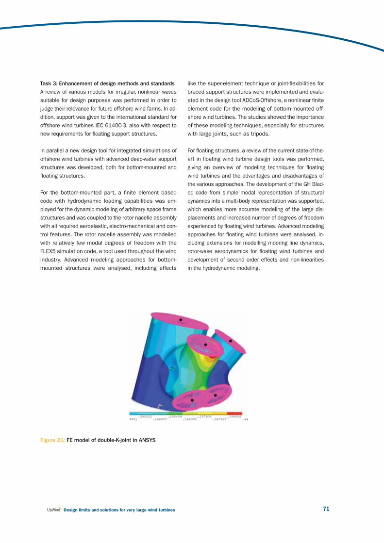
71 Design limits and solutions for very large wind turbines
Task 3: Enhancement of design methods and standards
A review of various models for irregular, nonlinear waves
suitable for design purposes was performed in order to
judge their relevance for future offshore wind farms. In ad-
dition, support was given to the international standard for
offshore wind turbines IEC 61400-3, also with respect to
new requirements for fl oating support structures.
In parallel a new design tool for integrated simulations of
offshore wind turbines with advanced deep-water support
structures was developed, both for bottom-mounted and
fl oating structures.
For the bottom-mounted part, a fi nite element based
code with hydrodynamic loading capabilities was em-
ployed for the dynamic modeling of arbitrary space frame
structures and was coupled to the rotor nacelle assembly
with all required aeroelastic, electro-mechanical and con-
trol features. The rotor nacelle assembly was modelled
with relatively few modal degrees of freedom with the
FLEX5 simulation code, a tool used throughout the wind
industry. Advanced modeling approaches for bottom-
mounted structures were analysed, including effects
like the super-element technique or joint-fl exibilities for
braced support structures were implemented and evalu-
ated in the design tool ADCoS-Offshore, a nonlinear fi nite
element code for the modeling of bottom-mounted off-
shore wind turbines. The studies showed the importance
of these modeling techniques, especially for structures
with large joints, such as tripods.
For fl oating structures, a review of the current state-of-the-
art in fl oating wind turbine design tools was performed,
giving an overview of modeling techniques for fl oating
wind turbines and the advantages and disadvantages of
the various approaches. The development of the GH Blad-
ed code from simple modal representation of structural
dynamics into a multi-body representation was supported,
which enables more accurate modeling of the large dis-
placements and increased number of degrees of freedom
experienced by fl oating wind turbines. Advanced modeling
approaches for fl oating wind turbines were analysed, in-
cluding extensions for modelling mooring line dynamics,
rotor-wake aerodynamics for fl oating wind turbines and
development of second order effects and non-linearities
in the hydrodynamic modeling.
Figure 21: FE model of double-K-joint in ANSYS
v3_21895_UpWind Report_AttentionGraphDisparaissent.indd 71v3_21895_UpWind Report_AttentionGraphDisparaissent.indd 71 2/03/11 15:162/03/11 15:16

March 201172
4 UpWind: Research activities
References
• Cordle, A., et al.: "Final report Upwind Task 4.3,
EU-UpWind-Projekt“, Del.4.3.6, Bristol, 2011.
• Cordle, A., McCann, G. and de Vries, W.: "Design
drivers for offshore wind turbine jacket support
structures", OMAE 2011 conference, Rotterdam,
2011.
• Cordle, A. and Jonkman, J.: "State-of-the-art in
fl oating wind Turbine design tools", ISOPE 2011
conference, Maui, 2011.
• De Vries, W. et al.: "Final report Upwind Task 4.2,
EU-UpWind-Projekt“, Del.4.2.8, Delft, 2011.
• De Vries, W. and Krolis, V.: “Effects of deep water
on monopile support structures” EWEC, Milan,
2007.
• De Vries, W. and van der Tempel, J.: “Quick
monopile design” EOW, Berlin, 2007.
• De Vries, W.: “Response spectrum analysis for
fatigue reduction” EWEC, Marseille, 2009.
• De Vries, W.: “UpWind deep water support
structure comparison study” EOW Stockholm
2009.
• Fischer, T., de Vries, W. and Cordle, A.: "Executive
summary – Upwind WP4 “, Stuttgart, 2011.
• Fischer, T. et al.: "Final report Upwind Task 4.1,
EU-UpWind-Projekt“, Del.4.1.5, Stuttgart, 2011.
• Fischer, T. de Vries, W. and Schmidt, B.: "UpWind
Design Basis“, Stuttgart, 2011.
• Fischer, T., deVries, W., Rainey, P., Schmid, B.,
Argyriadis, K. and Kühn, M.: “Offshore support
structure optimization by means of integrated
design and controls”, submitted to Wind Energy,
currently under revision.
• Fischer, T., de Vries, W., Rainey, P., Schmid, B.,
Argyriadis, K. and Kühn, M.: “Integration of
support structure and turbine design – Final
results of WP4-Task4.1 on offshore support
structures of the EU Upwind project”, ISOPE,
Maui, 2011.
• Fischer, T., Popko, W., Soerensen, JD. and Kühn,
M.: “Load Analysis of the Upwind jacket reference
support structure”, DEWEK, Bremen, 2010.
• Fischer, T., Rainey, P., Bossanyi, E. and Kühn, M.:
“Control strategies for offshore monopile support
structures under misaligned wind and wave
loading”, Science of Making Torque, Heraklion,
2010.
• Fischer, T. and Kühn, M.: “Importance and
mitigation of loading on offshore wind turbines
on monopile support structures in cases of non-
availability”, ISOPE, Beijing, 2010.
• Fischer, T., Rainey, P., Bossanyi, E. and Kühn, M.:
“Optimization potential for monopile support
structures using offshore-specifi c wind turbine
controls”, EOW, Stockholm, 2009.
• Fischer, T. and Kühn, M.: “Site sensitive support
structure and machine design for offshore wind
farms”, EWEC, Marseille, 2009.
• Fischer, T., Tono, A., Andersen, U. and Kühn, M.:
”Integrated design of offshore wind turbines
for compensation of site variability”, DEWEK,
Bremen, 2008.
v3_21895_UpWind Report_AttentionGraphDisparaissent.indd 72v3_21895_UpWind Report_AttentionGraphDisparaissent.indd 72 2/03/11 15:162/03/11 15:16

73 Design limits and solutions for very large wind turbines
• Fischer, T., Kühn, M. and Passon, P.:
“Load mitigation of aerodynamically and
hydrodynamically induced loads of offshore wind
turbines”, EWEC, Milan, 2007.
• Fischer, T., Passon, P. and Kühn, M.: “Control
requirements of load mitigation of aerodynamic
and hydrodynamic loads of offshore wind
turbines”, DEWEK, Bremen, 2006.
• Kaufer, D., Fischer, T., Popko, W., Vorpahl, F. and
Kühn, M.: “Different approaches to modelling
jacket support structures and their impact on
overall wind turbine dynamics”, DEWEK, Bremen,
2010.
• Matha, D.: “Model development and loads
analysis of a wind turbine on a fl oating offshore
tension leg platform”, AIAA 2010-997, ASME
Wind Energy Symposium Orlando, 2010.
• Matha, D., Jonkman, J. and Fischer, T.; "Model
development and loads analysis of a wind turbine
on a fl oating offshore tension leg platform", EOW,
Stockholm, 2009.
• Matha, D: "Model development and loads analysis
of an offshore wind turbine on a tension leg
platform, with a comparison to other fl oating
turbine concepts," NREL Report, NREL/SR-500-
45891, 2009.
• Schlipf, D., Fischer, T., Carcangiu, C., Rosetti,
M., Bossanyi, E.: “Load analysis of look-ahead
collective pitch control using LIDAR”, DEWEK,
Bremen, 2010.
• Sørensen, J.D.: “Reliability-based calibration of
fatigue safety factors for offshore wind turbines”,
ISOPE, Maui, 2011.
• Vemula, N., de Vries, W., Fischer, T., Cordle, A.
and Schmidt, B.: “Design solution for the Upwind
reference offshore support structure”, EU-
UpWind-Projekt, Del.4.2.4, Esbjerg, 2010.
• Vorpahl, F.: “Fully-coupled wind turbine
simulation including substructuring of support
structure components: Infl uence of newly
developed modeling approach on fatigue loads
for an offshore wind turbine on a tripod support
structure, ISOPE, Maui, 2011.
• Vorpahl, F, Strobel, M., Busmann, H. and
Kleinhansl, S.: “Superelement approach in fully
coupled offshore wind turbine simulation:
Infl uence of the detailed support structure
modelling on simulation results for a 5-MW
turbine on a tripod substructure, ISOPE, Beijing,
2010.
• Vorpahl, F., Blunk, M., Wingerde, A., Busmann, H.
and Kleinhansl, S.: “Implementation of a super-
element approach in a design tool for offshore
wind turbines with arbitrary support structures”,
EOW, 2009.
v3_21895_UpWind Report_AttentionGraphDisparaissent.indd 73v3_21895_UpWind Report_AttentionGraphDisparaissent.indd 73 2/03/11 15:162/03/11 15:16

March 201174
4.4 Work Package 5:
Control systems
Challenges and main
innovations
Further improvements in the cost-effectiveness of wind
turbines drives designers towards larger, lighter, more
fl exible structures, in which more ‘intelligent’ control
systems play an important part in actively reducing the
applied structural loads, avoiding the need for wind
turbines simply to withstand the full force of the applied
loads through the use of stronger, heavier and therefore
more expensive structures. UpWind activities were aimed
at further developing such control strategies and ensuring
that new, often larger and innovative turbines can be
designed to use these techniques from the start. For this
to be possible, it is important to build up full confi dence
in the effectiveness and reliability of these strategies in
all situations. Different aspects were investigated:
Individual pitch control can help to signifi cantly reduce
fatigue loading by 20-30%. This concept was demon-
strated by fi eld testing on a two-bladed turbine. This
requires reliable sensors, able to detect their own
failures. This technique can be coupled with nacelle-
mounted LIDAR sensors, able to visualise incoming
gusts, and adapt the pitch in consequence.
Dual pitch control on a single blade could signifi -
cantly reduce the loads. Pitching the tip section
more than the root section could result in a 15%
reduction in the underlying fl apwise loading. This
innovation can be combined with the ‘innoblade’
activities.
Load sensors can be used to measure loads di-
rectly, but it is also possible to estimate some loads
instead of measuring them directly. This avoids the
costs of sensor installation and maintenance, as
well as the possibility of sensor malfunction, leading
to increased overall reliability.
On-site adaptation of controllers can be per-
formed in order to adapt to variations in turbine
properties. A closed loop system identifi cation al-
gorithm was developed, in which the parameters
of a state-space turbine model are automatically
adjusted by comparing the predicted and meas-
ured responses.
To ensure fulfi lment of the different grid code re-
quirements while simultaneously ensuring that
load envelopes are not exceeded in grid fault situ-
ations, it is important to be able to model the elec-
trical dynamics accurately in conjunction with the
aerodynamics, structural dynamics and controller
dynamics of the wind turbine. A model of the elec-
trical and control parts of a doubly fed induction
generator (DFIG) turbine has been developed and
linked into a Bladed model of the turbine, and the
combined model validated against fi eld tests.
“ Larger turbines need to reduce their mass, and
intelligent control is the key. UpWind demonstrated
it is better to control the loads with intelligence
rather than building stronger, heavier structures
able to withstand those loads. Smart control of
blade pitch can achieve large load reductions, and
this has been confi rmed in fi eld tests on actual
turbines. We can now re-optimise the whole design
to improve cost effectiveness. ”
Ervin Bossanyi, Work Package Leader, Garrad Hassan and Partners Ltd. (GL-Garrad Hassan)
4 UpWind: Research activities
v3_21895_UpWind Report_AttentionGraphDisparaissent.indd 74v3_21895_UpWind Report_AttentionGraphDisparaissent.indd 74 2/03/11 15:162/03/11 15:16

75 Design limits and solutions for very large wind turbines
Wind farms can be utilised to provide voltage con-
trol for the network to which they are connected.
A supervisory VAR controller has been developed
for a large-scale wind farm to control the voltage
at the point of interconnection (POI) with the grid.
Results
Supervisory control implications of advanced control
Individual pitch control (IPC) is a promising technique for
reducing wind turbine asymmetric fatigue loads by pitch-
ing each blade individually in response to load measure-
ments. However there is also a risk of increasing extreme
loads as the blades might be pitched at different angles
during shutdowns, or as a result of failures of individual
load sensors. This work shows how these extreme load
increases can be mitigated by appropriate supervisory
control design. For example, Figure 22 shows how the
severe increase in yaw moment due to IPC during a grid
loss shutdown can be entirely mitigated by phasing out
IPC during periods of high acceleration.
Strategies for detecting failures of individual blade load
sensors were also investigated. If undetected, these could
result in signifi cant fatigue load increases if IPC action
continues regardless. Often the sensor itself would detect
its own failures, allowing the IPC to be switched off, but
an undetected failure case should still be considered.
The work has shown that by comparing the mean and
peak values of the differences between measured blade
loads over each revolution, the controller can detect such
a malfunction with a suitable degree of reliability, obviat-
ing this risk.
Figure 22: Effect on loads of phasing out IPC with rotor acceleration
Tow
er
Mz
[kN
m]
Time [s]
6000
4000
2000
0
- 2000
- 4000
- 6000
- 8000
- 10000
- 12000
Collective pitch Individual pitch (basic) Individual pitch, phasing out with rotor acceleration
0 5 10 15 20 25 30
v3_21895_UpWind Report_AttentionGraphDisparaissent.indd 75v3_21895_UpWind Report_AttentionGraphDisparaissent.indd 75 2/03/11 15:162/03/11 15:16
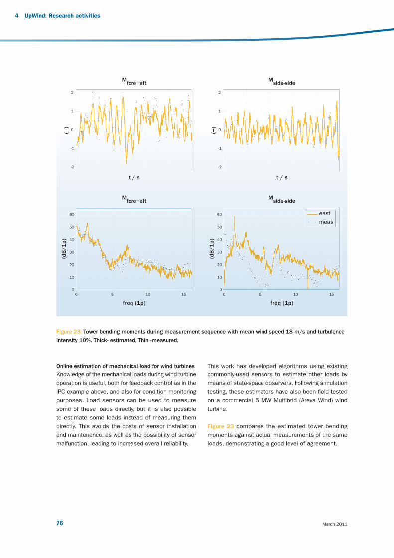
March 201176
Online estimation of mechanical load for wind turbines
Knowledge of the mechanical loads during wind turbine
operation is useful, both for feedback control as in the
IPC example above, and also for condition monitoring
purposes. Load sensors can be used to measure
some of these loads directly, but it is also possible
to estimate some loads instead of measuring them
directly. This avoids the costs of sensor installation
and maintenance, as well as the possibility of sensor
malfunction, leading to increased overall reliability.
This work has developed algorithms using existing
commonly-used sensors to estimate other loads by
means of state-space observers. Following simulation
testing, these estimators have also been fi eld tested
on a commercial 5 MW Multibrid (Areva Wind) wind
turbine.
Figure 23 compares the estimated tower bending
moments against actual measurements of the same
loads, demonstrating a good level of agreement.
Market-based analysis
Figure 23: Tower bending moments during measurement sequence with mean wind speed 18 m/s and turbulence
intensity 10%. Thick- estimated, Thin -measured.
4 UpWind: Research activities
(−)
Mfore−aft
east
meas
t / s
0 5 10 15
east
meas
t / s
Mside-side
Mfore−aft
Mside-side
freq (1p) freq (1p)
(−)
(dB
/1
p)
(dB
/1
p)
0 5 10 15
2
1
0
-1
-2
2
1
0
-1
-2
60
50
40
30
20
10
0
60
50
40
30
20
10
0
v3_21895_UpWind Report_AttentionGraphDisparaissent.indd 76v3_21895_UpWind Report_AttentionGraphDisparaissent.indd 76 2/03/11 15:162/03/11 15:16
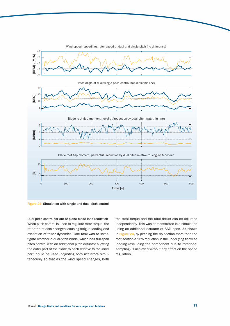
77 Design limits and solutions for very large wind turbines
Dual pitch control for out of plane blade load reduction
When pitch control is used to regulate rotor torque, the
rotor thrust also changes, causing fatigue loading and
excitation of tower dynamics. One task was to inves-
tigate whether a dual-pitch blade, which has full-span
pitch control with an additional pitch actuator allowing
the outer part of the blade to pitch relative to the inner
part, could be used, adjusting both actuators simul-
taneously so that as the wind speed changes, both
the total torque and the total thrust can be adjusted
independently. This was demonstrated in a simulation
using an additional actuator at 66% span. As shown
in Figure 24, by pitching the tip section more than the
root section a 15% reduction in the underlying fl apwise
loading (excluding the component due to rotational
sampling) is achieved without any effect on the speed
regulation.
Figure 24: Simulation with single and dual pitch control
[RP
M]
, [M
/S
][D
EG
][M
Nm
][%
]
Time [s]
18
16
14
12
10
20
15
10
5
6
4
2
0
20
10
0 100 200 300 400 500 600
Pitch angle at dual/single pitch control (fat-lines/thin-line)
Blade root fl ap moment; percentual reduction by dual pitch relative to single-pitch-mean
Blade root fl ap moment; level-at/reduction-by dual pitch (fat/thin line)
Wind speed (upperline); rotor speed at dual and single pitch (no difference)
v3_21895_UpWind Report_AttentionGraphDisparaissent.indd 77v3_21895_UpWind Report_AttentionGraphDisparaissent.indd 77 2/03/11 15:162/03/11 15:16
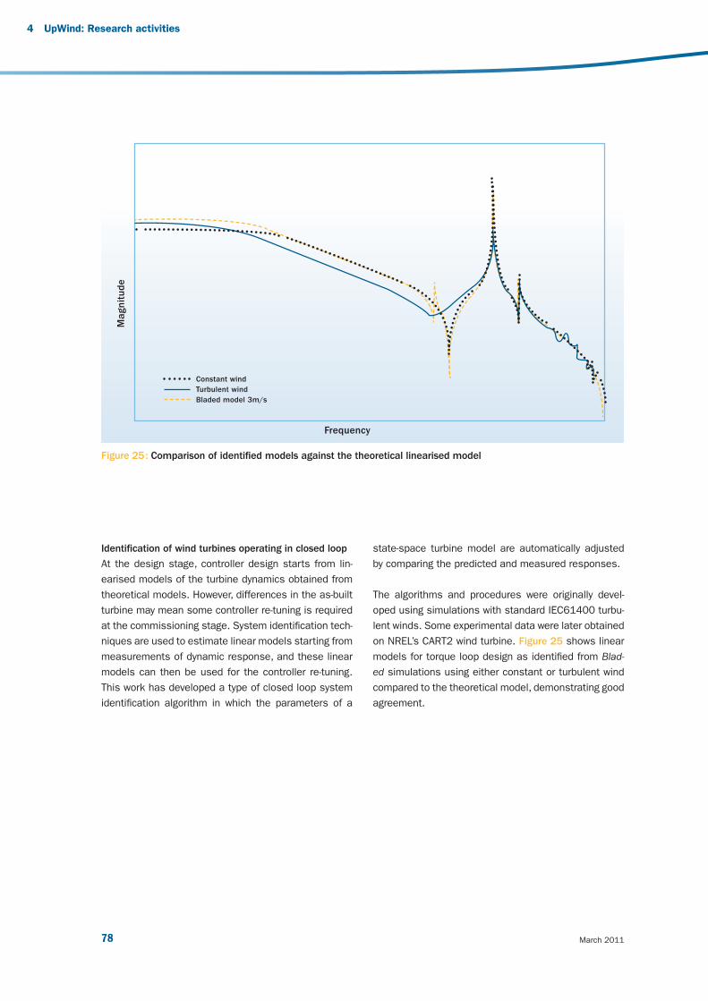
March 201178
Identifi cation of wind turbines operating in closed loop
At the design stage, controller design starts from lin-
earised models of the turbine dynamics obtained from
theoretical models. However, differences in the as-built
turbine may mean some controller re-tuning is required
at the commissioning stage. System identifi cation tech-
niques are used to estimate linear models starting from
measurements of dynamic response, and these linear
models can then be used for the controller re-tuning.
This work has developed a type of closed loop system
identifi cation algorithm in which the parameters of a
state-space turbine model are automatically adjusted
by comparing the predicted and measured responses.
The algorithms and procedures were originally devel-
oped using simulations with standard IEC61400 turbu-
lent winds. Some experimental data were later obtained
on NREL’s CART2 wind turbine. Figure 25 shows linear
models for torque loop design as identifi ed from Blad-
ed simulations using either constant or turbulent wind
compared to the theoretical model, demonstrating good
agreement.
Figure 25 : Comparison of identifi ed models against the theoretical linearised model
4 UpWind: Research activities
Magnit
ude
Frequency
Constant wind
Turbulent wind
Bladed model 3m/s
v3_21895_UpWind Report_AttentionGraphDisparaissent.indd 78v3_21895_UpWind Report_AttentionGraphDisparaissent.indd 78 2/03/11 15:162/03/11 15:16
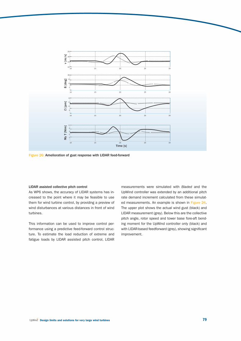
79 Design limits and solutions for very large wind turbines
LIDAR assisted collective pitch control
As WP6 shows, the accuracy of LIDAR systems has in-
creased to the point where it may be feasible to use
them for wind turbine control, by providing a preview of
wind disturbances at various distances in front of wind
turbines.
This information can be used to improve control per-
formance using a predictive feed-forward control struc-
ture. To estimate the load reduction of extreme and
fatigue loads by LIDAR assisted pitch control, LIDAR
measurements were simulated with Bladed and the
UpWind controller was extended by an additional pitch
rate demand increment calculated from these simulat-
ed measurements. An example is shown in Figure 26.
The upper plot shows the actual wind gust (black) and
LIDAR measurement (grey). Below this are the collective
pitch angle, rotor speed and tower base fore-aft bend-
ing moment for the UpWind controller only (black) and
with LIDAR-based feedforward (grey), showing signifi cant
improvement.
Figure 26: Amelioration of gust response with LIDAR feed-forward
v [m
/s]
ß [
deg]
Ω [
pm
]M
y T [
Nim
] 12
8
4
0
-4
30
20
10
5
14
12
10
8
25
20
15
10
Time [s]
10 15 20 25 30
10 15 20 25 30
10 15 20 25 30
10 15 20 25 30
v3_21895_UpWind Report_AttentionGraphDisparaissent.indd 79v3_21895_UpWind Report_AttentionGraphDisparaissent.indd 79 2/03/11 15:162/03/11 15:16

March 201180
4 UpWind: Research activities
Validation of load reducing controllers in full-scale
fi eld tests
An important task of the UpWind project is to use fi eld
tests to demonstrate that the very signifi cant load
reductions predicted with individual pitch control (IPC)
can really be achieved in practice. Previously the only
published results came from simulation models, so
fi eld test results are vital for increasing confi dence of
turbine designers to use IPC in their new designs. Field
tests of an advanced controller were carried out on
the two-bladed ‘Controls Advanced Research Turbine’
(CART2) at NREL in Colorado, USA. This demonstrated
conclusively that both IPC and fore-aft tower damping
work effectively and as predicted. Figure 27 shows
spectra of the measured shaft bending moments dur-
ing similar wind conditions with and without IPC, clearly
demonstrating the elimination of the 1P load peak.
By calculating damage equivalent loads, for 127 cam-
paigns of up to 10 minutes each and binning these
against wind speed, Figure 28 clearly demonstrates
the consistent reduction in fatigue loading with IPC ON
compared to OFF. No adjustment of the as-designed
controller was required, demonstrating the robustness
of this technique.
The fi eld tests also provided the opportunity to test a
fore-aft tower damping algorithm, and as shown in Fig-
ure 29 this also showed excellent performance, with a
large reduction of loading at the fi rst tower frequency.
This fi eld test programme is now being extended to the
three-bladed CART3 turbine. Field tests are also being
completed on a REpower turbine to test both fore-aft
and side-side damping algorithms.
Figure 27: Spectra showing reduction of 1P shaft bend-
ing moment with IPC
Figure 29: Spectra showing reduction of fore-aft tower
bending moment
02050340 OFF12.42m/s 21.55%TI
02020007 ON12.09m/s 20.70%TI
1.0e+10
1.0e+09
1.0e+08
1.0e+07
3.0e+060.0 0.5 1.0 1.5 2.0 2.5 3.0 3.5 4.0 4.5 5.0
Frequency [Hz]
Mean wind speed [m/s]
Shaft
My
SN
4 [
kN
m]
Bin averages (showing number of points)
4 6 8 10 12 14 16 18 20
280
260
240
220
200
180
160
140
120
100
22
1
1
1
1
2
2
22
34
4
1
2
2
333
3 11
1
10
6
6
6
7
6
5
5
4
4
OFF
ON
02050340 OFF12.42m/s 21.55%TI
02020007 ON12.09m/s 20.70%TI
9.0e+11
1.0e+11
1.0e+10
1.0e+09
1.0e+08
0.0 0.5 1.0 1.5 2.0 2.5 3.0 3.5 4.0 4.5 5.0
Frequency [Hz]
Figure 28: Binned results showing reduction of damage
equivalent loads with IPC
v3_21895_UpWind Report_AttentionGraphDisparaissent.indd 80v3_21895_UpWind Report_AttentionGraphDisparaissent.indd 80 2/03/11 15:162/03/11 15:16

81 Design limits and solutions for very large wind turbines
Hardware-in-the-loop testing of pitch actuators
Simulations with hardware-in-the-loop can verify the
system performance much better than a pure com-
puter simulation. A test rig has been set up with the
IWES pitch actuator test bed providing three real pitch
actuators, linked to a Bladed computer simulation of
the rest of the turbine and the incident wind fi eld using
the GH Hardware Test package to provide a conveni-
ent interface. A MATLAB/SIMULINK simulation of the
pitch bearing and gearing uses blade loads from the
real-time Bladed simulation to transfer the load to the
actuator test bed via xPC-Target. With this setup, more
confi dence can be gained in understanding the impact
of individual pitch control on the pitch actuator perfor-
mance, but the technique has the potential to improve
understanding also of other wind turbine components.
Performance of the pitch system under several wind
conditions have been run using the hardware-in-the-loop
pitch actuators, and validated against a pure computer
simulation in the same conditions. The comparison
of turbulent wind simulations in Figure 30 shows that
excellent agreement has been obtained.
Figure 30: Comparison of hardware-in-the-loop simulation (black) against pure simulation (blue) in turbulent wind.
Bla
de 1
pit
ch a
ngle
[deg]
Time [s]
12
10
8
6
4
2
0
-20 10 20 30 40 50 60
v3_21895_UpWind Report_AttentionGraphDisparaissent.indd 81v3_21895_UpWind Report_AttentionGraphDisparaissent.indd 81 2/03/11 15:162/03/11 15:16
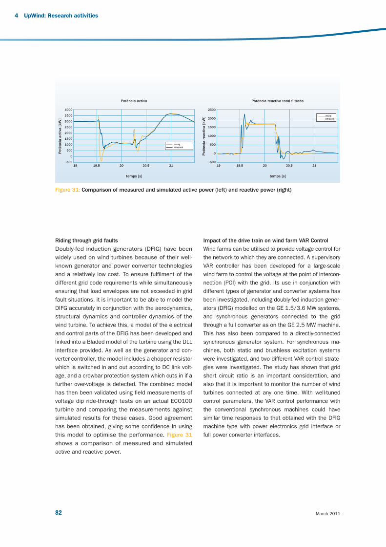
March 201182
4 UpWind: Research activities
Riding through grid faults
Doubly-fed induction generators (DFIG) have been
widely used on wind turbines because of their well-
known generator and power converter technologies
and a relatively low cost. To ensure fulfi lment of the
different grid code requirements while simultaneously
ensuring that load envelopes are not exceeded in grid
fault situations, it is important to be able to model the
DIFG accurately in conjunction with the aerodynamics,
structural dynamics and controller dynamics of the
wind turbine. To achieve this, a model of the electrical
and control parts of the DFIG has been developed and
linked into a Bladed model of the turbine using the DLL
interface provided. As well as the generator and con-
verter controller, the model includes a chopper resistor
which is switched in and out according to DC link volt-
age, and a crowbar protection system which cuts in if a
further over-voltage is detected. The combined model
has then been validated using fi eld measurements of
voltage dip ride-through tests on an actual ECO100
turbine and comparing the measurements against
simulated results for these cases. Good agreement
has been obtained, giving some confi dence in using
this model to optimise the performance. Figure 31
shows a comparison of measured and simulated
active and reactive power.
Impact of the drive train on wind farm VAR Control
Wind farms can be utilised to provide voltage control for
the network to which they are connected. A supervisory
VAR controller has been developed for a large-scale
wind farm to control the voltage at the point of intercon-
nection (POI) with the grid. Its use in conjunction with
different types of generator and converter systems has
been investigated, including doubly-fed induction gener-
ators (DFIG) modelled on the GE 1.5/3.6 MW systems,
and synchronous generators connected to the grid
through a full converter as on the GE 2.5 MW machine.
This has also been compared to a directly-connected
synchronous generator system. For synchronous ma-
chines, both static and brushless excitation systems
were investigated, and two different VAR control strate-
gies were investigated. The study has shown that grid
short circuit ratio is an important consideration, and
also that it is important to monitor the number of wind
turbines connected at any one time. With well-tuned
control parameters, the VAR control performance with
the conventional synchronous machines could have
similar time responses to that obtained with the DFIG
machine type with power electronics grid interface or
full power converter interfaces.
Figure 31: Comparison of measured and simulated active power (left) and reactive power (right)
temps [s] temps [s]
Potència activa Potència reactiva total filtrada
Potè
nci
a a
ctiv
a [
kW
]
Potè
nci
a r
eact
iva [
kW
]
19 19.5 20 20.5 21 19 19.5 20 20.5 21
4000
3500
3000
2500
2000
1500
1000
500
0
-500
2500
2000
1500
1000
500
0
-500
assaig
simulaciò
assaig
simulaciò
v3_21895_UpWind Report_AttentionGraphDisparaissent.indd 82v3_21895_UpWind Report_AttentionGraphDisparaissent.indd 82 2/03/11 15:162/03/11 15:16

83 Design limits and solutions for very large wind turbines
References
[1] Bossanyi E. Controller fi eld tests on the NREL
CART2 turbine, GH Report 11593/BR/08, www.
upwind.eu/Paginas/Publications/5%20Control%20
systems.aspx.
[2] Bossanyi E.: Controller for 5MW reference
turbine, GH report 11593/BR/04, 2009: www.
upwind.eu/Shared%20Documents/WP5%20 %20
Publications/D%205.1.1.%20Controller%20for%20
5MW%20reference%20turbine.pdf.
[3] Hau M. (2008). Promising load estimation
methodologies for wind turbine components.
Upwind Deliverable 5.2
[4] Iribas M., Landau I.D. Identifi cation of wind
turbines in closed loop operation in the presence
of three dimensional turbulence wind speed.
Wind Energy Journal 2009; 12:660-675.
[5] Jasniewicz B. (2010) Online estimation of
mechanical load for wind turbines. Upwind
Deliverable 5.3
[6] Savini B., Bossanyi E.A. “Supervisory Control
Logic Design for Individual Pitch Control”, Poster
presented at EWEC 2010, Warsaw Poland, April
20-23 2010.
[7] Schlipf D., Trabucchi, D., Bischoff O., Hofsäß M.,
Mann J., Mikkelsen T., Rettenmeier A., Trujillo J.
J., and Kühn M.: Testing of Frozen Turbulence
Hypothesis for Wind Turbine Applications with
a Scanning LIDAR System, Proc. ISARS, Paris,
France, 2010.
v3_21895_UpWind Report_AttentionGraphDisparaissent.indd 83v3_21895_UpWind Report_AttentionGraphDisparaissent.indd 83 2/03/11 15:162/03/11 15:16

March 201184
4 UpWind: Research activities
4.5 Work Package 6:
Remote sensing
Challenges and main
innovations
As wind turbines get larger, making conventional hub-
height wind measurements becomes ever more costly
as the masts get higher and higher. The challenge of
UpWind is to research remote sensing methods as a
more cost effective alternative to tall masts. One pos-
sibility is SODAR (an acoustical version of Radar), which
measures wind speed by detecting the Doppler shift of
sound waves refl ected from temperature in homogenei-
ties at different heights. LIDARs are based on a similar
technique but use instead coherent laser light backscat-
tered from suspended particles (aerosols). LIDARS are
much faster and potentially much more accurate than
SODARs. Recently new wind LIDARs have appeared on
the market, designed for performing wind measurements
over height ranges relevant to wind turbine applications.
“ Can remote sensing techniques substitute for conventional towers with the precision required by the IEC standards?
In my opinion, yes, defi nitely, but the fi rst step will probably be to use remote sensing instruments together with shorter masts. Upwind has been working actively on the current revision of the IEC standard for power curve measurement in order to achieve this aim.
How do we best exploit the freedom to measure detailed profi les offered by remote sensing techniques?
We are using the profi le information to measure more accurate and more repeatable power curves. This will ultimately reduce the uncertainty in estimating energy production. LIDARs mounted on wind turbines will also be able to see the exact ‘shape’ of the incoming wind and pro-actively control the blades to reduce loads or even to maximise the power. UpWind has been a core element for LIDAR technology development, testing and validation.
Resource assessment projects using LIDAR measurements are readily bankable as long as a suitable strategy is agreed with the banker’s consultant. In the future, Recommended Practices in part based on the work of Upwind will be used to standardise and formalise such agreements ”
Mike Courtney, Risø DTU, Work Package Leader, National Laboratory for Sustainable Energy
v3_21895_UpWind Report_AttentionGraphDisparaissent.indd 84v3_21895_UpWind Report_AttentionGraphDisparaissent.indd 84 2/03/11 15:162/03/11 15:16
85 Design limits and solutions for very large wind turbines
More specifi cally, the objectives of UpWind are to answer
the questions – can remote sensing techniques substitute
conventional towers with the precision required by the
IEC standards, and how do we best exploit the freedom
to measure detailed profi les offered by remote sensing
techniques? UpWind demonstrated the following points:
With LIDARs, power curve measurements can be
performed on very large wind turbines without
masts. The best LIDARs measure wind speeds with
an accuracy close to that of cup anemometers.
Within UpWind, a verifi cation procedure for compar-
ing LIDARs to mast-mounted cup anemometers has
been developed.
For very large turbines, wind shear should be taken
into consideration in power curve measurements.
The equivalent wind speed method developed in
UpWind, achieves this aim and improves power
curve repeatability. IEC 61400-12-1 will probably
be modifi ed to account for the effect of shear using
an equivalent wind speed and allowing the use of
remote sensing to measure wind profi les.
Including speed profi les in power curves for large
turbines will also require full profi le measurements
for the resource assessment. LIDARs are ideal for
this task, particularly when the power consumption
and reliability issues have been tackled.
LIDAR errors in complex terrain are now well un-
derstood and can be predicted if the local fl ow
can be modelled reasonably well. Complex terrain
‘correction’ tools are now standard options with
commercial wind LIDARs.
An important and emerging aspect of LIDAR tech-
nology will be the use of nacelle-mounted LIDARs.
Wind turbines may in the future, incorporate LIDARs
in their design, allowing pre-emptive control of the
blades based on the details of the approaching
wind, hence reducing the blade loads. Another im-
portant application for nacelle-mounted LIDARs will
be for measuring reference wind speeds in connec-
tion with power and load certifi cation.
Results
UpWind has contributed very signifi cantly to the de-
velopment of remote sensing for wind energy. Impor-
tant results have been accomplished, in particular in
the areas of SODAR calibration, bi-static SODAR de-
sign, LIDAR testing, the use of LIDARs in complex ter-
rain, power curve testing using remote sensing and the
understanding of the turbulence sensed by LIDARs.
Ultimately many of these advances have contributed to
the improvement and modernisation of standards and
best practices, most notably the IEC 61400-12-1 power
performance standard revision.
Apart from the more formal work, UpWind has func-
tioned as an important European remote sensing
forum, especially within the fi eld of LIDAR development.
Work package meetings have included a number of partici-
pants from outside the project group, both from industry
and other research institutes.
SODAR–calibration and design improvements
A central aim has been to develop techniques for the in-
situ calibration of SODARs. One idea that has been devel-
oped in the project is to build a transponder system that
simulates the acoustic response of the atmosphere to the
transmitted signal under different speed and shear condi-
tions [8]. This system has been found to be a useful tool
for laboratory quality control and investigation of SODAR
behaviour but has practical limitations in real-life fi eld envi-
ronments. A much simpler system that can measure the ef-
fective beam tilt angles by using in-situ tilting of the SODAR
has been proposed and tested with promising results [3].
Bi-static SODAR designs, where the transmitter and
receiver are physically separated, are much more sensitive
than mono-static SODAR and can have signifi cant advan-
tages in complex terrain. Under the auspices of UpWind,
a scanning bi-static SODAR design has been proposed
[1]. Successful testing has been carried out in fl at terrain
and the system will soon undergo trials in mountainous
landscape. Several commercial bi-static SODAR designs
are now beginning to emerge.
v3_21895_UpWind Report_AttentionGraphDisparaissent.indd 85v3_21895_UpWind Report_AttentionGraphDisparaissent.indd 85 2/03/11 15:162/03/11 15:16

March 201186
LIDAR testing in fl at terrain
Comparisons of measurements from remote sensing
devices with mast measurements are our main tool for
assessing the performance of LIDARs and SODAR. In fl at
terrain, the assumption of fl ow homogeneity inherent in the
design of SODAR and LIDAR profi lers is fulfi lled, giving the
best possible comparison to mast-mounted instruments.
Concentrating on wind LIDARs that are still rather new and
technologically immature has been a major task in UpWind
and has provided important synergy to other EU projects
using LIDARs, notably NORSEWInD and SafeWind.
Indisputably, the LIDAR testing carried out under UpWind
has provided important feedback to the LIDAR manufactur-
ers. For example it has been identifi ed that the defl ection
angles of the prisms used in both the major wind LIDAR
types were too imprecise. New procedures for individually
measuring the prism cone angles have resulted in signifi -
cant improvements in LIDAR precision. Thorough analyses
of LIDAR error sources have been undertaken within Up-
Wind [6] and these fi ndings have been used both to im-
prove LIDARs and to improve the LIDAR testing procedure.
In fl at terrain, many wind LIDARs provide consistently high
correlations to reference cup anemometers [4].
As LIDARs have improved, so too has the demand for ac-
curate testing. The need to validate a whole wind speed
profi le as opposed to a speed at a single height im-
poses unprecedented demands on the accuracy of boom-
mounted cup anemometers. A new scheme using two cup
anemometers mounted on two identical but differently
pointing booms at one height has recently been proposed
[7] which signifi cantly reduces the uncertainty of boom-
mounted cup anemometer measurements.
LIDAR measurements in complex terrain
Wind LIDARs use an assumption of horizontally homogene-
ous fl ow in order to calculate the horizontal wind speed.
Whilst this is a good assumption in fl at terrain, in complex
terrain the fl ow is rarely horizontally homogeneous and con-
sequently signifi cant errors can occur in the measurement
of the horizontal wind speed. A major result for UpWind has
been to propose a scheme using fl ow models to predict
and correct for the error [2]. Major wind LIDAR manufac-
tures now offer such an error correction scheme based
on CFD modeling as optional services for their products.
Power curve testing
Power curve measurements require wind speed meas-
urements at the hub-height of the wind turbine. As wind
turbines increase in size and height, this requirement
alone makes ground-based LIDAR or SODAR anemometry
more attractive. At the same time, with increasing rotor
diameter, the concept of correlating wind turbine power
production to a single, hub-height wind speed becomes
more and more suspect. It is now well accepted that the
wind speed profi le has a signifi cant effect on the power
production and an equivalent wind speed method has
been proposed to include the infl uence of the speed
shear [11]. Measurements have shown a signifi cant
reduction in scatter when the power is plotted as a function
of the equivalent wind speed rather than the hub-height
wind speed [12]. Uncertainty budgets show that a remote
sensing device with a very high correlation to the reference
cup anemometer is required.
4 UpWind: Research activities
v3_21895_UpWind Report_AttentionGraphDisparaissent.indd 86v3_21895_UpWind Report_AttentionGraphDisparaissent.indd 86 2/03/11 15:162/03/11 15:16

87 Design limits and solutions for very large wind turbines
IEC 61400-12-1 revision
Many of the results from UpWind are contributing to the
modernization of the strategically important power curve
standard, IEC 61400-12-1. For very large rotors, UpWind
demonstrated that measuring the wind speed at a single
location leads to signifi cant errors in power curve measure-
ments. Instead, the wind profi le over the entire rotor should
be taken into consideration. A method estimating the
equivalent wind speed was developed and demonstrated.
The equivalent wind speed method is proposed as a cen-
tral component for the revised standard. Since remote sen-
sors are obvious tools for measuring wind speed profi les,
UpWind is also contributing concepts and methods for
LIDAR verifi cation including a rigorous proposal for LIDAR
uncertainty [5].
LIDAR turbulence measurements
At a prospective wind energy site, the turbulence inten-
sity is often as important to ascertain as the actual wind
resource. LIDAR testing has shown that, even when the
mean wind speed is highly correlated to a reference cup
anemometer measurement, the standard deviations of
wind speed are much less well correlated between the
LIDAR and reference. In UpWind, this has been examined
both theoretically and experimentally.
Firstly, the turbulence measured by a ‘staring’ LIDAR (one
constant line of sight as opposed to scanning) has been
compared with that measured from an adjacent sonic
anemometer [10]. Good agreement was found. For a
conically scanning LIDAR, several mechanisms combine to
attenuate the wind speed standard deviation observed by
the LIDAR. A model including the spatial averaging both
along the lines of sight and around the scanning circumfer-
ence has been proposed and compared to experimental
measurements [13]. Whilst generally good agreement is
found, the LIDAR and cup anemometer standard devia-
tions are still very scattered. An even more rigorous model
including the contribution from all three components of
turbulence has recently been proposed [9]. Here it is
found that the ratio between LIDAR and cup anemometer
turbulence intensity varies markedly both with height and
atmospheric stability. Using current LIDAR designs, it is
impossible to accurately measure the horizontal turbu-
lence intensity unless a sonic anemometer, giving the ratio
between the three turbulence components, is present.
Figure 32: Commercial LIDARs undergoing test at Høvsøre, Denmark. UpWind has contributed signifi cantly to wind
LIDAR development and testing.
v3_21895_UpWind Report_AttentionGraphDisparaissent.indd 87v3_21895_UpWind Report_AttentionGraphDisparaissent.indd 87 2/03/11 15:162/03/11 15:16

March 201188
References
[1] Behrens P., Bradley S., A Scanning Bi-static
SODAR . ISARS 2008, Roskilde Denmark.
[2] Bingöl, F. et al. Conically scanning LIDAR error
in complex terrain. Meteorologische Zeitschrift.
2009; vol. 18, no. 2, p. 189-195.
[3] Bradley S., Robust, “blind”, in-situ calibration of
SODARs, ISARS 2008, Roskilde Denmark.
[4] Courtney M.S., Lindelöw P., Wagner R., LIDAR
profi lers for wind energy – The state of the
art. Windpower 2009, American Wind Energy
Association, Chicago, 2009.
[5] Gottschall J., Wagner R., Courtney M., Jørgensen
H., Antoniou I., LIDAR profi lers in the context
of wind energy – A verifi cation procedure for
traceable measurements, submitted to Wind
Energy, September 2010.
[6] Lindelöw-Marsden P., UpWind D1. Uncertainties
in wind assessment with LIDAR, Risø-R-1681,
Risø2008.
[7] Lindelöw-Marsden P. et al. Investigation of fl ow
distortions on boom mounted cup anemometers
on a lattice tower – proposal of correction
algorithm and in-fi eld calibration method,
submitted to Wind Energy, September 2010.
[8] Piper B., von Hünerbein S., The Development of
a Transponder Based Technique for the Acoustic
Calibration of SODARs, ISARS 2008, Roskilde
Denmark.
[9] Sathe A., Mann J., Gottschall J., Courtney M.S.,
Estimating the systematic errors in turbulence
sensed by wind LIDARs Submitted to JTECH,
September 2010.
[10] Sjöholm, M. et al. Spatial averaging-effects on
turbulence measured by a continuous-wave
coherent LIDAR. Meteorologische Zeitschrift
Band. June, 2009; vol. 18, no. 3, p. 281 – 287.
[11] Wagner R., Antoniou I., Petersen S.M., Courtney
M., Jørgensen H.E.., The infl uence of the Wind
Speed Profi le on Wind Turbine Performance
Measurements, Wind Energy, 12,issue: 4, 348-362,
(2009).
[12] Wagner R., Courtney M., Gottschall J., Lindelöw
–Marsden P. Accounting for the wind speed
shear in wind turbine power performance
measurement, submitted to Wind Energy,
July 2009, currently under revision.
[13] Wagner R., Mikkelsen T., Courtney M.
Investigation of turbulence measurements with
a continuous wave, conically scanning LiDAR,
EWEC 2009, Marseille, France.
4 UpWind: Research activities
v3_21895_UpWind Report_AttentionGraphDisparaissent.indd 88v3_21895_UpWind Report_AttentionGraphDisparaissent.indd 88 2/03/11 15:162/03/11 15:16

89 Design limits and solutions for very large wind turbines
4.6 Work Package 7:
Condition monitoring
Challenges and main
innovations
The main challenge of the UpWind Condition Monitor-
ing activities is supporting the incorporation of new
condition monitoring, fault prediction and operations &
maintenance (O&M) approaches into the next genera-
tion of wind turbines for offshore wind farms, leading
to improving the cost effectiveness and availability of
offshore wind farms.
UpWind results contribute to the development of reli-
able and durable load measurement equipment on the
basis of optical Fibre Bragg Grating (FBG) sensors for
temperature, strain and acceleration. Sensors must be
as reliable as the component which they are monitor-
ing; FBG sensors show promising results in lab and
fi eld tests to fulfi l a 20-year life cycle, especially when
embedded in the matrix of FRP structure components.
The development of an operation & maintenance (O&M)
management tool will allow the estimation of remaining
life time of components by life-cycle load counting,
and therefore enable predictive maintenance planning.
A database of fault statistics was developed, and
UpWind results will help to identify technological weak
points in large turbines.
“ UpWind showed the pathway for improved wind
turbine reliability. It developed the data acquisition
hardware and the analysis tools to predict and detect
failures in large offshore turbines. With the support
of comprehensive fault statistics and load counting/
estimation tools, wind turbines and wind farms will be
smart enough to support a cost-optimised operation
and maintenance management. This is particularly
crucial for far offshore sites, where access is diffi cult
and faults cause long downtimes. ”
Jochen Giebhardt, Work Package Leader, Fraunhofer Institute for Wind Energy and
Energy System Technology (IWES)
v3_21895_UpWind Report_AttentionGraphDisparaissent.indd 89v3_21895_UpWind Report_AttentionGraphDisparaissent.indd 89 2/03/11 15:162/03/11 15:16

March 201190
The outcomes of this work will reduce the electricity gen-
erations costs, in particular of large offshore wind turbines
and wind farms, through:
reduced downtimes of turbines by enabling an op-
eration level with reduced power output in case of a
developing fault;
avoiding severe consequential damages on compo-
nents;
providing support of O&M activities: planning data
for logistic (spare parts, heavy equipment, personnel)
and optimised time scheduling for O&M activities.
Results
Optimised condition monitoring systems for use in wind
turbines of the next generation
With the increasing size and developing technology
of the next wind turbine generation, new approaches
for measurement equipment as well as for signal
acquisition and evaluation will be required to perform
condition monitoring and fault prediction tasks. This
subtask investigates the required improvements and
new developments of the condition monitoring systems
(hardware and software) for wind turbines. UpWind
established the following points:
A review of principle philosophy of condition moni-
toring in wind turbines and an investigation of the
faults and reliability of wind turbine components
has been prepared and is available at http://
www.upwind.eu in the WP7 publication section.
A fi bre optic strain and acceleration measurement
system, based on the Fibre Bragg Grating (FBG)
effect, has been installed in a 2.5 MW turbine
(Figure 33). The functionality and the performance
of the FBG sensors have been demonstrated suc-
cessfully. Techniques were developed to detect the
failure of sensors.
In close co-operation with the UpWind activities on
materials, laboratory tests have been carried out.
Within these tests, the stress and fatigue behaviour
of the GRP material itself and of the applied FBG
sensors has been determined simultaneously. The
results show promising approaches to integrate
embedded FBG sensors in rotor blades.
"Flight leader" turbines for wind farms
The planning of O&M measures and the estimation of
its cost requires extensive knowledge about the load
applied to the individual turbine in a wind farm during
its life time. To save investment costs, only selected
turbines, the so called “fl ight leader turbines” (a term
used in aircraft technology), at representative positions
in the wind farm will be equipped with load measure-
ment sensors. From the measurements at the fl ight
leader turbines, the load for all turbines in the wind
farm will be estimated. With these data, a comprehen-
sive O&M scheduling and cost estimation at reason-
able investments for sensor and data acquisition equip-
ment is possible. The performance of the “fl ight leader
turbine” concept has been demonstrated by applying
it to a simulated 5x5 offshore wind farm and by a fi eld
test installation in a model wind farm.
Figure 33: Schematic of the fi bre optic (FBG) strain
sensors mounted on the rotor blade roots
4 UpWind: Research activities
v3_21895_UpWind Report_AttentionGraphDisparaissent.indd 90v3_21895_UpWind Report_AttentionGraphDisparaissent.indd 90 2/03/11 15:162/03/11 15:16

91 Design limits and solutions for very large wind turbines
1
0,9
0,8
0,7
0,6
0,5
0,4
0,3
0,2
0,1
0
Drive TrainComponents(∑ 2,6 days)
StructuralComponents(∑ 1,8 days)
ElectricalComponents(∑ 3,1 days)
Gearbo
x othe
r
Blad
e be
aring
Annual dow
ntim
e [days
]
Gearbo
x be
aring
Gene
rator b
earin
g
Main sh
aft
Rotor b
earin
g
Gear w
heels
Gear ring
Coup
lings
Interm
ediate S
hafts
Azim
ut bea
ring
Drive tra
in other
Blad
e structure
Blad
es other
Hub structure
Blate bo
lts
Hub othe
r
Foun
datio
n
Towe
r inc
l. bo
lts
Hous
ing structure
Nace
lle sup
port fr
ame
Gene
rator o
ther
Freq
uenc
y co
nver
ter
Blad
e pitch drive
Gene
rator c
olis
Azim
ut driv
e
Slip ring
s / brus
hes
Figure 35: Components of variable speed wind turbines and their reliabilities
0 0,2 0,4 0,6 0,8 1 1,2
120
100
80
60
40
20
0
rem
ain
ing life tim
e [%
]
Time / MTBF [-]
Break down Cyclic Condition based Reliability based
Figure 34: Maintenance and repair strategies with respect to condition/reliability based approach
v3_21895_UpWind Report_AttentionGraphDisparaissent.indd 91v3_21895_UpWind Report_AttentionGraphDisparaissent.indd 91 2/03/11 15:162/03/11 15:16

March 201192
Fault statistics
Fault statistics are used as a starting point for investi-
gations in new diagnostic methods, materials and wind
turbine concepts. They are essential to identify weak
points in the design of wind turbines and their com-
ponents and to establish new O&M strategies. Most
suitable will be a combination of condition-based and
reliability-based O&M concepts (see Figure 34).
Based on the results, a component reliability ranking
has been worked out, as shown in Figure 35. Within
this sub-task, fault statistic data from several data
bases have been evaluated. It showed large variable
turbines do not only have the “classical” component
fault problems, but could also show signifi cant prob-
lems with electrical components. Fault statistics data
bases are still not fully established. A high interest was
noticed within the sector but confi dentiality issues need
to be addressed.
Detailed fault statistic data base analysis has deliv-
ered a ranking for wind turbine components according
to their fault and reliability relevance. Furthermore, the
interdependence of the wind turbine concept and its
reliability has been analysed.
Standardisation
In recent years, several national, European and interna-
tional standards have been established or are currently
under development. Within this task, the implementa-
tion of the standards has been observed. Selected
results of the work package have been communicated
by personal attendance of WP members in the respec-
tive standardisation work groups and have been partly
integrated.
Conclusions
The overall outcome of the research and technical de-
velopment activities under WP7 “Condition monitoring”
shall be an O&M cost optimisation concept for the next
generation of offshore wind turbines with power outputs
beyond 10 MW. The results have been fed into the in-
tegration work of other work packages in the project.
Basic scientifi c and technical results have been made
available in international publications and conferences
as well as in the form of materials for the educational
part of the project. Technical knowledge has been com-
municated to relevant international standardisation
work groups.
The results of WP7 Condition monitoring will contribute
to establish a cost-optimised, condition- and reliability-
based operation and maintenance strategy for large
offshore wind turbines. Selected results have been pre-
sented at several international conferences. Reports
are available to the research community via the public
UpWind project web site: http://www.upwind.eu in the
WP7 publication section.
4 UpWind: Research activities
v3_21895_UpWind Report_AttentionGraphDisparaissent.indd 92v3_21895_UpWind Report_AttentionGraphDisparaissent.indd 92 2/03/11 15:162/03/11 15:16
93 Design limits and solutions for very large wind turbines
References
[1] Caselitz P., Giebhardt J., "Rotor Condition
Monitoring for Improved Operational Safety of
Offshore Wind Energy Converters", Journal of
Solar Energy Engineering, Pages 253 - 261,
New York, May 2005.
[2] Faulstich, S. et al; ‘Appropriate failure statistics
and reliability characteristics‘; DEWEK 2008;
Bremen
[3] Institut für solare Energieversorgungstechnik
(Hrsg.), Faulstich et al, ‘Windenergie Report
Deutschland 2008’, Kassel, 2008.
[4] Faulstich S., Hahn B.: ‘Comparison of different
wind turbine concepts due to their effects on
reliability’, UpWind, EU supported project nr.
019945(SES6), deliverable WP7.3.2, public report,
Kassel, 2009.
[5] Hahn, B.; Jung, H.: ‘Improving wind turbine
availability by reliability based maintenance’,
DEWEK 2006, Bremen.
[6] Hahn, B.; Giebhardt, J.; ‘Identifi cation of suitable
statistics about failure rates, MTBF and resulting
downtimes for Wind Turbines‘; UpWind, EU
supported project nr. 019945(SES6), deliverable
WP7.3.1, public report, Kassel, 2007.
[7] Obdam, T., Rademakers, L., Braam, H., “Flight
Leader Concept for Wind Farm Load Counting
and Performance Assesment”, EWEC 2009,
Marseille, France.
[8] Simpson E.H.: The Interpretation of Interaction
in Contingency Tables. In: Journal of the Royal
Statistical Society. Series B (Methodological) 13
(1951), Nr. 2, S. 238–241.
[9] Tavner; P.; et al.: ‘Infl uence of wind speed on
wind turbine reliability‘; Wind Engineering;
Volume 30; No. 1; 2006.
[10] Final public report of the EC project
OffshoreM&R, Brussels, 2006; (Web-Link:
http://www.iset.uni-kassel.de/osmr/download/
FinalPublicReport_OSMR.pdf).
[11] Research project ‘Offshore~WMEP’;
www.offshore-wmep.de; funded by the Federal
for the Environment, Nature Conversation and
Nuclear Safety.
[12] Standard IEC61500-25, Parts 1 to 6,
http://www.iec.ch/, 2010, Geneva, Switzerland.
[13] Technical Guideline VDI 3834, “Part 1:
Measurement and evaluation of the mechanical
vibration of wind energy turbines and their
components - Onshore wind energy turbines
with gears”, Beuth-Verlag, 2009, Berlin, Germany.
[14] VGB PowerTech (Editor), Richtlinie
‘Referenzkennzeichensystem für Kraftwerke
RDS-PP – Anwendungserläuterungen für
Windkraftwerke‘ (Guideline Reference
Designation System for Power Plants, RDS-PP,
Application in Wind Turbines), VGB-B 116 D2,
2006.
[15] Upwind-Report “Condition Monitoring for Wind
Turbines – State of the Art”, Brussels, 2008
(Web-Link: http://www.upwind.eu/Shared%20
Documents/WP7%20-20Publications/UpWind-
WP7_SOTA_CMS.pdf ).
v3_21895_UpWind Report_AttentionGraphDisparaissent.indd 93v3_21895_UpWind Report_AttentionGraphDisparaissent.indd 93 2/03/11 15:162/03/11 15:16

March 201194
4 UpWind: Research activities
4.7 Work Package 8: Flow
Challenges and main
innovations
Wind farms or arrays containing large numbers of wind
turbines are particularly challenging to model. The im-
pact of multiple-turbine wakes (interactions between the
fl ow downwind of turbine and the atmosphere) are of
critical importance to the wind energy industry because
they directly impact both the power output and the tur-
bulence level that determines turbine lifetime. Because
wake effects are infl uenced by both the environment
(wind speed distribution, shear, veer, turbulence etc.)
and wind farm characteristics (turbine type, spacing
etc.), they are complex systems (Frandsen et al. 2009).
Since power losses due to wakes can be between 5 and
20% of total power output there is considerable benefi t
to improving wake and wind farm modeling to assist in
developing optimised wind farm layouts.
UpWind performed a comprehensive model evaluation
of wakes in large offshore wind farms, and improved the
performance of many of the models. Within UpWind, sev-
eral wake-reducing approaches have been investigated
that aim to optimise the performance of the entire wind
farm. A way forward could be to sacrifi ce some perfor-
mance of the upstream turbines to lower wake effects
and increased performance of the downstream turbines
which can (over-)compensate for the loss in performance
of the upstream turbines. An intermediate approach lies
in upscaling, since the rated power of a wind turbine
increases with rotor diameter squared while wake losses
decrease linearly with diameter. Also, non- conventional
wind farms were investigated, e.g wind farms which con-
sist of turbines with unequal size.
“ Large wind farms of 500 MW and more will be
common in the near future, but in an array, wake-
induced losses can be up to 20% of the total power
output. UpWind provided the industry with more
accurate wake models and advanced wake mitigation
strategies to generate more electricity with the same
number of turbines. ”
Rebecca Barthelmie, Work Package Leader, Risø DTU
v3_21895_UpWind Report_AttentionGraphDisparaissent.indd 94v3_21895_UpWind Report_AttentionGraphDisparaissent.indd 94 2/03/11 15:162/03/11 15:16

95 Design limits and solutions for very large wind turbines
Results
An important task in UpWind has been to analyse
data for model verifi cation and to categorise turbine
wake losses to identify the most important parameters
based on SCADA data, which was recorded on three
types of wind farms ranging from a small onshore wind
farm (fi ve turbines) located in fl at terrain, a complex
terrain wind farm (43 turbines) and three large offshore
wind farms (80 turbines, 72 turbines and 36 turbines).
The offshore climate analysis shows a clear correlation
between atmospheric stability, ambient turbulence and
power defi cit (e.g. Hansen et al. 2010). For example,
the maximum power defi cit for three different wind
turbines spacing shows a consistent relationship
decreasing with increasing turbulence intensity.
UpWind performed a comprehensive model evalu-
ation of wakes in large offshore wind farms using
the data described above and the range of models
(shown in Table 2). During the course of the project, the
performance of many of the models was improved
(e.g. (Rathmann et al. 2007, Schlez & Neubert 2009)).
An example result is shown in Figure 36 (Barthelmie
et al. 2010). The main fi nding can be summarised as
acknowledging that wake losses in the centre of large
wind farms offshore are larger than modeled using
standard wind farm model parameterizations but, once
corrected, model results were improved in comparison
with data from existing data sets.
Figure 36: Summary wake model evaluation for specifi c wind speed of 8.0±0.5 ms-1 and directions at Horns Rev
and Nysted. The wake centre refers to 270o at Horns Rev and 278o at Nysted (according to Barthelmie et al. 2010).
Table 2: Wake and wind farm models evaluated in UpWind
Name Company Type
WAsP Risø DTU Engineering
WindFarmer GH CFD-Ainslie
“Canopy” Risø DTU Under development
Wakefarm ECN Parabolised CFD
CFDWake CENER CFD
CRES-fl owNS CRES CFD
NTUA NTUA CFD
Degrees from wake centre
Nysted
8.0+0.5ms-1
Obs.
WindFarmer
Wakefarm
WAsP k=0.04
NTUA
Win
d f
am
eff
icie
ncy
[1
00
%]
-15 -10 -5 0 5 10 15
90
80
70
60
50
Degrees from wake centre
Horns-Rev
8.0+0.5ms-1
Win
d f
am
eff
icie
ncy
[1
00
%]
-15 -10 -5 0 5 10 15
90
80
70
60
50
v3_21895_UpWind Report_AttentionGraphDisparaissent.indd 95v3_21895_UpWind Report_AttentionGraphDisparaissent.indd 95 2/03/11 15:162/03/11 15:16
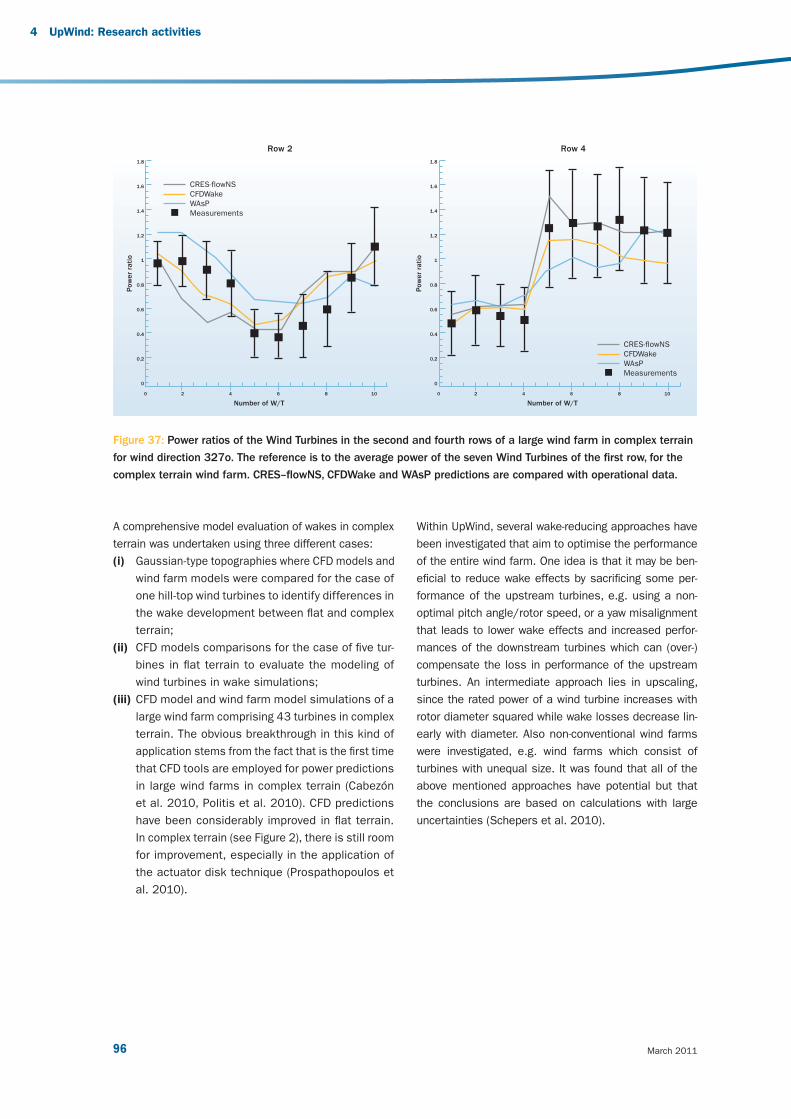
March 201196
A comprehensive model evaluation of wakes in complex
terrain was undertaken using three different cases:
(i) Gaussian-type topographies where CFD models and
wind farm models were compared for the case of
one hill-top wind turbines to identify differences in
the wake development between fl at and complex
terrain;
(ii) CFD models comparisons for the case of fi ve tur-
bines in fl at terrain to evaluate the modeling of
wind turbines in wake simulations;
(iii) CFD model and wind farm model simulations of a
large wind farm comprising 43 turbines in complex
terrain. The obvious breakthrough in this kind of
application stems from the fact that is the fi rst time
that CFD tools are employed for power predictions
in large wind farms in complex terrain (Cabezón
et al. 2010, Politis et al. 2010). CFD predictions
have been considerably improved in fl at terrain.
In complex terrain (see Figure 2), there is still room
for improvement, especially in the application of
the actuator disk technique (Prospathopoulos et
al. 2010).
Within UpWind, several wake-reducing approaches have
been investigated that aim to optimise the performance
of the entire wind farm. One idea is that it may be ben-
efi cial to reduce wake effects by sacrifi cing some per-
formance of the upstream turbines, e.g. using a non-
optimal pitch angle/rotor speed, or a yaw misalignment
that leads to lower wake effects and increased perfor-
mances of the downstream turbines which can (over-)
compensate the loss in performance of the upstream
turbines. An intermediate approach lies in upscaling,
since the rated power of a wind turbine increases with
rotor diameter squared while wake losses decrease lin-
early with diameter. Also non-conventional wind farms
were investigated, e.g. wind farms which consist of
turbines with unequal size. It was found that all of the
above mentioned approaches have potential but that
the conclusions are based on calculations with large
uncertainties (Schepers et al. 2010).
Figure 37: Power ratios of the Wind Turbines in the second and fourth rows of a large wind farm in complex terrain
for wind direction 327o. The reference is to the average power of the seven Wind Turbines of the fi rst row, for the
complex terrain wind farm. CRES–fl owNS, CFDWake and WAsP predictions are compared with operational data.
Number of W/T Number of W/T
Pow
er
rati
o
0 2 4 6 8 10
1.8
1.6
1.4
1.2
1
0.8
0.6
0.4
0.2
0
1.8
1.6
1.4
1.2
1
0.8
0.6
0.4
0.2
0
CRES-flowNS
CFDWake
WAsP
Measurements
Row 2 Row 4
Pow
er
rati
o
CRES-flowNS
CFDWake
WAsP
Measurements
0 2 4 6 8 10
4 UpWind: Research activities
v3_21895_UpWind Report_AttentionGraphDisparaissent.indd 96v3_21895_UpWind Report_AttentionGraphDisparaissent.indd 96 2/03/11 15:162/03/11 15:16

97 Design limits and solutions for very large wind turbines
References
[1] Barthelmie R.J., Pryor S.C., Frandsen S.T.,
Hansen K., Schepers J.G., Rados K., Schlez W.,
Neubert A., Jensen L.E., Neckelmann S. (2010)
Quantifying the impact of wind turbine wakes on
power output at offshore wind farms. Journal of
Atmospheric and Oceanic Technology 27:1302-
1317.
[2] Cabezón D., Hansen K., Barthelmie R.J. (2010)
Analysis and validation of CFD wind farm
models in complex terrain. Effects induced
by topography and wind turbines EWEC 2010
scientifi c proceedings, Warsaw, Poland, April
2010, p 7.
[3] Frandsen S., Barthelmie R.J., Jorgensen H.E.,
Rathmann O., Badger J., Hansen K., Ott S.,
Rethore P., Larsen S.E., Jensen L. (2009) The
making of a second-generation wind farm
effi ciency model-complex. Wind Energy 12:431-
444.
[4] Hansen K.H., Barthelmie R.J., Jensen L.E.,
Sommer A. (2010) The impact of turbulence
intensity and atmospheric stability on power
defi cits due to wind turbine wakes at Horns Rev
wind farm. Wind Energy Submitted 8 September
2010. WE-10-0149.
[5] Politis E., Prospathopoulos J., Cabezón D.,
Hansen K., Chaviaropoulos P., Barthelmie R.
(2010) Modeling wake effects in large wind farms
in complex terrain: the problem, the methods and
the issues. Wind Energy (WE-10-0103, submitted
2 July 2010).
[6] Prospathopoulos J.M., Politis E.S., Chaviaropoulos
P.K., Rados K.G., Schepers J.G., Cabezón D.,
Hansen K.S., Barthelmie R.J. (2010 ) CFD
Modeling of Wind Farms in Flat and Complex
Terrain. In: van Kuik G (ed) Proceedings of
the 2010 European Wind Energy Conference &
Exhibition, Warsaw, 20-23 April 2010, p 23-27.
[7] Rathmann O., Frandsen S.T., Barthelmie R.J.
(2007) Wake modeling for intermediate and large
wind farms. European Wind Energy Conference
and Exhibition, Milan, May 2007, p 8.
[8] Schepers G., Barthelmie R.J., Politis E.S.
(2010) Wake reducing concepts. Upwind WP8
Deliverable 8.5, ECN, Petten, p 30.
[9] Schlez W., Neubert A. (2009) New developments
in large wind farm modeling European Wind
Energy Conference, Marseille, p 8.
Typical wind farm layout optimisations operate by using
the energy yield as a target function. While leading to
layouts with maximum energy yield, this can be less than
optimal for the project economics, due to increased tur-
bine loading and associated cost. To optimise a layout
for overall cost including loading, three new key concepts
have been implemented. This allows us to optimise the
layout of a large wind farm with respect to an economic
target function, reduce the turbine loads and vary turbine
types to fi nd the most economic layout.
v3_21895_UpWind Report_AttentionGraphDisparaissent.indd 97v3_21895_UpWind Report_AttentionGraphDisparaissent.indd 97 2/03/11 15:162/03/11 15:16
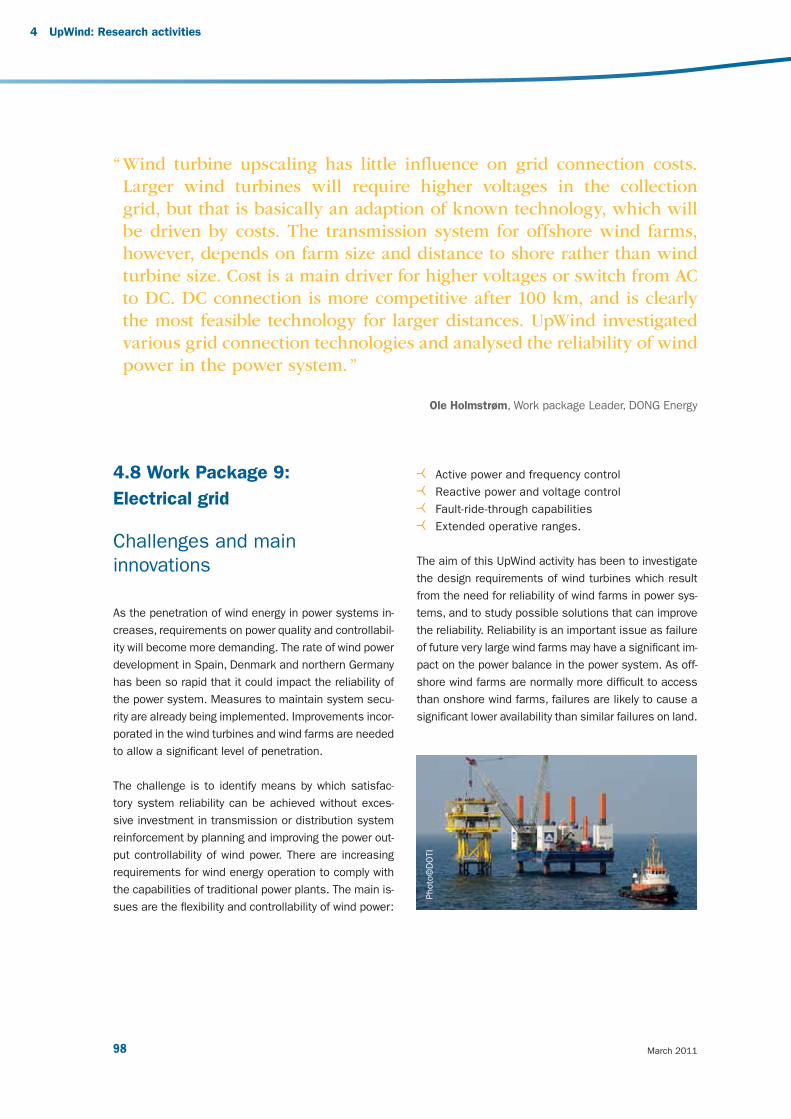
March 201198
4 UpWind: Research activities
4.8 Work Package 9:
Electrical grid
Challenges and main
innovations
As the penetration of wind energy in power systems in-
creases, requirements on power quality and controllabil-
ity will become more demanding. The rate of wind power
development in Spain, Denmark and northern Germany
has been so rapid that it could impact the reliability of
the power system. Measures to maintain system secu-
rity are already being implemented. Improvements incor-
porated in the wind turbines and wind farms are needed
to allow a signifi cant level of penetration.
The challenge is to identify means by which satisfac-
tory system reliability can be achieved without exces-
sive investment in transmission or distribution system
reinforcement by planning and improving the power out-
put controllability of wind power. There are increasing
requirements for wind energy operation to comply with
the capabilities of traditional power plants. The main is-
sues are the fl exibility and controllability of wind power:
Active power and frequency control
Reactive power and voltage control
Fault-ride-through capabilities
Extended operative ranges.
The aim of this UpWind activity has been to investigate
the design requirements of wind turbines which result
from the need for reliability of wind farms in power sys-
tems, and to study possible solutions that can improve
the reliability. Reliability is an important issue as failure
of future very large wind farms may have a signifi cant im-
pact on the power balance in the power system. As off-
shore wind farms are normally more diffi cult to access
than onshore wind farms, failures are likely to cause a
signifi cant lower availability than similar failures on land.
“ Wind turbine upscaling has little infl uence on grid connection costs.
Larger wind turbines will require higher voltages in the collection
grid, but that is basically an adaption of known technology, which will
be driven by costs. The transmission system for offshore wind farms,
however, depends on farm size and distance to shore rather than wind
turbine size. Cost is a main driver for higher voltages or switch from AC
to DC. DC connection is more competitive after 100 km, and is clearly
the most feasible technology for larger distances. UpWind investigated
various grid connection technologies and analysed the reliability of wind
power in the power system. ”
Ole Holmstrøm, Work package Leader, DONG Energy
Photo
©D
OTI
v3_21895_UpWind Report_AttentionGraphDisparaissent.indd 98v3_21895_UpWind Report_AttentionGraphDisparaissent.indd 98 2/03/11 15:162/03/11 15:16

99 Design limits and solutions for very large wind turbines
UpWind investigates operational as well as statistical
aspects of wind farm reliability with a focus on offshore
wind farms. Operational aspects include grid code re-
quirements, extreme wind conditions and specifi c wind
farm control options. The statistical aspects will be cov-
ered by the development of a database and by statisti-
cal modeling.
UpWind considers future large wind turbines turbines
of 5, 10 and 20 MW in very large offshore wind farms
of hundreds of MW. Signifi cant upscaling will have an
impact on electrical design and may have signifi cant
infl uence on reliability and availability. Upscaling trends
for cost modeling and technical and economical barri-
ers in relation to electrical design of the wind turbine
as well as the design of large offshore wind farms are
investigated.
Results
The UpWind activities in this fi eld are purely analytical
and focus on the main subjects of reliability modeling
and design criteria of future large wind turbines and
on the subject of improved grid integration. To a large
degree, the results are provided as results of modeling
and simulation.
Wind farm reliability
Power producing units can be considered in two re-
spects: the availability of the individual wind farm
itself and the impact on the reliability on the overall
electrical power system.
The initial problem to be solved is to provide adequate
general models and accurate data for the reliabil-
ity and risk assessments of wind turbines and wind
farms. These models are essential to enable compari-
son of different electrical-design and grid-connection
options.
Figure 38: Summary of grid integration requirements for wind turbines
Operational Requirements Technical Developments
Active Power Regulation
Grid integration Requirements
Grid-Operators
WT-Manufacturer
110%
P [
MW
] adjustablepower
gradient
t [min]
P/PN
0%
Fault-Ride-Through-Options Reactive Power regulation Extended Operative Ranges
-Q
- 0,9 + 0,9 U/Ux
+20%x
-20%x
57HzGrid-fault with FRT
without FRT
time
pow
er
P/P
=50Hz
43Hz+Q
P
v3_21895_UpWind Report_AttentionGraphDisparaissent.indd 99v3_21895_UpWind Report_AttentionGraphDisparaissent.indd 99 2/03/11 15:162/03/11 15:16

March 2011100
A survey of existing large offshore wind farms was per-
formed considering grid events, electrical construc-
tion and protection. The results and conclusion show
that specifi c wind farm component data is diffi cult to
obtain due to restricted access to data and due to
lack of statistics from offshore installations. The reli-
ability database considering electrical components in
wind farms was derived from data for onshore instal-
lations.
This served as the basis for the subsequent reliabil-
ity model of wind turbines and wind farms. These
were developed in different software tools: a general
commercial reliability software and ECN simulation
programme EeFarm. The models focus on the effect
the electrical design has on the reliability of large off-
shore wind farms considering the characteristics of
the wind. The developed reliability models are used in
the evaluation of upscaling.
Extreme wind conditions infl uence the reliability when
the wind speed drops fast or increases above the cut-
out wind speed. This is particularly important if sev-
eral large wind farms are geographically close. Models
are developed which can quantify the probability of
these events in terms of probability and amount of
lost generation and used to study the infl uence of con-
trol system modifi cations, aiming at less abrupt cut-
out of large-scale wind power generation. The analysis
is based on re-analysis data for wind speeds from
Max Planck Institute and from measurements from
Danish wind farms.
Power system requirements
The overall power system requirements are refl ected
in the grid codes. In this context it is important to pre-
dict what can be the future requirements of the trans-
mission system operators in order to integrate an in-
creased amount of wind power in the system. These
requirements have to be compared to the capabilities
of the wind turbine technology available today and in
the future. A state-of-the-art review of grid codes and
a corresponding survey on wind turbine performance
has been carried out, pinpointing the relevant require-
ments and design criteria in relation to operative rang-
es, active and reactive power control, and fault-ride-
through. The review of grid codes shows important
differences is the requirements across Europe. This
results in gross ineffi ciencies for manufacturers and
developers. This issue is now being addressed by the
European Wind Energy Association, which states that
there is an increasing need to develop a harmonised
set of grid code requirements due to the increasing
penetration of wind power.
The survey of the existing wind turbine technology
reveals that today’s wind turbine technology is capa-
ble of fulfi lling the current grid code requirements for
wind generation. This enables manufacturers to offer
wind power plant solutions tailored to the different
operational and connection requirements of different
grids. It has also been found, however, that system
operators often are not able to take full advantage of
the capabilities already available by wind turbine and
wind farm technology due to the lack of operational
aggregated control systems for wind power plants.
4 UpWind: Research activities
v3_21895_UpWind Report_AttentionGraphDisparaissent.indd 100v3_21895_UpWind Report_AttentionGraphDisparaissent.indd 100 2/03/11 15:162/03/11 15:16

101 Design limits and solutions for very large wind turbines
The analysis of small island grids give valuable in-
formation about systems with high wind penetration
pinpointing technical limits and measures that can
increase the wind capacity. The results can be used
to evaluate larger systems. First of all, constraints im-
posed by the conventional generators and security of
operation considerations result in signifi cant and fre-
quent wind power curtailments. In addition, small is-
land grids with high penetration of wind power depend
more on the reliability of the wind energy than corre-
sponding large interconnected systems. For this rea-
son, island systems are used for modeling and simu-
lations in order to investigate specifi c requirements
needed for wind turbines operating in such systems,
along with power and frequency control capabilities, to
fully exploit the high wind potential available.
Wind farm electrical design and control
The impact of various electrical and control concepts
of wind farms on reliability are investigated. The elec-
trical designs need to comply with relevant grid codes
and maximise reliability, observing reasonable cost
constraints. Different designs of electrical systems
for wind farms are evaluated with respect to the new
design criteria from grid codes and their ability to
participate in power control, including automatic fre-
quency and voltage control. This is done for island
(non-interconnected) systems as well as for large in-
terconnected power systems.
As for the non-interconnected power systems, the
response of different electrical confi gurations of
wind turbines during transient events in the grid is
investigated. The fault-ride-through capability of wind
turbines is crucial for the secure operation of non-
interconnected power systems. Power system inertia,
protection relays settings, voltage and frequency sta-
bility have to be carefully analysed before the pen-
etration margin levels are expanded. Due to reduced
power system inertia under high wind power penetra-
tion, the issue of frequency control provided by mod-
ern wind turbine technology is crucial. Additional con-
trol methods developed in wind turbines, like droop,
inertia and combined control, provide the capability
to support the system frequency during events that
affect the power balance. Therefore, penetration lev-
els beyond the limit of 30% (often applied to isolated
power systems) can be further expanded provided
that sophisticated frequency control services are im-
plemented in modern wind turbine technology.
The impact on interconnected power systems of large
wind farms with different turbine technologies has
been investigated. The investigation focuses on fault-
ride-through, power control and voltage support con-
trol capabilities of different wind farm concepts. The
contribution to grid support has been assessed and
discussed by means of case studies and simulations
with the use of a generic transmission power system
model. Simulations showed that both variable speed
wind turbine concepts can help nearby connected stall
or active stall wind turbines to ride-through grid faults
and can enable them to partly comply with grid code
requirements, without any need to implement addi-
tional ride-through control strategy in the active stall
wind farm.
v3_21895_UpWind Report_AttentionGraphDisparaissent.indd 101v3_21895_UpWind Report_AttentionGraphDisparaissent.indd 101 2/03/11 15:162/03/11 15:16
March 2011102
Among the variety of additional aspects concerning
wind farms’ ability to participate in advanced voltage
control schemes, one study focus on optimised per-
formance for a coordinated control of a STATCOM and
an ULTC transformer used to achieve a better voltage
profi le in the whole grid in steady state and in contin-
gency situations. Further, the project has also shown
that by using the control abilities of the future wind tur-
bines and wind farms together with power electronic
compensators in a different and more intelligent man-
ner, new features regarding, for instance, the ability to
help suppress SSR and power system oscillations in
the network grid can be achieved, which are possibili-
ties not yet described in the grid codes.
The internal transmission system of the future larger
offshore wind farms considering new technologies
may impact system reliability. Studies are conducted
in order to investigate HVDC connections and electri-
cal concepts with respect to their impact on system
security and compliance with the new design criteria
and grid code requirements.
Upscaling
The upscaling of wind turbines and wind farms is in-
vestigated, focusing on trends for electrical design
criteria, technical barriers and grid connection costs
considering up to 20 MW wind turbines and large off-
shore wind farms 500-1,000 MW.
First step is evaluation of upscaling trends for wind farm
grid connection was made using the developed reliability
model and an up-to-date data base with component
parameters and investment costs. The results give
trends as to choice of voltage levels, AC or DC solutions
depending on wind turbine sizes, wind farm sizes and
distance to shore.
Design criteria for the electrical infrastructure of fu-
ture wind farms are analysed for both AC and DC solu-
tions. HVDC is further detailed and different types of
technologies used for HVDC. The operation, control
and protection system was detailed in collaboration
with HVDC manufacturers. Key components and risks
of such systems were identifi ed. Subsequently the
electrical infrastructure focusing solely on DC net-
works was investigated. AC/DC converters are key
components in a DC grid and different topologies are
evaluated presently. When it comes to offshore instal-
lations, the converter platform design has to be inno-
vated as to the function of the converter components
and for redundancy reasons. The need for standardi-
sation of components is pointed to be a major factor
for the deployment of future DC connections.
A study of wind turbines design aspects focuses on
the physical size and design. As wind turbines rated
power output increase, a main barrier short-term for
optimised design of an AC collection grid is the con-
nection voltage in wind turbines. The investigation fo-
cused on this concludes that the electrical equipment
(transformers and switchgear) already exists, so that
the main issue is to adapt it for offshore wind turbines
and to make it reliable and more cost effective.
4 UpWind: Research activities
v3_21895_UpWind Report_AttentionGraphDisparaissent.indd 102v3_21895_UpWind Report_AttentionGraphDisparaissent.indd 102 2/03/11 15:162/03/11 15:16

103 Design limits and solutions for very large wind turbines
v3_21895_UpWind Report_AttentionGraphDisparaissent.indd 103v3_21895_UpWind Report_AttentionGraphDisparaissent.indd 103 2/03/11 15:162/03/11 15:16

v3_21895_UpWind Report_AttentionGraphDisparaissent.indd 104v3_21895_UpWind Report_AttentionGraphDisparaissent.indd 104 2/03/11 15:162/03/11 15:16