unmanned aerial vehicle with fire extinguishing …
TRANSCRIPT

EML 4905 Senior Design Project
A B.S. THESIS PREPARED IN PARTIAL FULFILLMENT OF THE
REQUIREMENT FOR THE DEGREE OF BACHELOR OF SCIENCE
IN MECHANICAL ENGINEERING
UNMANNED AERIAL VEHICLE WITH FIRE
EXTINGUISHING GRENADE RELEASE AND
INSPECTION SYSTEM
25% Report
Cesar Beltran Miriam Carolina Freitas
Alex Moribe
Advisor: Professor Igor Tsukanov
April 10, 2013
This B.S. thesis is written in partial fulfillment of the requirements in EML 4905. The contents represent the opinion of the authors and not
the Department of Mechanical and Materials Engineering.

P a g e | 2
Ethics Statement and Signatures The work submitted in this B.S. thesis is solely prepared by a team consisting of Miriam Carolina Freitas, Cesar Beltran and Alex Moribe and it is original. Excerpts from others’ work have been clearly identified, their work acknowledged within the text and listed in the list of references. All of the engineering drawings, computer programs, formulations, design work, prototype development and testing reported in this document are also original and prepared by the same team of students.
Miriam Carolina Freitas Team Leader
Cesar Beltran Team Member
Alex Moribe Team Member
Professor Igor Tsukanov
Faculty Advisor

P a g e | 3
Table of Contents Ethics Statement and Signatures ......................................................................................... 2
Table of Contents ................................................................................................................ 3
List of Figures ..................................................................................................................... 5
List of Tables ...................................................................................................................... 6
Abstract ............................................................................................................................... 7
1. Introduction ................................................................................................................. 8
1.1 Problem Statement ............................................................................................... 8
1.2 Motivation ............................................................................................................ 9
1.3 Literature Survey .................................................................................................... 11
1.3.1 Review History of Remote Control Vehicles .................................................. 11
1.3.2 Sensors and Software in UAVs........................................................................ 11
1.3.3 Firefighting Systems ................................................................................... 12
1.3.4 Regulations ...................................................................................................... 13
1.4 Discussion ............................................................................................................... 14
2. Project Formulation .................................................................................................. 15
2.1 Overview ............................................................................................................ 15
2.2 Project Objectives .............................................................................................. 15
2.3 Design Specifications ......................................................................................... 15
2.4 Constraints and Other Considerations ................................................................ 17
3. Design Alternatives ................................................................................................... 19
3.1 Overview of Conceptual Designs Developed ......................................................... 19
3.2 Design Alternative 1 ............................................................................................... 19
3.3 Design Alternative 2 ............................................................................................... 20
3.4 Design Alternative 3 ............................................................................................... 21
3.5 Proposed Design ..................................................................................................... 22
4. Project Management ..................................................................................................... 25
4.1 Overview ................................................................................................................. 25
4.2 Organization of Work and Timeline ...................................................................... 25
4.3 Breakdown of Responsibilities among Team Members ........................................ 26
5. Engineering Design and Analysis ............................................................................. 28
5.1 Major Components.................................................................................................. 28
5.1.1 Fire Ball Extinguish Grenade........................................................................... 28
5.1.2 Frame ............................................................................................................... 30
5.1.3 Motors .............................................................................................................. 31
5.1.4 Motor Controller and Flight Controller ........................................................... 32
5.1.5 Battery .............................................................................................................. 34
5.1.6 First Person View Camera ............................................................................... 35
5.1.7 GPS Flight Control System .............................................................................. 36
5.1.8 Ardu-Pilot ........................................................................................................ 36
5.1.9 Release Mechanism Platform .......................................................................... 37
5.1.10 Rails ............................................................................................................... 38
5.1.11 Servo Motor ................................................................................................... 38
5.2 Structural Design ................................................................................................ 38

P a g e | 4
5.2.1 Ease of Access to Load the Fire Extinguishing Grenade ................................. 39
5.2.2 Light and Resistant Materials .......................................................................... 39
5.2.3 Resistance to high temperatures....................................................................... 39
5.2.4 The design cannot interfere with the aerodynamics or stability of the quad ... 39
5.3 Analytical Analysis ................................................................................................. 40
5.3.1 Problem understanding .................................................................................... 40
5.3.2 Mathematical Model ........................................................................................ 40
5.3.3 Computational Methods ................................................................................... 41
5.3.4 Force Analysis ................................................................................................. 41
5.3.5 Shear analysis................................................................................................... 41
5.3.6 Thermal analysis .............................................................................................. 42
5.3 Cost Analysis...................................................................................................... 42
5.3.1 Design cost ....................................................................................................... 42
5.3.2 Report and Presentation Cost ........................................................................... 43
6. Prototype Construction ............................................................................................. 44
6.1 Prototype System Description................................................................................. 44
6.2 Prototype Cost Analysis .......................................................................................... 44
7. Testing and Evaluation ............................................................................................. 47
7.1Vehicle Performance Test ........................................................................................ 47
7.2 Release Mechanism Performance Test ................................................................... 47
7.3 Overall System Performance Test .......................................................................... 48
8. References ..................................................................................................................... 49
9. Appendices ................................................................................................................ 52
9.1 Appendix A: Properties of G-10 from MatWeb ..................................................... 52

P a g e | 5
List of Figures Figure 1: Quadcopter Model ........................................................................................... 16
Figure 2: Fire Extinguishing Grenade [10] .................................................................... 17
Figure 3: Design Alternative 1 ........................................................................................ 20
Figure 4: Design Alternative 2 ........................................................................................ 21
Figure 5: Design Alternative 3 ........................................................................................ 22
Figure 6: Top view of the UAV ........................................................................................ 23
Figure 7: Back View of the UAV ...................................................................................... 23
Figure 8: Side View of the UAV ....................................................................................... 24
Figure 9: Bottom View of the UAV ................................................................................. 24
Figure 10: Fire Extinguishing Grenade ............................................................................. 29
Figure 11: Motor ............................................................................................................... 32
Figure 12: Flight Controller .............................................................................................. 33
Figure 13: Motor Controller.............................................................................................. 33
Figure 14: Zippy Battery ................................................................................................... 34
Figure 15: First Person View Camera and Goggles.......................................................... 35
Figure 16: GPS .................................................................................................................. 36
Figure 17: ArduPilot ......................................................................................................... 37
Figure 18: Release Mechanism Platform .......................................................................... 37
Figure 19: Rails ................................................................................................................. 38

P a g e | 6
List of Tables Table 1: Timeline ............................................................................................................. 26
Table 2: Breakdown of Responsibilities ........................................................................ 27
Table 3: Specifications of the Fire Extinguishing Grenade .............................................. 29
Table 4: Specifications of the Frame of the Quadcopter .................................................. 30
Table 5: Specifications of the Motor ................................................................................ 32
Table 6: Specifications of Motor Controller and Flight Controller .................................. 34
Table 7: Specifications of the Battery ............................................................................... 35
Table 8: Design Cost ......................................................................................................... 43
Table 10: Report and Presentation Cost ............................................................................ 43
Table 9: Prototype Cost .................................................................................................... 46
P a g e | 7
Abstract
The ignition of certain materials that combust to create a fire is something
that most of the times occurs without being wanted. The damages that a fire causes
are proportional to the size of the fire. Sometimes, nothing happens to property and
living beings, but other times, the emotional and economic losses are too great to
afford to keep having fires that are difficult to control, and eventually extinguish.
For that reason, the intention of this design project is to improve the ways in
which fires are prevented and extinguished. UAVs are apparatuses that have
become popular in recent years thanks to not only their many capabilities to
program, but also that a human being does not need to be on board in order to
control it. Hence, this team decided to use them in an innovative and inventive
manner to create a mechanism to release a fire extinguishing grenade in the desired
location that will prevent fires or directly extinguish them.

P a g e | 8
1. Introduction
1.1 Problem Statement
Currently, there is a lack of unmanned aerial vehicles that are being used
with the purpose of extinguish a fire or help prevent one. An unmanned aerial
vehicle (UAV) is an aircraft without a human pilot on board. Its flight can be
controlled autonomously by computers in the vehicle, or by remote control under
the direct command of a human. In the United States and the rest of the world, most
of the UAVs in existence are being used for defense purposes.
Fires that occur in homes and nonresidential buildings as well as fires in wild
lands cause plenty of health issues; including death to humans and animals, in
addition to great economic losses in structures, equipment and vegetation.
Furthermore, the first response teams, such as firefighters, are exposing their lives
to great risks in order to extinguish a fire.
In addition to those huge problems, there is another one that does not cause
so many struggles, but it does have a negative effect when a fire occurs. One of the
most popular ways to extinguish fires is to spray water in the area affected by the
flames. The water can be delivered via hose using a pressurized fire hydrant, fire
sprinkler system, pumped from water sources, such as lakes, rivers or tanker trucks,
or dropped from aircrafts in the case of wild land fires. These techniques result
effective in extinguishing the fire; however, the damages that they cause to large
structures and its contents once the fire is extinguished, generally, are great. The
main disadvantage of spraying water in the area of the fire is that water can damage
the interior of the building. Especially in office buildings, where electronic
equipment and important documents exist in abundance, the contents of the
building are in great danger even if the fire is suppressed in a proper manner.
Also, the prevention of wildfires entails creating conscience among the
population living near forests and large spaces of vegetation. Letting the residents
know that they are the ones that can have the greatest impact in regards to starting
a fire; therefore, they are the ones in charge of preventing them. If awareness is not

P a g e | 9
raised successfully, there are still chances that fires can occur. Here is where our
team plays a great role by generating new ways of preventing wildfires.
In order to help those that risk their life when a fire takes place, the living
beings that can be potentially harmed and their surroundings, such as edifications
and forests, to preserve the goods inside a building once a fire occurs, and to help
avoid fires in open spaces, this team decided to focus this senior design project in
the development of an UAV that is going to prevent fires and also assist in
extinguishing them.
1.2 Motivation
The main reason why this team decided to build an UAV and integrate a fire
extinguishing ball release mechanism is because of all the advantages that UAVs
provide. Starting with the fact that UAVs do not need a pilot on board, they also can
get access to places in which life can be in danger if entered. Another reason to use
an UAV for this particular project is that it can be programmed to perform any
mission desired, without having human error on board. Of course, it has to be taken
into account that if any of the systems fail, the UAV will be in great risk of crashing,
but those probabilities are too small in comparison to the probabilities of having a
successful mission.
On the other hand, according to the U.S. Fire Administration National Fire
Incident Reporting, in the year 2011, there were 364,500 residential building fires.
A residential building is defined as a structure in which people live. Those fires
caused 2,450 deaths, 13,900 injuries and more than $6.6 billion in losses. On the
side of nonresidential buildings, they are defined as public or private enclosed
structures in which businesses, educational facilities, underground buildings,
hospitals and subway terminals are included. In the year 2011, there were 85,400
fires in nonresidential buildings in the U.S., causing 80 deaths, 1,100 injuries and
more than $2.4 billion in losses.
A wildfire is defined as the ignition and burning of large extensions of vegetation
in a wilderness area. Wildfires take place when the components of a fire triangle

P a g e | 10
come together in a vulnerable and sometimes predisposed area. These components
cause a fire when an ignition source is brought into contact with a combustible
material, such as trees and dry leaves, that are exposed to enough heat and has a
satisfactory supply of oxygen from the ambient air. A wildfire can be caused by
natural events, such as spontaneous combustion, lightning, sparks from rock falls
and volcanic eruptions; and can also be caused by human activities, such as,
discarded cigarettes, discarded glass and plastic (magnifying the rays and heat of
the sun), sparks from equipment, and power line arcs [3].
By the same token, in 2012, wildfires were responsible for burning more than
9.3 million acres in the United States, causing more than $450 million in property
damages, putting at risk around $136 billion in properties and generated more than
$270 million in fire suppression costs.
Regarding the ways in which fires are extinguished, lately two new
techniques were introduced to the market. The first one uses a fire extinguishing
ball that needs to be thrown in the location of the fire and once it is in contact with
the fire, it self-activates within 3 seconds and releases fire extinguishing chemicals
that work effectively in a room with a volume of approximately 9 m3. The second
technique consists of a similar method. It is called DSPA-5. It requires throwing the
device with fire extinguishing agents inside the room, and someone has to pull a
trigger to activate it. Presently, both devices are put in the location of the fire by a
human. This puts the person in charge of this task in huge danger, since the person
has to be very close to the fire.
Another important thing to keep in mind is that by the year 2030, Unmanned
Aerial Systems will be allowed by the Federal Aviation Administration (FAA) to
operate in the National Airspace system and provide a wide range of services.
As seen by all the facts described before, fires are causing plenty of human and
monetary losses in this country; therefore, this team decided to change the
application of the regular UAVs being constructed for military purposes, and build
and design an UAV that can help a great amount of people being affected by flames

P a g e | 11
and smoke, that most of the times cannot be prevented or well controlled in an
effective and timely manner.
1.3 Literature Survey
1.3.1 Review History of Remote Control Vehicles
The beginning of the development of remote controlled devices started with
the invention of the radio, back in the 1880’s, when Nikola Tesla invented the
induction coil, a necessary device to send and receive radio waves. At first, these
radio signals were intended for communications purposes, but during World War I
the Germans started using remote control stations for manipulating tanks loaded
with explosives. Between 1914 and 1918, the development of various radio
controlled unmanned aircraft were intended to be used for military purposes;
however none of the prototypes was fully functional to be used during the war. This
also marked the beginning of the use of radio waves for commanding machines and
computers, such as power plants and satellites.
After the increasing development in computer technologies in the 1940’s, the
use of UAVs had opened new frontiers, mostly military purposes for reconnaissance
missions and also pilot trainings, but their civilian applications were moving slowly
along with research. One clear example is the incorporation of GPS technologies.
Since World War II, the preliminary research into general relativity led to the base
for our actual GPS technologies, this was called ground-based radio-navigation
systems. Although, it was not until the 1990’s that the US began incorporating this
technology into the UAVs of that period.
1.3.2 Sensors and Software in UAVs
With the culmination of the programmable digital computer in the 1940’s, the
idea of having a totally independent machine has been the subject of multiple
studies. While a fully independent machine was not developed, the components of
P a g e | 12
such devices could work independently according to the input signals they compute
from the surrounding areas, this signals vary from changes in:
- Altitude (altimeters)
- Acceleration (accelerometers)
- Temperature (thermocouples)
- Light (photo resistors)
Multiple lines of code can be used to control the most desired outcome after
reading the sensor; this is done through computer software that uploads the
necessary instructions for the UAV to follow.
The reason why sensors are important is because they are the main source of input
information for a machine to have its decisions based on. GPS, ultrasonic, thermal
sensors, cameras, are just a few of the different types of sensors that can be
incorporated into an UAV; speed for this input is important, but what matters most
is the code used in order to manipulate this information.
Technological advances in the performance of sensors were seen between
the 1950 and 1990, improving the response for their tasks, which were mainly
surveillance, bombing, and pilot training. It was not until the introduction of the GPS
in the 1990’s that UAVs took a major role in not only military but also civilian
objective.
In these last years, the U.S. is spending more than $50 billion annually in UAV
development and testing. This covers from drones to weather balloons, but
advances in UAVs for firefighting technology has not been put together yet.
1.3.3 Firefighting Systems
The different types of firefighting systems that are currently used in the market
are:
• Fire sprinkler systems: This system consists of a series of devices attached to
the roof of each floor of a building or home, and water is connected to them.
When the fire sprinkler detects smoke, it activates and releases water.

P a g e | 13
• Wet and dry chemical agents: This method to fight fires works by minimizing,
isolating, or reducing the fuel or heat. Reducing or isolating the oxygen or
inhibiting the chain reaction of the components. This method causes less
damage than water but some agents can be harmful after long term exposure.
• Gaseous agents: Leaving the wet chemical agents aside for practical reasons
like saving electronic devices in the affected area, dry chemical agents are the
best solution to firefighting. They are similar to the gaseous systems but in
most cases had been proved faster than other methods.
Extinguishing a fire is a dangerous task, especially if the place is not equipped
with any firefighting system and in most cases a firefighter needs to enter a building
if there are people inside. To avoid putting at risks more human lives, an aerial
firefighting gadget can be send inside the building that is in fire to place a gaseous
firefighting agent tool; for this purpose a quad copter works best because of its
stability capabilities. Few companies in the US already sell generators of gaseous
firefighting systems. They are small in size, portable, easily deployed and can cover
a substantial damaged area. By adapting a generator to an UAV equipped with a
front camera, one can easily enter a building in fire without risks, and the placing of
the generator will be more accurate.
1.3.4 Regulations
Similar to what has happened with incorporating new technologies into our
lives, UAVs are part of ethics discussions and companies that hold the technologies
to create such flying devices, and their components, are waiting to start profiting
from the results.
So far, the use of UAVs in the civilian sector is mainly for surveillance
purposes, which is one of the functions of drones, for military purposes, but there
are no limits for what they can be useful in research and governmental purposes. To
name a few, Vertical Profiles of Shortwave Atmospheric Heating Rates, Imaging
Spectroscopy, Topographic Mapping; and non-research, Coastal Patrol, Forest Fire

P a g e | 14
Damage Assessment, Forest Fire Mapping, Invasive Plant Assessment. Most of these
applications are in early developments and there is lack of regulations and
specifications for starting with new projects. These regulations concern the
following:
• Lack of airspace regulation that covers all types of UAV systems (encompassing
‘sense and avoid’)
• Affordability - price and customization issues
• Efforts to establish joint customer requirements
• Liability for civil operation
The lack of precise regulations has not stopped the enthusiasm of individuals
and known universities, to create or modify existing UAVs into what could possibly
be helpful in the future. The Swiss Federal Institute of Technology Zurich has a
department focused only in the development of intelligent aircraft. In there,
competitions are held often and individuals can share open source code for their
UAVs.
The development of UAVs must be accompanied by a high ethical sense and
preservation of privacy of everyone. This does not mean that research should be
stopped or restricted, just the opposite, it should be open to everyone to get more
contributions and increase the capabilities of any application. Until now, the
computing and programming part of the UAVs had been moving along side, which
means that the faster and more accurate technology becomes, better, more
interesting and helpful ideas for UAVs can be designed.
1.4 Discussion
The eradication of fires in a manner that no lives are lost, and that the cost of
extinguishing the flames is reduced to a minimum comes from prevention and
having a well educated population. Nonetheless, there are certain situations in
which fires occur in unexpected and fast ways; therefore, there have to be
competent and cost efficient methods in order to approach the extinguishing of the
flames and smoke without the losses that usually fires cause.

P a g e | 15
2. Project Formulation
2.1 Overview
Fires spread around the U.S. in an unpredictable way. Because of this, most of
the times it is hard for firefighting departments across the country to control them,
as well as eradicate the flames and smoke of the affected area in an inexpensive and
timely manner.
Knowing these facts, this team will design and build an UAV that will have
three purposes: fire prevention, firefighting and inspection. Fire prevention and
firefighting will be achieved through the ejection of a fire extinguishing ball or
grenade in the area in which the fire is taking place. Inspection will be accomplished
by installing cameras in the UAV.
2.2 Project Objectives
The purpose of this project is to build an UAV and attach to it a release
mechanism for the fire extinguishing ball. This mechanism will be entirely designed
and manufactured by the members of this team. The UAV is going to be built using
parts already in existence and this team is going to put them together in order to
construct a vehicle that is able to comply with all requirements to extinguish,
prevent and inspect a fire.
The UAV will be capable of delivering the grenade in an area that is hard to
approach by conventional methods or is more expensive to do it in other ways. Once
this system is up and running, a camera is going to be added to the vehicle. With
this, the second application takes place, which is inspection by live video recording
and pictures. In addition, the camera is also going to help in taking the vehicle to the
place desired by the controller.
2.3 Design Specifications
The requirements of the UAV are the following: pick up one fire extinguishing
grenade, drop it off in the area chosen by the operator, and have a camera that is
P a g e | 16
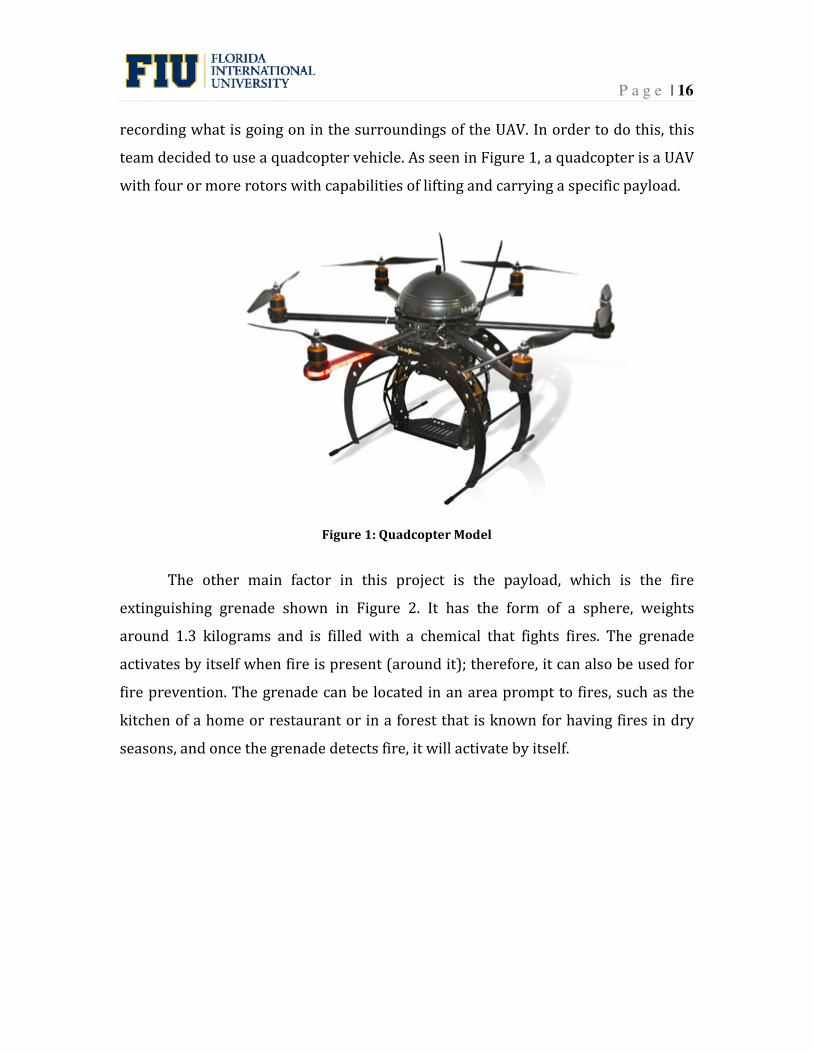
recording what is going on in the surroundings of the UAV. In order to do this, this
team decided to use a quadcopter vehicle. As seen in Figure 1, a quadcopter is a UAV
with four or more rotors with capabilities of lifting and carrying a specific payload.
Figure 1: Quadcopter Model
The other main factor in this project is the payload, which is the fire
extinguishing grenade shown in Figure 2. It has the form of a sphere, weights
around 1.3 kilograms and is filled with a chemical that fights fires. The grenade
activates by itself when fire is present (around it); therefore, it can also be used for
fire prevention. The grenade can be located in an area prompt to fires, such as the
kitchen of a home or restaurant or in a forest that is known for having fires in dry
seasons, and once the grenade detects fire, it will activate by itself.

P a g e | 17
Figure 2: Fire Extinguishing Grenade [10]
It is also worth noticing that another one of the most relevant requirements
of the multicopter is a GPS system. This will allow the operator to indicate the
location of the fire and the release place, and will also specify the exact location of
the UAV at all times. In addition with a ground station, the operator can have control
of the vehicle in case it goes out of range or the mission has been rearranged.
Furthermore, sensors of proximity and altitude will be incorporated to provide the
multicopter the ability to avoid a collision with other objects.
2.4 Constraints and Other Considerations
The first limitation faced by the team is the fact that the university does not
have the adequate facilities to test a UAV; therefore, designing the main components
of the quadcopter according to the exact needs of integration of the release
mechanism and placement of the camera was not a possibility.
Furthermore, one of the major constraints is the place in which the vehicle is
going to release the fire extinguishing grenade. If the grenade is going to be released
in an open space, such as a forest, the purpose of the grenade is for prevention. The
open space location cannot be on fire when the UAV arrives, because the flames
would melt the UAV. Another thing to keep in mind is that the grenade is more
effective when it releases its chemicals inside a room that has a volume of less than
9.5 m3; therefore, a perfect use of this grenade would be when the room of a house

P a g e | 18
or the room of a tall building is on fire. The way to access specific rooms in a
structure is through a window. To use the UAV to release the fire extinguishing
grenade, this window has to be open and the UAV will release the ball in a way that
will fall inside the desired room while it stays outside the area on fire, since the
vehicle is in danger of suffering great damages if it is too close to the flames. In this
situation, the window has to be open; otherwise the UAV will not have a way to
accomplish its goal.

P a g e | 19
3. Design Alternatives
3.1 Overview of Conceptual Designs Developed
Three major designs were considered in order to accomplish our goal, which
is release a fire extinguishing ball in a determined location, in addition to having a
camera in the vehicle that is going to video record what is going on and also take
pictures of its surroundings. These two main objectives of the quadcopter are what
defined the characteristics of each design that is going to be presented in the
following sections.
3.2 Design Alternative 1
This design has the purpose of dropping the fireball through a two door
opening at the bottom of the box. A box was chosen as a way of protecting the
fireball from the fire, so it does not activate before being located at the target. Servo
motors control the two doors simultaneously from a computer program that is
connected to the quadcopter through radio signal. The material of the mechanism is
aluminum, which has a light weight and is easy to manufacture. The disadvantage of
this design is the close distance to the fire the quadcopter has to get at the releasing
point, since not only the ball has to be protected from the fire during the flight but
also the motors and electronic components need to be isolated from high
temperatures. This design can be seen in Figure 3.

P a g e | 20
Figure 3: Design Alternative 1
3.3 Design Alternative 2
As a way of saving material for the mechanism, a cage design can be used for
holding the fireball while making the releasing process easier at the same time. Two
solid bars are placed at opposite sides of the bottom of the quad and are surrounded
by metallic strings for holding the fireball in place and are connected to controlled
locks at the bottom plate. The releasing process takes place when the bars are
unlocked making the bottom platform of the mechanism to fall along with the ball.
The disadvantage of this process is reloading the fireball. Since we want a system
that can do multiple trips if needed, having this type of procedure requires having
more than one bottom platform for holding the fireball in place, and putting the
parts together can take an approximated time of five minutes. This design can be
appreciated in Figure 4.

P a g e | 21
Figure 4: Design Alternative 2
3.4 Design Alternative 3
This design consists of having railing system connected to the bottom of the
platform that holds the fire extinguishing ball, and this will be the release
mechanism.
The cage design from the second alternative still stays attached to the
quadcopter and just the rails are added. The rails will serve to guide the fire
extingusihing ball to its target while at the same time keeps the quadcopter at a safe
distance from the flames. A servo motor controls the angle at which the railing
system is going to rotate. This will provide control over the velocity at which the fire
extinguishing grenade is released.
When the vehicle reaches the desired location for releasing the grenade, the
servo motor activates and lowers the railing system while at the same time it pushes
the fire extinguishing grenade from the back of the cage.

P a g e | 22
Figure 5: Design Alternative 3
3.5 Proposed Design
The chosen design for this senior project is alternative 3. After careful
consideration, the members of this team realized that this design will not only
provide safe release of the grenade, but also good support for the electronic
equipment necessary in order for the vehicle to perform all the tasks defined in the
objectives. In Figures 6, 7, 8 and 9 can be appreciated more views of the proposed
design.

P a g e | 23
Figure 6: Top view of the UAV
Figure 7: Back View of the UAV

P a g e | 24
Figure 8: Side View of the UAV
Figure 9: Bottom View of the UAV

P a g e | 25
4. Project Management
4.1 Overview
The organization of the tasks needed to complete in order to have a
successful project was made having in mind that commitment and efficiency were
the keys. Having two semesters to accomplish the goal set up for this project, careful
consideration was made choosing what were the main tasks needed to accomplish
by the end of the spring semester. Consequently, it was decided that by the end of
spring and beginning of summer the design of the release mechanism will be
complete. In the meantime, the parts to build the quadcopter were going to be
ordered and its construction would start as soon as all of them arrive, estimating
that would happen in by the middle of May.
4.2 Organization of Work and Timeline
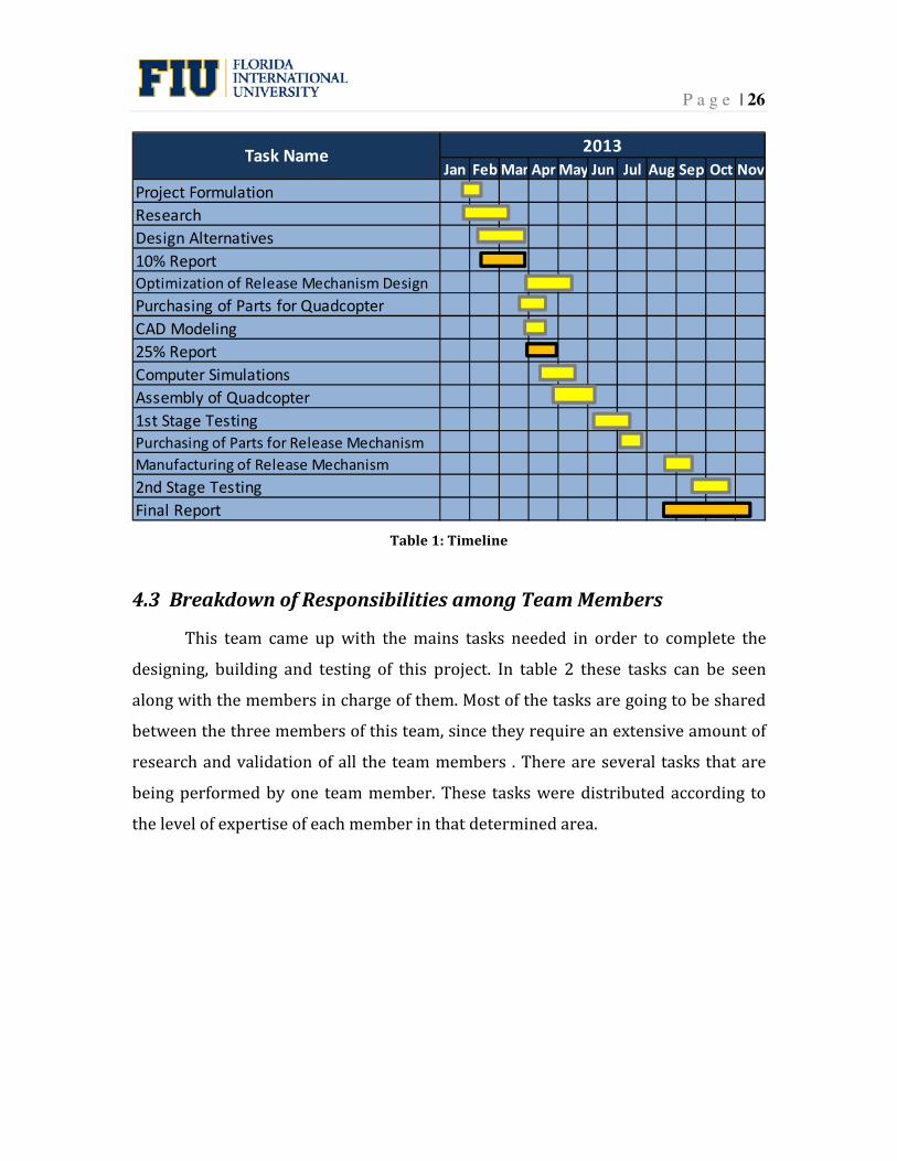
In Table 1 can be seen the timeline for this senior design project. Each stage
of the project is shown along with the time frame required in order to complete all
the tasks. In the table can also be seen what are the approximated dates in which
each task should be completed.
P a g e | 26
Jan Feb Mar Apr May Jun Jul Aug Sep Oct Nov
Project Formulation
Research
Design Alternatives
10% Report
Optimization of Release Mechanism Design
Purchasing of Parts for Quadcopter
CAD Modeling
25% Report
Computer Simulations
Assembly of Quadcopter
1st Stage Testing
Purchasing of Parts for Release Mechanism
Manufacturing of Release Mechanism
2nd Stage Testing
Final Report
Task Name2013
Table 1: Timeline
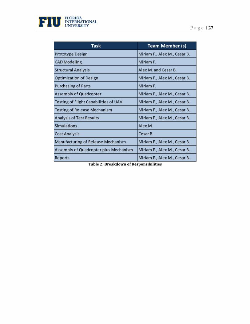
4.3 Breakdown of Responsibilities among Team Members
This team came up with the mains tasks needed in order to complete the
designing, building and testing of this project. In table 2 these tasks can be seen
along with the members in charge of them. Most of the tasks are going to be shared
between the three members of this team, since they require an extensive amount of
research and validation of all the team members . There are several tasks that are
being performed by one team member. These tasks were distributed according to
the level of expertise of each member in that determined area.
P a g e | 27
Task Team Member (s)
Prototype Design Miriam F., Alex M., Cesar B.
CAD Modeling Miriam F.
Structural Analysis Alex M. and Cesar B.
Optimization of Design Miriam F., Alex M., Cesar B.
Purchasing of Parts Miriam F.
Assembly of Quadcopter Miriam F., Alex M., Cesar B.
Testing of Flight Capabilities of UAV Miriam F., Alex M., Cesar B.
Testing of Release Mechanism Miriam F., Alex M., Cesar B.
Analysis of Test Results Miriam F., Alex M., Cesar B.
Simulations Alex M.
Cost Analysis Cesar B.
Manufacturing of Release Mechanism Miriam F., Alex M., Cesar B.
Assembly of Quadcopter plus Mechanism Miriam F., Alex M., Cesar B.
Reports Miriam F., Alex M., Cesar B.
Table 2: Breakdown of Responsibilities

P a g e | 28
5. Engineering Design and Analysis
5.1 Major Components
There are many important components that are part of the quadcopter
structure. Therefore, the UAV for fire extinguishing grenade release and inspection
could be examined as a set of individual components according to the function of
each system that conform a set. There are three main sets shown in the following
list:
1) Fire Ball Extinguish Grenade.
2) Quadcopter Componets: Frame, motors, motor controller and flight
controller, battery, first person view camera, GPS flight control system and
Ardu-Pilot.
3) Release Mechanism: Release mechanism platform, rails and servo motor.
5.1.1 Fire Ball Extinguish Grenade
This grenade is filled with an aerosol capable of extinguish fires using
nitrogen mixed with potassium. The aerosol compound contains 70% of nitrogen
and 30% of very fine particles of potassium. Using these two components, this
method of extinguishing fires is successful in fully developed and in early stages fire.
This grenade was designed to replace a Halon fire extinguisher, since its method of
operation is to cut off the oxygen supply of the area in which is used; therefore, it
could cause serious harm to person if used inside a closed room.
The physical characteristics of the fire extinguishing grenade can be
appreciated in Figure 1. This grenade has a solid material system that is filled with a
minimal amount of extinguishing compound. The compound acts directly on the
flame; hence, having an uninterrupted interaction with the burning surface once the
fire extinguishing chemicals are released. This device can be activated by thermal
reaction, electronically or manually. The grenade is going to eject the potassium
solid as aerosol in a 360 degrees direction and the total deployment time will be 40
seconds.

P a g e | 29
Figure 10: Fire Extinguishing Grenade
One of the advantages of this dispositive is that it keeps oxygen levels intact
in case humans are in close range when the grenade is activated. Another important
point is that it increases the safety of firefighting personal when they try to
extinguish a fire. The fire ball can extinguish 3 types of fires. One of them is type 1A,
which is fire that blazes fueled by solids such as wood, plastic, paper and cloth. The
second type is 5B fire class, which contains substances such as inflammable
material. The third type is C fire class, which is used for electrical parts where water
cannot be applied. The specifications of the fire extinguishing grenade are shown in
Table 3.
Table 3: Specifications of the Fire Extinguishing Grenade
Feature Value
Diameter (m) 0.145
Weight (Kg) 1.5
Volume of action (m3) 9.12
Activate Time (sec) 3 to 10
Useful life (years) 5
Extinguish classes 1A - 5B – C
Fire Extinguishing Agent Mono Ammonium Phosphate

P a g e | 30
5.1.2 Frame
The frame of the UAV is composed of three plates, two large main plates
joined by pins and one small plate of top of them. This allows a configuration of up
to 8 arms (or booms); however, this team decided to build a quadcopter, which has
a configuration of four arms. The four booms that hold the motors are placed at 90˚
with respect to each other.
The three plates are made of a material called G-10, which is a fiber glass
epoxy composite known for its high strength and resistance to high temperatures.
Its properties are available in Appendix A.
The diameter of the two main plates is 8.125”. These booms are secured to
the main plates by screws that are 1-1/8” long and they rest over two U blocks, one
behind the other. The second half of the U blocks is added to the top to clamp the
boom to the structure. Another main plate is installed on the top of the arms and the
whole structure is going to be held together by adding nuts to the screws. For better
support, screws of 3/8” in length are added around the main plates to help hold the
structure in place. The motor is mounted at the end of each boom over a flat surface
that is secured to the arm by two U supports and four 1-1/4” long screws. A small
plate is placed at the top of the two main plates and the electronics components are
located in this area, between the top small plate and the top main plate. All these
data can be better appreciated in Table 4.
Table 4: Specifications of the Frame of the Quadcopter
Feature Value
Main plates diameter (in) 8.125
Screws (in) 1-1/8
Outer Screws (in) 1-1/4
Support Plates Screws (in) 3/8
Tube length (in) 13
Material Carbon fiber
P a g e | 31
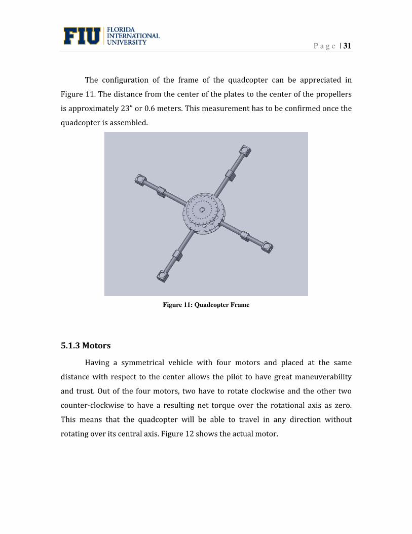
The configuration of the frame of the quadcopter can be appreciated in
Figure 11. The distance from the center of the plates to the center of the propellers
is approximately 23” or 0.6 meters. This measurement has to be confirmed once the
quadcopter is assembled.
Figure 11: Quadcopter Frame
5.1.3 Motors
Having a symmetrical vehicle with four motors and placed at the same
distance with respect to the center allows the pilot to have great maneuverability
and trust. Out of the four motors, two have to rotate clockwise and the other two
counter-clockwise to have a resulting net torque over the rotational axis as zero.
This means that the quadcopter will be able to travel in any direction without
rotating over its central axis. Figure 12 shows the actual motor.
P a g e | 32
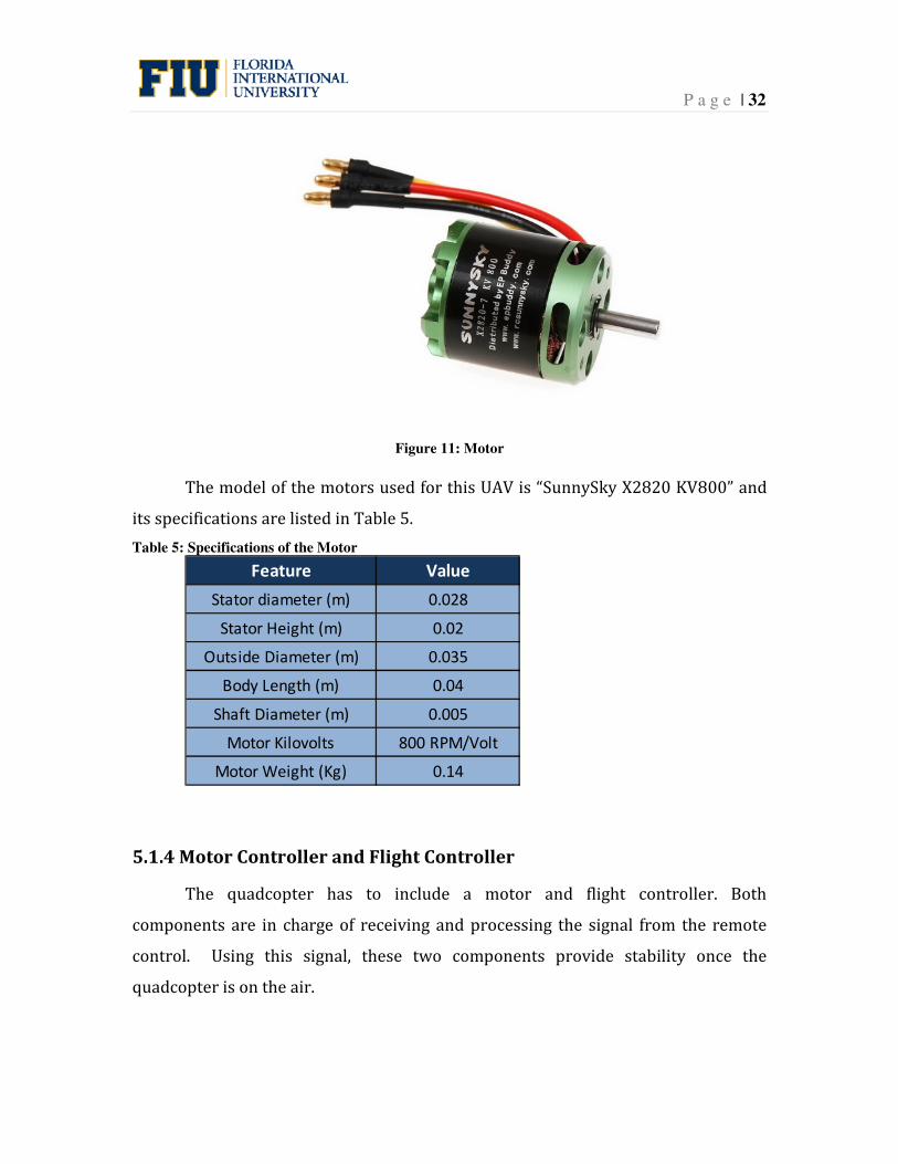
Figure 11: Motor
The model of the motors used for this UAV is “SunnySky X2820 KV800” and
its specifications are listed in Table 5.
Table 5: Specifications of the Motor
Feature Value
Stator diameter (m) 0.028
Stator Height (m) 0.02
Outside Diameter (m) 0.035
Body Length (m) 0.04
Shaft Diameter (m) 0.005
Motor Kilovolts 800 RPM/Volt
Motor Weight (Kg) 0.14
5.1.4 Motor Controller and Flight Controller
The quadcopter has to include a motor and flight controller. Both
components are in charge of receiving and processing the signal from the remote
control. Using this signal, these two components provide stability once the
quadcopter is on the air.

P a g e | 33
In case the vehicle suddenly loses balance, for a reason such as a wind
current, the motor controller (Figure 13) and the flight controller (Figure 14) have
the capability of resetting the quadopcter to its initial position and generate the final
decision to operate the motors in such way that they stabilize the vehicle.
Both devices are extremely relevant at the time of releasing the fire
extinguishing grenade, since they will provide the necessary stability in order for
the quadcopter not to crash with the structure or lose steadiness and crash with the
ground.
Figure 12: Flight Controller
Figure 13: Motor Controller
The specifications of the flight controller and the motor controller are shown in
Table 6.
P a g e | 34
Table 6: Specifications of Motor Controller and Flight Controller
Component Feature Value
Current (A) 40
Weight (Kg) 0.06
Voltage (V) 5
Current (A) 3
Weight (Kg) 0.0115
Motor Controller
Flight Controller
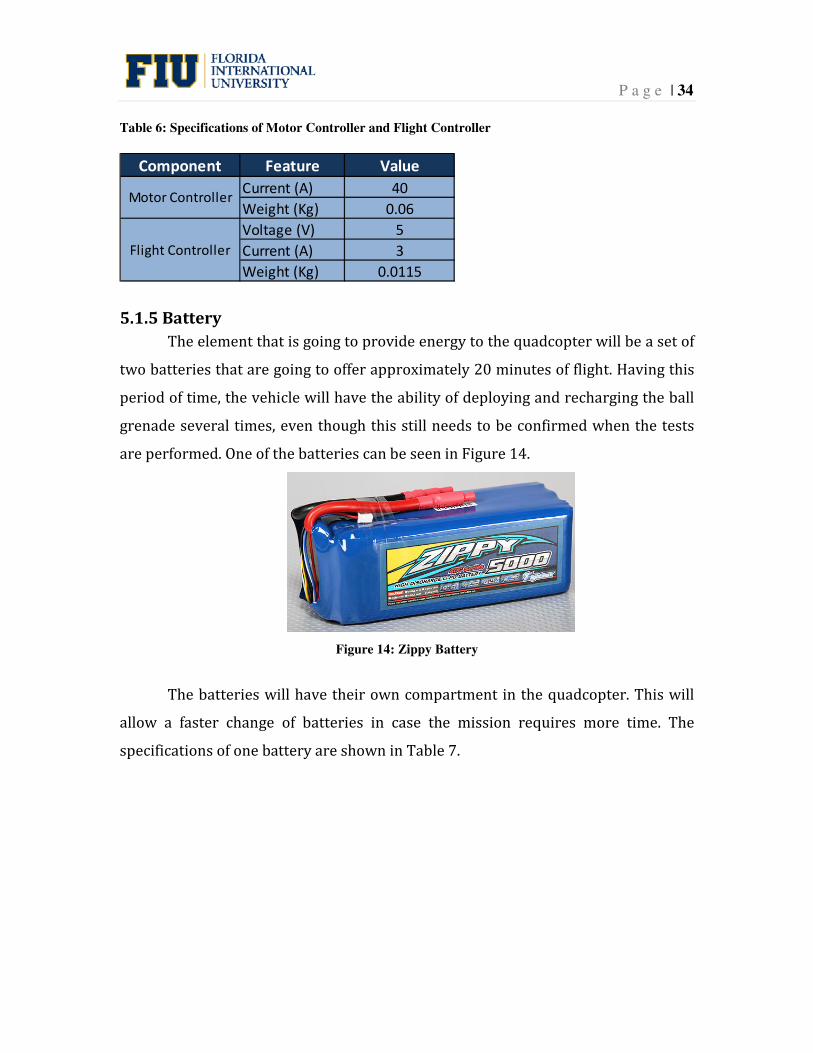
5.1.5 Battery
The element that is going to provide energy to the quadcopter will be a set of
two batteries that are going to offer approximately 20 minutes of flight. Having this
period of time, the vehicle will have the ability of deploying and recharging the ball
grenade several times, even though this still needs to be confirmed when the tests
are performed. One of the batteries can be seen in Figure 14.
Figure 14: Zippy Battery
The batteries will have their own compartment in the quadcopter. This will
allow a faster change of batteries in case the mission requires more time. The
specifications of one battery are shown in Table 7.
P a g e | 35
Table 7: Specifications of the Battery
Feature Value
Voltage (V) 22.2
Weight (kg) 0.834
Length (m) 0.156
height (m) 0.051
Width (m) 0.053
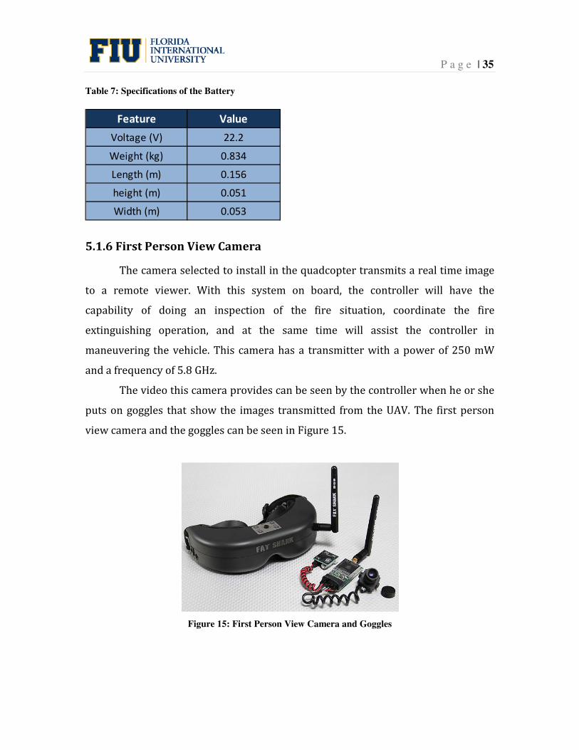
5.1.6 First Person View Camera
The camera selected to install in the quadcopter transmits a real time image
to a remote viewer. With this system on board, the controller will have the
capability of doing an inspection of the fire situation, coordinate the fire
extinguishing operation, and at the same time will assist the controller in
maneuvering the vehicle. This camera has a transmitter with a power of 250 mW
and a frequency of 5.8 GHz.
The video this camera provides can be seen by the controller when he or she
puts on goggles that show the images transmitted from the UAV. The first person
view camera and the goggles can be seen in Figure 15.
Figure 15: First Person View Camera and Goggles

P a g e | 36
5.1.7 GPS Flight Control System
This system can be used to convert this quadcopter in a fully autonomous
vehicle capable of performing programmed missions. However, in the vehicle, this
device will be used as a locator while the mission is being performed. This system
will work in conjunction an Ardupilot. This will provide refinement of the
movements and behavior of the quadcopter during flight. The GPS weight is 0.2 kg
and its frequency is 915 Mhz. The GPS can be seen in Figure 16.
Figure 16: GPS
5.1.8 Ardu-Pilot
ArduPilot is a software system based on the Arduino platform, which is an
open computing system (hardware). This software contributes to autonomous
stabilization and GPS navigation to allow the vehicle to accomplish missions without
human control. Another important function is that quadcopter will have
autonomous landing in case the pilot loses visibility of the vehicle. In Figure 17 the
Ardu-Pilot device can be seen.

P a g e | 37
Figure 17: ArduPilot
5.1.9 Release Mechanism Platform
According to the proposed design, the fire extinguishing grenade is going to
be held below the second main plate inside the release mechanism. One of the main
components of the release mechanism is the platform. This platform will hold the
grenade, plus it will have the columns attaching the release mechanism to the
quadcopter. The proposed design of the platform can be seen in Figure 18.
Figure 18: Release Mechanism Platform

P a g e | 38
The platform has to have a diameter bigger than 145 mm, which is the
diameter of the grenade. Since there have to be enough clearance for the columns
and to charge the grenade inside the mechanism, it was decided that the diameter of
the platform is 170 mm. The material has not been decided yet, even though using
carbon fiber is a strong possibility.
5.1.10 Rails
The rails in which the fire extinguishing grenade is going to roll will be
possible made of carbon fiber bars. They will have the shape of a cylinder and an
approximate diameter of 4mm and their length will be approximately 1 meter. In
Figure 19 the rails can be seen.
Figure 19: Rails
5.1.11 Servo Motor
In order to move the rails to the angle desired in order to release the
grenade, a servo motor will be used. The specifications of this servo motor are not
known yet, since this team is waiting to assemble the quadcopter and perform some
tests in order to decide what will be the best servo motor for our mechanism.
5.2 Structural Design
The main focus of this project is the mechanism to release the grenade;
therefore, the main factors taken into account to satisfy the requirements of the
release mechanism are: Ease of access to load the fire extinguishing grenade, light
and resistant materials, resistance to high temperatures and that the design cannot
P a g e | 39
interfere with the aerodynamics or stability of the vehicle. These factors are going to
be explained in the following sections.
5.2.1 Ease of Access to Load the Fire Extinguishing Grenade
Since the quadcopter will be used for emergency situations, it is required that
the person in control can mount the fireball into the quadcopter without much
work, also the reloading process has to be simple. A lock and load mechanism will
be implemented for this purpose.
5.2.2 Light and Resistant Materials
The use light and resistant materials in order to construct the quadcopter
and the release mechanism are of extreme importance, since it is necessary that the
copter moves fast to the objective and can also withstand the stresses that the load
carried can produce. The high reliability of the materials is also a main factor in the
decision making about what material should be used for the structural components
of the vehicle.
5.2.3 Resistance to high temperatures
Testing will be necessary to provide information about how close to the fire
the copter can get, since not only the frame of the release mechanism will be closer
to the flames, but also the electronics components of the quadcopter, such as
motors, cables, antenna, and camera, will be in a considerable short distance to the
high temperatures during the release process.
5.2.4 The design cannot interfere with the aerodynamics or stability of
the quad
Normally, a quadcopter has a weight distribution that contributes to stability.
An example of this is that heavier components, such as batteries and camera, will be
mounted in the center of the body. In this design, the release mechanism has an
extension that works as a slide to deliver the fireball as close as possible to the fire.
P a g e | 40
Even though the flight controls can adjust the motors to work accordingly to the
position of the quad, an abnormal weight distribution, like a heavy release
mechanism coming outside of the center of the body, will require one or more
motors to produce more thrust in order to maintain stability. Also, the motors need
to be isolated at the top and bottom, so thrust can be created in an effective manner;
therefore, the release mechanism has to have the most aerodynamic shape available
and weight as less as possible.
5.3 Analytical Analysis
5.3.1 Problem understanding
The first task when this project started was to define what type of loading
would be used in order to release it from the UAV. With the results obtained from
this investigation, the team created a guide to follow in order to accomplish the
goals established for this project. The first step was to understand the quadcopter
components and how they related to each other. Once the team knows exactly how
a UAV, the team will be capable of designing the release mechanism that will
transport the grenade with and release it with precision. The second step is to make
simulations about force, stress, strain and thermal analysis of the entire vehicle and
the proposed design for the release mechanism. Having this simulation in place, the
team will be able to choose the best configuration to deliver the grenade.
5.3.2 Mathematical Model
In order to identify the essential physical restriction of the release
mechanism design, the team will translate all the parameters into a mathematical
representation of the problem. The first stage is to calculate the thrust and the
efficiency of the vehicle. The second stage is to represent the release mechanism as
close as possible using CAD software. Once these two stages are completed, the team
will be accurate in their calculations and we could predict with high precision how
the quadcopter is going to perform the mission.

P a g e | 41
5.3.3 Computational Methods
The software selected to perform all the CAD modeling and simulations is
SolidWorks 2010.
5.3.4 Force Analysis
Force analysis is an important parameter to be accounted for at the time of
static distributed loads and dynamics effects in the quadcopter. The team will
perform a careful analysis of these forces. This will provide a better approach in the
design of the release mechanism.
It is worth noticing that the stresses are caused by loading coming from the
weight of the grenade and the release mechanism. These stresses will be distributed
along the release mechanism and the quadcopter frame. This distributed load is
going to be variable because at the time of release, the grenade will be rolling
throughout the deployment rail until the end. Having this ball in motion will make
the linear momentum change at all times with respect to the UAV center. For that
reason, the team will consider all the simulation results with this change of linear
momentum in the deployment process.
5.3.5 Shear analysis
Shear stress data from the results of the CAD simulation will be compared to
analytical analyses done on paper, and values from this should not vary from real
life scenarios. Three point supports for each boom are taken into account when
performing the shear calculations on the main plates, and the forces acting on the
structure are caused from the weight of the components and the thrust produced by
the four motors. The release mechanism will have these calculations performed
separately, since this is our main concentration of the design. The weight of the ball
along with the lifting force of the main frame are the principal forces acting on the
device. Information about the young modulus of the material is provided so
calculations about how much shear stress is felt on each joint of the structure can be
performed.
P a g e | 42
5.3.6 Thermal analysis
The estimate of how high temperatures can be experimented on the
quadcopter depends on the amount of time it is exposed to heat when on the
process of releasing the fireball. Not all the parts are made of a metallic fabric, but a
small range of time can be used before the parts begin to show changes due to high
temperatures. This will determine how close and what period of time is needed to
perform the task, which is to get close to the fire location and eject the fireball
through the slider-like mechanism. Using Lindemann’s criterion for predicting the
melting point of a substance, the maximum temperature can be determined for
exposed parts of the quad.
5.3 Cost Analysis
Project cost analysis is the first step in the process of building the prototype.
This will provide guidance in choosing the best components available in the market
while taking into account financial constraints. The unmanned aerial vehicle for fire
extinguishing grenade ejection and inspection project cost will be focused in three
areas: Design cost, Prototype cost and Report and presentation costs.
5.3.1 Design cost
Design cost is calculated as the rate per hour that an engineer is paid to do a
design. However, this project will be designed by students and software provided by
Florida International University. For that reason, a traditional design cost analysis is
not possible, since it would not reflect the real design cost. Instead, in Table 8 this
team will provide an estimate of time spent in each task to develop this project.
P a g e | 43
Table 8: Design Cost
Category Task Hours SpentTotal Hours
per Category
Literature Survey 20
Parameters and Restrictions 15
CAD Modeling 30
Conceptual Drawings 20
CAD Prototype 15
CAD Simulation 20
Frame Grenade Holder 40
Grenade Deployment Frame 40
Stability 10
Flight Testing 15
Senior Reports 100
Presentations and Rehearsals 6
Engineering Drawings 10
Poster 15
356Total Time Cost (Hours)
Research and
Design100
Analysis,
Assembly and
Testing
125
Report and
Presentations131
5.3.2 Report and Presentation Cost
The cost associated with the report and presentation is relevant to be
accounted into the final prototype cost. The printing cost of the reports required by
the Senior Design Class is to be added to the calculations because a hard copy of the
document has to be presented each time the dead line is reached. The process of
printing a final document and a poster is an indicator of real world expenses that
companies invest when presenting a final design. The costs of printing the report
and poster for the presentations is described in Table 10.
Table 9: Report and Presentation Cost

P a g e | 44
Description Price Quantity Partial Total
Print 25% Report $15 1 $15.00
Print 50% Report $30 1 $30.00
Print 75 % Report $40 1 $40.00
Print 100% Report $50 1 $50.00
Print Poster $80 1 $80.00
$215.00Total
6. Prototype Construction
6.1 Prototype System Description
The main structure of the quadcopter is conformed of three plates and four
ooms. Two main plates are at the center of the quad. They are attached together by
screws at four different but symmetrical positions. A smaller plate is placed at the
top for holding the batteries and antenna. In between the main plates the arduflyer,
three battery adapters, four flight and four motor controllers are connected together
and hold in placed by screws and metallic straps. The four booms come out of the
center of the main plates, and are secure in two points by plastic blocks and screws.
Motors at the end of each boom are hold by squared metallic plates and their cables
connected to the flight controllers are hidden inside the booms since these come
hollow. The four legs are placed at an angle and attached to each leg to give the
quadcopter a stable stand when in land. The delivery mechanism, which holds the
fireball, is located at the bottom of quad; the position of the cage-like system is
aligned in between two of the booms at a 45 degree angle, so it does not interfere
with the thrust produced by the motors.
6.2 Prototype Cost Analysis
Prototype cost analysis for this project is important because the members of
this team will pay for all the expenses this project requires. The largest up-front cost
is the purchasing of the components to build the quadcopter.
P a g e | 45
The motors are one of the most relevant components of the vehicle, since
they need to provide enough thrust and lift; therefore, motors with high revolutions
per minute (RPM) have to be chosen. These motors are in the range of $20 - $80,
even though the motor selection was based in the high RPM and torque obtained
from them. Once the initial calculations have been made, the motors will be
purchased and added to the vehicle. During testing the performance of the motors
will be confirmed and if necessary, the quadcopter arms are able to adapt one more
motor in the opposite side of the motor already in place to provide more lift force.
Another important component is the first person view camera (FPV). This
device will provide a real time video of what the quadcopter has in front and can
provide the pilot a better perspective to guide the vehicle. The cost of this camera is
$280.
The second largest cost concern is the components of the release mechanism.
This team made a rough estimate of $500 for these systems. However, these two
structures have many factors to be considered. The deployment component has to
be light and strong enough to allow the quadcopter lift the load and structure of the
grenade without losing its balance. Proper balancing is necessary to complete the
mission of deploying the grenade with precision. The quadcopter will be controlled
by an ardupilot, which is an arduino based component that gives the quadcopter the
ability to improve the stability and maneuver accuracy autonomously.
A detailed list of the parts necessary in order to build the quadcopter plus the
release mechanism is provided in Table 9.

P a g e | 46
Table 10: Prototype Cost
Item Description Price Quantity Partial Total
1 Frame $ 105.00 1 $ 105.00
2 Motors $ 57.50 8 $ 460.00
3 Battery $ 59.11 2 $ 118.22
4 GPS $ 139.99 1 $ 139.99
5 Motor Controller $ 20.50 8 $ 164.00
6 Propellers $ 5.50 8 $ 44.00
7 Landing Gear Adjusters $ 12.00 4 $ 48.00
8 Arm Tubes $ 15.00 4 $ 60.00
9 Antenna $ 34.89 1 $ 34.89
10 Camera Mount $ 4.99 1 $ 4.99
11 Micro Camera FPV $ 79.43 1 $ 79.43
12 Camera Signal Receiver $ 198.99 1 $ 198.99
13 Camera Signal Transmitter $ 69.99 1 $ 69.99
14 Camara FPV (First Person View) $ 279.99 1 $ 279.99
15 Materials for Release Mechanism $200.00 1 $ 200.00
16 Fire Extinguishing Ball $ 75.00 1 $ 75.00
$ 2,082.49 Total

P a g e | 47
7. Testing and Evaluation
Several tests were planned in order to confirm the capabilities of the vehicle
and the release mechanism. In the following sections, explanations of each test
planned to perform will be provided.
7.1Vehicle Performance Test
This is the first stage in the testing plan designed for the quadcopter. The tests
included in this section will be performed as soon as the quadcopter is assembled. Since
these tests are only for the structure and electronic systems of the vehicle, the release
mechanism will not be attached to the quadcopter while performing them.
During this stage, the vehicle will be tested in regards to its flight capabilities.
At the moment, the tests included in the plan are: time taken for takeoff and landing,
ease of maneuverability once the vehicle is flying; if the quadcopter loses stability,
how much time does it take for it to have balance again, how much time takes the
vehicle to get to certain altitudes, how fast is the response of the vehicle if a change
of direction is made, how accurate is the image received from the camera, how
accurate is the GPS and if the vehicle can go to a point specified by the operator if
the UAV goes out of range.
7.2 Release Mechanism Performance Test
Once all the parts of the release mechanism are manufactured and
assembled, this mechanism by itself is going to be tested.
The types of tests planned to perform on this mechanism are: time to load
the ball, time to drop the ball, time it takes the rails to move to the desired angle,
how much time it takes the ball to start moving once the command to do so is given.
If at the moment of performing the tests, the members of the team realize that more
tests need to be done, the tests will be added to the design plan.

P a g e | 48
7.3 Overall System Performance Test
Once the release mechanism is attached to the quadcopter, the effectiveness
of the overall system will be tested by dropping the fire extinguishing ball in open
and closed spaces and recording the time it took for the vehicle to perform the
entire mission. It will also be tested the time it took for the operator to load the
grenade to the UAV and how much time it takes to place the quadcopter in position
to drop the grenade if the space provided to do so does not have that much
clearance from the rails. Another important test to perform in this section is how the
vehicle will behave if stability is lost and the vehicle is carrying the grenade. These
are the tests in the current design plan of this section; however, the plan will change
according to the criteria of the team.
P a g e | 49
8. References 1. National Report of Wildland Fires and Acres Burned by State. Figures from the Fire
and Aviation Management Web Applications Program. Year: 2012. Retrieved from
http://www.predictiveservices.nifc.gov/intelligence/2011_statssumm/fires_acre
s.pdf
2. Gabbert, B. (2012, March 2). The cost of saving money on wildfire suppression.
Retreieved from http://wildfiretoday.com/2013/03/02/the-cost-of-saving-
money-on-wildfire-suppression-2/
3. (1997) UAC Commercial Applications Overview. Retrieved from
http://www.uavm.com/uavapplications.html
4. Cox, T., Nagy, C., Skoog, M. & Somers, I. (2004) Civil UAV Capability Assessment –
Draft version. Retrieved from
http://www.uavm.com/images/NASA_UAV_Capabilities_Assessment-2004.pdf
5. Briggs, J. (1935) HowStuffWorks "Who invented the radio?". Retrieved from
http://science.howstuffworks.com/innovation/inventions/who-invented-the-
radio.htm
6. (1920) World War I. Retrieved from http://www.history.com/topics/world-war-i
7. Aaldering, J. (2008) DSPA.nl. Retrieved from
http://www.dspa.nl/en/products/dspa-5-product-specificaties.html
8. (2011) Fire Suppression Systems | Fire Protection Equipment, Fire Safety Products |
Ara Safety. Retrieved from http://www.arasafety.com/products/fire-
suppression-systems/
9. (2005) Clean Agent Suppression Systems: Fire Fighting Strategies for Mission
Critical Facilities - Facilities Management Fire Safety Feature. Retrieved from
http://www.facilitiesnet.com/firesafety/article/HighTech-Fire-Fighting--3517#
10. Elide Fire Ball Product Description. Retrieved from
http://gulfbusiness.tradeholding.com/default.cgi/action/viewproducts/producti
d/190554/productname/Elide_Fire_Extinguishing_Ball/
11. (2008) DSPA-5 Product Information. Retrieved from

P a g e | 50
http://www.dspa.nl/en/products/dspa-5-product-specificaties.html
12. (2013) Fire sprinkler. Retrieved from
http://en.wikipedia.org/wiki/Fire_sprinkler
13. (2013) Wildfire Prevention Tips. Retrieved from http://www.wa-
imt2.org/wildfirepreventiontips.htm
14. (2013) Firefighting. Retrieved from
http://en.wikipedia.org/wiki/Firefighting#Use_of_water
15. (2013) Elide Fire. Retrieved from
http://www.idttrade.com/en/ozellikler.php
16. (2013) G-10 Fiber Glass Epoxy Laminate Sheet. Retrieved from
http://www.matweb.com/search/datasheetText.aspx?bassnum=PGLAM04
17. (2013) UAP2 X8 Frame Product Information. Retrieved from http://www.shop.aglhobbiesllc.com/ Rusty-s-UAP2-Frame-Kit/UAP2-X8-Frame.html 18. (2013) Avroto 2814 Short Shaft Product Information. Retrieved from http://hobbyking.com/hobbyking/ store/__9965__ZIPPY_Flightmax_5000mAh_6S1P_40C.html
19. (2012) ZIPPY Flightmax 5000mAh 6S1P 40C Product Information. Retrieved
from
http://hobbyking.com/hobbyking/store/__9965__ZIPPY_Flightmax_5000m
Ah_6S1P_40C.html
20. (2012) 915Mhz ArduFlyer-UAV GPS Flight Control System Product
Information. Retrieved from
http://www.rctimer.com/index.php?gOo=goods_details.dwt&goodsid=822
&productname=
21. (2013) ZTW 30A ESC- SimonK Product Information. Retrieved from
http://www.shop.aglhobbiesllc.com/Motors-ESCs-and-Props/ZTW-30A-
ESC-SimonK.html
22. (2013) 5.8GHz Circular Polarized spiroNet Antenna Product Information.
Retrieved from
http://hobbyking.com/hobbyking/store/__27750__5_8GHz_Circular_Polari
zed_spiroNet_Antenna.html

P a g e | 51
23. (2013) Fat Shark PredatorV2 RTF FPV Headset System w/Camera and 5.8G TX
Product Information. Retrieved from
http://www.hobbyking.com/hobbyking/store/__28342__Fat_Shark_Predat
orV2_RTF_FPV_Headset_System_w_Camera_and_5_8G_TX.html
P a g e | 52
9. Appendices
9.1 Appendix A: Properties of G-10 from MatWeb
Physical Properties Metric English Comments
Density 1.80 g/cc 0.0650 lb/in³ ASTM D792
Water Absorption 0.10 % 0.10 % 24 hrs.; ASTM D570
Mechanical Properties Metric English Comments
Hardness, Rockwell M 110 110 ASTM D785
Tensile Strength at Break 262 MPa 38000 psi Crosswise; ASTM D638
310 MPa 45000 psi Lengthwise; ASTM D638
Flexural Strength 448 MPa 65000 psi Crosswise; ASTM D790
517 MPa 75000 psi Lengthwise; ASTM D790
Flexural Modulus 16.5 GPa 2400 ksi Crosswise; ASTM D790
18.6 GPa 2700 ksi Lengthwise; ASTM D790
Compressive Strength 448 MPa 65000 psi ASTM D695
Izod Impact, Notched 6.41 J/cm 12.0 ft-lb/in Crosswise; ASTM D256
7.47 J/cm 14.0 ft-lb/in Lengthwise; ASTM D256
Electrical Properties Metric English Comments
Dielectric Constant 5.0 @Frequency 1e+6 Hz
5.0 @Frequency 1e+6 Hz
ASTM D150
Dielectric Strength 31.5 kV/mm 800 kV/in Short Time; 1/8 inch; ASTM D149
Dissipation Factor 0.019 @Frequency 1e+6 Hz
0.019 @Frequency 1e+6 Hz
ASTM D150
Arc Resistance 100 sec 100 sec ASTM D495
Thermal Properties Metric English Comments
CTE, linear 9.90 µm/m-°C @Temperature 20.0 °C
5.50 µin/in-°F @Temperature 68.0 °F
Lengthwise; ASTM D696
CTE, linear, Transverse to Flow
11.9 µm/m-°C @Temperature 20.0 °C
6.61 µin/in-°F @Temperature 68.0 °F
Crosswise; Transverse to Flow; ASTM D696
Thermal Conductivity 0.288 W/m-K 2.00 BTU-in/hr-ft²-°F ASTM C177
Maximum Service Temperature, Air
140 °C 284 °F
Flammability, UL94 HB HB