unlocking the design potential of rapid manufacturing
TRANSCRIPT

2
Unlocking the DesignPotential of RapidManufacturing
Richard HagueLoughborough University
2.1 Introduction
One of the principal advantages of taking an additive (Rapid Manufactur-ing) approach to manufacturing over more conventional subtractive orformative methods comes not from manufacturing approach per se butfrom the dramatic advantages that are possible in the area of design. Thispotential for radically different design methodologies is one of the majordrivers for the development of Rapid Manufacturing systems and materialsand is a powerful reason why some organisations are able to put up with thesometimes severe limitations associated with current Rapid Prototyping(RP) systems to gain an advantage today.
The main benefit to be gained by taking an additive manufacturingapproach (including most, but not all, of the currently available RP techni-ques) is the ability to manufacture parts of virtually any complexity ofgeometry entirely without the need for tooling. In conventional manufactur-ing, there is a direct link between the complexity of a part and its cost. InRapid Manufacturing (RM), not only is complexity independent of cost butalso the RM techniques are able to produce virtually any geometry. If thisprincipal were extended to true manufacturing processes then the opportu-nities for product design and manufacturing are immense.
Rapid Manufacturing: An Industrial Revolution for the Digital AgeEditors N. Hopkinson, R.J.M. Hague and P.M. Dickens # 2006 John Wiley & Sons, Ltd

This need for tooling in conventional manufacturing represents one of themost restrictive factors for today’s product development. The absence oftooling within the additive manufacturing processes means that many of therestrictions of ‘Design for Manufacture and Assembly’ (DFMA) [1] that areessential in a modern manufacturing environment are no longer valid [2]. Ininjection moulding, for example, the need to consider the extraction of thepart from the (usually expensive) tool takes an overriding precedence in thedesign of the part. Thus the high cost and need for tooling greatly limitsproduct design and compromises have to be made. Without the need fortooling or necessity to consider any form of DFMA, the possibilities fordesign are literally only limited by imagination.
During the last few decades, designers have been educated to developdesigns with restricted geometry so that parts can be made easily. Therevolutionary aspect of Rapid Manufacturing will be that geometry will nolonger be a limiting factor. Compounding the fact that as high volumes donot need to be manufactured to offset the cost of tooling then the possibilitiesfor affordable, highly complex, custom parts become apparent. In theory,each part that is produced could be a custom part and thus there will be thepotential to economically ‘manufacture to a unit of one’ [3]. The ability toproduce whatever geometry that is created in a three-dimensional computeraided design (CAD) system actually means that one is entering a newdimension of ‘Manufacture for Design’ rather than the more conventional‘Design for Manufacture’ philosophy [4].
This freedom of design is one of the most important features of RM andis extremely significant for producing parts of complex or customisedgeometries, which will result in reducing the lead-time and ultimately theoverall manufacturing costs for such items. RM will affect manufacturersand customers alike. For manufacturers, costs will be dramaticallyreduced as no tooling is required and for customers, complex, individua-lised products will be cost-effectively made that can be configuredto personal use, thus giving the potential for much greater customersatisfaction [5].
Rapid Manufacturing will enable fast, flexible and reconfigurable manu-facturing to occur that will have enormous benefits to manufacturers andconsumers. The elimination of tooling and the subsequent removal of manyDFMA criteria will realise significant benefits in the design, manufactureand distribution of a part or components, including:
� Economic low-volume production� Increased flexibility and productivity� Design freedom
The subject of ‘Design for Manufacture’ is potentially broad. However, thischapter will concentrate on the ‘freedom of design’ aspects and will give
6 Unlocking the Design Potential of Rapid Manufacturing

details of specific areas of design that are only enabled by taking an additiveapproach to manufacturing.
2.2 Potential of Rapid Manufacturing on Design
The main feature of RM processes is the ability to produce parts of virtuallyany shape complexity without the need for any tooling. The impact of thisfactor on the validity of guidelines that designers comply with when they aredesigning for manufacture and assembly are discussed below.
2.2.1 Conventional ‘Design for Manufacture’ (DFM)
DFM is a philosophy or mind-set in which manufacturing input is used atthe earliest stages of design in order to design parts and products that can beproduced more easily and more economically. DFM is any aspect of thedesign process in which the issues involved in manufacturing the designedobject are considered explicitly with a view to influencing the design. Someprincipals are used for efficient manufacturing, such as: developing amodular design, using standard components and designing for multi-useand to be multi-functional. By far the most important principle is to designfor ease of manufacture and fabrication, which could be different dependingon the manufacturing processes adopted. These guidelines are well docu-mented elsewhere [1,6].
For years, designers have been restricted in what they can produce as theyhave generally had to design for manufacture – i.e. adjust their design intentto enable the component (or assembly) to be manufactured using a particularprocess or processes. In addition, if a mould is used to produce an item,there are therefore automatically inherent restrictions to the design imposedat the very beginning.
As the range of plastic products being produced by RP and RM processesare quite comparable with those of injection moulding of plastics, some ofthe rules necessary for injection moulding are given here in order to providea basis for the consideration of design rules for Rapid Manufacturing. Theseinclude:
1. Draft angles. These are important for ease of removal of parts frommoulds. The inclusion of draft angles at the design stage is very impor-tant, but often omitted.
2. Minimising re-entrant features. ‘An easy to manufacture part’ must be easilyejected from the mould. Designing undercuts requires the use of sidecores. This in turn will require moving parts in the dies that add to thetooling costs considerably. Some parts containing features such as blind
Potential of Rapid Manufacturing on Design 7
holes and galleries are impossible to manufacture without using verycomplex and expensive tooling arrangements.
3. Wall thickness consideration. Components with thin walls solidify faster,hence reducing warpage and production costs.
4. Uniform wall thickness. Non-uniform wall thickness will result in compres-sion and expansion of molecules, resulting in compressive and tensilestresses. The stress in turn will result in cracks, crazing or fractures ofmoulded parts.
5. Minimising weld lines. When different flow fronts (due to obstructionwithin the mould or various gates) meet each other, this creates weld orfusion lines. These are a source of weakness within the part and should beminimised during design.
6. Avoiding sharp corners. These will provide tensile, compressive and shearstress on the moulded parts, which in turn will become stress concentra-tion points, leading to part failure.
7. Ejection pin marks and gate marks. These could have an adverse aestheticeffect on the injection-moulded part. However, with adequate considera-tion their impact could be minimised.
8. Parting line. The direction of mould closure and parting line is alsocrucial in tooling and injected parts. Much consideration and deliberationis needed for their selection.
9. Minimising sink marks. These are formed when a thin section becomessolid sooner than a developed thicker section. Sink marks could be lessapparent by adequate consideration during design.
2.2.2 Conventional Design for Assembly (DFA)
By adopting DFA guidelines at the design stage, significant reductions inmanufacturing cost and improvements in the ease of assembly can beachieved [7]. A few of these guidelines are briefly given here [1,6]:
1. Reducing parts count. Eliminating unnecessary parts, combining parts oreliminating or reducing the number of fasteners could achieve this.
2. Reducing handling time. A few simple, logical and effective rules, such asavoiding tangling and nesting parts or using easy-to-handle symmetricalparts, would result in a more efficient assembly.
3. Ease of insertion. This involves designing parts that are easy to align, easyto insert and self-locating with no need to be held in place before insertionof the next part.
2.2.3 Impact of RM on DFM and DFA
As the first RM processes will most probably be plastic processing systems,the most immediate competition will be with injection moulding. RM, unlike
8 Unlocking the Design Potential of Rapid Manufacturing

injection moulding, is a tool-less process, which does not involve anymelting and subsequent solidification of materials within the confines of atool. Therefore, considerations for constant wall thickness (to aid the flow ofmaterial), avoidance of sharp corners and minimising weld lines, sinkmarks, ejection pins, gates marks and draft angles will no longer need tobe considered.
However, the significant impact of RM will be on the guidelines associatedwith minimising complex geometries and features such as undercuts, blindholes, screws, etc. Incorporating such features in conventional injectionmoulding is not impossible but often requires expensive tooling, extensivetool set-ups, testing runs and prototyping. This inevitably leads to undesir-able lead-times and costs. Also, any simple modification in design requires anew set of tooling. However, as RM is a tool-less process, the part complex-ity is not important and any complex shapes or features produced by CADcan be directly translated into the final product. This is in marked contrast toconventional manufacturing processes.
Also, in injection moulding, the selection of the correct location for thesplit line – in particular for asymmetrical and complex-shaped components –is quite difficult and is largely dependent on the experience of the tooldesigner. However, by adopting RM processes and not using any tooling,designers will be entirely freed from this task.
By using RM technologies, it will be possible to reduce the number of partswithin an assembly. Therefore, the most important DFA guideline, whichconcerns the reduction in part count, is easily achievable. In theory it ispossible to reduce the number of parts to just one, though in practice thismay not feasible as parts are generally not being used in isolation and theirinteraction with other components would impose limitations on a part’scount.
Thus, with the advent of the Rapid Manufacturing techniques, there is thepotential for many of the current obstacles to be removed. The followingsections discuss the design freedoms afforded by RM and also deal withsome potential problems that are likely to occur with the onset of RapidManufacturing in general.
2.3 Geometrical Freedom
As discussed, one of the major benefits of some additive manufacturingprocesses is that it is possible to make virtually any complexity of geometryat no extra cost. This is virtually unheard of, as in every conventionalmanufacturing technique there is a direct link from the cost of a componentto the complexity of its design. Therefore, for a given volume of component,it is effectively possible to get the geometry (or complexity) for ‘free’, as the
Geometrical Freedom 9

costs incurred for any given additive manufacturing technique are usuallydetermined by the time to build a certain volume of part, which in turn isdetermined by the orientation that the component is built in.
Areas of particular interest that are enabled by the freedoms afforded byRM include:
� Design complexity/optimisation� Parts consolidation� Body-fitting customisation� Multiple assemblies manufactured as one
These areas are discussed in greater detail in the following sections.
2.3.1 Design Complexity/Optimisation
The design freedoms afforded by RM will enable increasingly complexdesigns to be realised that are fully optimised for the function that theyare required for. Design optimisation is common in the construction indus-try where optimal structures for bridges and buildings are derived usingoptimisation techniques and then subsequently fabricated. For example,Figure 2.1 shows the proposed Beijing National Stadium, which has beendesigned by Arup for the 2008 Olympics. This building has been designedwith a combination of design optimisation and genetic algorithms toproduce a truly unique structure, but one that is structurally sound.
It is proposed that, due to the freedoms of design afforded by RM, thisapproach can be used much more extensively for product design – thisapproach is less common in the product design arena as the optimiseddesign will often prove impossible to make due to DFM criteria. This is oneof the main stumbling blocks for so-called Knowledge-Based Engineering(KBE) systems that often have finite element analysis (FEA) as the kernel.
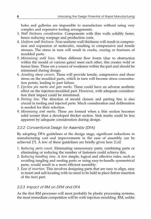
Initial work at Loughborough University has investigated the use of designoptimisation to create complex internal structures. Figure 2.2 illustrates a
Figure 2.1 Proposed Beijing National Stadium designed by Arup [8]
10 Unlocking the Design Potential of Rapid Manufacturing
diesel front plate manufactured by Delphi Diesel Systems showing internalflow channels that have to be conventionally gun-drilled.
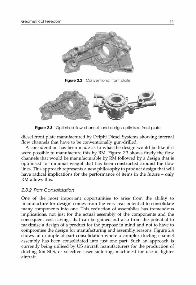
A consideration has been made as to what the design would be like if itwere possible to manufacture this by RM. Figure 2.3 shows firstly the flowchannels that would be manufacturable by RM followed by a design that isoptimised for minimal weight that has been constructed around the flowlines. This approach represents a new philosophy to product design that willhave radical implications for the performance of items in the future – onlyRM allows this.
2.3.2 Part Consolidation
One of the most important opportunities to arise from the ability to‘manufacture for design’ comes from the very real potential to consolidatemany components into one. This reduction of assemblies has tremendousimplications, not just for the actual assembly of the components and theconsequent cost savings that can be gained but also from the potential tomaximise a design of a product for the purpose in mind and not to have tocompromise the design for manufacturing and assembly reasons. Figure 2.4shows an example of part consolidation where a complex ducting channelassembly has been consolidated into just one part. Such an approach iscurrently being utilised by US aircraft manufacturers for the production ofducting (on SLS, or selective laser sintering, machines) for use in fighteraircraft.
Figure 2.2 Conventional front plate
Figure 2.3 Optimised flow channels and design optimised front plate
Geometrical Freedom 11

Work has been undertaken at Loughborough into the concept of partsconsolidation. Figure 2.5 shows how an assembly of over 25 parts has beenconsolidated into just one piece (with an extra cover) and then manufacturedby stereolithography (SL). Early calculations suggest that, not withstandingthe material properties, the SL pod would be commercially viable due to thelow number that would be manufactured and also the advantages that aregained by consolidating the assembly into just one part.
Another example of parts consolidation from Loughborough Universityinvolves the redesign and manufacture of car door handles with Jaguar Cars.An initial assembly comprising eleven components made from eight differ-ent materials was simplified to a single component made from a singlematerial that was manufactured by SLS. In this case the work showed howthe design freedoms afforded by RM could ease the end-of-life recycling.
2.3.3 Body Fitting Customisation
The production of body fit parts and core customisation is not novel.However, the creation of customised products using conventional skillsand technologies, especially truly body fitting customised products, hastraditionally been very labour-intensive and essentially craft-based. Thus,partly due to the costs of labour, customised products are usually out ofreach of the general public, who are forced to buy mass-produced goods.
Figure 2.4 Example of parts consolidation in aircraft ducting [9]
Figure 2.5 Consolidation of the control pod
12 Unlocking the Design Potential of Rapid Manufacturing

As true customisation is at present not feasible for the mass market, theconcept of ‘mass customisation’ is currently employed to give some degreeof customisation. However, mass customisation is really achieved by‘modularisation’ – the production of modules that can be bolted togetherin varying configurations, which that gives the economies of mass produc-tion but allows some choice in the product. By using management techni-ques such as postponement, the decision of how the final product isconfigured can be delayed to allow for greater degrees of customisation.However, standard manufacturing techniques are still employed (for themodules) and therefore there is still the need for costly tooling.
However, through the adoption of reverse engineering and Rapid Man-ufacturing, the era of cost-effective customisation for the masses is not faroff. With the advent of RM the production method and processes involvedfor customised parts would not change from part to part. Thus, the economicargument for providing core (body fitting) customisation is greatlyenhanced. This approach is already commercial reality as Siemens andPhonak are using laser sintering and stereolithography to manufacturebespoke hearing aids for end use (see Chapter 12).
At Loughborough University, this approach is being further considered bythe MANRM project (under a DTI Foresight Vehicle Initiative) where amethodology has been established for the capture of the correct deformedgeometry that is required for creating the body fitting customised parts.This project is particularly focused on the aerospace/automotive sectors.Figure 2.6 shows a body fitting seat that has been produced for one of theproject partners, MG Rover. The parts are then manufactured automaticallyusing RM technologies that require no expensive tooling. In the near future,this work will lead to affordable custom fitting products for the general public.
2.3.4 Multiple Assemblies: Textiles
An entirely novel area that has received virtually no consideration for RM,but one that has vast and exciting potential for future applications is that ofsmart textiles. Conventional sheet textiles, as with any other product, have tobe constructed with the manufacturing process in mind and thus textiles are
Figure 2.6 Body fitting seating platform and seat for the MG SV. (Reproduced withpermission of MG Rover Group)
Geometrical Freedom 13

fundamentally limited by the need to design for manufacture. Conventionalfabric/textile construction uses centuries-old principles – the key for RMfabrics (at present) is to move from continuous fibres to individual links.This was first proposed by Jiri Evenhuis and Janne Kyttanen [10] in 1999.This is demonstrated in Figure 2.7.
However, there are many research issues that need to be overcome beforeRM produced garments are a reality. These research issues include:
� Link design� Generation of three-dimensional data� Lofting of data over conformal surfaces� Very large data sets� Collapsing of the structures for efficient manufacture� Rapid Manufacturing process resolution
One of the most fundamental issues for creating body fitting RM textiles isthe difficulty of using current CAD systems, which are not intended orcapable of creating such complex assemblies. However, the LoughboroughRapid Manufacturing Research Group (in collaboration with NottinghamUniversity Composite Materials Research Group) have developed a pre-liminary methodology to wrap textile links over complex surfaces and thenmanufacture them by SLS. This is shown in Figure 2.8.
Figure 2.7 Comparison of conventional versus RM textiles
Figure 2.8 Wrapping of links over complex surfaces
14 Unlocking the Design Potential of Rapid Manufacturing

The current manufacture of all RM textile sheets, garments or productsrequires the design and CAD data to directly mimic the finished componentin its three-dimensional form (as shown in Figure 2.8). Therefore, in order tofit the garment in the build envelope and also limit the z height or number oflayers (and thus minimise the cost), it is necessary to then collapse thesedata into a manufacturable form. Initial work has established a methodologyfor performing this for simple link constructions (as demonstrated inFigure 2.9), but much work is required to extend this to more complexconstructions.
In summary, it is postulated that future RM systems will be capable ofcreating textiles directly and will be extended to the automated generation ofthe items that they are assembled into (e.g. clothing) using RM as theenabling technology. As a demonstration, Figure 2.10 shows an exampleof an RM dress that has been produced using current laser sinteringtechnologies, which is the world’s first fully conformal (body fitting) textile
Figure 2.9 Structure collapsing for efficient manufacture
Figure 2.10 Examples of laser sintered fabrics produced at Loughborough
Geometrical Freedom 15

garment to be produced directly in its assembled state. This, again, is onlyachievable by utilising an additive manufacturing approach.
Work is now underway aimed at investigating the potential for micro-level design and manufacture in the context of RM and initiating researchinto the automated knowledge-based generation of design optimised smarttextiles producible via RM. In the future, there is much scope for:
� Seamless garments that can be manufactured fully assembled� Variable ‘weave’� Products that transition from a solid to a textile configuration, thus giving
possibilities for optimised footwear� Smart textiles with built-in functionality (e.g. truly wearable computers,
built-in chemical/biological detection, custom fitting armoured jackets,etc.)
2.4 Material Combinations
When objects are formed in moulds, they are generally formed in onehomogeneous material. Even in the case of an over-moulded component,where there can be two or more homogeneous materials in one finished part,there is a definitive boundary between one material and the other. In thefuture, with some of the additive manufacturing processes there is thepotential to mix and grade materials in any combination that is desired,thus enabling materials with certain properties to be deposited where theyare needed [11,12].
The over-moulding technique is a classic example of how design canbe influenced by the availability of a manufacturing technique. Over-moulding allows designers, within limits, the ability to produce partsthat have added functionality and enhanced design. Indeed, the designof over-moulded components very often incorporates different materialcombinations to accentuate the design to the extent that designers areable to exploit the delineation of the different materials used to producedesign features as well as extra functionality. This is perfectly illustrated bythe simple case of a toothbrush – an everyday item that will often includeover-moulding to give a handle that is stiff, with an over-moulded grip anda different material at the neck to give a flexible head. This is illustrated inFigure 2.11.
Given that RM potentially allows the development of multiple materials tobe deposited in any location or combination that the designer requires, thishas potentially enormous implications for the functionality and aestheticsthat can be designed into parts. This concept of functionally gradedmaterials (FGMs) is further discussed in Chapter 7.
16 Unlocking the Design Potential of Rapid Manufacturing

2.5 Summary
The possibilities offered by Rapid Manufacturing are enormous. Suddenly,designers will be able to manufacture almost any shape that they come upwith and will no longer be constrained by the necessity to produce parts inmoulds. In addition, using processes such as the laser sintering of dissimilarpowders, RM will provide designers with new and exotic materials notavailable to other manufacturing processes.
At the design phase, RM allows almost whatever shape is desired as themould process will no longer limit design. This means objects can bedesigned with re-entrant features, no draft angles, unlimited wall thicknessand increased complexity, with none of the limitations imposed by either themoulding process or the tool making process, as neither will be required.
One of the most profound implications of RM on design will be that,without the cost of tooling to amortise into the parts produced, eachcomponent can be different, potentially allowing for true mass customisa-tion of each and every product. With developments in web-enabled soft-ware, high levels of computer literacy and Internet connectivity in the home,the technologies are not far from giving the consumer the ability to modifythe design of the product they desire for themselves. Although some wayoff, it is conceivable that the consumer may – for a price – want to influencethe design of their new sunglasses, mobile phone casing, steering wheel grip,surgical instrument, prosthetic part or favourite kitchen utensil, etc., andthen send the data back to the manufacturer to be made for them.
RM will become more of a reality when the properties of the materialsthat are produced become more acceptable and consistent. This materialsresearch is one of the main stumbling blocks to the adoption of these
Figure 2.11 Example of how over-moulding improves design and functionality
Summary 17

additive manufacturing techniques for end-use parts and is the subject ofmuch current research. However, many organisations are willing to acceptthe materials limitations that are in evidence today to gain an advantagefrom the design possibilities.
References
1. Boothroyd, G., Dewhurst, P. and Knight, W. (1994) Product Design forManufacture and Assembly, Marcel Dekker Inc., New York.
2. Mansour, S. and Hague, R. (2003) Impact of rapid manufacturingon design for manufacture for injection moulding, Proceedings of theInstitution of Mechanical Engineers, Part B: Journal of Engineering Manu-facture, 217(B4), 453–61.
3. UK manufacturing: we can make it better, Foresight Manufacturing 2020Panel, Final Report, Findlay Publications, p. 12.
4. Campbell, R.I., Hague, R.J.M., Sener, B. and Wormald, P.W. (2003) Thepotential for the bespoke industrial designer, The Design Journal, 6(3),24–34.
5. Hague, R.J., Campbell, R.I. and Dickens, P.M. (2003) Implications ondesign of rapid manufacturing, Proceedings of the Institution of MechanicalEngineers, Part C: Journal of Mechanical Engineering Science, 217(C1), 25–30.
6. Poli, C. (2001) Design for Manufacturing, A Structured Approach,Butterworth- Heinemann, Boston, Massachusetts.
7. Fox, S., Marsh, L. and Cockerham, G. (2001) Design for manufacture: astrategy for successful application to building, Construction Managementand Economics, 19, 493–502.
8. www.arup.com9. www.3dsystems.com
10. www.freedomofcreation.com11. Anon (2001) The solid future of rapid prototyping, The Economist
Technology Quarterly, 24 March 2001, pp. 47–9.12. Jacobs, P.F. (2002) From stereolithography to LENS: a brief history of laser
fabrication, International Conference on Metal Powder Deposition for RapidManufacturing, San Antonio, Texas, 8–10 April 2002.
18 Unlocking the Design Potential of Rapid Manufacturing