university of washington accessibility guidelines...accessible routes. see figure 4-2. 6. avoid...
TRANSCRIPT

University of Washington Accessibility Guidelines
December 2019 – Version 1.0

Table of Contents 1. Purpose ........................................................................................................................................... 1
2. References ...................................................................................................................................... 1
3. Terminology .................................................................................................................................... 2
4. Design Elements ............................................................................................................................. 3
4.1. Exterior Accessible Routes ...................................................................................................... 3
Exterior Walkway Surfaces.............................................................................................. 3
Exterior Ramps ................................................................................................................ 4
Curb Ramps ..................................................................................................................... 6
Exterior Stairways ........................................................................................................... 7
Parking............................................................................................................................. 8
Exterior Accessible Wayfinding ....................................................................................... 9
Bus Stops ....................................................................................................................... 11
Site Furniture ................................................................................................................ 11
Doors ............................................................................................................................. 11
Operable Parts .............................................................................................................. 12
4.2. Interior Accessible Routes .................................................................................................... 13
Interior Walkway Surfaces ............................................................................................ 13
Interior Ramps............................................................................................................... 13
Interior Stairways .......................................................................................................... 14
Elevators ........................................................................................................................ 14
Doors ............................................................................................................................. 15
4.3. Building Elements ................................................................................................................. 16
Plumbing Elements and Facilities ................................................................................. 16
Communication Elements ............................................................................................. 18
Special Rooms, Spaces, Elements ................................................................................. 19
5. Measurement ............................................................................................................................... 21
5.1. Precision and Accuracy of Measurement Tools ................................................................... 21
5.2. Measurement Process for Exterior Features ........................................................................ 21
Exterior Walkways ......................................................................................................... 21
Parking Areas ................................................................................................................ 23
Exterior Ramps and Curb Ramps................................................................................... 24
Horizontal Gaps and Vertical Alignment ....................................................................... 26
Exterior Cast-in-Place Stairways ................................................................................... 27
6. Accepted Tolerances .................................................................................................................... 27
6.1. Accepted Exterior Walkway Tolerances ............................................................................... 27
6.2. Accepted Parking Area Tolerances ....................................................................................... 27
6.3. Accepted Exterior Ramp and Curb Ramp Tolerances ........................................................... 27
6.4. Accepted Horizontal Gaps and Vertical Alignment Tolerances ............................................ 28
6.5. Accepted Exterior Stairway Tolerances ................................................................................ 28

University of Washington Accessibility Guidelines December 2019 Version 1.0
Page | 1
1. Purpose
The University of Washington strives to ensure that people with disabilities are included and have access to programs, services and activities throughout the institution. This work aligns to the University’s vision to educate a diverse student body and its values of integrity, diversity, excellence, collaboration, innovation and respect.
In order to achieve accessibility for students, staff, faculty, and visitors with disabilities across all campuses, the University of Washington expects the built environment to be designed and constructed to meet the 2010 ADA Standards for Accessible Design. In pursuit of this goal, the following document contains common 2010 ADA standards to be followed by designers, contractors, and University staff and faculty. All design and construction work shall comply with all applicable sections of the 2010 ADA Standards for Accessible Design and the full standards document should be sought out for further detail than what is provided in this guideline.
For certain elements within this document, the University of Washington provides additional guidance that includes more conservative requirements than the 2010 ADA Standards (and are shown in italic font). These requirements should be adhered to for the greatest extent possible before the 2010 ADA Standards are implemented. When the University’s preferred design standard cannot be achieved, the design decision should be documented and discussed with the University’s construction and design staff. If the 2010 ADA Standards also cannot be met, the design should meet the 2010 ADA standards to the maximum extent feasible. The design documentation should be included in the University’s standard MEF format.
2. References
(2010). 2010 ADA Standards for Accessible Design. Department of Justice.
Architectural Research Consulting. (2011). Dimensional Tolerances in Construction and for Surface Accessibility. United States Access Board.
Development Division, Design Office. (2019). Standard Plans. Washington Department of Transportation.
(n.d.). Guide to the ADA Standards. United States Access Board.
(2011). Proposed Guidelines for Pedestrian Facilities in the Public Right-of-Way. United State Access Board.
(2009 with May 2012 revision). Manual on Uniform Traffic Control Devices for Streets and Highways. US Department of Transportation Federal Highway Administration.
(2011). Proposed Guidelines for Pedestrian Facilities in the Public Right-of-Way. United State Access Board.

University of Washington Accessibility Guidelines December 2019 Version 1.0
Page | 2
3. Terminology
Accessible. A site, building, facility, or portion thereof that complies with this part.
Cross Slope. The slope that is perpendicular to the direction of travel (see running slope).
Curb Ramp. A short ramp cutting through a curb or built up to it.
Detectable Warning. A standardized surface feature built in or applied to walking surfaces or other elements to warn of hazards on a circulation path. Also known as “truncated domes”.
Grade Break. The line where two surface planes with different grades meet.
Operable Part. A component of an element used to insert or withdraw objects, or to activate, deactivate, or adjust the element.
Pedestrian Access Route. A continuous and unobstructed path of travel provided for pedestrians with disabilities within or coinciding with a pedestrian circulation path.
Pedestrian Circulation Path. A prepared exterior or interior surface provided for pedestrian travel.
Ramp. A walking surface that has a running slope steeper than 1:20.
Running Slope. The slope that is parallel to the direction of travel (see cross slope).
Ramp Flare. Transitions the curb line to the elevation of the street.
Turning Space. Area that provides maneuvering space commonly found at the top/bottom of a ramp and doorways.
Vertical Surface Discontinuities. Vertical differences in level between two adjacent surfaces.
University of Washington Accessibility Guidelines December 2019 Version 1.0
Section 4.1 - Exterior Accessible Routes Page | 3
4. Design Elements
4.1. Exterior Accessible Routes
Exterior Walkway Surfaces
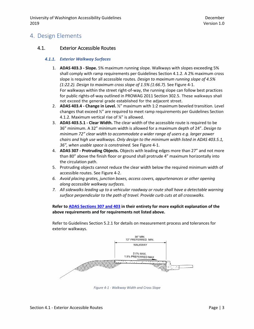
1. ADAS 403.3 - Slope. 5% maximum running slope. Walkways with slopes exceeding 5% shall comply with ramp requirements per Guidelines Section 4.1.2. A 2% maximum cross slope is required for all accessible routes. Design to maximum running slope of 4.5% (1:22.2). Design to maximum cross slope of 1.5% (1:66.7). See Figure 4-1. For walkways within the street right-of-way, the running slope can follow best practices for public rights-of-way outlined in PROWAG 2011 Section 302.5. These walkways shall not exceed the general grade established for the adjacent street.
2. ADAS 403.4 - Change in Level. ½” maximum with 1:2 maximum beveled transition. Level changes that exceed ½” are required to meet ramp requirements per Guidelines Section 4.1.2. Maximum vertical rise of ¼” is allowed.
3. ADAS 403.5.1 - Clear Width. The clear width of the accessible route is required to be 36” minimum. A 32” minimum width is allowed for a maximum depth of 24”. Design to minimum 72” clear width to accommodate a wider range of users e.g. larger power chairs and high use walkways. Only design to the minimum width listed in ADAS 403.5.1, 36”, when usable space is constrained. See Figure 4-1.
4. ADAS 307 - Protruding Objects. Objects with leading edges more than 27” and not more than 80” above the finish floor or ground shall protrude 4” maximum horizontally into the circulation path.
5. Protruding objects cannot reduce the clear width below the required minimum width of accessible routes. See Figure 4-2.
6. Avoid placing grates, junction boxes, access covers, appurtenances or other opening along accessible walkway surfaces.
7. All sidewalks leading up to a vehicular roadway or route shall have a detectable warning surface perpendicular to the path of travel. Provide curb cuts at all crosswalks.
Refer to ADAS Sections 307 and 403 in their entirety for more explicit explanation of the above requirements and for requirements not listed above. Refer to Guidelines Section 5.2.1 for details on measurement process and tolerances for exterior walkways.
Figure 4-1 - Walkway Width and Cross Slope

University of Washington Accessibility Guidelines December 2019 Version 1.0
Section 4.1 - Exterior Accessible Routes Page | 4
Figure 4-2 - Limits of Protruding Objects (Guide to the ADA Standards)
Exterior Ramps
1. ADAS 405.2 - Slope. Ramp runs shall have a running slope not steeper than 1:12 (8.33%). Design ramp runs to a maximum running slope of 1:13.33 (7.5%).
2. ADAS 405.3 - Cross Slope. Cross slope of ramp runs shall not be steeper than 1:48. Design to a maximum cross slope of 1:66.7 (1.5%).
3. ADAS 405.4 - Floor or Ground Surfaces. Floor or ground surfaces of ramp runs shall comply with ADAS Section 302. See Figure 4-3.
4. Changes in level other than the running slope and cross slope are not permitted on ramp runs.
5. ADAS 405.5 - Clear Width. The clear width of a ramp run, between handrails, shall be 36” minimum. See Figure 4-4. Design to minimum 72” clear width to accommodate a wider range of users, e.g. larger power chairs and high use walkways. Only design to the minimum width listed in ADAS 405.5, 36”, when usable space is constrained.
6. ADAS 405.6 - Rise. The rise for any ramp run shall be 30” maximum. 7. ADAS 405.7 – Ramp Landing. Ramps shall have minimum 60” deep landings at the top
and the bottom of each ramp run. At the change of direction landings are required to be 60” x 60” minimum. Slopes in landings shall have a maximum slope of 1:48 (2%). Design to maximum slope of 1.5% (1:66.7). See Figure 4-3.
8. ADAS 405.7.2 - Landing Width. The landing clear width shall be at least as wide as the widest ramp run leading to the landing. See Figure 4-3.
9. ADAS 405.8 - Handrails. Ramps runs with a rise greater than 6” shall have handrails complying with ADAS Section 505.

University of Washington Accessibility Guidelines December 2019 Version 1.0
Section 4.1 - Exterior Accessible Routes Page | 5
10. ADAS 405.9 - Edge Protection. Edge protection shall be provided on each side of ramp runs and at each side of ramp landings. It can be a 4” high curb or railing that prevents the passage of a 4” diameter sphere. It can be an extended floor surface that extends 12” beyond the handrail on each side.
11. ADAS 505.2 - Handrails. Handrails shall be provided on both sides of the ramp. Per ADAS Section 505, Handrails shall be 1-1/2” minimum from wall surface. Handrails shall be 1-1/2” to 2” in diameter. Non-circular handrails shall meet ADAS Section 505.7.2.
12. ADAS 505.3 - Continuity. Handrails shall be continuous within the full length of each ramp run. Inside handrails on switchback ramps shall be continuous between runs.
13. ADAS 505.4 - Height. Top of gripping surfaces of handrails shall be 34” minimum and 38” maximum vertically above ramp surfaces. Handrails shall be at a consistent height above ramp surfaces. See Figure 4-4.
14. ADAS 505.10.1 - Top and Bottom Extension at Ramps. Ramp handrails shall extend horizontally above the landing for 12” minimum beyond the top and bottom of ramp runs. Extensions shall return to a wall, guard, or the landing surface, or shall be continuous to the handrail of an adjacent ramp run. See Figure 4-4.
Refer to ADAS Sections 405 and 505 in their entirety for more explicit explanation of the above requirements and for requirements not listed above. Refer to Guidelines Section 5.2.3 for details on measurement process and tolerances for exterior ramps.
Figure 4-3 - Ramp and Landing Configurations (Guide to the ADA Standards)

University of Washington Accessibility Guidelines December 2019 Version 1.0
Section 4.1 - Exterior Accessible Routes Page | 6
Figure 4-4 - Ramp Handrail Details
(Guide to the ADA Standards)
Curb Ramps
1. ADAS 405.2 - Slope. Ramp runs shall have a running slope not steeper than 1:12 (8.33%). Design ramp runs to a maximum running slope of 1:13.33 (7.5%).
2. ADAS 405.3 - Cross Slope. Cross slope of ramp runs shall not be steeper than 1:48. Design to a maximum cross slope of 1:66.7 (1.5%).
3. ADAS 405.4 - Floor or Ground Surfaces. Floor or ground surfaces of ramp runs shall comply with ADAS Section 302.
4. Changes in level other than the running slope and cross slope are not permitted on ramp runs.
5. ADAS 405.5 - Clear Width. The clear width of a ramp run shall be 36” minimum. Design to minimum 48” clear width to accommodate a wider range of users, e.g. larger power

University of Washington Accessibility Guidelines December 2019 Version 1.0
Section 4.1 - Exterior Accessible Routes Page | 7
chairs and high use walkways. Only design to the minimum width listed in ADAS 405.5, 36”, when usable space is constrained.
6. ADAS 406.2 - Counter Slope. Counter slope shall not be steeper than 1:20 (5%). 7. ADAS 406.3 - Sides of Curb Ramps. Where provided, curb ramp flares shall not be
steeper than 1:10 (10%). 8. ADAS 406.4 - Landings. Landings shall be provided on all curb ramps. Landings shall be
36” minimum length and be at least as wide as the curb ramp run width. Design to minimum 48” length to accommodate a wider range of users, e.g. larger power chairs. Where the landing is constrained at the back of sidewalk, the landing length (in the direction of the crossing) shall be designed to a minimum of 60”. Only design to the minimum width listed in ADAS 406.4, 36”, when usable space is constrained.
9. ADAS 406.6 - Diagonal Curb Ramps. Diagonal ramps should only be used when other types of directional ramps are not practical. There shall be a clear space at the bottom of the curb ramps at least 48” long x the width of the ramp run. The clear space shall be outside the active traffic lanes of the roadway. At marked crossings, the clear space shall be within the markings.
Refer to ADAS Sections 405 and 406 in their entirety for more explicit explanation of the above requirements and for requirements not listed above. Refer to Guidelines Section 5.2.3 for details on measurement process and tolerances for exterior ramps and Figure 4-5 for details on typical curb ramp elements.
Figure 4-5 - Curb Ramp Elements
(Guide to the ADA Standards) Exterior Stairways
1. ADAS 210.1 - General. Interior and exterior stairs that are part of a means of egress shall comply with ADAS Section 504.

University of Washington Accessibility Guidelines December 2019 Version 1.0
Section 4.1 - Exterior Accessible Routes Page | 8
2. ADAS 504.2 - Treads and Risers. All steps on a flight of stairs shall have uniform riser heights and uniform tread depths. Risers shall be 4” high minimum and 7” high maximum. Treads shall be 11” deep minimum.
3. ADAS 504.3 - Open Risers. Open risers are not permitted. 4. ADAS 505.2 - Handrails. Handrails shall be provided on both sides of the stairs. Per
ADAS Section 505, handrails shall be 1-1/2” minimum from wall surface. Handrails shall be 1-1/2” to 2” in diameter. Non-circular handrails shall meet ADAS Section 505.7.2.
5. ADAS 505.3 - Continuity. Handrails shall be continuous within the full length of each stair flight. Inside handrails on switchback stairs shall be continuous between flights.
6. ADAS 505.4 - Height. Top of gripping surfaces of handrails shall be 34” minimum and 38” maximum vertically above stair nosing. Handrails shall be at a consistent height above stair nosing.
7. ADAS 505.10.2, 505.10.3 - Top and Bottom Extension at Stairs. At the top of a stair flight, handrails shall extend horizontally above the landing for 12” minimum beginning directly above the first riser nosing. At the bottom of a stair flight, handrails shall extend at the slope of the stair flight for a horizontal distance at least equal to one tread depth beyond the last riser nosing. Extensions shall return to a wall, guard, or the landing surface, or shall be continuous to the handrail of an adjacent stair flight.
Refer to ADAS Sections 504 and 505 in their entirety for more explicit explanation of the above requirements and for requirements not listed above. Refer to Guidelines Section 5.2.5 for details on measurement process and tolerances for exterior stairways.
Parking
1. ADAS 502.1 - General. Where parking spaces are marked, the width of the parking space shall be measured to the center of the marking.
2. ADAS 502.2 - Vehicle Spaces. Car Parking spaces shall be 96” wide minimum and van parking spaces shall be 132” wide minimum and shall have an adjacent access aisle complying with ADAS Section 502.3. Van parking spaces can be 96” wide minimum if the access aisle is 96” wide minimum. It is UW Transportation Services preference to have all ADA stalls be van accessible to accommodate all vehicles and UW Dial-a-Ride service.
3. ADAS 502.3 - Access Aisle. Access aisle shall adjoin accessible route. 4. ADAS 502.3.1 - Width. Access aisles for car and van parking spaces shall be 60” wide
minimum. 5. ADAS 502.3.3 - Marking. Access aisles shall be marked to discourage parking in them. 6. ADAS 502.4 - Floor or Ground Surfaces. Access aisles shall be at the same level as the
parking spaces they serve. Slopes in landings shall have a maximum slope of 1:48 (2%). Design to maximum slope of 1.5% (1:66.7).
7. ADAS 502.5 - Vertical Clearance. Parking spaces for vans and access aisles and vehicular routes serving them shall provide a vertical clearance of 98” minimum.
8. ADAS 502.6 - Identification. Signs identifying van parking spaces shall contain the designation “van accessible”. Signs shall be 60” minimum above the finish floor or ground surface measured to the bottom of the sign.
9. See Figure 4-1 for example accessible stall arrangements for 90° and 60° typical and van accessible stalls.

University of Washington Accessibility Guidelines December 2019 Version 1.0
Section 4.1 - Exterior Accessible Routes Page | 9
10. Metered accessible parking spaces shall include curb cuts and sidewalk access to the meter.
Figure 4-6 - Example Accessible Stall Arrangements
Refer to ADAS Section 502 in its entirety for more explicit explanation of the above requirements and for requirements not listed above.
Refer to Guidelines Section 5.2.2 for details on measurement process and tolerances for parking areas.
Exterior Accessible Wayfinding
Purpose of Accessible Wayfinding
Accessible Wayfinding is intended to direct pedestrians to their desired destination along ADA-accessible routes. The wayfinding should fully direct pedestrians from

University of Washington Accessibility Guidelines December 2019 Version 1.0
Section 4.1 - Exterior Accessible Routes Page | 10
their origin to destination. Origins include ADA parking stalls, bus stops, or public sidewalk entries. Destinations include any accessible building entrance or amenity on campus. Without adequate wayfinding, a person requiring ADA accommodations may chose the wrong path and encounter a barrier often necessitating back tracking to find another route.
Main Wayfinding Sign Classes
Map Kiosks: Map kiosks are large signs with maps showing location and orientation of the map, as well as accessible route information, directional arrows to buildings and parking structures, and symbology for ADA information and other campus amenities Guide Signs: The two subcategories of guide signs, pavement inserts and guide posts, contain similar information with the intent of reassuring pedestrians that they are on the right path. Guide signs should be placed at pathway junctions or long stretches of continuous pathways and contain directional arrows to buildings and parking structures. Building Signs: Building signs are used to identify specific buildings. These signs contain building names, descriptions, and departments housed in the building. Building signs should be considered near all accessible entrances to buildings. Temporary Construction Signs: Temporary Construction signs provide guidance on closed pedestrian routes and alternative pedestrian routes that can be used during construction staging that affects established pedestrian routes.
Placement of Accessible Wayfinding
Wayfinding signs should be placed at important origins, destinations, and decision points in the accessible route network. The messaging of the signs should be clear in directing pedestrians to the appropriate destinations using ADA symbology, high contrast text, and directional arrows. High volume locations such as parking garages and main campus buildings may also have map kiosks with clearly marked accessible routes through campus, accessible parking locations, and accessible building entrances. It is expected for a typical project that involves new building construction or alterations to existing entryways or destinations that accessible building entry signage be included in the project scope with installation of ground mounted wayfinding dependent on the type of project. Temporary construction signs along pedestrian routes are necessary when routes are closed or altered due to construction activities and require an alternate route to be designated. Closed routes should be clearly signed at the closure and in advance of the closure where an alternate path would need to be taken. In high pedestrian use areas, implementation of flaggers to guide pedestrians can be beneficial to add extra guidance for routes that are difficult to traverse. PROWAG R205 - Alternative Pedestrian Access Routes. When a pedestrian circulation path is temporarily closed by construction, alterations, maintenance operations, or other conditions, an alternative pedestrian access route complying with section 6D.01, 6D.02, 6G.05 of the MUTCD shall be provided. Where provided,

University of Washington Accessibility Guidelines December 2019 Version 1.0
Section 4.1 - Exterior Accessible Routes Page | 11
pedestrian barricades and channelizing devices shall comply with sections 6F.63, 6D.68, and 6F.71 of the MUTCD.
Bus Stops
1. ADAS 810.2.2 - Bus Boarding and Alighting Areas. Bus stop boarding and alighting areas shall have a clear space of 96” minimum length (measured perpendicular to roadway) and 60” minimum width (measured parallel to the roadway).
2. ADAS 810.2.3 - Connection. Bus stop boarding and alighting areas shall be connected to streets, sidewalks, or pedestrian paths by an accessible route.
3. ADAS 810.3 - Bus Shelters. Bus shelters shall provide a minimum clear floor or ground space complying with ADAS Section 305 entirely within shelter. Bus shelter shall be connected by accessible route to the boarding and alighting area.
Refer to ADAS Section 810 in its entirety for more explicit explanation of the above requirements and for requirements not listed above.
Site Furniture
Not governed by the ADA unless considered a work or dining surface, per ADAS Section 902. 1. ADAS 902.2 - Clear Floor or Ground Space. A 30” x 48” clear floor space complying with
ADAS Section 305 positioned for a forward approach shall be provided. Knee and toe clearance complying with ADAS Section 306 shall be provided.
2. ADAS 902.3 - Height. The tops of dining surfaces and work surfaces shall be 28” minimum and 34” maximum above the finish floor or ground.
3. Ensure an accessible route is provided to and within areas with site furniture.
Doors
In new construction, entrances on an accessible route, including the main entrance, shall be designed for universal accessibility and shall provide power-operated doors. If an entrance to the building other than the main entrance is located closer to the parking designated for persons with disabilities, that entrance shall also be accessible with power-operated door(s). 1. ADAS 404.2.3 - Clear Width. The clear width shall be 32” minimum with door in 90-
degree open position. Double doors require at least one leaf to provide 32” clear width. 2. ADAS 404.2.4 - Door Maneuvering Clearances. Door Maneuvering clearance is required
to be provided per ADAS Table 404.2.4.2. 3. ADAS 404.2.5 - Thresholds. Thresholds are required to be ½” maximum high with a 1:2
maximum. Existing thresholds are allowed to be 3/4” maximum with 1:2 bevel. 4. ADAS 404.2.7 - Hardware. Hardware is required to be lever style and be mounted 38” to
48” above the finish floor. 5. ADAS 404.2.9 - Interior Door Force. Interior door force is required to be 5 pounds
maximum. 6. WAC 51-50, 1101.2.2 - Exterior door force. Exterior door force is required to be 10
pounds maximum. 7. Doors larger than 3’ x 7’ in rooms open to the public must be power operable. 8. For new construction, primary entrances to buildings should be universally accessible.
Refer to ADAS Section 404 in its entirety for more explicit explanation of the above requirements and for requirements not listed above.

University of Washington Accessibility Guidelines December 2019 Version 1.0
Section 4.1 - Exterior Accessible Routes Page | 12
Operable Parts
1. ADAS 309.2 - Clear Floor Space. A clear floor or ground space complying with ADAS Section 305 shall be provided. A level (<2% slope, design to <1.5%) 30” x 48” clear floor space positioned for a forward or parallel approach. Knee and toe clearance of 27” minimum high x 17” minimum deep complying with ADAS Section 306 shall be provided.
2. ADAS 309.3 - Height. Operable parts shall be placed within one or more of the reach ranges specified in ADAS Section 308.
3. ADAS 309.4 - Operation. Operable parts shall be operable with one hand and shall not require tight grasping, pinching, or twisting of the wrist. The force required to activate operable parts shall be 5 pounds maximum.
4. Elements required to meet the operable parts standards include parking pay stations, accessible signage, electric vehicle charging stations, blue emergency phone stations, and interactive kiosks.
Refer to ADAS Sections 308, 309, and 306 in their entirety for more explicit explanation of the above requirements and for requirements not listed above.
University of Washington Accessibility Guidelines December 2019 Version 1.0
Section 4.2 - Interior Accessible Routes Page | 13
4.2. Interior Accessible Routes
Interior Walkway Surfaces
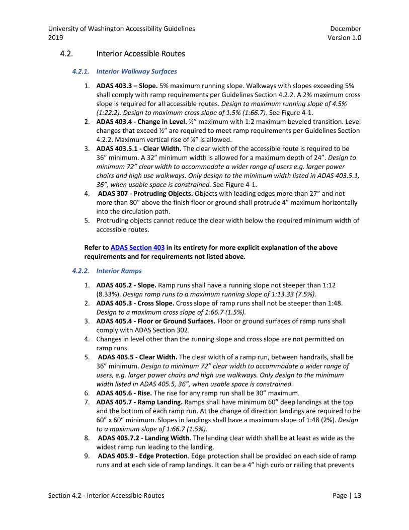
1. ADAS 403.3 – Slope. 5% maximum running slope. Walkways with slopes exceeding 5% shall comply with ramp requirements per Guidelines Section 4.2.2. A 2% maximum cross slope is required for all accessible routes. Design to maximum running slope of 4.5% (1:22.2). Design to maximum cross slope of 1.5% (1:66.7). See Figure 4-1.
2. ADAS 403.4 - Change in Level. ½” maximum with 1:2 maximum beveled transition. Level changes that exceed ½” are required to meet ramp requirements per Guidelines Section 4.2.2. Maximum vertical rise of ¼” is allowed.
3. ADAS 403.5.1 - Clear Width. The clear width of the accessible route is required to be 36” minimum. A 32” minimum width is allowed for a maximum depth of 24”. Design to minimum 72” clear width to accommodate a wider range of users e.g. larger power chairs and high use walkways. Only design to the minimum width listed in ADAS 403.5.1, 36”, when usable space is constrained. See Figure 4-1.
4. ADAS 307 - Protruding Objects. Objects with leading edges more than 27” and not more than 80” above the finish floor or ground shall protrude 4” maximum horizontally into the circulation path.
5. Protruding objects cannot reduce the clear width below the required minimum width of accessible routes.
Refer to ADAS Section 403 in its entirety for more explicit explanation of the above requirements and for requirements not listed above.
Interior Ramps
1. ADAS 405.2 - Slope. Ramp runs shall have a running slope not steeper than 1:12 (8.33%). Design ramp runs to a maximum running slope of 1:13.33 (7.5%).
2. ADAS 405.3 - Cross Slope. Cross slope of ramp runs shall not be steeper than 1:48. Design to a maximum cross slope of 1:66.7 (1.5%).
3. ADAS 405.4 - Floor or Ground Surfaces. Floor or ground surfaces of ramp runs shall comply with ADAS Section 302.
4. Changes in level other than the running slope and cross slope are not permitted on ramp runs.
5. ADAS 405.5 - Clear Width. The clear width of a ramp run, between handrails, shall be 36” minimum. Design to minimum 72” clear width to accommodate a wider range of users, e.g. larger power chairs and high use walkways. Only design to the minimum width listed in ADAS 405.5, 36”, when usable space is constrained.
6. ADAS 405.6 - Rise. The rise for any ramp run shall be 30” maximum. 7. ADAS 405.7 - Ramp Landing. Ramps shall have minimum 60” deep landings at the top
and the bottom of each ramp run. At the change of direction landings are required to be 60” x 60” minimum. Slopes in landings shall have a maximum slope of 1:48 (2%). Design to a maximum slope of 1:66.7 (1.5%).
8. ADAS 405.7.2 - Landing Width. The landing clear width shall be at least as wide as the widest ramp run leading to the landing.
9. ADAS 405.9 - Edge Protection. Edge protection shall be provided on each side of ramp runs and at each side of ramp landings. It can be a 4” high curb or railing that prevents

University of Washington Accessibility Guidelines December 2019 Version 1.0
Section 4.2 - Interior Accessible Routes Page | 14
the passage of a 4” diameter sphere. It can be an extended floor surface that extends 12” beyond the handrail on each side.
10. ADAS 505.2 - Handrails. Handrails shall be provided on both sides of the ramp. Per ADAS Section 505, Handrails shall be 1-1/2” minimum from wall surface. Handrails shall be 1-1/2” to 2” in diameter. Non-circular handrails shall meet ADAS Section 505.7.2.
11. ADAS 505.3 - Continuity. Handrails shall be continuous within the full length of each ramp run. Inside handrails on switchback ramps shall be continuous between runs.
12. ADAS 505.4 - Height. Top of gripping surfaces of handrails shall be 34” minimum and 38” maximum vertically above ramp surfaces. Handrails shall be at a consistent height above ramp surfaces.
13. ADAS 505.10.1 - Top and Bottom Extension at Ramps. Ramp handrails shall extend horizontally above the landing for 12” minimum beyond the top and bottom of ramp runs. Extensions shall return to a wall, guard, or the landing surface, or shall be continuous to the handrail of an adjacent ramp run.
Refer to ADAS Sections 405 and 505 in their entirety for more explicit explanation of the above requirements and for requirements not listed above.
Interior Stairways
1. ADAS 210.1 - General. Interior and exterior stairs that are part of a means of egress shall comply with ADAS Section 504.
2. 504.2 Treads and Risers - All steps on a flight of stairs shall have uniform riser heights and uniform tread depths. Risers shall be 4” high minimum and 7” high maximum. Treads shall be 11” deep minimum.
3. ADAS 504.3 - Open Risers. Open risers are not permitted. 4. ADAS 505.2 - Handrails. Handrails shall be provided on both sides of the stairs. Per
ADAS Section 505, Handrails shall be 1-1/2” minimum from wall surface. Handrails shall be 1-1/2” to 2” in diameter. Non-circular handrails shall meet ADAS Section 505.7.2.
5. ADAS 505.3 - Continuity. Handrails shall be continuous within the full length of each stair flight. Inside handrails on switchback stairs shall be continuous between flights.
6. ADAS 505.4 - Height. Top of gripping surfaces of handrails shall be 34” minimum and 38” maximum vertically above stair nosing. Handrails shall be at a consistent height above stair nosing.
7. 505.10.2, 505.10.3 - Top and Bottom Extension at Stairs. At the top of a stair flight, handrails shall extend horizontally above the landing for 12” minimum beginning directly above the first riser nosing. At the bottom of a stair flight, handrails shall extend at the slope of the stair flight for a horizontal distance at least equal to one tread depth beyond the last riser nosing. Extensions shall return to a wall, guard, or the landing surface, or shall be continuous to the handrail of an adjacent stair flight.
Refer to ADAS Sections 504 and 505 in their entirety for more explicit explanation of the above requirements and for requirements not listed above.
Elevators
1. ADAS 407.2.1 - Call Controls. Where elevator call buttons or keypads are provided, they shall be raised or flush. Hall call buttons shall be ¾” minimum in the smallest dimension. They shall be mounted between 15” to 48” maximum above the finish floor. A level

University of Washington Accessibility Guidelines December 2019 Version 1.0
Section 4.2 - Interior Accessible Routes Page | 15
(<2% slope, design to 1.5%) 30” x 48” clear floor space shall be provided at the call controls. The “up” button shall be located above the “down” button.
2. ADAS 407.2.2 - Hall Signals. Hall signals, including in-car signals, shall be visible and audible. Visible signals 2-1/2” minimum for each direction and shall be centered at 72” above the finish floor. Signals shall be visible from the floor area adjacent to the hall call button. Audible signals shall sound once for the up direction and twice for the down direction or shall have verbal annunciators that indicate the direction of elevator car travel.
3. ADAS 407.2.3 - Hoistway Signs. Signs at elevator hoistways shall comply with ADAS Section 407.2.3. Floor Designation. Floor designations complying with ADAS Sections 703.2 and 703.4.1 shall be provided on both jambs of elevator hoistway entrances. Floor designations shall be provided in both tactile characters and braille. Tactile characters shall be 2” high minimum. A tactile star shall be provided on both jambs at the main entry level.
4. ADAS 407.4 - Elevator Car Dimensions. Inside dimensions of elevator cars and clear width of elevator doors shall comply with ADAS Table 407.4.1.
5. ADAS 407.4.6 - Elevator Car Controls. Where provided, elevator car controls shall be mounted between 15” minimum and 48” maximum above the finish floor. Where the elevator panel serves more than 16 openings or it is an existing elevator, and a parallel approach is provided, buttons with floor designations shall be permitted to be 54” maximum above the finish floor. Buttons shall be arranged with numbers in ascending order. When two or more columns of buttons are provided they shall read from left to right. Emergency control buttons shall have their centerlines 35” minimum above the finish floor and shall be grouped at the bottom of the panel.
Refer to ADAS Section 407 in its entirety for more explicit explanation of the above requirements and for requirements not listed above.
Doors
1. Refer to Guidelines Section 4.1.9 as Interior and Exterior doors have the same requirements with exception of noted door force.

University of Washington Accessibility Guidelines December 2019 Version 1.0
Section 4.3 - Building Elements Page | 16
4.3. Building Elements
Plumbing Elements and Facilities
Drinking Fountains
1. ADAS 602.2 - Clear Floor Space. A level (<2% slope, design to <1.5%) 30” x 48” clear floor space positioned for a forward approach and centered on the unit shall be provided. Knee and toe clearance of 27” minimum high x 17” minimum deep complying with ADAS Section 306 shall be provided.
2. ADAS 602.4 - Spout. The spout is required to be 36” maximum above the finish floor and 3-1/2” maximum from the front edge of fountain.
3. ADAS 602.6 - Water Flow. The spout shall provide a flow of water 4” high minimum and shall be located 5” maximum from the front of the unit.
4. ADAS 602.7 - Standing Persons Spout. The spout shall be mounted between 38” minimum to 43” maximum above the finish floor.
Refer to ADAS Section 602 in its entirety for more explicit explanation of the above requirements and for requirements not listed above.
Restrooms
1. ADAS 603.2.1 - Turning Space. Turning 60” diameter or “T” turning space shall be provided within the room.
2. ADAS 603.2.3 - Door Swing. With exception of single user toilet rooms that have 30” x 48” clear floor space beyond the door swing, doors shall not swing into the clear floor space or clearance required for any fixture. Doors shall be permitted to swing into the required turning space.
3. ADAS 603.3 - Mirrors. Mirrors located above lavatories or countertops shall be installed with the bottom edge of the reflecting surface 40” maximum above the finish floor. Mirrors not located above lavatories or countertops shall be installed with the bottom edge of the reflecting surface 35” maximum above the finish floor.
4. ADAS 604 - Water Closet. The centerline of the water closet shall be positioned 16” minimum to 18” maximum from the side wall. Flush controls are required to be on the “open” side of the toilet stall or room.
5. ADAS 604.3 - Water Closet Clearance. Clearance around a water closet shall be 60” minimum measured perpendicular from the side wall to nearest obstruction and 56” minimum measured perpendicular from the rear wall.
6. ADAS 604.4 - Water Closet Seats. The seat height of a water closet above the finish floor shall be 17” minimum to 19” maximum measured to the top of the seat. Seats shall not be sprung to return to a lifted position.
7. ADAS 604.5 - Grab Bars. Grab bars for water closet side wall shall extend a minimum of 54” from the rear wall. The end shall be a maximum of 12” from the rear wall (42” minimum grab bar required). Rear wall grab bars shall be 36” minimum long and be offset 24” minimum from center of toilet on open side and 12” minimum to center of toilet on wall side. Grab bars are required to be mounted 33” minimum to 36” maximum to top of bar.
8. ADAS 604.8.1 - Wheelchair Accessible Compartments. Wheelchair accessible compartments shall be 60” wide minimum measured perpendicular to the side wall,

University of Washington Accessibility Guidelines December 2019 Version 1.0
Section 4.3 - Building Elements Page | 17
and 56” deep minimum for wall hung water closets and 59” deep minimum for floor mounted water closets measured perpendicular to the rear wall. Compartment doors shall not swing into the minimum required compartment area.
9. The flush controls of toilets should be operable through infrared activated sensors.
Refer to ADAS Sections 603 and 604 in their entirety for more explicit explanation of the above requirements and for requirements not listed above.
Sinks
1. ADAS 606.2 – Clear Floor Space. A level (<2% slope, design to <1.5%) 30” x 48” clear floor space positioned for a forward approach and centered on the unit shall be provided. Knee and toe clearance of 27” minimum high x 17” minimum deep complying with ADAS Section 306 shall be provided.
2. ADAS 606.3 - Height. Lavatories and sinks shall be installed with the front of the higher of the rim or counter surface 34” maximum above the finish floor.
3. ADAS 606.4 - Faucets. Controls for faucets shall comply with ADAS Section 309 and shall not require gripping or twisting and shall be lever type. Hand-operated metering faucets shall remain open for 10 seconds minimum. Faucets should be operable through infrared activated sensors.
4. ADAS 606.5 - Exposed Pipes and Surfaces. Water supply and drain pipes under lavatories and sinks shall be insulated or otherwise configured to protect against contact. There shall be no sharp or abrasive surfaces under lavatories and sinks.
Refer to ADAS Section 606 in its entirety for more explicit explanation of the above requirements and for requirements not listed above.
Showers and Bathtubs
1. ADAS 607.2 - Bathtub Clearance. Clearance in front of bathtubs shall extend the length of the bathtub and shall be 30” minimum.
2. ADAS 607.3 - Bathtub Seat. A permanent seat at the head end of the bathtub or a removable in-tub seat shall be provided. Seats shall comply with ADAS Section 610.
3. ADAS 607.4 - Bathtub Grab Bars. Two grab bars shall be installed on the back wall, one located 33” to 36” to the top and the other located 8” to 10” above the rim of the bathtub. Each grab bar shall be installed 15” maximum from the head end wall and 12” maximum from the control end wall. On the control end wall, a grab bar 24” long minimum shall be installed on the control end wall at the front edge of the bathtub. On the Head End Wall, a grab bar 12” minimum shall be installed on the head end wall at the front edge of the bathtub.
4. ADAS 608.2 Size and Clearances for Shower Compartments. There are (3) possible shower configurations. First, Transfer shower compartments shall have sizes of 36” x 36” clear inside dimension (exact) with a 6” x 48” clear floor space aligned with the control wall. Roll in shower compartments are required to be 30” minimum x 60” minimum with a 30” x 60” clear floor space adjacent the opening. Alternate Roll In showers are required to be 36” (exact) x 60” minimum with a 36” minimum opening.
5. ADAS 608.3 – Grab Bars. Refer to ADAS Section 608.3 for the grab bar configurations for the 3 shower types.

University of Washington Accessibility Guidelines December 2019 Version 1.0
Section 4.3 - Building Elements Page | 18
6. ADAS 608.4 - Seats. A folding or non-folding seat shall be provided in transfer type shower compartments. A folding seat shall be provided in alternate roll-in type showers. Seats shall comply with ADAS Section 610.
7. ADAS 608.5 - Controls. Controls, faucets, and shower spray units shall comply with ADAS Section 309.4. Refer to ADAS Section 608.5 for control location at each type of shower compartment.
Refer to ADAS Sections 607 and 608 in their entirety for more explicit explanation of the above requirements and for requirements not listed above.
Washing Machines and Clothes Dryers
1. ADAS 611.2 - Clear Floor Space. A level (<2% slope, design to <1.5%) 30” x 48” clear floor space positioned for parallel approach shall be provided. The clear floor or ground space shall be centered on the appliance.
2. ADAS 611.3 - Operable Parts. Operable parts, including doors, lint screens, and detergent and bleach compartments shall comply with ADAS Section 309.
3. ADAS 611.4 - Height. Top loading machines shall have the door to the laundry compartment located 36” maximum above the finish floor. Front loading machines shall have the bottom of the opening to the laundry compartment located 15” minimum and 36” maximum above the finish floor.
Refer to ADAS Section 611 in its entirety for more explicit explanation of the above requirements and for requirements not listed above.
Communication Elements
Wayfinding/Signs
1. ADAS 216.2 - Designations. Interior and exterior signs identifying permanent rooms and spaces shall comply with ADAS Sections 703.1, 703.2 (Raised Characters), and 703.5 (Visual Characters). Raised characters shall be duplicated in Braille. Signs shall be mounted where the baseline of the upper characters are 60” maximum above the finish floor and the baseline of the lower characters are 48” minimum above the finish floor. Signs shall be non-glare finish and characters shall contrast light on dark or dark on light.
2. ADAS 216.3 - Directional and Informational Signs. Signs that provide direction to or information about interior spaces and facilities of the site shall comply with ADAS Section 703.5 (Visual Characters).
Refer to ADAS Sections 216 and 703 in their entirety for more explicit explanation of the above requirements and for requirements not listed above.
Telephones
1. ADAS 704.2 - Wheelchair Accessible Telephones. A level (<2% slope, design to <1.5%) 30” x 48” clear floor space shall be provided. Operable parts shall comply with ADAS Section 309. The cord from the telephone to the handset shall be 29” long minimum.

University of Washington Accessibility Guidelines December 2019 Version 1.0
Section 4.3 - Building Elements Page | 19
2. ADAS 704.2.1.1 - Parallel Approach. Where a parallel approach is provided, the distance from the edge of the telephone enclosure to the face of the telephone unit shall be 10” maximum.
3. ADAS 704.2.1.2 - Forward Approach. Where a forward approach is provided, the distance from the front edge of a counter within the telephone enclosure to the face of the telephone unit shall be 20” maximum.
Refer to ADAS Section 704 in its entirety for more explicit explanation of the above requirements and for requirements not listed above.
Assisted Listening Systems
1. ADAS 706.2 - Receiver Jacks. Receivers required for use with an assistive listening system shall include a 1/8” standard mono jack.
2. ADAS 706.3 - Receiver Hearing-Aid Compatibility. Receivers required to be hearing-aid compatible shall interface with telecoils in hearing aids through the provision of neckloops.
Refer to ADAS Section 706 in its entirety for more explicit explanation of the above requirements and for requirements not listed above.
Special Rooms, Spaces, Elements
Classrooms
1. Refer to Interior accessible routes in Guidelines Section 4.2. Ensure all operable parts comply with ADAS Section 309. Ensure Assembly area seating is provided in accordance with ADAS Table 221.2.1.1 and Section 802. Ensure assistive Listening devices are provided in accordance with ADAS Table 219.3.
Refer to ADAS Sections 221 and 802 in their entirety for more explicit explanation of the above requirements and for requirements not listed above.
Interior Furniture
Not governed by the ADA unless considered a work or dining surface, per ADAS Section 902. 1. ADAS 902.2 Clear Floor or Ground Space. A 30” x 48” clear floor space complying
with ADAS Section 305 positioned for a forward approach shall be provided. Knee and toe clearance complying with 306 shall be provided.
2. ADAS 902.3 - Height. The tops of dining surfaces and work surfaces shall be 28” minimum and 34” maximum above the finish floor or ground.
3. Ensure an accessible route is provided to and within areas with site furniture.
Kitchens
1. ADAS 804.2 - Kitchen Clearances. In pass through kitchens where counters, appliances or cabinets are on two opposing sides, or where counters, appliances or cabinets are opposite a parallel wall, clearance between all opposing base cabinets, counter tops, appliances, or walls within kitchen work areas shall be 40” Pass

University of Washington Accessibility Guidelines December 2019 Version 1.0
Section 4.3 - Building Elements Page | 20
through kitchens shall have two entries. U-shape or Dead End kitchens are required to provide 60” clear minimum as described above.
2. ADAS 804.4 - Sinks. Sinks shall comply with ADAS Section 606, and Guidelines Section 4.3.1.3 above.
3. ADAS 804.5 - Storage. At least 50 percent of shelf space in storage facilities shall comply with ADAS Section 811 (15” minimum to 48” maximum)
4. ADAS 804.6 - Appliances. Where provided, kitchen appliances shall comply with ADAS Section 804.6. A 30” x 48” clear floor space shall be provided for all appliances.
Refer to ADAS Section 804 in its entirety for more explicit explanation of the above requirements and for requirements not listed above.
Recreation Facilities
1. ADAS 1003 - Recreational Boating Facilities. ADAS 1003.1 - General. Recreational boating facilities shall comply with ADAS
Section 1003. 2. ADAS 1004 - Exercise Machines and Equipment.
ADAS 1004.1 - Clear Floor Space. Exercise machines and equipment shall have a 30” x 48” clear floor space complying with ADAS Section 305 positioned for transfer or for use by an individual seated in a wheelchair. Clear floor or ground spaces required at exercise machines and equipment shall be permitted to overlap.
3. ADAS 1005 - Fishing Piers and Platforms – Fishing pers and platforms shall comply with ADAS Section 1005.
4. ADAS 1006 - Golf Facilities. ADAS 1006.1 - General. Golf facilities shall comply with ADAS Section 1006. ADAS 1006.2 - Accessible Routes. Accessible routes serving teeing grounds, practice teeing grounds, putting greens, practice putting greens, teeing stations at driving ranges, course weather shelters, golf car rental areas, bag drop areas, and course toilet rooms shall comply with Chapter 4 and shall be 48” wide minimum.
5. ADAS 1008 - Play Areas. ADAS 1008.1 - General. Play areas shall comply with ADAS Section 1008.
6. ADAS 1009 - Swimming Pools, Wading Pools, and Spas. ADAS 1009.1 - General. Where provided, pool lifts, sloped entries, transfer walls, transfer systems, and pool stairs shall comply with ADAS Section 1009.
Refer to ADAS Sections 1003,1004, 1005, 1006, 1008 and 1009 in their entirety for more explicit explanation of the above requirements and for requirements not listed above.

University of Washington Accessibility Guidelines December 2019 Version 1.0
Section 5 - Measurement Page | 21
5. Measurement
5.1. Precision and Accuracy of Measurement Tools
1. Distance Measuring Devices – be capable of measuring to a precision and accuracy of 1/16”. 2. Angular or Slope Measuring Devices – be capable of measuring to a precision and accuracy
of 0.1 degree. 3. Elevation Measuring Devices – be capable of measuring to a precision and accuracy of 0.01’.
5.2. Measurement Process for Exterior Features
Exterior Walkways
Exterior Walkway Overall Running Slope
• Measure overall running slope by measuring elevations at the ends of the walkway. Where walkway segments are greater than 20’ long, measure additional elevations at a maximum of 20’ intervals beginning at one end of the walking surface.
• Measure at the midpoint of the width of the walkway. • Calculate the overall running slope using the horizontal difference between
elevation points and the difference between the elevations at those points (rise over run) for each walkway or 20’ interval if applicable.
Exterior Local Flatness of Walkway Running Slope
• For walkways up to and including 6’ wide, measure local flatness of running slope at 10’ increments at the midpoint of the width of the walkway.
• For walkways over 6’ wide, measure local flatness of running slope at 10’ increments along two paths, each 2’ from the edge of the walkway.
• Use a 10’ unleveled straightedge. • Measure the distance between the straightedge and the surface at the largest
gap. • See Figure 5-1 for details on measuring local flatness of running slopes.

University of Washington Accessibility Guidelines December 2019 Version 1.0
Section 5 - Measurement Page | 22
Figure 5-1 - Walkway Local Flatness Measurement for Running Slope
(Architectural Research Consulting, 2011) Exterior Walkway Overall Cross Slope
• Measure overall cross slope by measuring elevations at the outside edges of the walkway beginning at one end of the walking surface.
• Measure overall cross slope at 10’ intervals. If an obvious change in cross slope occurs between these intervals, measure a minimum of two cross slopes at the steeper portion no farther than 5’ apart.
• Calculate the overall cross slope using the horizontal walking surface width and the difference between the measured elevations at the edges of the walkway (rise over run) for each interval measured
Exterior Local Flatness of Walkway Cross Slope
• Measure local flatness of cross slope by placing 24” digital level perpendicular to the line of travel at 10’ intervals with not less than two measurements.
• Measure along two paths, each with the end of the inclinometer 1’ from the edge of the walkway and placed toward the middle of the walkway.
• See Figure 5-2 for details on measuring local flatness of cross slopes.
Figure 5-2 - Walkway Local Flatness Measurement for Cross Slope
(Architectural Research Consulting, 2011)

University of Washington Accessibility Guidelines December 2019 Version 1.0
Section 5 - Measurement Page | 23
Accepted Exterior Walkway Tolerances
• Tolerance for each walkway overall running slope measured: +1%. • Tolerance for local flatness of walkway running slope: No more than 20%
(rounded to nearest whole number) of the measurements exceed 1/4” in 10’. • Tolerance for each walkway overall cross slope measured: +0.5%. • Tolerance for local flatness of walkway cross slope: At least 80% (rounded to
nearest whole number) of measurements shall not exceed 2% slope with the remaining measurements not exceeding at 2.5% slope.
Parking Areas
Parking Stall and Aisle Overall Running Slope
• Measure overall parking stall and aisle running slope according to Guidelines Section 5.2.1.1.
• Measure the overall running slope in the long direction along the center of the aisle/stall using the ends of the area as elevation measuring points. See Figure 5-3 for details on measuring overall cross slope for parking areas.
Local Flatness of Parking Stall and Aisle Running Slope
• Measure local flatness of parking stalls and aisle running slope per Guidelines Section 5.2.1.2.
Parking Stall and Aisle Overall Cross Slope
• Measure overall parking stall and aisle running slope according to Guidelines Section 5.2.1.3.
• Measure the overall cross slope in the short direction at the end of each area and at the midpoint. See Figure 5-3 for details on measuring overall cross slope for parking areas.
Figure 5-3 - Parking Aisles and Stalls
(Architectural Research Consulting, 2011)
Local Flatness of Parking Stall and Aisle Running Slope
• Measure local flatness of parking stall and aisle cross slope per Guidelines Section 5.2.1.4.

University of Washington Accessibility Guidelines December 2019 Version 1.0
Section 5 - Measurement Page | 24
Accepted Parking Area Tolerances
• Tolerance for parking stall and aisle overall running slope: +1%. • Tolerance for local flatness of parking stall and aisle running slope: No more
than 20% (rounded to nearest whole number) of the measurements exceed 1/4” in 10’.
• Tolerance for parking stall and aisle overall cross slope: +0.5%. • Tolerance for local flatness of parking stall and aisle cross slope: At least 80%
(rounded to nearest whole number) of measurements shall not exceed 2% slope with the remaining measurements not exceeding at 2.5% slope.
Exterior Ramps and Curb Ramps
Exterior Ramp and Curb Ramp Overall Running Slope
• Measure overall ramp running slope by measuring elevations at the top and bottom of the ramp.
• Measure at the midpoint of the width of ramp. • Calculate the overall ramp running slope using the horizontal ramp length and
the difference between the top and bottom elevations (rise over run).
Exterior Ramp and Curb Ramp Overall Cross Slope
• Measure overall ramp cross slope by measuring elevations at the edges of the ramp at the top and bottom of the ramp.
• Calculate the overall cross slope using the horizontal ramp width and the difference between the measured elevations at the edges of the ramp (rise over run).
Local Flatness of Ramp and Curb Ramp Landings
• Measure ramp landings at the midpoint of each landing in each direction using a 24” digital level.
Local Flatness of Ramp and Curb Ramp Running Slope
• Measure local flatness of the ramp running slope at 12” increments using overlapping 24” segments using a 24” digital level.
• For ramps from 36” up to and including 5’ wide (inside of handrails, if present), measure along two lines parallel to the length of the ramp. Each line should be approximately 6” from edge of ramp (inside edge of handrail, if present).
• For ramps over 5’ wide (inside of handrails, if present), measure along an additional line for each additional 36” of width or fraction thereof beyond 5’. The additional lines should be placed equidistant between outside two measurements.
• See Figure 5-4 and Figure 5-5 for details on measuring local flatness of running slopes.

University of Washington Accessibility Guidelines December 2019 Version 1.0
Section 5 - Measurement Page | 25
Figure 5-4 - Ramp Local Flatness Measurement for Running Slope – Profile View
(Architectural Research Consulting, 2011)
Figure 5-5 - Ramp Local Flatness Measurement for Running Slope – Plan View
(Architectural Research Consulting, 2011)
Local Flatness of Ramp and Curb Ramp Cross Slope
• Measure local flatness in the running slope of ramps using a 24” digital level perpendicular to the line of travel at 4’ intervals and not less than two measurements per ramp.
• For ramps up to and including 5’ wide (inside of handrails, if present), measure cross slope in the center of the ramp.
• For ramps over 5’ wide (inside of handrails, if present), measure along the edge of the ramp along the path used to measure running slope.

University of Washington Accessibility Guidelines December 2019 Version 1.0
Section 5 - Measurement Page | 26
• Measure additional cross slopes at any location that appear to be steeper than 1:48.
• See Figure 5-6 for details on measuring local flatness of cross slopes.
Figure 5-6 - Ramp Local Flatness Measurement for Cross Slope
(Architectural Research Consulting, 2011)
Accepted Exterior Ramp and Curb Ramp Tolerances
• Tolerance for ramp overall running slope: +0.5%. • Tolerance for local flatness of ramp running slope: At least 80% (rounded to
nearest whole number) shall not exceed 8.3% slope with the remaining measurements not exceeding a 10% slope.
• Tolerance for ramp overall cross slope: +0.5%. • Tolerance for local flatness of ramp cross slope: At least 80% (rounded to
nearest whole number) of measurements should not exceed 2% slope with the remaining measurements not exceeding at 2.5% slope. When four or fewer measurements are made, only one shall not exceed 2.5% cross slope with the remaining measurements not exceeding 2%.
• Tolerance for of ramp landings: +0.5%.
Horizontal Gaps and Vertical Alignment
Horizontal and Vertical Measurements
• Measure for local horizontal discontinuities and variations in vertical alignment such as at concrete joints, gaps, grade breaks, and at the interface of concrete.

University of Washington Accessibility Guidelines December 2019 Version 1.0
Section 5 - Measurement Page | 27
Accepted Horizontal Gaps and Vertical Alignment Tolerances
• Tolerance for Horizontal discontinuities and vertical alignments: +/- 1/8”.
Exterior Cast-in-Place Stairways
Stairway Measurements
• For stairways 60” or less in width, measure riser height and tread depth of each riser and tread along a line approximately 18” from the wall or outside edge of the stairway. For stairs with intermediate handrails, take additional measurements approximately 15” on both sides of intermediate handrail.
• Measure stair riser height as the vertical dimension between tread nosings. If a tread slopes for drainage, use a level or digital inclinometer to extend the line of the upper nosing to allow measurement to the nosing below.
Accepted Exterior Tolerances
• For exterior cast-in-place stairways, tolerances should meet local building code.
6. Accepted Tolerances
6.1. Accepted Exterior Walkway Tolerances
• Tolerance for each walkway overall running slope measured: +1%. • Tolerance for local flatness of walkway running slope: No more than 20% (rounded to
nearest whole number) of the measurements exceed 1/4” in 10’. • Tolerance for each walkway overall cross slope measured: +0.5%. • Tolerance for local flatness of walkway cross slope: At least 80% (rounded to nearest
whole number) of measurements shall not exceed 2% slope with the remaining measurements not exceeding at 2.5% slope.
6.2. Accepted Parking Area Tolerances
• Tolerance for parking stall and aisle overall running slope: +1%. • Tolerance for local flatness of parking stall and aisle running slope: No more than 20%
(rounded to nearest whole number) of the measurements exceed 1/4” in 10’. • Tolerance for parking stall and aisle overall cross slope: +0.5%. • Tolerance for local flatness of parking stall and aisle cross slope: At least 80% (rounded
to nearest whole number) of measurements shall not exceed 2% slope with the remaining measurements not exceeding at 2.5% slope.
6.3. Accepted Exterior Ramp and Curb Ramp Tolerances
• Tolerance for ramp overall running slope: +0.5%. • Tolerance for local flatness of ramp running slope: At least 80% (rounded to nearest
whole number) shall not exceed 8.3% slope with the remaining measurements not exceeding a 10% slope.
• Tolerance for ramp overall cross slope: +0.5%.

University of Washington Accessibility Guidelines December 2019 Version 1.0
Section 5 - Measurement Page | 28
• Tolerance for local flatness of ramp cross slope: At least 80% (rounded to nearest whole number) of measurements should not exceed 2% slope with the remaining measurements not exceeding at 2.5% slope. When four or fewer measurements are made, only one shall not exceed 2.5% cross slope with the remaining measurements not exceeding 2%.
• Tolerance for of ramp landings: +0.5%.
6.4. Accepted Horizontal Gaps and Vertical Alignment Tolerances
• Tolerance for Horizontal discontinuities and vertical alignments: +/- 1/8”.
6.5. Accepted Exterior Stairway Tolerances
• For exterior cast-in-place stairways, tolerances should meet local building code.