university of sydney – structures sections peter smith & mike rosenman l the size and shape of...
TRANSCRIPT

University of Sydney – Structures SECTIONS
Peter Smith & Mike Rosenman
The size and shape of the cross-section of the piece of material used
For timber, usually a rectangle
For steel, various formed sections are more efficient
For concrete, either rectangular, or often a Tee
A timber and plywood I-beam
1/28

University of Sydney – Structures SECTIONS
Peter Smith & Mike Rosenman
What shapes are possible in the material?
What shapes are efficient for the purpose?
Obviously, bigger is stronger, but less economical
Some hot-rolled steel sections
2/28

University of Sydney – Structures SECTIONS
Peter Smith & Mike Rosenman
Beams are oriented one way
Depth around the X-axis is the strong way
Some lateral stiffness is also needed
Columns need to be stiff both ways (X and Y)
3/28
Timberpost
Hot-rolledsteel
Steeltube
Y
Y
Cold-formedsteel
Timberbeam
X X

University of Sydney – Structures SECTIONS
Peter Smith & Mike Rosenman
‘Stress is proportional to strain’
Parts further from the centre strain more
The outer layers receive greatest stress
Most shortened
Most lengthened
Unchanged length
4/28

University of Sydney – Structures SECTIONS
Peter Smith & Mike Rosenman
The stresses developed resist bending
Equilibrium happens when the resistance equals the applied bending moment
C
T
All the tensile stresses add up to form a tensile force T
All the compressive stresses add up to form a
compressive force C
a
MR = Ca = Ta
InternalMoment ofResistance
5/28

University of Sydney – Structures SECTIONS
Peter Smith & Mike Rosenman
Simple solutions for rectangular sections
For a rectangular section d
b Doing the maths (in the Notes)
gives the Moment of Inertia
I =bd3
12mm4
6/28
University of Sydney – Structures SECTIONS
Peter Smith & Mike Rosenman
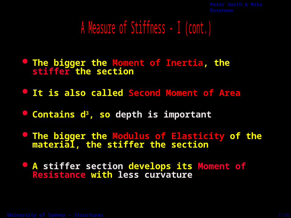
The bigger the Moment of Inertia, the stiffer the section
It is also called Second Moment of Area
Contains d3, so depth is important
The bigger the Modulus of Elasticity of the material, the stiffer the section
A stiffer section develops its Moment of Resistance with less curvature
7/28

University of Sydney – Structures SECTIONS
Peter Smith & Mike Rosenman
Simple solutions for rectangular sections
b
d
Doing the maths (in the Notes)
gives the Section Modulus
For a rectangular section
Zbd2
6mm3
8/28

University of Sydney – Structures SECTIONS
Peter Smith & Mike Rosenman
The bigger the Section Modulus, the stronger the section
Contains d2, so depth is important
9/28

University of Sydney – Structures SECTIONS
Peter Smith & Mike Rosenman
Strength --> Failure of Element
Stiffness --> Amount of Deflection
depth is important
10/28
University of Sydney – Structures SECTIONS
Peter Smith & Mike Rosenman
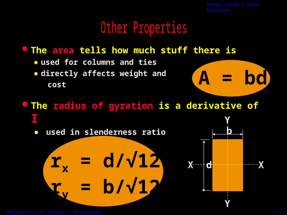
The area tells how much stuff there is● used for columns and ties● directly affects weight and
cost
rx = d/√12ry = b/√12
A = bd The radius of gyration is a derivative of I
● used in slenderness ratio
11/28
Y
b
dX X
Y

University of Sydney – Structures SECTIONS
Peter Smith & Mike Rosenman
Can be calculated, with a little extra work Manufacturers publish tables of properties
12/28

University of Sydney – Structures SECTIONS
Peter Smith & Mike Rosenman
12/28

University of Sydney – Structures SECTIONS
Peter Smith & Mike Rosenman
Checking Beams
Designing Beams
● given the beam section● check that the stresses & deflection
are within the allowable limits
● find the Bending Moment and Shear Force● select a suitable section
13/28

University of Sydney – Structures SECTIONS
Peter Smith & Mike Rosenman
Go back to the bending moment diagrams
Maximum stress occurs where bending moment is a maximum
f =M
Z
M is maximum here
14/28
Bending Moment
Section ModulusStress =

University of Sydney – Structures SECTIONS
Peter Smith & Mike Rosenman
Given the beam size and material
Z = bd2 / 6M = max BM
Actual Stress = M / Z
Allowable Stress (from Code)
b
d
Find the maximum Bending Moment
Use Stress = Moment/Section Modulus Compare this stress to the Code allowable stress
Actual Allowable?<
15/28

University of Sydney – Structures SECTIONS
Peter Smith & Mike Rosenman
Given a softwood timber beam 250 x 50mm
Section Modulus Z = bd2 / 6
Actual Stress f = M / Z
50
250
Given maximum Bending Moment = 4kNm
Given Code allowable stress = 8MPa 4 kNm
= 4 x 103 x 103 / 0.52 x 106
= 50 x 2502 / 6 = 0.52 x 106 mm3
= 7.69 MPa < 8MPa
Actual Stress < Allowable Stress
16/28

University of Sydney – Structures SECTIONS
Peter Smith & Mike Rosenman
Given the maximum Bending Moment Given the Code allowable stress for the material Use Section Modulus = Moment / Stress Look up a table to find a suitable section
b?
d?
M = max BMAllowable Stress (from Code)
required Z = M / Allowable Stress
a) choose b and d to give Z >= than required Z or
b) look up Tables of Properties
17/28

University of Sydney – Structures SECTIONS
Peter Smith & Mike Rosenman
Given the maximum Bending Moment = 4 kNm Given the Code allowable stress for
structural steel = 165 MPa
b?
d?
required Z = 4 x 10⁶ / 165 = 24 x 103 mm3
looking up a catalogue of steel purlins we find C15020 - C-section 150 deep, 2.0mm thickness has a
Z = 27.89 x 103 mm3
(steel handbooks give Z values in 103 mm3)
(smallest section Z >= reqd Z)
18/28

University of Sydney – Structures SECTIONS
Peter Smith & Mike Rosenman
Both E and I come into the deflection formula (Material and Section properties)
Depth, d
Span, L
W
19/28
The load, W, and span, L3
Note that I has a d3 factor
Span-to-depth ratios (L/d) are often used as a guide

University of Sydney – Structures SECTIONS
Peter Smith & Mike Rosenman
20/28
WL3
48EI8d
Central point loadW
L
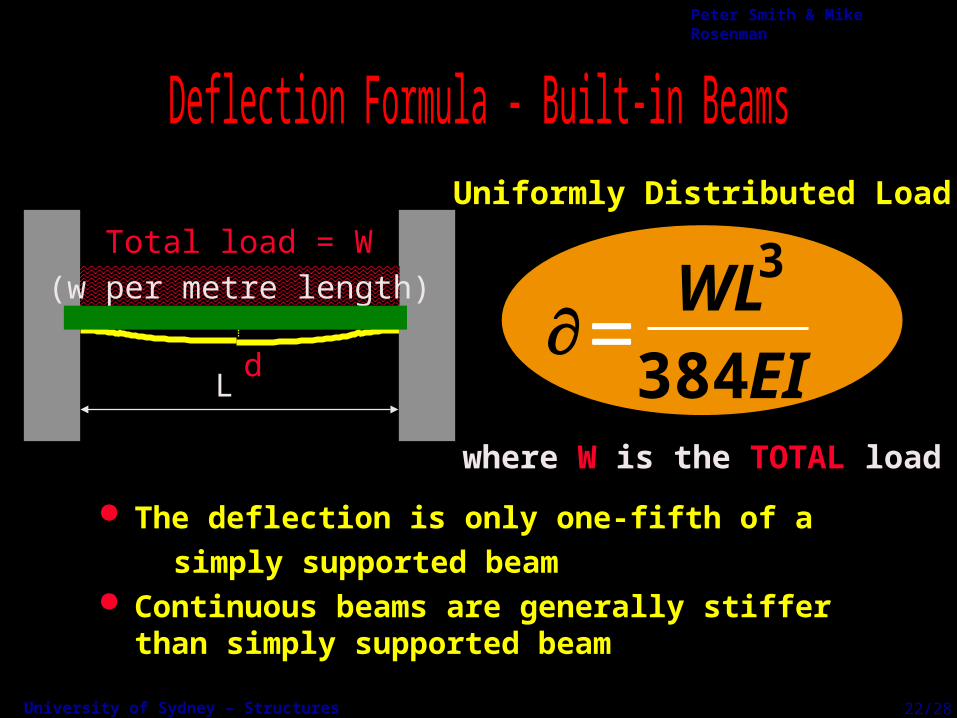
5WL3
384EI5d
Uniformly Distributed Load
where W is the TOTAL load
(w per metre length)
Total load = W
L

University of Sydney – Structures SECTIONS
Peter Smith & Mike Rosenman
W
L
Central point load
WL3
8EI
48d
WL3
3EI
128d
21/28
where W is the TOTAL load
Uniformly Distributed Load(w per metre length)
L
Total load = W
University of Sydney – Structures SECTIONS
Peter Smith & Mike Rosenman
The deflection is only one-fifth of a
simply supported beam Continuous beams are generally stiffer than
simply supported beam
where W is the TOTAL load
WL3
384EId
(w per metre length)
L
Total load = W
Uniformly Distributed Load
22/28

University of Sydney – Structures SECTIONS
Peter Smith & Mike Rosenman
Given load, W, and span, LGiven Modulus of Elasticity, E, and Moment of Inertia, IUse deflection formula to find deflectionBe careful with units (work in N and mm)Compare to Code limit (usually given as L/500, L/250 etc)
23/28
Given the beam size and material
Given the loading conditions
Use formula for maximum deflection
Compare this deflection to the Code allowable deflection
University of Sydney – Structures SECTIONS
Peter Smith & Mike Rosenman
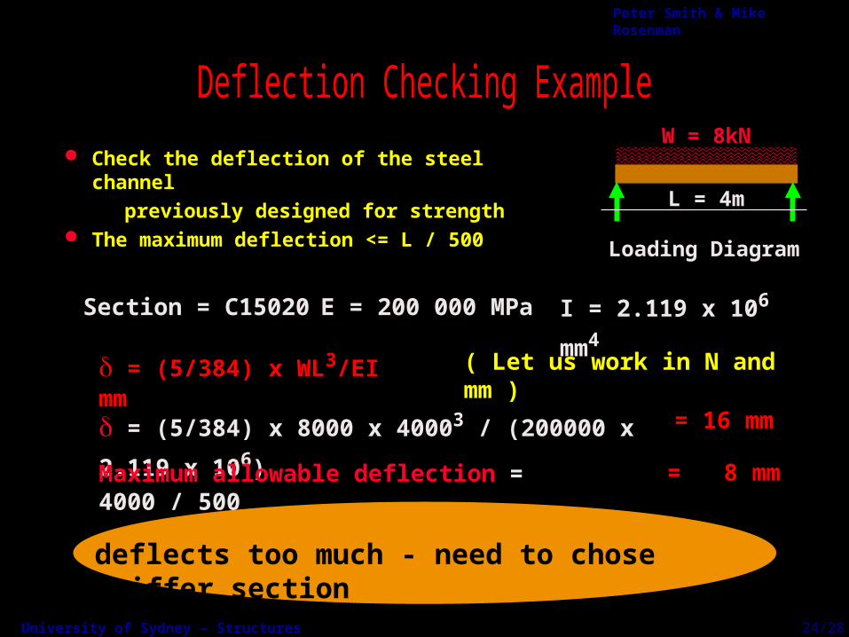
Check the deflection of the steel channel
previously designed for strength The maximum deflection <= L / 500
W = 8kN
L = 4m
Loading Diagram
Section = C15020 E = 200 000 MPa I = 2.119 x 106 mm4
= (5/384) x 8000 x 40003 / (200000 x 2.119 x 106)
= (5/384) x WL3/EI mm ( Let us work in N and mm )
Maximum allowable deflection = 4000 / 500
= 16 mm
= 8 mm
deflects too much - need to chose stiffer section
24/28
University of Sydney – Structures SECTIONS
Peter Smith & Mike Rosenman
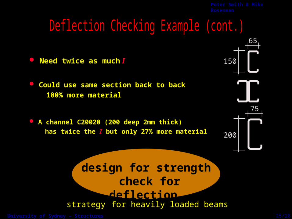
Need twice as much I
design for strength check for deflection
65
150
75
200
Could use same section back to back
100% more material
A channel C20020 (200 deep 2mm thick)
has twice the I but only 27% more material
strategy for heavily loaded beams25/28

University of Sydney – Structures SECTIONS
Peter Smith & Mike Rosenman
Given the loading conditions
Given the Code allowable deflection
Use deflection formula to find I Look up a table to find a suitable section
Given load, W, span, L, and Modulus of Elasticity, EUse the Code limit — e.g., turn L/500 into millimetres
Use deflection formula to find minimum value of ILook up tables or use I = bd3/12 and choose b and d
26/28
University of Sydney – Structures SECTIONS
Peter Smith & Mike Rosenman
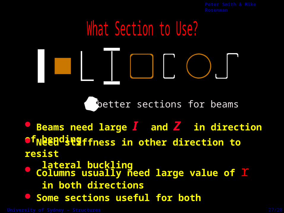
Beams need large I and Z in direction of bending Need stiffness in other direction to resist lateral buckling
Some sections useful for both
Columns usually need large value of r in both directions
= better sections for beams
27/28

University of Sydney – Structures SECTIONS
Peter Smith & Mike Rosenman
Deep beams are economical but subject to lateral buckling
28/28