( 1 ) w a l l s - ijm timber frame part l - supplementary... · acceptable construction details -...
TRANSCRIPT
( 1 ) W A L L S : - I N S U L A T I O N I N C A V I T Y J U L Y 2 0 0 8
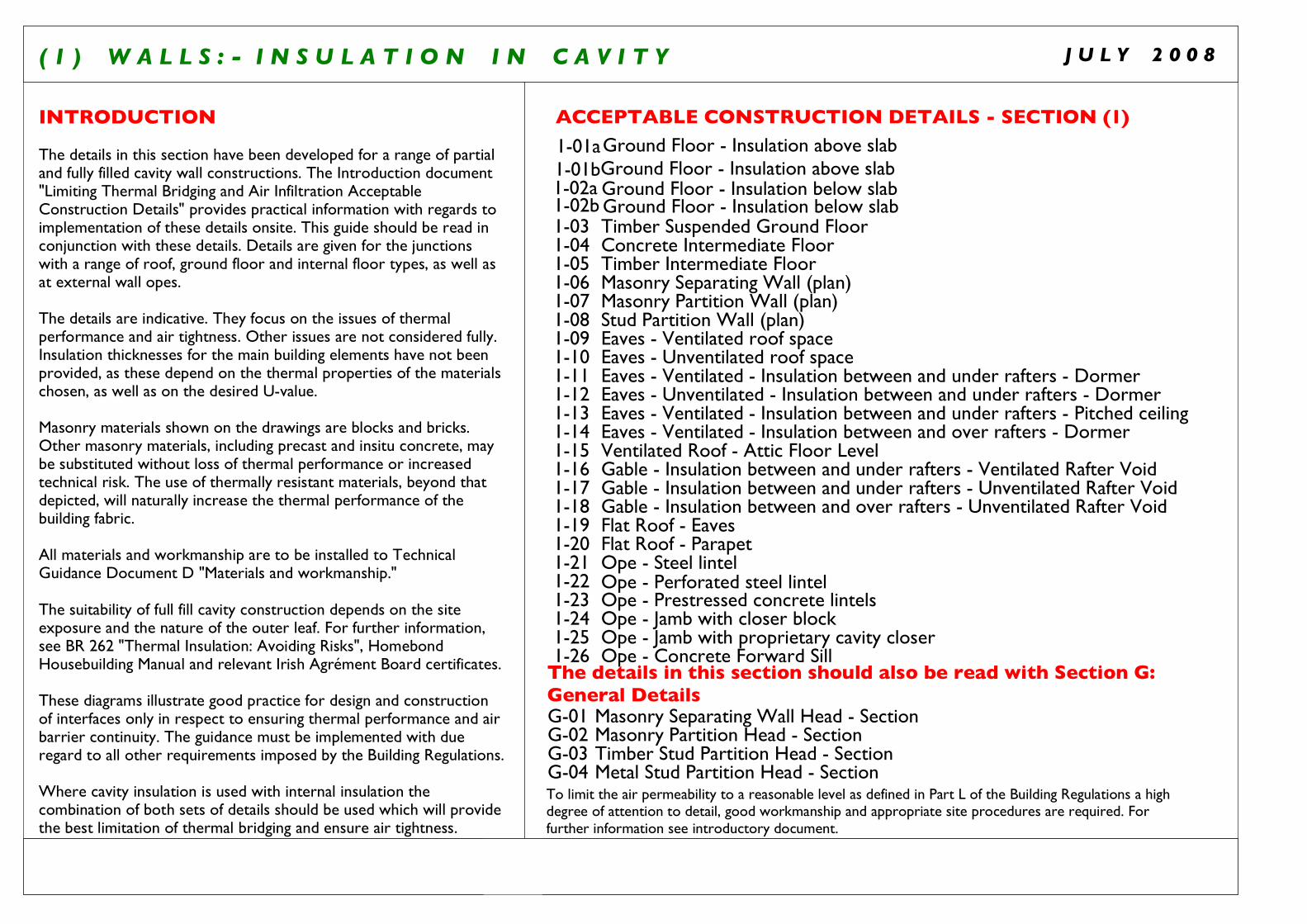
INTRODUCTION
The details in this section have been developed for a range of partial and fully filled cavity wall constructions. The Introduction document "Limiting Thermal Bridging and Air Infiltration Acceptable Construction Details" provides practical information with regards to implementation of these details onsite. This guide should be read in conjunction with these details. Details are given for the junctions with a range of roof, ground floor and internal floor types, as well as at external wall opes.
The details are indicative. They focus on the issues of thermal performance and air tightness. Other issues are not considered fully. Insulation thicknesses for the main building elements have not been provided, as these depend on the thermal properties of the materials chosen, as well as on the desired U-value.
Masonry materials shown on the drawings are blocks and bricks. Other masonry materials, including precast and insitu concrete, may be substituted without loss of thermal performance or increased technical risk. The use of thermally resistant materials, beyond that depicted, will naturally increase the thermal performance of the building fabric.
All materials and workmanship are to be installed to Technical Guidance Document D "Materials and workmanship."
The suitability of full fill cavity construction depends on the site exposure and the nature of the outer leaf. For further information, see BR 262 "Thermal Insulation: Avoiding Risks", Homebond Housebuilding Manual and relevant Irish Agrément Board certificates.
These diagrams illustrate good practice for design and construction of interfaces only in respect to ensuring thermal performance and air barrier continuity. The guidance must be implemented with due regard to all other requirements imposed by the Building Regulations.
Where cavity insulation is used with internal insulation the combination of both sets of details should be used which will provide the best limitation of thermal bridging and ensure air tightness.
ACCEPTABLE CONSTRUCTION DETAILS - SECTION (1)
Timber Suspended Ground Floor Concrete Intermediate Floor Timber Intermediate Floor Masonry Separating Wall (plan)Masonry Partition Wall (plan)Stud Partition Wall (plan)
Ventilated Roof - Attic Floor Level
Eaves - Unventilated roof spaceEaves - Ventilated - Insulation between and under rafters - Dormer
Gable - Insulation between and under rafters - Ventilated Rafter VoidGable - Insulation between and under rafters - Unventilated Rafter Void
Flat Roof - ParapetFlat Roof - Eaves
Ope - Steel lintel
Ope - Prestressed concrete lintelsOpe - Jamb with closer blockOpe - Jamb with proprietary cavity closerOpe - Concrete Forward Sill
Masonry Separating Wall Head - SectionMasonry Partition Head - SectionTimber Stud Partition Head - SectionMetal Stud Partition Head - Section
1-01a
1-02a
1-031-041-051-061-071-081-091-101-11
1-151-161-17
1-191-201-211-221-231-241-25
G-01G-02G-03G-04
Ground Floor - Insulation below slab
Ground Floor - Insulation above slab
Eaves - Ventilated roof space
1-121-13
Eaves - Unventilated - Insulation between and under rafters - DormerEaves - Ventilated - Insulation between and under rafters - Pitched ceiling
1-14
Gable - Insulation between and over rafters - Unventilated Rafter Void1-18
1-26
Eaves - Ventilated - Insulation between and over rafters - Dormer
Ope - Perforated steel lintel
The details in this section should also be read with Section G:General Details
To limit the air permeability to a reasonable level as defined in Part L of the Building Regulations a high degree of attention to detail, good workmanship and appropriate site procedures are required. For further information see introductory document.
1-02b Ground Floor - Insulation below slab
1-01bGround Floor - Insulation above slab
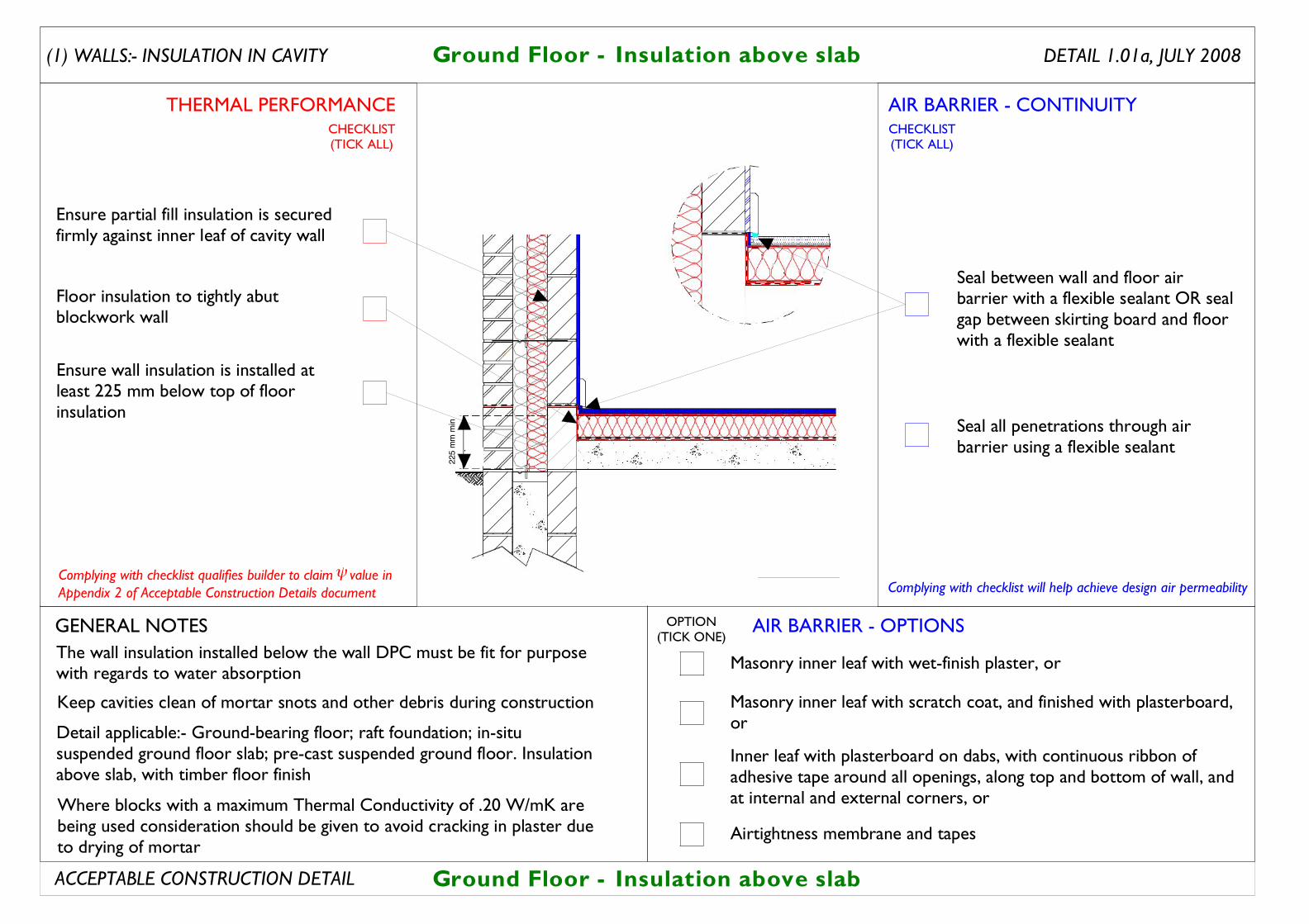
Ensure wall insulation is installed at least 225 mm below top of floor insulation
Ground Floor - Insulation above slab
Seal all penetrations through air barrier using a flexible sealant
The wall insulation installed below the wall DPC must be fit for purpose with regards to water absorption
Floor insulation to tightly abut blockwork wall
Ensure partial fill insulation is secured firmly against inner leaf of cavity wall
Seal between wall and floor air barrier with a flexible sealant OR seal gap between skirting board and floor with a flexible sealant
Ground Floor - Insulation above slab
Detail applicable:- Ground-bearing floor; raft foundation; in-situ suspended ground floor slab; pre-cast suspended ground floor. Insulation above slab, with timber floor finish
Keep cavities clean of mortar snots and other debris during construction
DETAIL 1.01a, JULY 2008
Where blocks with a maximum Thermal Conductivity of .20 W/mK are being used consideration should be given to avoid cracking in plaster due to drying of mortar
AIR BARRIER - CONTINUITY
AIR BARRIER - OPTIONS
THERMAL PERFORMANCE
(1) WALLS:- INSULATION IN CAVITY
Complying with checklist will help achieve design air permeability
GENERAL NOTES
ACCEPTABLE CONSTRUCTION DETAIL
CHECKLIST(TICK ALL)
CHECKLIST(TICK ALL)
OPTION(TICK ONE)
Masonry inner leaf with wet-finish plaster, or
Inner leaf with plasterboard on dabs, with continuous ribbon of adhesive tape around all openings, along top and bottom of wall, and at internal and external corners, or
Masonry inner leaf with scratch coat, and finished with plasterboard, or
Airtightness membrane and tapes
225
mm
min
Complying with checklist qualifies builder to claim value inAppendix 2 of Acceptable Construction Details document
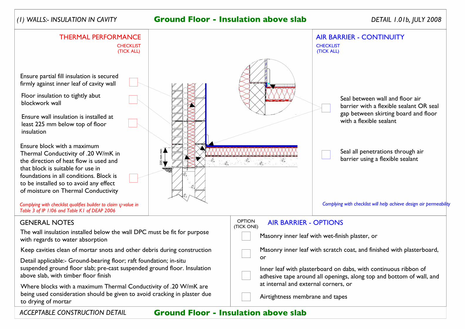
Complying with checklist qualifies builder to claim value in Table 3 of IP 1/06 and Table K1 of DEAP 2006
ψ
Ensure wall insulation is installed at least 225 mm below top of floor insulation
Ground Floor - Insulation above slab
Seal all penetrations through air barrier using a flexible sealant
The wall insulation installed below the wall DPC must be fit for purpose with regards to water absorption
Floor insulation to tightly abut blockwork wall
Ensure partial fill insulation is secured firmly against inner leaf of cavity wall
Seal between wall and floor air barrier with a flexible sealant OR seal gap between skirting board and floor with a flexible sealant
Ground Floor - Insulation above slab
Detail applicable:- Ground-bearing floor; raft foundation; in-situ suspended ground floor slab; pre-cast suspended ground floor. Insulation above slab, with timber floor finish
Keep cavities clean of mortar snots and other debris during construction
DETAIL 1.01b, JULY 2008
Ensure block with a maximum Thermal Conductivity of .20 W/mK in the direction of heat flow is used and that block is suitable for use in foundations in all conditions. Block is to be installed so to avoid any effect of moisture on Thermal Conductivity
Where blocks with a maximum Thermal Conductivity of .20 W/mK are being used consideration should be given to avoid cracking in plaster due to drying of mortar
AIR BARRIER - CONTINUITY
AIR BARRIER - OPTIONS
THERMAL PERFORMANCE
(1) WALLS:- INSULATION IN CAVITY
Complying with checklist will help achieve design air permeability
GENERAL NOTES
ACCEPTABLE CONSTRUCTION DETAIL
CHECKLIST(TICK ALL)
CHECKLIST(TICK ALL)
OPTION(TICK ONE)
Masonry inner leaf with wet-finish plaster, or
Inner leaf with plasterboard on dabs, with continuous ribbon of adhesive tape around all openings, along top and bottom of wall, and at internal and external corners, or
Masonry inner leaf with scratch coat, and finished with plasterboard, or
Airtightness membrane and tapes
225
mm
min
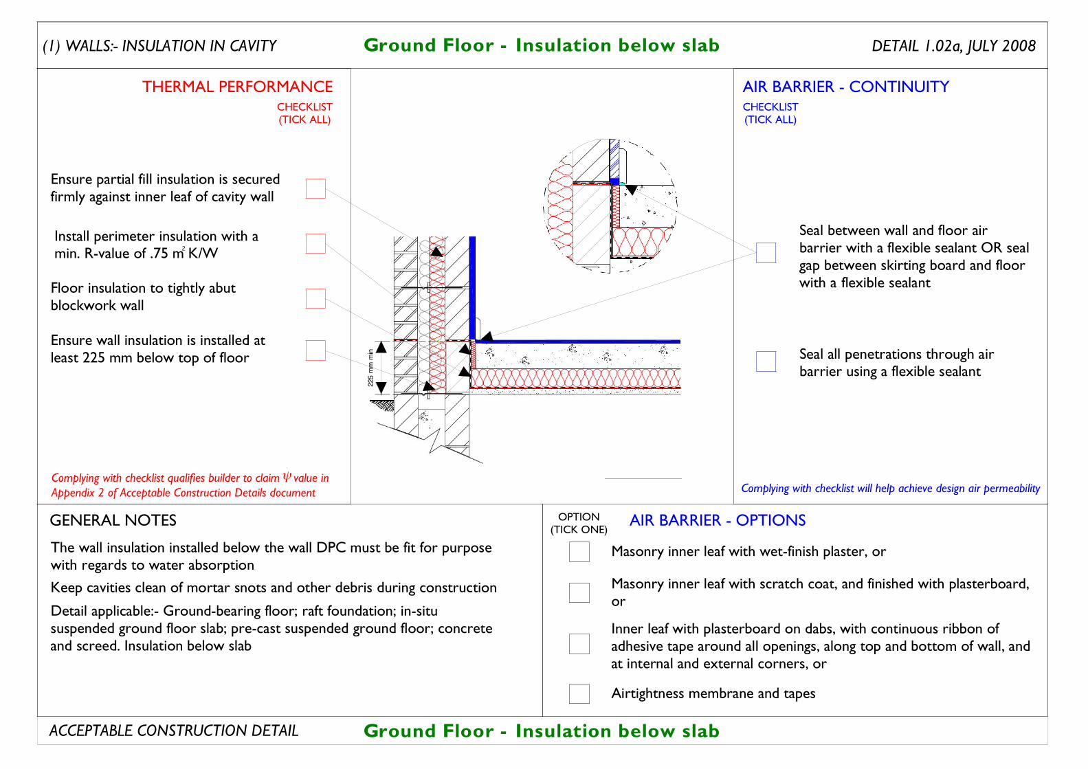
Ensure wall insulation is installed at least 225 mm below top of floor
Floor insulation to tightly abut blockwork wall
Detail applicable:- Ground-bearing floor; raft foundation; in-situ suspended ground floor slab; pre-cast suspended ground floor; concrete and screed. Insulation below slab
Seal all penetrations through air barrier using a flexible sealant
Seal between wall and floor air barrier with a flexible sealant OR seal gap between skirting board and floor with a flexible sealant
Ensure partial fill insulation is secured firmly against inner leaf of cavity wall
Ground Floor - Insulation below slab
Ground Floor - Insulation below slab
DETAIL 1.02a, JULY 2008
The wall insulation installed below the wall DPC must be fit for purpose with regards to water absorption
Keep cavities clean of mortar snots and other debris during construction
AIR BARRIER - CONTINUITY
AIR BARRIER - OPTIONS
THERMAL PERFORMANCE
(1) WALLS:- INSULATION IN CAVITY
GENERAL NOTES
ACCEPTABLE CONSTRUCTION DETAIL
CHECKLIST(TICK ALL)
CHECKLIST(TICK ALL)
OPTION(TICK ONE)
Masonry inner leaf with wet-finish plaster, or
Inner leaf with plasterboard on dabs, with continuous ribbon of adhesive tape around all openings, along top and bottom of wall, and at internal and external corners, or
Masonry inner leaf with scratch coat, and finished with plasterboard, or
Airtightness membrane and tapes
225
mm
min
Install perimeter insulation with a min. R-value of .75 m K/W2
Complying with checklist will help achieve design air permeabilityComplying with checklist qualifies builder to claim value inAppendix 2 of Acceptable Construction Details document

Complying with checklist qualifies builder to claim value in Table 3 of IP 1/06 and Table K1 of DEAP 2006
ψ
Ensure wall insulation is installed at least 225 mm below top of floor
Floor insulation to tightly abut blockwork wall
Detail applicable:- Ground-bearing floor; raft foundation; in-situ suspended ground floor slab; pre-cast suspended ground floor; concrete and screed. Insulation below slab
Seal all penetrations through air barrier using a flexible sealant
Seal between wall and floor air barrier with a flexible sealant OR seal gap between skirting board and floor with a flexible sealant
Ensure partial fill insulation is secured firmly against inner leaf of cavity wall
Ground Floor - Insulation below slab
Ground Floor - Insulation below slab
DETAIL 1.02b, JULY 2008
The wall insulation installed below the wall DPC must be fit for purpose with regards to water absorption
Keep cavities clean of mortar snots and other debris during construction
AIR BARRIER - CONTINUITY
AIR BARRIER - OPTIONS
THERMAL PERFORMANCE
(1) WALLS:- INSULATION IN CAVITY
Complying with checklist will help achieve design air permeability
GENERAL NOTES
ACCEPTABLE CONSTRUCTION DETAIL
CHECKLIST(TICK ALL)
CHECKLIST(TICK ALL)
OPTION(TICK ONE)
Masonry inner leaf with wet-finish plaster, or
Inner leaf with plasterboard on dabs, with continuous ribbon of adhesive tape around all openings, along top and bottom of wall, and at internal and external corners, or
Masonry inner leaf with scratch coat, and finished with plasterboard, or
Airtightness membrane and tapes
2 25
mm
min
Install perimeter insulation with a min. R-value of .75 m K/W2
Ensure block with a maximum Thermal Conductivity of .20 W/mK in the direction of heat flow is used and that block is suitable for use in foundations in all conditions. Block is to be installed so to avoid any effect of moisture on thermal conductivity.
Complying with checklist qualifies builder to claim value in Table 3 of IP 1/06 and Table K1 of DEAP 2006
!
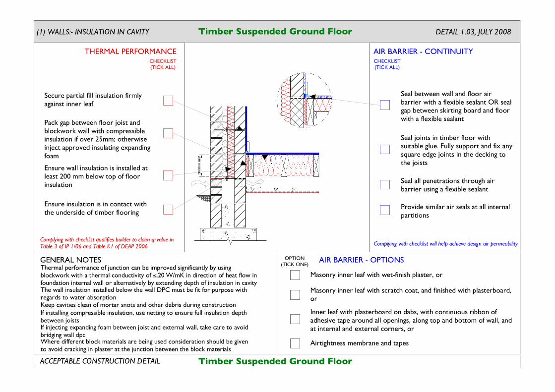
If injecting expanding foam between joist and external wall, take care to avoid bridging wall dpc
If installing compressible insulation, use netting to ensure full insulation depth between joists
Timber Suspended Ground Floor
Timber Suspended Ground Floor
DETAIL 1.03, JULY 2008
Seal all penetrations through air barrier using a flexible sealant
Seal between wall and floor air barrier with a flexible sealant OR seal gap between skirting board and floor with a flexible sealant
Provide similar air seals at all internal partitions
Seal joints in timber floor with suitable glue. Fully support and fix any square edge joints in the decking to the joists
Secure partial fill insulation firmly against inner leaf
Ensure wall insulation is installed at least 200 mm below top of floor insulation
Pack gap between floor joist and blockwork wall with compressible insulation if over 25mm; otherwise inject approved insulating expanding foam
Ensure insulation is in contact with the underside of timber flooring
The wall insulation installed below the wall DPC must be fit for purpose with regards to water absorptionKeep cavities clean of mortar snots and other debris during construction
Thermal performance of junction can be improved significantly by using blockwork with a thermal conductivity of ".20 W/mK in direction of heat flow in foundation internal wall or alternatively by extending depth of insulation in cavity
Where different block materials are being used consideration should be given to avoid cracking in plaster at the junction between the block materials
AIR BARRIER - CONTINUITY
AIR BARRIER - OPTIONS
THERMAL PERFORMANCE
(1) WALLS:- INSULATION IN CAVITY
Complying with checklist will help achieve design air permeability
GENERAL NOTES
ACCEPTABLE CONSTRUCTION DETAIL
CHECKLIST(TICK ALL)
CHECKLIST(TICK ALL)
OPTION(TICK ONE)
Masonry inner leaf with wet-finish plaster, or
Inner leaf with plasterboard on dabs, with continuous ribbon of adhesive tape around all openings, along top and bottom of wall, and at internal and external corners, or
Masonry inner leaf with scratch coat, and finished with plasterboard, or
Airtightness membrane and tapes
Complying with checklist qualifies builder to claim value in Table 3 of IP 1/06 and Table K1 of DEAP 2006
!
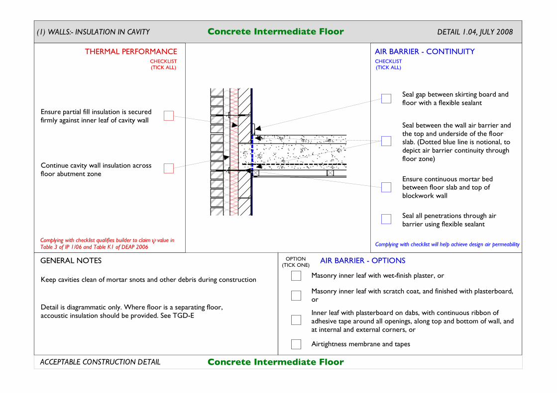
Seal gap between skirting board and floor with a flexible sealant
Seal between the wall air barrier and the top and underside of the floor slab. (Dotted blue line is notional, to depict air barrier continuity through floor zone)
Seal all penetrations through air barrier using flexible sealant
Keep cavities clean of mortar snots and other debris during construction
Ensure partial fill insulation is secured firmly against inner leaf of cavity wall
Continue cavity wall insulation across floor abutment zone
Ensure continuous mortar bed between floor slab and top of blockwork wall
Detail is diagrammatic only. Where floor is a separating floor, accoustic insulation should be provided. See TGD-E
DETAIL 1.04, JULY 2008Concrete Intermediate Floor
Concrete Intermediate Floor
AIR BARRIER - CONTINUITY
AIR BARRIER - OPTIONS
THERMAL PERFORMANCE
(1) WALLS:- INSULATION IN CAVITY
Complying with checklist will help achieve design air permeability
GENERAL NOTES
ACCEPTABLE CONSTRUCTION DETAIL
CHECKLIST(TICK ALL)
CHECKLIST(TICK ALL)
OPTION(TICK ONE)
Masonry inner leaf with wet-finish plaster, or
Inner leaf with plasterboard on dabs, with continuous ribbon of adhesive tape around all openings, along top and bottom of wall, and at internal and external corners, or
Masonry inner leaf with scratch coat, and finished with plasterboard, or
Airtightness membrane and tapes
Complying with checklist qualifies builder to claim value in Table 3 of IP 1/06 and Table K1 of DEAP 2006
!
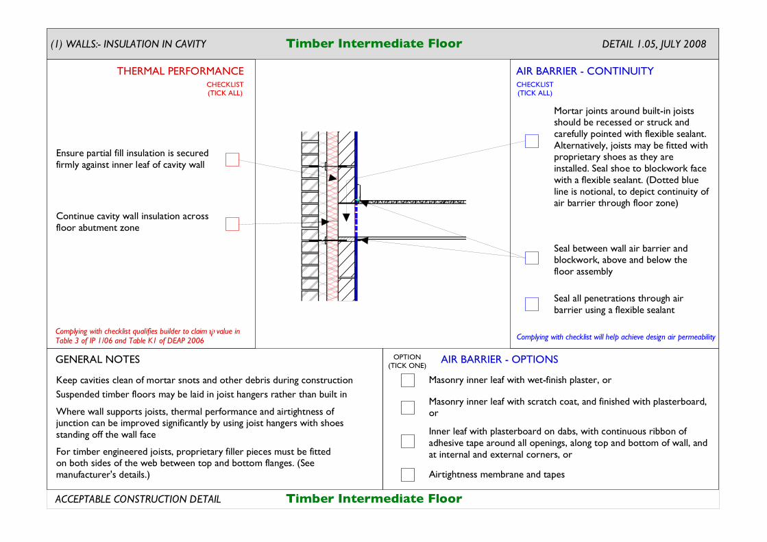
Mortar joints around built-in joists should be recessed or struck and carefully pointed with flexible sealant. Alternatively, joists may be fitted with proprietary shoes as they are installed. Seal shoe to blockwork face with a flexible sealant. (Dotted blue line is notional, to depict continuity of air barrier through floor zone)
DETAIL 1.05, JULY 2008
Keep cavities clean of mortar snots and other debris during construction
For timber engineered joists, proprietary filler pieces must be fitted on both sides of the web between top and bottom flanges. (See manufacturer's details.)
Suspended timber floors may be laid in joist hangers rather than built in
Ensure partial fill insulation is secured firmly against inner leaf of cavity wall
Continue cavity wall insulation across floor abutment zone
Seal all penetrations through air barrier using a flexible sealant
Seal between wall air barrier and blockwork, above and below the floor assembly
Timber Intermediate Floor
Timber Intermediate Floor
Where wall supports joists, thermal performance and airtightness of junction can be improved significantly by using joist hangers with shoes standing off the wall face
AIR BARRIER - CONTINUITY
AIR BARRIER - OPTIONS
THERMAL PERFORMANCE
(1) WALLS:- INSULATION IN CAVITY
Complying with checklist will help achieve design air permeability
GENERAL NOTES
ACCEPTABLE CONSTRUCTION DETAIL
CHECKLIST(TICK ALL)
CHECKLIST(TICK ALL)
OPTION(TICK ONE)
Masonry inner leaf with wet-finish plaster, or
Inner leaf with plasterboard on dabs, with continuous ribbon of adhesive tape around all openings, along top and bottom of wall, and at internal and external corners, or
Masonry inner leaf with scratch coat, and finished with plasterboard, or
Airtightness membrane and tapes
Complying with checklist qualifies builder to claim value in Table 3 of IP 1/06 and Table K1 of DEAP 2006
!
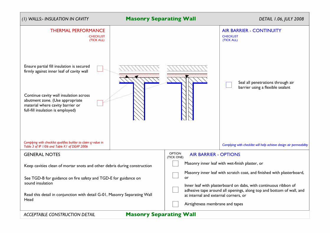
Ensure partial fill insulation is secured firmly against inner leaf of cavity wall
Continue cavity wall insulation across abutment zone. (Use appropriate material where cavity barrier or full-fill insulation is employed)
Seal all penetrations through air barrier using a flexible sealant
Keep cavities clean of mortar snots and other debris during construction
Read this detail in conjunction with detail G-01, Masonry Separating Wall Head
Masonry Separating Wall
Masonry Separating Wall
DETAIL 1.06, JULY 2008
See TGD-B for guidance on fire safety and TGD-E for guidance on sound insulation
AIR BARRIER - CONTINUITY
AIR BARRIER - OPTIONS
THERMAL PERFORMANCE
(1) WALLS:- INSULATION IN CAVITY
Complying with checklist will help achieve design air permeability
GENERAL NOTES
ACCEPTABLE CONSTRUCTION DETAIL
CHECKLIST(TICK ALL)
CHECKLIST(TICK ALL)
OPTION(TICK ONE)
Masonry inner leaf with wet-finish plaster, or
Inner leaf with plasterboard on dabs, with continuous ribbon of adhesive tape around all openings, along top and bottom of wall, and at internal and external corners, or
Masonry inner leaf with scratch coat, and finished with plasterboard, or
Airtightness membrane and tapes

Complying with checklist qualifies builder to claim value in Table 3 of IP 1/06 and Table K1 of DEAP 2006
!
DETAIL 1.07, JULY 2008
Keep cavities clean of mortar snots and other debris during construction
Read this detail in conjunction with detail G-02, Blockwork Partition Head
Masonry Partition Wall
Ensure partial fill insulation is secured firmly against inner leaf of cavity wall
Continue cavity wall insulation across abutment zone
Seal all penetrations through air barrier using a flexible sealant
Seal between air barrier on external wall and the blockwork, to the partition wall. (Dotted blue line is notional, to depict air barrier continuity through partition, depending on whether partition toothed into external wall or braced with ties)
Masonry Partition Wall
AIR BARRIER - CONTINUITY
AIR BARRIER - OPTIONS
THERMAL PERFORMANCE
(1) WALLS:- INSULATION IN CAVITY
Complying with checklist will help achieve design air permeability
GENERAL NOTES
ACCEPTABLE CONSTRUCTION DETAIL
CHECKLIST(TICK ALL)
CHECKLIST(TICK ALL)
OPTION(TICK ONE)
Masonry inner leaf with wet-finish plaster, or
Inner leaf with plasterboard on dabs, with continuous ribbon of adhesive tape around all openings, along top and bottom of wall, and at internal and external corners, or
Masonry inner leaf with scratch coat, and finished with plasterboard, or
Airtightness membrane and tapes
Complying with checklist qualifies builder to claim value in Table 3 of IP 1/06 and Table K1 of DEAP 2006
!
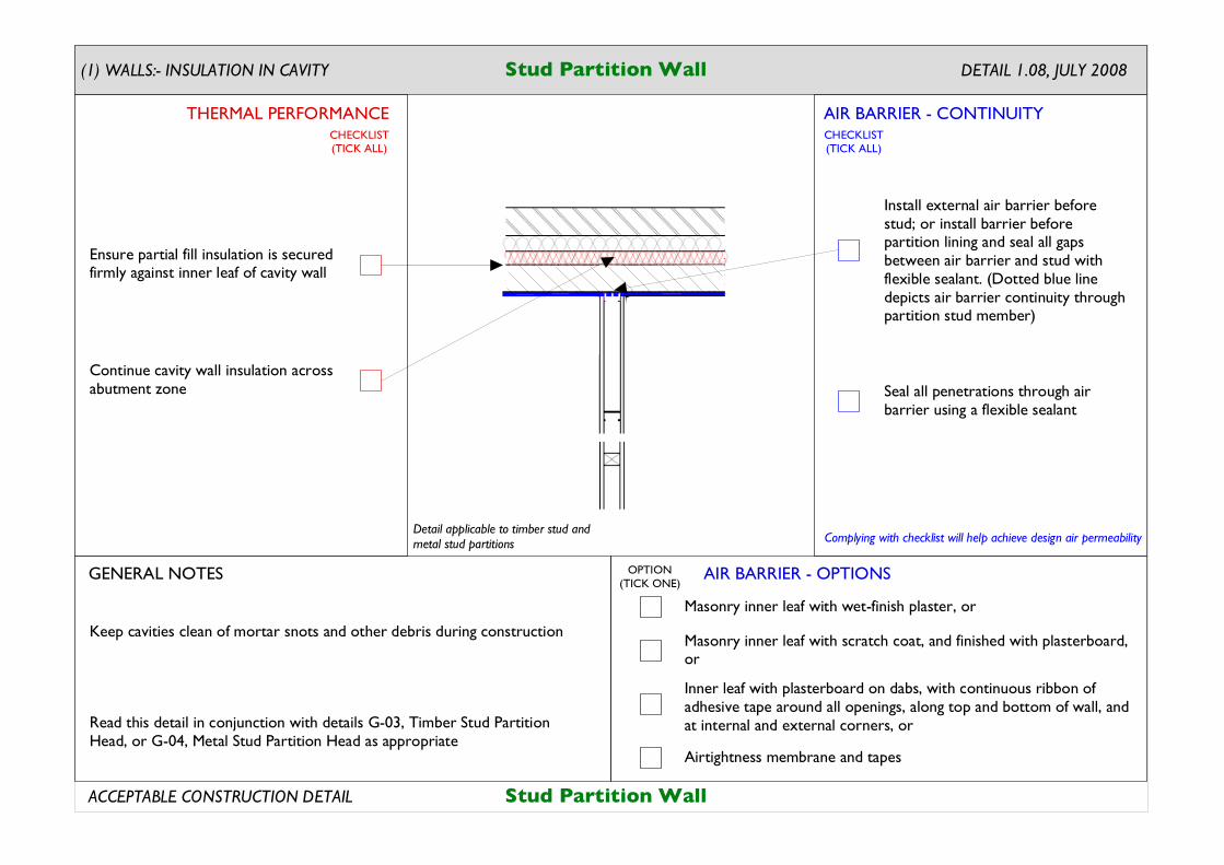
DETAIL 1.08, JULY 2008Stud Partition Wall
Read this detail in conjunction with details G-03, Timber Stud Partition Head, or G-04, Metal Stud Partition Head as appropriate
Ensure partial fill insulation is secured firmly against inner leaf of cavity wall
Continue cavity wall insulation across abutment zone
Keep cavities clean of mortar snots and other debris during construction
Seal all penetrations through air barrier using a flexible sealant
Install external air barrier before stud; or install barrier before partition lining and seal all gaps between air barrier and stud with flexible sealant. (Dotted blue line depicts air barrier continuity through partition stud member)
Detail applicable to timber stud and metal stud partitions
Stud Partition Wall
AIR BARRIER - CONTINUITY
AIR BARRIER - OPTIONS
THERMAL PERFORMANCE
(1) WALLS:- INSULATION IN CAVITY
Complying with checklist will help achieve design air permeability
GENERAL NOTES
ACCEPTABLE CONSTRUCTION DETAIL
CHECKLIST(TICK ALL)
CHECKLIST(TICK ALL)
OPTION(TICK ONE)
Masonry inner leaf with wet-finish plaster, or
Inner leaf with plasterboard on dabs, with continuous ribbon of adhesive tape around all openings, along top and bottom of wall, and at internal and external corners, or
Masonry inner leaf with scratch coat, and finished with plasterboard, or
Airtightness membrane and tapes
Complying with checklist qualifies builder to claim value in Table 3 of IP 1/06 and Table K1 of DEAP 2006
ψ
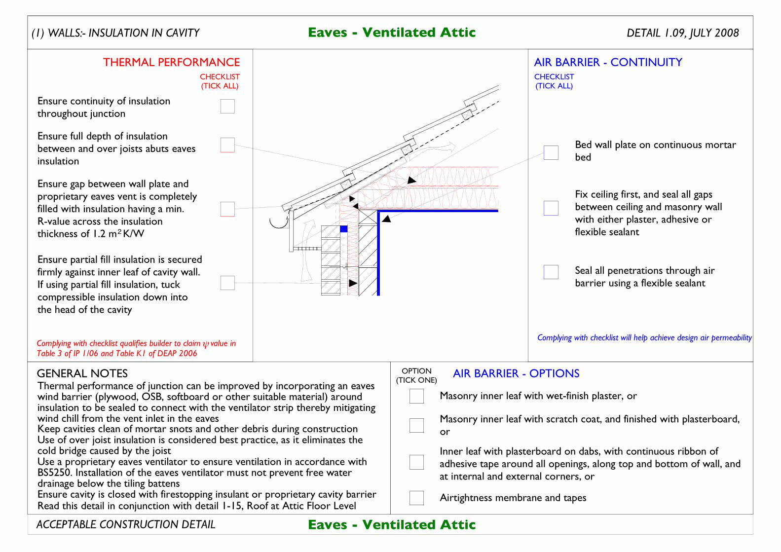
Thermal performance of junction can be improved by incorporating an eaves wind barrier (plywood, OSB, softboard or other suitable material) around insulation to be sealed to connect with the ventilator strip thereby mitigating wind chill from the vent inlet in the eavesKeep cavities clean of mortar snots and other debris during constructionUse of over joist insulation is considered best practice, as it eliminates the cold bridge caused by the joistUse a proprietary eaves ventilator to ensure ventilation in accordance with BS5250. Installation of the eaves ventilator must not prevent free water drainage below the tiling battens
Ensure partial fill insulation is secured firmly against inner leaf of cavity wall. If using partial fill insulation, tuck compressible insulation down into the head of the cavity
Ensure continuity of insulation throughout junction
Ensure full depth of insulation between and over joists abuts eaves insulation
Bed wall plate on continuous mortar bed
Fix ceiling first, and seal all gaps between ceiling and masonry wall with either plaster, adhesive or flexible sealant
Seal all penetrations through air barrier using a flexible sealant
Eaves - Ventilated Attic
Ensure gap between wall plate and proprietary eaves vent is completely filled with insulation having a min. R-value across the insulation thickness of 1.2 m K/W2
Ensure cavity is closed with firestopping insulant or proprietary cavity barrierRead this detail in conjunction with detail 1-15, Roof at Attic Floor Level
AIR BARRIER - CONTINUITY
AIR BARRIER - OPTIONS
THERMAL PERFORMANCE
Complying with checklist will help achieve design air permeability
GENERAL NOTES
ACCEPTABLE CONSTRUCTION DETAIL
CHECKLIST(TICK ALL)
CHECKLIST(TICK ALL)
OPTION(TICK ONE)
Masonry inner leaf with wet-finish plaster, or
Inner leaf with plasterboard on dabs, with continuous ribbon of adhesive tape around all openings, along top and bottom of wall, and at internal and external corners, or
Masonry inner leaf with scratch coat, and finished with plasterboard, or
Airtightness membrane and tapes
DETAIL 1.09, JULY 2008Eaves - Ventilated Attic(1) WALLS:- INSULATION IN CAVITY
Complying with checklist qualifies builder to claim value in Table 3 of IP 1/06 and Table K1 of DEAP 2006
ψ
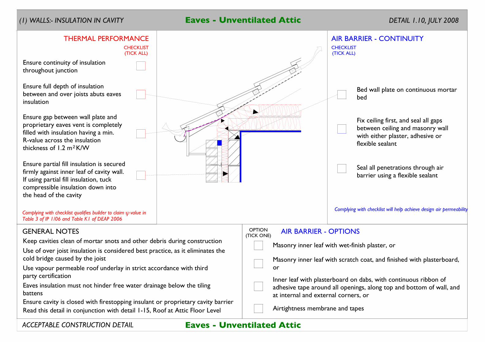
Eaves insulation must not hinder free water drainage below the tiling battens
Eaves - Unventilated Attic
Keep cavities clean of mortar snots and other debris during construction
Use of over joist insulation is considered best practice, as it eliminates the cold bridge caused by the joist
Read this detail in conjunction with detail 1-15, Roof at Attic Floor Level
Use vapour permeable roof underlay in strict accordance with third party certification
Ensure partial fill insulation is secured firmly against inner leaf of cavity wall. If using partial fill insulation, tuck compressible insulation down into the head of the cavity
Ensure continuity of insulation throughout junction
Ensure full depth of insulation between and over joists abuts eaves insulation
Ensure gap between wall plate and proprietary eaves vent is completely filled with insulation having a min. R-value across the insulation thickness of 1.2 m K/W2
Bed wall plate on continuous mortar bed
Fix ceiling first, and seal all gaps between ceiling and masonry wall with either plaster, adhesive or flexible sealant
Seal all penetrations through air barrier using a flexible sealant
Ensure cavity is closed with firestopping insulant or proprietary cavity barrier
AIR BARRIER - CONTINUITY
AIR BARRIER - OPTIONS
THERMAL PERFORMANCE
Complying with checklist will help achieve design air permeability
GENERAL NOTES
ACCEPTABLE CONSTRUCTION DETAIL
CHECKLIST(TICK ALL)
CHECKLIST(TICK ALL)
OPTION(TICK ONE)
Masonry inner leaf with wet-finish plaster, or
Inner leaf with plasterboard on dabs, with continuous ribbon of adhesive tape around all openings, along top and bottom of wall, and at internal and external corners, or
Masonry inner leaf with scratch coat, and finished with plasterboard, or
Airtightness membrane and tapes
(1) WALLS:- INSULATION IN CAVITY Eaves - Unventilated Attic DETAIL 1.10, JULY 2008
Complying with checklist qualifies builder to claim value in Table 3 of IP 1/06 and Table K1 of DEAP 2006
ψ
Ensure cavity is closed with firestopping insulant or proprietary cavity barrier
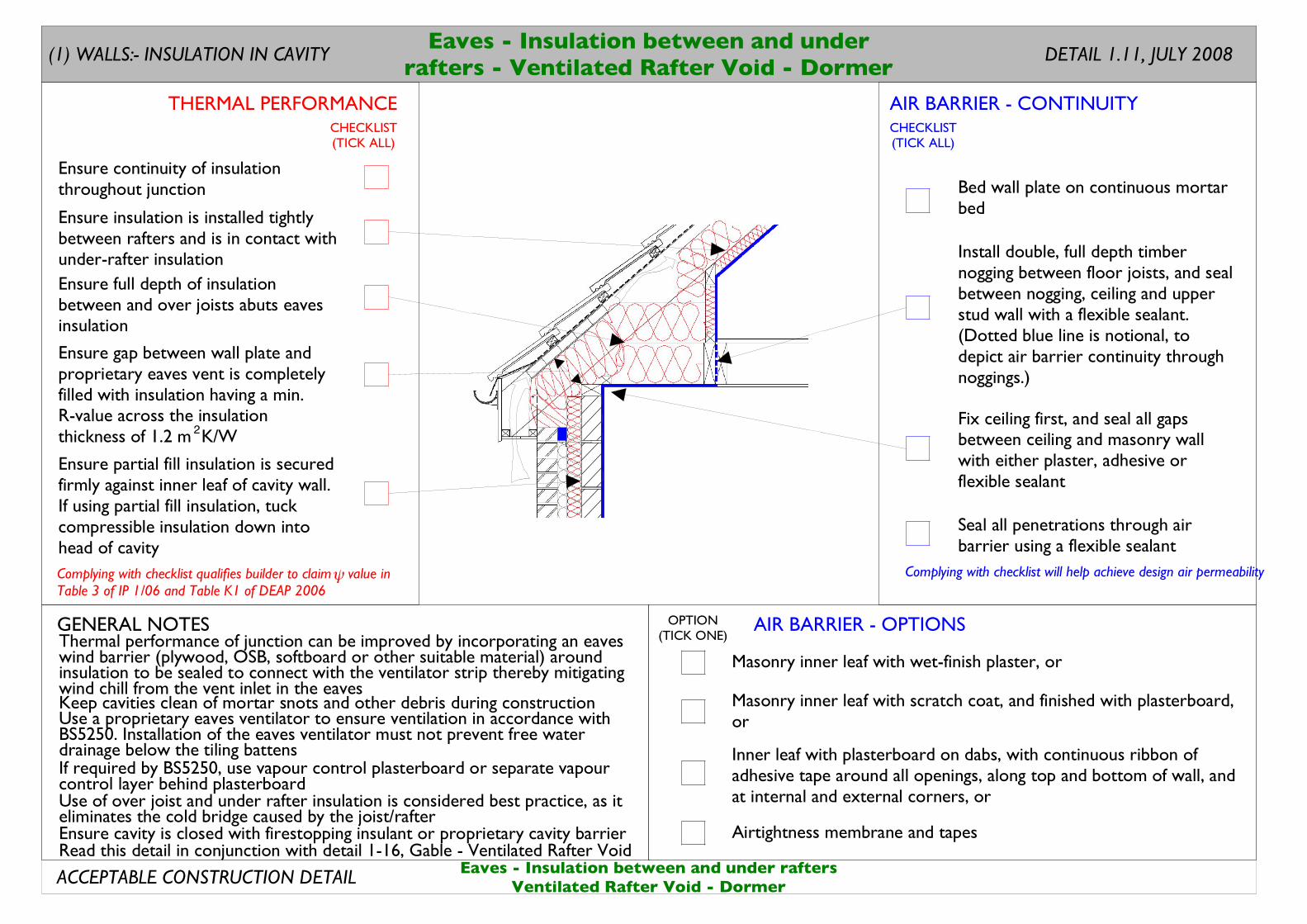
Thermal performance of junction can be improved by incorporating an eaves wind barrier (plywood, OSB, softboard or other suitable material) around insulation to be sealed to connect with the ventilator strip thereby mitigating wind chill from the vent inlet in the eaves
Install double, full depth timber nogging between floor joists, and seal between nogging, ceiling and upper stud wall with a flexible sealant. (Dotted blue line is notional, to depict air barrier continuity through noggings.)
Fix ceiling first, and seal all gaps between ceiling and masonry wall with either plaster, adhesive or flexible sealant
Use a proprietary eaves ventilator to ensure ventilation in accordance with BS5250. Installation of the eaves ventilator must not prevent free water drainage below the tiling battensIf required by BS5250, use vapour control plasterboard or separate vapour control layer behind plasterboard
Keep cavities clean of mortar snots and other debris during construction
Use of over joist and under rafter insulation is considered best practice, as it eliminates the cold bridge caused by the joist/rafter
Read this detail in conjunction with detail 1-16, Gable - Ventilated Rafter Void
Ensure partial fill insulation is secured firmly against inner leaf of cavity wall. If using partial fill insulation, tuck compressible insulation down into head of cavity
Ensure continuity of insulation throughout junction
Ensure full depth of insulation between and over joists abuts eaves insulation
Ensure insulation is installed tightly between rafters and is in contact with under-rafter insulation
Bed wall plate on continuous mortar bed
Seal all penetrations through air barrier using a flexible sealant
Eaves - Insulation between and under raftersVentilated Rafter Void - Dormer
Ensure gap between wall plate and proprietary eaves vent is completely filled with insulation having a min. R-value across the insulation thickness of 1.2 m K/W2
AIR BARRIER - CONTINUITY
AIR BARRIER - OPTIONS
THERMAL PERFORMANCE
Complying with checklist will help achieve design air permeability
GENERAL NOTES
ACCEPTABLE CONSTRUCTION DETAIL
CHECKLIST(TICK ALL)
CHECKLIST(TICK ALL)
OPTION(TICK ONE)
Masonry inner leaf with wet-finish plaster, or
Inner leaf with plasterboard on dabs, with continuous ribbon of adhesive tape around all openings, along top and bottom of wall, and at internal and external corners, or
Masonry inner leaf with scratch coat, and finished with plasterboard, or
Airtightness membrane and tapes
Eaves - Insulation between and underrafters - Ventilated Rafter Void - Dormer
(1) WALLS:- INSULATION IN CAVITY DETAIL 1.11, JULY 2008
Complying with checklist qualifies builder to claim value in Table 3 of IP 1/06 and Table K1 of DEAP 2006
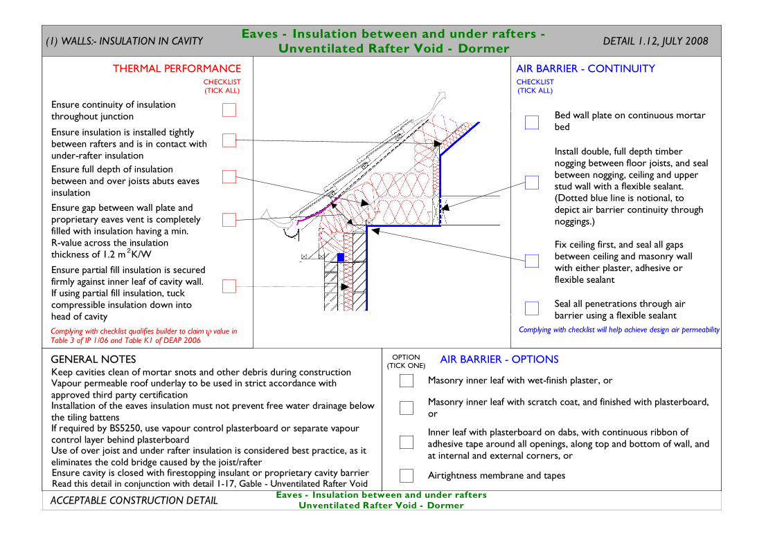
Vapour permeable roof underlay to be used in strict accordance with approved third party certification
If required by BS5250, use vapour control plasterboard or separate vapour control layer behind plasterboard
Keep cavities clean of mortar snots and other debris during construction
Use of over joist and under rafter insulation is considered best practice, as it eliminates the cold bridge caused by the joist/rafter
Read this detail in conjunction with detail 1-17, Gable - Unventilated Rafter Void
Installation of the eaves insulation must not prevent free water drainage below the tiling battens
Install double, full depth timber nogging between floor joists, and seal between nogging, ceiling and upper stud wall with a flexible sealant. (Dotted blue line is notional, to depict air barrier continuity through noggings.)
Fix ceiling first, and seal all gaps between ceiling and masonry wall with either plaster, adhesive or flexible sealant
Ensure partial fill insulation is secured firmly against inner leaf of cavity wall. If using partial fill insulation, tuck compressible insulation down into head of cavity
Ensure continuity of insulation throughout junction
Ensure full depth of insulation between and over joists abuts eaves insulation
Ensure insulation is installed tightly between rafters and is in contact with under-rafter insulation
Bed wall plate on continuous mortar bed
Seal all penetrations through air barrier using a flexible sealant
Ensure gap between wall plate and proprietary eaves vent is completely filled with insulation having a min. R-value across the insulation thickness of 1.2 m K/W2
Eaves - Insulation between and under raftersUnventilated Rafter Void - Dormer
Ensure cavity is closed with firestopping insulant or proprietary cavity barrier
AIR BARRIER - CONTINUITY
AIR BARRIER - OPTIONS
THERMAL PERFORMANCE
Complying with checklist will help achieve design air permeability
GENERAL NOTES
ACCEPTABLE CONSTRUCTION DETAIL
CHECKLIST(TICK ALL)
CHECKLIST(TICK ALL)
OPTION(TICK ONE)
Masonry inner leaf with wet-finish plaster, or
Inner leaf with plasterboard on dabs, with continuous ribbon of adhesive tape around all openings, along top and bottom of wall, and at internal and external corners, or
Masonry inner leaf with scratch coat, and finished with plasterboard, or
Airtightness membrane and tapes
DETAIL 1.12, JULY 2008Eaves - Insulation between and under rafters -
Unventilated Rafter Void - Dormer(1) WALLS:- INSULATION IN CAVITY
Complying with checklist qualifies builder to claim value in Table 3 of IP 1/06 and Table K1 of DEAP 2006
ψ
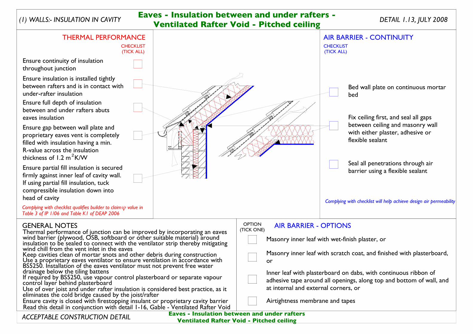
Thermal performance of junction can be improved by incorporating an eaves wind barrier (plywood, OSB, softboard or other suitable material) around insulation to be sealed to connect with the ventilator strip thereby mitigating wind chill from the vent inlet in the eaves
DETAIL 1.13, JULY 2008Eaves - Insulation between and under rafters -
Ventilated Rafter Void - Pitched ceiling
Use a proprietary eaves ventilator to ensure ventilation in accordance with BS5250. Installation of the eaves ventilator must not prevent free water drainage below the tiling battensIf required by BS5250, use vapour control plasterboard or separate vapour control layer behind plasterboard
Keep cavities clean of mortar snots and other debris during construction
Use of over joist and under rafter insulation is considered best practice, as it eliminates the cold bridge caused by the joist/rafter
Read this detail in conjunction with detail 1-16, Gable - Ventilated Rafter Void
Bed wall plate on continuous mortar bed
Fix ceiling first, and seal all gaps between ceiling and masonry wall with either plaster, adhesive or flexible sealant
Seal all penetrations through air barrier using a flexible sealantEnsure partial fill insulation is secured
firmly against inner leaf of cavity wall. If using partial fill insulation, tuck compressible insulation down into head of cavity
Ensure continuity of insulation throughout junction
Ensure full depth of insulation between and under rafters abuts eaves insulation
Ensure insulation is installed tightly between rafters and is in contact with under-rafter insulation
Ensure gap between wall plate and proprietary eaves vent is completely filled with insulation having a min. R-value across the insulation thickness of 1.2 m K/W2
Eaves - Insulation between and under raftersVentilated Rafter Void - Pitched ceiling
Ensure cavity is closed with firestopping insulant or proprietary cavity barrier
AIR BARRIER - CONTINUITY
AIR BARRIER - OPTIONS
THERMAL PERFORMANCE
(1) WALLS:- INSULATION IN CAVITY
Complying with checklist will help achieve design air permeability
GENERAL NOTES
ACCEPTABLE CONSTRUCTION DETAIL
CHECKLIST(TICK ALL)
CHECKLIST(TICK ALL)
OPTION(TICK ONE)
Masonry inner leaf with wet-finish plaster, or
Inner leaf with plasterboard on dabs, with continuous ribbon of adhesive tape around all openings, along top and bottom of wall, and at internal and external corners, or
Masonry inner leaf with scratch coat, and finished with plasterboard, or
Airtightness membrane and tapes
Complying with checklist qualifies builder to claim value in Table 3 of IP 1/06 and Table K1 of DEAP 2006
ψ
DETAIL 1.14, JULY 2008Eaves - Insulation between and over rafters -
Unventilated Rafter Void - Dormer
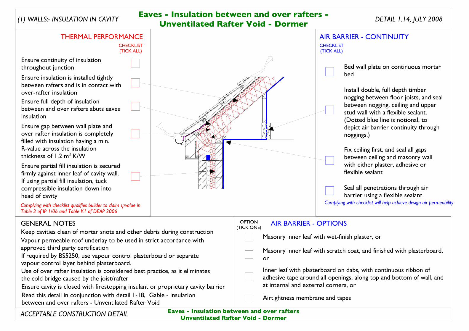
Vapour permeable roof underlay to be used in strict accordance with approved third party certificationIf required by BS5250, use vapour control plasterboard or separate vapour control layer behind plasterboard.
Keep cavities clean of mortar snots and other debris during construction
Use of over rafter insulation is considered best practice, as it eliminates the cold bridge caused by the joist/rafter
Read this detail in conjunction with detail 1-18, Gable - Insulation between and over rafters - Unventilated Rafter Void
Ensure partial fill insulation is secured firmly against inner leaf of cavity wall. If using partial fill insulation, tuck compressible insulation down into head of cavity
Ensure continuity of insulation throughout junction
Ensure full depth of insulation between and over rafters abuts eaves insulation
Ensure insulation is installed tightly between rafters and is in contact with over-rafter insulation Install double, full depth timber
nogging between floor joists, and seal between nogging, ceiling and upper stud wall with a flexible sealant. (Dotted blue line is notional, to depict air barrier continuity through noggings.)
Fix ceiling first, and seal all gaps between ceiling and masonry wall with either plaster, adhesive or flexible sealant
Bed wall plate on continuous mortar bed
Seal all penetrations through air barrier using a flexible sealant
Eaves - Insulation between and over raftersUnventilated Rafter Void - Dormer
Ensure cavity is closed with firestopping insulant or proprietary cavity barrier
Ensure gap between wall plate and over rafter insulation is completely filled with insulation having a min. R-value across the insulation thickness of 1.2 m K/W2
AIR BARRIER - CONTINUITY
AIR BARRIER - OPTIONS
THERMAL PERFORMANCE
(1) WALLS:- INSULATION IN CAVITY
Complying with checklist will help achieve design air permeability
GENERAL NOTES
ACCEPTABLE CONSTRUCTION DETAIL
CHECKLIST(TICK ALL)
CHECKLIST(TICK ALL)
OPTION(TICK ONE)
Masonry inner leaf with wet-finish plaster, or
Inner leaf with plasterboard on dabs, with continuous ribbon of adhesive tape around all openings, along top and bottom of wall, and at internal and external corners, or
Masonry inner leaf with scratch coat, and finished with plasterboard, or
Airtightness membrane and tapes
Complying with checklist qualifies builder to claim value in Table 3 of IP 1/06 and Table K1 of DEAP 2006
ψ
Ventilated Roof - Attic Floor Level
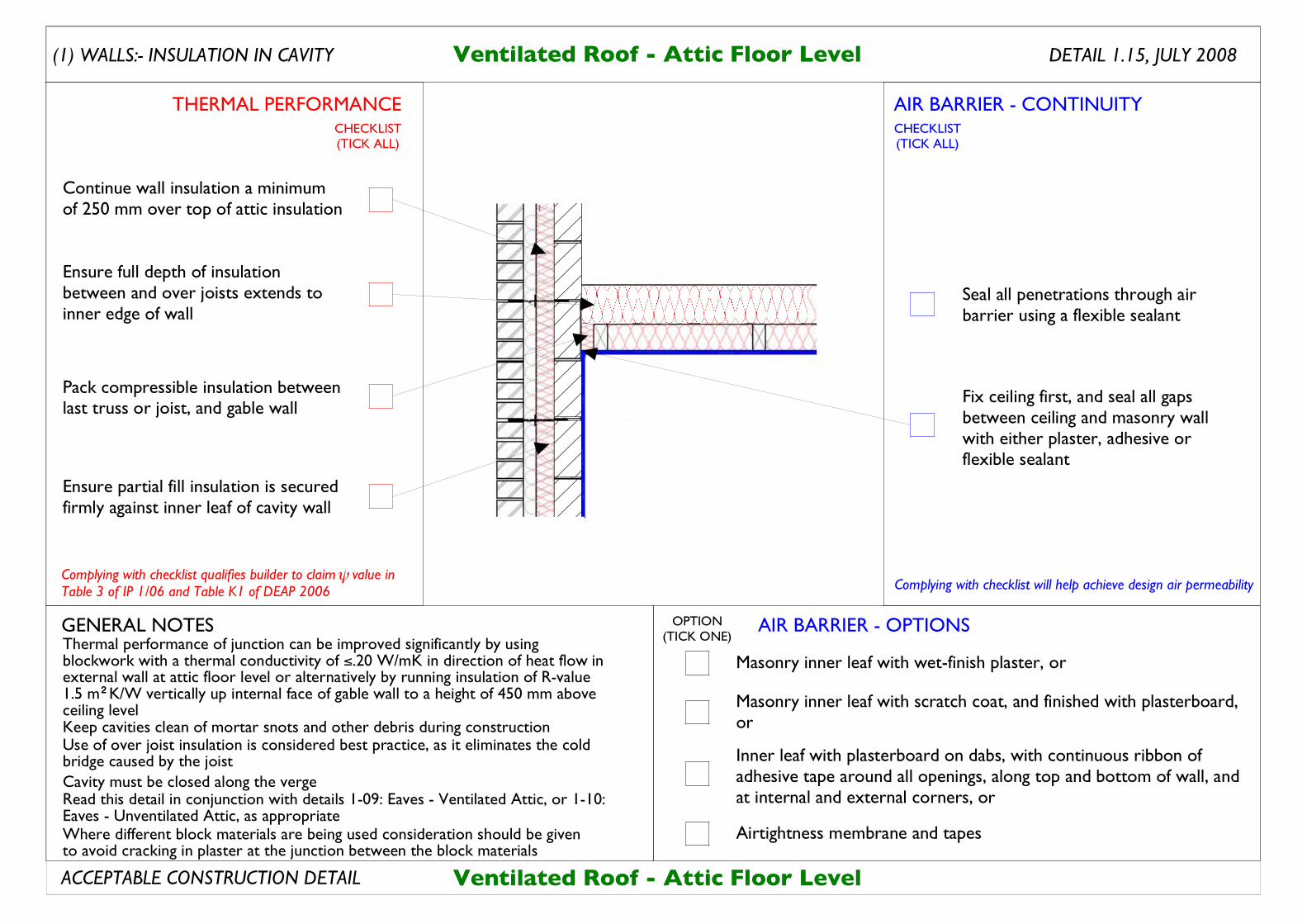
Keep cavities clean of mortar snots and other debris during construction
DETAIL 1.15, JULY 2008Ventilated Roof - Attic Floor Level
Use of over joist insulation is considered best practice, as it eliminates the cold bridge caused by the joist
Read this detail in conjunction with details 1-09: Eaves - Ventilated Attic, or 1-10: Eaves - Unventilated Attic, as appropriate
Ensure partial fill insulation is secured firmly against inner leaf of cavity wall
Ensure full depth of insulation between and over joists extends to inner edge of wall
Pack compressible insulation between last truss or joist, and gable wall
Seal all penetrations through air barrier using a flexible sealant
Fix ceiling first, and seal all gaps between ceiling and masonry wall with either plaster, adhesive or flexible sealant
Thermal performance of junction can be improved significantly by using blockwork with a thermal conductivity of ≤.20 W/mK in direction of heat flow in external wall at attic floor level or alternatively by running insulation of R-value 1.5 m K/W vertically up internal face of gable wall to a height of 450 mm above ceiling level
Cavity must be closed along the verge
Continue wall insulation a minimum of 250 mm over top of attic insulation
2
Where different block materials are being used consideration should be given to avoid cracking in plaster at the junction between the block materials
AIR BARRIER - CONTINUITY
AIR BARRIER - OPTIONS
THERMAL PERFORMANCE
(1) WALLS:- INSULATION IN CAVITY
Complying with checklist will help achieve design air permeability
GENERAL NOTES
ACCEPTABLE CONSTRUCTION DETAIL
CHECKLIST(TICK ALL)
CHECKLIST(TICK ALL)
OPTION(TICK ONE)
Masonry inner leaf with wet-finish plaster, or
Inner leaf with plasterboard on dabs, with continuous ribbon of adhesive tape around all openings, along top and bottom of wall, and at internal and external corners, or
Masonry inner leaf with scratch coat, and finished with plasterboard, or
Airtightness membrane and tapes
Complying with checklist qualifies builder to claim value in Table 3 of IP 1/06 and Table K1 of DEAP 2006
ψ
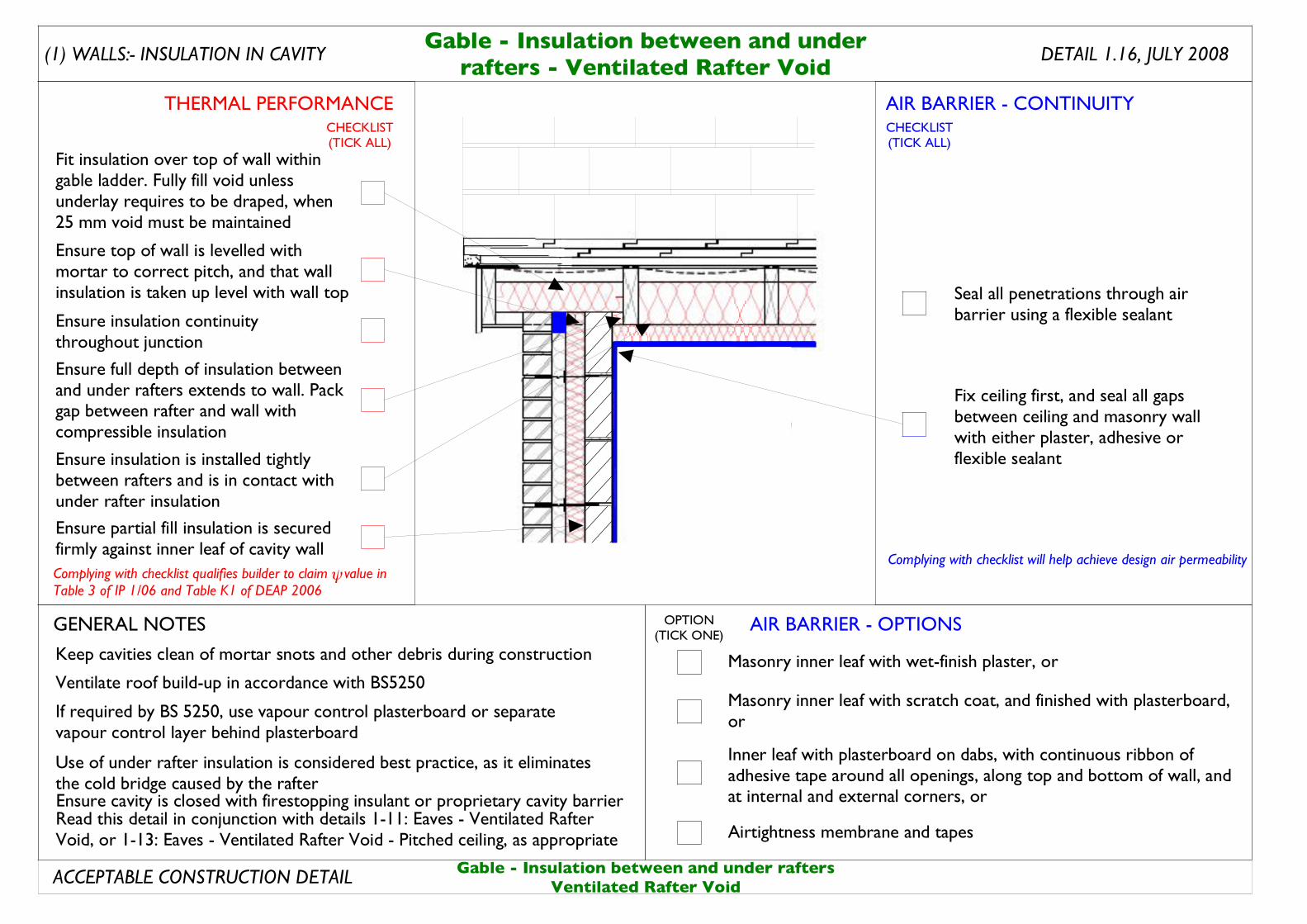
DETAIL 1.16, JULY 2008Gable - Insulation between and under
rafters - Ventilated Rafter Void
Seal all penetrations through air barrier using a flexible sealant
Fix ceiling first, and seal all gaps between ceiling and masonry wall with either plaster, adhesive or flexible sealant
Ensure partial fill insulation is secured firmly against inner leaf of cavity wall
Ensure insulation is installed tightly between rafters and is in contact with under rafter insulation
Ensure full depth of insulation between and under rafters extends to wall. Pack gap between rafter and wall with compressible insulation
Fit insulation over top of wall within gable ladder. Fully fill void unless underlay requires to be draped, when 25 mm void must be maintained
Ensure insulation continuity throughout junction
Ensure top of wall is levelled with mortar to correct pitch, and that wall insulation is taken up level with wall top
Keep cavities clean of mortar snots and other debris during construction
Use of under rafter insulation is considered best practice, as it eliminates the cold bridge caused by the rafter
Read this detail in conjunction with details 1-11: Eaves - Ventilated Rafter Void, or 1-13: Eaves - Ventilated Rafter Void - Pitched ceiling, as appropriate
Ventilate roof build-up in accordance with BS5250
If required by BS 5250, use vapour control plasterboard or separate vapour control layer behind plasterboard
Gable - Insulation between and under raftersVentilated Rafter Void
AIR BARRIER - CONTINUITY
AIR BARRIER - OPTIONS
THERMAL PERFORMANCE
(1) WALLS:- INSULATION IN CAVITY
Complying with checklist will help achieve design air permeability
GENERAL NOTES
ACCEPTABLE CONSTRUCTION DETAIL
CHECKLIST(TICK ALL)
CHECKLIST(TICK ALL)
OPTION(TICK ONE)
Masonry inner leaf with wet-finish plaster, or
Inner leaf with plasterboard on dabs, with continuous ribbon of adhesive tape around all openings, along top and bottom of wall, and at internal and external corners, or
Masonry inner leaf with scratch coat, and finished with plasterboard, or
Airtightness membrane and tapes
Ensure cavity is closed with firestopping insulant or proprietary cavity barrier
Complying with checklist qualifies builder to claim value in Table 3 of IP 1/06 and Table K1 of DEAP 2006
ψ
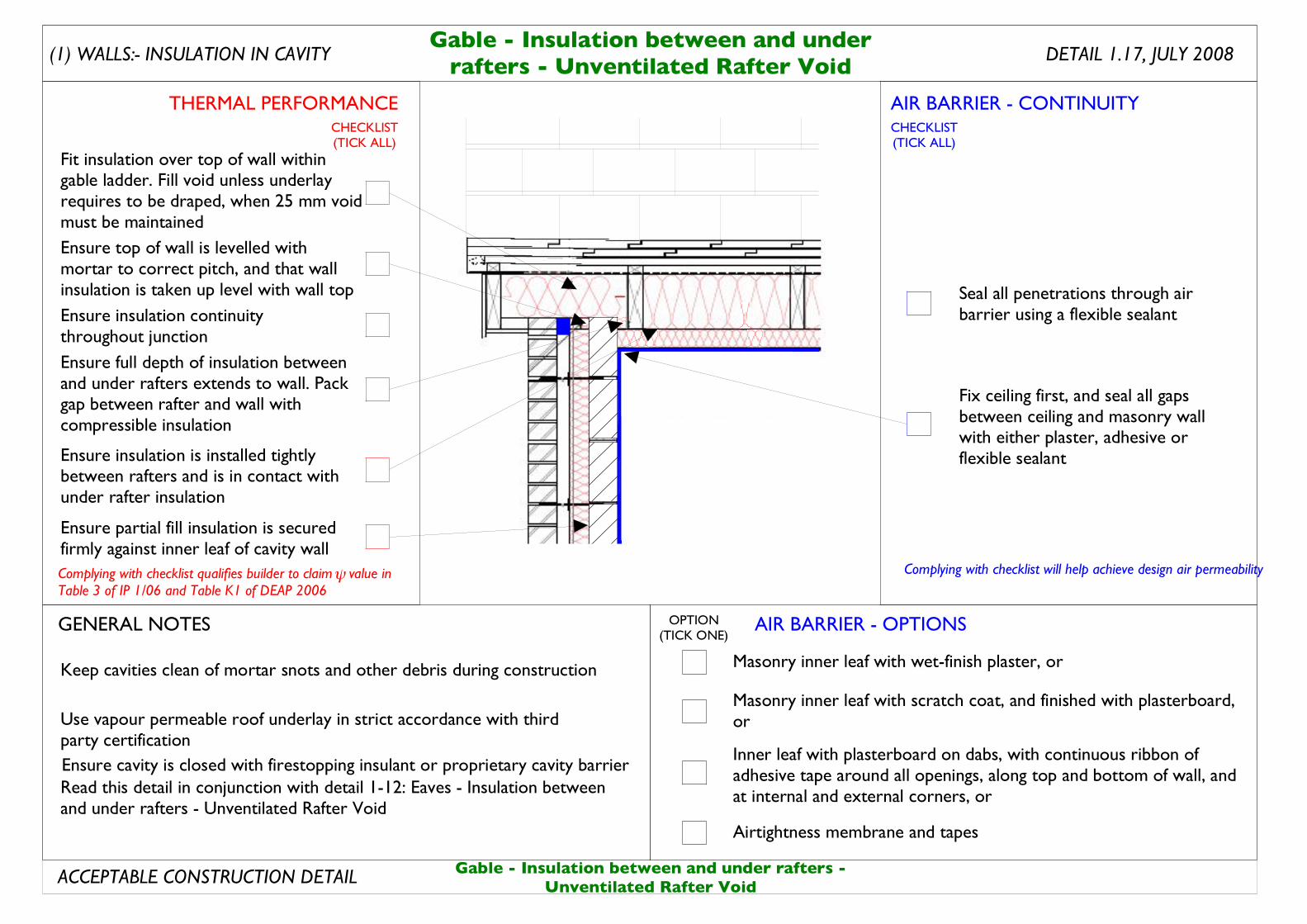
Keep cavities clean of mortar snots and other debris during construction
Read this detail in conjunction with detail 1-12: Eaves - Insulation between and under rafters - Unventilated Rafter Void
Use vapour permeable roof underlay in strict accordance with third party certification
DETAIL 1.17, JULY 2008
Ensure insulation continuity throughout junction
Ensure top of wall is levelled with mortar to correct pitch, and that wall insulation is taken up level with wall top
Fit insulation over top of wall within gable ladder. Fill void unless underlay requires to be draped, when 25 mm void must be maintained
Ensure partial fill insulation is secured firmly against inner leaf of cavity wall
Ensure insulation is installed tightly between rafters and is in contact with under rafter insulation
Ensure full depth of insulation between and under rafters extends to wall. Pack gap between rafter and wall with compressible insulation
Seal all penetrations through air barrier using a flexible sealant
Fix ceiling first, and seal all gaps between ceiling and masonry wall with either plaster, adhesive or flexible sealant
Gable - Insulation between and underrafters - Unventilated Rafter Void
Gable - Insulation between and under rafters -Unventilated Rafter Void
AIR BARRIER - CONTINUITY
AIR BARRIER - OPTIONS
THERMAL PERFORMANCE
(1) WALLS:- INSULATION IN CAVITY
Complying with checklist will help achieve design air permeability
GENERAL NOTES
ACCEPTABLE CONSTRUCTION DETAIL
CHECKLIST(TICK ALL)
CHECKLIST(TICK ALL)
OPTION(TICK ONE)
Masonry inner leaf with wet-finish plaster, or
Inner leaf with plasterboard on dabs, with continuous ribbon of adhesive tape around all openings, along top and bottom of wall, and at internal and external corners, or
Masonry inner leaf with scratch coat, and finished with plasterboard, or
Airtightness membrane and tapes
Ensure cavity is closed with firestopping insulant or proprietary cavity barrier
Complying with checklist qualifies builder to claim value in Table 3 of IP 1/06 and Table K1 of DEAP 2006
ψ
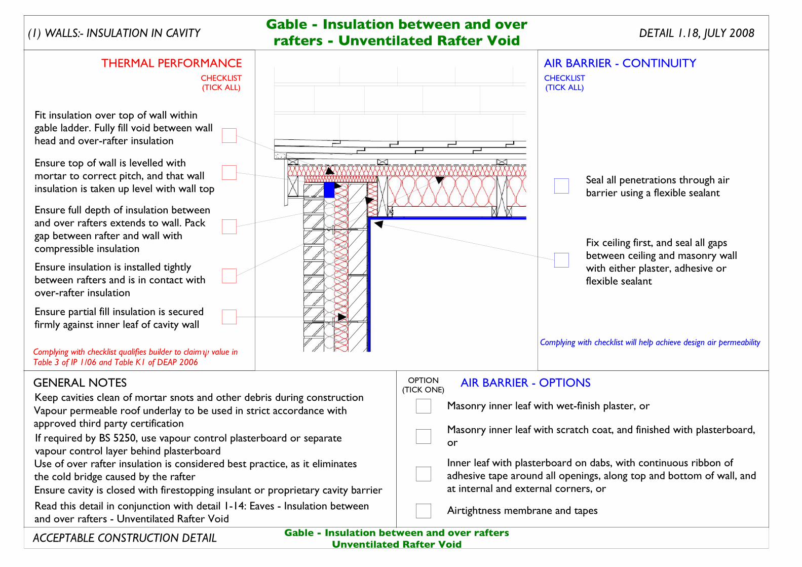
Gable - Insulation between and overrafters - Unventilated Rafter Void
DETAIL 1.18, JULY 2008
Keep cavities clean of mortar snots and other debris during construction
Use of over rafter insulation is considered best practice, as it eliminates the cold bridge caused by the rafter
Read this detail in conjunction with detail 1-14: Eaves - Insulation between and over rafters - Unventilated Rafter Void
Vapour permeable roof underlay to be used in strict accordance with approved third party certificationIf required by BS 5250, use vapour control plasterboard or separate vapour control layer behind plasterboard
Seal all penetrations through air barrier using a flexible sealant
Fix ceiling first, and seal all gaps between ceiling and masonry wall with either plaster, adhesive or flexible sealant
Ensure top of wall is levelled with mortar to correct pitch, and that wall insulation is taken up level with wall top
Fit insulation over top of wall within gable ladder. Fully fill void between wall head and over-rafter insulation
Ensure partial fill insulation is secured firmly against inner leaf of cavity wall
Ensure insulation is installed tightly between rafters and is in contact with over-rafter insulation
Ensure full depth of insulation between and over rafters extends to wall. Pack gap between rafter and wall with compressible insulation
Gable - Insulation between and over raftersUnventilated Rafter Void
AIR BARRIER - CONTINUITY
AIR BARRIER - OPTIONS
THERMAL PERFORMANCE
(1) WALLS:- INSULATION IN CAVITY
Complying with checklist will help achieve design air permeability
GENERAL NOTES
ACCEPTABLE CONSTRUCTION DETAIL
CHECKLIST(TICK ALL)
CHECKLIST(TICK ALL)
OPTION(TICK ONE)
Masonry inner leaf with wet-finish plaster, or
Inner leaf with plasterboard on dabs, with continuous ribbon of adhesive tape around all openings, along top and bottom of wall, and at internal and external corners, or
Masonry inner leaf with scratch coat, and finished with plasterboard, or
Airtightness membrane and tapes
Ensure cavity is closed with firestopping insulant or proprietary cavity barrier
Complying with checklist qualifies builder to claim value in Table 3 of IP 1/06 and Table K1 of DEAP 2006
ψ
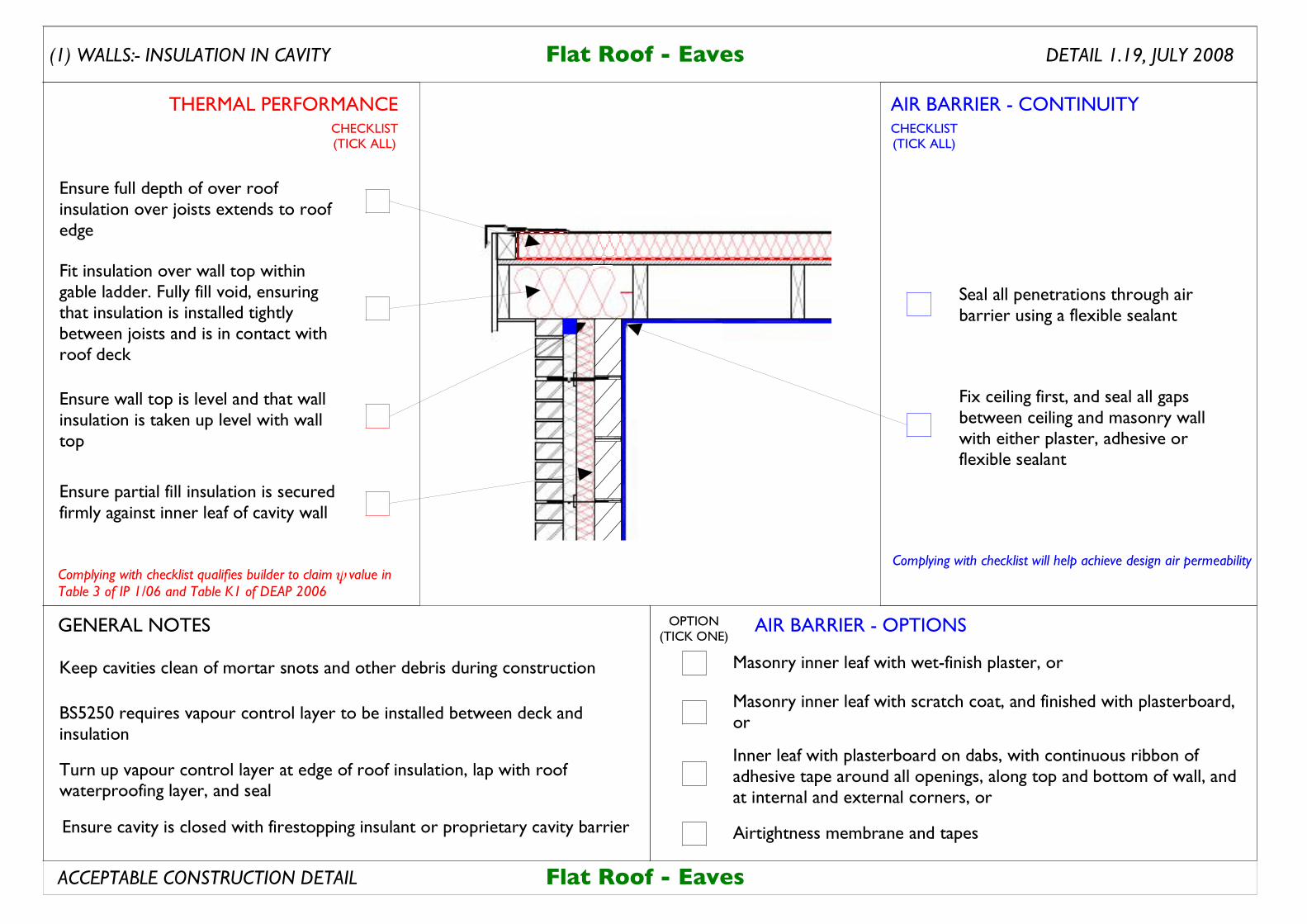
Flat Roof - Eaves
Keep cavities clean of mortar snots and other debris during construction
Seal all penetrations through air barrier using a flexible sealant
Fix ceiling first, and seal all gaps between ceiling and masonry wall with either plaster, adhesive or flexible sealant
Ensure partial fill insulation is secured firmly against inner leaf of cavity wall
Ensure full depth of over roof insulation over joists extends to roof edge
Fit insulation over wall top within gable ladder. Fully fill void, ensuring that insulation is installed tightly between joists and is in contact with roof deck
Ensure wall top is level and that wall insulation is taken up level with wall top
Turn up vapour control layer at edge of roof insulation, lap with roof waterproofing layer, and seal
BS5250 requires vapour control layer to be installed between deck and insulation
Flat Roof - Eaves
DETAIL 1.19, JULY 2008
AIR BARRIER - CONTINUITY
AIR BARRIER - OPTIONS
THERMAL PERFORMANCE
(1) WALLS:- INSULATION IN CAVITY
Complying with checklist will help achieve design air permeability
GENERAL NOTES
ACCEPTABLE CONSTRUCTION DETAIL
CHECKLIST(TICK ALL)
CHECKLIST(TICK ALL)
OPTION(TICK ONE)
Masonry inner leaf with wet-finish plaster, or
Inner leaf with plasterboard on dabs, with continuous ribbon of adhesive tape around all openings, along top and bottom of wall, and at internal and external corners, or
Masonry inner leaf with scratch coat, and finished with plasterboard, or
Airtightness membrane and tapesEnsure cavity is closed with firestopping insulant or proprietary cavity barrier
Complying with checklist qualifies builder to claim value in Table 3 of IP 1/06 and Table K1 of DEAP 2006
!
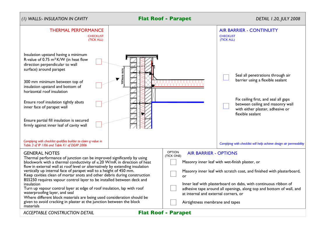
Thermal performance of junction can be improved significantly by using blockwork with a thermal conductivity of ".20 W/mK in direction of heat flow in external wall at roof level or alternatively by extending insulation vertically up internal face of parapet wall to a height of 450 mm.
Flat Roof - Parapet
Keep cavities clean of mortar snots and other debris during construction
Turn up vapour control layer at edge of roof insulation, lap with roof waterproofing layer, and seal
BS5250 requires vapour control layer to be installed between deck and insulation
Seal all penetrations through air barrier using a flexible sealant
Fix ceiling first, and seal all gaps between ceiling and masonry wall with either plaster, adhesive or flexible sealant
Ensure partial fill insulation is secured firmly against inner leaf of cavity wall
Ensure roof insulation tightly abuts inner face of parapet wall
300 mm minimum between top of insulation upstand and bottom of horizontal roof insulation
Insulation upstand having a minimum R-value of 0.75 m K/W (in heat flow direction perpendicular to wall surface) around parapet
2
Flat Roof - Parapet
DETAIL 1.20, JULY 2008
Where different block materials are being used consideration should be given to avoid cracking in plaster at the junction between the block materials
AIR BARRIER - CONTINUITY
AIR BARRIER - OPTIONS
THERMAL PERFORMANCE
(1) WALLS:- INSULATION IN CAVITY
Complying with checklist will help achieve design air permeability
GENERAL NOTES
ACCEPTABLE CONSTRUCTION DETAIL
CHECKLIST(TICK ALL)
CHECKLIST(TICK ALL)
OPTION(TICK ONE)
Masonry inner leaf with wet-finish plaster, or
Inner leaf with plasterboard on dabs, with continuous ribbon of adhesive tape around all openings, along top and bottom of wall, and at internal and external corners, or
Masonry inner leaf with scratch coat, and finished with plasterboard, or
Airtightness membrane and tapes
Complying with checklist qualifies builder to claim value in Table 3 of IP 1/06 and Table K1 of DEAP 2006
!
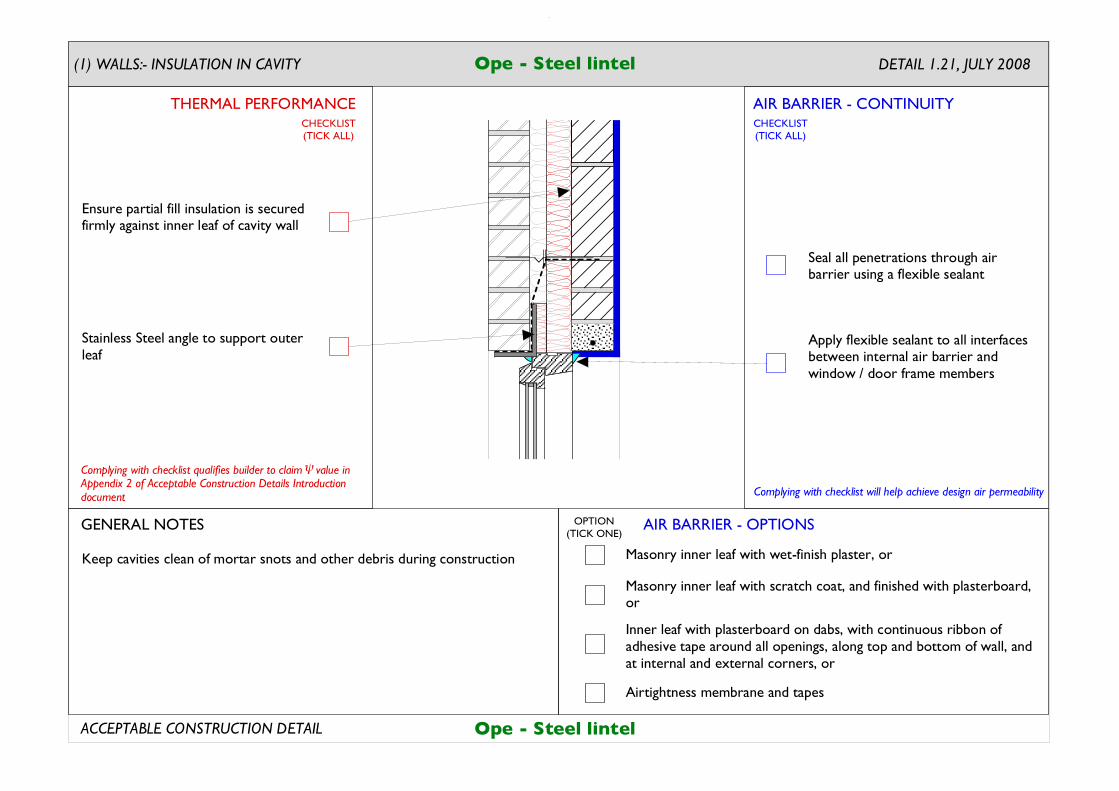
DETAIL 1.21, JULY 2008
Keep cavities clean of mortar snots and other debris during construction
Seal all penetrations through air barrier using a flexible sealant
Apply flexible sealant to all interfaces between internal air barrier and window / door frame members
Ensure partial fill insulation is secured firmly against inner leaf of cavity wall
Stainless Steel angle to support outer leaf
Ope - Steel lintel
Ope - Steel lintel
Complying with checklist qualifies builder to claim value in Appendix 2 of Acceptable Construction Details Introduction document
!
AIR BARRIER - CONTINUITY
AIR BARRIER - OPTIONS
THERMAL PERFORMANCE
(1) WALLS:- INSULATION IN CAVITY
Complying with checklist will help achieve design air permeability
GENERAL NOTES
ACCEPTABLE CONSTRUCTION DETAIL
CHECKLIST(TICK ALL)
CHECKLIST(TICK ALL)
OPTION(TICK ONE)
Masonry inner leaf with wet-finish plaster, or
Inner leaf with plasterboard on dabs, with continuous ribbon of adhesive tape around all openings, along top and bottom of wall, and at internal and external corners, or
Masonry inner leaf with scratch coat, and finished with plasterboard, or
Airtightness membrane and tapes
Complying with checklist qualifies builder to claim value in Table 3 of IP 1/06 and Table K1 of DEAP 2006
!
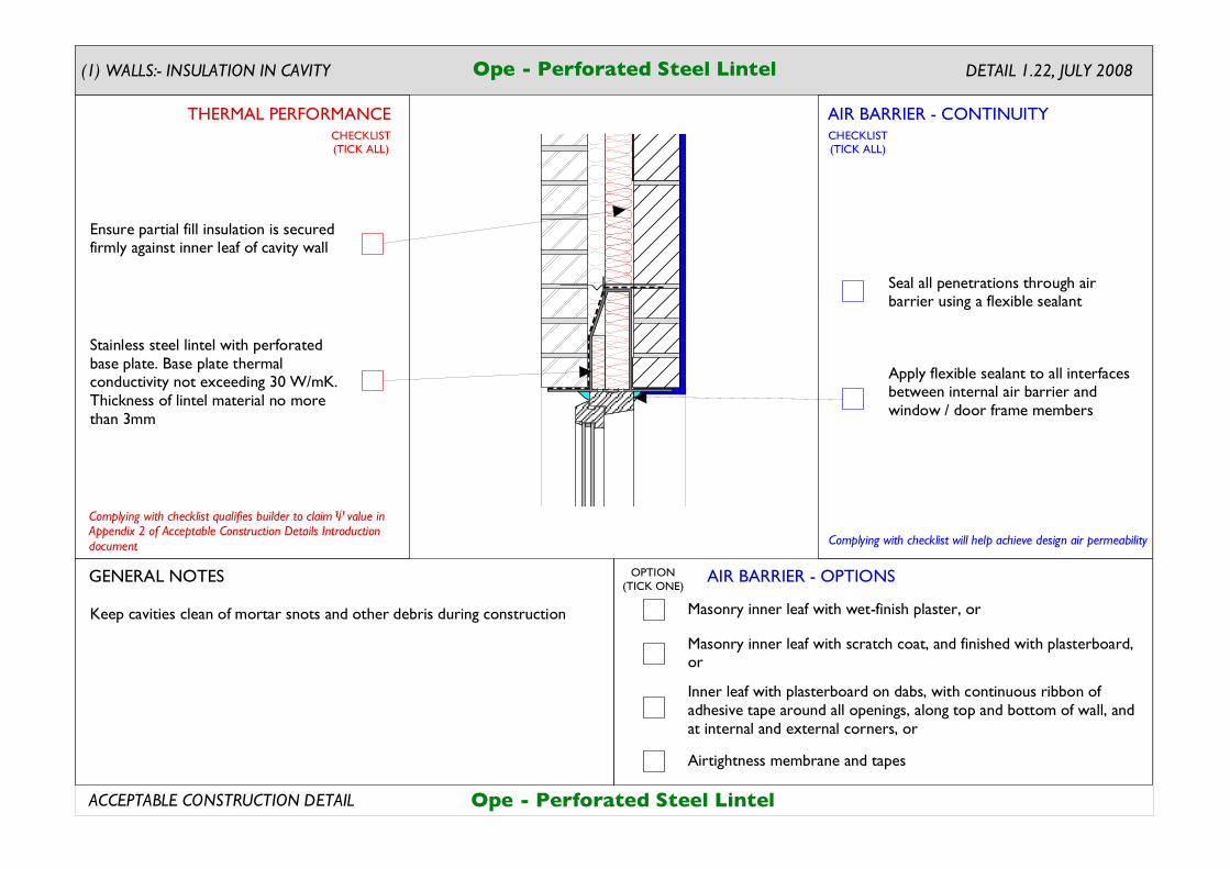
Ope - Perforated Steel Lintel
DETAIL 1.22, JULY 2008Ope - Perforated Steel Lintel
Keep cavities clean of mortar snots and other debris during construction
Seal all penetrations through air barrier using a flexible sealant
Apply flexible sealant to all interfaces between internal air barrier and window / door frame members
Ensure partial fill insulation is secured firmly against inner leaf of cavity wall
Stainless steel lintel with perforated base plate. Base plate thermal conductivity not exceeding 30 W/mK.Thickness of lintel material no more than 3mm
Complying with checklist qualifies builder to claim value in Appendix 2 of Acceptable Construction Details Introduction document
!
AIR BARRIER - CONTINUITY
AIR BARRIER - OPTIONS
THERMAL PERFORMANCE
(1) WALLS:- INSULATION IN CAVITY
Complying with checklist will help achieve design air permeability
GENERAL NOTES
ACCEPTABLE CONSTRUCTION DETAIL
CHECKLIST(TICK ALL)
CHECKLIST(TICK ALL)
OPTION(TICK ONE)
Masonry inner leaf with wet-finish plaster, or
Inner leaf with plasterboard on dabs, with continuous ribbon of adhesive tape around all openings, along top and bottom of wall, and at internal and external corners, or
Masonry inner leaf with scratch coat, and finished with plasterboard, or
Airtightness membrane and tapes
Complying with checklist qualifies builder to claim value in Table 3 of IP 1/06 and Table K1 of DEAP 2006
!
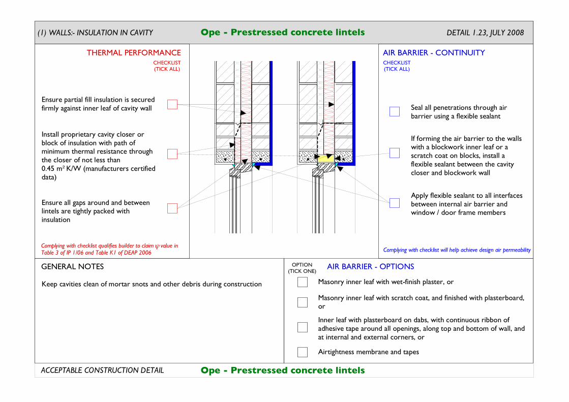
Ope - Prestressed concrete lintels
Seal all penetrations through air barrier using a flexible sealant
Apply flexible sealant to all interfaces between internal air barrier and window / door frame members
Keep cavities clean of mortar snots and other debris during construction
If forming the air barrier to the walls with a blockwork inner leaf or a scratch coat on blocks, install a flexible sealant between the cavity closer and blockwork wall
Ensure all gaps around and between lintels are tightly packed with insulation
Ensure partial fill insulation is secured firmly against inner leaf of cavity wall
DETAIL 1.23, JULY 2008
Ope - Prestressed concrete lintels
Install proprietary cavity closer or block of insulation with path of minimum thermal resistance through the closer of not less than 0.45 m K/W (manufacturers certified data)
2
AIR BARRIER - CONTINUITY
AIR BARRIER - OPTIONS
THERMAL PERFORMANCE
(1) WALLS:- INSULATION IN CAVITY
Complying with checklist will help achieve design air permeability
GENERAL NOTES
ACCEPTABLE CONSTRUCTION DETAIL
CHECKLIST(TICK ALL)
CHECKLIST(TICK ALL)
OPTION(TICK ONE)
Masonry inner leaf with wet-finish plaster, or
Inner leaf with plasterboard on dabs, with continuous ribbon of adhesive tape around all openings, along top and bottom of wall, and at internal and external corners, or
Masonry inner leaf with scratch coat, and finished with plasterboard, or
Airtightness membrane and tapes
Complying with checklist qualifies builder to claim value in Table 3 of IP 1/06 and Table K1 of DEAP 2006
!
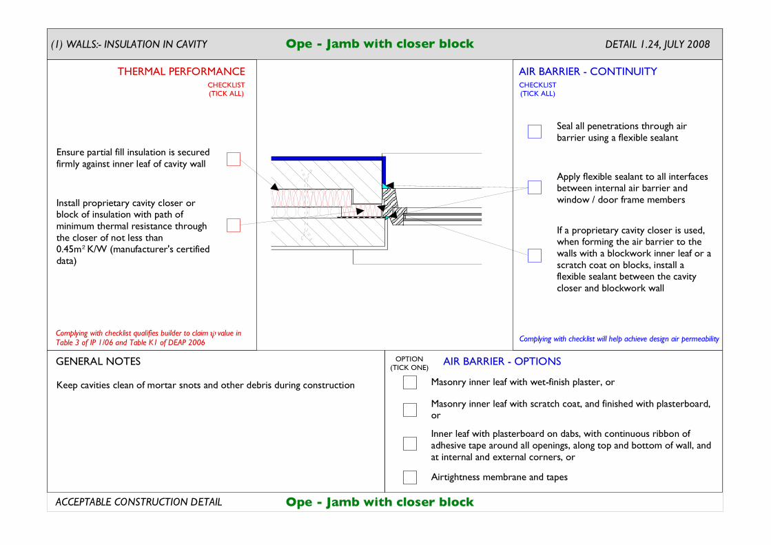
Ope - Jamb with closer block DETAIL 1.24, JULY 2008
Keep cavities clean of mortar snots and other debris during construction
Seal all penetrations through air barrier using a flexible sealant
Apply flexible sealant to all interfaces between internal air barrier and window / door frame members
Ensure partial fill insulation is secured firmly against inner leaf of cavity wall
If a proprietary cavity closer is used, when forming the air barrier to the walls with a blockwork inner leaf or a scratch coat on blocks, install a flexible sealant between the cavity closer and blockwork wall
Install proprietary cavity closer or block of insulation with path of minimum thermal resistance through the closer of not less than 0.45m K/W (manufacturer's certified data)
2
Ope - Jamb with closer block
AIR BARRIER - CONTINUITY
AIR BARRIER - OPTIONS
THERMAL PERFORMANCE
(1) WALLS:- INSULATION IN CAVITY
Complying with checklist will help achieve design air permeability
GENERAL NOTES
ACCEPTABLE CONSTRUCTION DETAIL
CHECKLIST(TICK ALL)
CHECKLIST(TICK ALL)
OPTION(TICK ONE)
Masonry inner leaf with wet-finish plaster, or
Inner leaf with plasterboard on dabs, with continuous ribbon of adhesive tape around all openings, along top and bottom of wall, and at internal and external corners, or
Masonry inner leaf with scratch coat, and finished with plasterboard, or
Airtightness membrane and tapes
Complying with checklist qualifies builder to claim value in Table 3 of IP 1/06 and Table K1 of DEAP 2006
!
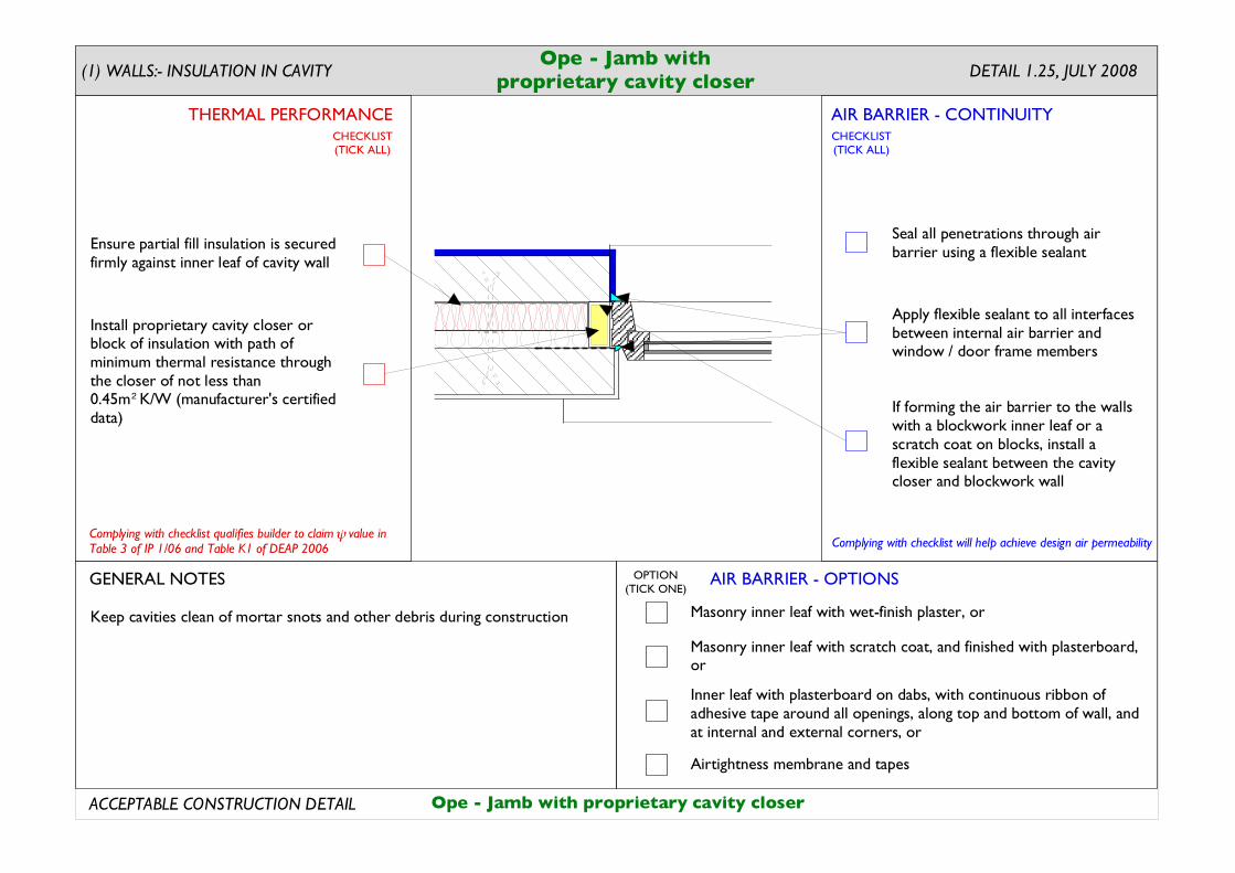
Ope - Jamb withproprietary cavity closer
Keep cavities clean of mortar snots and other debris during construction
Seal all penetrations through air barrier using a flexible sealant
Apply flexible sealant to all interfaces between internal air barrier and window / door frame members
If forming the air barrier to the walls with a blockwork inner leaf or a scratch coat on blocks, install a flexible sealant between the cavity closer and blockwork wall
Ensure partial fill insulation is secured firmly against inner leaf of cavity wall
DETAIL 1.25, JULY 2008
Ope - Jamb with proprietary cavity closer
Install proprietary cavity closer or block of insulation with path of minimum thermal resistance through the closer of not less than 0.45m K/W (manufacturer's certified data)
2
AIR BARRIER - CONTINUITY
AIR BARRIER - OPTIONS
THERMAL PERFORMANCE
(1) WALLS:- INSULATION IN CAVITY
Complying with checklist will help achieve design air permeability
GENERAL NOTES
ACCEPTABLE CONSTRUCTION DETAIL
CHECKLIST(TICK ALL)
CHECKLIST(TICK ALL)
OPTION(TICK ONE)
Masonry inner leaf with wet-finish plaster, or
Inner leaf with plasterboard on dabs, with continuous ribbon of adhesive tape around all openings, along top and bottom of wall, and at internal and external corners, or
Masonry inner leaf with scratch coat, and finished with plasterboard, or
Airtightness membrane and tapes
Complying with checklist qualifies builder to claim value in Table 3 of IP 1/06 and Table K1 of DEAP 2006
!
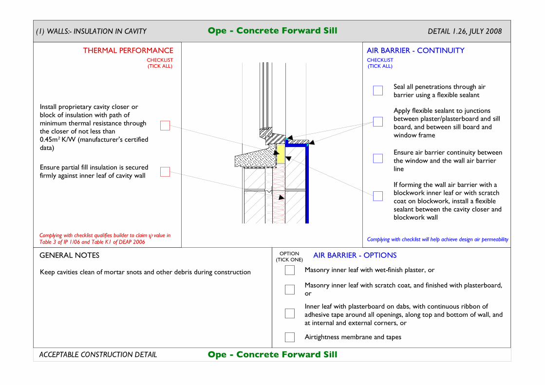
Ope - Concrete Forward Sill DETAIL 1.26, JULY 2008
Keep cavities clean of mortar snots and other debris during construction
Ensure partial fill insulation is secured firmly against inner leaf of cavity wall
Seal all penetrations through air barrier using a flexible sealant
Apply flexible sealant to junctions between plaster/plasterboard and sill board, and between sill board and window frame
Ensure air barrier continuity between the window and the wall air barrier line
If forming the wall air barrier with a blockwork inner leaf or with scratch coat on blockwork, install a flexible sealant between the cavity closer and blockwork wall
Ope - Concrete Forward Sill
Install proprietary cavity closer or block of insulation with path of minimum thermal resistance through the closer of not less than 0.45m K/W (manufacturer's certified data)
2
AIR BARRIER - CONTINUITY
AIR BARRIER - OPTIONS
THERMAL PERFORMANCE
(1) WALLS:- INSULATION IN CAVITY
Complying with checklist will help achieve design air permeability
GENERAL NOTES
ACCEPTABLE CONSTRUCTION DETAIL
CHECKLIST(TICK ALL)
CHECKLIST(TICK ALL)
OPTION(TICK ONE)
Masonry inner leaf with wet-finish plaster, or
Inner leaf with plasterboard on dabs, with continuous ribbon of adhesive tape around all openings, along top and bottom of wall, and at internal and external corners, or
Masonry inner leaf with scratch coat, and finished with plasterboard, or
Airtightness membrane and tapes