university of huddersfield repositoryeprints.hud.ac.uk/29510/1/a validated finite element method...
TRANSCRIPT

University of Huddersfield Repository
Li, Guoxing, Gu, Fengshou, Wei, Nasha, Xu, Yuandong and Ball, Andrew
A validated finite element model for predicting dynamic responses of cylinder liners in an IC engine*
Original Citation
Li, Guoxing, Gu, Fengshou, Wei, Nasha, Xu, Yuandong and Ball, Andrew (2016) A validated finite element model for predicting dynamic responses of cylinder liners in an IC engine*. In: Proceedings 22nd International Conference on Automation and Computing (ICAC). IEEE. ISBN 9781862181328
This version is available at http://eprints.hud.ac.uk/id/eprint/29510/
The University Repository is a digital collection of the research output of theUniversity, available on Open Access. Copyright and Moral Rights for the itemson this site are retained by the individual author and/or other copyright owners.Users may access full items free of charge; copies of full text items generallycan be reproduced, displayed or performed and given to third parties in anyformat or medium for personal research or study, educational or notforprofitpurposes without prior permission or charge, provided:
• The authors, title and full bibliographic details is credited in any copy;• A hyperlink and/or URL is included for the original metadata page; and• The content is not changed in any way.
For more information, including our policy and submission procedure, pleasecontact the Repository Team at: [email protected].
http://eprints.hud.ac.uk/

A validated finite element model for predicting dynamic responses of cylinder liners in an IC engine*
Guoxing Li, Fengshou Gu, Nasha Wei, Yuandong Xu, Andrew D. Ball
Centre for Efficiency and Performance Engineering University of Huddersfield
HD1 3DH, Huddersfield, UK [email protected], [email protected]
Tie Wang, Fengshou Gu, Guoxing Li Department of Vehicle Engineering Taiyuan University of Technology
Taiyuan, P.R.China [email protected]
Abstract—Vibration of cylinder liners affects not only engine
combustion performances but also tribological behaviour and noise radiations. However, it is difficult to characterize it experimentally due to multiple sources, strong background noise, and nonlinear transfer paths. Therefore, a finite element model is established in this study to predict the dynamic responses of cylinder liners under respective sources. The model takes into account both the characteristics of structural modes and nonlinearities of assembly constraints when selecting adequate elements for efficient computation of the responses under both the highly nonlinear combustion pressure excitations and subsequent piston slap impacts. The predictions are then evaluated against experimental results under different engine operating conditions. In addition, continuous wavelet analysis is employed to process the complicated responses for key response events and their frequency ranges. The results show agreeable correspondences between the numerical predictions and measured vibration signals, paving the way for investigating its effect on combustion and lubrication processes.
Keywords—finite element; dynamic response; piston slap; combustion pressure; cylinder liner
I. INTRODUCTION The piston assembly is one of engine’s subsystems that
determine the performances of friction, lubrication, noise, vibration and hence service lifespan. Previous studies showed that over 80% of the total engine vibration and noise emissions can be attributed to the dynamic response of cylinder liners under the excitation of the in-cylinder combustion and its consequent piston slaps [1]. Moreover, this high fraction of vibration implies that dynamic interactions are rather intensive amongst mixture combustions, hydrodynamic lubrication, and liner dynamics. Therefore, active researches have been carried out in order to improve the dynamic behaviours of cylinder liners.
Structural analysis of cylinder liners has been reported using finite element analysis (FEA) [2]–[4]. The static deformation, forced response analysis and frequency response analysis of cylinder liners were undertaken based on finite element models, for impact force calculation and liner response analysis [4]. However, the majority of these FEM-based studies were performed based on a quasi-static model which the modal characteristics and reaction upon piston of cylinder liners were neglected. Obviously, such models may not be able to reflect the phenomena of true contacts between piston and cylinder due to invertible elastic deformations under dynamic forces.
Compared to shell elements, solid elements can better describe the geometric details of liner flanges, to facilitate the modelling of more realistic boundary conditions, although it comes at the cost of longer solution time [5]. To enhance the computing efficiency, Jafari et al. [3] derived the dynamic response of cylindrical shells using mode superposition method, which is recognized as the most powerful method to solve the equation sets of linear system considering the required solution time. While the contact constraint widely existed in cylinder assembly is a typical nonlinear kinematic pair, which cannot be handled by the mode superposition method [6]. To compensate, based on a direct Newmark integration method, Hirotaka Murakami et al. [7] implemented the structure analysis of piston-cylinder assembly, coupling with multi-body dynamics analysis. However, due to excessive requirement for computational sources, numerical prediction of cylinder dynamic responses contain modal frequencies has not yet been achieved.
To gain an in-depth understanding of the dynamic responses of cylinder liners to in-cylinder combustion force and piston slaps, a finite element model is developed by taking into account both structural modal characteristics, nonlinearities of assembly constraints and time-varying exciting forces. The paper is organized into four sections in addressing the subject. Section II details the development of FEM-based model which includes model validation against experimental measurements from a single-cylinder diesel engine. Section III investigates the correlation between the numerical and experimental results and evaluates the liner’s responses upon measured forces. Section IV summarizes the conclusions obtained through this initial work.
II. STRUCTURAL CHARACTERISTICS AND DYNAMIC BEHAVIOURS OF CYLINDER LINERS
A. Establishment of finite element model Cylinder liners, also known as cylinder sleeves, are the
central components of a reciprocating engine. Fig.1 shows a typical construction of the cylinder liner. The upper flange of cylinder liner is connected to the cylinder head and body through bolts, thus limiting its axial degree of freedom. Both the upper and bottom external surfaces of liner are mounted onto the block within clearance fitting. To prevent leakage of liquid coolant into the crankcase, the lower end of the wet liner is sealed with the help of rubber sealing ring rather than being forced constraint with the engine block. It undertakes not only harsh combustion shocks but also strong piston slaps, which
The project of this paper is supported by Natural and Scientific foundation of China.(NO. 51375326).
can affect tribological behaviour and oil consumption while it contributes significantly to engine vibration and noise emissions.
Cylinder head
Upper flange
Cylinder block
Liner
Liquid coolant
Sealing ring
Y
Z
Figure 1 Construction of wet cylinder liner
1) Meshing and solution algorithm Compared with shell elements, solid elements can better
describe the geometric details of liner flanges in achieving a more realistic boundary condition, although it comes at the cost of longer solution time. For the balance between better accuracy and efficiency, hexahedral elements are adopted for three-dimensional meshes. To obtain the localised instantaneous deformations on the flanges at top end and the overall cylindrical shell, the model was configured to have 7121 hexahedral isoparametric solid elements using ANSYS Workbench. This finer element mesh arrangement is also taken into account that the vibration can have frequency contents as high as 10 kHz which was estimated based analytic analysis when the liner is assumed to be an uniform cylindrical shell [8]. To reduce the need for solution time and computing sources, the external surface of the liner and all the other components were treat as rigid body in modelling.
For dynamic simulations, modal superposition method is the most powerful method to solve the set of equations considering the required solution time. But, this method cannot handle the nonlinearities when the contact constraint is applied to the cylinder assembly. Thus, the Newmark implicit integration method was used to solve nonlinear model in cylinder dynamic simulation. To improve the computing efficiency, the Reduced Method, one subclass of Newmark implicit integration method, was chosen to solve the motion equations of dynamic process. Because of the reduced system matrices which are used to solve the transient problem, it has an advantage when compared with the Full Method with respect to the required solution time.
2) Material and Boundary Conditions Wet liners, or sleeves, are widely used in heavy-duty diesel
engines, which permit engines to undertake high combustion loads without overheating because the coolant is in direct contact with the sleeve. A wet liner is essentially a stand-alone cylinder, supported at the top and bottom by the block, and surrounded by the water jacket.
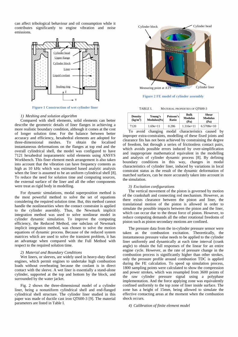
Fig. 2 shows the three-dimensional model of a cylinder liner, being a nonuniform cylindrical shell and end-flanged cylindrical shell structure. The cylinder liner studied in this paper was made of ductile cast iron QT600-3 [9]. The material parameters are listed in Table I.
Cylinder block Cylinder head
Measuring point at ATS Cylinder liner
Figure 2 FE model of cylinder assembly
TABLE I. MATERIAL PROPERTIES OF QT600-3
Density (kg/m3)
Young’s Modulus(Pa)
Poisson’s Ratio
Bulk Modulus
(Pa)
Shear Modulus
(Pa) 7120 1.69e+11 0.286 1.316e+11 6.5708e+10
To avoid changing modal characteristics caused by improper extra-constraints, modelling of these fixed joints and clearance fits has not been achieved by constraining the degree of freedom, but through a series of frictionless contact pairs, which avoids possible errors induced by over-simplification and inappropriate mathematical equivalent in the modelling and analysis of cylinder dynamic process [8]. By defining boundary conditions in this way, changes in modal characteristics of cylinder liner, induced by variations in local constraint status as the result of the dynamic deformation of matched surfaces, can be more accurately taken into account in the simulation.
3) Excitation configurations The vertical movement of the piston is governed by motion
of the crankshaft and connecting rod mechanism. However, as there exists clearance between the piston and liner, the translational motion of the piston is allowed in order to simulate the possible impacts between the piston and the liner, which can occur due to the thrust force of piston. However, to reduce computing demands all the other rotational freedoms of piston such as piston secondary motions are confined.
The pressure data from the in-cylinder pressure sensor were taken as the combustion excitation. Theoretically, the instantaneous pressure value needs to be applied to the cylinder liner uniformly and dynamically at each time interval (crank angle) to obtain the full responses of the linear for an entire engine cycle. However, as the rate of pressure change in the combustion process is significantly higher than other strokes, only the pressure profile around combustion TDC is applied during the FE calculation. To speed up simulation process, 1800 sampling points were calculated to show the compression and power strokes, which was resampled from 3600 points of the raw cylinder pressure signal using a polyphase implementation. And the force applying zone was equivalently confined uniformly to the top zone of liner inside surface. The zone has a height of 15mm, being allowed to simulate the effective contacting areas at the moment when the combustion shock occurs.
4) Calibration of finite element model

To verify and calibrate simulation parameters of the FE model, a modal test was conducted to obtain the free-free modal responses of the liner. Then modal frequencies from both the modal test and finite element predictions are compared to confirm the accuracy of the FE modelling.
As shown in the Table. II, the simulated modal frequencies are agreeable with the measured ones. Except for the first mode, which can have more error during the test, the difference of modal frequency is within 3% This shows that the configuration of material parameters and simplified geometric shape are appropriate for the modelling, and sufficient to represent and characterize the dynamic features of cylinder liner in the frequency range below 10kHz.
TABLE II. THE MODE FREQUENCY
No. Simulated Freq.(Hz)
Measured Freq.(Hz)
Error (%) No. Simulated
Freq.(Hz) Measured Freq.(Hz)
Error (%)
1 929.0 974.7 4.62 9 6673.2 6569.7 1.58 2 1229.7 1217.5 1.04 11 7926.9 7872.2 0.69 3 2567.3 2584.8 0.68 13 9011.1 8956.7 0.61 4 3128.7 3195.2 2.08 15 9879.4 9760.0 1.22 5 4191.4 4117.7 1.78 10 6979.5 6896.1 1.21 6 4301.5 4324.5 0.53 12 8732.6 8559.4 2.02 7 4847.0 4711.5 2.88 14 9321.0 9177.1 1.57 8 5832.1 5785.3 0.81 16 9939.9 10012.5 0.72
B. Vibration excitations of cylinder liners According to engine operation process, combustion and
piston side-thrust forces are regarded to be two major excitation sources that induce the dynamic responses of cylinder liners. Other possible excitations such as the frictions of rings are much smaller in amplitudes and not considered in this study.
Ignition delay
Premixed combustion phase
Mixed-controlled combustion
(a)
(b)
Co
Figure 3 The STFT of measured in-cylinder pressure
During premixed combustion period, both the peak pressure and pressure rise rate will reach their maximum values and the pressure profile can also accompany with high frequency oscillations due to unstable combustions. These time-varying pressures are directly applied to the inner surface of the liner, formalising combustion excitations. To understand the time-frequency characteristics of in-cylinder pressure, a short-time Fourier transform (STFT) result of measured in-cylinder pressure under the operating condition of 1800rpm engine speed and 40Nm torque is presented in Fig. 3(a). Meanwhile, the raw pressure signal and pressure rise rate
(PRR) in Fig 3(b), are also provided to facilitate the analysis of the STFT result.
It can be seen in Fig. 3(a), during the premixed combustion period, there are a series of oscillations can be clearly observed in the frequency range of 4000-8000Hz immediately after the peak of pressure at a crank angle of about 360°, marked as ○CoE A. These pressure oscillations are caused by unstable turbulent movement of gas in the combustion chamber and special inhomogeneity of combustion [10]. Moreover, it falls in the range of mode frequencies and thereby induces high frequency responses on the liner correspondingly.
In addition to this direct excitation of combustion pressure oscillations, the combustion force also drives the piston to move laterally and impact the liner due to the kinetic motion of the piston-connecting rod mechanism. As shown in Fig. 4, the side-thrust is decomposed from the longitudinally acting combustion force and inertial force of the moving piston assembly, which pushes the piston assembly from one side of the cylinder wall skipping onto the other side, so as to induce an unceasing slap impact on the cylinder wall [11].
Kp Kc
Cp Cc
ωt
mc
Combustion
Y
Z
Fp
Fc
Figure 4 Dynamic model of cylinder assembly
Mathematically, this side-thrust force Fp can be calculated by
2
2
2
( ) sin / 1 ( sin )
= (cos cos 2 )
sin / 1 ( sin )
p c i
c l c
F F F t t
m r t t
t t
F
λ ω λ ω
ω ω λ ω
λ ω λ ω
= − +
− +
× +
(1)
where λ =rc/l, rc is the crank radius and l is the length of the connecting rod. ml is the equivalent mass of the piston assembly. Fig. 5 shows a typical characteristic of the side-thrust force, obtained based on the engine in this study. The combined side-thrust force Fy; every time passes zero and changes direction (from positive to negative, or vice versa) means an possible occurrence of piston-slap impact on a definite position along the cylinder wall. In this instance, there are 6 slap impacts occurring in the four-stroke working cycle which are denoted as Impact A–F respectively as illustrated in Fig. 5. [11,12]. Obviously, the force amplitude of Impact B occurring around the power TDC at 360° is the most significant one. It will results in a higher impact and appears in the similar angular poisons to the combustion shock, making it difficult to separate these two effects in measured responses.
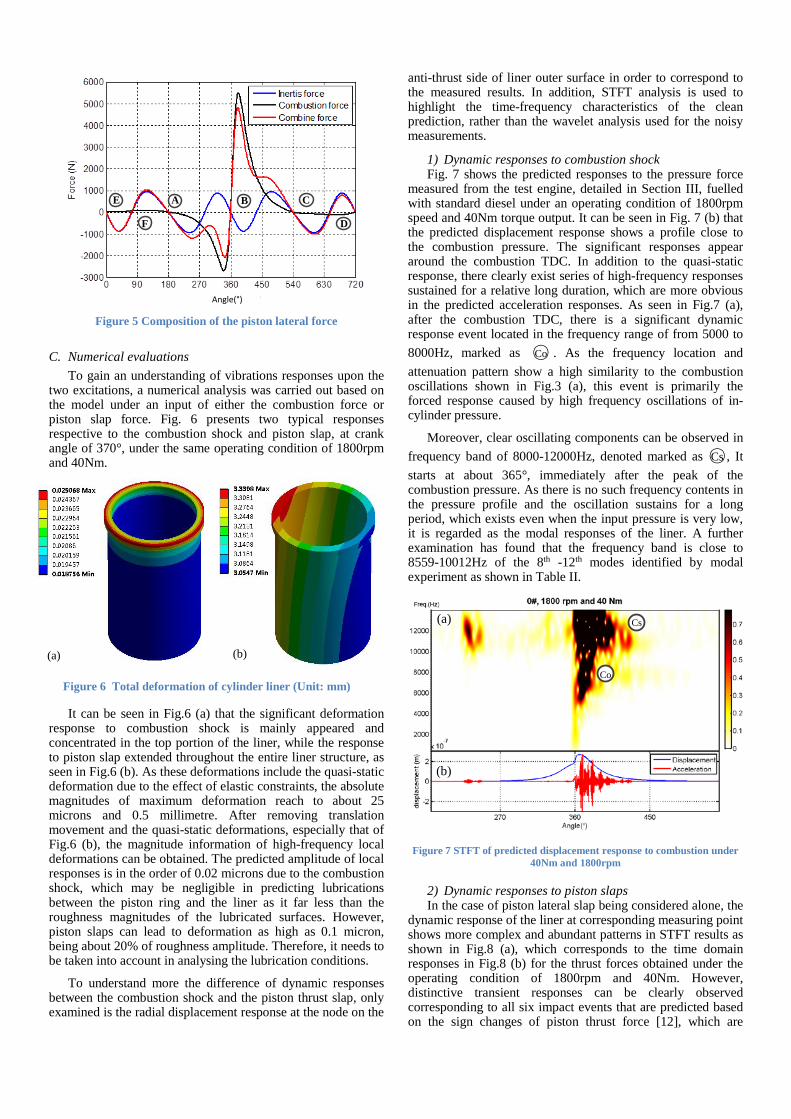
Angle(°)
A B C
D
E
F
Figure 5 Composition of the piston lateral force
C. Numerical evaluations To gain an understanding of vibrations responses upon the
two excitations, a numerical analysis was carried out based on the model under an input of either the combustion force or piston slap force. Fig. 6 presents two typical responses respective to the combustion shock and piston slap, at crank angle of 370°, under the same operating condition of 1800rpm and 40Nm.
Figure 6 Total deformation of cylinder liner (Unit: mm)
It can be seen in Fig.6 (a) that the significant deformation response to combustion shock is mainly appeared and concentrated in the top portion of the liner, while the response to piston slap extended throughout the entire liner structure, as seen in Fig.6 (b). As these deformations include the quasi-static deformation due to the effect of elastic constraints, the absolute magnitudes of maximum deformation reach to about 25 microns and 0.5 millimetre. After removing translation movement and the quasi-static deformations, especially that of Fig.6 (b), the magnitude information of high-frequency local deformations can be obtained. The predicted amplitude of local responses is in the order of 0.02 microns due to the combustion shock, which may be negligible in predicting lubrications between the piston ring and the liner as it far less than the roughness magnitudes of the lubricated surfaces. However, piston slaps can lead to deformation as high as 0.1 micron, being about 20% of roughness amplitude. Therefore, it needs to be taken into account in analysing the lubrication conditions.
To understand more the difference of dynamic responses between the combustion shock and the piston thrust slap, only examined is the radial displacement response at the node on the
anti-thrust side of liner outer surface in order to correspond to the measured results. In addition, STFT analysis is used to highlight the time-frequency characteristics of the clean prediction, rather than the wavelet analysis used for the noisy measurements.
1) Dynamic responses to combustion shock Fig. 7 shows the predicted responses to the pressure force
measured from the test engine, detailed in Section III, fuelled with standard diesel under an operating condition of 1800rpm speed and 40Nm torque output. It can be seen in Fig. 7 (b) that the predicted displacement response shows a profile close to the combustion pressure. The significant responses appear around the combustion TDC. In addition to the quasi-static response, there clearly exist series of high-frequency responses sustained for a relative long duration, which are more obvious in the predicted acceleration responses. As seen in Fig.7 (a), after the combustion TDC, there is a significant dynamic response event located in the frequency range of from 5000 to 8000Hz, marked as
A ○CoE A. As the frequency location and attenuation pattern show a high similarity to the combustion oscillations shown in Fig.3 (a), this event is primarily the forced response caused by high frequency oscillations of in-cylinder pressure.
Moreover, clear oscillating components can be observed in frequency band of 8000-12000Hz, denoted marked as A○CsE A, It starts at about 365°, immediately after the peak of the combustion pressure. As there is no such frequency contents in the pressure profile and the oscillation sustains for a long period, which exists even when the input pressure is very low, it is regarded as the modal responses of the liner. A further examination has found that the frequency band is close to 8559-10012Hz of the 8th -12th modes identified by modal experiment as shown in Table II.
Co
Cs(a)
(b)
Figure 7 STFT of predicted displacement response to combustion under
40Nm and 1800rpm
2) Dynamic responses to piston slaps In the case of piston lateral slap being considered alone, the
dynamic response of the liner at corresponding measuring point shows more complex and abundant patterns in STFT results as shown in Fig.8 (a), which corresponds to the time domain responses in Fig.8 (b) for the thrust forces obtained under the operating condition of 1800rpm and 40Nm. However, distinctive transient responses can be clearly observed corresponding to all six impact events that are predicted based on the sign changes of piston thrust force [12], which are
(a) (b)

marked by A○AE
A to A○FE
A. Moreover, these responses mainly appear at the first three modes, especially for the responses of the impacts without combustion. The 4th modal response can be observable for the impact relating to the combustion. This consistency with modal frequencies demonstrates the FE model developed is acceptable.
Moreover, three more dynamic events, marked as A○GE
A, A○HE
A and A○IE
A, can also be observed in Fig.8 (a). These events correspond to the secondary impacts induced by high amplitudes of thrust force, rather than by a particular force peak, showing that the sustained high-amplitude side-thrust force may also cause additional impacts.
A B C
1st2nd
3rd
4th
HGI
(b)
(a)
D E F
Figure 8 STFT of responses to piston slaps under 40 Nm and 1800Nm
Previous studies [2, 4-5] tend to select a common frequency range of 500-3000Hz, as a rule of thumb, for the detection and analysis of piston slap events. As shown in Fig. 8, the distribution of dynamic responses in the frequency domain shows that the experience-based selection of frequency domain has certain rationality. The origins of this rationality may lie in the inherent mode characteristics of liner structures. As illustrated in the simulation of this study, the dynamic responses excited by piston slaps are mainly concentrated in the frequency range of 600-3500Hz, being close to the frequency band of the first four modes.
III. EXPERIMENTAL VERIFICATION
A. Experimental setup To verify the numerical predictions, experimental studies
were made based on a single-cylinder diesel engine, detailed in Table III. An accelerometer for measuring liner vibrations is installed directly on the external surface of the liner through a waterproof adapter. In addition, in-cylinder pressure, engine speed and time-based crank angle are also recorded for both the FE model calculations and results calibrations. The experimental setup is illustrated in Fig. 9. All the data was recorded simultaneously by a multiple channel acquisition system, and thereafter processed offline for making corresponding comparisons against FE model predictions.
TABLE III. SPECIFICATION OF THE TEST ENGINE
Manufacturer/model Quanjiao Power Co., Ltd., PR. China Engine type QCH1110
Number of cylinders Single
Manufacturer/model Quanjiao Power Co., Ltd., PR. China Combustion system Direct injection
Bore/stroke 110/115 mm Displacement volume 1.093 L
Compression ratio 18:1 Cylinder liners Cast iron replaceable wet liner Rated power 14.7/2400 kW/r/min
Piston clearance 0.5 mm DAQ
Dynamometer
Vib
ratio
n si
gnal
s
Pressure
Ang
ular
spee
d
Control system
Figure 9 A photograph of the diesel engine test rig
B. Diagnostic analysis As the measured vibration contains random noise and
exhibit high non-stationarity, continuous wavelet transform (CWT) was applied to the raw vibration to highlight the vibration responses localised in both the time and frequency domains. In addition, the wavelet result was averaged over 80 engine cycles to suppress noise interferences. Fig.10 presents a CWT result of the liner vibration under the operating condition of 1800rpm and 40Nm. The complicated time-frequency characteristics in Fig.10 (a) can be viewed to have following patterns:
A B CD E F
1st
2nd
3rd
4th
Cs
G HI
Angle(°)
(a)
(b)
Figure 10 CWT of vibration signal under 40Nm and 1800rpm
• The significant responses, marked as A○CsE A, show around the combustion TDC and in the frequency range from 6000 to 9000Hz. Moreover, they can well corresponds to the peak of in-cylinder pressure, which is agreeable with the numerical prediction in Fig.7.
• More distinctive responses, marked as A○AE
A to A○FE
A, corresponds to dynamic events induced by piston

slaps, in Fig.8. These responses appear in the frequency band from 900 to 4000Hz, which associates with the first four modal frequencies.
• Furthermore, three more events predicted in dynamic simulation can be also observed in Fig. 10(a), marked as A○GE
A, A○HE
A and A○IE
A, showing that the sustained high-amplitude side-thrust force can cause repeated impacts, which agrees with that of the established FE model.
Cs
Angle(°)
(a)
(b)
Figure 11 CWT of vibration signal under 10Nm and 1800rpm
Likewise, the time-frequency responses of the liner under lower load show significant patterns due to the combustion, marked as A○CsE A in Fig.11. However, because the combustion is smoother they are in a frequency band from 4000Hz to 7000Hz, which is 2000Hz lower than that of higher load. Moreover, almost all of the slap-induced events above 2000Hz are significantly reduced, showing that the piston movement driven by the smoother combustion is prone to excite more low-frequency mode components.
1st
2nd
3rd
4th
Angle(°)
(a)
(b)
Figure 12 CWT of vibration signal at 40Nm and 1000rpm
At the low-speed of 1000rpm and 40Nm, the CWT result in Fig.12 (a) shows that the amplitudes of all dynamic events are significantly reduced. Only two events around the combustion
TDC and exhaust TDC are still significant. The main reason is that, under low-speed conditions, the kinetic energy of piston lateral movement is dramatically reduced, which leads to a reduction in frequency content of piston side-thrust force.
IV. CONCLUSIONS Based on the comparison between FE model prediction and
experimental evaluation in the form of CWT representation, it can be concluded that developed FE model is acceptable as it provides vibration responses agreeable with measurements. Particularly, the dynamic responses of cylinder liners to combustion excitation appear in a higher frequency modes from 4kHz to 12kHz; whereas that of piston impacts are in a lower frequency modes from 1kHz to 4kHz. Moreover, the responses exhibit short time impulses and are well associated with engine operating strokes. Therefore, they allow correct diagnosis of different vibration sources. Furthermore, the predicted amplitude of local responses is at the order of 0.01 microns due to combustion, which may be negligible to affect lubrications. However, piston slaps can lead to deformation as high as 0.1 micros, being about 20% of roughness amplitude. Consequently, its effect on lubrication performance, friction losses and wear rate of liners will be investigated further.
REFERENCES [1] Hiroshi Kanda, M. Okubo, and T. Yonezawa, ‘Analysis of Noise
Sources and Their Transfer Paths in Diesel Engines’, SAE Technical Paper, Warrendale, PA, SAE Technical Paper 900014, Feb. 1990.
[2] J. R. Cho and S. J. Moon, ‘A numerical analysis of the interaction between the piston oil film and the component deformation in a reciprocating compressor’, Tribol. Int., vol. 38, no. 5, pp. 459–468, 2005.
[3] A. A. Jafari, S. M. R. Khalili, and R. Azarafza, ‘Transient dynamic response of composite circular cylindrical shells under radial impulse load and axial compressive loads’, Thin-Walled Struct., vol. 43, no. 11, pp. 1763–1786, 2005.
[4] H. Murakami, N. Nakanishi, N. Ono, and T. Kawano, ‘New Three-dimensional Piston Secondary Motion Analysis Method Coupling Structure Analysis and Multi Body Dynamics Analysis’, SAE Int. J. Engines, vol. 5, no. 1, pp. 42–50, Nov. 2011.
[5] A. J. Sadowski and J. M. Rotter, ‘Solid or shell finite elements to model thick cylindrical tubes and shells under global bending’, Int. J. Mech. Sci., vol. 74, pp. 143–153, 2013.
[6] E. Wang and T. Nelson, ‘structural dynamic capabilities of ANSYS’, in ANSYS 2002 Conference, Pittsburg, Pennsylvania, USA, 2002.
[7] H. Murakami, N. Nakanishi, N. Ono, and T. Kawano, ‘New Three-dimensional Piston Secondary Motion Analysis Method Coupling Structure Analysis and Multi Body Dynamics Analysis’, SAE International, Warrendale, PA, SAE Technical Paper 2011-32-0559, Nov. 2011.
[8] A. Farshidianfar, M. H. Farshidianfar, M. J. Crocker, and W. O. Smith, ‘Vibration analysis of long cylindrical shells using acoustical excitation’, J. Sound Vib., vol. 330, no. 14, pp. 3381–3399, 2011.
[9] ISO 1083:2004 - Spheroidal graphite cast irons - Classification. [10] H. Wei, J. Wei, and G. Shu, ‘Calculation on cylinder pressure
fluctuation by using the wave equation in KIVA program’, Chin. J. Mech. Eng., vol. 25, no. 2, pp. 362–369, Feb. 2012.
[11] Z. Geng and J. Chen, ‘Investigation into piston-slap-induced vibration for engine condition simulation and monitoring’, J. Sound Vib., vol. 282, no. 3–5, pp. 735–751, 2005.
[12] N. Dolatabadi, S. Theodossiades, and S. J. Rothberg, ‘On the identification of piston slap events in internal combustion engines using tribodynamic analysis’, Mech. Syst. Signal Process., vol. 58–59, pp. 308–324, 2015.