universität paderborn - heinz nixdorf institut · such as a visual editor, to aid their work....
TRANSCRIPT

Universität Paderborn
AG Softwaretechnik
Verwaltung und Nutzung vonKomponentenbibliotheken für
Materialflusssysteme: Konzeption undprototypische Implementierung eines
Werkzeuges
Maintaining and Using Component Libraries forthe Design of Material Flow Systems: Conception
and prototypical Implementation of a Tool
Studienarbeit – Bachelor Thesis
Joel Greenyer
October 2003

Table of Contents
1. Abstract..........................................................................................................................4
2. Introduction....................................................................................................................5
2.1. The Context............................................................................................................5
2.2. Subject of this Thesis............................................................................................. 6
2.3. Beyond the scope this thesis.................................................................................. 9
3. Concept of a Component Library................................................................................ 10
3.1. Basic Elements in a Component Library............................................................. 10
3.1.1. Component Types........................................................................................ 10
3.1.2. Connection Paradigm................................................................................... 11
3.2. Describing the Characteristics of Component Types...........................................12
3.2.1. Models..........................................................................................................13
3.2.2. Specifications............................................................................................... 14
3.3. The Parameter Concept........................................................................................14
3.4. Using a Component Library in a Project..............................................................15
3.4.1. User Defined Component Types.................................................................. 16
3.5. Composed Component Types.............................................................................. 17
4. Library and Project File Structure................................................................................18
4.1. Library File Structure...........................................................................................18
4.1.1. The ports.xml File ....................................................................................... 19
4.1.2. The global.xml File ..................................................................................... 22
4.1.3. The component.xml File ............................................................................. 25
4.2. Project File Structure........................................................................................... 30
4.2.1. The project.xml File .................................................................................... 31
4.2.2. User Defined Component Types.................................................................. 34
5. Introducing the Project Editor......................................................................................35
5.1. The Big Picture: A Developing Environment......................................................35
5.2. Introducing the Project Editor..............................................................................36
5.2.1. Creating a new Project................................................................................. 37
5.2.2. Designing a particular Flow System.............................................................38
6. Implementing the Project Editor..................................................................................41
6.1. Graphical Editor Framework Overview...............................................................41
2

6.1.1. EditParts, EditPolicies, Requests and Commands....................................... 42
6.2. The Model of the Project Editor.......................................................................... 45
6.2.1. The Library Model....................................................................................... 45
6.2.2. The Project Model........................................................................................46
6.2.3. Initialization of the Model in the Editor.......................................................47
6.3. Developing a graphical editor.............................................................................. 48
6.3.1. Collecting General Requirement Information..............................................49
6.3.2. Plugging a GEF Editor into Eclipse............................................................. 50
6.3.3. Assigning EditParts to the Model Objects................................................... 52
6.3.4. The ProjectEditPart...................................................................................... 53
6.3.5. The ComponentInstanceEditPart..................................................................53
6.3.6. The ConnectionInstanceEditPart..................................................................55
6.3.7. Implementing other Features........................................................................56
7. Conclusion................................................................................................................... 59
8. Glossary....................................................................................................................... 61
9. Index of Figures........................................................................................................... 63
10. Appendix................................................................................................................... 64
10.1. Installation Instructions for the project editor....................................................64
10.2. Litrature..............................................................................................................65
10.3. DTD files........................................................................................................... 66
10.3.1. The global.dtd.............................................................................................66
10.3.2. The ports.dtd.............................................................................................. 67
10.3.3. The project.dtd........................................................................................... 68
10.3.4. The component.dtd.....................................................................................69
3

1. Abstract
The design of material flow systems, often complex applications in industry and
business, is a very complicated engineering process and it is important that the
conceptual design phase yields an exact blueprint of the application. To assist the design
process, engineers require a graphical editor that supplies useful results regarding many
aspects of the system, such as the correctness or efficiency of the application.
The aim of this thesis is to provide a method to describe any type of material flow
system in a component library. This library describes the functional standard
components, their interfaces and the paradigms to connect them to each other. A
component library is a construction kit that can be utilized in a graphical editor to design
a certain flow system application.
This approach presents very flexible concepts that will allow to add various, more
detailed descriptions of the components that will consider many characteristics and
functional aspects. This will, in the future, allow to derive useful results from a designed
system layout to support various engineering tasks.
4

2. Introduction
2.1. The Context
In many areas of engineering applications such as logistics, transportation,
manufacturing or traffic flow, the observed dynamic systems can be considered as
material flow systems. These systems often have to satisfy a variety of requirements,
such as time efficiency, limited space and limited resources. Furthermore, these systems
can be very complex and there are many functional dependencies between the individual
elements a system consists of.
Thus, the conceptional design of material flow systems can be a very difficult and time
consuming process, but is nevertheless the most important step in the development of
the respective application. If the design process does not yield a precise blueprint of a
material flow system, it may result in a system that does not meet the requirements or
fails to work at all.
Engineers therefore need a formal model that supports various tasks in the design of the
flow system. Depending on the type of system, it is necessary to consider multiple
aspects of the system. For example, such aspects could be the material flow or the
architectural layout. With this formal model, it should then be possible to analyse and
verify the system in each step of the design process to assure the correctness of the
resulting design.
If engineers had a thorough formal model on different abstraction levels, relating to
different aspects of the system, this could be utilized to achieve additional goals. Firstly,
this model could serve as a basis for a formal or even visual simulation of the system.
Secondly, for example considering manufacturing facilities, the formal model could be
used to derive the control software for the cooperating machinery. And thirdly, this
model could assist in the error detection after the system has been deployed.
To create a concept design and sketch a material flow system, engineers need a tool,
such as a visual editor, to aid their work. Typically, such an editor is used to visually
place and connect functional standard components the system consists of. The following
figure (Figure 1) illustrates an example of how a graphical editor could look like. The
5

connected components shown in this figure could for example be part of an airport's
luggage transport system. The flow of luggage, which is represented by the blue arrows,
enters a scanner on the left that, for example, reads digital tags attached to the luggage.
Depending on the desired destination coded on a tag, the scanner could affect the switch
to set another direction for that piece of luggage. This flow of information to the switch
is represented by the grey arrows. In this example, the switch could also notify the
scanner about each piece of luggage that passed.
2.2. Subject of this Thesis
The subject of this thesis consists of two major parts. The aim of the first part is to
conceptually develop a method to describe any type of material flow system. The second
part will then present a prototypical implementation of a graphical editor that supports
the design of a certain flow system based on this description.
At this point, several fundamental terms are introduced to the reader that will be used
throughout this thesis and are necessary to understand the main focuses.
To describe a particular type of flow system, for example luggage transport systems, it is
necessary to identify the single functional elements a system can consist of and the way
in which these can be connected to each other.
The functional elements that can exist in a flow system, such as the Track, Switch and
Scanner in the luggage transport example (see Figure 1), will be considered as
component types. In fact, many flow systems today consist of standard components that
can easily be identified.
The way in which these component types can be connected to each other will be called
6
Figure 1 - example of a graphical editor
Track01
Switch01Scanner01
Track02
...
...
...

the connection paradigm. The connection paradigm defines a set of connection types.
Each connection type is representing a type of flow in the system. This could for
example be the flow of luggage, information or energy in a luggage transport system.
To connect component types, the component types have to define points that allow a
certain type of connection to be attached. These connection points will be called ports.
A certain arrangement of these ports, which is characteristic for each component type,
will be called an interface. Also part of the connection paradigm is the definition of
certain port types. Every port in the interface of a component type has a particular type,
which implies a certain meaning. In the luggage transport example, there are port types
that represent the in- and outflow of luggage (yellow boxes and yellow circles) and the
in- and outflow of information (grey boxes and grey circles). Thus, the type of port
specifies the types of connections that can be attached, and as in the case of the luggage
transport example, the type of port specifies if the connections start from or lead to these
types of ports.
At this point it is important to emphasize that the examples given so far are already very
specific applications of the concepts that will be presented in this thesis. Port type and
connection types can represent anything and there are no predefined semantics for
example in the shapes of port types. It is possible to describe any type of flow system,
whether it will be luggage transport systems, railway networks or electric circuits.
So far, the parts of information introduced are only the most abstract characteristics that
are necessary to describe a type of flow system. There is yet no way to describe the static
or dynamic characteristics of elements in the system, something that can serve a certain
purpose in the engineering process. To allow this, one or more models can be added to a
component type description. There could, for example, be a Petri Net model included in
each component type of the luggage transport example. The Petri Net could express the
dynamic behaviour of the component, such as the movement of luggage and the
operation of the switch (see Figure 2).
Although, in this thesis, it will not be determined which particular model will be used.
The concepts presented here will provide a way to rather add any desired model or any
desired set of models to each component type. The models also don't necessarily need to
describe a behaviour. It could be possible to include descriptions of shape, 3D-models,
7

or perhaps code written in a programming language. As it will be explained in section
3., the types of models that can be used to serve further purposes in the design process
of a material flow system, will be subject of further research based on this thesis.
The different parts of information that are necessary to describe a type of flow system,
the component type descriptions and the connection paradigm, will be stored in a
component library. Based on the information in a component library it will be possible
to conceptually design certain flow systems. Thus, a component library could be
considered as a construction kit that contains the type specific descriptions about the
elements and rules that exist in a flow system.
A certain flow system, that is designed based on the descriptions in a component library,
will be called a project. A project contains information about instances of component
types and connections between their ports. The connected components in the luggage
transport example as shown in Figure 1 would be an example for a small project or a
part of a project.
The second part of this thesis will present a prototypical implementation of a Project
Editor. The design of a certain flow system based on a component library can be
supported by this graphical editor which is implemented as an Eclipse plug-in and based
on the Graphical Editor Framework (GEF). Section 5. will introduce the features of this
editor and the following section 6. will describe some details of how it was implemented
and how the theoretical concepts mentioned were realised.
8
Figure 2 - the underlying model of a component type
Switch

2.3. Beyond the scope this thesis
The conceptional results of this thesis and the implemented project editor is the
foundation of further research. It is now possible to investigate which models are
suitable to describe the behaviour, shape or other characteristics of the component types.
Yet, one important question will be how it will be possible to derive a complete model
from the connected components in a project, which describes the whole material flow
system (see Figure 3).
This complete model could then serve further purposes. For example, these could be the
analysis, verification or simulation of the material flow system or even the automated
programming of the machinery.
9
Figure 3 - deriving a complete system model from a project
Track01
Switch01Scanner01
Track02
...
...
...
3. Concept of a Component Library
The first part of this this section will introduce the different parts of information needed
to describe a type of material flow system in a component library. In the second part of
this section it will be explained how, based on the information stored in a component
library, a particular system can be described in a project.
The following section (section 4.) will then thoroughly specify the XML file structure in
which a component library and project can be stored.
3.1. Basic Elements in a Component Library
The engineer's approach of describing mechanical or mechatronical systems, one special
type of flow system, is to look at the single elements of the system and the flow of
information, energy and resources between these elements. But, depending on the type
of flow system and the design goals, it might be useful to consider different, more
specific or even more abstract aspects. The concepts introduced in this subsection will
show a flexible approach to describe any type of flow system.
3.1.1. Component Types
The single functional elements that exist in a flow system were already introduced as the
component types. A component of a certain type can be connected to another component
in a characteristic way. The switch in the luggage transport example splits the incoming
flow of luggage into two outgoing flows. The characteristic way in which a component
can be connected to another is called an interface.
The interface of a component type is specified by the particular arrangement of ports
that are connection points allowing the attachment of certain types of connections.
Because this description of a component type will be used in a graphical editor, the
exact positions of the ports will be stored together with the width and height of the
square representing the component type (Figure 4). The ports that exist in the interface
of a component type also have a certain type. The example in Figure 4 shows ports of
different shape and colour, that graphically represent their type. The type of port
specifies the kind of connection types that can be attached to the particular component
10

port. The constraints and rules that specify which types of ports can be connected with
which type of connections are described in the following subsection.
3.1.2. Connection Paradigm
Depending on the particular system and abstraction level, it could be sufficient to
describe the flow of one resource. For example, this could be the flow of luggage in an
airport's logistics facility. In other cases, it could be necessary to distinguish between
multiple flows, for example, between the flow of luggage, an electric flow of
information and a mechanical flow of energy. To visualize different kinds of flows or
signals that can exist in a flow system, different port types and connection types are
necessary. Also, there could be different constraints on how ports need to be connected
to each other. A component library therefore requires a mechanism to cover any types of
connections possible in any kind of flow system. The rules of how to connect which
types of component ports is called the connection paradigm of a component library.
After identifying the component types, it is necessary to identify the port types that exist
in the examined type of flow system and the connection types between them. The
following illustration shows (Figure 5) this in continuation of the luggage transport
system example mentioned above.
11
Figure 5 - the connection types
material flow (luggage)
information flow (electric signal)
flow of energy (hydraulics)
Figure 4 - the description of a component type
PortsSwitchwidth
height

It is not sufficient to define one connection type for each pair of source and target port
types. There should be also other, more complex combinations possible. Therefore it is a
more flexible approach to describe a connection type as something that can connect
ports of a set of source port types to ports of a set of target port types. Additionally, a
connection can be directed or undirected. The following figure (Figure 6) describes the
important information needed for a connection type.
Here it is important to point out that the connection paradigm and its visualization can
be defined flexibly according to the requirements in the system. Also, there is no
predefined meaning in the shape or colour of the ports and connections.
In the connection paradigm, there could be source and target port types that strictly
allow only one connection (0..1). These could for example be hydraulic plugs that allow
to attach only one hydraulic pipe. Also, there could be ports that can symbolize multiple
inputs or outputs (0..n). For example, electrical plugs, that allow wires to carry energy to
multiple destinations. Thus, the number of allowed outgoing and incoming connections
have to be specified for each port type.
For some special occasions, it could be necessary to describe further restrictions or
supply additional information for the connection paradigm. For example, it could be
necessary to express the weight of a connection or other additional parameters. This will
be subject of further investigation in the future.
3.2. Describing the Characteristics of Component Types
The component types and the connection paradigm described above are the most
fundamental elements of a component library. With this information it is now possible
to sketch a flow system layout by instantiating the component and connection types.
But, at this point there is yet no sufficient information about the detailed characteristics
12
Figure 6 - definition of one connection type
Source ports
Target ports
Luggage flowcolor: bluedirected: yes

of the component types or their behaviour in reality. To express this, one or more
models can be added to a component type.
3.2.1. Models
Considering the example of the luggage transport system, there are many aspects and
characteristics of such a system that need to be analysed and evaluated in the
engineering process. Such aspects could for example be the dynamic behaviour, 3D-
shape or architectural layout of the components. Some engineering tasks require the
analysis of the dynamic behaviour on different abstraction levels. The analysis and
verification of a system might consider different aspects than the visual simulation. To
automatically generate the control software of the system's machinery, yet different
information about the components is be required.
To include these different kinds of descriptive information in a component library,
different types of models can be included in the component type descriptions (see
Figure 7).
Types of models are globally declared in the component library. The library specifies a
type of file that contains the model information and which can or has to be referenced by
each component type. Thus, for each component type, there are a number of files that
contain a model. This model could for example coded in XML or a scripting language.
As was said before, this thesis does not specify the exact types of models that will be
used. The concepts presented here rather allow to include any desired model in a
component type description. In fact, for the further topics of this thesis, the exact types
of models will not be relevant. As said in the introduction, if a project has been created
13
Figure 7 - multiple models for a component type
Switch Models

based on a component library, there will be further applications interpreting with the
information provided by the models to derive certain results for the engineering process
of the system. Only these applications have to deal with the included models.
3.2.2. Specifications
In addition to the model, it might be necessary to add restrictions or additional
information about the characteristics or behaviour to a component type. This is done by
including specifications. The way the specifications are included in a component library
is similar to the way models are assigned to each component type. The library globally
defines a set of file types that contain specifications that each component type can or has
to reference. Specifications could contain constraints that, for example, could specify
that only one piece of luggage at a time is allowed on the switch component. For
example a specification could contain CTL formulas (Computation Tree Logic), which
correspond to the behavioural descriptions in the models, such as automata or Petri
Nets.
Again, this thesis does not cover the types of specifications which can be used to specify
the behaviour of a component type, but it will rather be possible to include any desired
type of specification. As already mentioned in the context of models, also the
specifications are only relevant to further applications which interpret these to derive
results for the design process of the system.
3.3. The Parameter Concept
Sometimes component types have some attributes that can differ between one instance
and another. For example, it could be possible to have one track in the luggage transport
14
Figure 8 - model and specification of a component type
Switch
AG | k.track | = 1
model
specification

system that is longer then another. For simulation or construction, it therefore would be
necessary to include a variable (in this example “length”) to the component type, rather
than defining multiple component types. These variables are called parameters. Each
component type can declare a list of parameters that can be or have to be defined for
each instance. The list can also contain the default value that the parameters of the
component type typically have or can be reset to.
For a whole system described in a library, it could be necessary to specify “environment
variables”. These are called the global parameters of a component library. In the
luggage transport system, for example, this could be a global factor “speed” that can be
set for the whole facility. A component library defines a list of these global parameters
which can or have to be set globally for every project utilising this library.
How the parameters affect the models and specifications will depend on the secondary
application interpreting the parameters along with the models and specifications. One
possible approach, if the models are coded in XML, is to include wild card or variable
tags that are marked with a special name space. These tags can be replaced with the
actual parameter value by the time the component type is instantiated or if the created
project is interpreted by another application.
3.4. Using a Component Library in a Project
So far, this section already gave some ideas of what information will be needed in a
project. The following figure (Figure 9) once again shows how a graphical editor could
look like when editing a particular project based on a component library:
15
Figure 9 - example of a graphical editor
Track01
Switch01Scanner01
Track02
...
...
...

A project has to store the following information:
1. A reference to the path of the component library in the file system
2. for each component instance:
a. the type of component
b. the position
c. the parameter values that the type description declared
3. for each connection instances:
a. the type of connection
b. the source port and the component instance starting from
c. the target port and the component instance leading to
d. a list of bend points to allow the custom routing in the editor
For a project, it is not necessary to be concerned about models or specifications. Models
and specifications are type specific and thus stay the same for each component instance.
With the project's information about the position of the component instance and their
connections, there is enough information to derive a model for the complete system
described by a project. Varieties in the models or specifications of component instances
can be expressed by parameters.
Possibly, in the future, the information stored in the models or specification could aid in
the graphical editing process. For example, the information stored in a 2D or 3D model
of a component could imply editing constraints, so that components can only be placed
in a certain distance from each other. How editing feedback be achieved will not be
covered by this thesis. The graphical editor, which will be introduced in section 5. of
this thesis will not yet use any information stored in models and specifications.
3.4.1. User Defined Component Types
In a project, it could sometimes be necessary to add user defined component types,
which are not included in the component library. User defined component types may be
needed just in time of the editing process or are possibly such types that are not usually
16

needed in the library. The project therefore has to provide a way to declare additional
component types that confirm to the connection paradigms in the library. The following
section (section 4) will show how this will be realised similar to the way component
types are declared in a the component library.
3.5. Composed Component Types
If there are basic component types identified for some type of flow system, it should be
possible to define new component types that consist of other component types. These
hierarchically nested constructs would contain component types that are connected with
each other in a certain way and define a set of ports that would assemble a new interface
to the outside
This concept is though not covered by the scope of this thesis and requires further
investigation in the future. A composed component type could be considered as a small
project that defines loose ports as a new interface and undefined parameters as new
parameters for the new composed component type.
For example, with composed components, it would be possible to build up an RS-Flip-
Flop with atomic AND and OR component types. In the luggage transport example, it
could be useful to compose the scanner and switch components to a new component
type if they always tend to appear in this combination (see Figure 10).
17
Figure 10 - example of a composed component type
Switch01Scanner01
ScannerSwitch

4. Library and Project File Structure
This section contains a detailed specification of the XML file structure that is used to
store the component library and a project. This might yet help to better understand the
these two concepts, but all the fundamentals have already been explained in the
previous section (section 3.).
Also, the description of the XML structure already gives a little insight into how the
software, which will be introduced in the following section (section 5), will deal with
the information stored.
The XML file structure is introduced by examples, but in the appendix the DTDs of the
files are listed.
4.1. Library File Structure
The information in a component library is separated into several files. In each
component library there is a ports.xml and a global.xml file. The ports.xml file
contains the definitions of the connection paradigm. That is the definition of the ports
and the connection types. The global.xml contains global definitions for the
component library. This is, for example, the declaration of model and specification types
or global parameters. The component types are defined in sub folders, where in each sub
folder there is a component.xml, which defines the shape and interface of the
component type and the parameters. The implementations of the models and
specifications are stored in the model and specification sub folders of each
component type and are referenced in the component.xml. The following figure
(Figure 11) shows the file structure of the component library in continuation of the
luggage transport example. The code examples shown in this section also correspond to
this example as it was shown before.
18

4.1.1. The ports.xml File
The ports.xml file stores two sets of information. One is the declaration of the
different port types, which a component type can have in its interface. The other set is
the declaration of connection types, which can exist between certain sets of source and
target port types. Also, there is general information the file's header, which contains
information about the author and the version. The following source listing displays an
example:
<?xml version="1.0" encoding="UTF-8"?><ports>
<author>Joel Greenyer</author> <email>[email protected]</email>
<version>1.0</version>
<!-- ~~~~~~~~~~~~~~~~~~~~~~ --><!-- Define port types here --><!-- ~~~~~~~~~~~~~~~~~~~~~~ -->
19
Figure 11 - the component library file structure

<port id="In" minIn="1" maxIn="0" minOut="0" maxOut="0"><name>Luggage Flow In</name><description>
This is the target port representing the inflow of luggage</description><shape>circle</shape><color>FFFFCC</color><border-color>0000FF</border-color><image src="PortIcons/portInIcon.gif"/>
</port><port id="Out" minIn="0" maxIn="0" minOut="0" maxOut="1">
<name>Luggage Flow Out</name><description>
This is the target port representing the outflow of luggage</description><shape>square</shape><color>FFFFCC</color><border-color>0000FF</border-color>
</port>
...
<!-- ~~~~~~~~~~~~~~~~~~~~~~~ --><!-- Define connections here --><!-- ~~~~~~~~~~~~~~~~~~~~~~~ --><connection id="connection1" directed="yes">
<name>Luggage Flow</name><description>
This connection represents the flow of luggage</description><connecting>
<source_type>Out</source_type><target_type>In</target_type>
</connecting><line-color>0000CC</line-color><fill-color>FFFFCC</fill-color><line-style>solid</line-style>
</connection><connection id="connection2" directed="yes">
<name>Electronic signal</name><description>
This connection represents the flow of informationvia electrical wires
</description><connecting>
<source_type>SignalIn</source_type><target_type>SignalOut</target_type>
</connecting><line-color>000000</line-color><fill-color>CCCCCC</fill-color>
20

<line-style>solid</line-style></connection>
</ports>
The Port Type Declaration
Each port definition must provide the following information:
• @id: The unique id of this type of port. This is how it will be referenced later in a
component interface definition or the connection definitions.
• name: A name of this type of port.
Note: In the notation of the component library files, name tags do not uniquely
identify elements. The strings in name tags are intended to be displayed as labels
or tool tips in the software utilizing the component library.
• description: A short description of this type of port.
• shape: The shape can be a specific type of shape: This can either be a circle,
rectangle, diamond or triangle-up, -down, -left, -right.
Note: The domain of values for the shape and some other tags that will be
introduced later is kept small and, if required, can be extended in the future.
• color: The filling colour of the port as a hexadecimal RGB value.
Furthermore there are some optional definitions possible:
• @minIn/@maxIn/@minOut/@maxOut: The number of possible connections going
into and out of this port.
Note: The default is 0..n for incoming and outgoing ports. If a connection attached
at this port is undirected, it will count for both the incoming and outgoing number
of connections.
• border-color: If not specified, the border colour will be #000000, black.
• image: The image element references an image file. If an image is provided, it
will be displayed instead of the shape and colour of the port type.
21

The connection type declarations
The following information is required for each connection:
• @id: The id of a connection. This is the unique identifier of a connection type by
which it will be referenced later.
• name: The name of a connection type.
• description: A short description of a connection type. What it stands for,
which type of flow it symbolises etc.
• connecting: Defines for which pairs of ports this type of connection is valid:
• source_type: The port it is possible to start this connection from.
• target_type: The port into which this connection can end.
Note that a connection also can have multiple source and target port type
elements.
• line-color: The colour of the line which will represent the connection, it is
black by default.
The following values are optional:
• @directed: by default a connection is directed. Note that in a directed="no"
connection there is no semantic difference between the <to>- and <from>- ports.
• fill-color: The filling colour of the arrow tip. If not provided, the arrow tip
will be white, also specified by a hexadecimal RGB-value.
• line-style: The line-style is either dashed or solid as it is by default
4.1.2. The global.xml File
This file stores the global information about a component library. Here, global
parameters are declared as well as the model and specification types each component
type can or has to implement. The global.xml also contains header information such
as the title, the author and the version of the library. The following listing shows an
example of a global.xml file:
22

<?xml version="1.0" encoding="UTF-8"?><global>
<!-- ~~~~~~~~~~~~~~~~~~~ --><!-- general information --><!-- ~~~~~~~~~~~~~~~~~~~ --><title>Luggage transport system component library</title><description>
This is a prototype of a component libraryabstractly describing a luggage transport system.
</description><author>Joel Greenyer</author>
<email>[email protected]</email><version>1.0</version>
<!-- ~~~~~~~~~~~~~~~~~ --><!-- Global Parameters --><!-- ~~~~~~~~~~~~~~~~~ --><global-parameters>
<global-parameter key="global_temp" value-type="int"><name>global speed</name><description>
The global speed factor the system is running at</description><default>10</default>
</global-parameter></global-parameters>
<!-- ~~~~~~~~~~~~~~~~~~~~~~ --><!-- Model type definitions --><!-- ~~~~~~~~~~~~~~~~~~~~~~ --><models>
<model type="PetriNet" required="yes"><name>Petri Net</name><description>
Petri Net model for each component coded in PNML</description><document-type href="schemas/pnml.dtd"/><file-extension>.pnml</file-extension>
</model><model type="Layout" required="no">
<name>Layout</name><description>
Geometric 3D Layout coded in VRML</description><file-extension>.wrl</file-extension>
</model></models>
<!-- ~~~~~~~~~~~~~~~~~~~~~~~~~~~~~~ --><!-- Specification type definitions -->
23

<!-- ~~~~~~~~~~~~~~~~~~~~~~~~~~~~~~ --><specifications>
<specification type="ctl" required="yes"><name>CTL</name><description>
CTL formula for a model</description><document-type href="schemas/ctl.xsd"/><file-extension>.ctl</file-extension>
</specification></specifications>
</global>
The Global Parameters
Any project that makes use of this library has to specify the values of the global
parameter declared here. Each global parameter is declared by the following values:
• @key: The identifier of this parameter.
• @value-type: The value type of this parameter. At the moment, only int and
string values are distinguished.
• name: The name of the global parameter.
• description: A short description of the global parameter.
• default(optional): A default value which is proposed when setting this
parameter.
The Models
As introduced in the last section (section 3), a component type can implement one or
more models. In the global.xml file it is specified which kind of models can or have
to be implemented by each component type. Following elements are necessary in a
model declaration:
• @type: The identifying name of the model type.
• name: The name of this model type.
• description: A short description. What aspects are described, which method or
formalism is used, etc.
24

• file-extension: The type of file such a model type can be found in. To
provide this model to a component (as will be explained later in the
component.xml section), a file with this extension has to be referenced in the
component. Different models can have the same file extension, i.e. “.xml”.
Following elements are optional in a model declaration:
• @required: By default a model is required.
• document-type: A model file in each component must conform the schema or
dtd referenced here.
The Specifications
The specifications-section is similar to the models-section. Again, the global.xmlonly contains the declaration of each specification a component can or must reference in
its component.xml file.
Following elements must be included in a specification declaration:
• @type: The identifying name of a specification type.
• name: The name of this specification.
• description: A short description.
• file-extension: The type of file such a specification type can be found in.
Following elements are optional in a specification declaration:
• @required: By default a specification is required for each component.
• document-type: A specification file in each component must conform to the
schema or DTD referenced here.
4.1.3. The component.xml File
In each sub folders of the component library directory, there is a component type
defined by the component.xml file. It is useful to name the sub folders equal to the
name of the component type, but not necessary. The following listing shows an example
of the switch in the luggage transport system:
25

<?xml version="1.0" encoding="UTF-8"?><component id="Switch">
<!-- ~~~~~~~~~~~~~~~~~~~ --><!-- general information --><!-- ~~~~~~~~~~~~~~~~~~~ --><title>Switch</title><description>
This component is a switch with one entry and two exits.Also, there is a target information port which allowsto set the direction of the switch and a sourceinformation port notifying attached components abouteach peace of luggage that passes.
</description><author>Joel Greenyer</author>
<size width="130" height="100"/><color>FFCC99</color><border-color>294563</border-color><image scr="switch.gif"/>
<!-- ~~~~~~~~~~~~~~~~~~~~~~~~~ --><!-- interface/port definition --><!-- ~~~~~~~~~~~~~~~~~~~~~~~~~ --><interface>
<port type="In" id="In-Port" x="10" y="50"><name>In Port</name><description>Single luggage flow entry</description>
</port><port type="Out" id="Out-Port1" x="120" y="25">
<name>Out Port 1</name><description>right luggage flow exit</description>
</port><port type="Out" id="Out-Port2" x="120" y="75">
<name>Out Port 2</name><description>light luggage flow exit</description>
</port><port type="SignalIn" id="SignalIn1" x="80" y="90">
<name>Signal In Port 1</name><description>
Information port that allows toset the direction of this switch
</description></port><port type="SignalOut" id="SignalOut1" x="100" y="90">
<name>Signal Out Port 1</name><description>
Information port that notifies attachedcomponents about pieces of luggage that pass
</description>
26

</port>
</interface>
<!-- ~~~~~~~~~~~~~~~~~~~~~~ --><!-- Parameters declaration --><!-- ~~~~~~~~~~~~~~~~~~~~~~ --><parameters>
<parameter key="lenth_incoming" value-type="int" required="yes"><name>Lenth Incoming Track</name><description>
Lenth of the incoming luggage transport track, the distancebetween the starting point and the braching of the tracks
</description><default>2</default>
</parameter><parameter key="lenth_outgoing_right" value-type="int" required="yes">
<name>Lenth Left Outgoing Track</name><description>
Lenth of the left outgoing luggage transport track, the distance between the branching of the tracks and the endof the outgoing left track.
</description><default>2</default>
</parameter><parameter key="right_outgoing_right" value-type="int" required="yes">
<name>Lenth Right Outgoing Track</name><description>
Lenth of the right outgoing luggage transport track, the distance between the branching of the tracks and the endof the outgoing right track.
</description><default>2</default>
</parameter></parameters>
<!-- ~~~~~~~~~~~~~~~~~ --><!-- Model declaration --><!-- ~~~~~~~~~~~~~~~~~ --><models>
<model type="PetriNet" href="Models/switch.pnml"><name>Petri Net</name><description>Petri Net model for the switch</description>
</model><model type="Layout" href="Models/switch.vrml">
<name>Layout</name><description>Geometric 3D Layout of the switch</description>
</model></models>
27

<!-- ~~~~~~~~~~~~~~~~~~~~~~~~~~ --><!-- Specifications declaration --><!-- ~~~~~~~~~~~~~~~~~~~~~~~~~~ --><specifications>
<specification type="ctl" href="Specifications/switch.xctl"><name>CTL</name><description>CTL formula for a model</description>
</specification></specifications>
</component>
Each component definition has to provide some general information:
• an @id: the unique identifier of a component type
• a title
• a description
• the author
• a size: The @width and @height of a component.
• a color: The fill colour of a component.
• a border-color: (optional) the border colour of the component's rectangle. The
default border is black if no border-colour is provided.
• an image: If provided, an image is displayed in the centre of the component.
Note: This feature is not yet supported by the Project Editor introduced in
section 5.
The Interface Definition
The interface of a component is the definition of the specific ports the component
implements and where they are located.
The list of ports must specify:
• @type: The type of port as declared in the ports.xml file.
• @id: The id of this port. This id will be referenced later.
28

• @x, @y: The position of a port relative to the top left corner of the component.
• name: The name of the port.
• description: (optional) A short description of this port in the interface of the
component type.
The Parameters Declaration
The parameters section holds a list of parameters which can or have to be defined in
each instance of this component.
Each parameter declaration must provide the following information:
• @key: The identifier of this parameter.
• @value-type: The value type of this parameter. For now, only int or string
values are distinguished.
• @required: (optional, default is "yes") specifies if it is necessary to explicitly set
the value of this parameter for every instance of this component.
• name: The name of this parameter.
• description: A short description of this parameter.
• default: A default value that will be proposed when specifying this parameter.
The Models declaration
In this section a component type defines and references its specific models that it can or
has to implement as declared in the library's global.xml file. All model definitions
need to provide the following information:
• @type: The identifying name of this model type. If there are models of a specific
type defined in the global.xml file, one model in the component's declaration
must be of that type.
• href: The reference to the model file
• name: The name of this type of model
• description: A short description
29

The Specifications Declaration
As with the models, each component declares and references its specifications. All
declarations of these specifications need to provide the following information:
• @type: The identifying name of this specification type. If there are specifications
of a specific type defined in the global.xml file, one specification must be of
that type.
• href: The reference to the specification file
• name: The name of this type of specification
• description: A short description
4.2. Project File Structure
A project always references a component library and describes a certain system build up
by the component types in this library. These sets of information are stored in a
project.xml file.
• the component instances and parameter value definitions
• the connections between the ports of these component instances
• a global parameter value definitions
• user defined component types
A project file system could look like the example in the following figure (Figure 12):
30
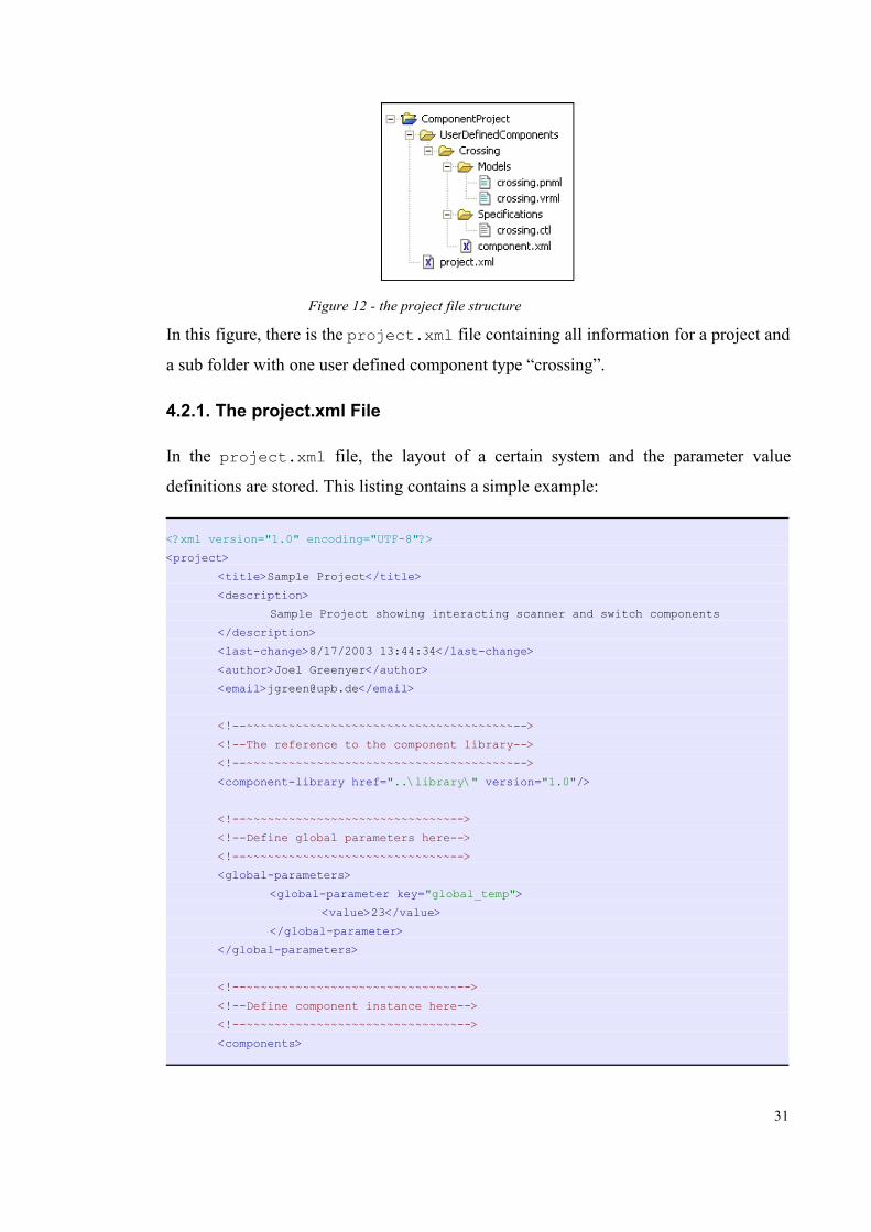
In this figure, there is the project.xml file containing all information for a project and
a sub folder with one user defined component type “crossing”.
4.2.1. The project.xml File
In the project.xml file, the layout of a certain system and the parameter value
definitions are stored. This listing contains a simple example:
<?xml version="1.0" encoding="UTF-8"?><project> <title>Sample Project</title>
<description>Sample Project showing interacting scanner and switch components
</description><last-change>8/17/2003 13:44:34</last-change><author>Joel Greenyer</author><email>[email protected]</email>
<!--~~~~~~~~~~~~~~~~~~~~~~~~~~~~~~~~~~~~~~--><!--The reference to the component library-->
<!--~~~~~~~~~~~~~~~~~~~~~~~~~~~~~~~~~~~~~~--> <component-library href="..\library\" version="1.0"/>
<!--~~~~~~~~~~~~~~~~~~~~~~~~~~~~~--><!--Define global parameters here--><!--~~~~~~~~~~~~~~~~~~~~~~~~~~~~~--><global-parameters>
<global-parameter key="global_temp"><value>23</value>
</global-parameter></global-parameters>
<!--~~~~~~~~~~~~~~~~~~~~~~~~~~~~~~--><!--Define component instance here--><!--~~~~~~~~~~~~~~~~~~~~~~~~~~~~~~--><components>
31
Figure 12 - the project file structure

<component type="Switch" id="Switch001"><name>Switch 1</name><description>Cool Switch</description><position x="474" y="114"/><parameters>
<parameter key="speed_out"><value>150</value>
</parameter><parameter key="speed_in">
<value>50</value></parameter>
</parameters></component><component type="Track" id="Track0002">
<name>Track 2</name><description>description</description><position x="177" y="94"/><parameters/>
</component></components>
<!--~~~~~~~~~~~~~~~~~~~~~~~~~~~~~~~~--><!--Define connection instances here--><!--~~~~~~~~~~~~~~~~~~~~~~~~~~~~~~~~--><connections>
<connection type="connection1" id="connection10002"><source component-id="Switch001" port-id="Out-Port1"/><bendpoint x="405" y="139"/><bendpoint x="405" y="119"/><target component-id="Track0002" port-id="In-Port"/>
</connection></connections>
</project>
In the header, this file stores some general information:
• title: The project's title.
• last-change: The date of the last time the project was saved.
• author: The author of the project.
• email: The authors email address.
• note: A general note about this project.
• component-library:
32

• href: This attribute contains a reference, the path to the component
library this project is based on.
• version: Notes the current version of the component library the project
is based on. The project editor will produce a warning message, if the
version in the project file does not match the version in the global.xmlfile.
The Global Parameters
The global parameters, which were declared in the global.xml file, now have values
assigned to them in this section. Each global_parameter definition provides
following information:
• @key: The identifying key of this parameter as declared in the global.xml file.
• value: The value of this parameter
The Components
In the components section, there is the component instances are defined. Each definition
has to specify the following values:
• @type: The type name of the instantiated component.
• @id: The identifying id of this component instance.
• name: The name of the component instance.
• description: A short description of the component instance.
• position: The two attributes @x and @y specify the position.
• parameters: The defined parameters of the instance. Each parameter element
holds a key-value pair.
The Connections Section
Here each connection between one component's port and another component's port is
stored. Each connection provides the following information:
• @type: The type of connection used, as defined in the ports.xml file.
33

• source and target: The component and port this connection starts from or ends
in.
• @component-id: The id of a component instance defined above in the
components section
• @port-id: The id of a component instance's port as defined in the
component.xml file
4.2.2. User Defined Component Types
In a project, it is possible to define user defined component types in addition to the types
defined in the component library. These user defined component types have to be stored
in a sub folder of the project called UserDefinedComponents. In sub folders of this
folder, component types can be defined exactly the same way as in a component library.
The user defined components have to be based on the same connection paradigm the
rest of the library is based on and have to implement the model and specification types
that have been declared as mandatory in the library's global.xml.
34

5. Introducing the Project Editor
The second part of this thesis describes the prototypically implemented graphical editor,
which enables the design of flow system projects based on a component library by using
the concepts described so far.
This section will introduce the features of this editor and how it is intended to be
integrated in a larger developing environment in the future. The following section
(section 6) will then give a little insight in how this editor was implemented as an
Eclipse plug-in using the Graphical Editor Framework (GEF).
5.1. The Big Picture: A Developing Environment
In order to allow an efficient design of material flow systems, there has to be software,
which supports the concepts introduced in the preceding sections. This software could
for example be integrated into a developing environment as illustrated below:
In the first stage, as illustrated in the diagram, the creation of component libraries has to
be supported by a Component Library Editor. With this editor it should be possible to
create component types and define the connection paradigm. Also the Library Editor
should include tools to create models and specifications for the component types.
35
Figure 13 - a developing environment for flow systems
Model Editor Component type Editor SpecificationsEditor
Library Editor
Project Editor
Analysis and Verification
Simulation andVisualization
Programming thecontrol software
...
Component Library
Project

Companies that produce components or machinery for a specific kind of material flow
systems, for example the luggage transport system, would be able to use this editor to
provide a component library for a system consisting of their products.
The Project Editor is then used to design such a particular system. After a library is
stored in a file format as described in section 4., it will be possible to design a particular
system layout in a project, based on the component library. This Editor would for
example be used by the engineers developing a certain luggage transport system. The
project editor will provide a canvas to place and connect the component instances,
following the rules of the connection paradigm. Also, for each component instance and
the project, it will be possible to define the parameters and global parameters declared in
the library. The project editor, which was prototypically implemented within the scope
of this thesis, is thoroughly described in the following section (section 6.).
After the project is stored in a file format as described in section 4., there could be
various further applications interpreting the underlying models of the connected
components. As already pointed out in preceding sections, depending on the model,
further tasks will be for example the analysis and verification of the system, the
automated programming of control software or the simulation and visualization of the
system.
5.2. Introducing the Project Editor
The project editor, as prototypically implemented within the scope this thesis, allows the
design of a particular flow system, based on the component types and the connection
paradigm definitions in a component library. With the editor, it is possible to create a
new project based on an existing component library and to save the designed system in
the file format as specified in section 4. This section will give an introduction to the
features of this project editor and how it can be used to create, edit and save a project.
36

The project editor is implemented as an Eclipse plug-in. Eclipse is a platform for any
kind of software tools. The tools are contributed to a workbench as plug-ins and can
assemble to any imaginable application. There is further information about Eclipse in
section 6. and in the literature listed in the Appendix.
5.2.1. Creating a new Project
In the Eclipse environment the term project is also used for top level working sets of
files and folders that exist in the Eclipse workbench. A component project, however, is a
project.xml file, sometimes with a sub folder containing the user defined component
types. Thus, there can be several component projects in one Eclipse project.
37
Figure 15 - selecting the Component Project File Wizard
Figure 14 - the project editor implemented within the scope of this thesis
Project Editor
Component Library
Project

To create a new project file, it is essential to supply a valid component library. The
project editor supplies a wizard, which allows the selection of a library's global.xmlfile in a file browser dialogue. Also, some header information can be entered into the
wizard. The figure below (Figure 16) shows some example values entered:
If a valid component library is referenced, the wizard will create an empty project and
open the project editor.
5.2.2. Designing a particular Flow System
The screenshot below shows the Eclipse environment, when editing a project with the
project editor.
38
Figure 16 - example values entered in the Component Project File Wizard

On the left (1), there is the resource navigator, which is a default plug-in of Eclipse.
This navigator can be used to browse through the eclipse projects and to open files, such
as the component projects. The project editor plug-in (2, 3) is the actual editor. It
provides a canvas (2) to sketch a particular system layout, and a palette (3) that provides
the component types and connection types available in the underlying component
library. The Properties View (4) is also a default plug-in of Eclipse which shows the
properties of selected objects and allows them to be edited.
39
Figure 17 - different parts of the project editor

To design a particular system layout, it is possible to select the components in the
palette and to place them on the canvas. According to the connection paradigm defined
in the component library, it is then possible to connect the component ports with the
connections available in the palette. All existing objects can be moved on the canvas
and they can be deleted again. It is also possible to add bend points to the connections to
route them along a custom path. Bend points can be deleted by moving the bend point
back, so the line is straightened again. Components and connections on the canvas can
be selected with the selection and marquee tool in the top of the palette. For every
editing action, the editor supplies full undo/redo functionality.
If an object is selected on the canvas, additional information is shown in the Properties
View. Some of the entries, for example the name, description or parameters of a
component instance, can be edited. When no object is selected, the user clicked on the
canvas, the properties of the project are shown. Then it is, for example, possible to edit
the global parameters.
40

6. Implementing the Project Editor
This section will explain how the Project Editor was implemented as an Eclipse plug-in
using the Graphical Editor Framework (GEF). Eclipse is a universal tool platform that
allows to integrate plug-ins which can assemble to almost any imaginable application. It
is “an open, extensible IDE for anything, but nothing in particular”1. The Graphical
Editor Framework, which is a separate subproject within the Eclipse project, can be
optionally integrated into Eclipse as a plug-in and supports the development of graphical
editors.
6.1. Graphical Editor Framework Overview
The Graphical Editor Framework (GEF) is a framework, which supports the
development of graphical editors and is itself an Eclipse plug-in. Today, there are
already many professional editors based on GEF, for example, an UML-editor2 or
editors to design electrical circuits. The framework is following the Model-View-
Control paradigm (MVC), which is a common approach to separate concerns into
different software components. The Model software components are responsible to
represent the problem domain, the aspect of reality the application is dealing with. The
Controller components perform the changes on the Model components that result from
user interactions or other occurring events. Finally, the View components graphically
present the software Model to the user and provide possibilities for the user to interact
with the software. Strictly following the MVC paradigm results in a modular software
architecture that can be extended easily. Due to this paradigm, the GEF framework is
very flexible and almost any software model of structured components and connections
can be supplied with a graphical editor user interface. GEF already includes many
editing features and ways to graphically display the data. GEF utilizes the draw2D-API,
which is a very comprehensive 2D-API based on SWT (Standard Widget Toolkit).
1 See www.eclipse.org
2 See www.eclipseuml.com
41

6.1.1. EditParts, EditPolicies, Requests and Commands
At the point of introducing EditParts, EditPolicies, Requests and Commands, it is
presumed for this subsection, that the software model of the application already exists.
The model, the structured internal representation of the problem domain, will be
covered by the following subsection (section 6.2.). For now, the model of a project is a
certain data structure as illustrated below (Figure 18):
An EditPart is assigned for every object in the model that will be displayed. An EditPart
is the GEF representation of a model object and is responsible for several tasks: Firstly,
the EditPart has to provide the graphical draw2D figure to be displayed. Secondly, the
EditPart acts like an interface to delegate editing requests to the model. And thirdly, the
EditPart has to manage the visualization of feedback to the user interactions. All model
objects are mapped to a hierarchy of EditParts as shown in the next figure (Figure 19):
The top EditPart in the hierarchy, for example, corresponds to the model object of the
whole project that contains all the component and connection instances. One level
below, all the component and connection instances are mapped to one EditPart each. A
continued hierarchy with more levels of EditParts would for example be needed to
42
Figure 18 - the model of a component project
connection instances
component instances
Figure 19 - mapping of model objects to a hierarchy of EditParts
Model EditParts

describe nested components. In a UML-editor this would for example be classes nested
in a package container component.
As described above, the EditParts correspond to fairly different model objects.
Connection instances should not only look different to component instances, the
possible editing actions are fairly different, too. There are specific types of EditParts, for
example the AbstractGraphicalEditPart or the Abstract-ConnectionEditPart, that need to be implemented for different special model
objects. But the different EditParts are only needed by the framework to maintain the
hierarchy of EditParts or to handle the refreshing of visuals. These special EditParts do
not determine a specific editing behaviour.
To describe a certain type of editing behaviour, the different EditParts have to reference
specific Roles. Roles are predefined string constants of the GEF framework, that, when
referenced, imply a certain behaviour of the EditPart. There is, for example, a
COMPONENT_ROLE for components and a CONNECTION_ROLE for connections.
The way of how the EditParts behave in different Roles is not hard coded. An EditPart
has to implement specific EditPolicies that correspond to a certain Role. An EditPolicy
provides rules of how and if an object will be able to respond to a particular editing
Request. For example, to delete a component, the corresponding EditPart has to install
an EditPolicy that deals with the delete request. For every Role, there are EditPolicy
classes, that can or have to be subclassed to implement the specific behaviour. The
following figure describes EditPolicies implemented by an EditPart:
The reason why EditParts have to be implemented for specific Roles, is to allow an easy
replacement of EditPolicies. Subclasses of the EditParts may need to replace
43
Figure 20 - EditPolicies implemented for different roles by an EditPart
§§
§§
...EditPart EditPolicies
COMPONENT_ROLE
GRAPHICAL_NODE_ROLE

EditPolicies, or sometimes an EditPart may need to choose or swap a particular
EditPolicy dynamically for the same Role. GEF allows the set of Roles and EditPolicies
to be extended for custom purposes.
If there is a specific editing request sent to the EditPart, the EditPart iterates over all
implemented EditPolicies until one EditPolicy handles the request. Requests that don't
apply to a particular EditPolicy will be ignored and if no EditPolicy implemented will
handle a request, the request will be completely ignored by the EditPart.
Now, if there is an EditPolicy responsible to handle a request, there are two things that
have to be done: Firstly, the underlying model has to be changed according to the
editing request. And secondly, the changes have to be visualized in the editor.
The changes to the underlying model object are performed by Commands. An
EditPolicy creates a Command for every change upon a model object. A single
Command object stores the information of the editing step they performed on the model
and it stores the manner in which the editing step can be reversed. GEF stores the
Commands on a stack, so that a complete undo/redo functionality can be easily
implemented. The reversion of an editing step can be simple, for example if a bend
point is added to a connection, it can be easily removed again, because only the one
connection instance was affected. But it might be much more complex, for example, to
reverse the deletion of a component. If the deletion results in also deleting the appended
connections, there are several elements that need to be deleted, stored and restored again
on demand.
The last step, the visualization of the performed changes, is initialized by listeners. The
model objects notify their EditPart of the type of change that was done to them.
Depending on that type of change, the EditPart is responsible for changing labels,
positions and refreshing the visuals.
44

6.2. The Model of the Project Editor
This section will describe the structure of the software model, which will represent the
component library and the project that is used internally by the graphical editor. The
next subsection (section 6.3.) will then describe how a graphical editor can be
implemented based on this software model.
In fact, the model described here, can be taken as a blueprint for any model that has to
serve as the basis for a graphical editor in GEF. The model is simple and divided in the
type specific information – the library contents – and the instance specific information
– the project contents –, which gives a good separation of concerns. For more specific
uses, this software model can be extended and customized easily.
For a better understanding, in this and the following subsections, the description of the
software will be simplified. Consider the JavaDoc for a detailed documentation of the
source code. Also, the software components and their dependencies described here, are
very closely related to the concepts described previously in section 3.
6.2.1. The Library Model
As shown in Figure 22, the software model of a component library is a very close
counterpart to the concepts described in section 3.
In the middle of the class diagram, there is the library class which contains the
45
Figure 21 - Commands performing changes on the model
REQ_DELETE §§
§§
...
REQ_DELETE
createDeleteCommand

definitions of the component types and the port and connection types. The port and
connection type definitions, as explained earlier, make up the connection paradigm. A
connection of a certain type can connect ports that are in a set of source port types to
ports that are in a set of target port types. The library, as well as the component types,
have parameter declarations. The parameters declared in the library are the global
parameters. A component type consists of an component interface which itself consists
of a certain arrangement of component ports. Component ports can be considered as
instances of port types. So every component port has a certain port type.
6.2.2. The Project Model
The structure of the project's software model is also very closely related to the concepts
described in section 3. The package at the top of the diagram is an abbreviated
representation of the library class diagram shown above. In fact, the real package name
chosen in the implementation for the library model classes is
de.upb.swt.components.library.core. Some classes of the project package are
46
Figure 22 - class diagram of the library model

associated with classes of these package, because there the type specific data is stored.
A project, which is based on a library, defines the global parameters that were declared
in the library. Furthermore, a project contains of a collection of component instances
and a collection of the connection instances between these. The way in which a
particular source and target port is specified for a connection instance is hard to see from
this diagram alone. As shown, a connection instance has a reference to the source and
target components, but the connection instance has also has a reference to the specific
source and target component ports that are specified in the interface of the component
type description. These two parts of information exactly define a certain source and
target port in a certain component instance.
6.2.3. Initialization of the Model in the Editor
The model, as described in the preceding subsections, has to be initialized at start-up of
the editor. To initialize means to read the library and project information stored in the
XML files as described in section 4. and to translate it in a model object structure.
Following list defines an appropriate order:
47
Figure 23 - class diagram of the project model

1. Reading the project's header information, most importantly the reference to the
library.
2. Loading the component library.
a) Reading the information from the global.xml file (header information and
global parameters)
b)Reading the information from the ports.xml file (port type and connection type
definitions)
c) Reading the information of all component.xml files found in the sub folders
(header information, size, look, parameters)
3. Reading the rest of the project:
a) Add user defined component types to the library object structure
b)Load global parameters
c) Load component instances
d)Load connection instances
6.3. Developing a graphical editor
Now, that the model part of the editor has been created, the development of the GEF
part of the graphical editor can begin. First, some general information should be
collected: How will the component types look like and which editing actions should be
possible with the editor? It is helpful, but not necessary to know a little about the
draw2D-API and the possibilities of GEF at this point. After that, the EditParts,
EditPolicies and Commands can be implemented. This will, however, not be possible to
be done sequentially, as it is explained in this section. The EditParts and the EditPolicies
will rather need to be implemented one by one in a cyclic way, because in this process it
is important to check the result after each step and to consider how the next feature will
have to be realized depending on the work done up to this point. A common way for this
kind of editor is to implement the EditParts for the component instances first. Then the
anchors can be added to them, the GEF representation of the component ports. Later, the
48

EditParts for the connection instances can be created.
The Appendix contains a list of references to helpful documents regarding the
development of Eclipse plug-ins and GEF Applications.
6.3.1. Collecting General Requirement Information
For a rather simple editor, such as the project editor, it might not be necessary to
accurately collect the information about the visual occurrence of objects or the possible
editing actions. But for larger projects, where the use cases become more complex or the
requirements for the graphical representation of information has to be optimized for the
user, such a requirement list should be set up before engineering the architecture of the
editor's controller and view part in detail. This subsection will give a feeling for what
the editor should be capable of.
Displaying a Component Instance
A component instance should be displayed as a rectangle with
– the dimensions and colours specified in the component type description
– a label containing the instance's name
– the ports of the shape and the positions described in the component type's interface
definition.
Displaying a Connection Instance
A component instance is a line or an arrow
– with the the colours specified in the connection type definition
– with the bendpoints specified in the instance description.
– going from a certain source port to a certain target port
Possible Editing Actions
The possible editing actions should be:
– Placing, moving, deleting component instances
– drawing connection instances between certain types of ports as specified in the
49

library's connection paradigm
– adding, moving and deleting connection instance bendpoints
– reconnecting and deleting connection instances
– edit the object's attributes (i.e. parameters, names, descriptions) in the PropertyView
of Eclipse
6.3.2. Plugging a GEF Editor into Eclipse
As said before, every tool in Eclipse is integrated as a plug-in. For each kind of plug-in,
Eclipse supplies certain extension points, which, in order to plug in a tool, need to be
provided with a main plug-in class. Depending of the type of plug-in, the provided class
has to implement a certain interface. For example, an editor that extends the
org.eclipse.ui.editors extension point, has to implement the IEditorPartinterface. More information about the extension points can be found in the Eclipse
online help, in the Platform Plug-in Developer Guide. (see Appendix)
The plugin.xml file
On start-up of the Eclipse platform, the plug-in configuration files, the plugin.xmlfiles of all plug-ins will be loaded. For example, possible dependencies to other plug-ins
or the location of the main plug-in class are stored in these configuration files. The
plugin.xml file of the Project Editor looks like this:
<?xml version="1.0" encoding="UTF-8"?><plugin id="de.upb.swt.components.project"name="Component Project Editor" version="0.3.0"> <runtime> <library name="project.jar" /> </runtime> <requires> <import plugin="org.eclipse.gef" /> <import plugin="de.upb.swt.components.library"/> </requires>
<extension point="org.eclipse.ui.editors"> <editor name="Project Editor" icon="icons/project_editor.gif" filenames="project.xml" class="de.upb.swt.components.project.editor.ProjectEditor" id="de.upb.swt.components.project.editor.ProjectEditor"></editor> </extension>
50

</plugin>
Each plug-in provides a .jar file that contains the byte code of the plug-in. This jar file
is referenced in the <runtime>-section. Below that, the <requires>-section lists the
plug-ins this editor plug-in depends on. This dependency has to be included any time the
plug-in uses the libraries of other plug-ins. In this case, the editor depends on the GEF
plug-in and the de.upb.swt.components.library plug-in, which contains the
packages with the same name prefix. The library packages also contain the library
model classes as introduced in subsection 6.2.1. It is possible to separate the code of one
application in several plug-ins right from the beginning. This editor is separated into a
library plug-in an the actual editor plug-in, because the library part will also be needed
in other applications in the future, for example the library editor. The Library Editor
itself will not need classes of the project editor. The library plug-in does not contain any
executable plug-in, it just contributes the libraries.
In the <extension> section below, now actually the editor is plugged into the
workbench. The editor is supposed to open files with the name project.xml and the
main editor class is de.upb.swt.components.project.editor.-ProjectEditor.
The ProjectEditor Class
The ProjectEditor class is derived from org.eclipse.gef.ui.parts.-GraphicalEditorWithPalette, which is one standard implementation of the
org.eclipse.ui.IEditorPart interface. This class is i.e. responsible for the
initialization and shut-down of the editor as well as for handling the saving of the edited
files.
During initialization, many things happen: Firstly, the model object is created form the
files as described in subsection 6.2.3. Secondly, some general attributes are set for the
the graphical viewer and, thirdly, the model objects are provided to the graphical viewer
along with a factory class that will create the corresponding EditPart instances. This will
be described in the following subsection. The graphical viewer of a GEF editor is an
implementation of the org.eclipse.gef.EditPartViewer interface provided by
51

the GEF framework. A graphical viewer displays the EditParts on a canvas and is
responsible for managing selections, focuses on objects and the routing of mouse inputs
and keystrokes to the EditParts.
6.3.3. Assigning EditParts to the Model Objects
During initialization, the project object, the root object of the software model loaded
from the files, is handed over to the graphical viewer of the editor along with the
EditorsGraphicalPartFactory class. This class creates the hierarchy of EditParts as
described in subsection 6.1.1. This is done by the following method:
public EditPart createEditPart(EditPart context, Object model) {
EditPart editPart = null;
if (model instanceof ComponentInstance) { editPart = new ComponentInstanceEditPart();}else if (model instanceof ConnectionInstance) { editPart = new ConnectionInstanceEditPart();}else if (model instanceof Project) { editPart = new ProjectEditPart();}
if (editPart != null) { editPart.setModel(model);}
return editPart;}
When the project object, the root model object, is handed over to the graphical viewer, a
corresponding ProjectEditPart is instantiated. This EditPart implements a
getModelChildren() method, that then returns a list of the component instances
referenced in the project. The method listed above then again iterates over this list of
model objects and assigns the corresponding EditParts.
The ComponentInstanceEditPart is a subclass of an AbstractGraphical-EditPart, that provides support for objects that can have connections attached to
them. These EditParts implement a different way to obtain attached connection instance
52

model objects. They implement the methods getModelSourceConnections() and
getModelTargetConnections(). Again, the method listed above iterates over all
the model objects and assigns the EditParts.
Which methods of the EditParts are called and how the method above is called to iterate
over the lists of model objects is handled by the GEF framework. It is only necessary to
provide correct implementation of the getModel-methods.
6.3.4. The ProjectEditPart
The ProjectEditPart corresponds to the root object in the software model, the
project object, which contains all other component and connection instances. This
EditPart in the graphical editor is therefore responsible to provide the canvas where the
other contained objects can be edited.
The graphical figure, that this EditPart has to provide, is a layer on that other graphical
objects can be placed. In this case it's a FreeformLayer provided by the draw2D API.
The Role appropriate to this kind of EditPart is the LAYOUT_ROLE. This Editor acquires
this Role by implementing a subclass of a XYLayoutPolicy. LayoutPolicies are
responsible for managing editing actions like moving, resizing and creating child
objects. For each of these actions, the ComponentXYLayoutPolicy creates certain
Commands that perform the changes on the model objects. For example, there is the
ComponentInstanceConstraintCommand, that handles the moving of components
or the ComponentInstanceCreateCommand, that will create another component
instance.
6.3.5. The ComponentInstanceEditPart
The ComponentInstanceEditParts corresponds to component instance model
objects. These EditParts provide the figure for the component instances that displays a
rectangle with the colours and ports as specified in the type definition in the library.
Also, the figure contains a label that displays the instance name of the component.
Basic component behaviour
Apart from the provided figure, this EditPart implements two Roles: The
53
COMPONENT_ROLE and the GRAPHICAL_NODE_ROLE. The COMPONENT_ROLE is
probably the most common Role that an EditPart in GEF can implement. This Role is
appropriate for any object that exists within a parent and that can be deleted from this
parent. This parent might be the root canvas, which is represented by another EditPart,
or another component. This could for example be class components inside a package
component in a UML class diagram editor. The EditPolicy, which is implemented for
this Role is a subclass of the ComponentEditPolicy, which is included in GEF. In
this EditPolicy, a ComponentInstaceDeleteCommand is created if a delete request
was generated and handed over to the EditPart by the framework. This Command then
performs the changes on the model, removing a component instance from the project, an
stores the information to undo the change made.
Connecting the ports of the component instances
The second Role this EditPart implements is the GRAPHICAL_NODE_ROLE. Along with
this Role the PortNodeEditPolicy, a subclass of the GraphicalNode-EditPolicy is implemented. EditParts, that implement this Role can have
connections attached to them or to certain positions. These connection points,
sometimes called anchors or terminals in the GEF terminology, are the representation of
the ports that make up a component's interface. The EditPolicy that is associated with
this Role therefore has to provide methods that handle the creation and reconnection of
connections.
The steps involved when drawing a connection from one component port to the other
are a little complicated. When connecting, a certain connection type has to be selected
from the palette of the editor. How the palette works, will be explained shortly in
section 6.3.7. For now it is only important to note, that the information about the palette
entry selected is provided to the EditParts by the Requests that are generated by the
framework when certain editing events occur. If then the user moves the mouse over a
component instance, every mouse-moved-event is translated into a GEF Request. The
PortNodeEditPolicy checks back with the ComponentInstanceEditPart for
every Request if a port exists at the current mouse position. If the mouse is moved over
a port, it is then checked, if the port is a valid source port of the connection type selected
in the palette. If all these conditions are valid for the current mouse position, a
54

ConnectionCreateCommand is created and returned by the method involved in the
PortNodeEditPolicy. If this Command is returned the user will see another mouse
pointer, indicating that he will be able to drop the connection. If the method returns null,
there will be no visual feedback and the user will not be able to drop a connection.
When the user has one end of the connection attached to a component port, a similar
process as described takes place when the end of the connection is dropped on another
port. The Request handed to the EditPolicy this time contains a reference to the
previously created ConnectionCreateCommand and is processed by another method.
This method then extracts this Command and adds the information about the target
component instance and port. The framework now calls the Command's execute()method that will create the connection instance model object.
Performing other changes
There can be changes to a component instance that are not performed by the own
EditPolicies and Commands. There is for example the change of location when the user
drags the component rectangle to another position. This change is processed by the
layout manager provided by the ProjectEditPart. This layout manager also
implements an EditPolicy that performs the moving and creating of component
instances.
Displaying feedback
The EditParts, as explained in section 6.1.1. are responsible to display the changes that
were done to their associated model objects. To display the changes made, such as
moving the component or renaming the component's title, the model objects have to
notify the associated EditParts. This is done by listeners that an EditPart adds to the
model object if the EditPart is active (selected). These Listeners notify the EditPart of
the type of change that took place and, according to the type of change, the EditParts
refresh their visuals or refresh the attached connections. When the EditPart is
deactivated, the listeners are also removed from the model objects.
6.3.6. The ConnectionInstanceEditPart
The ConnectionInstanceEditPart corresponds to the connection instances model
55

objects. This EditPart also provides a draw2D figure, which is in this case a subclass of
a PolyLineConnection. This figure is a line that starts at the source port of some
component instance, routes along the connection instance's bendpoints and ends at some
target port.
The EditPolicies of the ConnectionInstanceEditPart
The ConnectionInstanceEditPart implements three Roles and their associated
EditPolicies. One Role is the CONNECTION_ROLE, which is the basic Role a connection
has to implement. Similar to the COMPONENT_ROLE, this EditPolicy for this Role
handles the deletion of the connection instance, which is removing the component
instances from the source and target component instances.
Another Role that is implemented with an associated EditPolicy is the
CONNECTION_BENDPOINTS_ROLE. Connections that implement this Role can have
bendpoints that allow the user to route the connection instance in a custom way. The
associated EditPolicy is a subclass of the BendpointEditPolicy provided by the
framework. This EditPolicy has methods that handle the creation, the moving and the
deletion of a bendpoint.
The third Role implemented is the CONNECTIONS_ENDPOINTS_ROLE. The EditPart
associated with this role has methods that allow the ends of the connection instances to
be reconnected to another port. The EditPolicy implemented along with this Role is the
ConnectionEndpointEditPolicy provided by the framework.
6.3.7. Implementing other Features
In addition to the main functionalities the project editor implements using the Graphical
Editor Framework, there are some other features that will be briefly described.
The Palette
The palette is integrated into the editor by using the GraphicalEditorWithPaletteclass provided by GEF as the main editor class. This class has some specific methods
that allow to maintain an integrated PaletteViewer. This viewer can be provided
with PaletteEntries. There are for example the SelectionToolEntry or
CreationToolEntry classes that inherit from the PaletteEntry class and are also
56

provided by the framework. The CreationToolEntry classes, that represent
selectable component and connection types in the Project Editor, have to be provided
with a certain CreationFactory, that creates the appropriate model objects, when the
palette entry is selected. These model objects are then included in the CreateRequestthat is generated by the Framework as a result of a user editing action. Such an action
could be dropping a new component instance on the canvas or starting a new connection
instance at a component instance's port, as it was explained in section 6.3.5. The
EditPolicies can retrieved these created model object via the getNewObject()-method
provided by the CreateRequest.
For the Project Editor, however, this way of creating model objects is not appropriate,
because the creation of objects happens before they are actually placed on the canvas.
This means, if the user selects a palette entry and then chooses to select yet another,
there is one model object created upon the first selection, that will never be placed in the
project. This might not be a problem in the most cases, but in the Project Editor, the
creation and disposal of model object has to be under strict control, because of the IDs
that need to be maintained for all component and connection instances. To avoid this
problem, the provided CreateRequest only contains the type of component or
connection that is associated with this palette entry instead of fresh objects and the
EditPolicies and Commands handle the creation and deletion of these model objects in
the project. The handling of component and connection instance's IDs is the Project
Editor is not discussed in this thesis, see the JavaDoc for further information.
The Wizard
To create a new project file based on a certain component library, there is a Wizard
plugged into the Eclipse Workbench along with the Project Editor (see section 5.2.1.).
In fact, to do this, the plugin.xml file that was show previously in section 6.3.2. has to
be extended with a section that also registers the wizard at a special extension point.
This is shown in the following code example:
...<extension point="org.eclipse.ui.newWizards"> <category id="de.upb.swt.components.project.wizard" name="Components"/> <wizard id="de.upb.swt.components.project.wizard" name="Component Project File Wizard" category="de.upb.swt.components.project.wizard"
57

class="de.upb.swt.components.project.wizard.NewProjectFileWizard"><description>
Create a new project file based on a particular component library</description><selection class="org.eclipse.core.resources.IResource" />
</wizard></extension>...
The extension point is org.eclipse.ui.newWizards, which needs to be provided
with a class that implements the INewWizard interface, which in this case is a custom
class, the NewProjectFileWizard.
Wizards consist of pages that build up the sequential dialogue. These pages collect
information and at the end the wizard performs a certain action based on the collected
values. In the case of the new project file wizard, there is only one page added. This
page collects some general information about the project and the author and, most
important, the path to the library that the new component project should be based on.
Finally, when the user selects “finish”, the wizard creates a new, empty project file with
a reference to the specified library and triggers the Eclipse workbench to open the
Project Editor with this file.
Properties View
Another feature of the Project Editor, which uses the functionalities already provided by
the Eclipse platform, is the Properties View. The Properties View is included in the
Eclipse platform and is, for example, used to display properties of files currently
selected in the file navigator.
The Properties View responds to workbench selection changes and displays the
properties of a selected object in the workbench. To provide these properties, firstly, this
object could directly implement the IPropertySource interface or, secondly, they
could implement the IAdaptable interface and provide an object which implements
the IPropertySource interface. The EditParts provided by GEF implement the
IAdaptable interface and return, in case of the Project Editor, the model objects that
implement the IPropertySource interface.
58

7. Conclusion
The concepts introduced in this thesis present a method to formally describe any type of
material flow system. The component types and the connection paradigm that can be
stored in a component library allow to characterise the single functional elements of the
system and how they can be connected to each other. The concepts also include methods
to add various, but not yet determined, models and specifications which will supply
more detailed descriptions of the characteristics or behaviour of these component types.
Based on the theoretical concepts, the software prototype of the Project Editor is capable
of applying the descriptive information in a component library, stored in XML-files, and
supports the graphical design of a particular flow system.
The results of this thesis are the foundation for further development and research. It has
yet to be determined, which types of models and specifications are suitable to describe
the static or dynamic characteristics of a component. As mentioned before, Petri Net
models could be added in form of PNML, an XML format to describe Petri Nets. In fact,
there is a concept in PNML, called modular PNML, which allows to define single Petri
Net modules that have an internal implementation and define an interface to connect
with other modules. If such a module is added to a component type as a model, the ports
of the component type's interface could be mapped to the places in the Petri Net
module's interface. So it would be possible to derive connected PNML modules from a
particular system designed in a component project.
But, besides Petri Nets, there could also be other types of models added. This could for
example be state charts, code of a programming language or information about the two-
or three-dimensional shape of the component. Certainly, even other ideas will emerge
from the given possibilities.
Besides the Project Editor, other software supporting the introduced theoretical concepts
has to be developed. The Project Editor is only the first step towards a greater
developing environment as it was depicted in section 5.1. To create a component library,
there is a Library Editor necessary that enables the definition of a connection paradigm
and supports the graphical design of the component types. Along with this Library
Editor, there should be tools integrated to create the particular models and
59

specifications. If all these tools are plugged into Eclipse, there could then be a way of
sharing functionalities for different purposes. For example, the Project Editor could
need a component-type-creation plug-in to create user defined component types for a
project. On the other hand, the Library Editor could also use the Project Editor to
assemble composed components (see section 3.5.).
The Project Editor itself, as presented here, is still at a prototype stage. The Editor could
be enhanced with icons, the possibility to zoom and a more comfortable Properties
View. For example, the Properties View could highlight unspecified values or suggest
the default values of parameters. Furthermore, the graphical representation of the
component instances could be enhanced. For example, it is not yet possible to visualise
ports outside the component's border.
Further desirable editing features are, for example, the rotation or resizing of component
instances in the Project Editor. To achieve this, the concepts to describe a component
type will have to be extended. Then, also the size and rotation of a component instance
could express a certain meaning. For example, the size of a track in the luggage
transport system could be handled as the actual “length” parameter and could provide
this information to the underlying models.
Further development will show if even more complex editing features could be
expressed in a component library. There could be methods to describe editing
constraints, more complex data types for the parameters and maybe even wizards that
collect data upon user triggered editing events.
Finally, one of the experiences during the implementation of the Project Editor is that
using Eclipse and the Graphical Editor Framework proved to offer a flexible and
thorough basis for the development of such an application. Eclipse provides clear
concepts and many extension points to effectively integrate tools, also in respect of
extending the application in the future. The Graphical Editing Framework already
supplies many build in features for graphical editors, but at the same time it is very
flexible and adaptable to custom needs.
60

8. Glossary
Component Type: In many material flow systems, components, reoccurring patterns or
single functional elements, can be identified. A component type is an abstract
description of all components that share equal attributes. Attributes that are not equal
can be expressed by variable attributes: The component type declares so called
parameters. Components also have a specific interface, that allows to connect the
instances of this type with each other in a certain way.
Component Instance: A component instance is an actual occurrence of a component,
which is of a particular component type. The parameters set for the component types are
defined in a component instance.
Interface: The interface of a component type is a particular arrangement of ports, that
have a certain port type. Depending on the connection paradigm defined in the
component library, the ports of the component instances can be connected with each
other.
Port: A port is a certain connection point of a component and has a certain port type.
The description of a component type defines an interface, which is a characteristic
arrangement of ports.
Port Type: A port type specifies the characteristics of a port in a component type's
interface. The type description of a port specifies the particular connections that can be
attached and also defines the graphical representation of a port in an editor.
Connection Type: A connection type is a pattern of how one set of source port types
can be connected with a set of target port types. A connection type can be directed or
undirected.
Connection Paradigm: The connection paradigm defines the port types and
connections types in a library.
Connection Instance: A connection instance is an actual occurrence of a connection
between a source port of a source component instance and a target port of a target
component instance.
61

Component Library: A component library is a collection of component types, that
belong to a particular type of flow system. Also part of the component library is the
definition of a connection paradigm, which specifies how the port types in the
interfaces of the component types can be connected with each other.
Project: A project describes the actual arrangement of component instances in a plane
and the connection instances that exist between the ports of these component instances.
Parameter: A parameter is a variable attribute declared by a component type, that can
or has to be defined by a component instance.
Global Parameter: A global parameter is a variable attribute or environment variable
declared by a component library, that can or has to be defined by a project.
Parameter Declaration: If a parameter is declared by a component type or component
library, this means, that every instance of this component type or a project has to
specify, define an actual value for this parameter.
Parameter Definition: If a component instance or project defines a parameter, this
means, that a specifies value for this parameter is provided.
Model: A model is a description of the behaviour or shape of a component type. This
description can cover any particular aspect and can be of any abstraction level. There
can be various models provided for each component type.
Specification: A specification is a description of restrictions to the behaviour or shape
of a component type. This description can cover any particular aspect and can be of any
abstraction level. There can be various specifications provided for each component type
and they can, but need not be related to supplied models.
62

9. Index of Figures
Figure 1 - example of a graphical editor............................................................................6
Figure 2 - the underlying model of a component type.......................................................8
Figure 3 - deriving a complete system model from a project............................................ 9
Figure 4 - the description of a component type............................................................... 11
Figure 5 - the connection types........................................................................................11
Figure 6 - definition of one connection type....................................................................12
Figure 7 - multiple models for a component type............................................................13
Figure 8 - model and specification of a component type.................................................14
Figure 9 - example of a graphical editor..........................................................................15
Figure 10 - example of a composed component type...................................................... 17
Figure 11 - the component library file structure.............................................................. 19
Figure 12 - the project file structure................................................................................ 31
Figure 13 - a developing environment for flow systems................................................. 35
Figure 14 - the project editor implemented within the scope of this thesis..................... 37
Figure 15 - selecting the Component Project File Wizard...............................................37
Figure 16 - example values entered in the Component Project File Wizard................... 38
Figure 17 - different parts of the project editor............................................................... 39
Figure 18 - the model of a component project.................................................................42
Figure 19 - mapping of model objects to a hierarchy of EditParts.................................. 42
Figure 20 - EditPolicies implemented for different roles by an EditPart........................ 43
Figure 21 - Commands performing changes on the model..............................................45
Figure 22 - class diagram of the library model................................................................ 46
Figure 23 - class diagram of the project model............................................................... 47
63

10. Appendix
10.1. Installation Instructions for the project editor
The software implemented within the scope of this thesis can be found on the contained
CD. The CD contains following files:
• The Eclipse Platform (v. 2.1.0 for windows): eclipse-SDK-2.1.0-win32.zip
• The Eclipse Platform (v 2.1.0 for Linux): eclipse-SDK-2.1.0-linux.zip
• The GEF plug-ins (v. 2.1.0): GEF-SDK-I20030327.zip
• The Project Editor plug-ins: projecteditor-v04.zip
• A simple component library: component-library/
The following subsection will describe the installation of Eclipse, GEF and the Project
Editor, assuming a Java Runtime Environment is installed (i.e. JDK 1.42):
1. Unzip the Eclipse Platform into any folder (i.e. C:\Programs\eclipse\)
2. The ZIP-File of the Graphical Editor Framework contains two folders, plugins and
features. Extract the contents of these folders into the corresponding folders in the
eclipse installation subdirectory.
3. The ZIP-File of the Project Editor also contains a plugins directory. The contents
of this folder also have to be extracted into the plugins directory of eclipse.
4. Start Eclipse. Eclipse might need to restart because of the previously added plug-ins.
5. Create a new Eclipse project: In the menu select: File, New, Project. In the opening
wizard then select: Simple, Project and enter any name.
6. Create a new Component Project File: In the menu select: File, New, Other. In the
opening wizard then select: Components, Component Project File Wizard. Selecting
“Next” in this wizard opens the Component Project File Wizard. Enter the project
information of the new project and select a component library. There is a simple
library included on the CD, select the library's global.xml file in the file browser
dialogue. Click “Finish” to create a new project file and to open the project editor.
64

10.2. Litrature
1. Eclipse Platform technical overview, Eclipse Corner Development Community
Article, July 2001, update on Eclipse version 2.1 in Feb 2003
http://www.eclipse.org/whitepapers/eclipse-overview.pdf
2. R. Hudson. Create an Eclipse-based application using the Graphical Editor
Framework, IBM developerWorks, July 2003
http://www-106.ibm.com/developerworks/opensource/library/os-gef/
3. D. Klinger. Creating Jface Wizards, Eclipse Corner Development Community
Article, December 2002
http://www.eclipse.org/articles/Article-JFace%20Wizards/wizardArticle.html
4. D. Johan. Take Control of your Properties, Eclipse Corner Development Community
Article, May 2003
http://www.eclipse.org/articles/Article-Properties-View/properties-view.html
65

10.3. DTD files
This subsection shows the Document Type Definitions of the files introduced in
section 4.
10.3.1. The global.dtd
This is the DTD for the global.xml file in a library.
<!ELEMENT global (title, description, author?, email?, global-parameters, models, specifications)>
<!ELEMENT title (#PCDATA)><!ELEMENT description (#PCDATA)><!ELEMENT author (#PCDATA)><!ELEMENT email (#PCDATA)><!ELEMENT global-parameters (global-parameter)*><!ELEMENT global-parameter (name | description | default?)><!ATTLIST global-parameter key ID #REQUIRED><!ATTLIST global-parameter value-type (string | int) #IMPLIED><!ELEMENT name (#PCDATA)><!ELEMENT models (model)*><!ELEMENT model (name | description | file-extension+ | document-type*)><!ATTLIST model type ID #REQUIRED><!ATTLIST model required (yes | no) #IMPLIED><!ELEMENT file-extension (#PCDATA)><!ELEMENT document-type (#PCDATA)><!ELEMENT document-type (#PCDATA)><!ELEMENT specifications (specification)*><!ELEMENT specification (name | description | file-extension+ | document-type*)><!ATTLIST specification type ID #REQUIRED><!ATTLIST specification required (yes | no) #IMPLIED>
66

10.3.2. The ports.dtd
This is the DTD for the ports.xml file in a library
<!ELEMENT ports (port+, connection+)><!ELEMENT port (name | description | shape | color? | border-color? | image?)><!ELEMENT description (#PCDATA)><!ELEMENT name (#PCDATA)><!ELEMENT shape (#PCDATA)><!ELEMENT color (#PCDATA)><!ELEMENT border-color (#PCDATA)><!ELEMENT image (#PCDATA)><!ATTLIST port id ID #REQUIRED><!ATTLIST port minIn CDATA #REQUIRED><!ATTLIST port minOut CDATA #REQUIRED><!ATTLIST port maxIn CDATA #REQUIRED><!ATTLIST port maxOut CDATA #REQUIRED><!ELEMENT connection (name | description | connecting | line-color? | fill-color? |line-style?)><!ATTLIST connection id ID #REQUIRED><!ATTLIST connection directed (yes|no) #IMPLIED><!ELEMENT connecting (source_type*, target_type*)><!ELEMENT source_type (#PCDATA)><!ELEMENT target_type (#PCDATA)><!ELEMENT line_color (#PCDATA)><!ELEMENT fill_color (#PCDATA)><!ELEMENT line_style (#PCDATA)>
67

10.3.3. The project.dtd
This is the DTD for the project.xml file in a project.
<!ELEMENT project (title | last-change | description | note | author? | email? |component-library | global-parameters | components | connections)><!ELEMENT title (#PCDATA)><!ELEMENT description (#PCDATA)><!ELEMENT author (#PCDATA)><!ELEMENT last-change (#PCDATA)><!ELEMENT note (#PCDATA)><!ELEMENT email (#PCDATA)><!ELEMENT component-library EMPTY><!ATTLIST component-library href CDATA #REQUIRED><!ELEMENT global-parameters (global-parameter)*><!ELEMENT global-parameter (value)><!ATTLIST global-parameter key CDATA #REQUIRED><!ELEMENT value #PCDATA><!ELEMENT components (component)*><!ELEMENT component (name, description, position, parameters)><!ATTLIST component type CDATA #REQUIRED><!ATTLIST component id ID #REQUIRED><!ELEMENT name #PCDATA><!ELEMENT description #PCDATA><!ELEMENT position EMPTY><!ATTLIST position x CDATA #REQUIRED><!ATTLIST position y CDATA #REQUIRED><!ELEMENT parameters (parameter)*><!ELEMENT parameter (value)><!ATTLIST parameter key CDATA #REQUIRED><!ELEMENT connections (connection)*><!ELEMENT connection (source, target)><!ATTLIST connection type CDATA #REQUIRED><!ATTLIST connection id ID #REQUIRED><!ELEMENT source EMPTY><!ELEMENT target EMPTY><!ATTLIST source component-id CDATA #REQUIRED><!ATTLIST source port-id CDATA #REQUIRED><!ATTLIST target component-id CDATA #REQUIRED><!ATTLIST target port-id CDATA #REQUIRED>
68

10.3.4. The component.dtd
This is the DTD for the component.xml files in a project.
<!ELEMENT component (title | description | author? | size | color? | border-color? |image? | interface | parameters | models | specifications)><!ATTLIST component id ID #REQUIRED><!ELEMENT title (#PCDATA)><!ELEMENT description (#PCDATA)><!ELEMENT author (#PCDATA)><!ELEMENT size EMPTY><!ATTLIST size width CDATA #REQUIRED><!ATTLIST size height CDATA #REQUIRED><!ELEMENT color (#PCDATA)><!ELEMENT border-color (#PCDATA)><!ELEMENT image (#PCDATA)><!ELEMENT interface (port)*><!ELEMENT port (name, description)><!ELEMENT name (#PCDATA)><!ATTLIST port type CDATA #REQUIRED><!ATTLIST port id ID #REQUIRED><!ATTLIST port x CDATA #REQUIRED><!ATTLIST port y CDATA #REQUIRED><!ELEMENT parameters (parameter)*><!ELEMENT parameter (name, description, default?)><!ATTLIST parameter key ID #REQUIRED><!ATTLIST parameter value-type (int|string) #IMPLIED><!ATTLIST parameter required (yes|no) #IMPLIED><!ELEMENT default (#PCDATA)><!ELEMENT models (model)*><!ELEMENT model (name, description)*><!ATTLIST model type CDATA #REQUIRED><!ATTLIST model href CDATA #REQUIRED><!ELEMENT specifications (specification)*><!ELEMENT specification (name, description)*><!ATTLIST specification type CDATA #REQUIRED><!ATTLIST specification href CDATA #REQUIRED>
69