universit libre de bruxelles -...
TRANSCRIPT

Université Libre de BruxellesInstitut de Recherches Interdisciplinaires et de Développements en Intelligence Artificielle
Towards collective robotics in a 3d space:
simulation with hand-bot robots
Giovanni Pini
IRIDIA – Technical Report Series
Technical Report No.
TR/IRIDIA/2009-009
May 2009

IRIDIA – Technical Report SeriesISSN 1781-3794
Published by:IRIDIA, Institut de Recherches Interdisciplinaires
et de Developpements en Intelligence ArtificielleUniversite Libre de BruxellesAv F. D. Roosevelt 50, CP 194/61050 Bruxelles, Belgium
Technical report number TR/IRIDIA/2009-009
The information provided is the sole responsibility of the authors and does notnecessarily reflect the opinion of the members of IRIDIA. The authors take fullresponsibility for any copyright breaches that may result from publication of thispaper in the IRIDIA – Technical Report Series. IRIDIA is not responsible for anyuse that might be made of data appearing in this publication.

Summary
The goal of the research work presented in this report is to show that cooperation can over-come individual limitations in execution of tasks in a 3D environment.
Works in robotics have shown that cooperative systems can perform tasks a single robotcannot. My research work is to investigate the extent at which cooperation can be exploitedin tasks that develop in the third dimension, showing its benefits for the robotic system. Thisdissertation reports the preliminary steps towards this goal.
The robotic platform used for the experiments is the hand-bot robot. The hand-bot isone of the three robots that will compose the robotic swarm of the Swarmanoid project, aproject funded by the European Commission. The hand-bot is a robot that joins manipula-tion capabilities with the possibility of moving on a vertical plane. Therefore, it is the naturalcandidate to be used for carrying out my studies.
I modeled the robot, its sensors and actuators, using the Open Dynamics Engine (ODE),and have been embedded into the Swarmanoid simulator, a custom software written in C++.The model is therefore available as a project-wide tool, that can be used by all the peopleinvolved in Swarmanoid.
At the current project stage, the robots are still under development. The experimentspresented in Chapter 4 have been carried out using the simulated model of the robot. Thesimulations confirm the fact that cooperation enhances the system’s capabilities by overcom-ing individual limitations. The controllers developed using the simulator can be transferredto real robots without any modification as soon as the hardware is available.
1

2 IRIDIA – Technical Report Series: TR/IRIDIA/2009-009
Acknowledgments
I would like to thank Prof. Marco Dorigo for his supervision and for giving me the opportu-nity of working at IRIDIA, first as a master student and now as a PhD student. Working atIRIDIA is a pleasure, as it is an extremely friendly and stimulating research environment.
Furthermore, I thank Mauro for his support and his advices in my everyday work.
I also thank all the IRIDIA colleagues (in office-based order): Carlo, Ali, Eliseo, Marco, Antal,Arnucci, Nithin, Matteo, Rehan, Manuele, Francesco, Jeremie, Colin, Alex, Francisco, Sven,Paolo, Saifullah, Prasanna, Eric, Sabrina, Manuel, Matteo, Thomas, Renaud.
To conclude, I thank my family for supporting me, and Silvia for her love.
3

4 IRIDIA – Technical Report Series: TR/IRIDIA/2009-009

Contents
Contents 4
List of Figures 6
1 Introduction 9
2 Swarmanoid 132.1 Foot-bot hardware . . . . . . . . . . . . . . . . . . . . . . . . . . . . . . . . . 142.2 Eye-bot hardware . . . . . . . . . . . . . . . . . . . . . . . . . . . . . . . . . . 162.3 Hand-bot hardware . . . . . . . . . . . . . . . . . . . . . . . . . . . . . . . . . 17
3 ARGoS 253.1 ODE model . . . . . . . . . . . . . . . . . . . . . . . . . . . . . . . . . . . . . 273.2 Implemented actuators . . . . . . . . . . . . . . . . . . . . . . . . . . . . . . . 303.3 Implemented sensors . . . . . . . . . . . . . . . . . . . . . . . . . . . . . . . . 33
4 Experiments 374.1 Grasping simple objects . . . . . . . . . . . . . . . . . . . . . . . . . . . . . . 384.2 Lifting a bar . . . . . . . . . . . . . . . . . . . . . . . . . . . . . . . . . . . . 424.3 Random exploration of vertical plane . . . . . . . . . . . . . . . . . . . . . . . 46
5 Work in progress 535.1 Heavy bar lift . . . . . . . . . . . . . . . . . . . . . . . . . . . . . . . . . . . . 535.2 Heavy board lift . . . . . . . . . . . . . . . . . . . . . . . . . . . . . . . . . . 56
6 Conclusions and future work 59
Bibliography 61
5

6 IRIDIA – Technical Report Series: TR/IRIDIA/2009-009

List of Figures
2.1 Foot-bot CAD model . . . . . . . . . . . . . . . . . . . . . . . . . . . . . . . . 152.2 Eye-bot prototype . . . . . . . . . . . . . . . . . . . . . . . . . . . . . . . . . 152.3 Hand-bot CAD model . . . . . . . . . . . . . . . . . . . . . . . . . . . . . . . 172.4 Rope launcher CAD model . . . . . . . . . . . . . . . . . . . . . . . . . . . . 192.5 LED ring and foot-bot’s gripper . . . . . . . . . . . . . . . . . . . . . . . . . . 202.6 Hand-bot’s IR proximity sensors . . . . . . . . . . . . . . . . . . . . . . . . . 212.7 Hand-bot’s IR proximity sensors . . . . . . . . . . . . . . . . . . . . . . . . . 222.8 Hand-bot’s IR proximity sensors . . . . . . . . . . . . . . . . . . . . . . . . . 23
3.1 Simulator architecture . . . . . . . . . . . . . . . . . . . . . . . . . . . . . . . 263.2 ODE model of the hand-bot . . . . . . . . . . . . . . . . . . . . . . . . . . . . 283.3 ODE joints . . . . . . . . . . . . . . . . . . . . . . . . . . . . . . . . . . . . . 293.4 Rope implementation in ODE . . . . . . . . . . . . . . . . . . . . . . . . . . . 313.5 Rope implementation in ODE . . . . . . . . . . . . . . . . . . . . . . . . . . . 34
4.1 Object grasping: experimental setup . . . . . . . . . . . . . . . . . . . . . . . 384.2 Object grasping: controller FSM . . . . . . . . . . . . . . . . . . . . . . . . . 394.3 Object grasping: sequence of movements . . . . . . . . . . . . . . . . . . . . . 404.4 Light bar lift, strategies and situations . . . . . . . . . . . . . . . . . . . . . . 424.5 Bar lift: experimental setup . . . . . . . . . . . . . . . . . . . . . . . . . . . . 434.6 Bar lift: results . . . . . . . . . . . . . . . . . . . . . . . . . . . . . . . . . . . 454.7 Vertical plane exploration: sequence using one hand-bot . . . . . . . . . . . . 464.8 Vertical plane exploration: working principle . . . . . . . . . . . . . . . . . . 474.9 Vertical plane exploration: experimental setup . . . . . . . . . . . . . . . . . 484.10 Vertical plane exploration: experimental setup . . . . . . . . . . . . . . . . . 504.11 LED ring and foot-bot’s gripper . . . . . . . . . . . . . . . . . . . . . . . . . . 51
5.1 Starting setup for the heavy bar lift experiment . . . . . . . . . . . . . . . . . 545.2 Heavy object lift: controller FSM . . . . . . . . . . . . . . . . . . . . . . . . . 545.3 Heavy board lift: experimental setup . . . . . . . . . . . . . . . . . . . . . . . 56
7
8 IRIDIA – Technical Report Series: TR/IRIDIA/2009-009
Chapter 1
Introduction
This work reports the first experimental results of a research in collective robotics. The sub-ject of the research is the study of cooperation as a mean of overcoming individual limitationsin the execution of tasks that mainly develop in the third dimension.
Garnier et al. (2007) provide a definition of the term “cooperation”:
“Cooperation occurs when individuals achieve together a task that could not bedone by a single one. The individuals must combine their efforts in order tosuccessfully solve a problem that goes beyond their individuals abilities.”
Kube & Zhang (1993) introduce a similar idea:
“Non-cooperative tasks gain efficiency in execution due to parallel divide-and-conquer approach, but can be accomplished by a single robot given enough time[. . . ] On the other hand, cooperative tasks cannot be accomplished by a singlerobot and require the cooperative behavior of several machines working together.”
The experiments described at the end of this dissertation, and the ongoing research have beenconducted bearing in mind these definitions. The stress is on the fact that a single individualcannot perform the task alone. The study of cooperative systems is not only interesting atthe theoretical level, but the enhancement of the systems capabilities through cooperationcan also be exploited in the practice: the agents can be kept simple and cooperation can leadto complex behaviors.A particular attention is given to swarm-robotics (see Bonabeau et al. 1999, Beni 2004, fora review), a discipline that consists in the application of swarm-intelligence principles in theimplementation of collective robotics systems. Swarm-intelligence is a branch of artificial-intelligence that draws inspiration from biological systems (Bonabeau et al. 2000, Garnieret al. 2007). Swarm-intelligence systems are typically made up of a population of simpleagents interacting locally with one another and with their environment. The agents follow
9

10 IRIDIA – Technical Report Series: TR/IRIDIA/2009-009
very simple rules, and there is no centralized control structure dictating how individual agentsshould behave. Nevertheless, local, and to a certain degree random, interactions between suchagents lead to the emergence of “intelligent” global behavior, which is not encoded into theindividual agents.Natural examples of SI include ant colonies (Detrain & Deneubourg 2006), bird flocking (Reynolds1987), animal herding (Gautrais et al. 2007), colony of bacteria (Ben-Jacob et al. 2000), andfish schooling (Grunbaum et al. 2004).
Following the swarm-intelligence approach normally leads to the development of systemsthat are flexible, robust, adaptive and scalable (Camazine et al. 2003, Cao et al. 1997). Thoseproperties motivate the growing research interest in this field, during the last years. The re-search works led to the application in different domains, that range from optimisation (Dorigo& Stutzle 2004) to robotics. In case swarm-intelligence principles are applied to the develop-ment of robotic systems, we speak about swarm-robotics.
A swarm of robots is made up of a set of simple robots whose interaction leads to complexcollective behaviors. Swarm-robotics aims at building swarms of small-scale and simple robotsable to collectively accomplish tasks such as exploration, object transportation, foraging andstructure building, taking inspiration from social insects. No robot in the swarm has a globalknowledge of the environment or of the status of the swarm itself. Instead, each robot ex-ploits only local information and a global behavior emerges from the interactions among theindividuals.
The main advantages of using the swarm-robotics approach are:
• It allows miniaturization of the robots, complex behaviors derives from interactionrather than being performed by complex agents;
• Flexibility, adaptability and robustness help coping with uncertainty;
• Low unit cost allows redundancy which, in turn, improves fault tolerance;
Those qualities made the swarm-robotics approach increasingly studied and investigated inthe last years. Futuristic application such as nanorobotics require tiny robots, with limitedcapabilities. To be effective such robots need to cooperate in order to exhibit meaningfulbehaviors.Flexibility, adaptability, robustness, and low cost are suitable for those situations with highuncertainty such as space exploration, where the environment is not well known and poten-tially dangerous for the robots.
IRIDIA – Technical Report Series: TR/IRIDIA/2009-009 11
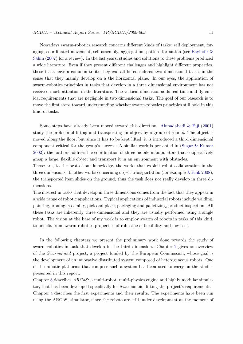
Nowadays swarm-robotics research concerns different kinds of tasks: self deployment, for-aging, coordinated movement, self-assembly, aggregation, pattern formation (see Bayindir &Sahin (2007) for a review). In the last years, studies and solutions to these problems produceda wide literature. Even if they present different challenges and highlight different properties,these tasks have a common trait: they can all be considered two dimensional tasks, in thesense that they mainly develop on a the horizontal plane. In our eyes, the application ofswarm-robotics principles in tasks that develop in a three dimensional environment has notreceived much attention in the literature. The vertical dimension adds real time and dynam-ical requirements that are negligible in two dimensional tasks. The goal of our research is tomove the first steps toward understanding whether swarm-robotics principles still hold in thiskind of tasks.
Some steps have already been moved toward this direction. Ahmadabadi & Eiji (2001)study the problem of lifting and transporting an object by a group of robots. The object ismoved along the floor, but since it has to be kept lifted, it is introduced a third dimensionalcomponent critical for the group’s success. A similar work is presented in (Sugar & Kumar2002): the authors address the coordination of three mobile manipulators that cooperativelygrasp a large, flexible object and transport it in an environment with obstacles.Those are, to the best of our knowledge, the works that exploit robot collaboration in thethree dimensions. In other works concerning object transportation (for example J. Fink 2008),the transported item slides on the ground, thus the task does not really develop in three di-mensions.The interest in tasks that develop in three dimensions comes from the fact that they appear ina wide range of robotic applications. Typical applications of industrial robots include welding,painting, ironing, assembly, pick and place, packaging and palletizing, product inspection. Allthese tasks are inherently three dimensional and they are usually performed using a singlerobot. The vision at the base of my work is to employ swarm of robots in tasks of this kind,to benefit from swarm-robotics properties of robustness, flexibility and low cost.
In the following chapters we present the preliminary work done towards the study ofswarm-robotics in task that develop in the third dimension. Chapter 2 gives an overviewof the Swarmanoid project, a project funded by the European Commission, whose goal isthe development of an innovative distributed system composed of heterogeneous robots. Oneof the robotic platforms that compose such a system has been used to carry on the studiespresented in this report.Chapter 3 describes ARGoS : a multi-robot, multi-physics engine and highly modular simula-tor, that has been developed specifically for Swarmanoid fitting the project’s requirements.Chapter 4 describes the first experiments and their results. The experiments have been runusing the ARGoS simulator, since the robots are still under development at the moment of

12 IRIDIA – Technical Report Series: TR/IRIDIA/2009-009
writing this document. Nevertheless, the simulator is designed to allow a seamless transfer ofthe controllers to the real robots.Chapter 5 describes the work that is currently being carried out.Finally chapter 6 summarizes the main achievements of the work presented here, and outlinesfuture directions of the research.
Chapter 2
Swarmanoid
The research work presented in this dissertation has been carried out in the context of theSwarmanoid project. Swarmanoid is a Future and Emerging Technologies (FET-OPEN)1
project funded by the European Commission. The project, following and extending theSwarm-bots project (see Dorigo et al. (2005), Mondada et al. (2004) for a review), involves fiveEuropean partners: CNR-ITSC (Consiglio Nazionale delle Ricerche, Roma, Italy), EPFL-LIS(Laboratory of Intelligent Systems, Ecole Polytechnique Federale de Lausanne, Switzerland),EPFL-LSRO (Institut de Production et Robotique - Laboratoire de systemes robotiques,Ecole Polytechnique Federale de Lausanne, Switzerland), IDSIA (Istituto Dalle Molle di Studisull’Intelligenza Artificiale, Lugano, Switzerland), IRIDIA-CoDE (ULB, Bruxelles).
The scientific goal of the Swarmanoid project is to propose a new way of designing roboticsystems that can live along with humans in human modified environments, performing gen-eral purpose tasks. The project goal is pursued through the design, implementation, andcontrol of a novel distributed robotic system. The system will be made up of heterogeneous,dynamically connected, small autonomous robots. The organization of these heterogeneousrobots in a swarm, yields to a “super entity” called Swarmanoid, which gives the name to theproject. Swarm-robotics approach has been chosen because of its scalability, flexibility, androbustness properties.
Besides the development of the hardware platforms, Swarmanoid aims at studying newcontrol methodologies for the three types of robots. In the traditional methodology, first acontroller for a single robot is developed, then swarm behavior with similar robots is inserted,and then finally interaction with the other types of robots is added. We will avoid as muchas possible this approach, favoring the opposite one. Since one of main points of interestof the project is the heterogeneity among robots, controllers for the three families of robotsare developed in parallel, so that the possible cooperative issues are tackled and solved in
1http://cordis.europa.eu/ist/fet/home.html
13

14 IRIDIA – Technical Report Series: TR/IRIDIA/2009-009
a smoother and more natural way. Furthermore, many interesting control issues are worthstudying, such as the coordination of individual local perception by the robots into a coherentrepresentation of the environment, and the study of mechanisms for adaptive task allocationin heterogeneous teams.
Another source of innovative challenges, which have never been addressed before, involvesthe study of communication in an heterogeneous swarm of robots. For instance, the emergenceof communication in a robotic system in which hardware differences plays a central role is acompletely new question. Finally, also studying explicitly how to efficiently share informationamong robots with so strongly different capabilities is a novel issue considered in Swarmanoid.
To operate on human-oriented tasks we can identify three main capabilities a robotic sys-tem must have: vision, manipulation, and locomotion. The “standard” robotics approach tothis problem would make use of a complex robotic platform which embeds all those capabil-ities. In Swarmanoid, the system is composed of a swarm of heterogeneous robots of threekinds, each providing one of the mentioned capabilities. The robots interact with each otherto share abilities and complete their tasks. The three kind of robots, composing the swarmsare: foot-bot, eye-bot, and hand-bot. The following three sections describe each of the robots.Since the hand-bot plays a central role in our research, it is described at a higher level ofdetail than foot-bot and eye-bot.
2.1 Foot-bot hardware
The foot-bots (Fig. 2.1) are ground robots, whose design is based on the s-bot, the roboticplatform of the Swarm-bots project. Their basic capabilities are the same as in the s-bot : theycan move on the ground through a powerful treel drive and they can connect to objects usinga gripper2. Despite having the same functionalities of the s-bot, the foot-bot represents a hugestep forward with respect to its ancestor. The treels motors are more powerful, allowing therobots to pull more weight. Hot swappable, long-lasting, lithium polymer batteries do notrequire to stop the robot and connect it to a recharging device, as with the s-bot. A supercapacitor keeps the robot alive while the battery is swapped, allowing for virtually limitlessexperiments. The camera has been upgraded to 2.0 mega-pixels UXGA technology, withon-board image pre-processing. A rotating long-range3 infrared scanner allows perception ofobjects form a long range.
The role of the foot-bot in the project is, as the name suggests, to provide the locomotiveability to the heterogeneous swarm. They can, in fact, dock to the hand-bot to transport it to
2This is possible only for some geometries3Up to 1.5 m.
IRIDIA – Technical Report Series: TR/IRIDIA/2009-009 15
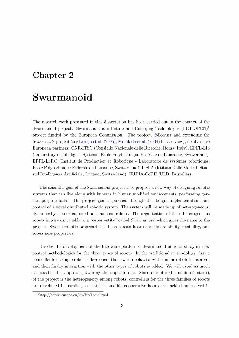
Figure 2.1: CAD model of the robot foot-bot.
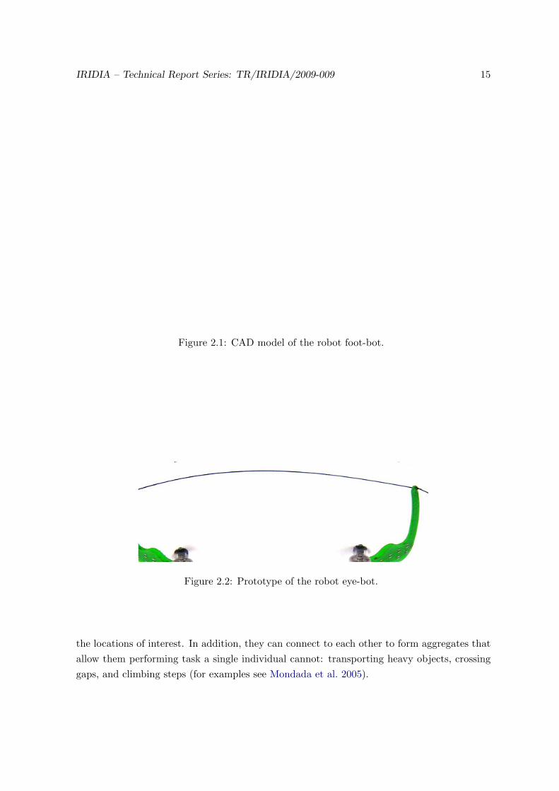
Figure 2.2: Prototype of the robot eye-bot.
the locations of interest. In addition, they can connect to each other to form aggregates thatallow them performing task a single individual cannot: transporting heavy objects, crossinggaps, and climbing steps (for examples see Mondada et al. 2005).

16 IRIDIA – Technical Report Series: TR/IRIDIA/2009-009
2.2 Eye-bot hardware
The eye-bots are autonomous flying robots with powerful sensing and communication abil-ities. This robot has undergone a series of prototyping steps: Figure 2.2 shows one of themost advanced prototypes (the quadrotor model). A robot of this type entails challenginghardware requirements. The very first constrain in on the weight: an heavier robot requiresmore energy consumption in order to make it fly. To allow the battery to last for a sufficientamount of time the design of the robot aimed at reducing the weight. An additional require-ment is on the payload: the more the robot can lift, the richer the set of sensors can be. Theactual prototype weights 400 g and can fly for 24 minutes with no payload or 15 minutes witha 116 g payload.
The eye-bot has also the ability to attach to a ferromagnetic ceiling by using a magnet.This capability can be used to save energy: if needed, the robot can decide to attach to theceiling and stop its motors. From this privileged position, the robot can still monitor theenvironment and communicate with the others, but it it not consuming much energy.
The robot is equipped with Proportional-Integral-Derivative (PID) stability controllersthat run at 500 Hz, whose goal is to stabilize the platform during flight. Those low levelcontrollers can keep the robot flying in a certain position. However, due to the inaccuraciesin sensors and the dynamic environment the eye-bot will slowly drift in a random directionif it is not provided with position correction information. An optic-flow sensor, is under de-velopment in order to tackle this problem.
The eye-bot is equipped with a 2.0 mega pixel CMOS colour camera which resolution isadjustable through software using thus allowing for a digital zoom functionality. The camerais capable of panning 360◦ in the horizontal plane and tilting 90◦ from vertical to horizontal.This allows the visual scanning of the environment underneath the robot. The same pan andtilt system is equipped with a laser pointer, which can be used to focus attention of otherrobots on some specific locations.
The role of the eye-bot in the project is to provide vision to the heterogeneous swarm,guide the other robots toward target zones, and supervise the operations. The idea is thatthe swarm of eye-bots has to explore the environment, by spreading around and forming achain. Then, by using their sophisticate and flexible vision system, they can scan a roomsearching for objects of interest. Finally they can communicate to the other robots, in orderto guide them along the chain and get to the object.

IRIDIA – Technical Report Series: TR/IRIDIA/2009-009 17
Figure 2.3: CAD model of the robot hand-bot.
2.3 Hand-bot hardware
The hand-bot is probably the most challenging hardware platform, in terms of design andimplementation, among the robots that compose the Swarmanoid. In fact, this robot has tobe able to climb structures, such as shelves, and at the same time being capable of graspingobjects.Autonomous climbing is a complex task, to which different solutions are being applied (seefor example (Murphy et al. 2009)). The requirements of the hand-bot are severe, because thesame platform used for climbing has to be capable of grasping objects. Once developed, thehand-bot will be a unique piece of engineering, with no other robotic platforms with similarcharacteristics.
In the context of Swarmanoid, the hand-bot role is to retrieve objects located on shelves.The idea is that foot-bot connect to the hand-bot and take it at the bottom of a shelf (asthe hand-bot cannot move alone). Once there, the hand-bot is supposed to climb the shelf tosearch for an object to be retrieved.
The hand-bot has been chosen as the tool to carry out our research in cooperative robotics.The motivation behind this choice comes from the main characteristics of the robot:

18 IRIDIA – Technical Report Series: TR/IRIDIA/2009-009
1. as part of a swarm, the robot’s capabilities are kept as simple as possible, this is in ac-cordance with swarm-intelligence philosophy, that demands interaction of simple agents;
2. it has the capabilities to move and perform meaningful actions in a vertical direction,adding a three dimensional component in its tasks;
Thus, combining the two properties allows to study to which extent cooperation can be ex-ploited as a way of overcoming individual limitations in task that require acting in a threedimensional space.
The control architecture of the hand-bot is shares a set of basic subsystems, common toall robots. Having the same control architecture for all the robots facilitates the hardwaredevelopment and provides researchers with a coherent tool set to build their controllers upon.The common set of capabilities comprises the following:
• the main processor board: the Freescale i.MX31 arm 11 processor, a low-energy 533 MHzprocessor with a complete collection of subsystems such as usb host controller and in-tegrated camera interface;
• the main core board built around the processor which provides 128 MB of ddr ram
and 32 MB of flash;
• a set of DsPIC 33 micro controllers for sensors and actuators;
• wireless communication in two fashions: WiFi, mainly intended for (relatively) longrange inter-robot communication, and Bluetooth, for basic robot setup and short rangeinter-robot communication.
Concerning the actuators set of the robot, one of the main actuators of the hand-bot is therope launcher(see Fig. 2.4 on the right), that is used to shoot a rope, ending with a magnet.
The purpose of this actuator is to allow the hand-bot to attach with a rope to the ceiling.This capability is mainly used to assist the robot during climbing: the hand-bot climbs theshelves by attaching to them with its arms, but when performing this operation, it needs therope in order to sustain the body weight and to assist the climbing process.
The magnetic attach requires the ceiling to be ferromagnetic. This is a limitation in theenvironmental setup the has been introduced in order to simplify the development and thehardware requirements of the robot. This is an acceptable hypothesis, considering that thereare several studies which concern technologies that can make the attach mechanism indepen-dent from the target (see for example (Murphy et al. 2009)).

IRIDIA – Technical Report Series: TR/IRIDIA/2009-009 19
Figure 2.4: CAD model of the rope launcher, used by the hand-bot to shoot the rope andattach to magnetic ceilings. Left: rope launcher sectioned vertically. Right: external part ofthe rope launcher, including the cable rolling wheel.
The launcher works as follows: a strong motor loads the magnet by shrinking a spring(see Fig. 2.4 left). When the spring is freed, it shoots the magnet vertically and, at the sametime, a fast motor unrolls the cable to follow the raising magnet. If a ferromagnetic objectis on the way, the magnet attaches. At that point the robot can go up and down rolling andunrolling the rope, controlled by a strong motor. The magnet is detached by a mechanismthat turns it by 90◦, so that the magnetic field becomes weaker with respect to the ceiling,and the magnet can be pulled out. When the magnet is detached, the cable is rolled back bythe fast motor to prevent the magnet from hitting objects while falling.
An encoder allows to measure the length of the rope that is currently unrolled, this infor-mation can be used for precise4 height regulation.Traction on the rope is measured through a torque sensor which monitors the torque on themotor that rolls and unrolls the cable. This information can be used to avoid dangerousoverloads on the robot when trying to lift objects or, for example, to deduce the weight ofan object being lifted. While hanging, the orientation of the hand-bot’s body along the threeaxis can be monitored by using a gyroscope.
As mentioned earlier, the hand-bot needs to be transported by the foot-bots in order toreach the positions of interest. To allow this to happen, the hand-bot is equipped with a ring(see Fig. 2.5 left) that allow the connections to take place. The foot-bot is equipped with agripper (see Fig. 2.5 right) that, when opened, fits the shape of the ring and joins the tworobots. The very same ring is present on the foot-bot, to allow them to assemble with eachother and form bigger structures.
4The error is estimated to be of the order of 1 mm

20 IRIDIA – Technical Report Series: TR/IRIDIA/2009-009
Figure 2.5: LED ring and gripper. Left: LED ring lightened up in different colors. The LEDring is used for communication and robot detection through cameras. It also serves as dockingmechanism to allow robot assembly. Right: CAD model of the foot-bot gripper. The grippercan open and fit the LED ring shape, providing a connection point between different robots.
Along the ring there are 12 LEDs (8 on the foot-bot), each of which can be lightened up in-dependently from the others. The LEDs can be used to make it easier to perceive the robotsby using cameras, as well as to communicate visually with the other robots (see as examples(Nouyan et al. 2008, Christensen et al. 2007)).
Besides climbing on objects and assembling with foot-bots, the hand-bot has powerful ma-nipulation capabilities. Two strong arms, each with 4 rotational degrees of freedom, providethe flexibility needed to grasp objects. The two arms can rotate with respect to the body, asshown in Figure 2.6 (dashed arrows). The rotation of the arms is not independent: they areforced to be always aligned.
In addition, the arms can open and close, along the direction shown by the continuousarrows of Figure 2.7. In this case, each arm can be moved independently from the other;during the movement the grippers keep always the same orientation, depicted in the figure.Concerning the grippers, they can be opened and closed, as shown in Figure 2.7 (continuousarrows), and they can rotate as shown by the dashed arrows of Figure 2.6.
The arms are not only used to manipulate objects, but they also assist the hand-botduring climbing. In fact, while hanging from the rope, the hand-bot is not very stable asit oscillates and spins. Grasping an object on a shelf requires the body to be as stable aspossible, as well as the arms to lean out towards the shelf. The robot can use its harms tograb the shelf while climbing, which maintains the body stable while going up.

IRIDIA – Technical Report Series: TR/IRIDIA/2009-009 21
Figure 2.6: Front view of the hand-bot. The arms can rotate with respect to the body (seedashed arrows) and the grippers can rotate with respect to the arms (see continuous arrows).
Each motor inside the arms is equipped with encoders to measure the angular positions ofthe parts with a 0.1◦ precision. Through the encoders it is possible to measure: the currentorientation of the arms with respect to the body, the aperture of each arm, the orientationof each gripper with respect to the arm, and the aperture of each gripper. These informationcan be used, if combined with the geometry of the robot, to compute the Cartesian positionsof each part with respect to the body.
Each gripper is provided with a set of twelve infrared proximity sensors (see Fig. 2.8). Theinfrared sensors are intended to be used as “tactile” system for the robot: the informationcoming from these sensors can be used by the hand-bot to perceive the position of the objectsto be grasped, as well as to align to the shelves part while climbing.
The set of sensors is completed by three fish-eye 2 MegaPixels cameras with on-boardimage pre-processing (such has edge detection routines). The cameras are placed one insideeach gripper and one in front of the robot, between the two arms. They are intended to

22 IRIDIA – Technical Report Series: TR/IRIDIA/2009-009
Figure 2.7: Top view of the hand-bot. The arms can open and close along the path of thecontinuous arrow, the grippers can open and close along the path of the dashed arrows.
provide the robot with a vision system which allows objects detection and recognition andvisual communication with other robots through LED signalling.
In addition, the hand-bot and the other robots might be equipped with a fully threedimensional range and bearing system. This would give the robots an additional communi-cation channel, usable to send simple messages in a limited range. Along with the message,the receiving mechanism allows to deduce the relative distance and orientation of the sender.The range and bearing system has been prototyped, but given its complexity and the smallknowledge in this field, its presence on the real robots is not assured. Adding such a systemwould increase the potential experiments involving the different kinds of robot, since fully3 dimensional neighbour detection and communication would become possible and easy toimplement.

IRIDIA – Technical Report Series: TR/IRIDIA/2009-009 23
Figure 2.8: Depiction of IR proximity sensors inside the grippers. Those sensors help objectgrasping manoeuvres.

24 IRIDIA – Technical Report Series: TR/IRIDIA/2009-009

Chapter 3
ARGoS
In robotics, the use of simulation tools is essential for the development of controllers. Themain reason is that they allow testing controllers without the risk of damaging the hardware.Damages can occur either because the robots bump into objects or because the controlleroverloads the actuators. A simulation environment allows to prevent those situations to hap-pen before they actually happen on the physical robots.
Another characteristic that makes simulations convenient is the speed of execution. Infact, a software can simulate hours of real time in some minutes, removes all the down times(example: time to replace robots’ batteries or to set the environment up), and allows parallelexecution of the same experiment on different computers. Additionally, measures collectionand statistical analysis are usually easier in a simulated than in a real environment.
As additional benefit for swarm-robotics studies, a simulator allows to test algorithms andproof empirically their working principles with a huge amount of robots, which might not beavailable in reality.
On the downside, the intrinsic complexity of a (multi-)robot system and of the real-worldenvironment, makes sometimes hard the design of realistic simulation models to derive soundevaluations and predictions of the robotic system under study. In other words, the fact that arobot controller shows a given behavior in simulation does not mean that the same controlleron the real robot will perform the same way. This comes from the fact that a behavior arisesfrom the interaction between the robot and its environment, and the simulated environment isdifferent with respect to the real one. Adding noise to the simulations (e.g. to sensor readingsand actuators outputs) helps bridging the gap between simulation and reality (Jacobi 1997).
The simulator developed for the Swarmanoid project is called ARGoS 1. ARGoS is a custom
1acronym for Autonomous Robots Go Swarming
25

26 IRIDIA – Technical Report Series: TR/IRIDIA/2009-009
Physics Engines
Common Interface
Visualizations
Specific
Generic
Generic
Specific
Robot Controller
Sensors
Swarmanoid Space
2D Kinematics 2D Dynamics 3D Dynamics
Actuators Text
OpenGL
OGRE
Figure 3.1: Overall architecture of the simulator.
software, written in C++ language, which implementation relies on free and open-source re-sources.
Despite the availability of several simulation software for robotics studies, the decision ofwriting a new simulator from the scratch was taken. The main reason is the fact that Swar-manoid proposes a novel set of robots, two of which (eye-bot and hand-bot ) have peculiaritiesthat exist only in the context of the project. Thus, in order to simulate the specific charac-teristics of the robots composing the Swarmanoid by using an existing simulator platform,we would have needed in any case to implement from scratch the majority of the modules.For instance, none of the currently available simulators include modules that could help tosimulate the hand-bot climbing along the vertical dimension by shooting a rope that getsmagnetically attached to the ceiling.
Therefore, in the case of choosing to adapt an existing simulator to our needs, we wouldhave found ourselves in the position of implementing from scratch, and/or heavily adapting,most of the simulation modules. This choice would have vanished the benefits of using apreexisting simulator, and at the same time forced us to adapt to a general software structureselected by a third party.
The conceptual architecture of ARGoS is shown in Figure 3.1. The simulator architectureis organized around one single component, the Swarmanoid Space. This is a central reference

IRIDIA – Technical Report Series: TR/IRIDIA/2009-009 27
system representing the state of the simulation at each simulation step. It contains informa-tion about the position and orientation of each of the simulated entities: robots and all otherobjects that are present in the simulated environment.
The other components of the simulator interact mainly with the Swarmanoid Space.Physics engines calculate physical movements and interactions based on the actions of thedifferent simulated entities; they then update the Swarmanoid Space with the new state ofthe simulated system. Renderers allow the visualization of the content of the SwarmanoidSpace at each simulation step. Sensors and actuators can interact either with the SwarmanoidSpace or directly with the physics engines.
This architecture, with the Swarmanoid Space as central reference point, has been thoughtto give high modularity to the software: each of the sensors, actuators, renders and physicsengines are implemented as plug-ins and can be easily changed, selected and tuned throughan XML configuration file.
Another core feature of the simulator is the Common Interface. This is a collection of in-terfaces that defines the functions that are available to a robot controller for interacting withsensors and actuators. The common interface will be the same on the real robots as it is inARGoS . This has been done to allow having the same controller code working in ARGoS andon the real robots. The controller, in fact, ignores whether it is interacting with simulatedsensors and actuators or real ones. This will speed up the development of the controllerswhen the robots will be available. All the experiments presented in this report (see Chapter4) have been conducted using the ARGoS simulator.
The rest of this chapter describes the work done for the implementation of the hand-botmodel inside the simulator.
3.1 ODE model
Currently the hand-bot is modelled and available in the 3D dynamics physics engine. Despitethe fact that several physics engines are available in ARGoS , the robot’s characteristics androle makes it natural to have an implementation in a fully three dimensional world.The 3D dynamics physics engine is based on ODE (Smith 2001), which is an open sourcelibrary for simulating rigid bodies dynamics. For a comparative study involving some of thephysics engines currently available, including ODE, see Seugling & Rolin (2006).
ODE allows the user to create bodies and compose them through joints, while the librarytakes care of simulating the interactions of these bodies. Bodies are ODE primitives that
28 IRIDIA – Technical Report Series: TR/IRIDIA/2009-009
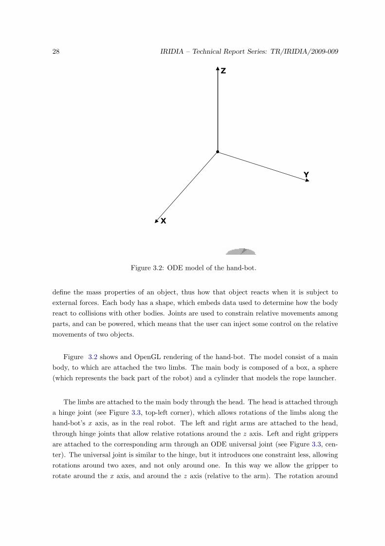
Figure 3.2: ODE model of the hand-bot.
define the mass properties of an object, thus how that object reacts when it is subject toexternal forces. Each body has a shape, which embeds data used to determine how the bodyreact to collisions with other bodies. Joints are used to constrain relative movements amongparts, and can be powered, which means that the user can inject some control on the relativemovements of two objects.
Figure 3.2 shows and OpenGL rendering of the hand-bot. The model consist of a mainbody, to which are attached the two limbs. The main body is composed of a box, a sphere(which represents the back part of the robot) and a cylinder that models the rope launcher.
The limbs are attached to the main body through the head. The head is attached througha hinge joint (see Figure 3.3, top-left corner), which allows rotations of the limbs along thehand-bot’s x axis, as in the real robot. The left and right arms are attached to the head,through hinge joints that allow relative rotations around the z axis. Left and right grippersare attached to the corresponding arm through an ODE universal joint (see Figure 3.3, cen-ter). The universal joint is similar to the hinge, but it introduces one constraint less, allowingrotations around two axes, and not only around one. In this way we allow the gripper torotate around the x axis, and around the z axis (relative to the arm). The rotation around

IRIDIA – Technical Report Series: TR/IRIDIA/2009-009 29
Figure 3.3: ODE joints, used to connect the hand-bot parts. Top-left: hinge joint, allowsrelative rotations of two bodies along a common axis. Top-right: slider joint, allows relativetranslation of two bodies along a common axis. Bottom-left: universal joint, allows relativerotations of two bodies along two axes. Bottom-right: ball joint, allows relative rotations oftwo bodies around the anchor point.
the x axis can be controlled, allowing thus to set the orientation of each gripper, as in thereal hand-bot. The rotation around the other axis is not directly controllable, it is used tofollow the arm rotations and keep the gripper facing in a forward direction, as it happenswith the real robot: the grippers are forced to be always pointing towards the same direction,whatever the arm position is (see 2.3).
Finally the four claws are attached to the grippers through hinge joints, that allow relativerotations along the z axis. All the joints are powered through an ODE “amotor” (angularmotor), which allows the user to control the relative rotations between two bodies. Thus, thejoint constrain the movements of the bodies, while the amotor is used to control the motion.Through the joints it is possible to set limits on the relative rotations between parts, as hap-pens on the real hand-bot (e.g. the arms max aperture is 90◦). The angular motor allows todefine control parameters such as maximum speed and torque of the motor.
The following two sections explain in detail the work done to implement the actuatorsand the sensors of the hand-bot.
30 IRIDIA – Technical Report Series: TR/IRIDIA/2009-009
3.2 Implemented actuators
The set of actuators of the hand-bot is composed of LEDs, limbs motors, and the ropelauncher. The implementation of the motors controlling the movements of the limbs wasstraightforward, given the fact that ODE allows motion control, by acting on the joints (seeprevious section). Noise has been added in order to match the precision of the encoders ofthe real hand-bot2.
To model the hand-bot’s ability in grasping objects, we implemented three kinds of actu-ators for the gripper. The first model makes use of ODE friction. When two objects collide,ODE creates temporary joints, called “contact joints” between them3. These joints are usedto apply instantaneous forces to the two colliding bodies, which allow to simulate bouncingand friction properties of different materials. By closing the gripper around an object is pos-sible, through friction, to grab that object, exactly as it would happen in the real world.
A second model of the grippers makes use of ray-cast and ODE joints. When the gripperis being closed and the gripper aperture goes below a certain limit, two rays, parallel to thegripper’s claws, are checked for intersections with the objects in the simulated world. If bothrays intersect the same object, then the object is considered to be gripped: a ball joint as theone in Figure 3.3 (bottom-right) is then created on the fly to attach the gripper to the object.When the gripper is opened the joint is destroyed and the object dropped. This model is lessrealistic but it has an advantage: the gripped object cannot be dropped unless the gripper isopened and the ball joint destroyed.
The third model, called magic gripper, is even more simple: when the gripper is closed,the closest object inside a certain distance range, is physically moved inside the gripper, anda ball and socket joint is created to attach the object to the gripper.
We decided to implement three different mechanisms to allow choosing between differentlevels of approximation. If the experimenter wants to concentrate on the grasping manoeuvreand wants to simulated the fact that the object can fall, then the model based on ODE frictionshould be used. If the grasping procedure is important, but there’s no interest in simulatingthe fact that abn object can fall from the gripper, then the model based on ray-cast is agood candidate. Finally the magic gripper should be used when there is no interest at all insimulating the whole grasping procedure, but only the fact that the robot gets close to thetarget and grasps it, in order to perform some subsequent action.
2The motor encoders will be very precise, with an error of the order of 0.1◦ on the final position of the limb3Temporary because they are destroyed after each time step

IRIDIA – Technical Report Series: TR/IRIDIA/2009-009 31
Figure 3.4: Schematic view of the hand-bot rope, implemented using ODE. The rope isimplemented as a slider joint, that allows to control the translation of hand-bot’s body. Theball and socket joint attached to the ceiling allows swings, the other ball and socket jointallows the robot’s body to rotate with respect to the rope.
Concerning the LEDs, their implementation is very simple: each LED has a position,relative to the robot’s body, and its color can be set through the controller. The LEDs canthen be seen by the cameras: at each time step the cameras on the robot query each entityto ask where the LEDs are positioned and which is their actual color.
The biggest amount of work was required to implement the rope and the launching mech-anism. The problem with the implementation of the rope resides in the fact that ODE isdesigned to simulate rigid bodies dynamics, while the rope is a flexible object. To keep theimplementation easy we made an assumption: we modelled the rope as a rigid bar with nomass. This is a reasonable approximation of what will be the real system: the mass of therobot4 is orders of magnitude bigger than the one of the rope. This means that when thehand-bot is hanging from the ceiling, the rope will always be in tension, and can therefore beapproximated as a rigid bar. When the robot is attached to the ceiling, it can perform twokinds of movements:
1. it can swing as a pendulum around a pivot point on the ceiling;
2. its body can rotate around the contact point between the rope and the launcher;
Implementing these behaviors using ODE primitives (joints and bodies) required to build themodel depicted in Figure 3.4.The rope is built using two bodies (grey squares labelled with “A” and “B” in Fig. 3.4)connected to each other trough a slider joint (see Figure 3.3 top-right). These two bodies
4The mass will be around 2 Kg

32 IRIDIA – Technical Report Series: TR/IRIDIA/2009-009
are needed because ODE allows to attach joints only to bodies and not among themselves,thus the bodies are used only as “glue” points between the joins composing the rope. Oneof the two bodies (“A”) is attached to the ceiling by a ball and socket joint (see Figure 3.3bottom-right), the other body (“B”) is attached to the hand-bot’s rope launcher by a balland socket joint. The ball and socket joints allow the two bodies they connect to freely rotatein any direction with respect to each other, but they constrain translation by keeping the twoobject stick together. The slider joint allows the relative translation of the two bodies “A”and “B” along the slider axis. Consequently, the slider joint is used to model the ability ofthe hand-bot of climbing: by setting a force on the slider, the bodies “A” and “B” are pulledone towards the other. Since “A” is constrained by the ball and socket joint to be fixed tothe ceiling, and the ceiling does not move, the effect is that the body “B” will move towardsthe ceiling. When “B” moves, the launcher and the rest of the robot moves with it since itis constrained by the other ball and socket joint. The ball and socket joints give the othersdegrees of freedom to the system: the one attached to the ceiling allows the system to swingas a pendulum, the other allows pitch, roll and yaw movements. The slider joint used for therope is a modified version of the one supplied by ODE: the ODE slider can apply forces inboth direction, thus could have happened that, while descending, the robot body was pushedby the rope. This does not reflect the behavior of a real rope, thus we needed to extend ODEwith a slightly modified version of the slider joint 5, which is able to apply forces only to pull,but not to push the bodies.
Notice that the rope is built only when needed. In case the rope needs to be shot, first acheck is done to see whether and object is on the trajectory of the rope (through ray-cast).In case the rope hits the ceiling, the system depicted in Figure 3.4 is created on the fly. Somenoise has been added to the system: there is a 2% probability of failure in shooting the rope,which models cases in which the rope is shot, but it fails to attach; in addition the rope isnot shot perfectly vertical, but there is always a small, random, inclination (sampled froma Gaussian distribution). Once the hand-bot hardware will be available, tests are needed inorder to characterize the noise parameters to reflect the real behavior.
As final remark concerning the rope model: there is a situation in which the model doesnot reflect the real rope behavior. This situation happens when the rope hits some obstacles.In the real world, this would cause the rope to bend and the robot body to oscillate or vibratein some way. In our simulation, the rope is a joint, it does not have any physical propertybeside the ability to act on the bodies it is connecting. This means that our rope cannot hitany object, for example an eye-bot could fly through it. In our eyes this is not a big issue,since situations in which an object hit the rope has to be avoided in real experiments (theywould damage the robots), thus we do not need accurate modeling of these situations.
5We called it “rope joint”
IRIDIA – Technical Report Series: TR/IRIDIA/2009-009 33
The following section describes the work done to implement all the sensors for the hand-botmodel.
3.3 Implemented sensors
The hand-bot is equipped with a rich set of sensors: cameras, infrared proximity sensors,encoders, torque and traction sensors, gyroscopic sensor (see Section 2.3 for details). Con-cerning the encoder and the torque sensors, the implementation was quite straightforward,since they give measures associated to the motors, and ODE gives access to this informationthrough values on the joints. In the same way the gyroscope is implemented by querying theODE engine for the orientation of the hand-bot’s body. Random Gaussian noise was addedto all the readings. Apart the encoders, whose maximum error is known to be of the order of0.1◦, the noise model of the others sensors needs to be derived through tests, once the robotwill be available.
The infrared proximity sensors, placed in the grippers, are currently implemented throughray-cast: each sensor is modelled as a ray. At each time step, the sensor readings are updatedby checking whether the ray intersect an object at a distance closer than a certain range(fixed at 50 cm as first approximation). If the ray hits an object, the corresponding sensorgives directly as reading the distance to that object. Notice that the real infrared proximitysensors have a cone-like shape as the one in Figure 2.8. Nevertheless, it is a common practiceto implement the infrared proximity sensors through ray-cast and then add noise to have abehavior that is closer to the real one. The actual implementation gives directly the distanceof the object hit by the ray, this is a temporary solution we adopted while waiting for thehardware to be available. The real sensor will, in any case, give readings that are proportionalto the distance, the mapping between distance and reading will derived by making tests withthe robot.
An alternative implementation to this model is based on lookup-tables: the sensors read-ings of the real robot are sampled for a set of distances and ranges with respect to targetobjects, and a table is built. This table is then used in simulation: when a potential targetis in the sensors’ range, its distance and orientation with respect to the robot are computed.The table is searched for the situation that closely matches the distance-orientation pair andthe sampled readings are given, with the addition of some noise. This model will be imple-mented as soon as sensors’ samples will be available.The situation of the three fish eye cameras (see 2.3) is similar, in the sense that withoutthe real robot, it is hard to implement a model. In this case the situation is even worse,since the proximity sensors qualitative behavior is well known. The camera is different, sinceit has on-board image pre-processing, which nature is still not known: there will be color

34 IRIDIA – Technical Report Series: TR/IRIDIA/2009-009
Figure 3.5: Schematic view of the hand-bot’s camera. F is the center of the camera, L is aLED. The camera points along the intersection of the vertical and horizontal planes. Thecamera allows to measure the angles that the line going from F to L forms with respect tothe horizontal plane (α) and the vertical one(β), and the color of the LED.
segmentation and edge detection routines, but the kind of information that can be obtainedfrom the cameras is not known at the moment of writing. Despite this problems, the cameraconstitute the main perception mechanism that can be used by the robot, thus we decided toimplement a simple model, to be used as a base to build more complex and realistic ones inthe future.
Figure 3.5 shows how the actual model of the cameras is implemented. The cameras canonly perceive LEDs (for example “L” in the figure); ray-cast is used to determine whether anobject is obstructing the view and hiding the LED. The information given by the cameras is,for each LED, the angles α and β, and the LED color. The angles are computed as follows:α is the angle between the line connecting the camera center “F” and the LED “L”, and thecamera’s horizontal plane. The angle β is between the same line and the vertical plane. Thecameras have a perception range of 3.0 m in distance, and and angular range of 90◦. Noise isadded to the measured angles, as well as to the distance and angular ranges.The model is very simple, but it represents the basic information that is expected to be avail-able through the camera. Higher level information coming from the pre-processing routineswill be added to the model once more information about the cameras will be available.
The set of sensors is completed by the range and bearing receiver, which can processmessages emitted by the other robots and deduce, with some error, the relative distance andheading of the emitter. As mentioned in Chapter 2.3 there is no warranty the system will bepresent on the robots, given the complexity of its realisation.

IRIDIA – Technical Report Series: TR/IRIDIA/2009-009 35
The next chapter describes the first experiments that have been conducted using thesimulator.

36 IRIDIA – Technical Report Series: TR/IRIDIA/2009-009

Chapter 4
Experiments
This chapter describes the experiments that have been conducted using ARGoS . The goalof the first experiment was the development of a grasping strategy, that allows the robot tograb box-shaped objects. Basic manipulation is required in order to implement more complexbehaviors, such as climbing on shelves or collective manipulation behaviors. Once a graspingroutine was developed, the following experiments aimed at exploring collective behaviors. Indetail, the second experiment involved two hand-bot lifting a bar, the third concerned thecollective exploration of a vertical surface. The following sections give details for each of theexperiment mentioned: their goal, the proposed solution and their results.
37

38 IRIDIA – Technical Report Series: TR/IRIDIA/2009-009
Figure 4.1: Initial setup for the object-grasping experiment. The robot and the board to begrasped are on the ground. The narrow side of the board is aligned with the hand to facilitatethe grasping. Left: back view. Center: top view. Right: front view.
4.1 Grasping simple objects
As mentioned, grasping an object is a basic capability that has to be implemented as buildingblock for more complex behaviors. The hand-bot is being built with the idea of a platformable to grasp objects and attaching to structures in order to climb them. Therefore, besidesthe goal of my personal research, implementing reliable grasping routines is a project-widerequirement.
The controller has been implemented having in mind the following assumptions (see also Fig.4.1):
1. Robot and board are placed on the ground;
2. The board is perfectly vertical;
3. The board is not too thin;
The first and second assumptions simplify the controller implementation. This configurationlooks quite limiting, but it is instead the most common the robot will face. In Swarmanoidthe swarms will have to collect book shaped objects. Therefore it is reasonable to assumethat those books will be positioned in the same way as the board in this experiment. Theonly difference is that the books will be placed on shelves, not on the ground. Since the goalof the experiment described here is to implement a grasping routine, the climbing phase isassumed to be finished. This means that the robot’s position with respect to the target objectwill be, with some approximation, as in Figure 4.1. As a consequence, in the configurationdescribed, the robot can eventually grasp the board by simply stretching its arm and closingthe gripper.The third hypothesis assures that the robot can hold the object in a safe way and perceive

IRIDIA – Technical Report Series: TR/IRIDIA/2009-009 39
Search
Go to pos
Angle found
End error
No object
Iterative Grasp
Arm positioned
Obj too far
Unsafe grip
End ok
Board grasped
Figure 4.2: Finite state machine representing the controller that allows the hand-bot to graspobjects.
its presence by means of the torque sensors on the gripper claws motors when the object isbeing grasped.
The controller is an implementation of the finite state machine depicted in Figure 4.2.Figure 4.3 shows the sequence of actions that occur in object grasping. Initially the controlleris in a “Search” state. In this state the robot stretches the arm (Fig. 4.3 A, B, C) to searchfor an arm angle which allows good grasping (the angle is measured using the encoders of thearm’s motor).
A good angle requires that the gripper of the hand-bot is close enough to the objectand with a sufficiently good alignment. During the search phase the robot uses the infraredproximity sensors to find such a position. While searching for a good position the controllercompares the readings against a threshold value and selects the arm position that allows fora good trade off between high sensor activation and good alignment. The search phase canend in two cases:
1. The arm is completely stretched;
2. Some infrared sensors are activated above a certain limit (risk of hitting the object);
Once the search phase ends, the controller eventually enter the “go to pos” state, in whichthe arm is positioned to the best angle found (if any, see Figure 4.3 D). When the arm reachesthe desired position, the grasping phase starts.Grasping the object is done in an iterative way: the robot closes its gripper ( Fig. 4.3 E)until the torque measured on the claws is above a threshold value. A high torque on theclaws means the object is actually gripped. The robot can hence check the activation of the
40 IRIDIA – Technical Report Series: TR/IRIDIA/2009-009
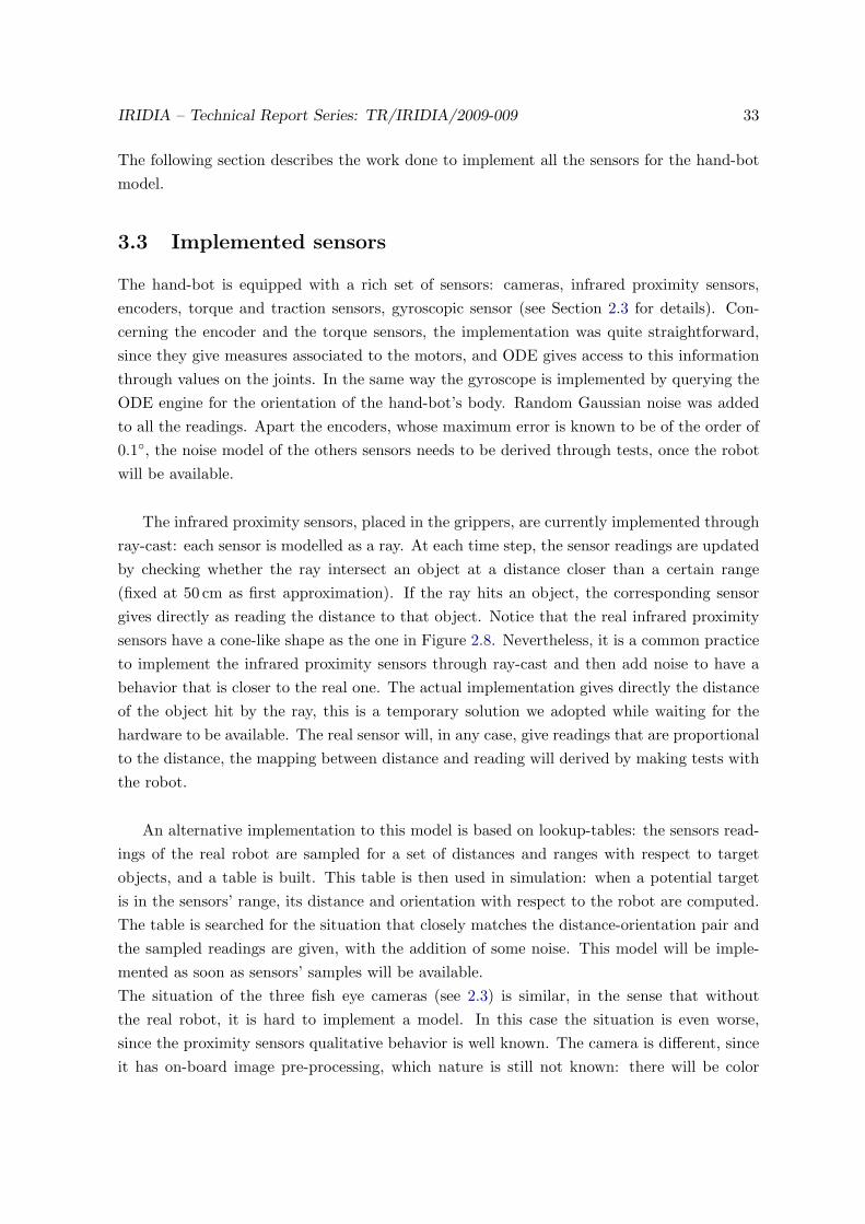
Figure 4.3: Sequence of movements to grasp the board. (A) Starting configuration. (B-C)The robot is searching for the arm angle that allows the best grasp. (D) The robot positionthe arm to the best angle found. (E-F) The robots closes the gripper to grasp the board. (G)The robot re-opens the gripper to correct the angle in case the grasp is not safe. (H-I) Therobot manages to successfully grasp the board.
infrared proximity sensors. If the sensors’ activation is too low (under a certain threshold) itmeans the object is being gripped with the tip of the claws, thus the grip is not safe. In thiscase the robot re-opens the gripper (Fig. 4.3 G), stretches a bit more the arm to get closerto the object and retries to grip (Fig. 4.3 H, I).
The controller has been tested in simulations using a board 20 cm tall, 10 cm long and4.5 cm wide. The board was placed in 4 different positions:
1. Too far to be grasped;
2. In grasping range, but too misaligned to allow a successful grasp;
3. In grasping range, very close to the hand once the arm was aligned;
4. In grasping range, far from the hand once the arm was aligned;

IRIDIA – Technical Report Series: TR/IRIDIA/2009-009 41
The four different configurations have all been tested, repeating the experiment 20 timeswith different initializations of the random numbers generator. In all the cases, the controllerrecognized the configurations 1 and 2 as object misplacing. This is a positive result, sinceit allows a higher level behavior to use the grasping routine and take corrective measures incase the target object is not reachable1.
In case 3, the controller has a success rate around 62%. The failures are due to the factthat the object can actually be grasped, but the controller sometimes considers the object asmisaligned and blocks the manoeuvre. Notice that this means that the actual experimentsends, but in case grasping is used as a sub-routine of a more complex behavior the situationcan bee tackled by correcting the robot’s alignment.
In case 4, the object is aligned and the controller is quite successful. The fact that theobject is far from the hand makes the controller to perform the iterative grasping procedure,described above. This could result in the object being pushed away and finish outside thearms’ range, thus the robot fails to grasp it.
Concluding, the goal of the experiment was to develop a strategy that allows the robot tograsp an object in the most common situation with relation to the Swarmanoid scenario. Wecan say that the grasping mechanism described here is fairly satisfactory. The procedure hasthe weak point that it can actually move the object during the iterative grasping. This canresult in pushing the object out of the robot’s range or, possibly, making it fall (this eventnever happened in our simulations). We think this is not a big issue, since the behavior canbe made more precise at the price of slowing it down.
As a final remark, object grasping is a low-level behavior, which requires strict interactionof sensors and actuators. The solution proposed here will need parameter tuning to betransferable on the real hardware. Nevertheless we believe the very same mechanism will beimplemented on the real hand-bot.
1Note that the controller can distinguish between the case in which the object is misalignment and the casein which is out of range
42 IRIDIA – Technical Report Series: TR/IRIDIA/2009-009
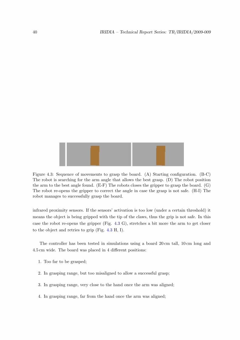
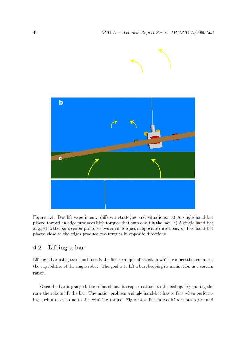
Figure 4.4: Bar lift experiment: different strategies and situations. a) A single hand-botplaced toward an edge produces high torques that sum and tilt the bar. b) A single hand-botaligned to the bar’s center produces two small torques in opposite directions. c) Two hand-botplaced close to the edges produce two torques in opposite directions.
4.2 Lifting a bar
Lifting a bar using two hand-bots is the first example of a task in which cooperation enhancesthe capabilities of the single robot. The goal is to lift a bar, keeping its inclination in a certainrange.
Once the bar is grasped, the robot shoots its rope to attach to the ceiling. By pulling therope the robots lift the bar. The major problem a single hand-bot has to face when perform-ing such a task is due to the resulting torque. Figure 4.4 illustrates different strategies and
IRIDIA – Technical Report Series: TR/IRIDIA/2009-009 43
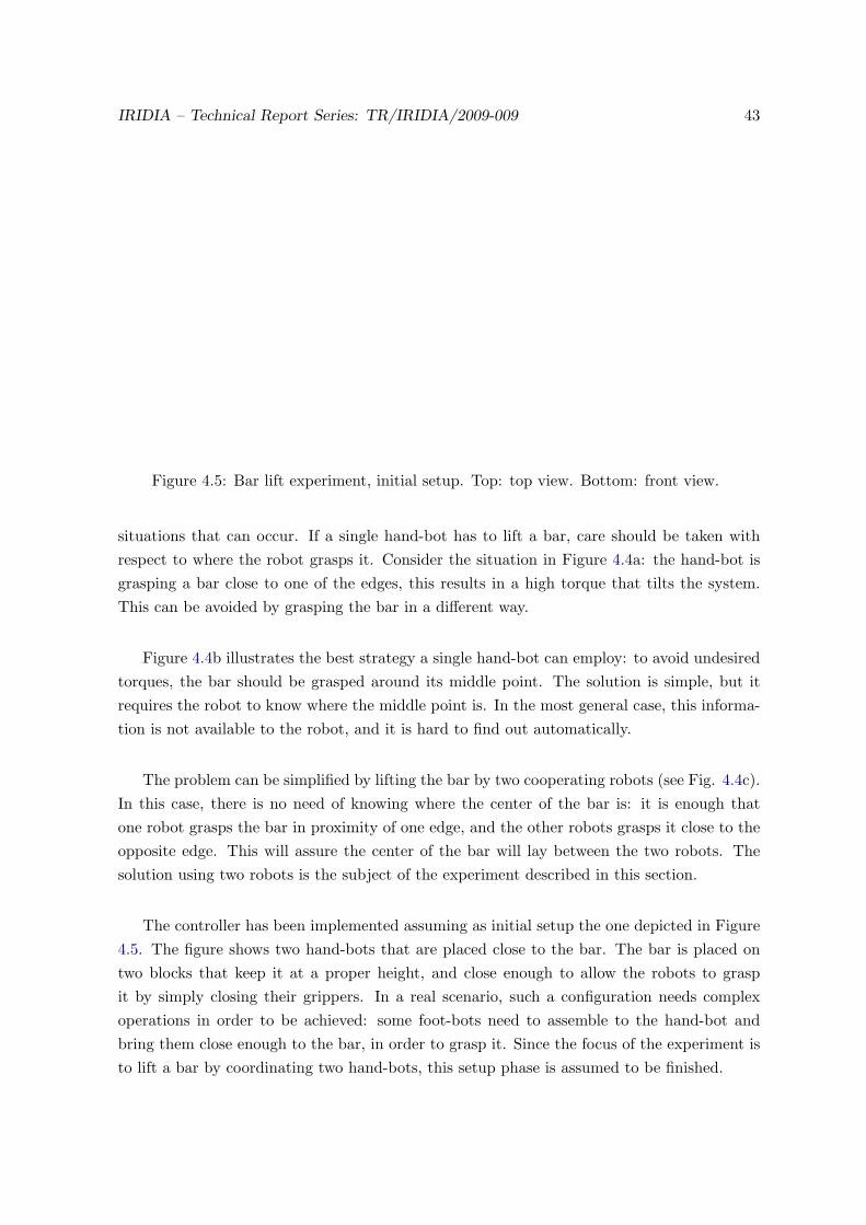
Figure 4.5: Bar lift experiment, initial setup. Top: top view. Bottom: front view.
situations that can occur. If a single hand-bot has to lift a bar, care should be taken withrespect to where the robot grasps it. Consider the situation in Figure 4.4a: the hand-bot isgrasping a bar close to one of the edges, this results in a high torque that tilts the system.This can be avoided by grasping the bar in a different way.
Figure 4.4b illustrates the best strategy a single hand-bot can employ: to avoid undesiredtorques, the bar should be grasped around its middle point. The solution is simple, but itrequires the robot to know where the middle point is. In the most general case, this informa-tion is not available to the robot, and it is hard to find out automatically.
The problem can be simplified by lifting the bar by two cooperating robots (see Fig. 4.4c).In this case, there is no need of knowing where the center of the bar is: it is enough thatone robot grasps the bar in proximity of one edge, and the other robots grasps it close to theopposite edge. This will assure the center of the bar will lay between the two robots. Thesolution using two robots is the subject of the experiment described in this section.
The controller has been implemented assuming as initial setup the one depicted in Figure4.5. The figure shows two hand-bots that are placed close to the bar. The bar is placed ontwo blocks that keep it at a proper height, and close enough to allow the robots to graspit by simply closing their grippers. In a real scenario, such a configuration needs complexoperations in order to be achieved: some foot-bots need to assemble to the hand-bot andbring them close enough to the bar, in order to grasp it. Since the focus of the experiment isto lift a bar by coordinating two hand-bots, this setup phase is assumed to be finished.

44 IRIDIA – Technical Report Series: TR/IRIDIA/2009-009
The controller is implemented as a PD (Proportional Derivative):
Rs(t) = Kp ∗ e(t) +Kd ∗de(t)dt
(4.1)
Where the control variable, Rs(t), is the rope speed at time t, Kp = 5.0 is the proportionalgain, Kd = 1.0 the derivative gain, and e(t) is the controlled variable (the bar inclination)2.The values of Kp and Kd have been determined experimentally by trial and error. The barinclination can be measured by using the gyroscope.Initially the controller makes the hand-bot to close its grippers and to shoot its rope. In thisway, the system is ready for the bar lifting procedure. After the rope has been shot and thebar has been grasped, at each control step each robot has 1% probability of start lifting thebar at a constant speed. This random component allows one of the two robots to break theinitial equilibrium and to activate the PD control. To keep the system going up once started,a
Once the controller was implemented, we compared the cooperative solution (Cooperativestrategy) against a single-robot approach (Single robot strategy). The experimental setup wasthe following:
• The bar length was set 4 m;
• The bar mass was set to 0.25 Kg when a single robot was lifting the bar, 0.5 Kg whentwo robots were employed;
• The robot was considered successful if it managed to lift the bar more than 10 m;
• The robot failed if the bar’s inclination exceeded 15◦;
The tests were run by changing the position of the robots relatively to the bar. In case tworobots were lifting, only one of the robot was moved, the other stayed in a fixed locationvery close to one of the bar’s edges. For each different setup, 10 randomly seeded runs wereexecuted.
The goal of the tests was to find, for each strategy, the success interval: the interval of posi-tions for the moving robot in which all the tests resulted successful (the robot(s) manage tolift the bar at least 10 m). Figure 4.6 summarizes the results of the tests.
2The terminology is taken from control theory. The controlled variables are the ones the controller monitors,in order to make them reach a determined value. The control variables are those the controller can affectdirectly, usually linked to some actuator
IRIDIA – Technical Report Series: TR/IRIDIA/2009-009 45
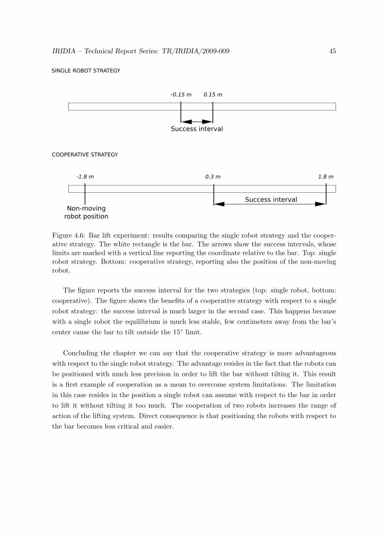
Figure 4.6: Bar lift experiment: results comparing the single robot strategy and the cooper-ative strategy. The white rectangle is the bar. The arrows show the success intervals, whoselimits are marked with a vertical line reporting the coordinate relative to the bar. Top: singlerobot strategy. Bottom: cooperative strategy, reporting also the position of the non-movingrobot.
The figure reports the success interval for the two strategies (top: single robot, bottom:cooperative). The figure shows the benefits of a cooperative strategy with respect to a singlerobot strategy: the success interval is much larger in the second case. This happens becausewith a single robot the equilibrium is much less stable, few centimeters away from the bar’scenter cause the bar to tilt outside the 15◦ limit.
Concluding the chapter we can say that the cooperative strategy is more advantageouswith respect to the single robot strategy. The advantage resides in the fact that the robots canbe positioned with much less precision in order to lift the bar without tilting it. This resultis a first example of cooperation as a mean to overcome system limitations. The limitationin this case resides in the position a single robot can assume with respect to the bar in orderto lift it without tilting it too much. The cooperation of two robots increases the range ofaction of the lifting system. Direct consequence is that positioning the robots with respect tothe bar becomes less critical and easier.

46 IRIDIA – Technical Report Series: TR/IRIDIA/2009-009
Figure 4.7: Operations to be performed in order to have a single hand-bot exploring a shelfto search for an object. The hand-bot can explore a vertical slot on the shelf by climbing. Toexplore the whole shelf, foot-bots have to move the hand-bot along the shelf base.
4.3 Random exploration of vertical plane
The goal of the experiment is to explore a vertical surface using the hand-bot. This kindof behavior can be used to search for objects on a shelf: the eye-bots could locate the shelfand lead the other robots close to it; the hand-bot can then explore the surface searching forobjects of interest, using the cameras.
There are different possibilities to perform such an exploration; in principle a single hand-bot is able to explore a shelf alone. The chart in Figure 4.7 summarizes the operations to beperformed in order to have a shelf explored by a single hand-bot. As can be deduced, thissolution is very inefficient: a hand-bot can move only along a vertical line, thus it can exploreonly a narrow vertical stripe on the shelf. This means that, in order to find an object, severaliterations of the operations mentioned in Figure 4.7 could potentially be needed. Considerthat all these operations have an high cost: shooting the rope and climbing the shelf areslow operations, moving the hand-bot around requires three foot-bots that have to assembleand coordinate their movement, possibly one or more eye-bots are needed to supervise theoperations.
An alternative solution is using more hand-bots one next to the other, that search in par-allel, each on its own vertical section. This solution improves the situation, but has also somedrawbacks. The improvement is due to the fact that the search is speeded up by having morerobots climbing at the same time. The drawbacks are due to the fact that more foot-bots and

IRIDIA – Technical Report Series: TR/IRIDIA/2009-009 47
Figure 4.8: Exploration of a vertical plane using two hand-bots, working principle. The twocircles in the figures represent the hand-bot, attached to the ceiling and holding a sharedobject. The dark continuous lines illustrates the initial position, the arrows represent theclimbing direction. A longer arrow means a higher speed. The light dashed lines representthe final position of the two hand-bot. a,b: vertical movements. c,d: oblique movements.
hand-bots are needed, more coordination is required to perform the very same operations asthe single hand-bot approach. In addition, the shelf has to be narrow enough to allow to beexplored by all the available hand-bots otherwise the situation is the same as before, withsome hand-bots that need to be moved to new vertical slots.
A third solution draws inspiration from the experiment described in Section 4.2: twohand-bots holding an object can move on a vertical surface instead of along a line. Figure4.8 illustrates the idea behind this strategy. Two hand-bot (represented as circles labeledwith “1” and “2”), connect physically by grasping a bar. Their rope are shot with an obliqueangle, with respect to the ceiling. By rolling and unrolling their ropes, the hand-bots canmake the whole system to move along a vertical surface. Two robot in such a configurationcan move vertically if they set their rope speeds to the same value (see Figs. 4.8 a and b). In

48 IRIDIA – Technical Report Series: TR/IRIDIA/2009-009
Figure 4.9: Exploration of a vertical plane: experimental setup. The two hand-bots areholding the bar, they are suspended in mid-air with their bodies in oblique orientation. Whenthe controller is started, it shoots the rope and the system is ready to explore the verticalplane.
addition oblique movements can be obtained by setting different rope speeds (see Figs. 4.8c and d). The oblique movement adds an horizontal component to the system movements,that allows the exploration of the entire vertical surface. The rest of this section describes acontroller that implement vertical plane exploration using two hand-bots connected througha bar.
As usual, the experiment focuses on the behavior of interest, which is exploring a verticalsurface, skipping some preliminary operations. Achieving the configuration needed to explorethe vertical surface requires complex operations that are assumed to be done. Specifically,the operations needed to configure the system are:
1. some foot-bots must carry two hand-bots close to the vertical surface, at a certaindistance one from the other;
2. the hand-bots shoot their ropes to attach to the ceiling;
3. the foot-bots move the hand-bots close to the bar, which eventually has to be taken inplace;
4. the hand-bots grasp the bar, once done they are ready to explore;
All this operations require complex coordination and control strategies to be performed,therefore for our experiment we assume the setup depicted in Figure 4.9. In this setup, thehand-bots are initially suspended in mid-air, they are holding the bar with one gripper, andtheir bodies are tilt. From this configuration, shooting the rope is enough to assume theposture required to explore the plane. The robots can use the camera in their free hand tosearch for an object in front of them while moving on the vertical plane.

IRIDIA – Technical Report Series: TR/IRIDIA/2009-009 49
The controller operates in two different, mutual exclusive, modalities: random movementand controlled movement. The former makes it possible for the two hand-bots to effectivelyexplore the vertical plane, while the latter keeps the group’s motion under control. The ran-dom motion component is in charge of generating, at fixed intervals, a new random speed forthe robot’s rope. The value of the speed is sampled uniformly in a certain interval. In ourexperiments, this interval was arbitrarily set to [−0.5, 0.5], with values expressed in metersper second. The simple generation of a random value for the rope speed is enough to explorea vertical plane, but can lead to stability problems due to oscillations or to situations in whichthe group gets stuck. Motion control is needed to prevent those situations.
Motion control consists in monitoring the inclination of the bar, and take the properactions in order to keep it in a certain interval ([−60◦, 60◦] in the experiments). The barinclination is estimated at each step by using the measures from the gyroscopic sensor andthe encoder that measures the arms’ rotation.
The controller implements a PD control law3. The speed of the rope is the control vari-able, while the current error is given by the difference between the bar inclination and themaximum bar inclination allowed (60◦).The PD controller activates only when the bar inclination exceeds the limits, and its actiontemporarily overwrites the one of the random motion controller. The controller has also thetask of monitoring the rope length, through the rope motor encoder, and check that it doesnot exceed the initial rope length (measure when the rope is attached at the beginning).When the rope length exceeds the initial length and the hand-bot is currently going down,the controller sets the rope speed to zero, as this prevents the robot from touching the ground.
To test the effectiveness of the controller, 20 randomly seeded evaluation experimentshave been run. Figure 4.10 shows the starting setup used for the evaluation of the controller.“L” and “R” represent left and right hand-bot respectively. The experiment starts with thehand-bot at an height of 1.5 m with respect to the ground. The robots have an initial angleof 30◦ with respect to the ceiling. The distance between their bodies is set to 0.5 m, whichmeans 6 cm from the right gripper of the left robot one to left the gripper of the robot on theright. The height of the ceiling has been set to 5.0 m. Each of the experiments was let freeto run for a simulated time of one hour, each 20 seconds the X-Z position of the robot “R”(refer to Fig. 4.10) was stored.
The plots in Figure 4.11 represent the path covered by the robot on the right side, in fourof the 20 evaluation experiments. The maximum rope speed was limited by the controller to0.5 m/s. The figures show that the controller allows an effective exploration of the vertical
3See formula 4.1, section 4.2

50 IRIDIA – Technical Report Series: TR/IRIDIA/2009-009
Figure 4.10: Exploration of a vertical plane: setup used for controller performance evaluations.“L” and “R” represent the left and right hand-bot respectively. Initially the robots are 1.5m high, 0.5 m one from the other, and with an angle of 30◦ with respect to the ceiling. Theceiling height was fixed to 5.0 m. The bar, grasped by the two robots, is not represented.
surface. Approximating the covered areas as triangles with a base length of 2.5 m and anheight of 2.0 m, leads to an explored surface of 2.5 m2. Given the density of the lines, we canassume that objects laying in the area would be detected by the robot.
Concluding the section, we can claim that the proposed strategy allows a group of tworobots to effectively explore a vertical surface. What is important to stress is the simplicity ofthe controller governing the actions of the robots. Each of the robot is using a simple randomstrategy to decide the movements, without explicitly taking into account what the other isdoing. No explicit communication between the robots is required. Despite this, the hand-botcan manage to perform the exploration in a satisfactory way. This is an example of how arather complex outcome at the group level comes from the interaction of simple componentsmediated by the environment.

IRIDIA – Technical Report Series: TR/IRIDIA/2009-009 51
1.5
2
2.5
3
3.5
-1.5 -1 -0.5 0 0.5 1
1.5
2
2.5
3
3.5
-1.5 -1 -0.5 0 0.5 1
1.5
2
2.5
3
3.5
-1.5 -1 -0.5 0 0.5 1
1.5
2
2.5
3
3.5
-1.5 -1 -0.5 0 0.5 1
Figure 4.11: Exploration of a vertical plane: resulting exploration path covered by the roboton the right (see also Fig. 4.10) during four of the 20 evaluation trials.

52 IRIDIA – Technical Report Series: TR/IRIDIA/2009-009
Chapter 5
Work in progress
This chapter gives an overview of the current directions of our research work. Section 5.1contains the description, and the first qualitative results, of an experiment in which a groupof hand-bot has to coordinate in order to lift an heavy object. Section 5.2 describes an experi-ment, that has not been started yet, but that is being considered to be the follow up of the first.
5.1 Heavy bar lift
The subject of this section is an experiment in which a group of hand-bot has to lift a heavyobject. The term “heavy” means that each component of the group has to participate inlifting the object, otherwise the group fails in the task.
The object to be lifted is a long bar, whose weight depends on the number of hand-botsinvolved in the experiment: the bar weight is chosen so that the bar can be lifted only whenall the robots participate. Initially the robots are placed around the bar, half of them areplaced on one side, half on the other. Each robot is positioned at a random distance form thebar, randomly sampled in the interval [17.7 cm, 21.7 cm]. This interval of values refers to thedistance between the robot’s center of mass and the bar’s edge. With this distance interval,each robot’s gripper has an initial distance from the bar that is between 1 and 5 centimetersfrom the bar’s edge.
Figure 5.1 is a snapshot taken from ARGoS , that shows the initial setup for the experiment.Having the robots configured in such a way from the beginning simplifies the experiment exe-cution. However, in real cases, foot-bots are needed in order to transport the hand-bots closeto the bar. Since the goal of the experiment is to study a strategy that allows to collectivelylift an heavy object, we assume that the hand-bots have already been transported to the rightposition.
53

54 IRIDIA – Technical Report Series: TR/IRIDIA/2009-009
Figure 5.1: Starting setup for the heavy bar lift experiment. The robots are oriented towardsthe bar, their goal is to grasp and collectively lift it.
Grasp bar
Wait
done
Try Lifting
p Not going up
Going up
Collective Lift
Gone up more
than 25 cm
Figure 5.2: Finite state machine representing the controller for the collective lift of an heavyobject.
The current implementation of the controller is represented through the finite state ma-chine depicted in Figure 5.2. The controller acts in three sequential phases:
1. grasp phase
2. coordination phase
3. collective lift phase
The grasp phase corresponds to the state labeled as “Grasp bar” in Figure 5.2. In this phasethe robot stretches its arms, in order to reach the bar. The infrared proximity sensors in thegripper are sampled at each control step, in order to determine when the bar is close enough
IRIDIA – Technical Report Series: TR/IRIDIA/2009-009 55
to be grasped. A threshold mechanism is used for this purpose: when all the sensors’ readingsare above a certain threshold (95% of the maximum value), the robot stops stretching its armsand starts to close its gripper.
While the grippers are being closed, the hand-bot monitors the torque readings in theclaws, in order to understand when the bar is safely grasped. When both the torque sensorreadings are above a threshold, the bar is assumed to be grasped and the robot enters thecoordination phase.
During this phase (states “Wait” and “Try lifting” in Figure 5.2) the robot tries to co-ordinate with the other hand-bot in order to lift the object. The coordination mechanism isvery simple: at each control step the hand-bot has a probability p of trying to lift the bar (atlow speed). When the robot is starting to lift (“Try lifting” state in Fig. 5.2) it monitors therope length, to check for variations. The rope length does not change in case the object istoo heavy, since the robot cannot manage to go up. If the rope length does not change for 5consecutive control steps, the robot gives up and returns on the ground, where it could even-tually start lifting again with probability p. This procedure is repeated until all the robotseventually synchronize their movements and start lifting together.
When synchronization occurs, the robot manages to go up, since its efforts sum withthose of the others. Each hand-bot understands that synchronization happened when it hasas climbed 25 cm or more on its rope. When this happens the robot leaves the coordina-tion phase, and enters the collective lift phase (state “Collective lift” in Figure 5.2).
In the collective lift phase the controller sets the rope speed in order to avoid that thebar inclination goes outside the [−3◦, 3◦] interval. The bar inclination is computed using theinformation coming from the gyroscopes and the encoder that measures the rotation of thearms with respect to the body. Keeping the bar horizontal allows a distribution of the weightamong all the hand-bot and prevents dangerous overloads on some of the robots.
The strategy has been designed to be as simple as possible. The probabilistic mechanism,by which the system manages to coordinate, has been designed to allow for some energysaving. An alternative solution could be having the robots just keep on trying lifting the bar,till they are enough to actually lift it. This is not very smart, since the robots do not knowa priori how many individuals are needed to actually lift the object. This means that therobots would be constantly wasting their energies trying doing something that, potentially,they cannot accomplish. The probabilistic mechanism introduces some idle time, that allowssaving some resources.
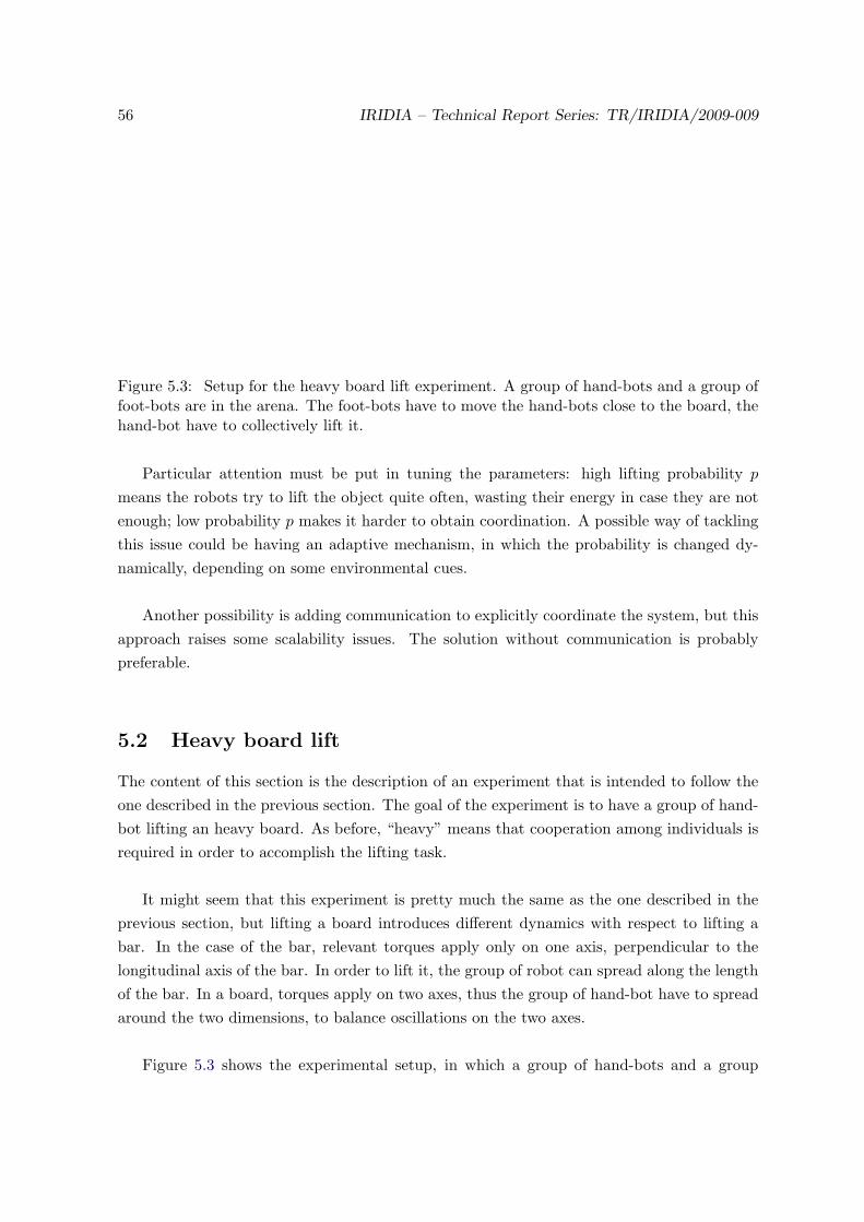
56 IRIDIA – Technical Report Series: TR/IRIDIA/2009-009
Figure 5.3: Setup for the heavy board lift experiment. A group of hand-bots and a group offoot-bots are in the arena. The foot-bots have to move the hand-bots close to the board, thehand-bot have to collectively lift it.
Particular attention must be put in tuning the parameters: high lifting probability p
means the robots try to lift the object quite often, wasting their energy in case they are notenough; low probability p makes it harder to obtain coordination. A possible way of tacklingthis issue could be having an adaptive mechanism, in which the probability is changed dy-namically, depending on some environmental cues.
Another possibility is adding communication to explicitly coordinate the system, but thisapproach raises some scalability issues. The solution without communication is probablypreferable.
5.2 Heavy board lift
The content of this section is the description of an experiment that is intended to follow theone described in the previous section. The goal of the experiment is to have a group of hand-bot lifting an heavy board. As before, “heavy” means that cooperation among individuals isrequired in order to accomplish the lifting task.
It might seem that this experiment is pretty much the same as the one described in theprevious section, but lifting a board introduces different dynamics with respect to lifting abar. In the case of the bar, relevant torques apply only on one axis, perpendicular to thelongitudinal axis of the bar. In order to lift it, the group of robot can spread along the lengthof the bar. In a board, torques apply on two axes, thus the group of hand-bot have to spreadaround the two dimensions, to balance oscillations on the two axes.
Figure 5.3 shows the experimental setup, in which a group of hand-bots and a group

IRIDIA – Technical Report Series: TR/IRIDIA/2009-009 57
of foot-bots are spread around a board to be lifted. In this case, the presence of foot-botsis explicitly taken into account, their role is to reposition the hand-bots around the board,when needed. Concerning the hand-bot, the controller has to extend the one described inthe previous section, since coordination among the robots must be found in order to lift theboard. In addition, the group must be able to understand when is the case of repositioningsome of its members around the board, and communicate this decision to the foot-bots.
The experiment is a nice example of heterogeneous cooperation, with the foot-bot servingthe hand-bot in order to accomplish the global task. For the moment this experiment is justa long term goal since, as mentioned, it needs capabilities that are not yet reliable.

58 IRIDIA – Technical Report Series: TR/IRIDIA/2009-009

Chapter 6
Conclusions and future work
Cooperation among individuals in a swarm of robots can lead the group to perform tasks ina three dimensional space that none of its components could do alone. The work presentedin this report, summarizing the ongoing research, suggests that swarm-robotics approach canbe extended to tasks that develop in three dimensions.
We have described a new robotic concept, called a Swarmanoid, made of an innovative dis-tributed robotic system comprising heterogeneous, dynamically connected, small autonomousrobots. We explained in details the characteristics of each of the robots, with particular at-tention to the hand-bot. We introduced the simulation framework of the Swarmanoid project,focusing on the 3D dynamics physics engine and on the hand-bot model. We presented thefirst simulation results, that concern the development of controllers for the hand-bot:
1. A controller that allows a single robot to grasp objects;
2. A controller that allows two robots to cooperatively lift a bar;
3. A controller that allows two robots to explore a vertical plane;
The contributions of the work presented are:
• The development of a fully functional ODE model of the hand-bot robot, including allthe sensors and actuators. The model is available for all the members of the Swarmanoidproject, and can be used for their research;
• The development of the first controllers for the hand-bot;
The first simulation results confirm that cooperation is beneficial also in tasks that develop inthe third dimension. The experiments presented in Chapter 4 show that the benefits comingfrom cooperation enhance the capability of the system, allowing to perform tasks that go farbeyond the capabilities of a single hand-bot.
59
60 IRIDIA – Technical Report Series: TR/IRIDIA/2009-009
Future Work
The current model of the hand-bot is fully functional and reflects the main characteristic ofwhat will be the real robot. Nevertheless, the parameters of the model need to be tunedproperly, to match the hardware. The exact size and weight of the robot parts is not knownwith precision at the moment and should be measured once the robot is available.
The same applies for the sensors and the actuators. Important parameters are still notknown: the speed of the limbs, the climbing speed, the success rate of the rope launcher, themaximum torques that can be applied by the motors. During the development of the model,those parameters have shown to characterise the behavior of the robot, thus they impact onthe controllers.
Concerning the sensors, noise models need to be determined and then parametrised. Thecameras model needs to be improved: as mentioned in section 2.3, the actual implementationis very simple since it is not known which image characteristic can be extracted using thehardware. The controllers described in this work do not make use of the cameras, but thissensor will be very useful for locating objects and will allow experiments involving vision.
Another direction of the research is to implement the controllers described in this reporton the real robots. The simulator is built to allow transferring the controllers directly to thehardware without any modifications, but it is a known issue that moving from simulation toreality is far from being straightforward. The controllers need tuning to behave in a properway on the robots.
More experiments highlighting the swarm-robotics aspects will be designed and imple-mented using the same approach of simulations followed by real robot validation.
We believe this research work will constitute a small but remarkable step towards theapplication of swarm-robotics in a class of tasks, those developing in three dimensions, thathas been marginally tackled in the literature.
Bibliography
Ahmadabadi, M. N. & Eiji, N. (2001), ‘A ”costrain and move” approach to distributed objectmanipulation’, IEEE Transactions on Robotics and Automation 17, 157–171.
Bayindir, L. & Sahin, E. (2007), ‘A review of studies in swarm robotics’, Turkish Journal ofElectrical Engineering and Computer Sciences 15(2).
Ben-Jacob, E., Cohen, I. & Levine, H. (2000), ‘Cooperative self-organization of microorgan-isms’, Advance in physics 49(4), 395–554.
Beni, G. (2004), From swarm intelligence to swarm robotics, in ‘Proceedings of Workshop onSwarm Robotics, 8th Internationall Conference on Simulation of Adaptive Behavior’, LosAngeles, USA.
Bonabeau, E., Dorigo, M. & Theraulaz, G. (1999), Swarm Intelligence: From Natural to Ar-tificial Systems, Santa Fe Institute Studies in the Science of Complexity, Oxford UniversityPress, New York, NY, USA.
Bonabeau, E., Dorigo, M. & Theraulaz, G. (2000), ‘Inspiration for optimization from socialinsect behaviour’, Nature 406(6791), 39–42.
Camazine, S., Deneubourg, J.-L., Franks, N. R., Sneyd, J., Theraulaz, G. & Bonabeau, E.(2003), Self-Organization in Biological Systems, Princeton Studies in Complexity, PrincetonUniversity Press, Princeton, NJ, USA.
Cao, Y. U., Fukunaga, A. S. & Kahng, A. B. (1997), ‘Cooperative mobile robotics: An-tecedents and directions’, Autonomous Robots 4, 226–234.
Christensen, A., O’Grady, R. & Dorigo, M. (2007), Morphogenesis: Shaping swarms of intel-ligent robots, in ‘AAAI-07 Video Proceedings’, AAAI Press.
Detrain, C. & Deneubourg, J. L. (2006), Physics of Life Reviews 3(3), 162–187.
Dorigo, M. & Stutzle, T. (2004), Ant Colony Optimization, MIT Press, Cambridge, MA.
Dorigo, M., Tuci, E., Mondada, F., Nolfi, S., Deneubourg, J. L., Floreano, D. & Gambardella,L. M. (2005), ‘The SWARM-BOTS project’, Knstliche Intelligenz 4/05, 32–35.
61
62 IRIDIA – Technical Report Series: TR/IRIDIA/2009-009
Garnier, S., Gautrais, J. & Theraulaz, G. (2007), ‘The biological principles of swarm intelli-gence’, Swarm Intelligence 1(1), 3–31.
Gautrais, J., Michelena, P., Sibbald, A., Bon, R. & Deneubourg, J. L. (2007), ‘Allelomimeticsynchronisation in merino sheep’, Animal Behaviour 74, 1443–1454.
Grunbaum, D., Viscido, S. & Parrish, J. K. (2004), ‘Extracting interactive control algorithmsfrom group of schooling fish’, Lecture Notes in Control and Information Sciences 309, 103–117.
J. Fink, M.A. Hsieh, V. K. (2008), ‘Multi-robot manipulation via caging in environments withobstacles’, IEEE International Conference on Robotics and Automation pp. 1471 – 1476.
Jacobi, N. (1997), Half-baked, ad-hoc and noisy: Minimal simulations for evolutionaryrobotics, in P. Husbands & I. Harvey, eds, ‘Proceedings of the Fourth European Conferenceon Artificial Life: ECAL97’, MIT Press, Cambridge, MA, USA, pp. 348–357.
Kube, R. & Zhang, H. (1993), ‘Collective robotics: From social insects to robots’, AdaptiveBehavior 2, 189–218.
Mondada, F., Bonani, M., Guignard, A., Magnenat, S., Studer, C. & Floreano, D. (2005),Superlinear physical performances in a swarm-bot, in ‘In Advances in Artificial Life: 8thEuropean Conf., ECAL 2005’, Springer-Verlag, pp. 282–291.
Mondada, F., Pettinaro, G. C., Guignard, A., Kwee, I. W., Floreano, D., Deneubourg, J.-L.,Nolfi, S., Gambardella, L. M. & Dorigo, M. (2004), ‘Swarm-bot: A new distributed roboticconcept’, Autonomous Robots 17(2–3), 193–221.
Murphy, M. P., Aksak, B. & Sitti, M. (2009), ‘Gecko-inspired directional and controllableadhesion’, Small 5(2), 170–175.
Nouyan, S., Campo, A. & Dorigo, M. (2008), ‘Path formation in a robot swarm: Self-organizedstrategies to find your way home’, Swarm Intelligence 2(1), 1–23.
Reynolds, C. W. (1987), ‘Flocks, herds, and schools: A distributed behavioral model’, Com-puter Graphics 21(4), 25–34.
Seugling, A. & Rolin, M. (2006), Evaluation of physics engines and implementation of aphysics module in a 3d-authoring tool, Master’s thesis, Department of Computer Science,Umeoa University, Sweden.
Smith, R. (2001), ‘Open dynamics engine’, http://ode.org.
Sugar, T. G. & Kumar, R. V. (2002), ‘Control of cooperating mobile manipulators’, IEEETransactions on Robotics and Automation 18(1), 94 – 103.