niversite´ libre de...
TRANSCRIPT

UNIVERSITE LIBRE DE BRUXELLES
Faculte des Sciences Appliquees
CODE - Computers and Decision Engineering
IRIDIA - Institut de Recherches Interdisciplinaires
et de Developpements en Intelligence Artificielle
A CONTROL ARCHITECTURE
FOR A HETEROGENEOUS SWARM OF ROBOTS
The Design of a ModularBehavior-based Architecture
Eliseo FERRANTE
Supervisor:Prof. Marco DORIGO
Co-Supervisor:Dr. Mauro BIRATTARI
Rapport d’avancement de rechercheAcademic year: 2008/2009

2

i
Abstract
We propose a software architecture that can ease and speed up the development process ofcontrollers for heterogeneous swarm systems. It is inherently modular and allows behaviorsto be combined in layers and reused in multiple controllers. This can potentially speed-up the development process of controllers since they become much more readable and wellstructured. We validated the architecture through an experiment of collective navigation andobstacle avoidance using two different types of robots. The experiments show that, usingthe proposed architecture, complex behaviors can indeed be built through the combinationof very simple behaviors.

ii

iii
Acknowledgments
First of all, I would like to thank my supervisor, prof. Marco Dorigo for giving me the pos-sibility to work here at IRIDIA and to do research in Swarm Robotics. I would like to thankalso dr. Mauro Birattari, for the priceless and countless insights he provided me so far. I’mindebted with prof. Andrea Bonarini, which referred me to Marco Dorigo and his wonderfullab. Furthermore, I acknowledge the financial support provided by the Swarmanoid project.
Thank you also to all my friends and colleagues here at IRIDIA, which have also pro-vided an extremely valuable support into my professional and personal life. Amongst them,I would like to thank Nithigno and Carlotto, which have worked with me closely and with-out which this work woudn’t have been accomplished. Thanks also to Marquito, for theunending support and feedback and for always remembering me which are the prioritiesduring a PhD. Thanks also to Arnucci, Rehan, Ali, Antalo, Matteo the Old and Matteo theBald, Manuilio, Franciesci (and his wonderful recipes!), Jeremie, Coligno, Giacomotto (andall the former visiting scientists that have passed through IRIDIA), Prasannotto, Ericco, Sai-fullah, Sabrigna, Gionni, Alex, Francisco, Thomas, Renaud, Christos (and all the others thathave already the privilege to be callable Doctor), etc. . . etc. . . Also, I would like to thank allthe colleaugues in the other labs involved in the Swarmanoid Project.
I would like to thank all my non-IRIDIAn friends that I’ve met here in Brussels, all mydear friends in Milano (hoping they’ve not forgotten me) and that moved away from it andall the others in Santeramo. To all those, I apologize for not including all their names hereas they deserve, leaving with the promise they will be present in the PhD thesis, which is amuch longer and hence suitable document :-).
Last but not least, I would like to thank my parents for supporting me during my studiesthat allowed me to be here, for the continuous support in my decisions, and for always alittle less cloudy place I can always return to.
To all these and to all the others that I unfortunately left out due to the lack of space,THANK YOU!

iv

Contents
Abstract i
Acknowledgments iii
Contents v
List of Figures vii
1 Introduction 11.1 Swarm Intelligence and Swarm Robotics . . . . . . . . . . . . . . . . . . . . . . 1
1.2 Robot Software Architectures . . . . . . . . . . . . . . . . . . . . . . . . . . . . 2
1.3 Overall Goals . . . . . . . . . . . . . . . . . . . . . . . . . . . . . . . . . . . . . 3
2 The Swarmanoid Project 52.1 Overview of the Swarmanoid Project . . . . . . . . . . . . . . . . . . . . . . . . 5
2.2 The Swarmanoid Hardware . . . . . . . . . . . . . . . . . . . . . . . . . . . . . 7
2.2.1 Common Devices . . . . . . . . . . . . . . . . . . . . . . . . . . . . . . . 7
2.2.2 The Foot-bot . . . . . . . . . . . . . . . . . . . . . . . . . . . . . . . . . . 7
2.2.3 The Hand-bot . . . . . . . . . . . . . . . . . . . . . . . . . . . . . . . . . 9
2.2.4 The Eye-bot . . . . . . . . . . . . . . . . . . . . . . . . . . . . . . . . . . 10
2.3 The Swarmanoid Simulation Framework . . . . . . . . . . . . . . . . . . . . . 11
2.3.1 The Simulator Architecture . . . . . . . . . . . . . . . . . . . . . . . . . 12
2.3.2 The Code Organization . . . . . . . . . . . . . . . . . . . . . . . . . . . 14
3 State of the Art of Robot Software Architectures 173.1 Architectures for Single Robot Systems . . . . . . . . . . . . . . . . . . . . . . . 17
3.1.1 The Subsumption Architecture . . . . . . . . . . . . . . . . . . . . . . . 18
3.1.2 Other Single-Robot Architectures . . . . . . . . . . . . . . . . . . . . . . 21
3.2 Architectures for Multiple Robots and for Swarm Robotics . . . . . . . . . . . 23
3.2.1 The ALLIANCE Architecture . . . . . . . . . . . . . . . . . . . . . . . . 24
3.2.2 The ASyMTRe Architecture . . . . . . . . . . . . . . . . . . . . . . . . . 28
v

vi CONTENTS
3.2.3 Probabilistic Swarm Robotics Architecture and Modeling . . . . . . . . 30
4 The Behavioral Toolkit 334.1 Motivation . . . . . . . . . . . . . . . . . . . . . . . . . . . . . . . . . . . . . . . 334.2 The Main Idea . . . . . . . . . . . . . . . . . . . . . . . . . . . . . . . . . . . . . 34
4.2.1 Sequential Behaviors . . . . . . . . . . . . . . . . . . . . . . . . . . . . . 354.2.2 Parallel Behaviors . . . . . . . . . . . . . . . . . . . . . . . . . . . . . . . 37
4.3 Implementation in the Swarmanoid Simulator . . . . . . . . . . . . . . . . . . 394.4 Writing a Behavior Controller . . . . . . . . . . . . . . . . . . . . . . . . . . . . 40
4.4.1 Writing a Behavior combining Sequential Behaviors . . . . . . . . . . . 404.4.2 Writing a Behavior combining Parallel Behaviors . . . . . . . . . . . . 424.4.3 Dealing with Finite State Machines . . . . . . . . . . . . . . . . . . . . . 44
5 Experiments with Modular Behaviors 475.1 Experiment Definition . . . . . . . . . . . . . . . . . . . . . . . . . . . . . . . . 47
5.1.1 High Level Description of the Behaviors . . . . . . . . . . . . . . . . . . 475.1.2 Experimental Setup . . . . . . . . . . . . . . . . . . . . . . . . . . . . . . 48
5.2 Basic Behaviors . . . . . . . . . . . . . . . . . . . . . . . . . . . . . . . . . . . . 495.2.1 Random Walk . . . . . . . . . . . . . . . . . . . . . . . . . . . . . . . . . 495.2.2 Obstacle Avoidance . . . . . . . . . . . . . . . . . . . . . . . . . . . . . 505.2.3 Go to LED . . . . . . . . . . . . . . . . . . . . . . . . . . . . . . . . . . . 505.2.4 Go to Light . . . . . . . . . . . . . . . . . . . . . . . . . . . . . . . . . . 505.2.5 Utility Class . . . . . . . . . . . . . . . . . . . . . . . . . . . . . . . . . . 51
5.3 Phat-bot Assembly . . . . . . . . . . . . . . . . . . . . . . . . . . . . . . . . . . 515.4 Phat-bot Navigation . . . . . . . . . . . . . . . . . . . . . . . . . . . . . . . . . 54
5.4.1 Follow Chain Behavior . . . . . . . . . . . . . . . . . . . . . . . . . . . . 545.4.2 The Push and Pull Behaviors . . . . . . . . . . . . . . . . . . . . . . . . 54
6 Conclusions and Future Work 61

List of Figures
2.1 Foot-bot design. . . . . . . . . . . . . . . . . . . . . . . . . . . . . . . . . . . . . 8
2.2 Hand-bot design. . . . . . . . . . . . . . . . . . . . . . . . . . . . . . . . . . . . 9
2.3 Eye-bot design. . . . . . . . . . . . . . . . . . . . . . . . . . . . . . . . . . . . . 10
2.4 Overall architecture of ARGoS, the Swarmanoid Simulator . . . . . . . . . . . 13
2.5 The package diagram of the Swarmanoid simulator . . . . . . . . . . . . . . . 14
2.6 The class diagram of a controller which does not exploit the behavioral toolkit 15
3.1 Schema of the mobile robot control system architecture used earlier than theintroduction of the subsumption architecture . . . . . . . . . . . . . . . . . . . 18
3.2 Schema of the mobile robot control system architecture used in the subsump-tion architecture . . . . . . . . . . . . . . . . . . . . . . . . . . . . . . . . . . . . 19
3.3 The role of levels of competence in the subsumption architecture . . . . . . . 19
3.4 Schema representing one module in the subsumption architecture . . . . . . . 20
3.5 An example of subsumption architecture with level of competence 0 only . . 21
3.6 An example of subsumption architecture with level of competence 0 inte-grated with level 1 . . . . . . . . . . . . . . . . . . . . . . . . . . . . . . . . . . 22
4.1 The behavioral toolkit architecture instantiated in the case of serial behaviorsonly. B0, B1 and B2 denote behaviors, whereas L0, L1 and L2 denote levels ofcompetence . . . . . . . . . . . . . . . . . . . . . . . . . . . . . . . . . . . . . . 35
4.2 The behavioral toolkit architecture instantiated in the more general case ofparallel behaviors. B0, B1 and B2 denote behaviors, whereas L0, L1 and L2denote levels of competence . . . . . . . . . . . . . . . . . . . . . . . . . . . . . 37
4.3 The class diagram of the behavioral toolkit inside ARGoS . . . . . . . . . . . . 39
4.4 The code of a sample behavior controller . . . . . . . . . . . . . . . . . . . . . 40
4.5 A small subsection of the CCI BehaviorController class . . . . . . . . . . 41
4.6 A sample, atomic behavior . . . . . . . . . . . . . . . . . . . . . . . . . . . . . . 41
4.7 A sample behavior combining two other behaviors sequentially: random walkwith obstacle avoidance . . . . . . . . . . . . . . . . . . . . . . . . . . . . . . . 41
vii

viii LIST OF FIGURES
4.8 A classical controller (i.e. not exploiting the behavioral toolkit) performingrandom walk with obstacle avoidance . . . . . . . . . . . . . . . . . . . . . . . 42
4.9 A sample behavior combining two other behaviors parallely . . . . . . . . . . 434.10 A sample template behavior showing how to use the FSM tool . . . . . . . . . 444.11 The diagram of the very simple FSM implemented in Figure 4.10 . . . . . . . 454.12 A sample template behavior showing how to use the FSM tool to query be-
haviors about their state . . . . . . . . . . . . . . . . . . . . . . . . . . . . . . . 46
5.1 A simulated phat-bot in all its beauty . . . . . . . . . . . . . . . . . . . . . . . 485.2 The overall organization of the assemble and move behavior . . . . . . . . . . . 495.3 The FSM of the of the assemble behavior . . . . . . . . . . . . . . . . . . . . . . 525.4 Eye-bot design. . . . . . . . . . . . . . . . . . . . . . . . . . . . . . . . . . . . . 535.5 The FSM of the of the pull and push behaviors . . . . . . . . . . . . . . . . . . . 555.6 Diagram showing the range of activation of the proximity sensors in the ob-
stacle avoidance behavior during phat-bot navigation . . . . . . . . . . . . . . . 575.7 Push VS Pull Behavior. . . . . . . . . . . . . . . . . . . . . . . . . . . . . . . . . 595.8 Box and wisker plot comparing the time delays of push and pull behaviors,
showing there is no substantial difference between the two. Some outliers arepresent in both cases. . . . . . . . . . . . . . . . . . . . . . . . . . . . . . . . . . 60

Chapter 1
Introduction
This work deals with the design and the implementation of a software architecture that canbe employed for the development of controllers for heterogeneous group of robots. With theproposed architecture, modularity and code reuse is made possible, yielding to a significantspeed-up in the development of controllers.
The aim of this first chapter is to introduce the main scientific domains where this workshould be placed, i.e. swarm intelligence and robotics. We then outline the goal of thisdocument together with the structure of the entire document in the last section.
1.1 Swarm Intelligence and Swarm Robotics
Swarm intelligence (commonly abbreviated with SI) is a sub-field of artificial intelligence. Itstudies principles such as self-organization, decentralization and emergence of collectivebehaviors. The term was first introduced by Beni and Wang (1989) in the context of cellularrobotic systems.
Swarm intelligence systems consist typically of a population of relatively simple agentswhich interact only locally with each other and with their environment, without globalknowledge about their own state and of the state of the world. Furthermore, the agentsfollow often very simple rules and exhibit, to a certain degree, random interactions betweeneach other. A recurrent property of these systems is the emergence of “intelligent” globalbehaviors, without centralized control/
Swarm intelligence is often inspired from the behavior of social insects and from othergroups of animals. Examples include ant colonies (Detrain and Deneubourg, 2006), birdflocking (Reynolds, 1987), animal herding (Gautrais et al., 2007), colony of bacteria (Ben-Jacob et al., 2000), and fish schooling (Grunbaum et al., 2004).
The following are desirable properties of swarm intelligence systems:
• the system is composed of many, relatively homogeneous agents;
1

2 CHAPTER 1. INTRODUCTION
• the agents are relatively simple both in structure and in their behavior;
• interactions amongts agents are only local;
• control is fully distributed;
• the global behavior is not encoded in the system but emerges from the interactionamongst the agent and is more rich with respect to the behaviors of individual agents;
• the system is robust and adaptive with respect to unexpected event in the environmentor in the system itself.
Swarm intelligence is composed of several sub-fields. Amongst them, we can find:swarm based optimization techniques like ant colony optimization (Dorigo and Stutzle,2004) and particle swarm optimization (Kennedy and Eberhart., 2001); data mining (Abra-ham et al., 2006); network routing (Caro and Dorigo, 1998); and swarm robotics (Dorigoand Sahin, 2004). Amongst all the sub-fields of swarm intelligence, the present work can beplaced in swarm robotics.
Swarm robotics is a alternative approach to robotics which tackles some issues presentin classical robotics. Such issues include the increase in complexity of the system as thetask becomes more complex or the high sensitivity to faults. Swarm robotics consists in theapplication of principles of swarm intelligence to the field of robotics (Dorigo and Sahin,2004).
Swarm robotic systems allow the development of cheaper, less complex robots, whichare more robust. Other properties of the swarm robotic approach are flexibility, adaptability,redundancy and fault tolerance. For a review on swarm robotics, see Bonabeau et al. (1999)or Beni (2004). Examples of success applications of swarm robotics include flocking (Turgutet al., 2008), morphogenesis and self-assembly (Christensen et al., 2007; Groß and Dorigo,2007), fault detection (Christensen et al., 2008), path formation and prey retrieval (Nouyanet al., 2008), coordinated behaviors (Sperati et al., 2008) and collective transport (Groß andDorigo, 2008).
1.2 Robot Software Architectures
This work can also be placed in the domain of robot architectures. A robot architecture primar-ily refers to the software and hardware framework for controlling the robot. In particular, itconcerns the development of software modules and the communication between them.
Robotic systems are complex and tend to be difficult to develop. They integrate multiplesensors and actuators, they might have many degrees of freedom and must reconcile hardreal-time systems with systems which cannot meet real-time requirements. These architec-
1.3. OVERALL GOALS 3
tures, however, have so far been task and domain specific and have lacked suitability to abroad range of applications.
The first trend, during the 50s, was to produce architectures able to integrate reasoningand planning systems common to the mainstream AI systems of those times. A subsequenttrend has focused on behavior-based or reactive systems. These systems are characterizedby tight coupling between sensors and actuators, minimal computation, and decompositionof the problem which is based on behaviors themselves. When also behavior-based archi-tectures reached their limits, the following step was to produce architectures that integratedplanning with behavior-based control: the so-called hybrid architectures. However, this his-torical evolution (that will be described in more details in Section 3.1) has mainly concernedsingle robot systems.
1.3 Overall Goals
Although architectures for multi-robot systems have been developed (see Section 3.2), theydo not immediately scale to swarm robotics systems. Hence, an interesting topic of research,we believe, is to investigate whether it is possible to develop an architecture where sev-eral individual-level behaviors can be orchestrated in order to guarantee the emergence of aglobal behavior capable of solving the task at hand. To achieve this, one can use the worksdescribed in Section 3.2.3 as an inspiration.
Furthermore, we believe that behavior-based architectures are a central cornerstone, i.e.they represent the essential lower layer for the development of individual level behavior thatcould then be integrated by the introduction of an extended architecture for swarm robotics.Hence, in Chapter 4, we introduce our work: the behavioral toolkit. The behavioral toolkit isa modular, behavior-based architecture developed for the Swarmanoid project (described inChapter 2) in the context of swarm robotics. In this work, we will focus on the software as-pect: we want our architecture to facilitate writing modular, effective and most importantlyhighly readable object oriented code describing behaviors, in order to speed up the efficiencyof the development process. In Chapter 5 we test the proposed architecture on a heteroge-neous swarm robotics task which involves the assembly of a robotic entity composed of twotypes of robots and its navigation in a complex environment with obstacles. We concludethe present document in Chapter 6 with final remarks and proposals of extensions to theproposed architecture.

4 CHAPTER 1. INTRODUCTION
Chapter 2
The Swarmanoid Project
This chapter is devoted to the introduction of the Swarmanoid project. It consists of a swarmrobotics project that puts particular emphasis on the heterogeneity aspect. In this chapter, wefirst provide an introduction to the project as a whole. Subsequently, we briefly introduce thekey components of the project, whose development is, at the time of writing, still on-going,i.e. the hardware and the simulation software.
2.1 Overview of the Swarmanoid Project
The creation of a flexible and autonomous robotics platform that is able to support humansin many of their activities has long been under research. Research in robotics has been pro-gressing in different directions, amongst which we can find mobile robotics and humanoidrobotics.
Mobile robotics has, as a key driving force in its development, the reduction of humanintervention in potentially dangerous or unaccessible applications. Examples of such ap-plications are cleanup of toxic waste, nuclear power plant decommissioning, planetary ex-ploration, security, surveillance, etc. . . On the other hand, research in humanoid robotics hasmainly been motivated by the need of supporting ordinary human daily activities. Assis-tance of elderly, sick or disabled people are key examples, as well as automation of ordinarybut repetitive activities (mainly held indoor) such as receptionists and other tasks that re-quire interaction with people.
Autonomous robotics can be also classified from another, orthogonal perspective. Onone hand, a first approach is clearly to design and build a single robot, able to address a par-ticular application. Such a robot would need to have all the capabilities in terms of sensors,actuators and control able to complete its task. Such an approach can be feasible for smaller-scale applications. However, as the complexity of the tasks increase, single robot approachis destined to not scale well enough due to the required complexity and cost.
An alternative approach is to design and build teams composed of multiple robots that
5

6 CHAPTER 2. THE SWARMANOID PROJECT
can autonomously and collectively solve the task. Potential advantages of using a dis-tributed mobile robot systems include the reduction of the total cost, since each individualrobot does not need to be over complex as in the single robot case. Also, designing a solutioncan be easier than in the case mentioned above. Other advantages include robustness, faulttolerance and parallelism. This means that, in a team of robots, a subset of them can takeover a task that was not completed by other robots due to failure or inefficiency. Further-more, multiple sub-tasks can be executed at the same time, thus increasing the whole systemperformance.
Swarm robotics is a very particular and peculiar sub-area of collective robotics. As al-ready mentioned in Section 1.1, particularly important in swarm robotics are aspects such asself-organisation, decentralisation, local perception and communication.
Within the framework of swarm robotics, the Swarmanoid Project is a futuristic projectthat temporally and logically follows the Swarmbots Project (Dorigo et al., 2004; Mondadaet al., 2004). As its predecessor, it is funded by the European Commission. Five researchlaboratories scattered through Europe are part of it: IRIDIA at Universite Libre de Bruxellesin Belgium, Istituto di Scienze e Tecnologie della Cognizione at Consiglio Nazionale delleRicerche in Italy, Laboratoire de Systemes Robotiques and Laboratory of Intelligent Systemsat Ecole Polytechnique Federale de Lausanne in Switzerland and Istituto Dalle Molle di Studisull’Intelligenza Artificiale at Universita della Svizzera italiana in Switzerland.
The Swarmanoid project is different with respect to most current studies in swarm roboticsystems, which have focused on robotic swarms in which components are physically andbehaviourally undifferentiated. In the Swarmanoid project, in fact, the focus is on how todesign, realise and control a heterogeneous swarm robotic system capable of operating in afully 3-dimensional man made, indoor environment. The swarm is composed of heteroge-neous, dynamically connected, small autonomous robots of three types: eye-bots, hand-bots,and foot-bots.
The Swarmanoid project can be seen as an attempt to unify mobile swarm robotics withhumanoid robotics. The vision is in fact the creation of some sort of humanoid swarm. Thedirection that is used to go towards humanoid swarming is specialization. The three robottypes are introduced are each specialized on particular capabilities: eye-bots are specializedin perception and supervision, whereas hand-bots focus on manipulation and foot-bots onnavigation and transport. More in particular:
Eye-bots fly or attach to the ceiling. Thanks to their positioning capabilities and to theircamera, they are able to quickly explore the environment and locate targets, interestingobjects or areas.
Hand-bots are intended to retrieve and manipulate objects located on walls, shelves, ortables. They can climb walls and obstacles by means of a rope they can launch in orderto attach to the ceiling.

2.2. THE SWARMANOID HARDWARE 7
Foot-bots are wheeled robots equipped with a rigid gripper used to assemble with otherfoot-bots, transport hand-bots or target objects.
In the following sections we present the hardware capabilities of the robots. Finally, asimulation environment is also introduced. It has been developed to ensure rapid prototyp-ing and testing of robot behaviors.
2.2 The Swarmanoid Hardware
In this section we briefly present the hardware of the robots of the Swarmanoid project. Wefirst present the hardware capabilities that are shared between the robots, followed by thecharacterization each robot individually.
2.2.1 Common Devices
Some hardware capabilities are common to all robots. They consists ofn:
• The main processor board: the Freescale i.MX31 ARM 11 processor, a low-energy533 MHz processor with a complete collection of subsystems such as USB host con-troller, integrated camera interface and SD card. The main board features 128 MB ofDDR RAM and 64 MB of flash.
• The range and bearing subsystem, which is a module that allow local and situatedcommunication in between the robots, achieved through the integration of radio andinfrared technologies.
• The CAN bus, used to interconnect the different micro-controllers arbitrating each in-dividual sensor/actuator module, and the main board.
• The Pixelplus 2.0 MegaPixels CMOS camera.
2.2.2 The Foot-bot
In the Swarm-bots Project, the s-bot provides the basic robotic platform. It consists in a smallscale robot with many sensors and actuators. S-bots are able to connect to each other witha rigid gripper in order to form a Swarm-bot. The success of the Swarm-bots Project andespecially of its s-bot suggested that the foot-bot design should be based on it. A moreadvanced prototype of the s-bot is the marXBot, a modular robot with higher computationalpower and more sensors with improved accuracy.
The foot-bot has been therefore based on the marXBot and Figure 2.1 details the some ofits components: the overall design; the base of the robot that includes the wheels actuatedby 2W motors; the LED ring; the gripper. Other key hardware components include: a set

8 CHAPTER 2. THE SWARMANOID PROJECT
(a) (b)
(c) (d)
Figure 2.1: Foot-bot design: (a) the foot-bot CAD model, (b) the base of the foot-bot that isprototyped at the time of writing, (c) the foot-bot LED ring and (d) the foot-bot gripper
of 24 proximity sensors placed in a ring facing outside; 8 proximity sensors facing down; 4contact ground sensors; a rotating long-range1 infrared distance sensor; an omnidirectionalcamera and a camera looking up (whose common technology has already been described in2.2.1). Additionally, the foot-bot has a hot-swappable battery, and a super-capacitor keepsthe robot alive while the battery is being exchanged.
1Up to 1.5 m.

2.2. THE SWARMANOID HARDWARE 9
(a) (b)
(c) (d)
Figure 2.2: Hand-bot design: (a) the hand-bot CAD model, (b) a more detailed hand-botCAD model, (c) the hand-bot prototype developed at the time of writing and (d) the hand-bot gripper grasping a book
2.2.3 The Hand-bot
The hand-bot represents a still unexplored robotic platform. It is designed to be a relativelylow-cost, energy saving, light weight robot able to launch a rope, climb on vertical supportsand manipulate objects located on the vertical plane (for example on shelves).
Figure 2.2 details some of the hand-bot’s components. Other key components are: therope launcher, which is made of 4 motors (one for recharging the spring and unlocking thelauncher, one for the fast rewind of the cable when the magnet is detached, one for movingthe hand-bot up and down the rope, and one servo-motor for connecting the previous motorto the rope driving system); the head, which is the attach and rotation point for the arms;a camera with a fish-eye lens placed in the head; two powerful motors to drive each armindependently and a third motor responsible for rotating the arms with respect to the body;the grippers, which are placed at the end of the arm and consist of two motors: one forrotation and one for grasping.
The hand-bot can also move on the ground thanks to foot-bots which can grip it. Climb-

10 CHAPTER 2. THE SWARMANOID PROJECT
(a) (b)
(c) (d)
Figure 2.3: Eye-bot design: (a) one of the first prototypes, (b) one of the last prototype at thetime of writing, (c) the eye-bot pan and tilt camera and (d) ceiling attachment mechanism
ing to reach objects located on shelves is achieved through a rope with magnetic attachmentdevice. The rope is launched with a mechanical device allowing also the rewind of the cable.This requires the ceiling to be ferro-magnetic.
Manipulation of objects requires a more evolved gripper than the one mounted on thefoot-bot. The current prototype is depicted in Figure 2.1d.
2.2.4 The Eye-bot
Similarly to the hand-bot, the design of a flying robot such as the eye-bot is very difficult.Its design and prototyping has been through a lot of phases (Figure 2.3a and 2.3b showstwo of the prototypes of the robot). The eye-bot has the following capabilities: it has fullyautonomous stability control including pitch, roll, yaw and altitude; the ability to hover andmanoeuvre in an indoor environment; it can attach to the ceiling to save energy and to allowfor a stable visual field of view; it has an omni-directional vision systemfor visual objectdetection and a visual colour signaling system for low-level communication between robots.
The robot is based on a quadrotor design. It will be equipped with an optic-flow sensor,which will be used to detect and avoid drifts in random directions.
The ceiling attachment device (Figure 2.3d) is located centrally at the top of the robotstructure. Attachment to a ferro-magnetic ceiling is achieved by using a toroidal (passive)

2.3. THE SWARMANOID SIMULATION FRAMEWORK 11
magnet with an attractive force of 2.5kg. The detachment mechanism consists in a mechani-cal lever that pushes a carbon fiber rod through the center of the toroid.
The flight computer is located centrally at the top of the eyebot structure on the secondlevel of the avionics board stack. It is in charge of all the low-level stability control andhouses the critical stability sensors: gyros, accelerometers, pressure altitude, ultrasonic alti-tude and magnetometer.
The vision system 2.3c system is capable of panning 360 degrees in the horizontal planeand tilting 90 degrees from vertical to horizontal. It uses the same camera described in 2.2.1.A Red-Green-Blue (RGB) colour signaling light will be placed directly on the bottom of theeye-bot which can be used as a visual communication device between robots.
Finally, a omni-directional distance scanner is also available, which consists of two in-frared triangulation sensors facing opposite directions.
2.3 The Swarmanoid Simulation Framework
In the context of the Swarmanoid project, a software simulation framework was also devel-oped under the name of Autonomous Robots Go Swarming (ARGoS). By the term simulationframework we denote a set of tools that not only include a simulator but also other tools thatare needed to ensure certain properties about the system as described in the following.
A simulator is a computer program that attempts to model a system for which a simpleanalytical solutions cannot be found easily. Simulation allows the study of such a systemunder a large variety of situations or scenarios.
Simulators play also an essential role in the development of robot controllers. Simulatedexperiments are usually much faster than real ones and simulated robots do not have hard-ware failures or battery exhaustion (unless this is an explicitly desired property). Further-more, simulations do not need to take into account purely technical issues such as calibrationof sensors and actuators. Unfortunately, there is no guarantee that the controllers developedin simulation will work as expected in real robots. Hence, a desirable (but not entirely at-tainable) qualitative property of simulators is the possibility to have a seamless transitionbetween simulation and reality.
There are several approaches to tackle the above problem. A naive solution is trying tomodel sensors and actuators of the robots as precisely as possible as for making the differ-ence between simulation and reality negligible. Anyway, it is practically unfeasible to per-fectly simulate reality (Frigg and Hartmann, 2006), and the more the model becomes morefaithful to reality, the more simulation become more complex and hence slower.
On the other hand, physics simulation could be in principle avoided completely. Somesensors such as ground sensors, light sensors and infrared proximity sensors can be imple-mented by sampling real readings taken from various positions and orientations with respect

12 CHAPTER 2. THE SWARMANOID PROJECT
to other objects of the environment. The final result is a large numerical table containing therecorded samples that is fairly easy to import and fast to access at run-time. Nevertheless,obtaining such a table is a time-consuming and error-prone activity. Furthermore, differentrobots with the same sensors are likely to give significantly different readings due to differ-ences in the electronics. Lastly, this technique does not appear applicable to sensors such asdigital cameras.
A commonly utilised method to ease to transfer controllers to real robots is adding noiseto sensors reading and actuators outputs (Jacobi, 1997). This is a reasonable approach be-cause real sensors and actuators are indeed noisy. Additionally, noise injection softens thenatural differences between different physical sensors and actuators. The computational im-pact of noise addition is negligible but, thanks to it, resulting controllers are more robust andmore easily transferable.
The development of a simulator is of critical importance inside the Swarmanoid project.One of the key additional motivation besides the ones highlighted above is the fact thatrobots are developed during the course of the project and they are not ready before the lastperiods (at the time of writing, they are still in development). Hence, the only methodologythat allows the development of robot controllers before the robots are ready is to use a soft-ware simulator. Furthermore, users should also be allowed to seamlessly transfer controllersdeveloped in simulation into the real robots. One way to achieve this is by allowing the samecode to be compilable both for the simulator and for the robotic hardware platform withoutany further intervention. On the other hand, sensors and actuators of the robots need to besimulated as much accurately as possible, thus needing a continuous interaction betweenpeople working in hardware and software.
In the following sections we highlight how the design and the code organization of AR-GoS and of the entire simulation framework can successfully tackle the above issues. ARGoSis also important for the aim of this report since our proposed architecture (described laterin Chapter 4) has been designed within this framework.
2.3.1 The Simulator Architecture
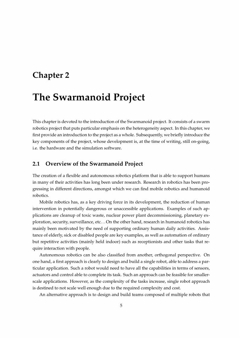
Figure 2.4 depicts the architecture of ARGoS. The key components of the architecture are:
The Swarmanoid Space is the space where all objects live;
The Physics engines are responsible for updating the status (i.e. position, orientation) ofthe objects they are responsible for;
The Visualization engines are in charge of drawing the scene either under the form ofimmediate visualization for the user, or in form of text data, or potentially as a highquality movie (at the time of writing not yet implemented);
2.3. THE SWARMANOID SIMULATION FRAMEWORK 13
Figure 2.4: Overall architecture of ARGoS, the Swarmanoid Simulator
Sensors and Actuators are used by the robots to interact with the environment;
Robot Controllers are programs that associate sensory data to actuator’s signals in orderto encode the behavior of the robot.
The Swarmanoid simulator has been designed to support the possibility of running dif-ferent physics engines independently during an experiment. For instance, foot-bots mightbe simulated in a 2D physics engine, whereas hand-bots and eye-bots could be managedby another, or even other two, separated 3D physics engines. This key feature has been ob-tained by decoupling the space in which all objects live from the physics engines space. Theformer, global space goes under the name of Swarmanoid Space.
Sensors and actuators are classified in order to provide a coherent structure for their de-velopment. Some sensors and actuators rely on physics equations, whereas other sensors,such as the camera, simply rely on positional information to compute their readings. Like-wise, some actuators do not need any physical information to perform their actions. Sensorsand actuators that are physics dependent and must be reimplemented for each differentphysics engine are denoted as specific, whereas those that do not need such interaction aredenoted as generic.
The design of ARGoS is highly modular. Each box in Figure 2.4 has been implementedas a plugin. The user can code his own version of each module, and easily inform the systemabout its existence. Compatibility and interoperability are guaranteed by the interfaces that

14 CHAPTER 2. THE SWARMANOID PROJECT
Common
SimulatorReal robot User
Figure 2.5: The package diagram of the Swarmanoid simulator
will be described in the following section. Particular emphasis will be put on the commoninterface, which left out in this section and is the key component that favors an easy transferbetween simulation and real robot.
2.3.2 The Code Organization
Figure 2.5 depicts the software packages in which the code of the entire simulation frame-work has been divided, and their mutual dependencies. The division in packages has beendesigned to maximize code reuse while keeping the functionalities logically separated. Aswe can see, there are four packages: common, simulator, real robot and user.
The common package defines an interface to each of the robot’s hardware. It is sharedacross simulated and real robots and enables the user to access the capabilities of arobot in the same way both in simulation and on the real hardware. Additionally, it in-cludes a set of general purpose utilities: we can find string utilities, common definitions,logging facilities, mathematical definitions and functions, and so on. The most impor-tant part of this package is the definition of the common control interface, describedlater;
The simulator package contains all the logic and data for the simulator itself. In this pack-age, the common control interface is implemented to provide simulated sensors andactuators. Moreover the Swarmanoid Space, the physics engines and the visualiza-tions as depicted in Figure 2.4 are all included in this software package.
The real robot package contains the toolchain and the wrapper to access the specific robotplatform and additional tools. Its purpose is to provide a tool set to compile softwarefor the real robots.
The user package allows each user to develop controllers on an individual basis.

2.3. THE SWARMANOID SIMULATION FRAMEWORK 15
Figure 2.6: The class diagram of a controller which does not exploit the behavioral toolkit
The common package is the package containing the common interface. The commoninterface provides a standard way of accessing the robot hardware APIs. It is written inthe C++ programming language. Every controller developed as part of the Swarmanoidproject, whether in simulation or on the real robots will access the hardware (real or simu-lated) through this common interface. Since each robot’s hardware is potentially different,also the platform and the set of tools is different as well. Furthermore, heterogeneous in-terfaces with sensors or actuators might be associated even to a single robot platform, forexample because some sensors or actuators might be developed independently as modules.The common interface is an essential component, as it allows controllers to be written onlyonce for both platforms (the one available to the simulator, for example a PC with Linux, andthe one available on the robot).
It is out of the scope of this document to provide an in-depth description of all the classesincluded in the simulator framework (for a more detailed overview refer to Pinciroli (2006)).However, before concluding, we just highlight in Figure 2.6 the class diagram of the controlinterface while not exploiting the architecture presented in this report. A user made controlleris just a straightforward implementation of the common interface class CCI Controller,providing the definition of the functionalities of a controller that are common to the simulationand the real robot. Here, we use a color convention that is common to the one that will beused later, in Chapter 4. According to this convention, a red region denotes a set of classesbelonging to the common package, whereas blue denotes classes belonging to the userpackage. In Chapter 4, we will show how this architecture changes after the introduction ofthe behavioral toolkit.

16 CHAPTER 2. THE SWARMANOID PROJECT

Chapter 3
State of the Art of Robot SoftwareArchitectures
The aim of this chapter is provide a brief but structured review of work that has been done inthe field of robot architectures.
Most of the effort in the area concern single-robot architectures, where much focus hasbeen put into augmenting the robot cognitive capabilities in order to solve complex tasks,often resulting in architectures that are quite complex and of composite nature. On the otherhand, some effort has been put in order to provide architectures for multi-robot or swarmsystems. Such architectures do not put much stress on the cognitive capabilities of eachindividual robot, but they rather focus on the orchestration of behaviors in-between severalrobots.
The rest of the chapter is organized as follows. In Section 3.1 we review the pioneerarchitectures developed for single-robot systems, while also sketching very briefly what havebeen their follow-ups. Subsequently, in Section 3.2, we review what we believe are the mostrepresentative works done in architectures for multi-robot systems.
3.1 Architectures for Single Robot Systems
The first time researchers felt the need for having a robot architecture dates back in the1960s with the “Shakey” robot by Nilsson (1969). At that time, all attempts were focused ontrying to apply artificial intelligence techniques to robotics in a straightforward way. Thosetechniques heavily relied on the presence on a internal model inside the robot. To deal withthis, the architecture that was wide spread at that time was called SPA (Sense Plan Act). Itwas composed of three subsystems: the sensing sub-system was translating sensory datainto the internal robot model; the planning sub-system took the internal world model and agoal and generated a plan achieving the goal; the execution sub-system took the plan and
17

18 CHAPTER 3. STATE OF THE ART OF ROBOT SOFTWARE ARCHITECTURES
Figure 3.1: Schema of the mobile robot control system architecture used earlier than theintroduction of the subsumption architecture
converted it into actions for the robot.The above control paradigm was widely used in robotics for many years. In the early
1980s, researchers realized that SPA had many problems: first, the planning phase was veryslow or unfeasible for most of the real world problems; second, acting in the real world byonly using an internal model without relying to the sensors was counterproductive especiallyin changing environments; third, no direct mapping exists between sensors to an internalworld, due also to noise in the sensors. Some new paradigms were developed in order toface the issue, amongst which the most influential was, without doubts, the seminal work ofBrooks (1986).
The aim of this section is to briefly introduce the subsumption architecture (in Sec-tion 3.1.1) together with the general trend that was followed in the following years until nowa-days (in Section 3.1.2).
3.1.1 The Subsumption Architecture
The subsumption is an architecture which is composed of layers, each of which is composedof asynchronous modules which communicate using channels with minimal requirements.Each module is an instance of a very simple finite state machine (Minsky, 1967), whichinterconnects sensors to actuators directly. These modules were renamed as behaviors.The presence of multiple layers or level of competence induces also an implicit arbitrationmechanism, as we will see later.
The SPA architecture widely used before the subsumption can be exemplified in theschema of Figure 3.11. On the other hand, Brooks’ subsumption consists in a verticalschema as the one depicted in Figure 3.2. As we can see, the functional decompositionin modules is almost the same in both architectures. What changes is that, in the traditionalapproach, the problem is decomposed according to the internal workings of the solution,that is intermediate modules like planning are not directly connected to sensors and actua-tors. On the other hand, in the subsumption each module (including planning) always faces
1All figures in this section were taken from Brooks (1986)

3.1. ARCHITECTURES FOR SINGLE ROBOT SYSTEMS 19
Figure 3.2: Schema of the mobile robot control system architecture used in the subsumptionarchitecture
Figure 3.3: The role of levels of competence in the subsumption architecture
the outside world, leading to a representation that is designed on the basis of the desiredexternal manifestations of the robot control system.
The basic concept of the subsumption architecture is the one of the level of competence.Figure 3.3 shows how this concept is put into use. A level of competence collects a setof behaviors that pertains to some class. Classes are defined according to some informalspecification. The higher the level of competence, the more specific the class of behaviorsshould be, i.e. the more constraints it should put on the behaviors. This organization alsoinduces a coordination mechanism amongst different levels: behaviors at an higher level ofcompetence can inhibit signals coming from lower level behaviors (Figure 3.4).
Consider the example proposed by Brooks (1986). A level zero level of competence can

20 CHAPTER 3. STATE OF THE ART OF ROBOT SOFTWARE ARCHITECTURES
Figure 3.4: Schema representing one module in the subsumption architecture
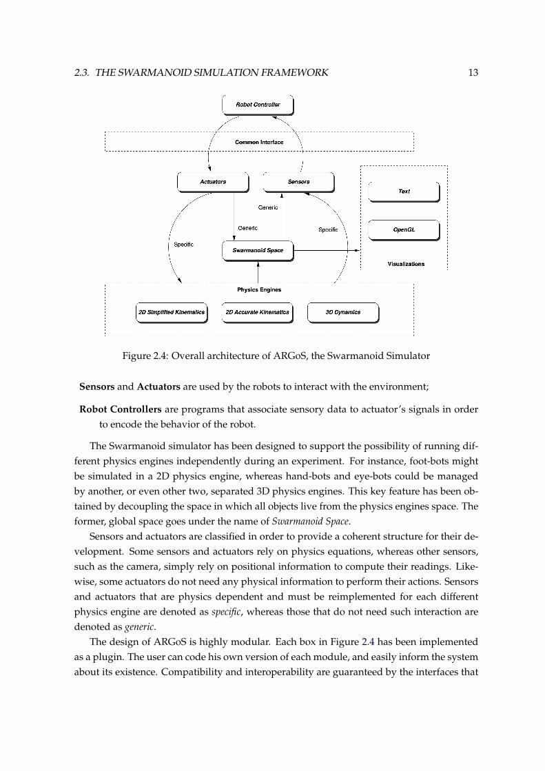
be represented by the behaviors depicted in Figure 3.5. We assume the designer has pro-vided a set of behaviors that are able to let a robot move away from obstacles in a clutteredenvironment. Imagining an environment without obstacles, the result of level 0 behaviorshas the robot probably ending up in the middle of it. To get a more interesting behavior wecan add a further level (Figure 3.6). Here, we can imagine having a wander module contin-uously generating random headings, and an avoid module which will perform a more cleverobstacle avoidance by combining some of the output of the earlier layer with the output ofthe wander module. In this example, when the presence of an object is detected, the outputof the wander module will be overwritten in order to produce a trajectory able to avoid theobject. If the object is not present, the wander behavior will have control of the trajectorygeneration, producing a behavior that can explore the environment aimlessly. As a result,the two combined layers produce a robot behavior that is able to aimlessly explore the en-vironment while avoiding obstacles. On top of these two, other layers can be engineered inorder to face more restrictive specifications, for example in order to construct a map of theenvironment.
In his original work, Brooks (1990) proposed also a Behavioral Language, which wasmainly inspired by the LISP2 functional programming language. More recently, implemen-tations in more modern imperative programming languages were proposed, for exampleby G. Butler (2001).
One of the main advantages of the subsumption architecture is that behaviors can be
2McCarthy, John (1979-02-12). ”The implementation of Lisp”. History of Lisp. Stanford University.http://www-formal.stanford.edu/jmc/history/lisp/node3.html.
3.1. ARCHITECTURES FOR SINGLE ROBOT SYSTEMS 21
Figure 3.5: An example of subsumption architecture with level of competence 0 only
constructed, tested and debugged independently. The introduction of a new behavior or ofa new level of competence does not require the designer to rethink all the modules that shehas produced so far together with their interconnection, as it was the case for the traditionaldesign. Furthermore, subsumption proved to be successful when compared to SPA robots:the latter were slow and ponderous, whereas the former produced robots that were fast andreactive. A changing environment was not an issue for them since they constantly sensedthe world and reacted to it. Finally, the subsumption architecture served as an inspiration forseveral other follow-ups. These subsequent contributions will be very briefly outlined in thecoming section.
3.1.2 Other Single-Robot Architectures
The aim of this section is to briefly sketch some (and hopefully the most important) of theremaining architectures for single robot systems. This small review does not have the am-bition to be comprehensive. For a more complete review, refer to specialized books suchas Siciliano and Khatib (2008), Arkin (1998), Kortenkamp et al. (1998), Murphy (2000) andSiegwart and Nourbakhsh (2004).
Motor Schemas Developed by Arkin (1989), it was the natural follow-up of the subsumption.It is a biologically inspired approach, where motor and perceptual schemas are dy-namically connected to each other. Each schema generates response vectors basedon outputs of the perceptual schemas, which are then combined together in a waysimilar to potential fields.

22 CHAPTER 3. STATE OF THE ART OF ROBOT SOFTWARE ARCHITECTURES
Figure 3.6: An example of subsumption architecture with level of competence 0 integratedwith level 1
AuRA As well developed by Arkin (1998), it enhances motor schemas by adding a naviga-tion planner and a plan sequencer based on finite-state acceptors (FSAs). It was oneof the first hybrid architectures.
MITRE Introduced by Bonasso (1991), it was the first 3T (three tier) architecture, which con-sists in three interacting layers, namely planning (high level), sequencing or execution(intermediate level) and real-time control (low level).
ATLANTIS Introduced by Gat (1992), it is also a 3T architecture. The central concept tothe ATLANTIS architecture is that of ”activities at varying time scales”. At short timescales the world is both dynamic and very precise, as the time scale grows the worldbecomes more static and more abstract. As a result, each layer addresses a differenttime scale.
Intelligent Control Developed by Saridis (1995), it is also a 3T architecture. Here, the con-trol layer is implemented through low level servo systems, the sequencing layer throughPetri net transducers, and the planning level through Boltzmann neural networks.
LAAS Another 3T architecture developed by Alami et al. (1998), it consists in a lower layer

3.2. ARCHITECTURES FOR MULTIPLE ROBOTS AND FOR SWARM ROBOTICS 23
composed of parameterizable modules written in a module generator (GenoM), a se-quencer layer that is very simple and purely reactive and simply maps the highest levelto the lowest one by generating formally verifiable decision networks, and an higherlayer consisting in a planner implemented using a temporal planner and a reasoningsystem.
Two-layered Alternatively to 3T, two-layered architectures were also developed. Examplesare CLARAty (Volpe et al., 2001), CLEaR (Estlin et al., 2005), CIRCA (Musliner et al.,1995) and ORCCAD (Espiau et al., 1995).
As we just saw, most of the architectures for single-robot systems consist of two or threetiers which include a deliberative component or planning layer. It is clear that, in order totackle task complexity with single-robot systems, a deliberative component is necessary.Such component should be able to arbitrate the different low level components in an optimalway On the other hand, by using a multiple robot approach we avoid needing a deliberativecomponent since we can scale in complexity by increasing the number of robots involved inthe system. This has the clear advantage of not requiring much complexity both in termsof hardware and of software components on each individual robot. In the next section, wereview the most prominent robot architectures that were expressly thought and designed formulti-robot systems.
3.2 Architectures for Multiple Robots and for Swarm Robotics
Designing an architecture for multi robot systems that would scale as the complexity of thetask and the number of robots increases is not trivial. As a first naive guess, one can attemptto take an existing architecture for single robot systems and apply it straightforwardly tomultiple robots. This is indeed what was attempted in the early 90s. The subsumptionarchitecture is a good candidate for this type of experiment since it is very simple and consistsin a single tier and, intuitively, this could allow the scalability with respect to the number ofrobots.
Mataric (1992) studied if a good social behavior would emerge from a group of robotsimplementing very simple, subsumption based controllers. Her very simple experimentalsetup involved a task where a group of 20 identical robots were given an identical locationas a goal, which in turn would be placed on a different region of the environment separatedfrom the start location by a narrow door where only one robot could pass. She comparedthree types of controllers:
Ignorant Coexistence Each robot was implementing two behaviors only: go to goal andobstacle avoidance. This type of controller threated other robots as mere obstacles.This type of controller lead to a very slow achievement of the task. Furthermore, the

24 CHAPTER 3. STATE OF THE ART OF ROBOT SOFTWARE ARCHITECTURES
more the number of robots, the worse was the traffic jam generated and the slower theperformances.
Informed Coexistence This controller used the same behaviors of the ignorant coexistencecontroller plus a third one: avoid robot. If the robot detected another fellow robot, itwould stop and wait for a time p. The results were much better in this case and werecomparable to having a fixed robot running back and forth the door 20 times.
Intelligent Coexistence In this controller, the “social behavior” used in Informed Coexis-tence was replaced by another one: when a robot detected another robot, it wouldmove away from it but, at the same time, it would try to move in the same direction asthe majority of the other robots (this was achieved by broadcasting a common headingdirection through a radio channel). This controller surprisingly resulted in one line ofrobots being generated and going towards the door in one shot. As a result, a muchbetter behavior (yielding to much less traffic jam) emerged from the interaction of verysimple behaviors.
Although results were encouraging, some key aspects of collective and swarm roboticssuch as robustness, fault tolerance and adaptivity were not considered. As a matter of facts,in the experiment the team of robot could not actively help out failed colleagues or change thetask dynamically. The first notable attempt to enforce an architecture for collective roboticsthat would deal with these key aspects was developed by Lynne Parker and is described inthe following.
3.2.1 The ALLIANCE Architecture
ALLIANCE (Parker, 1998) can be considered an outgrowth of subsumption. The problemthat this architecture tackles is the achievement of fault tolerant, robust and adaptive taskallocation in a team of robots. The central idea of this architecture is that robots in a team cansense the “progress” of other team members in achieving a certain task, additionally to theirown progress. When they get “frustrated” with their own progress, they should start doingsomething else (change task). Likewise, if a robot is free and perceives the non-achievementof some task by another robot, it should take over and try to complete it.
The central concept of ALLIANCE is the one of motivation. The motivation is in turnslinked to two other concepts: impatience and acquiescence. The impatience measures thedegree of frustration of a robot regarding other robot’s behavior’s performance with respectto some task Ti. Likewise, acquiescence measures the degree of frustration of a robotregarding its own behavior’s performance on task Ti.
The ALLIANCE architecture can be formally described as follows.

3.2. ARCHITECTURES FOR MULTIPLE ROBOTS AND FOR SWARM ROBOTICS 25
Preliminary Definitions
Suppose having a team of of n heterogeneous robots R = {R1, R2, . . . , Rn}, a set of mtasks T = {T1, T2, . . . Tm} and a set of an arbitrary number of behaviors for each robot i,Ai = {Ai1, Ai2, . . .}. A set of n functions {h1(A1k), h2(A2k), . . . , hn(ank)} is used to determinethe task in T associated to robot i ∈ {1, . . . , n} when it activates behavior Aik. Each behaviorcan be activated according to sensory feedback:
sensory feedbackij(t) =
1 if, for Ri behaviour Aij is applicable at time t,
and0 otherwise.
The communication can be, in turn, modeled as follows:
comm received(i, k, j, t1, t2) =
1 if Ri has received a message from Rk concern-
ing task hi(aij) in time interval [t1, t2]0 otherwise.
Futhermore, in ALLIANCE, a robot can perform only one task at a time. Hence, a suppressorsignal is needed:
activity suppressionij(t) =
0 if another behaviour Aik is active, k 6= j, on
robot Ri at time t, and1 otherwise.
Other parameters need to be introduced before defining impatience and acquiescence.
• φij(k, t) denotes the amount of time robot Ri allows Rk to affect the motivation ofbehavior Aij
• δ slowij(k, t) and δ fastij(t) denote the rates of impatience of robot Ri for behavior Aij
• ψij(t) gives the time that robot Ri wants to perform a task before yielding to anotherrobot.
• λij(t) gives the time robot Ri wants to mantain the task before giving up and possiblytrying another one.

26 CHAPTER 3. STATE OF THE ART OF ROBOT SOFTWARE ARCHITECTURES
Impatience and Acquiescence
The impatience rate can be defined as:
impatienceij(t) =
mink(δ slowij(k, t)) if comm received(i, k, j, t − τi, t) = 1 and
comm received(i, k, j, 0, t− φij(k, t)) = 0 andδ fastij(t) otherwise.
Intuitively, the impatience rate is set to the minimum δ slowij(k, t) if robot Ri has received acommunication signal from Rk indicating that the latter has been performing task hi(aij) forthe previous τi time units but it has not lasted longer than φij(t) time units. Otherwise, theimpatience rate is set to δ fastij(t).
The motivation of a robot to perform a task is reset to 0 the first time it hears about anotherrobot performing the same task, i.e. if robot Ri received its first message from Rk indicatingit is performing task hi(aij). We can use βt to denote the last time a robot communicatedwith the others. Hence, formally:
impatience resetij(t) =
0 if ∃k : comm received(i, k, j, t − βt, t) = 1 and
comm received(i, k, j, 0, t− βt) = 0 and1 otherwise.
The acquiescence is defined as follows:
acquiescenceij(t) =
0 if (Aij of Ri has been active for morethan ψij(t) time units at time t and ∃k :comm received(i, k, j, t− τi, t) = 1 ) or (Aij hasbeen active for more than λij(t) time units attime t), and
1 otherwise.
Motivation
Finally, the motivation mij of robot Ri to perform task Tj can be evaluated as follows:
mij(0) = 0
mij(t) = [mij(t− 1) + impatienceij(t)]×sensory feedbackij(t)×activity suppressionij(t)×impatience resetij(t)×acquiescenceij(t).

3.2. ARCHITECTURES FOR MULTIPLE ROBOTS AND FOR SWARM ROBOTICS 27
The robot can then use a parameter θ as a motivation threshold: if mij > θ, the correspond-
ing behavior is activated. All robots broadcast their current activities as signals at a givenrate ρi.
L-ALLIANCE
Parker (1997) also developed a mechanism that allowed the adaptation of parameters usedin ALLIANCE: δ fastij(t), δ slowij(k, t) and ψij(t). Such an augmented framework wascalled L-ALLIANCE. The performance metric used was task timei(k, j, t), which denotesthe average time over last µ trials of Rj ’s performance of task hi(aij) augmented by thestandard deviation of these µ trials as measured by robot Ri.
The parameters are updated as follows:
φij(k, t) = task timei(i, j, t)
δ slowij(k, t) =θ
φij(k, t)
min delay = minimumalloweddelay
max delay = maximumalloweddelay
high = maxk,j
task timei(k, j, t)
low = mink,j
task timei(k, j, t)
scale factor =max delay −min delay
high− low
zcase1 =θ
min delay − (task timei(k, j, t)− low) · scale factor
zcase2 =θ
min delay + (task timei(k, j, t)− low) · scale factor
δ fastij =
zcase1 if the robot expects to perform the task better
than any other team member and no robot iscurrently performing it, and
zcase2 otherwise.
ψij(t) = task timei(i, j, t)
The reader that is interested to go more into the details can refer to the original papers Parker(1998, 1997).
28 CHAPTER 3. STATE OF THE ART OF ROBOT SOFTWARE ARCHITECTURES
Advantages and Disadvantages
The ALLIANCE architecture has the advantage of being fully distributed and intrinsically faulttolerant and cooperative. Robots adapt their behavior automatically, even when a centralizedknowledge is absent. It does not assume nor require availability of a communication medium,neither does it require the agents to be fully reliable. In fact, it was designed to work alsoin case of such problems arise. The absence of communication is seen as a worst-casescenario.
However, ALLIANCE is based on the following assumptions:
1. Robots can detect the effect of their own actions;
2. Robots can detect the effects of other robots actions, by any available means includingbroadcast communication;
3. Robots act cooperatively (they do not “lie”);
4. The communication medium is not guaranteed to be available;
5. Sensors and actuators are not assumed to be perfect;
6. Any robot can fail;
7. If a robot fails, we do not assume its communication to the other robots;
8. A centralized store of world knowledge is not available.
By analyzing these assumptions, we can see that the most restricting one is assumption2. Even if a communication medium is not strictly required explicitly, assumption 2 implicitlyenforces this requirement since there is no other trivial way for a robot to know other robots’activities without explicit communication. Not only that, but such communication needs alsoto happen in broadcast. As a result, the ALLIANCE architecture is not directly applicable toswarm robotics, where only local knowledge is assumed to be available at most.
3.2.2 The ASyMTRe Architecture
According to a taxonomy developed by Gerkey and Mataric (2004), ALLIANCE is an archi-tecture which can tackle multi-task (MT) single-robot (SR) type of task allocation problems.These are also called weakly-cooperative problems, i.e. problems composed of multipletasks where we assume that each individual task can be solved by one robot independently.
In Parker and Tang (2006), another architecture was proposed to tackle single-task (ST)multi-robot (MR) type of problems. Here, they assume that even a single task cannot besolved by a robot alone, but low level-type cooperation is needed in order to tackle it. Such

3.2. ARCHITECTURES FOR MULTIPLE ROBOTS AND FOR SWARM ROBOTICS 29
problems are also referred to as strongly cooperative. In the following, we provide an overallqualitative description of ASyMTRe. The reader that wants to go more in the details can referto Parker and Tang (2006); Tang and Parker (2005a,b).
ASyMTRe (which stands for Automated Synthesis of Multi-robot Task solutions throughsoftware Reconfiguration) can be considered a two-tier architecture. At the lowest level,schema based are used to implement low level behaviors (Arkin, 1989). At an high level, theASyMTRe algorithm (which stands for “Automated Synthesis of Multi-robot Task solutionsthrough software Reconfiguration” is used to automatically reconfigure robot schemas inorder to address the task at hand. Inspired from and extending Arkin (1989), they use thefollowing as building blocks for the low level tier:
PS Perceptual Schemas are used to process input from environmental sensors to provideinformation to motor schemas;
MS Motor Schemas generate output control vectors representing how the robot should reactin response to the perceived stimuli;
CS Communication Schemas, which are new in ASyMTRe, transfer information betweenvarious schemas distributed across multiple robots.
All those schemas are alread pre-programmed into the robot at design time. What is lack-ing at design time is the connection amongts schemas. Such interconnection is performeddynamically and autonomously at run-time, using the ASyMTRe algorithm.
The ASyMTRe algorithm is, in the original formulation (Tang and Parker, 2005a), a cen-tralized reasoner, which generates solutions with increasing quality as more time is availablefor the process (such type of algorithms belong to the category of anytime algorithms). Thealgorithm first starts from an original configuration space (OCS), which contains all the pos-sible schemas configuration combinations. The complexity of the space is exponentiallylarge in the number of robots. In order to reduce the complexity, the algorithms subse-quently generates a potential configuration space (PCS) by dividing all solutions into classesof equivalence and considering only one solution per class. The algorithm then performssearch in such a reduced space, ensuring that at anytime it can be polled for the solutionwhich corresponds to the highest maximum total utility at that time (which is a measure ofglobal performances).
In a more recent work, Tang and Parker (2005b) proposed a distributed version of ASyMTRe,denoted as ASyMTRe-D. They setup a Contract Net Protocol that implements a distributednegotiation process that can be put in place of the centralized mechanism. The approachis suitable also for applications where hardware failures are common. However, a trade-offbetween solution quality and robustness, or alternatively between full centralization and fulldistributedness, must be taken into account.

30 CHAPTER 3. STATE OF THE ART OF ROBOT SOFTWARE ARCHITECTURES
Although very promising, ASyMTRe and ASyMTRe-D are both not ready to be applied inswarm robotics. The negotiation protocol used in ASyMTRe-D does rely on the possibility ofperforming broadcast of messages, since the information that might be needed for a robot toself-configure itself might be located in any or multiple robot in the team.
In the next section, we analyse one of the most commonly used architectures in swarmrobotics. Although it is not very often referred to as an architecture, it is indeed a commonparadigm that is used and often also analysed analytically.
3.2.3 Probabilistic Swarm Robotics Architecture and Modeling
As already stated in Chapter 1, swarm robotics is a very challenging domain. One of themost important desirable property in such a domain is scalability, i.e. a group or swarm ofrobots should be able to solve a task effectively or more effectively as the number of robotsincreases. Solutions that require either global knowledge about the environment or explicitall to all communication should hence be avoided.
So far, there is no complete architecture in swarm robotics that exhibits such features.Nevertheless, there is somehow a common recipe that is very often followed when writingrobot behaviors. According to such approach, the individual robot behavior consists in asimple finite state machine (FSM). Furthermore, some of the transition between states insuch a FSM might be governed by the so called response threshold model (Granovetter,1978). According to the model, the probability of transitioning from one state to the other hasthe following form:
P =N
N + kβ
where N represents a threshold, β a sensitivity parameter and k represents some stimulusthat might be obtained from the environment and/or from the social interaction with otherrobots. Such model was introduced in swarm robotics by Bonabeau et al. (1997) and wasthen followed in many other works (Nouyan et al., 2008; Soysal and Sahin, 2005; Liu et al.,2007). It has demonstrated very good scalability in presence of multiple robots in non-trivialtasks, despite its simplicity.
In a swarm of robots, when an individual robot implements a type of behavior such as theone we just described, the knowledge about the global task is nowhere explicitly encodedin the behavior. Nevertheless, if the individual behaviors are designed properly, a globalcollective behavior to solve the task emerges. Unfortunately, so far there is no recipes thattells, given the global task we want to solve, how to design the individual behaviors “properly”.
Nevertheless, some works have been devoted into modeling swarm systems. Such worksstarts from a controller for an individual robot that has already been designed. Then, amacroscopic model is constructed by applying a direct mapping. Such methodology is oftenreferred as bottom-up (for a comparison between top-down and bottom-up methodology refer

3.2. ARCHITECTURES FOR MULTIPLE ROBOTS AND FOR SWARM ROBOTICS 31
to Crespi et al. (2008)).A good review on modeling swarm robotics behaviors can be found in Lerman et al.
(2005). Such a modeling procedure can be summarized in the following phases:
1. Starting from an individual level FSM, a collective level FSM which is functionally iden-tical can be derived. The difference between the individual and the swarm level FSMis that in the swarm level FSM each state can be interpreted as the number of robotsin that state;
2. The macroscopic FSM can directly be translated into Rate Equations (Lerman andGalstyan, 2002). Each state in the FSM becomes a dynamic variable Nn(t), with itsown Rate Equation;
3. Every transition can be translated into a term of the above equation: a positive term+W for each ingoing arrow and a negative term −W for each outgoing arrow.
Phase 3 is in general the most challenging one. As we said, transitions are in generalgoverned by the amount of stimuli perceived from the environment and from the social inter-action with the other robots. Assuming that robots and stimuli are uniformly distributed, thetransition terms in 3 can be approximated by W ≈M where M is the amount of environmen-tal stimulus encountered. These quantities can, in turn, be derived from known principles,measured in simulations or with experiments with real robots. Alternatively, they can be leftas parameters of the model and obtained later by fitting the model to data.
Such macroscopic models are very useful in swarm robotics. First, they can be used inplace of simulation since, comparatively, it is a much more scalable approach as the numberof robots increase arbitrarily. Second, they can help to provide a better understanding onhow environmental and social stimuli impact on the mapping between individual behaviorsand the global behavior. Finally, those insights can be, we believe, of critical importance forthe design of a more complete architecture for swarm robotics, which is still a challengingdirection for future works.

32 CHAPTER 3. STATE OF THE ART OF ROBOT SOFTWARE ARCHITECTURES
Chapter 4
The Behavioral Toolkit
Chapter 3 reviewed several state of the art robotics architectures. In this chapter we willintroduce our own architecture, i.e. the behavioral toolkit. We will describe how the proposedarchitecture represents a general way of programming modular, behavior based controllers,of which the subsumption architecture represents a special case.
The chapter is organized as follows: we will first describe the motivations that justify thedevelopment of such a toolkit; we then present the main idea and concepts, such as theone of Robot State; finally, we show how the behavioral toolkit has been implemented in theARGoS simulator.
4.1 Motivation
Development of software in the robotics framework is a very challenging task. In other areasof software development, software engineering has contributed to establish the initial de-sign principles, patterns and practices in order to ensure some properties of the developedsystem such as separation of concerns, modularity, abstraction, code reuse, incremental de-velopment, etc . . . The traditional software industry has without any doubts benefited sincethe introduction of such principles. On the other hand, such contributions have encounteredmany difficulties in their applications in peculiar domains such as robotics. Key reasons ofthis might include:
1. Robot controllers belong to a special category of software systems called real-timesystems, i.e. systems that are subject to a “real-time constraint” (in this case the controlcycle length). Hence, traditional principles and techniques developed for traditionalsoftware cannot be applied here as they are;
2. The level of complexity of the solution required to solve certain tasks in robotics is oftentoo complex to motivate the development or the use of general purpose solutions;
33
34 CHAPTER 4. THE BEHAVIORAL TOOLKIT
3. Robot hardware is in continuous evolution and each lab produces its own solutionand/or integration of existing solutions;
4. As a result of 3., software middle-ware is often unstable or inexistent.
Notwithstandingly, an attempt to introduce software engineering principles inside roboticswould, we believe, benefit the community in the medium/long term.
We developed the behavioral toolkit in the hope of providing some of the principles of soft-ware engineering inside the development process of controllers for the Swarmanoid project.So far, controllers for the Swarmanoid project have been developed following a monolithic ap-proach able to produce ad-hoc solutions for specific tasks. Such approach has been provedto be effective in case the complexity of the task to solve is kept fixed. However, such anapproach is likely to fail in case the complexity of the task increases arbitrarily. Furthermore,code re-usability is in general not ensured since it is not clear how to identify self-containedmodules or to re-use them in different controllers. As a consequence, it is not easy to sharecode between different developers.
The behavioral toolkit architecture has been thought to overcome the above limitations. Infact, it has been developed by keeping in mind central concepts such us modularity and codere-usability. In the following sections, after describing the main idea behind the architecture,we will also describe what implementation in ARGoS together with few examples that showthe difference in how to write controllers between with and without the behavioral toolkit.More complex examples are provided in Chapter 5.
4.2 The Main Idea
Motivated by what already said in the previous section, we require the following key proper-ties from our architecture:
• The controller code should be splittable in code modules, henceforth called behaviors;
• Behaviors should be small, maintainable and readable, in order to guarantee an easierdebug and test both independently and together with other modules;
• Interaction between different behaviors should happen in a black box fashion, in orderto guarantee code reuse;
• Code should also be well organized and well structured inside an individual behavior.
The key component required to ensure the decomposability of controllers into behaviors is astandard interface between a behavior and the outside world, to ensure the interaction withother behaviors. In our behavioral toolkit, such an interface is instantiated as what we call

4.2. THE MAIN IDEA 35
B0
Robot State
B1
Robot State
B2
Robot State
Robot State
Read
Apply
L0
L1
L2
Figure 4.1: The behavioral toolkit architecture instantiated in the case of serial behaviorsonly. B0, B1 and B2 denote behaviors, whereas L0, L1 and L2 denote levels of competence
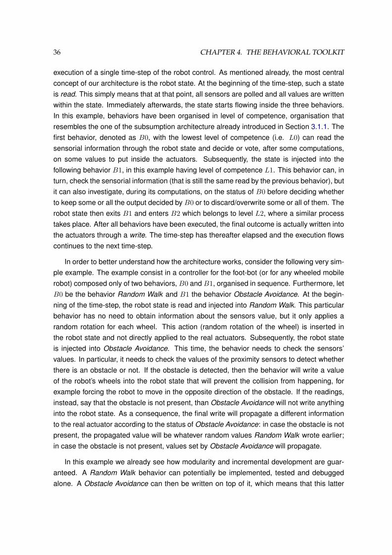
a robot state. A robot state is a wrapper around the complete sensor and actuator spaceof the robot. At each time-step, the robot state contains a photography of the values ofall the sensors at that time-step. This information is shared and is kept fixed amongst allbehavior acting at that time-step. Furthermore, it contains also a copy of all the actuators’statuses. Such an information can be modified by each behavior inside a single time-step.The order with which behaviors write into the actuators determine the final, overall outcomeof the controller.
To better structure the explanation of the architecture, we split it into two different sec-tions. In Section 4.2.1 we will depict how it is possible to combine the action of two or morebehaviors into another, higher-level behavior, under the assumption that they are executedin sequential order. Next, in Section 4.2.2, we will examine the more general case of behav-iors acting in parallel. Finally, Section 4.3 is devoted to more practical examples on how thearchitecture is implemented and how to use it in the ARGoS simulator.
4.2.1 Sequential Behaviors
Figure 4.1 depicts a schematic that represents the behavioral toolkit implementing a behaviorthat combines three other behaviors executed in sequential order. It represents the control
36 CHAPTER 4. THE BEHAVIORAL TOOLKIT
execution of a single time-step of the robot control. As mentioned already, the most centralconcept of our architecture is the robot state. At the beginning of the time-step, such a stateis read. This simply means that at that point, all sensors are polled and all values are writtenwithin the state. Immediately afterwards, the state starts flowing inside the three behaviors.In this example, behaviors have been organised in level of competence, organisation thatresembles the one of the subsumption architecture already introduced in Section 3.1.1. Thefirst behavior, denoted as B0, with the lowest level of competence (i.e. L0) can read thesensorial information through the robot state and decide or vote, after some computations,on some values to put inside the actuators. Subsequently, the state is injected into thefollowing behavior B1, in this example having level of competence L1. This behavior can, inturn, check the sensorial information (that is still the same read by the previous behavior), butit can also investigate, during its computations, on the status of B0 before deciding whetherto keep some or all the output decided by B0 or to discard/overwrite some or all of them. Therobot state then exits B1 and enters B2 which belongs to level L2, where a similar processtakes place. After all behaviors have been executed, the final outcome is actually written intothe actuators through a write. The time-step has thereafter elapsed and the execution flowscontinues to the next time-step.
In order to better understand how the architecture works, consider the following very sim-ple example. The example consist in a controller for the foot-bot (or for any wheeled mobilerobot) composed only of two behaviors, B0 and B1, organised in sequence. Furthermore, letB0 be the behavior Random Walk and B1 the behavior Obstacle Avoidance. At the begin-ning of the time-step, the robot state is read and injected into Random Walk. This particularbehavior has no need to obtain information about the sensors value, but it only applies arandom rotation for each wheel. This action (random rotation of the wheel) is inserted inthe robot state and not directly applied to the real actuators. Subsequently, the robot stateis injected into Obstacle Avoidance. This time, the behavior needs to check the sensors’values. In particular, it needs to check the values of the proximity sensors to detect whetherthere is an obstacle or not. If the obstacle is detected, then the behavior will write a valueof the robot’s wheels into the robot state that will prevent the collision from happening, forexample forcing the robot to move in the opposite direction of the obstacle. If the readings,instead, say that the obstacle is not present, than Obstacle Avoidance will not write anythinginto the robot state. As a consequence, the final write will propagate a different informationto the real actuator according to the status of Obstacle Avoidance: in case the obstacle is notpresent, the propagated value will be whatever random values Random Walk wrote earlier;in case the obstacle is not present, values set by Obstacle Avoidance will propagate.
In this example we already see how modularity and incremental development are guar-anteed. A Random Walk behavior can potentially be implemented, tested and debuggedalone. A Obstacle Avoidance can then be written on top of it, which means that this latter
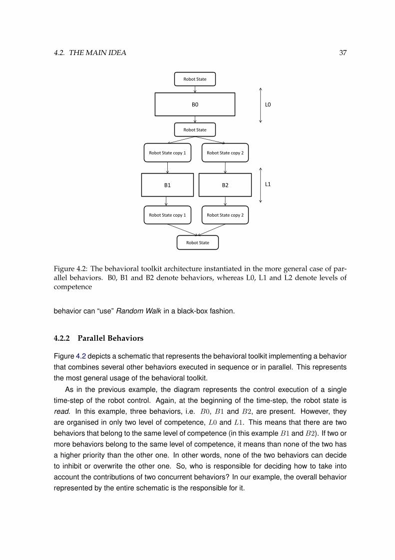
4.2. THE MAIN IDEA 37
B0
Robot State
B1
Robot State
Robot State
Robot State copy 1
B2
Robot State copy 2
Robot State copy 1 Robot State copy 2
L0
L1
Figure 4.2: The behavioral toolkit architecture instantiated in the more general case of par-allel behaviors. B0, B1 and B2 denote behaviors, whereas L0, L1 and L2 denote levels ofcompetence
behavior can “use” Random Walk in a black-box fashion.
4.2.2 Parallel Behaviors
Figure 4.2 depicts a schematic that represents the behavioral toolkit implementing a behaviorthat combines several other behaviors executed in sequence or in parallel. This representsthe most general usage of the behavioral toolkit.
As in the previous example, the diagram represents the control execution of a singletime-step of the robot control. Again, at the beginning of the time-step, the robot state isread. In this example, three behaviors, i.e. B0, B1 and B2, are present. However, theyare organised in only two level of competence, L0 and L1. This means that there are twobehaviors that belong to the same level of competence (in this example B1 and B2). If two ormore behaviors belong to the same level of competence, it means than none of the two hasa higher priority than the other one. In other words, none of the two behaviors can decideto inhibit or overwrite the other one. So, who is responsible for deciding how to take intoaccount the contributions of two concurrent behaviors? In our example, the overall behaviorrepresented by the entire schematic is the responsible for it.

38 CHAPTER 4. THE BEHAVIORAL TOOLKIT
In this example, B0 is executed at first and then, sequentially afterwards, B1 and B2 areexecuted in parallel. However, we cannot allow the “main” robot state to be injected in anyof the two behaviors, since none of the two is allowed to modify the actuators’ variables. Tosolve this issue, a simple but effective copy functionality has been provided. Before enteringany of the two behaviors, two copies of the robot state are created. Any modification toany of these copies will not affect the main robot state and hence will not influence thefinal values of the actuators’ variables. Each of the two robot state copies is injected intothe corresponding behavior. After they perform their computations, two potentially differentrobot states are returned. It is then the duty of another behavior, which can be considered acombiner behavior, to perform the computation of the final robot state, based on the individualcontributions of B1 and B2 and on other potential information computed by the combiner.
Let us now consider a practical example of two competing behaviors. Let’s suppose thetask at hand is defined as following a sequence of colored lights that determine an uniquedirection or path1. As it has been found, a cardinality of colors of 3 is sufficient to identifya direction of movement (Nouyan et al., 2008). Let the three colors be white, green andcyan (in the given sequence). We can think of having three behaviors (or a single behaviorinstantiated three times each with a different color) implementing the functionality GoToLED.These (or this) behavior will compute the direction and the distance to the closest LED ofthat specific color and write on the robot state the wheel speeds able to make the robot headtowards that LED. Moreover, each behavior can be polled and asked, at any time, what is thedirection and the distance to the led computed so far. These three behaviors are examplesof behaviors that can be executed in parallel. It is then the duty of the combiner behaviorto decide which of the three behavior’s output should be propagated in the real robot state.The combiner behavior can implement, for example, the following logic:
1. Set a current color variable to white;
2. Execute the three behaviors concurrently;
3. Apply only the output of GoToLED(current color) to the real robot state;
4. Poll the behavior GoToLED(current color) for the distance to the LED;
5. If the distance is below a certain threshold, current color=next(current color)2;
6. GOTO 2

4.3. IMPLEMENTATION IN THE SWARMANOID SIMULATOR 39
Figure 4.3: The class diagram of the behavioral toolkit inside ARGoS
4.3 Implementation in the Swarmanoid Simulator
Figure 4.3 shows the class diagram of the behavioral toolkit inside the ARGoS simulator. Fora comparison with the diagram of the control section of ARGoS without the toolkit refer toFigure 2.6.
As we can see, a behavior controller, instead of extending directly from CCI Controller,extends from a new class called CCI BehaviorController. This new class is a tem-plate class. The parameter is the CCI RobotState subtype that refers to the robot forwhich the controller is going to be implemented. Since three robot types are available in theSwarmanoid project and since sensors and actuators are different in those robots, we pro-vided three subclasses of CCI RobotState: CCI FootBotState, CCI HandBotState
and CCI EyeBotState. CCI BehaviorController contains one reference to an objectof the CCI RobotState class. It also contains a reference to a CCI Behavior object,which is the root (main) behavior of the controller. A CCI Behavior, in turn, can be com-posed of multiple other behaviors in a arbitrary way. Furthermore, it also a template class aseach behavior will be associated only to a particular robot corresponding to the chosen robotstate. Finally, a behavior extends also from the FSM class, which is an utility that allows amore modular development of components (states, transitions) inside a single behavior anda better and standardized inter-communication amongst multiple behaviors. It’s usage willbe better explained in Sections4.4.
The background colors of the class diagram are used to denote the package in which theclasses resides. The entire behavioral toolkit resides in the common package (red), whereasuser written controller go in the user package. In the yellow area we have an area denoting
1This example is an exemplification of one of the tasks that will be introduced later in Section 5.4.12where next(white)=green, next(green)=cyan and next(cyan)=white

40 CHAPTER 4. THE BEHAVIORAL TOOLKIT
1 i n t CBTFootBootSampleController : : I n i t ( const TConfigurationTree t t r e e ) {2 /∗ D i s p l a y t h e c o n f i g u r a t i o n t r e e p a s s e d t o t h i s c o n t r o l l e r ∗ /3 CExperimentConfiguration : : Pr in tConf igurat ionTree ( t t r e e ) ;4
5 / / Get t h e a r o b o t s t a t e and t h e r o o t b e h a v i o r6 m pcState = new CCI FootBotState ( GetRobot ( ) ) ;7 m pcState−>I n i t ( ) ;8 m pcRootBehavior = new CBTFootbotSampleBehavior ( ) ;9 m pcRootBehavior−>I n i t ( ) ;
10
11 return CCI Control ler : : RETURN OK;12 }13
14 void CBTFootBootSampleController : : ControlStep ( ) {15 / / C a l l t h e c o n t r o l s t e p in o f t h e i n t e r f a c e16 CCI BehaviorControl ler<CCI FootBotState > : : ControlStep ( ) ;17 }18
19 void CBTFootBootSampleController : : Destroy ( ) {20 / / Clean up in t h e r o o t b e h a v i o r21 m pcRootBehavior−>Destroy ( ) ;22
23 / / R e l e a s e memory24 delete m pcState ;25 delete m pcRootBehavior ;26 }
Figure 4.4: The code of a sample behavior controller
a repository of behavior written by all users in the project. This repository, once available,will reside still in the user package but will be shared amongst all users.
In the following sections we will explain how to write the code of a behavior controller.
4.4 Writing a Behavior Controller
Figure 4.4 shows the C++ code of a behavior controller. As a matter of fact, the code needsnot to be written by the user, as its creation is completely automated by a script calledcreate behavior controller.sh.
In the Init method, the main robot state is instantiated (lines 8-9) together with theroot behavior (lines 10-11). In the ControlStep method, the ControlStep method of thesuperclass is called. Such method’s implementation is shown in Figure 4.5. As we can see,this reflect exactly the logic explained in Section 4.2.1 in Figure 4.1: first, the state is read,then injected in the top behavior and finally applied or written. The Destroy method justcontains standard cleaning of all instantiated objects.
4.4.1 Writing a Behavior combining Sequential Behaviors
Figure 4.6 shows a simple, atomic behavior (i.e. a behavior that doesn’t use any sub-behaviors). We only report the Step function, which is the most important one. If this

4.4. WRITING A BEHAVIOR CONTROLLER 41
1 template<c l a s s TRobotState> c l a s s CCI BehaviorControl ler : public CCI Control ler {2 . . .3 /∗∗4 ∗ @ b r i e f The c o n t r o l s t e p o f a b e h a v i o r c o n t r o l l e r f i r s t r e a d s from t h e s e n s o r s5 ∗ and w r i t e s t o t h e s t a t e o b j e c t . Then , i t e x e c u t e s t h e r o o t b e h a v i o r s t e p , t h a t6 ∗ might t r i g g e r t h e s t e p o f a l l i t s sub−b e h a v i o r s , in o r d e r t o modi fy t h e r o b o t7 ∗ s t a t e . At t h e end , t h e m o d i f i e d a c t u a t o r s t a t e i s a p p l i e d us ing t h e a c t u a t o r s .8 ∗9 ∗ /
10 v i r t u a l void ControlStep ( ) {11 m pcState−>ReadState ( ) ;12 m pcRootBehavior−>Step (∗m pcState ) ;13 m pcState−>ApplyState ( ) ;14 }15 . . .16 } ;
Figure 4.5: A small subsection of the CCI BehaviorController class
1 void CBT FBObstacleAvoidance : : Step ( CCI FootBotState& cRobotState ) {2
3 double fLef tSpeed = 0 . 0 ;4 double fRightSpeed = 0 . 0 ;5
6 double readings [ CCI FootBotState : : NUM PROXIMITY SENSORS ] ;7 cRobotState . GetAllProximitySensorReadings ( readings ) ;8
9 / / h e r e comes t h e e n t i r e l o g i c which s e t s10 / / f L e f t S p e e d and f R i g h t S p e e d a p p r o p r i a t e l y11
12 cRobotState . SetFootBotWheelsAngularVelocity ( fLeftSpeed , fRightSpeed ) ;13 }
Figure 4.6: A sample, atomic behavior
1 void CBT FBRandomWalkWithObstacleAvoidance : : I n i t ( ){2 m pcRW = new CBT FBRandomWalk ( ) ;3 m pcOa = new CBT FBObstacleAvoidance ( CBT FBObstacleAvoidance : : VERSION VECTOR BASED ) ;4 }5
6 void CBT FBRandomWalkWithObstacleAvoidance : : Step ( CCI FootBotState& cRobotState ) {7 m pcRW−>Step ( cRobotState ) ;8 m pcOa−>Step ( cRobotState ) ;9 }
Figure 4.7: A sample behavior combining two other behaviors sequentially: random walkwith obstacle avoidance
behavior is indicated as the root behavior of a controller, this step function will be called bythe CCI BehaviorController Step method at line 14 of Figure 4.5. Line 7 shows anexample of how to poll the sensor readings from a CCI RobotState object, whereas line12 shows how to write something in the actuators using the same object. Whatever is putin-between these two lines is actual logic of the behavior.
Figure 4.7 shows how a non atomic behavior can be produced through the combination

42 CHAPTER 4. THE BEHAVIORAL TOOLKIT
1 void CMyController : : ControlStep ( )2 {3 i f ( ! DoubleEq ( m fObstacleAngle ,SENSOR ANGLE[ 1 2 ] ) &&4 ! DoubleEq ( m fObstacleAngle ,SENSOR ANGLE[ 4 ] ) ) {5 i f ( m fObstacleAngle > 5∗M PI/8 && m fObstacleAngle < M PI )6 TurnLeft (MEAN SPEED ) ;7 e lse i f ( m fObstacleAngle >= M PI && m fObstacleAngle < 11∗M PI/8)8 TurnRight (MEAN SPEED ) ;9 e lse RandomWalk(MEAN SPEED ) ;
10 }11 e lse RandomWalk(MEAN SPEED ) ;12 i f ( m fObstacleDistance < 7 && m bTimeStart == f a l s e ) {13 m nTime = 4 0 ; m bTimeStart= t rue ;14 }15 i f ( m bTimeStart == t rue ){16 i f ( m nTime ! = 0 ) m nTime−−;17 e lse {18 m bObstaclePresent = f a l s e ; m bTimeStart = f a l s e ;19 }20 }21 }
Figure 4.8: A classical controller (i.e. not exploiting the behavioral toolkit) performing ran-dom walk with obstacle avoidance
of two other behaviors (atomic or not). This example shares exactly the same logic of theexample described earlier in Section 4.2.1. As a matter of facts, combining Random Walkwith Obstacle Avoidance is as simple as this. The current example should be compared withFigure 4.8, which represents a more “classical” way of implementing the same logic in theARGoS simulator. In the Init method (lines 3-4), the two behavior are instantiated, and theObstacle Avoidance constructor is provided with an argument that specifies which version ofit should be used, as this behavior is parameterized (as potentially all of them).
As already explained in Section 4.2.1, the simple fact that that two Step methods arecalled in different order ensures a priority relationship between behaviors. However, thismethod of combining behaviors assumes that such a relationship is known a-priori. In caseswhere this is not true, priority can still be guaranteed, with the only constraint that behaviorwritten later will always have an higher or equal priority with respect to the one of alreadyexisting behaviors that needs to be encapsulated. In this example, the combiner behaviorcould use the robot state to write to the actuators after lines 10-11, overwriting whateverdecision random walk and obstacle avoidance have made. Later, another behavior couldinclude and use CBT FBRandomWalkWithObstacleAvoidance and decide to overridewhatever decision it makes, and so on . . .
4.4.2 Writing a Behavior combining Parallel Behaviors
Figure 4.9 shows an example combiner behavior. The code shows how to implement abehavior that enables a robot to follow a light chain. The logic behind this has already been

4.4. WRITING A BEHAVIOR CONTROLLER 43
1 i n t CBTFootbotFollowLEDChainParallel : : I n i t ( ) {2 . . .3 m unCurrentChain [ 0 ] = COLOR WHITE;4 m unCurrentChain [ 1 ] = COLOR GREEN;5 m unCurrentChain [ 2 ] = COLOR CYAN;6
7 for ( unsigned i n t i = 0 ; i < 3 ; i ++) {8 m pcFollowLEDs [ i ] = new CBTFootbotFollowCeilingLED ( m unCurrentChain [ i ] ) ;9 }
10 }11
12 void CBTFootbotFollowLEDChainParallel : : Step ( CCI FootBotState& cRobotState ) {13 / / D u p l i c a t e t h e s t a t e t h r e e t i m e s14 m p v P a r a l l e l S t a t e s [ 0 ] = m p v P a r a l l e l S t a t e s [ 1 ] = m p v P a r a l l e l S t a t e s [ 2 ] = cRobotState ;15
16 / / S t ep p a r a l l e l y in a l l t h e b e h a v i o r s17 for ( unsigned i n t i = 0 ; i < 3 ; i ++) {18 m pcFollowLEDs [ i ]−>Step ( m p v P a r a l l e l S t a t e s [ i ] ) ;19 }20
21 / / Copy b a c k in t h e main s t a t e t h e s t a t e m o d i f i e d by t h e a p p r o p r i a t e b e h a v i o r22 cRobotState = m p v P a r a l l e l S t a t e s [ m nNextColorIndex ] ;23
24 / / Check whe the r t o change t h e b e h a v i o r t h a t must be c o n s i d e r e d25 double minBlobDistance = m pcFollowLEDs [ m nNextColorIndex]−>GetDistanceToLEDColor ( ) ;26 i f ( minBlobDistance < DISTANCE THRESHOLD) {27 m nNextColorIndex = ( m nNextColorIndex + 1) % 3 ;28 }29 }
Figure 4.9: A sample behavior combining two other behaviors parallely
explained in Section 4.2.2.
Assume we have implemented a behavior called CBTFootbotFollowCeilingLED thatis instantiated three times by providing each time a different color parameter (line 10). Thecombination logic is implemented in the Step method: we first replicate the main robot statethree times (line 18); we then execute the three behaviors in parallel (line 22); we then then“combine” then by taking into account only the behavior’s output corresponding to the colorthat is currently being followed (line 26); finally, if the robot is close enough to the LED, wego to the next color (lines 29-32).
The code in Figure 4.9 is an example to show how to combine parallel behaviors. Acontroller using such behavior does not pretend to be the most efficient solution to the giventask. In this particular case, we do not need to step in all three sub-behaviors since only theoutput and the internal state of the behavior corresponding to the current color is taken intoaccount. However, a logic similar to the one shown in Figure 4.9 can be used in the moregeneral case where multiple behaviors’ output or internal state need to be checked beforemaking a decision.
In the example we note that combiner behaviors need often to access some informationabout the “status” or “internal state” of the behaviors they are combining. In the example (line29), we used a method that has the role of providing the specific information needed in this

44 CHAPTER 4. THE BEHAVIORAL TOOLKIT
1 CBTFootbotSampleBehavior : : I n i t ( ) {2 / / I n i t i a l i z i n g t h e s t a t e s3 m pcStateOne = i n i t i a l i z e S t a t e ( this , STATE ONE, ” [STATE ONE] ” ) ;4 m pcStateTwo = i n i t i a l i z e S t a t e ( this , STATE TWO, ” [STATE TWO] ” ) ;5 m pcStateThree = i n i t i a l i z e S t a t e ( this , STATE THREE , ” [STATE THREE] ” ) ;6
7 / / D e f i n e a l l t h e t r a n s i t i o n s c o n d i t i o n s8 m pcStateOne−>addTransi t ion ( ” condit ionX ” , m pcStateTwo ) ;9 m pcStateTwo−>addTransi t ion ( ” condit ionY1 ” , m pcStateThree ) ;
10 m pcStateThree−>addTransi t ion ( ” condit ionY2 ” , m pcStateTwo ) ;11
12 / / S e t i n i t i a l s t a t e13 s e t S t a r t S t a t e ( m pcStateOne ) ;14 }15
16 void CBTFootbotSampleBehavior : : Step ( CCI FootBotState& cRobotState ) {17 . . .18 i f ( GetStateID ( ) == STATE ONE){19 / / Deal wi th STATE ONE20 input ( TransitionOneToTwo ( cRobotState ) ) ;21 }22 e lse i f ( GetStateID ( ) == STATE TWO){23 / / Deal wi th STATE TWO24 input ( TransitionTwo2Three ( cRobotState ) ) ;25 }26 e lse i f ( GetStateID ( ) == STATE THREE){27 / / Deal wi th STATE THREE28 input ( TransitionTwo2Three ( cRobotState ) ) ;29 }30 }31
32 s t r i n g CBTFootbotSampleBehavior : : TransitionOneToTwo ( CCI FootBotState& cRobotStateCopy ){33 s t r i n g r e s u l t = ”” ;34 / / i f ( c o n d i t i o n s met t o change t o STATE TWO) r e s u l t = ” c o n d i t i o n X ” ;35 return r e s u l t ;36 }37
38 s t r i n g CBTFootbotSampleBehavior : : TransitionTwo2Three ( CCI FootBotState& cRobotStateCopy ){39 s t r i n g r e s u l t = ”” ;40 / / i f ( c o n d i t i o n s met t o change t o STATE THREE) r e s u l t = ” c o n d i t i o n Y 1 ” ;41 / / e l s e i f ( c o n d i t i o n s met t o change t o STATE TWO ) r e s u l t = ” c o n d i t i o n Y 2 ” ;42 return r e s u l t ;43 }
Figure 4.10: A sample template behavior showing how to use the FSM tool
case, i.e. the distance to the closest LED. In the next section, we introduce the Finite StateMachine (FSM) tool, which enables both a more modular coding of an individual behaviorand a more standardized inter-behavior communication mechanism.
4.4.3 Dealing with Finite State Machines
Behaviors can be thought as software modules that provide some sort of mapping betweenstimuli coming from the real world and robot’s actions. Such mapping can be formalizedusing a Finite State Machine (henceforth FSM) (Minsky, 1967).
FSMs are not only a useful mathematical tool to model such systems, but they can alsobe used to provide a better logical and structural organization of real code. In the behavioral

4.4. WRITING A BEHAVIOR CONTROLLER 45
Figure 4.11: The diagram of the very simple FSM implemented in Figure 4.10
toolkit, we included such a tool obtained by adapting the FSMPP library, which is freelyavailable library3 to build Deterministic Finite State Machines in C++.
Suppose we have a behavior whose corresponding FSM is the one depicted in Fig-ure 4.11. The corresponding code in the behavioral toolkit is shown in Figure 4.10.
The code has an organized structure that allows the separation amongst code pertainingto different states and between states and transitions. In the example, the three states areinitialized in the Init function (lines 3-5), where each state is associated to both an integerunique identifier and to a string, which is useful for debugging purposes. In the followingthree lines (lines 8-10), we link states through transitions. Strings such as “conditionX” arelabels that identify events that triggers transitions. The last line of the Init function is usedto specify the initial state.
In the Step method, a simple if or alternatively switch construct can be used to dealwith the different states. After dealing with each state, the input method needs to becalled: it accepts a string argument, which represents the label of a possible event that cancause a transition. Code that manages transitions can be organised in specialized methods.In the example, method TransitionOneToTwo (lines 32-36) menages unidirectional thetransition between State One and State Two, whereas method TransitionTwo2Three
(lines 38-43) menages bidirectional the transition between State Two and State Three (noticethe conventional use of “to” or “2” to distinguish between the unidirectional and bidirectionalcase).
The final example in Figure 4.4.3 shows how to use the FSM tool in order to achieve amore standardized communication between different behaviors. In the example, a combinerbehavior B3 is trying to combine two behaviors, B1 and B1, which both implements the FSMinterface. As a result, the GetStateID method can be used to query sub-behaviors abouttheir internal state (lines 4 and 7).
In this section we provided simple examples only. In the next chapter, we will describemore complex behaviors. All behaviors were are implemented using the behavioral toolkit,
3http://sourceforge.net/projects/fsmpp, under by the GPS licence

46 CHAPTER 4. THE BEHAVIORAL TOOLKIT
1 void B3 : : Step ( CCI FootBotState& cRobotState )2 {3 . . .4 i f ( m pcB1−>GetStateID ( ) == B1 : : STATE X){5 / / some l o g i c h e r e6 }7 i f ( m pcB2−>GetStateID ( ) == B2 : : STATE X){8 / / some o t h e r l o g i c h e r e9 }
10 }
Figure 4.12: A sample template behavior showing how to use the FSM tool to query behav-iors about their state
and almost all of them are organized using the FSM tool.

Chapter 5
Experiments with Modular Behaviors
In order to test its effectiveness, the behavioral toolkit has been used to develop several be-haviors for the foot-bot and for the hand-bot. In this chpater, we present several experimentsemploying these behaviors.
The chapter is organized as follows: in Section 5.1.1 we define the overall task and weshow the overall organization of the solving global behavior; subsequently, in Section 5.3and Section 5.4, we describe the two main sub-behaviors composing the global one.
5.1 Experiment Definition
The task we are tackling is the assembly and control of a composite robot called phat-bot.The phat-bot (shown in Figure 5.1) is a robot which is composed by three foot-bots assem-bled to an hand-bot. The aim of such a robot is to provide a platform able to navigate andperform manipulation at the same time, which is not possible by using foot-bots and hand-bots alone.
5.1.1 High Level Description of the Behaviors
Clearly, the task we are facing can be subdivided in two: assembly of a phat-bot and collec-tive navigation. In the following, we first introduce simple behaviors implemented on foot-botsonly. The combination of such behavior will produce the assembly behavior. Subsequently,we describe behaviors able to achieve interaction through a simple communication mech-anism amongst multiple robots, both homogeneous (footbots-footbots) and heterogeneous(footbots-handbots). The combination of these behaviors with the assembly behavior pro-duces a top behavior able to perform assembly and navigation with obstacle avoidance in anenvironment with obstacles.
The top behavior dependency structure is depicted in Figure 5.2, where a directed edgedenotes the relationship “uses” or “is composed by”. As we can see, they are organized in
47
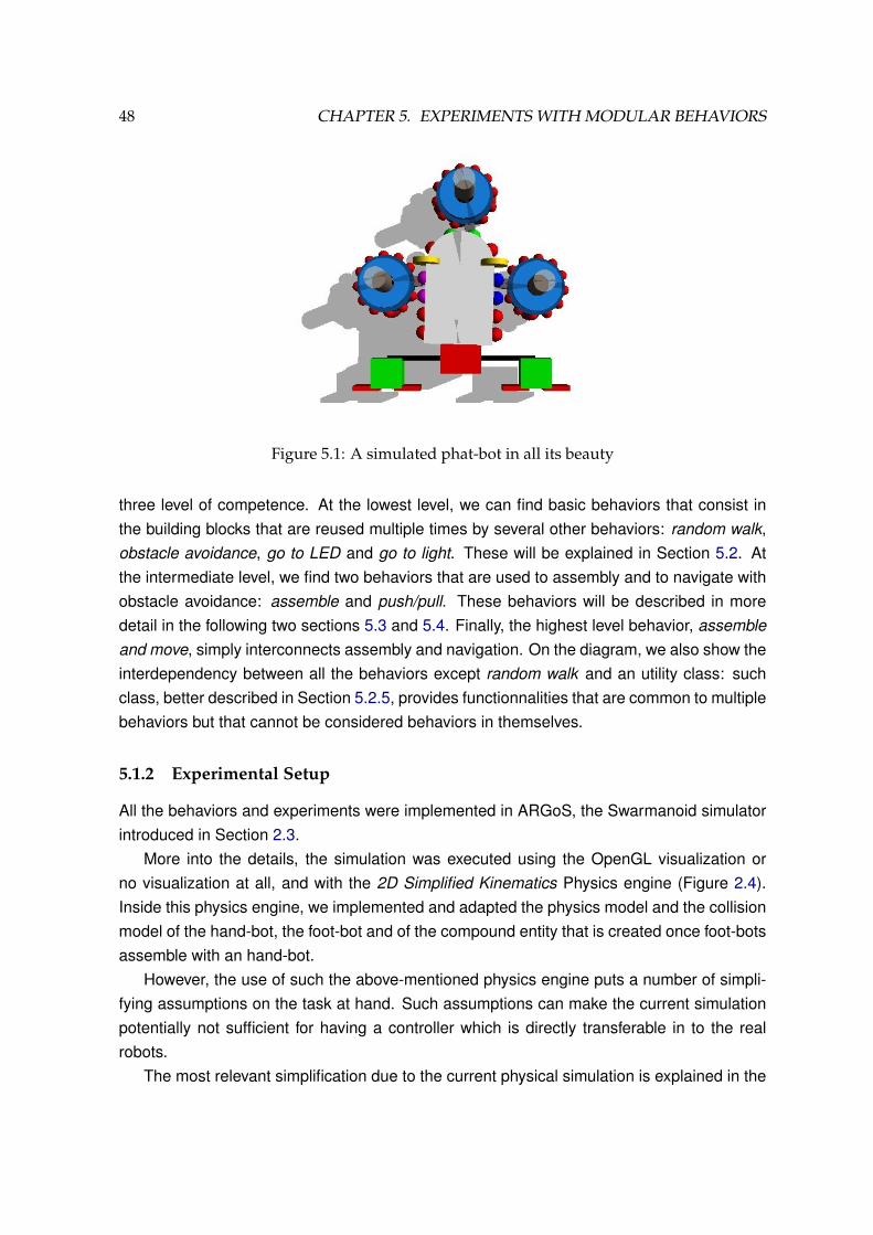
48 CHAPTER 5. EXPERIMENTS WITH MODULAR BEHAVIORS
Figure 5.1: A simulated phat-bot in all its beauty
three level of competence. At the lowest level, we can find basic behaviors that consist inthe building blocks that are reused multiple times by several other behaviors: random walk,obstacle avoidance, go to LED and go to light. These will be explained in Section 5.2. Atthe intermediate level, we find two behaviors that are used to assembly and to navigate withobstacle avoidance: assemble and push/pull. These behaviors will be described in moredetail in the following two sections 5.3 and 5.4. Finally, the highest level behavior, assembleand move, simply interconnects assembly and navigation. On the diagram, we also show theinterdependency between all the behaviors except random walk and an utility class: suchclass, better described in Section 5.2.5, provides functionnalities that are common to multiplebehaviors but that cannot be considered behaviors in themselves.
5.1.2 Experimental Setup
All the behaviors and experiments were implemented in ARGoS, the Swarmanoid simulatorintroduced in Section 2.3.
More into the details, the simulation was executed using the OpenGL visualization orno visualization at all, and with the 2D Simplified Kinematics Physics engine (Figure 2.4).Inside this physics engine, we implemented and adapted the physics model and the collisionmodel of the hand-bot, the foot-bot and of the compound entity that is created once foot-botsassemble with an hand-bot.
However, the use of such the above-mentioned physics engine puts a number of simpli-fying assumptions on the task at hand. Such assumptions can make the current simulationpotentially not sufficient for having a controller which is directly transferable in to the realrobots.
The most relevant simplification due to the current physical simulation is explained in the

5.2. BASIC BEHAVIORS 49
Figure 5.2: The overall organization of the assemble and move behavior
following. Once the phat-bot is assembled, each foot-bot rotates the wheels as they were notlinked in a compound and a vector corresponding to their individual motion is computed fromthe wheels speeds. Given all those vectors in the compound, an average vector is computedand directly applied to obtain the compound motion of the phat-bot. As a result we obtainthat, during the compound motion, the relative orientation of the wheels of each individualfoot-bot and the corresponding friction is not taken into account at all. In reality, if the wheelsare not oriented in the same direction of the phat-bot motion, their friction could potentiallyprevent the entire entity from moving or at least slow the motion down. To account for this,each foot-bot includes a turret that can be actuated in order to change the relative rotation ofthe wheels. A more complex controller which also includes such turret’s actuation is left outfor future work.
5.2 Basic Behaviors
Before explaining the logic behind the assemble behavior, we briefly introduce the basicbehaviors that were composed in order to produce it.
5.2.1 Random Walk
The random walk behavior is useful to make a mobile robot explore the environment in auniform way. It consists in applying some stochasticity to the wheels motion. Our implemen-tation is based on the following, very simple idea:
1. We generate a tuple v, tr, tt, d, where v is a random velocity scalar, tr is a random

50 CHAPTER 5. EXPERIMENTS WITH MODULAR BEHAVIORS
rotation time, tt is a random translation time and d is a random, binary rotation direction.Each of these are uniformly drawn from a different, bounded interval;
2. we rotate the robot clockwise or anti-clockwise (according to d) for tr timesteps;
3. we move the robot forward for tt timesteps at v speed;
4. go to 1;
5.2.2 Obstacle Avoidance
Our obstacle avoidance behavior can be parameterized at instantiation time, as alreadyshown in Figure 4.7. The parameter is an integer number that uniquely identify which versionof obstacle avoidance the user is willing to use. So far, we implemented two versions:
Dummy We use the proximity sensors to check whether there is a reading above a certainthreshold. If this is the case, we simply take the angle corresponding to the highestsensor reading and we turn the robot clockwise or anti-clockwise according to thisangle.
Vector-Based For each of the proximity sensor readings, we compute a vector according tothe angle reading. We then sum up these vectors, filter the resulting vector, computethe opposite vector and convert it into an appropriate wheel motion. This makes use oftwo utility functions, i.e. FilterVector and SetWheelsSpeedFromVector, whichwill be better explained in Section 5.2.5.
5.2.3 Go to LED
The go to LED is also a parametric behavior, where the parameter represent one of thepossible LED colors. This behavior is simple and it works as follows. It uses the robot’somnidirectional camera to collect all blobs of the same color as the one determined by theparameter. It then computes the distance and the direction of the closest amongst theseblobs. Finally, it converts these two numbers into a vector, it filters it since there can be noiseand it applies it to the wheels. Also this behavior uses the utility functions FilterVector
and SetWheelsSpeedFromVector, explained in Section 5.2.5.
5.2.4 Go to Light
This behavior is very similar to go to LED and even simpler. There are only two differences.The first difference is the absence of a color parameter. The second difference is due tothe sensor itself: differently from the camera, the light sensor can only return a gradientof intensity of light, that is equivalent to saying that it is not possible to distinguish clearly
5.3. PHAT-BOT ASSEMBLY 51
between two different light sources and hence, by knowing the angle corresponding to thehighest intensity, we also automatically know only the direction to the closest and/or brightestlight source. This information is then translated into the corresponding wheels motion.
5.2.5 Utility Class
The utility class does not represent a behavior in itself but just a collection of utility functions.So far, the utility functions we provided (which are mainly intended for the foot-bot) are thefollowing:
FilterVector This function can be used to filter a 2D vector using a mobile average filter. Thefiltered vector is computed as follows:
Vt = αVt +(1− α)W
Vt−1 +(1− α)W
Vt−2 + . . .+(1− α)W
Vt−W (5.1)
where Vt is the vector at time t, Vt−k is the vector delayed k steps in the past, W ∈ Nis the filtering window or memory size and α ∈ (0, 1) is a recency factor. W and α canbe changed at any time dynamically. Lower values of α (more influence of the past)and higher values of W (more memory) makes the filter stronger, and vice-versa.
SetWheelsSpeedFromVector This function is used to convert a vector into two floating pointnumber that represent the speed to apply to the wheels. This function comes in threeversions: no reverse, with reverse and reverse only. The first version computes thedifference between the robot’s heading direction and the vector direction and applies, ifnecessary, a turning speed to the wheels (whose intensity depends on the difference)in order to minimize this difference. In the with reverse version, if the difference be-tween the two angles is too high, then the robot is allowed to move backwards also.Finally, the reverse only version works as the no reverse but the minimized difference isthe one between the vector’s angle and the opposite of the robot’s heading (the robot’sback), yielding to a robot that will always move backwards.
GetProximityAngle This function assumes we know the maximum amount of proximity sen-sors installed on the robot. Given this number and and an index provided as input, thefunction can be used to compute the angle of the proximity sensor corresponding tothat index.
5.3 Phat-bot Assembly
The assemble behavior was obtained by combining the three basic behaviors random walk,obstacle avoidance and go to LED by the use of a very simple finite state machine, which

52 CHAPTER 5. EXPERIMENTS WITH MODULAR BEHAVIORS
Figure 5.3: The FSM of the of the assemble behavior
is depicted in Figure 5.3. Each state is represented with a name and with the name of thebehaviors it is using between square brackets. As we can see, it is composed by three statesonly:
Explore It combines random walk with obstacle avoidance in a sequential fashion as al-ready explained in Figure 4.6 of Section 4.4.1. Foot-bots in this state will explore theenvironment in order to search for a hand-bot.
Approach It uses the go to LED behavior parametrized with some color in order to approacha colored slot lit on the hand-bot’s LED ring while aligning to it. The colored slot can beof three different colors, as explained in the following.
Gripped This state is mainly used for communicating to an potential top behavior the factthat the foot-bot has finished assembling (refer to Figure 4.4.3 in Section 4.4.3).
The critical part of the assemble behavior is the TransitionExplore2Approachmethod,which implements the logic of the bidirectional transition between the two mentioned states.Such transition must be clever enough to allow a foot-bot to start approaching an hand-botonly when some conditions are satisfied and stop approaching it in case these conditionsare no longer satisfied. Such desired conditions are:
• The foot-bot can approach only from some predefined angles, i.e. from the back, fromthe right and from the left and not diagonally;
• The foot-bot can approach only if there is no other foot-bot approaching from the sameangle.
Futhermore, we want also each assembled foot-bot to know its role (i.e. where it assembled)in the compound structure in order to facilitate navigation later. In order to guarantee theabove properties, we defined a very simple LED color protocol. It works as shown in Fig-ure 5.4. The hand-bot will turn on its LED as shown in Figure 5.4a: blue, green and violet

5.3. PHAT-BOT ASSEMBLY 53
(a) (b)
(c) (d)
Figure 5.4: The assembly behavior: (a) The assembly protocol on the hand-bot, (b) foot-botcannot assemble since the angle is not correct, (c) foot-bot cannot assemble since anotherfoot-bot is already assembled at that slot and (d) a crowded situation where foot-bots stillmanage to assemble. Notation: dr = distance to closest red blob, dg = distance to closestgreen blob, etc . . .
colors defines connection areas or slots, whereas the red color defines areas where foot-botsare not allowed to connect. The three colors denotes the left, back and right slot, which willbe also used to determine the foot-bot role as we will see later in Section 5.4. Also, the areawhich is the closest to the gripper is lit with two red LEDs instead than one: this is to preventa foot-bot attaching too close to the hand-bot arms, which would saturate the proximity sen-sors and make the navigation task more difficult. In the TransitionExplore2Approach
method we use the following rule: if the distance to the closest red color is greater than thedistance to the closest slot we trigger the transition from explore to approach, otherwise wetrigger the transition from approach to explore. This simple rule can guarantee both of the

54 CHAPTER 5. EXPERIMENTS WITH MODULAR BEHAVIORS
above properties. In fact, as we can see from Figure 5.4b, a foot-bot that is misaligned can-not enter the approach state since it will see the red closer than any of the other slots. Onthe other hand, a foot-bot entering the approach state will also turn all its LEDs to red. In thisway, we disallow a foot-bot to enter the approach state in case another foot-bot is alreadyapproaching, since also in this case red will be seen as closer than the slot (Figure 5.4c).
The above behavior has been tested and it ensures that only three robots attaches to thehand-bot also in very critical and crowded situations like the one shown in Figure 5.4d.
The behavior can be improved in several ways. Most notably, we need to investigatehow to use less colors (ideally only two instead of four) in order to define the slot areas.Additionally, right now we only rely on random walk for search for an hand-bot and for asuitable slot. Behaviors such as go around could be useful to search fo a slot once anhand-bot has been found, in order to increase efficiency.
5.4 Phat-bot Navigation
In this section we describe the cooperative navigation strategies that we implemented onthe foot-bot and on the hand-bot in order to let it move in an environment without and withobstacles. In Section 5.4.1, we first briefly introduce the follow chain behavior, which is avariation of the behavior already explained in Sections 4.2.2 and 4.4.2 able to let a phat-botfollow a chain made of colored LEDs. Subsequently, in Section 5.4.2, we describe the pushand pull behaviors, which are used to let a phat-bot move towards a direction while avoidingobstacles.
5.4.1 Follow Chain Behavior
A sample follow chain behavior was already explained in Section 4.4.2. However, for ef-ficiency purposes, in our actual experiments we implemented a slightly different behavior.These two behaviors differ mainly in the following two key points:
• The “efficient” version does not use three go to led behaviors but just considers thedirection and the distance to the led of the color that is currently being followed;
• The version presented earlier works on an individual foot-bot without assuming its con-nection to a phat-bot. Instead, the modified version assumes the connection with thephat-bot, hence it is executed only if the foot-bot is connected to the back slot.
5.4.2 The Push and Pull Behaviors
The push and pull behaviors are very similar and share the basic idea and most of theimplementation details. The main difference between the two behaviors is that push requires

5.4. PHAT-BOT NAVIGATION 55
Figure 5.5: The FSM of the of the pull and push behaviors
the cooperation of the hand-bot whereas pull does not. The requirements on both behaviorsare the following: given a common direction of movement given by the presence of a lightsource, the foot-bot must be able to move the hand-bot towards that direction while avoidingobstacles, either by pushing or pulling.
The task is somehow challenging since the three foot-bots need to coordinate their move-ments both to move towards the common direction and to avoid obstacle. The first part of thetask has been simplified by allowing the light source to be perceived by all robots, togetherwith the assumptions related to the physics engine and explained already in Section 5.1.2.This leaves only the second part of the problem completely unsolved: how to coordinate therobots movement while doing obstacle avoidance?
We solved the above issue by using, again, a colored LEDs protocol. The basic idea isthe following: if a foot-bot sees an obstacle, it should use its LEDs to suggest to the otherfoot-bots to translate the phat-bot either left or right (we used cyan to denote right and whiteto denote left). If a foot-bot does not perceive an obstacle but perceives either a cyan or awhite color blob, it should translate the phat-bot either left or right as instructed. Additionally,if the foot-bot perceiving the cyan or white blob is the central one, it should also act as arelay by turning its LEDs to the same color too (since left and right attached foot-bot cannotperceive themselves due to the hand-bot in the middle).
The entire idea is again summarized by a very simple finite state machines, as depictedin Figure 5.5. Again, each state is characterized by a label denoting its name and a list ofbehaviors it is using between square brackets. This time, also transitions are using behav-iors, hence they are summarized as well in square brackets after the name of the transition.

56 CHAPTER 5. EXPERIMENTS WITH MODULAR BEHAVIORS
The meaning of each state and the corresponding logic can be summarized as follows:
Phototaxis No obstacles are perceived. Hence, each robot can perform the phototaxis bystepping into the go to light behavior, causing the entire phat-bot to move towards thedirection of the light. The difference between push and pull is that a different versionof the SetWheelsSpeedFromVector utility function is used, i.e. no reverse and withreverse respectively (refer to Section 5.2.5 for more details).
Avoid The obstacle has been directly perceived. Hence, if the foot-bot is attached to oneof the two sides of the hand-bot, it starts “pushing” in order to translate the phat-botaway from the obstacle, else (it is attached to the center) it doesn’t apply any motionto the wheels. Furthermore, if the foot-bot is attached to the left, it should turn LEDsinto white to tell the other foot-bots to translate the entity to the right. Vice-versa, ifattached to the right, it should turn cyan. Finally, if the foot-bot is attached to thecenter, the correct color must be determined by checking the proximity sensor’s angleat which the obstacle has been perceived together with the angle of the light (this isthe point where the two sub-behaviors go to light and obstacle avoidance are used inthis state).
Avoid Induced Left or Right The robot did not detect an obstacle but it did perceive a signalby another foot-bot which detected an obstacle. At this point, the correct course ofaction is detected by the 〈s, r〉 ∈ {left, right}2 pair, where s is the state (induced left orright) and r is the role (attached to the left or to the right). If s = r, the correct action isto move backwards, whereas it should move forward in case s 6= r. As an example, ifs = left (another foot-bot has seen an obstacle on the right of the phat-bot and hence itshould translate to left) and r = right, it should move forward. The central foot-bot has,as we already said, only the role of propagating the signal, hence it should turn cyanor white according to whether it’s in the avoid induced left or right state respectively.
Furthermore, the transitions can be explained as follows:
TransitionPhototaxis2Avoid This transition uses the obstacle avoidance behavior to checkwhether an obstacle is present or not. If the obstacle is present, the transition fromthe phototaxis state to the avoid state is triggered, otherwise the opposite transition istriggered. The obstacle avoidance behavior can be parameterized in order to specifyan activation area, i.e. which set of reading to consider and which to discard. Thisis done since each foot-bot needs to discard reading coming from the circular sectionwhich faces the hand-bot, as shown in Figure 5.6.
TransitionPhototaxis2AvoidInduced This transition uses the go to led behavior in order tocheck whether there is a cyan or white color blob in range. If this is the case, the

5.4. PHAT-BOT NAVIGATION 57
Figure 5.6: Diagram showing the range of activation of the proximity sensors in the obstacleavoidance behavior during phat-bot navigation
transition from phototaxis to avoid induced (left or right respectively) is triggered (someother foot-bot has perceived an obstacle), otherwise the opposite transition is triggered(no more obstacles are perceived, hence the foot-bot can go back to phototaxis state).
TransitionAvoidToAvoidInduced This transition is defined only in the pull behavior andin case the foot-bot is attached to the back slot. It uses the go to led behavior tounderstand whether another foot-bot has perceived an obstacle on the left or on theright. If this is the case, switching to the avoid induced state has an higher priority sinceif we do not translate the phat-bot in the correct direction it will get stuck for sure.
TransitionAvoidInducedToAvoid This transition uses the obstacle avoidance behavior todetect obstacles as in the TransitionPhototaxis2Avoid transition. This transitionis needed since the foot-bot that perceives an obstacle directly needs to react in orderto avoid getting stuck.
TransitionAvoidInducedLeft2AvoidInducedRight If a robot is in the avoid induced leftstate and perceives a white signal through the go to led behavior, it should react andchange to the avoid induced right state (vice-versa for the other case).
We can notice that the difference between the push and the pull behavior is minor. The maindifference is due to the fact that, in the push behavior, the hand-bot needs to cooperate as

58 CHAPTER 5. EXPERIMENTS WITH MODULAR BEHAVIORS
well. As said in Section 2.2.3, the hand-bot is provided with proximity sensors in each gripper.These sensors can be used to detect obstacles as well. To achieve so, we implemented avery simple behavior on the hand-bot: if the hand-bot perceives something close to its leftgripper, it turns white, whereas if it perceives an obstacle close to its right gripper it turnscyan. The behavior of the foot-bot can be kept the same, since it automatically integrates thepresence of the hand-bot due to the standardized color protocol.
In order to compare the two strategies, we ran a simple experiment that consisted in arace between phat-bots using the two strategies. Each strategy was executed for 100 runsin an environment like the one depicted in Figure 5.7a. A run is completed when the phat-bot reaches the end of the corridor (not shown on the figure). Figure 5.8 shows there isno substantial difference between the performances (number of time-steps to complete thetask) of the two behaviors, and that both exhibit few outliers showing that the phat-bot mightget stuck some times while trying to overcome some obstacles.

5.4. PHAT-BOT NAVIGATION 59
(a)
(b) (c)
Figure 5.7: The push versus the pull behavior: (a) the two behaviors competing in the sameenvironment, (b) the push avoiding an obstacle on the right and (c) pull avoiding an obstacleon the left

60 CHAPTER 5. EXPERIMENTS WITH MODULAR BEHAVIORS
Figure 5.8: Box and wisker plot comparing the time delays of push and pull behaviors, show-ing there is no substantial difference between the two. Some outliers are present in bothcases.

Chapter 6
Conclusions and Future Work
In this work, we presented an architecture that allows the development of behaviors whilerespecting software engineering principles like code re-usability, modularity, separation ofconcerns, abstraction and incremental development. We showed that the proposed archi-tecture is inherently modular: thus, it allows to combine behaviors together and to reusethem when needed. The architecture exploits the capabilities of object oriented languages,an makes it possible to write pieces of code that are more readable thanks to a standard-ized mechanism of interconnection and communication between both multiple behavior andinside a single behavior. The architecture has been validated through an experiment whichinvolved (a) assembly of a composite robot made of two different types of robot and (b)collective navigation and obstacle avoidance using this new composite robot.
We believe that this work can be extended and improved in several ways. Amongst those,we identified two main categories of improvements, which could yield us closer to the visiondream of having a complete architecture for swarm robotics.
Scripting Behaviors In Christensen et al. (2007), they proposed a scripting language calledSWARM-MORPH for the development of behaviors for robots composing the swarm-bots project (Mondada et al., 2004). Although very promising, such scripting languageis also limited since it does not allow to develop modular primitives (basic buildingblocks of the scripting language). Hence, a first interesting direction of future workswould be to integrate an extended SWARM-MORPH script into the behavioral toolkit.By having a one to one mapping between behaviors and primitives, it would be possibleto have scripting building blocks that are no longer primitives but composite elementscomposed of different primitive or non-primitive elements.
Adaptive Behaviors A further step to go towards an architecture for swarm robotics is to ex-tend the current architecture in a way to include adaptability. There are many possibleways to achieve this, which include:
61
62 CHAPTER 6. CONCLUSIONS AND FUTURE WORK
• Including the response threshold model (Granovetter, 1978; Bonabeau et al.,1997) into the FSM (Section 4.4.3) together with a mechanism to acquire thesocial stimulus from the local (both social and non-social) environment;
• Develop a mechanism for the auto-composition of behaviors inside an individualrobots. This could be done, for example, by using evolutionary techniques (To-gelius, 2004; Ashlock, 2006).
• Use more advanced optimization and learning techniques to guarantee moreadaptive behaviors. Examples would be particle swarm optimization (Kennedyand Eberhart., 2001) or policy search reinforcement learning techniques (Peshkin,2002).
Going towards an architecture for swarm robotics that allows the development of swarm-levelcontrollers while observing software engineering principles is a very challenging goal. Thetwo main difficulties are represented by: the high heterogenuity and dynamicity of both hard-ware and software solutions available to robotics; the absence of a predetermined recipes totranslate individual-level behaviors to global-level behaviors. We believe that, in the presentwork, we developed and applied some general principles that can be used to tackle, at leastpartially, the first of these two issues. Extensions of the proposed work that can also tacklethe second issue are very interesting topics for future works.

Bibliography
Abraham, A., Grosan, C., and Ramos, V., editors (2006). Swarm Intelligence in Data Mining.Springer, Berlin / Heidelberg.
Alami, R., Chatila, R., Fleury, S., Ghallab, M., and Ingrand, F. (1998). An architecture forautonomy. International Journal of Robotics Research, 17(4):315–337.
Arkin, R. (1989). Motor schema-based mobile robot navigation. International Journal ofRobotics Research, 8(4):92–112.
Arkin, R. (1998). Behavior-Based Robotics. MIT Press, Cambridge.
Ashlock, D. (2006). Evolving Finite State Automata, chapter 6, pages 143–166. EvolutionaryComputation for Modeling and Optimization. Springer, New York.
Ben-Jacob, E., Cohen, I., and Levine, H. (2000). Cooperative self-organization of microor-ganisms. Advance in physics, 49(4):395–554.
Beni, G. (2004). From swarm intelligence to swarm robotics. In Proceedings of the Workshopon Swarm Robotics, 8th International Conference on Simulation of Adaptive Behavior, LosAngeles, CA. Springer.
Beni, G. and Wang, J. (1989). Swarm intelligence in cellular robotic systems. In Proceed-ings of the NATO Advanced Workshop on Robots and Biological Systems, Tuscany, Italy.Springer.
Bonabeau, E., Dorigo, M., and Theraulaz, G. (1999). Swarm Intelligence: From Natural toArtificial Systems. Oxford University Press, New York.
Bonabeau, E., Sobkowski, A., Theraulaz, G., and Deneubourg, J.-L. (1997). Adaptive taskallocation inspired by a model of division of labor in social insects. In Biocomputing andemergent computation: Proc. of BCEC97, pages 36–45. World Scientific Press.
Bonasso, R. (1991). Integrating reaction plans and layered competences through syn-chronous control. In Proc. of the International Joint Conference on Artificial Intelligence.
63
64 BIBLIOGRAPHY
Brooks, R. (1986). A robust layered control system for a mobile robot. IEEE Journal ofRobotics and Automation, 2(1):14–23.
Brooks, R. (1990). Elephants don’t play chess. IEEE Journal of Robotics and Automation,6:3–15.
Caro, G. D. and Dorigo, M. (1998). Antnet: Distributed stigmergetic control for communica-tions networks. Journal of Artificial Intelligence Research, 9:317–365.
Christensen, A., O’Grady, R., Birattari, M., and Dorigo, M. (2008). Fault detection in au-tonomous robots based on fault injection and learning. Autonomous Robots, 24(1):49–67.
Christensen, A., O’Grady, R., and Dorigo, M. (2007). Morphology control in a multirobotsystem. IEEE Robotics Automation Magazine, 11(6):732–742.
Crespi, V., Galstyan, A., and Lerman, K. (2008). Comparative analysis of top-down andbottom-up methodologies for multi-agent systems. Autonomous Robots, 24(3):303–313.
Detrain, C. and Deneubourg, J.-L. (2006). Self-organized structures in a superorganism: doants “behave” like molecules? Physics of Life Reviews, 3(3):162–187.
Dorigo, M. and Sahin, E. (2004). Guest editorial. special issue: Swarm robotics. AutonomousRobots, 17:111–113.
Dorigo, M. and Stutzle, T. (2004). Ant Colony Optimization. MIT Press, Cambridge, MA.
Dorigo, M., Trianni, V., Sahin, E., Groß, R., Labella, T. H., Baldassarre, G., Nolfi, S.,Deneubourg, J.-L., Mondada, F., Floreano, D., and Gambardella, L. M. (2004). Evolvingself-organizing behaviors for a swarm-bot. Autonomous Robots, 17(2–3):223–245.
Espiau, B., Kapellos, K., and Jourdan, M. (1995). Formal verification in robotics: Why andhow? In in The International Foundation for Robotics Research, editor, The SeventhInternational Symposium of Robotics Research, pages 20–1. Press.
Estlin, T., Gaines, D., Chouinard, C., fisher, F., no, R. C., Judd, M., Anderson, R., and Nesnas,I. (2005). Enabling autonomous rover science through dynamic planning and scheduling.In Proc. of the IEEE Aerospace Conference (Big Sky), pages 385–396, Piscataway. IEEEPress.
Frigg, R. and Hartmann, S. (2006). Models in science. In Zalta, E. N., editor, The StanfordEncyclopedia of Philosophy.
G. Butler, A. Gantchev, P. G. (2001). Object-oriented design of the subsumption architecture.Software: Practice and Experience, 31(9):911–923.

BIBLIOGRAPHY 65
Gat, E. (1992). Integrating planning and reacting in a heterogeneous asynchronous archi-tecture for controlling real-world mobile robots. In Proc. of the National Conference onArtificial Intelligence (AAAI), volume 2, pages 70–74, New York, NY, USA. ACM.
Gautrais, J., Michelena, P., Sibbald, A., Bon, R., and Deneubourg, J.-L. (2007). Allelomimeticsynchronisation in merino sheep. Animal Behaviour, 74:1443–1454.
Gerkey, B. and Mataric, M. (2004). A formal analysis and taxonomy of task allocation inmulti-robot systems. International Journal of Robotics Research, 23(9):939–954.
Granovetter, M. (1978). Threshold models of collective behavior. American Journal of Soci-ology, 83(6):1420–1443.
Groß R. and Dorigo, M. (2007). Fifty years of self-assembly experimentation. In Shen, W.-M.,Lipson, H., Stoy, K., , and Yim, M., editors, Proc. of the Workshop on Self-ReconfigurableRobots/Systems and Applications, Marina del Rey, CA. USC Information Science Institute.
Groß R. and Dorigo, M. (2008). Evolution of solitary and group transport behaviors forautonomous robots capable of self-assembling. Adaptive Behavior, 16(5):285–305.
Grunbaum, D., Viscido, S., and Parrish, J. K. (2004). Extracting interactive control algorithmsfrom group dynamics of schooling fish. Lecture Notes in Control and Information Sciences,309:103–117.
Jacobi, N. (1997). Half-baked, ad-hoc and noisy: Minimal simulations for evolutionaryrobotics. In Husbands, P. and Harvey, I., editors, Proceedings of the Fourth EuropeanConference on Artificial Life: ECAL97, pages 348–357. MIT Press, Cambridge, MA, USA.
Kennedy, J. and Eberhart., R. (2001). Swarm Intelligence. Morgan Kaufmann.
Kortenkamp, D., Bonasso, R., and Murphy, R. (1998). Artificial Intelligence and MobileRobots. AAAI Press/The MIT Press, Cambridge.
Lerman, K. and Galstyan, A. (2002). Two paradigms for the design of artificial collectives. InFirst Annual workshop on Collectives and Design of Complex Systems, CA. NASA-Ames.
Lerman, K., Martinoli, A., and Galstyan, A. (2005). A review of probabilistic macroscopicmodels for swarm robotic systems. Swarm Robotics Workshop: State-of-the-art Survey,LNCS 3342, pages 143–152.
Liu, W., Winfield, A., Sa, J., Chen, J., and Dou, L. (2007). Towards energy optimization:Emergent task allocation in a swarm of foraging robots. Adaptive Behavior - Animals,Animats, Software Agents, Robots, Adaptive Systems, 15(3):289–305.

66 BIBLIOGRAPHY
Mataric, M. (1992). Minimizing complexity in controlling a mobile robot population. In IEEEInternational Conference on Robotics and Automation, pages 830–835, Piscataway. IEEEPress.
Minsky, M. (1967). Computation: Finite and Infinite Machines. Prentice-Hall, New Jersey,USA.
Mondada, F., Pettinaro, G. C., Guignard, A., Kwee, I. W., Floreano, D., Deneubourg, J.-L.,Nolfi, S., Gambardella, L. M., and Dorigo, M. (2004). Swarm-bot: A new distributed roboticconcept. Autonomous Robots, 17(2–3):193–221.
Murphy, R. (2000). Introduction to AI Robotics. MIT Press, Cambridge.
Musliner, D., Durfee, E., and Shin, K. (1995). World modeling for dynamic construction ofreal-time control plans. Artificial Intelligence, 74(1):83–127.
Nilsson, N. (1969). A mobile automaton: An application of ai techniques. In Proc. of the FirstInternational Joint Conference on Artificial Intelligence, pages 509–520. Morgan Kauf-mann Publishers, San Francisco, CA.
Nouyan, S., Campo, A., and Dorigo, M. (2008). Path formation in a robot swarm. self-organized strategies to find your way home. Swarm Intelligence, 2(1). In press.
Parker, L. (1997). L-ALLIANCE: Task-oriented multi-robot learning in behavior-based sys-tems. Journal of Advanced Robotics, Special Issue on Selected Papers from IROS ’96,11(4):305–322.
Parker, L. (1998). ALLIANCE: An architecture for fault tolerant multirobot cooperation. IEEETransactions on Robotics and Automation, 14(2):220–240.
Parker, L. and Tang, F. (2006). Building multi-robot coalitions through automated task solutionsynthesis. Proceedings of the IEEE, special issue on Multi-Robot Systems, 94(7):1289–1305.
Peshkin, L. (2002). Reinforcement learning by policy search. PhD thesis, Providence, RI.Adviser: L. Kaelbling.
Pinciroli, C. (2006). Object retrieval by a swarm of ground based robots driven by aerialrobots. Diplome d’Etudes Approfondies en Sciences Appliquees thesis, IRIDIA, UniversiteLibre de Bruxelles, Belgium.
Reynolds, C. W. (1987). Flocks, herds, and schools: A distributed behavioral model. Com-puter Graphics, 21(4):25–34.

BIBLIOGRAPHY 67
Saridis, G. (1995). Architectures for intelligent controls. In Bupta, S., editor, Intelligent ControlSystems: Theory and Applications, Piscataway. IEEE Press.
Siciliano, B. and Khatib, O., editors (2008). Springer Handbook of Robotics. Springer, Berlin/ Heidelberg.
Siegwart, R. and Nourbakhsh, I. (2004). Introduction to Autonomous Mobile Robots. MITPress, Cambridge.
Soysal, O. and Sahin, E. (2005). Probabilistic aggregation strategies in swarm robotic sys-tems. In Proc. of the IEEE Swarm Intelligence Symposium, Pasadena, CA.
Sperati, V., Trianni, V., and Nolfi, S. (2008). Evolving coordinated group behaviours throughmaximization of mean mutual information. Swarm Intelligence, 2:73–95.
Tang, F. and Parker, L. (2005a). Asymtre: Automated synthesis of multi-robot task solu-tions through software reconfiguration. In IEEE International Conference on Robotics andAutomation, pages 1513–1520.
Tang, F. and Parker, L. (2005b). Distributed multi-robot coalitions through ASyMTRe-D. InIEEE International Conference on Intelligent Robots and Systems, Edmonton, Canada.
Togelius, J. (2004). Evolution of a subsumption architecture neurocontroller. Journal ofIntelligent and Fuzzy Systems, 15:2004.
Turgut, A., Celikkanat, H., Gokce, F., and Sahin, E. (2008). Self-organized flocking with amobile robot swarm. In AAMAS ’08: Proceedings of the 7th international joint conferenceon Autonomous agents and multiagent systems, pages 39–46, Richland, SC. InternationalFoundation for Autonomous Agents and Multiagent Systems.
Volpe, R., Nesnas, I., Estlin, T., Mutz, D., Petras, R., and Das, H. (2001). The CLARAtyarchitecture for robotic autonomy. In Proc. of the IEEE Aerospace Conference (Big Sky),pages 121–132, Piscataway. IEEE Press.