universitÀ di pisa electromagnetic radiations and bi l i
TRANSCRIPT

UNIVERSITÀ DI PISA
Electromagnetic RadiationsElectromagnetic Radiationsd Bi l i l I id Bi l i l I iand Biological Interactionsand Biological Interactions
“Laurea Magistrale” in “Laurea Magistrale” in BiomedicalBiomedical EngineeringEngineeringFirst First semestersemester (6 (6 creditscredits, 60 , 60 hourshours), ), academicacademic yearyear 2011/122011/12
Prof. Paolo Prof. Paolo NepaNepa
Wave Reflection and TransmissionWave Reflection and Transmission
[email protected]@iet.unipi.it
1
EditedEdited byby Dr. Dr. AndaAnda GuraliucGuraliuc18/10/2011
Lecture ContentLecture Content
Plane Wave Reflection and Transmission
• Reflection and transmission coefficients (at normal Incidence, single interface)• Stationary wave• Transmitted power density• Special cases: Dielectric‐Conductor, Dielectric‐PEC,
218/10/2011

ProblemProblem• Two different homogeneous media separated by a planar boundary located at S.• A monochromatic plane wave is impinging upon the interface S at normal incidence (assume z as• A monochromatic plane wave is impinging upon the interface S at normal incidence (assume z asdirection of propagation).• The incident wave is linearly polarized (assume electric field direction along x axis).• Medium “2” extends to infinity.
PlanarPlanar Interface
x,ε µ ε µ
1 2
Transmitted wave
Incident wave1 1,ε µ
2 2,ε µ
S z
Reflected wave
S
Due to symmetry of the problem, reflected and transmitted waves will propagate along a directionperpendicular to the interface and will exhibit the same polarization as the incident wave.
3
p p f p
18/10/2011

ApplicationsApplications
• EM wave radiated by a UMTS/GSM base station and transmitted inside a buildingEM wave radiated by a UMTS/GSM base station and transmitted inside a building• EM wave radiated by a satellite/airplane: reflection and transmission at the ground surface• EM penetration in a human body illuminated by an external antenna• Ionospheric propagation at HF frequencies• etcetc.
The radius of curvature of the boundary at the reflection point must be large w.r.t. the radiationwavelength: it implies that the boundary can be approximated by a planar interfacewavelength: it implies that the boundary can be approximated by a planar interface.
The distance of the source (antenna) from the reflection point must be large w.r.t. the radiationwavelength and antenna size (reflection point in the antenna far‐field region): it implies that theincident spherical wave can be locally approximated by a plane wave
4
incident spherical wave can be locally approximated by a plane wave.
18/10/2011

E and H field expressionsE and H field expressionsPlanar
fTotal field in medium 1(incident wave + reflected wave):
iEii
Interfacex
Transmitted wave
1 1,ε µ2 2,ε µ
1 2
1 1
1 0 0( ) jk z jk zi r
x xE z E e i E e i− += +1 10 0
1 ( )i r
jk z jk z
y y
E EH z e i e iζ ζ
− += −
iH •ii
rE
Transmitted waveIncident wave
Reflected wave
StE
tH
ti•
1
1 1
( ) y yζ ζ
Field in medium 2 (transmitted wave):
rH×
ri zy •
1,2
1,2
1,2
µζ
ε=• Characteristic impedance
• Propagation constant k ω ε µ=
2
2 0( ) jk zt
xE z E e i−=
20( )t
jk zEH z e i−= • Propagation constant 1,2 1,2 1,2k ω ε µ=
The complex amplitude of the incident plane wave is assumed known (it is due to a transmitting
2
2
( ) yH z e iζ
=
518/10/2011
antenna far away from the planar interface).

Th t ti l t f th l t i d
Boundary conditions Boundary conditions
iThe tangential components of the electric andmagnetic fields must be continuous at any pointon the interface (no free charges or currents existat the boundary).
1 2
1 2
n n
n n
i E i Ei H i H× = ×× = ×
ni2
2( ) jk ztE z E e i−=1 1( ) jk z jk zi rE z E e i E e i− += +
1
2 0( ) xE z E e i=
202( )
tjk z
y
EH z e iζ
−=
1 0 0( ) x xE z E e i E e i= +
1 10 01( )
i rjk z jk z
y y
E EH z e i e iζ ζ
− += −
i tE E E
2ζ1 1ζ ζ
1 20 0
1 20 0
z zz z
z zz z
i E i E
i H i H− +
− +
= =
= =
× = ×
× = ×
0 0 0
0 0 0
i r t
i r t
E E EE E Eζ ζ ζ
+ =
− =0 0
0 0
x xz z
y y
E E
H H− +
− +
= ==
=
6
1 1 2ζ ζ ζ
18/10/2011
0 0y yz z += =

Reflection and transmission coefficientsReflection and transmission coefficientsPlanar
Interface2 1
0 0
2
2 i tE Eζ ζζ+
=
2 12 r tE Eζ ζ−
0 0 0
1
i r t
i r t
E E E
E E Eζ+ =
− =
Interfacex
Incident wave1 1,ε µ
2 2,ε µ
1 2
fl i ffi i
2 10 0
2
2 r tE Eζ ζζ
=0 0 0
2
E E Eζ
zTransmitted wave
Reflected wave
S
0 2 10 0
0 2 1
( 0) ,( 0)
r rr ix
i i
x
E z E E EE z E
ζ ζζ ζ
= −= = = =
= +Γ Γ
Reflection coefficient
1Γ ≤
Reflected wave
0 2 1( )
xζ ζ
Transmission coefficient
1 τ+ =Γ0 2
0 0
0 1 2
( 0) 2 ,( 0)
t tt ix
i i
x
E z E E EE z E
ζτ τζ ζ
== = = =
= +
1 τ+ Γ
718/10/2011

E and H field expressions (linear polarization)E and H field expressions (linear polarization)
lPlanar Interface
x,ε µ ,ε µ
1 22 1
2 1
/ 1/ 1
ζ ζζ ζ
−=
+Γ
2 1
2 1
2 // 1ζ ζτ
ζ ζ=
+z
Transmitted wave
Incident wave1 1,ε µ
2 2,ε µ
S
Reflected wave
2( ) jk ziE z E e iτ −=
Field in medium 2:
1 12( ) [1 ]jk z j k ziE z E e e i− += + Γ
Total field in medium 1:
i 2 0( ) xE z E e iτ=
2
2 0
2
( ) jk zi
yH z E e iτζ
−=
1 0( ) [1 ] xE z E e e i= + Γ
1 1201
1
( ) [1 ]i
jk z j k z
y
EH z e e iζ
− += − Γ
0 0
r iE E= Γ
0 0
t iE Eτ=
8
2ζ1
18/10/2011
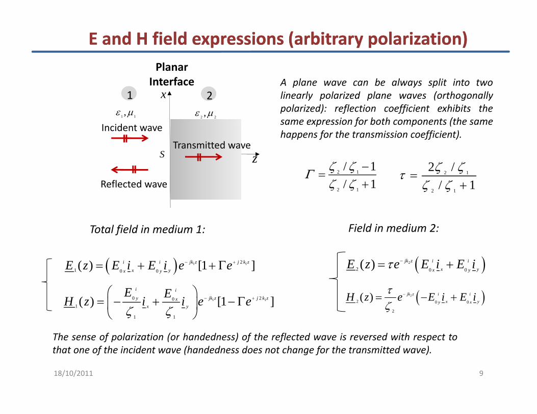
E and H field expressions (arbitrary polarization)E and H field expressions (arbitrary polarization)Planar
Interfacex
Incident wave1 1,ε µ
2 2,ε µ
1 2A plane wave can be always split into twolinearly polarized plane waves (orthogonallypolarized): reflection coefficient exhibits thesame expression for both components (the same
zTransmitted wave
Incident wave
R fl d
S
happens for the transmission coefficient).
2 12 /
/ 1ζ ζτ
ζ ζ=2 1/ 1
/ 1ζ ζζ ζ
−=Γ
Field in medium 2:Total field in medium 1:
Reflected wave2 1
/ 1ζ ζ +2 1/ 1ζ ζ +
( )2
2 0 0( ) jk z i i
x yx yE z e E i E iτ −= +( ) 1 12
1 0 0( ) [1 ]jk z j k zi i
x yx yE z E i E i e e− += + + Γ
⎛ ⎞
f
( )2
2 0 0
2
( ) jk z i i
x yy xH z e E i E iτ
ζ−= − +1 120 0
1
1 1
( ) [1 ]i i
jk z j k zy xx y
E EH z i i e eζ ζ
− +⎛ ⎞
= − + − Γ⎜ ⎟⎝ ⎠
The sense of polarization (or handedness) of the reflected wave is reversed with respect to
918/10/2011
The sense of polarization (or handedness) of the reflected wave is reversed with respect tothat one of the incident wave (handedness does not change for the transmitted wave).

Standing wave pattern (medium 1: lossless)Standing wave pattern (medium 1: lossless)
1 1 1 1k realβ ω ε µ= = = 1 1 1/ realζ µ ε= =
1 12 /λ π β=
( ) 12
1 0 1 j ziE z E e βΓ= +
( ) ( )1 11 2 4 /21 1 1j z j zj ze e eφ β φ π λβΓ Γ Γ+ ++ = + = +
( ) 12
1 0 1/ 1 j ziH z E e βζ Γ= −
je φΓ Γ= 1 1 1e e eΓ Γ Γ+ = + = +eΓ Γ=
Simultaneous presence of incident and reflected waves gives rise to a standing wave pattern. Notethat a standing wave exist only in medium 1. The magnitude of the electric (magnetic) field inmedium 1 can be analyzed to determine the locations of the maximum and minimum values of the
( )121 1j ze φ βΓ Γ++ ≤ +
medium 1 can be analyzed to determine the locations of the maximum and minimum values of theelectric (magnetic) field standing wave pattern. The standing wave pattern exhibits a repetitionperiod of half a wavelength.
12 2 ,0 1 2
z nφ β π+ =
12j ze βΓ121 j ze βΓ+
Im
1 0max(1 ),iE E Γ= +
12
0, 1, 2,...j z
ne βΓ Γ= − −
= +12
max1 j ze βΓ+
Re1
10
max
1 0 1min/ (1 )iH E ζ Γ= −
18/10/2011

k realβ ω ε µ= = = / realζ µ ε= =2 /λ π β=
Standing wave pattern (medium 1: lossless)Standing wave pattern (medium 1: lossless)
( ) 12
1 01 j ziE z E e βΓ= + ( ) 12
1 0 1/ 1 j ziH z E e βζ Γ= −
1 1 1 1k realβ ω ε µ
1 1 1/ realζ µ ε
1 12 /λ π β=
( )121 1 j ze φ βΓ Γ +− ≤ +
( ) ( )1 11 2 4 /21 1 1j z j zj ze e eφ β φ π λβΓ Γ Γ+ ++ = + = +je φΓ Γ=
1 1 eΓ Γ≤ +
12 2 ,0 1 2
z nφ β π π+ = −12
min1 j ze βΓ+
Im
112
0, 1, 2,...j z
ne βΓ Γ= − −
= −
1 0 (1 ),iE E Γ= −
min
12j ze βΓRe
1
1 0min
1 0 1max
( ),
/ (1 )iH E ζ Γ= +
The spatial distance between the location of a field maximum and the location of the closest field
121 j ze βΓ+
1118/10/2011
minimum is equal to a quarter of wavelength.

Standing wave pattern (lossless media)Standing wave pattern (lossless media)
2 1ζ ζ> ( )0 real and positiveΓ >
2 1/ 1ζ ζ −Γ
( ) 12
1 0 1 j ziE z E e βΓ= +
( ) 12
1 0 1/ 1 j ziH z E e βζ Γ= −
( )2 0
iE z E τ=
( )1 0 2/iH z E τ ζ=
2 1
2 1/ 1ζ ζζ ζ
=+
Γ
( )1 0 1ζ ( )1 0 2
ζ
0/ iE E1 Γ+
2 1ζ ζ>
0.5Γ =0 1
/ /iH E ζ
1 Γ−z
12
max1 1j ze βΓ Γ+ = + when
12 ( ) (2 ),z nβ π− = 12
min1 1j ze βΓ Γ+ = − when
12 ( ) (2 1) ,z nβ π− = +
max 1
0,1,2,...n =1
1 1(2 ) / 2
n nz nπ π λβ π λ
= − = − = −
min
0,1,2,...n =1
1
(2 1) (2 1)2(2 / ) 4
nz nπ λπ λ+
= − = − +
1218/10/2011
1 0 1 0 1min max(1 ), / (1 )i iE E H EΓ ζ Γ= − = +
1 0 1 0 1max min(1 ), / (1 )i iE E H EΓ ζ Γ= + = −
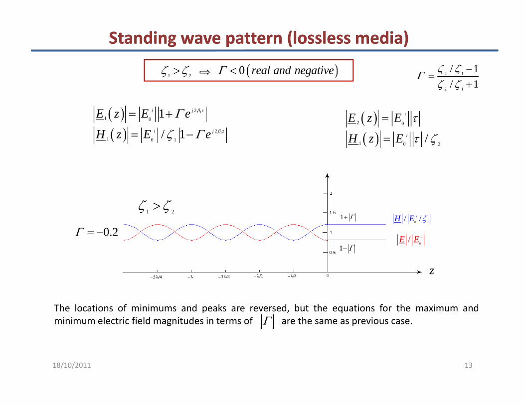
1 2ζ ζ> ( )0 real and negativeΓ <
Standing wave pattern (lossless media)Standing wave pattern (lossless media)
2 1/ 1ζ ζ −Γ1 2ζ ζ ( )g
( ) 12
1 0 1 j ziE z E e βΓ= +
2 1
2 1/ 1ζ ζ=
+Γ
( )2 0
iE z E τ=( ) 12
1 0 1/ 1 j ziH z E e βζ Γ= −
( )( )1 0 2
/iH z E τ ζ=
0 2Γ0 1/ /iH E ζ1 Γ+
1 2ζ ζ>
0.2Γ = −0
/ iE E1 Γ−
z
The locations of minimums and peaks are reversed, but the equations for the maximum andminimum electric field magnitudes in terms of are the same as previous case.Γ
1318/10/2011

DielectricDielectric‐‐conductor: medium 2 with lossesconductor: medium 2 with losses
• characteristic impedance
0 02
01eff
rj
µ µζε σε ε
ωε ε
= =⎛ ⎞−⎜ ⎟
⎝ ⎠
Planar Interface
xε µ ε
1 2
• propagation constant0 rωε ε⎝ ⎠
2 0 0 0 2 2
0
1eff rk j jσω µ ε ω ε ε µ β αωε ε
⎛ ⎞= = − = −⎜ ⎟
⎝ ⎠ zTransmitted wave
Incident wave1 1,ε µ
0, ,ε µ µ σ=
S
Filed in medium 2 (transmitted wave):
0 r⎝ ⎠
Reflected wave
2 2 2
2 0 0
jk z z j zt t
x xE E e i E e e iα β− − −= =
2 2 20 0
t tjk z z j zE EH e i e e iα β− − −= =
2 2
2 0
z j zi
xE E e e iα βτ − −=
i
22ζτζ ζ
=2
2 2
y yH e i e e iζ ζ
= =2 20
2
2
iz j z
y
EH e e iα βτζ
− −= 1 2ζ ζ+
1418/10/2011
2 2
2 ( 0) z j z
xJ E J z e e iα βσ − −= = = The majority of current exists within a few skin depthsof the surface.

Standing wave pattern (medium 2: Standing wave pattern (medium 2: lossylossy))
2 1/ 1ζ ζ −=Γ2 2 2
k jβ α= − R jXζ = −
2is complexζ is complexΓ
2 1/ 1ζ ζ=
+Γ2 2 2
jβ2
R jXζ =
( ) 12
1 0 1 j ziE z E e βΓ= +
( ) 12/ 1 j ziH z E e βζ Γ= −
( ) 2
2 0
ziE z E e ατ −=
( ) 2/ ziH z E e αζ τ −=( )1 0 1/ 1H z E eζ Γ= ( )1 0 2
/H z E eζ τ=
1 Γ+0
/ iE E 0 1/ /iH E ζ
0.8Γ =
1 Γ− z
1518/10/2011

Standing Wave RatioStanding Wave Ratio
The standing wave ratio, SWR, is defined as the ratio of the maximum electric field magnitude to theminimum electric field magnitude:
1 max1E
s SWRΓ+
= = =1sΓ −
=1 min
1s SWR
E Γ− 1sΓ
+
1 SWR≤ ≤ ∞
0no reflectionΓ = 1
total reflectionΓ =
1618/10/2011

Standing Wave PatternStanding Wave Pattern
Standing Wave Pattern Animation (SWRStanding Wave Pattern Animation (SWR))
http://http://www.youtube.com/watch?v=s5MBno0PZjEwww.youtube.com/watch?v=s5MBno0PZjE
http://www.youtube.com/watch?v=z8ya4LqG1CQhttp://www.youtube.com/watch?v=z8ya4LqG1CQ
1718/10/2011

0jkzE E e−=
1
Note: Note: PoyntingPoynting VectorVector
0 0
1jkz jkz
zH H e i E eζ
− −= = ×
&k j µβ α ζε
= − =
( ) ** *
0 0*
1 12 2
jkz jk z
zS E H E i E e eζ
−= × = × ×
( ) ( ) ( )A B C B A C C A B× × = ⋅ ⋅ − ⋅ ⋅ 2 20
1 zS E e iα−=ε0 0zi E⋅ =
2*
0 0 0E E E⋅ =
0*2 zζ
In a lossless medium (non dissipative):
2 2 2
0 0 0
1 1 1,z zS E i Si S E Hζ= = = =
( p )• has the same direction as the wave propagation• with S real and constant with respect to zS
zS Si=
( )22 2
0 0 0
1 1z zx yS E i E E i
ζ ζ= = +0 0 0,
2 2 2z z ζζ ζ
In a medium with no losses and an arbitrary propagation direction:2 2
0 0
1 12 2
S E i H i Siζζ
= = =I l di
( )0 0 02 2z zx yζ ζ
ζIn a lossy medium:• has the same direction as the wave propagation• with S having both a real and an imaginary part• S decreases as
SzS Si=
2 ze α−
⎧ ⎫
2 20*
12
z
zS E e iα
ζ−=
⎧ ⎫
18/10/2011 18
2 20*
1 1Re Re2
z
zS E e iα
ζ−⎧ ⎫
= ⎨ ⎬⎩ ⎭
2 22 * 20 0*
1 1 1( ) Re Re2 2
z zS z E e H eα αζζ
− −⎧ ⎫= =⎨ ⎬
⎩ ⎭

Note: Note: PoyntingPoynting VectorVector
[ ]i j z r j zE E e E e iβ β− += +[ ]0 0 xE E e E e i= +
0 0
i rj z j z
y
E EH e e iβ β
ζ ζ− +⎡ ⎤
= −⎢ ⎥⎣ ⎦ζ ζ⎣ ⎦
( )( ) ( )( )* *2 2
* 0 0 0 00 0 2 21 12 2
i r r ii r
j z j z
z
E E E EE ES E H e e iβ β
ζ ζ ζ ζ−
⎡ ⎤= × = − − +⎢ ⎥
⎢ ⎥2 2 zζ ζ ζ ζ⎢ ⎥⎢ ⎥⎣ ⎦
( )( ) ( ) ( )** *2 2
0 0 0 0
i r j z i r j zE E e E E eβ β− ⎡ ⎤= ⎣ ⎦( ) *( ) 2a jb a jb jb+ − + =
( )1 1 1 1⎛ ⎞⎡ ⎤ ( ) ( ) ( )2 2 2 2 2 2
0 0 0 0 0
1 1 1 1Re 12 2 2 2
i r i r i
z z zS E E i E E i E iΓζ ζ ζ ζ
⎛ ⎞⎡ ⎤= − = − = −⎜ ⎟⎣ ⎦ ⎝ ⎠
0
rEΓ ( )2 2 2 21 1 1⎛ ⎞
18/10/2011 19
0
0
iEΓ = ( )2 2 2 2
0 0 0
1 1 1 12 2 2
i r iS E E E Γζ ζ ζ
⎛ ⎞= − = −⎜ ⎟⎝ ⎠

Transmitted Power Density (lossless media)Transmitted Power Density (lossless media)
Medium 1:Medium 1: Planar Medium 1:Medium 1:
2
01
12
i iS Eζ
=
Interfacex
Incident wave1 1,ε µ
2 2,ε µ
1 2Average power density for incident and reflected waves [W/m2]
Medium 2:Medium 2:
2 2 2 20 0
1 1
1 12 2
r r i iS E E Sζ ζ
= = Γ = Γ
zTransmitted wave
Incident wave
S
Medium 2:Medium 2:
2 2 22 2 21 11 1 1t t t i iζ ζ
Reflected wave
Average power density for transmitted wave [W/m2]
2 2 22 2 21 10 0 0
2 2 2 1 2
1 1 12 2 2
t t t i iS E E E Sζ ζτ τ τζ ζ ζ ζ ζ
= = = ⋅ =
2 2 2 2 2 20 0 0 0
1 1 1 1 (1 ) (1 )t t i r i r i iS E S S E E E S= = − = − = − Γ = − Γ
21t iS S ⎡ ⎤= − Γ⎣ ⎦ Transmitted Average Power Density [power per unit area, W/m2]
0 0 0 02 1 1 1
(1 ) (1 )2 2 2 2
S E S S E E E Sζ ζ ζ ζ
Γ Γ
20
⎣ ⎦
18/10/2011

x1 2
Transmitted Power Density (lossless media)Transmitted Power Density (lossless media)
ni
inP o u tP21t iS S ⎡ ⎤= − Γ⎣ ⎦
zni
Ani
AL
V
L
Re n diss sourceS
S i dS P P⋅ + =∫∫
0z < 0z >
Re 0nS
S i dS⋅ =∫∫0. 0 :source dissP P= =
( 0 ) ( 0 )
Re ( ) Re 0z zA z A z
S i dA S i dA< >
⋅ − + ⋅ =∫∫ ∫∫
2 2 2A A⎡ ⎤
in outP P=
2i t⎡ ⎤2 2 2
0 0 0
1 2
( ) 02 2
i r t
z z z z
A AE E i i E i iζ ζ⎡ ⎤− ⋅ − + ⋅ =⎣ ⎦
21i tS S⎡ ⎤− Γ =⎣ ⎦
If the transmitted average power density is evaluated just after the interface (z=0+), last equationis still valid even if medium “2” is lossy (it can be shown by considering L→0 in previous case and
2118/10/2011
is still valid even if medium 2 is lossy (it can be shown by considering L→0 in previous case andnoting that the dissipated power in the differential volume must vanish as well: average powerflow across the boundary must be conserved).

Medium 2: conductorMedium 2: conductor
• characteristic impedance
0 02
01eff
rj
µ µζε σε ε
ωε ε
= =⎛ ⎞−⎜ ⎟
⎝ ⎠
Planar Interface
xε µ ε
1 2
• propagation constant0 rωε ε⎝ ⎠
2 0 0 0 2 2
0
1eff rk j jσω µ ε ω ε ε µ β αωε ε
⎛ ⎞= = − = −⎜ ⎟
⎝ ⎠ zTransmitted wave
Incident wave1 1,ε µ
2 2,ε µ
S0 r⎝ ⎠
2
1 2
2ζτζ ζ
=+
Reflected wave
2 2 2
2 0 0
jk z z j zt t
x xE E e i E e e iα β− − −= =t tE E
2 2
2 0
z j zi
xE E e e iα βτ − −=
1 2
2 2 20 02
2 2
t tjk z z j z
y y
E EH e i e e iα β
ζ ζ− − −= =
2 202
2
iz j z
y
EH e e iα βτζ
− −=
2218/10/2011

DielectricDielectric‐‐conductor: medium 2 with lossesconductor: medium 2 with losses
• characteristic impedance
0 02
01eff
rj
µ µζε σε ε
ωε ε
= =⎛ ⎞−⎜ ⎟
⎝ ⎠
Planar Interface
xε µ ε
1 2
• propagation constant0 rωε ε⎝ ⎠
2 0 0 0 2 2
0
1eff rk j jσω µ ε ω ε ε µ β αωε ε
⎛ ⎞= = − = −⎜ ⎟
⎝ ⎠ zTransmitted wave
Incident wave1 1,ε µ
0, ,ε µ µ σ=
S
Filed in medium 2 (transmitted wave):
0 r⎝ ⎠
Reflected wave
Filed in medium 2 (transmitted wave):
2 2 2
2 0 0
jk z z j zt t
x xE E e i E e e iα β− − −= =t tE E
2 2
2 0
z j zi
xE E e e iα βτ − −=2ζ
2 2 20 02
2 2
t tjk z z j z
y y
E EH e i e e iα β
ζ ζ− − −= =
2 202
2
iz j z
y
EH e e iα βτζ
− −=
2
1 2
2ζτζ ζ
=+
2318/10/2011

Interfacex1 2
Transmitted Power Density (medium 2: conductor)Transmitted Power Density (medium 2: conductor)
x
Incident wave1 1,ε µ 0
, ,ε µ µ σ=
1 2( )2 2 2
02
1 1( 0) Re 12
t i iS z E Sτζ⎧ ⎫
= = = − Γ⎨ ⎬⎩ ⎭
22 21 1( 0) Re zt tS z E e α−⎧ ⎫
> ⎨ ⎬
z
Transmitted waveReflected wave( )
2
2 2
02
22 2
( 0) Re2
( 0) 1z zt i
S z E e
S z e S eα α
ζ− −
> = =⎨ ⎬⎩ ⎭
= = = − Γ A
S
21 ( ) ( )t tP E dV P P S A S Aσ∫∫∫
1z z=2z z=0z =
The power dissipated by Joule effect:
( )1 2
2 1 2
2 2 20
2
( ) ( )2
1 1Re2
Joule
t tin out
V
z zt
P E dV P P S z A S z A
A E e eα α
σ
ζ− −
= = − = − =
⎧ ⎫= −⎨ ⎬
⎩ ⎭
∫∫∫
If 0 d
( ) ( )( )22 22 22 0
2
1 1 1(0) ( ) Re 1 1 12 2Joule
t t t z i zin out
V
P E dV P P S A S z A A E e S eα ασζ
− −⎧ ⎫= = − = − = − = − Γ −⎨ ⎬
⎩ ⎭∫∫∫
If z1=0, and z2=z :
1 1⎧ ⎫
18/10/2011 24
( ) ( )( ) ( )2 2 22 20
2
1 1Re 1 1 1 1 1/2Joule
t z i z iP A E e AS e AS if zα α α δζ
− −⎧ ⎫= − = − Γ − ≅ − Γ >> =⎨ ⎬
⎩ ⎭

Dielectric Dielectric –– PEC (Perfect Electric Conductor)PEC (Perfect Electric Conductor)Interface
x1 2
x
Incident wave
1 1,ε µ 2 2
, ,ε µ σ = ∞Lossless dielectric Perfect electric conductor
iEii
ziH •
irE
rini
Reflected wave
S2 20 & 0E H= =
rH×i
0i E× =
Boundary conditionsBoundary conditions
1 1( ) jk z jk zi rE z E e i E e i− += + 1 0ni E× =
1n si H J× = Surface current
1D i ρ⋅ = Surface charge density
1 0 0( ) x xE z E e i E e i= +
1 10 01
1 1
( )i r
jk z jk z
y y
E EH z e i e iζ ζ
− += −
25
1 n sD i ρ Surface charge density
18/10/2011
1 1ζ ζ

Dielectric Dielectric –– PEC (Perfect Electric Conductor)PEC (Perfect Electric Conductor)
0i rE E+ =E E=1 0i E× = r iE E= − 1Γ = −0 00E E+ =
0 0x xz zE E
− += =1 0ni E×0 0
E E= 1Γ = −2 1
2 1
2 1
/ 1 1 / 0/ 1
ifζ ζ ζ ζζ ζ
⎛ ⎞−= → − →⎜ ⎟+⎝ ⎠
Γ Total reflection
1 1
1 0 0 1( ) [ ] 2 sin( )j z j zi i
x x xE z i E e e i jE z iβ β β− += − = −
1 10 01
2( ) [ ] cos( )i i
j z j zE EH z i e e i z iβ β β− += + =1 1
1 1
( ) [ ] cos( )y y yH z i e e i z iβζ ζ
+
( 0)J i H z= × = =1 0
/ iE E 1 0 1/ /iH E ζ
1
0 0
1 1
( 0)
2 2( )
s ni i
z y x
J i H z
E Ei i iζ ζ
= × = =
= − × =
0E 0H
1 1ζ ζ
2618/10/2011
2 0E = 2 0H =

0 0
i i jE E e φ= ( , ) Re j te z t E e ω= = 11 ( , ) Re j th z t H e ω= =
Dielectric Dielectric –– PEC (Perfect Electric Conductor)PEC (Perfect Electric Conductor)
0 0 ( )
11
/2
0 1
( , ) Re
Re 2 sinj i j j t
x
e z t E e
e E e z e iπ φ ωβ−=
( )0 12 sin cos( / 2)i
xE z t iβ ω φ π= + −
( )
11
0
1
1
( , )
2Re cos
i
j j t
y
Ee z e iφ ωβ
ζ⎧ ⎫
= ⎨ ⎬⎩ ⎭
( )0 12 sin sin( )i
xE z t iβ ω φ= + ( )0
1
1
2cos cos( )
i
y
Ez t iβ ω φ
ζ= +
Assuming that (the phase of the incident electric field is 0° at the interface) the instantaneous0φ =
( )t
Assuming that (the phase of the incident electric field is 0 at the interface), the instantaneouselectric field in medium 1 is:
0φ =( ) ( )1 0 1
2 sin sini
xE E z t iβ ω=
Location of nulls and peaks in the standing wave1
( , )x
e z t
12 E +
00, / 2,t T T=
5 / 8,7 / 8t T T=3 / 4t T=
p gelectric field pattern :
1 min0E = 1 1
sin 0 ( )z z nβ β π= ⇒ − =
/ / 2 0 1 2z n n nπ β λ= = =
/ 4t T=0/ 2λ−λ−3 / 2λ−2λ−
12 E +−
/ 8,3 / 8t T T=
1 1/ / 2, 0,1,2,...z n n nπ β λ= − = − =
1 0max2 iE E=
1 1sin 1 ( ) (2 1)2
z z n πβ β= ⇒ − = +
27
1(2 1) / 4, 0,1,2,...z n nλ= − + =
18/10/2011

Microwave treatment of hypothermia in newborn pigletsMicrowave treatment of hypothermia in newborn pigletsNewly born piglets are very vulnerable to cold temperatures, and many of them die because of hypothermia. Hypothermiacan be treated by placing the piglets under infrared lamps, which are not very effective and are very costly. An alternativeca be ea ed by p ac g e p g e s u de a ed a ps, c a e o e y e ec e a d a e e y cos y a e a eto treat hypothermia is by microwaves, which is a more expensive technique, but more effective and consumes less power.
Consider a plane wave normally incident at the air‐muscle tissue interface. Calculate the reflection coefficient, thepropagation constant and depth penetration at 915MHz and 2.45GHz. What is the percentage of incident power absorbedby the muscle tissue at 915MHz and 2.45GHz?y
Interfacex1 2
f=915MHz
51, 1.6 // (2 ) 0 61
rm m S mf
ε σσ π ε ε
= =≅
47, 2.21 // (2 ) 0 345
rm m S mf
ε σσ π ε ε
= =≅
f=2.45GHz
zTransmitted wave
Incident wave
Air Muscle 0
0
/ (2 ) 0.61377
m rmfσ π ε εζ
≅
= Ω0
0
/ (2 ) 0.345377
m rmfσ π ε εζ
≅
= Ω
0 48 7 15 8ζζ = = ∠ °Ω 53.5 9.52mζ = ∠ ° Ωz
Reflected wave
S0
0
48.7 15.81
0.779 176
m
rm
m
jζ
σωε ε
ζ ζζ ζ
= = ∠ Ω−
−Γ = ≅ ∠ °
+ ( )2
0.755 1771.67
100 1 100 43%
m
t
cmS
ζ
δΓ ≅ ∠ °=
× = − Γ × =0
2
0
2.47
1 12
m
r
r
c cm
ζ ζ
δε σω
ωε ε
+
= =⎛ ⎞⎛ ⎞⎜ ⎟+ −⎜ ⎟⎜ ⎟⎝ ⎠⎝ ⎠
( )100 1 100 43%iS× Γ ×
28( )
0
2100 1 100 39.3%
r
t
i
SS
⎝ ⎠⎝ ⎠
× = − Γ × =18/10/2011