universal medium range radar and ieee 802.11p modem...
TRANSCRIPT
LUND UNIVERSITY
PO Box 117221 00 Lund+46 46-222 00 00
Universal Medium Range Radar and IEEE 802.11p Modem Solution for IntegratedTraffic Safety
Vlastaras, Dimitrios; Abbas, Taimoor; Leston, Daniel; Tufvesson, Fredrik
Published in:13th International Conference on ITS Telecommunications
DOI:10.1109/ITST.2013.6685544
Published: 2013-01-01
Link to publication
Citation for published version (APA):Vlastaras, D., Abbas, T., Leston, D., & Tufvesson, F. (2013). Universal Medium Range Radar and IEEE 802.11pModem Solution for Integrated Traffic Safety. In 13th International Conference on ITS Telecommunications (pp.193-197). IEEE--Institute of Electrical and Electronics Engineers Inc.. DOI: 10.1109/ITST.2013.6685544
General rightsCopyright and moral rights for the publications made accessible in the public portal are retained by the authorsand/or other copyright owners and it is a condition of accessing publications that users recognise and abide by thelegal requirements associated with these rights.
• Users may download and print one copy of any publication from the public portal for the purpose of privatestudy or research. • You may not further distribute the material or use it for any profit-making activity or commercial gain • You may freely distribute the URL identifying the publication in the public portal

Take down policyIf you believe that this document breaches copyright please contact us providing details, and we will removeaccess to the work immediately and investigate your claim.
Download date: 26. Jul. 2018
Universal Medium Range Radar and IEEE 802.11pModem Solution for Integrated Traffic Safety
Dimitrios Vlastaras, Taimoor Abbas, Daniel Leston, Fredrik TufvessonDepartment of Electrical and Information Technology, Lund University, Sweden
email: [email protected]
Abstract—Vehicles in the future are anticipated to have theability to communicate and exchange useful information in orderto avoid collisions. However, for this cooperation to be possible allvehicles will have to be equipped with compatible wireless IEEE802.11p modules that implement intelligent transport systemsoperating in the 5GHz frequency band standard (ITS-G5 orWAVE). During the implementation phase of the system therewill be many older vehicles without such equipment that cancause hazard as information about them will not be available tovehicles equipped with IEEE 802.11p modules.
In this paper we present a system, to be used as a roadside unit (RSU), developed explicitly for vehicle-to-infrastructure(V2I) communication that can solve the aforementioned trafficsafety problems. The system consists of a universal medium rangeradar (UMRR) and an IEEE 802.11p modem integrated togetherto detect vehicles, with or without communication capabilities,and forward their position and speed vectors to vehicles, withIEEE 802.11p modules installed, for collision avoidance.
Tests have been performed by using our system in parallelwith vehicles in which IEEE 802.11p modules are installed andcomparing the content in the Cooperative Awareness Messagesobtained from both systems. Accuracy tests have also beenperformed in order to verify the accuracy of the system in thetime and spatial domains.
I. INTRODUCTION
Intelligent Transportation Systems (ITS) can be defined asa group of technological solutions in telematics designed toimprove the safety and efficiency of terrestrial transportation.Both the European standard for ITS, ITS-G5, and its Americancounterpart, WAVE, are based on the IEEE 802.11p amend-ment to the IEEE 802.11 standard. Those standards defineprocedures to broadcast the position and speed vectors of eachindividual vehicle so other nearby vehicles can collect thisinformation and use it for safety purposes.
This technology comes with a problem during the imple-mentation phase, as just a few of the vehicles in circulation willactually be equipped with onboard devices. This paper focuseson addressing this problem by implementing a road sideunit (RSU) that scans for vehicles and emulates CooperativeAwareness Messages from them as if they had their own IEEE802.11p onboard broadcasting modules [5]. This has beendone using an IEEE 802.11p wireless modem together with aradar.
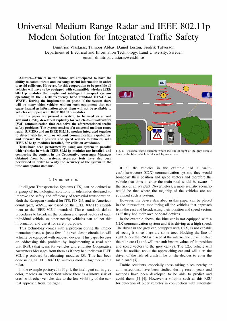
In the example portrayed in Fig. 1, the intelligent car in greycolor, reaches an intersection where there is a known risk ofcrash with other vehicles due to the low visibility of the carsthat approach from the right.
Fig. 1. Possible traffic outcome where the line of sight of the grey vehicletowards the blue vehicle is blocked by some trees.
If all the vehicles in the example had a car-to-car/infrastructure (C2X) communication system, they wouldbroadcast their position and speed vectors and therefore thevehicle that aims to enter the main road would be aware ofthe risk of an accident. Nevertheless, a more realistic scenariowould be that where the majority of the vehicles are notequipped such a system.
However, the device described in this paper can be placedin the intersection, monitoring all the vehicles that approachfrom the east and broadcasting their position and speed vectorsas if they had their own onboard devices.
In the example above, the blue car is not equipped with aC2X communication system and it is driving at a high speed.The driver in the grey car, equipped with C2X, is not capableof seeing it since there are some trees blocking the line ofsight. Since the RSU is placed at the intersection, it will detectthe blue car (1) and will transmit instant values of its positionand speed vectors to the grey car (2). The C2X vehicle willthen be notified about the approaching car and will alert thedriver of the risk of crash if he or she decides to enter themain road (3).
Traffic accidents, especially those taking place nearby orat intersections, have been studied during recent years andmethods have been developed to be able to predict andavoid them [1]–[4]. However, a solution such as this RSUfor detection of older vehicles in conjunction with automatic
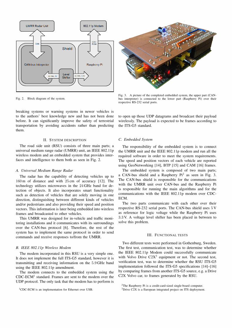
Fig. 2. Block diagram of the system.
breaking systems or warning systems in newer vehicles isto the authors’ best knowledge new and has not been donebefore. It can significantly improve the safety of terrestrialtransportation by avoiding accidents rather than predictingthem.
II. SYSTEM DESCRIPTION
The road side unit (RSU) consists of three main parts; auniversal medium range radar (UMRR) unit, an IEEE 802.11pwireless modem and an embedded system that provides inter-faces and intelligence to them both as seen in Fig. 2.
A. Universal Medium Range Radar
The radar has the capability of detecting vehicles up to160m of distance and with 25 cm of accuracy [12]. Thetechnology utilizes microwaves in the 24GHz band for de-tection of objects. It also incorporates smart functionalitysuch as detection of vehicles that are solely moving in onedirection, distinguishing between different kinds of vehiclesand/or pedestrians and also providing their speed and positionvectors. This information is later being embedded into wirelessframes and broadcasted to other vehicles.
This UMRR was designed for in-vehicle and traffic moni-toring installations and it communicates with its surroundingsover the CAN-bus protocol [6]. Therefore, the rest of thesystem has to implement the same protocol in order to sendcommands and receive responses to/from the UMRR.
B. IEEE 802.11p Wireless Modem
The modem incorporated in this RSU is a very simple one.It does not implement the full ITS-G5 standard, however it istransmitting and receiving information on the 5.9GHz bandusing the IEEE 802.11p amendment.
The modem connects to the embedded system using theCDC-ECM1 standard. Frames are sent to the modem over theUDP protocol. The only task that the modem has to perform is
1CDC-ECM is an implementation for Ethernet over USB.
Fig. 3. A picture of the completed embedded system, the upper part (CAN-bus interpreter) is connected to the lower part (Raspberry Pi) over theirrespective RS-232 serial ports.
to open up those UDP datagrams and broadcast their payloadwirelessly. The payload is expected to be frames according tothe ITS-G5 standard.
C. Embedded System
The responsibility of the embedded system is to connectthe UMRR unit and the IEEE 802.11p modem and run all therequired software in order to meet the system requirements.The speed and position vectors of each vehicle are reportedusing GeoNetworking [14], BTP [15] and CAM [16] frames.
The embedded system is composed of two main parts;a CAN-bus shield and a Raspberry Pi2 as seen in Fig. 3.The CAN-bus shield is responsible for the communicationswith the UMRR unit over CAN-bus and the Raspberry Piis responsible for running the main algorithms and for thecommunications with the IEEE 802.11p modem over CDC-ECM.
The two parts communicate with each other over theirrespective RS-232 serial ports. The CAN-bus shield uses 5Vas reference for logic voltage while the Raspberry Pi uses3.3V. A voltage level shifter has been placed in between tosolve this problem.
III. FUNCTIONAL TESTS
Two different tests were performed in Gothenburg, Sweden.The first test, communication test, was to determine whetherthe IEEE 802.11p Modem could successfully communicatewith Volvo Drive C2X3 equipment or not. The second test,verification test, was to determine whether the RSU ITS-G5implementation followed the ITS-G5 specifications [14]–[16]by comparing frames from another ITS-G5 source, e.g. a DriveC2X Volvo car, to frames generated by the RSU.
2The Raspberry Pi is a credit-card-sized single-board computer.3Drive C2X is a European integrated project on ITS deployment.

(a)
(b)
Fig. 4. (a) Frame received from the RSU and (b) frame received from aDrive C2X Volvo car.
A. Communication testThe RSU was powered up and started broadcasting simu-
lated traffic frames. A Drive C2X receiver was configured andall received wireless frames were saved to a binary file thatwas later inspected in Wireshark4 using ITS-G5 dissectors5.The acquired frames could successfully be interpreted bythe Wireshark dissectors, which meant that the RSU wasgenerating valid GN, BTP and CAM frames with correctformat and that the IEEE 802.11p modem was compatiblewith Drive C2X equipment.
B. Verification testDuring this test a setup with 3 main components was used;
The RSU, a Drive C2X receiver and a Drive C2X Volvo carwith an ITS-G5 implementation.
The RSU was installed and configured next to a road andthe Drive C2X receiver was also installed and configured inthe same spot. The Volvo car was driven on the road next tothe RSU a few times. The external Drive C2X receiver wascapturing frames during this time.
Once the test was completed the captured frames wereanalyzed and compared side by side in Wireshark. An exampleof logged frames can be seen in Fig. 4. The logged frameswere almost identical with the only deviation being the carheading as the heading reported by the RSU was in relationto the direction of the radar while the heading reported by theDrive C2X car was in relation to the North.
The radar bearing was roughly measured with a smartphone, and after compensating for the radar alignment theheading of the car was calculated to 230◦, which is close tothe reported heading of 240◦, and within an acceptable errormargin for a smartphone.
IV. ACCURACY TESTS
Functional tests were performed on the RSU as mentionedabove, but other aspects also needed to be tested. One of thosewas the accuracy of the reported time in conjunction with theaccuracy of the coordinates in the GN/CAM frames down tocentimeter level. Accuracy measurements were performed withthe help of a state of the art GPS positioning device [11].
4Wireshark is a free and open-source packet analyzer.5The ITS-G5 dissectors were fetched from AMB Consulting.
Approaching car
Fig. 5. The RSU pointing towards the street.
Car mounted GPS
Fig. 6. High accuracy GPS with an external antenna mounted on the top ofthe car.
Fig. 7. The long straight part of Dag Hammarskjolds street in Lund,Sweden. The RSU was placed at point A pointing towards point B. Im-ages: c©2013 Cnes/Spot Image, DigitalGlobe, Lantmateriet/Metria. Map data:c©2013 Google.

1425 1430 1435 1440 14450
50
100
150
200X coordinate
Time [s]
Dis
tance [m
]
Data from the RSU
Data from the GPS
1425 1430 1435 1440 1445−3
−2
−1
0Y coordinate
Time [s]
Dis
tance [m
]
Data from the RSU
Data from the GPS
Fig. 8. Positions reported during one of the 22 sample runs. The upper graphdisplays data for the distance from the RSU to the vehicle (X) and the lowergraph displays data for the sidewise movement of the vehicle (Y).
A. Objectives
GeoNetworking and CAM frames contain a timestamp aswell as the WGS846 geographic coordinates of a vehicle[14], [16]. It is very important that the reported timestampis actually the correct timestamp when the vehicle was atthe reported coordinate, because the accuracy of the positionestimate depends on the accuracy of the timestamp. Delaysmight be introduced as a result of processing time that variousalgorithms utilize. Therefore, it is important to measure andreport these delays and their impact on the accuracy of theposition estimate.
B. Methodology
The measurement setup consisted of the RSU on a 5mtripod, see Fig. 5, a high precision GPS receiver that reportscoordinates with errors in the centimeter level range [11]mounted on a Volvo-V70 car, see Fig. 6. A 350m straightpatch of road selected as measurement route, see Fig. 7.
The car drove 22 times down the street towards the RSUwhile logging its coordinates and timestamps with the highprecision GPS receiver. At the same time the RSU was detect-ing the car and also logging its coordinates and timestamps.
GPS time was used on both systems. A GPS receiverwas temporarily fitted on the RSU for time synchronization.According to [7] GPS time is typically accurate within 40 ns,which is more than enough since the maximum loggingresolution of the RSU is 1ms.
C. Results
1) Time errors: The first measurement was used as acalibration run. The goal with this measurement was to findpossible errors in the time domain.
The RSU was using UTC time, since its Network Time Pro-tocol (NTP) daemon was compensating for leap seconds [8].
6WGS84: World Geodetic System 1984, last revised in 2004 according tothe National Geospatial-Intelligence Agency.
1425 1430 1435 1440 1445−2
−1
0
1
2X coordinate
Time [s]
Err
or
[m]
1425 1430 1435 1440 1445−2
−1
0
1
2Y coordinate
Time [s]
Err
or
[m]
Fig. 9. The error between RSU and GPS data from the same measurementas in Fig. 8, as a function of time.
However, the GPS was using pure GPS time and therefore theextra leap seconds were compensated for the RSU. Accordingto [9] the offset between GPS time and Coordinated UniversalTime (UTC) is 16 s, as the current number of leap seconds is16 s [10].
Also a millisecond level fine-tuning was made numericallyon the time offset. The offset that minimized the distance errorwas selected.
2) Spatial errors: The RSU can detect both distance to avehicle (X coordinate) and sidewise movement of a vehicle (Ycoordinate). Thus both directions and their errors were studiedseparately.
In order to find possible errors in the spatial domain allmeasurements were compensated for the time offset. Thedistance from the RSU to the car was compensated for the
0 50 100 150 200−5
0
5X coordinate
Distance [m]
Err
or
[m]
Error points
LS approximation
0 50 100 150 200−5
0
5Y coordinate
Distance [m]
Err
or
[m]
Error points
LS approximation
A B
Fig. 10. Scatter plot displaying the error as a function of distance from theRSU to the car for all measurements. For the X coordinate a deterministicbehaviour can be seen near the radar in section A, which can be compensatedfor by an appropriate model. The standard deviation for X, based on sectionB, is σx = 89 cm and for Y is σy = 38 cm.
value that minimized the mean X-error, and the sidewisemovement of the car was compensated for the position of theGPS device on the car.
In Fig. 8 a sample measurement can be seen. The differencein distance between the RSU and GPS data is the spatial errorwhich can be seen in Fig. 9. However, what is more interestingto analyze is the error of all the measurements as a functionof the distance from the RSU to the car as seen in Fig. 10.From that we can read the standard deviation as a measure ofaccuracy. For X; σx = 89 cm and for Y; σy = 38 cm.
When the car is within 28m from the RSU, a deterministicbehaviour can be observed, as the car is going out of themain beam of the radar, as seen in section A of the uppergraph of Fig. 10. A least squares model that describes thisbehaviour can be found, reversed and added to the data inorder to eliminate the error.
3) Vehicle reference point: It is also of interest to inves-tigate whether the reference point of the RSU on the car ischanging as the car is approaching the RSU. A slope differentfrom zero on the least squares approximation in Fig. 10 wouldindicate that. As it can be seen the slope is equal to 0 bothfor the X and Y directions. Therefore it can be concluded thatthe reference point of the RSU on the car is static.
V. CONCLUSION
Throughout the article a road side unit (RSU) that imple-ments the ITS-G5 standard has been described. It is able to em-ulate car-to-car/infrastructure (C2X) communications of non-intelligent vehicles within the sight of a radar, thus providinga better integration of ITS-G5 vehicles in the future.
An embedded system succeeds on connecting a microwaveradar and an IEEE 802.11p modem, providing an intelligentdevice in the middle that is powerful enough to perform allneeded calculations.
Functional tests have been performed in order to confirmthe RSU’s ability to communicate with other devices thatimplement the same standard and to verify the system’sreported values such as coordinates and speed. Both tests havebeen successful. Accuracy tests have been performed and thesystem’s accuracy shows promising results. The accuracy in Xand Y directions has been measured to ±89 cm and ±38 cmrespectively.
With this technology, intelligent transportation will be re-alized earlier during the implementation phase, where justa small portion of vehicles on public roads will feature acooperative communications system. It is also a long-termsolution, since older vehicles will keep driving on public roadsfor a long time. By implementing the system in blind spots,intelligent vehicles will benefit from extra active safety as theywill be warned about surrounding vehicles.
ACKNOWLEDGMENTS
The authors would like to thank Volvo Cars Corporationfor their cooperation and supply of equipment and vehiclesduring the tests and also the GIS center at Lund Universityfor providing the high precision GPS receiver.
REFERENCES
[1] M. S. Short, G. A. Woelfl, and C.-J. Chang, “Effects of traffic signalinstallation on accidents” Accident Analysis & Prevention, vol. 14, no. 2,pp. 135 – 145, 1982.
[2] N. Stamatiadis, W. C. Taylor, and F. X. McKelvey, “Elderly drivers andintersection accidents” Eno Transportation Foundation, Westport, USA,Tech. Rep. 3, July 1991.
[3] M. Poch and F. Mannering, “Negative binomial analysis of intersection-accident frequencies” Journal of Transportation Engineering, vol. 122,no. 2, pp. 105–113, 1996.
[4] E. Belyaev, P. Molchanov, A. Vinel, Y. Koucheryavy, “The Use ofAutomotive Radars in Video-Based Overtaking Assistance Applications”IEEE Transactions on Intelligent Transportation Systems, vol. 14, no. 3,pp. 1035–1042, 2013.
[5] D. Vlastaras and D. Leston, “Improved Traffic Safety by WirelessVehicular Communication” Department of Electrical and InformationTechnology, Lund University, Lund, Sweden, 2013.
[6] Robert Bosch GmbH, “CAN Specification” Bosch, Germany, 1991.[7] D. W. Allan, N. Ashby, C. C. Hodge, “The Science of Timekeeping,
Application Note 1289” Hewlett Packard, 1997.[8] D. Mills, U. Delaware, J. Martin Ed., ISC, J. Burbank, W. Kasch,
JHU/APL, “Network Time Protocol Version 4: Protocol and AlgorithmsSpecification (RFC5905)” Internet Engineering Task Force (IETF), 2010.
[9] Time Service Department, “Leap Seconds” U.S. Naval Observatory,Washington, DC, USA, 2012.
[10] D. Gambis, “Bulletin C 43” Earth Orientation Center of InternationalEarth Rotation and Reference Systems Service (IERS), Paris, France,2012.
[11] Topcon Positioning Systems, Inc. “Topcon GRS-1, GNSS Receiver andField Controller, Brochure” Topcon, USA, 2013.
[12] Smart Microwave Sensors GmbH, “UMRR Traffic Management SensorFull Documentation” Smartmicro, Germany, 2012.
[13] Kapsch TrafficCom AB, “Product Specification, Test Modem” Kapsch,Sweden, 2012.
[14] European Telecommunications Standards Institute, “ETSI TS 102 636-4-1 V1.1.1” ETSI, France, 2011.
[15] European Telecommunications Standards Institute, “ETSI TS 102 636-5-1 V1.1.1” ETSI, France, 2011.
[16] European Telecommunications Standards Institute, “ETSI TS 102 637-2V1.2.1” ETSI, France, 2011.