united states district court southern...
TRANSCRIPT

J U D G E O E T K E N
UNITED STATES DISTRICT COURT SOUTHERN DISTRICT OF NEW YORK
SULZER MIXPAC USA, INC. and SULZER MIXPAC AG,
Plaintiffs, COMPLAINT
-against- TRIAL BY JURY DEMAND
U.S. DENTAL DEPOT, INC.,
Defendant. •X
Plaintiffs Sulzer Mixpac USA, Inc. and Sulzer Mixpac AG (collectively
"Mixpac" or "Plaintiff") for their complaint against defendant U.S. Dental Depot, Inc.
("Defendant") seeking damages, injunctive relief, and other relief for trademark and patent
infringement, allege as follows:
1. Plaintiff Sulzer Mixpac USA, Inc. is a New Hampshire corporation with
its principal place of business at 8 Willow Street, Salem, New Hampshire 03079.
2. Plaintiff Sulzer Mixpac AG is a Swiss corporation with its principal
place of business at Ruetistrasse 7, CH-9469 Haag, Switzerland.
3. Defendant U.S. Dental Depot is a Florida corporation, having its
principal place of business at 6555 NW 9th Avenue, Suite 121, Fort Lauderdale, Florida
33309.
under 28 U.S.C. §§ 1331 and 1338(a). This court has jurisdiction over Mixpac's trademark
PARTIES
JURISDICTION AND VENUE
4. This court has jurisdiction over Mixpac's patent infringement claims
Case 1:12-cv-00370-RWS Document 1 Filed 01/17/12 Page 1 of 114

and trade-dress infringement claims under 28 U.S.C. §§ 1331 and 1338(a) and 15 U.S.C.
§ 1121.
5. This court has personal jurisdiction over Defendant because it has
transacted and is transacting business in this district, and has sold, offered for sale, distributed,
or advertised products that infringe Mixpac's registered trademarks in this judicial district.
Defendant also has made, used, imported, sold, or offered for sale in the United States,
including within this judicial district, a product which infringes Mixpac's United States Patent
No. 5,918,772 (the "'772 Patent"), and United States Patent No. 6,186,363 (the "<363
Patent"), and Mixpac's trademarks, specifically U.S. Trademark Registration No. 3,762,232
(yellow), Reg. No. 3,762,233 (teal/green), Reg. No. 3,976,379 (blue), Reg. No. 3,976,380 (pink),
Reg. No. 3,976,381 (purple) and Reg. No. 4,051,261 (no color). Defendant has substantial and
continuous contacts with New York and has committed acts of infringement in New York,
including the Southern District of New York, sufficient to confer personal jurisdiction upon
them. Venue properly lays in this court under 28 U.S.C. §§ 1391(b) and (c) and 1400(b)
because defendant is subject to personal jurisdiction and has committed acts of trademark
infringement and patent infringement in this district.
BACKGROUND
The Mixpac three part mixing system
6. Mixpac is the exclusive manufacturer in Switzerland of a patented three-
part system for mixing two-part adhesives for dental and industrial applications. The system
consists of 1) a dispenser like a caulking gun, 2) a cartridge containing a two part chemical
such as an epoxy having a catalyst and a resin, and 3) a mixing tip that mixes the chemicals
before they are applied for making, for example, an impression or mold for teeth.
Case 1:12-cv-00370-RWS Document 1 Filed 01/17/12 Page 2 of 114

The Mixing Tips' Registered Colored Dome Mark 7. Mixpac has since at least as early as 1997 used a distinctive dome shape
and color design Mark for its mixing tips, (hereinafter "Mixpac Colored Dome Mark"). An
image of the Mixpac Colored Dome Mark and line of colored mixing tips appears below.
sw 'x; Si; ^
8. The Colored Dome Mark has been used to identify Mixpac's dental
mixing system and tips.
9. Mixpac's Colored Dome Mark includes the line of mixing tips with six
pleasing "candy-like" colors of yellow, teal, blue, pink, purple and white ("Candy Colors").
10. The Mixpac Colored Dome Mark is non-functional. It is not essential to
the product's purpose, and it is not dictated by concern for cost efficiency. This is evidenced
by the fact that many other companies in the industry also have different designs for their
dental products, none of which include the design features of the Colored Dome Mark.
11. The Mixpac Colored Dome Mark is distinctive and identifies a single
source. Additionally, over the last decade, the Mixpac Colored Dome Mark has acquired
secondary meaning as the relevant public has come to associate the Colored Dome Mark with a
single source - Mixpac. Mixpac informs persons in the dental trade to "look for" the Colored
Dome Mark and Candy Colors. Purchasers choose mixing tips based on the Colored Dome
Mark.
Case 1:12-cv-00370-RWS Document 1 Filed 01/17/12 Page 3 of 114

Defendant's copied Mixing tips
12. Defendant seeks to capitalize on the success of the Mixpac mixing tips
by copying the distinctive Colored Dome Mark, including each of the Candy Colors and
intentionally confuse purchasers into believing the counterfeit products are manufactured or
licensed by Mixpac.
13. Defendant's copied products are of lesser quality and safety and
reliability, and threaten Mixpac's reputation in its product, to the detriment of Mixpac and the
public.
14. Defendant makes, uses, offers for sale or import, markets, distributes,
offers for sale, or sells products that infringe the Colored Dome Mark.
The Colored Dome Mark Federal Trademark Registrations
15. Mixpac was awarded six U.S. Trademark Registrations for the mixing
tips, U.S. Trademark Registration No. 3,762,232 (yellow), Reg. No. 3,762,233 (teal/green), Reg.
No. 3,976,379 (blue), Reg. No. 3,976,380 (pink), Reg. No. 3,976,381 (purple) and Reg. No.
4,051,261 (no color). Copies of the registration certificates are attached as Exhibit A.
Mixing Tips and Cartridge Patents
16. Mixpac owns U.S. patents for the dispenser, cartridge and mixing tips.
17. On July 6, 1999, the '772 Patent was duly and legally issued for an
invention entitled "Bayonet Fastening Device For The Attachment Of An Accessory To A Multiple Component Cartridge Or Dispensing Device." The '772 Patent is assigned to Sulzer
Mixpac AG and is valid and enforceable. A copy of the '772 patent is attached as Exhibit B.
18. On February 13, 2001, the '363 Patent was duly and legally issued for
an invention entitled "Bayonet Fastening Device For The Attachment Of An Accessory To A
Case 1:12-cv-00370-RWS Document 1 Filed 01/17/12 Page 4 of 114

Multiple Component Cartridge Or Dispensing Device" The '363 Patent is assigned to Sulzer
Mixpac AG and is valid and enforceable. A copy of the '363 patent is attached as Exhibit C.
19. Defendant has offered for sale or delivered into this judicial district
mixing tips that infringe the Colored Dome Mark and the '772 and '363 patents.
This Court Has Entered Several Restraining Orders, Consent or Default
Judgments, and a Preliminary Injunction Which Confirm the Validity of The Colored Dome
Mark and the '772 and (363 Patents
20. This Court entered a Temporary Restraining Order against all defendants
barring further infringement of the Colored Dome Mark on December 1, 2008, and the Court
later entered six consent or default judgments which confirm the validity and infringement of the
Colored Dome Mark and the '772 and '363 patents. See Sulzer Mixpac v. TPC Advanced Technologies, Inc., 08 Civ. 10364 (DC). On November 30, 2009, in Sulzer Mixpac v. Ritter GmbH, NSJ and Peng Waves, 09 Civ. 9705 (DAB) the Court issued a TRO, followed by the
issuance of a Preliminary Injunction on December 14, 2009, and later a default judgment
confirming the validity and infringement of Mixpac's Colored Dome Mark and the 4772 and
'363 patents. In Sulzer Mixpac USA v. Purelife Gloves, LLC, l:09-cv-10430-DAB-GWG and
Sulzer Mixpac USA v. Crown Dentalsply et al, l:10-cv-08911-DAB, the court entered consent
judgments further confirming the validity and infringement of the Colored Dome Mark and the
'772 and '363 patents.
COUNT I
TRADEMARK COUNTERFEITING UNDER 15 U.S.C. §1114
21. Mixpac realleges and incorporates herein by reference the allegations in
paragraphs 1 through 20 of its complaint.
Case 1:12-cv-00370-RWS Document 1 Filed 01/17/12 Page 5 of 114

22. Defendant has advertised, offered for sale, distributed or sold mixing tips
which simulate and are substantially indistinguishable from Mixpac's yellow, or teal/green, or
pink, or purple or blue mixing tips as shown in U.S. Trademark Registration No. 3,762,232
(yellow), Reg. No. 3,762,233 (teal/green), Reg. No. 3,976,379 (blue), Reg. No. 3,976,380 (pink),
Reg. No. 3,976,381 (purple) or Reg. No. 4,051,261 (no color).
23. Defendant's conduct is likely to cause confusion, to cause mistake, and to
deceive.
24. Mixpac has no adequate remedy at law. Defendant's conduct has caused
and, if not enjoined, will continue to cause irreparable damage to Mixpac. As a result of
Defendant's wrongful conduct, Mixpac is entitled to injunctive relief, Defendant's profits,
statutory damages, damages, and attorney's fees and costs.
COUNT II
INFRINGEMENT OF THE COLORED DOME MARK UNDER 15 U.S.C. §1125(a)
25. Mixpac realleges and incorporates herein by reference the allegations in
paragraphs 1 through 24 of its complaint.
26. Upon information and belief, Defendant adopted its trade dress for its
mixing tips with knowledge of the Colored Dome Mark.
27. Defendant has misleadingly used, and continues to use, a confusingly
similar trade dress to the Colored Dome Mark, which is likely to cause confusion, to cause
mistake, and to deceive as to Defendant's affiliation, connection, association, or sponsorship
with Mixpac.
28. Defendant's acts are calculated to deceive, or are likely to deceive, the
public, which recognizes and associates the Colored Dome Mark with Mixpac. Moreover,
Case 1:12-cv-00370-RWS Document 1 Filed 01/17/12 Page 6 of 114

Defendant's conduct is likely to cause confusion, to cause mistake, or to deceive the public as
to the source of Defendant's products, or as to a possible affiliation, connection with or
sponsorship by Mixpac.
29. Defendant's conduct has caused Mixpac to suffer and, unless enjoined by
the court, will cause Mixpac to continue to suffer damage to its operation, reputation, and
goodwill and will suffer the loss of sales and profits that Mixpac would have made but for
Defendant's acts. Defendant has been, and will continue to be, unjustly enriched by its
unlawful acts.
30. Mixpac has no adequate remedy at law. Defendant's conduct has caused
and, if not enjoined, will continue to cause irreparable damage to Mixpac. As a result of
Defendant's wrongful conduct, Mixpac is entitled to injunctive relief, Defendant's profits,
damages, and attorney's fees and costs.
COUNT III
FEDERAL UNFAIR COMPETITIONAS TO DEFENDANT'S MIXING TIPS UNDER 15 U.S.C. § 1125(A)
31. Mixpac realleges and incorporates by reference the allegations in
paragraphs 1 through 30 of its complaint.
32. Defendant's mixing tips utilize the Colored Dome Mark in such a way as
to unfairly compete in the marketplace by drawing a false association between Defendant's
products and Mixpac.
33. Defendant has made false designations of origin and false or misleading
descriptions or representations of fact in commercial advertising or promotion which
Case 1:12-cv-00370-RWS Document 1 Filed 01/17/12 Page 7 of 114

misrepresent the nature, characteristics, or qualities of another person's goods, services or
commercial activities in violation of 15 U.S.C. § 1125(a).
34. Defendant has violated and, upon information and belief, intends to
continue to willfully, knowingly, and intentionally violate 15 U.S.C. § 1125(a)(1)(B) by its
unlawful acts in a manner that is likely to cause confusion, mistake, or to deceive as to the
nature, characteristics, or qualities of their goods, services, or commercial activities.
35. Defendant's conduct has caused Mixpac to suffer irreparable harm and,
unless enjoined by the court, will cause Mixpac to continue to suffer damage to its operation,
reputation, and goodwill and will suffer the loss of sales and profits that Mixpac would have
made but for Defendant's acts. Defendant has been, and will continue to be, unjustly enriched
by their unlawful acts.
36. Mixpac has no adequate remedy at law. Defendant's conduct has caused
and, if not enjoined, will continue to cause irreparable damage to Mixpac. As a result of
Defendant's wrongful conduct, Mixpac is entitled to injunctive relief, Defendant's profits,
damages, and attorney's fees and costs.
COUNT IV
FALSE DESIGNATION OF ORIGIN WITH RESPECT TO
DEFENDANT'S MIXING TIPS UNDER 15 U.S.C. § 1125(A)
37. Mixpac realleges and incorporates herein by reference the allegations in
paragraphs 1 through 36 of its complaint.
38. Defendant's mixing tips utilize the Colored Dome Mark in such a way as
to unfairly compete in the marketplace by drawing a false association between Defendant's
products and Mixpac.
Case 1:12-cv-00370-RWS Document 1 Filed 01/17/12 Page 8 of 114

39. Defendant has made false designations of origin and false or misleading
descriptions or representations of fact in commercial advertising or promotion which
misrepresent the nature, characteristics, qualities, sponsorship, or association with another
person's goods, services, or commercial activities in violation of 15 U.S.C. § 1125(a).
40. Defendant has violated and, upon information and belief, intends to
continue to willfully, knowingly, and intentionally violate 15 U.S.C. § 1125(a) by its unlawful
acts in a manner that is likely to cause confusion, mistake or deceive as to the nature,
characteristics, or qualities of its goods, services, or commercial activities.
41. Defendant's conduct has caused Mixpac to suffer irreparable harm and,
unless enjoined by the Court, will cause Mixpac to continue to suffer damage to its operation,
reputation, and goodwill, and will suffer the loss of sales and profits that Mixpac would have
made but for Defendant's acts. Defendant has been, and will continue to be, unjustly enriched
by their unlawful acts.
42. Mixpac has no adequate remedy at law. Defendant's conduct has caused
and, if not enjoined, will continue to cause irreparable damage to Mixpac. As a result of
Defendant's wrongful conduct, Mixpac is entitled to injunctive relief, Defendant's profits,
damages, and attorney's fees and costs.
COUNT V
VIOLATION OF N.Y. GEN. BUS. LAW § 349
43. Mixpac realleges and incorporates herein by reference the allegations in
paragraphs 1 through 42 of its complaint.
44. Defendant's acts, including the unauthorized manufacture and
distribution of its mixing tips, constitute a violation of General Business Law § 349 because
Case 1:12-cv-00370-RWS Document 1 Filed 01/17/12 Page 9 of 114

they are likely to cause confusion or mistake, or deceive consumers into thinking that
Defendant's and Mixpac's products emanate from the same source. The public has an interest
in being able to correctly identify the source of the Mixpac products.
45. Defendant's conduct has caused harm to the public because its products
compromise the health or safety of consumers of dental services.
46. On information and belief, Defendant willfully engaged in one or more
deceptive trade practices.
47. Mixpac has no adequate remedy at law. Defendant's conduct has caused
and, if not enjoined, will continue to endanger consumers of dental services and cause
irreparable damage to Mixpac. As a result of Defendant's wrongful conduct, Mixpac is
entitled to injunctive relief, Defendant's profits, damages and attorney's fees and costs.
COUNT VI
VIOLATION OF N.Y. GEN. BUS. LAW § 350
48. Mixpac realleges and incorporates herein by reference the allegations in
paragraphs 1 through 47 of its complaint.
49. Defendant's acts violate General Business Law § 350 because, by
offering copies of Mixpac's products, it falsely represents to consumers and professionals that
its products are somehow associated or affiliated with, sponsored, or endorsed by Mixpac.
50. Defendant's acts and misrepresentations are likely to cause confusion,
mistake, or deception as to the source of its products and services.
51. Should such misrepresentations continue, it will produce an irreparable
injury to Mixpac because it allows Defendant to trade off Mixpac's goodwill and unfairly and
improperly market its goods through misleading statements.
Case 1:12-cv-00370-RWS Document 1 Filed 01/17/12 Page 10 of 114

52. Defendant's conduct has caused harm to the public because its products / —
compromise the health or safety of consumers of dental services.
53. Defendant's acts have caused, and continue to cause, irreparable harm to
Mixpac. Unless this court enjoins Defendant from continuing its unauthorized acts, Mixpac
will continue to suffer irreparable harm. As a result of Defendant's wrongful conduct, Mixpac
is entitled to injunctive relief, Defendant's profits, damages, and attorney's fees and costs.
COUNT VII
VIOLATION OF N.Y. GEN. BUS. LAW § 360-1
54. Mixpac realleges and incorporates herein by reference the allegations in
paragraphs 1 through 53 of its complaint.
55. Defendant's conduct is likely to cause injury to Mixpac's reputation and
dilute the distinctive quality of its trademarks.
56. Mixpac's Colored Dome Mark is highly distinctive and has become well
known and widely respected in the dental industry.
57. Mixpac's products are FDA compliant and meet the standards of the
Toxic Substances Control Act Inventory (TSCA).
58. Mixpac's mixing tips have been properly tested to fit and work
effectively with its complementary dispensing systems.
59. Upon information and belief, Defendant's products are not FDA
compliant and are made of substandard materials.
60. Defendant's use of Mixpac's Colored Dome Mark on its identical (in
appearance), yet substandard, products is likely to cause consumers to believe that Defendant's
products emanate from the same source as Mixpac's.
Case 1:12-cv-00370-RWS Document 1 Filed 01/17/12 Page 11 of 114

61. Defendant's unlawful manufacture and distribution of products bearing
Mixpac's distinctive trademarks are likely to tarnish Mixpac's image and blur the distinctive
quality of its marks.
62. Defendant's actions threaten to undermine and damage the goodwill and
reputation associated with Mixpac's trademark in the eyes of the dental trade industry and
general consuming public.
63. Defendant's acts have caused, and continue to cause, irreparable harm to
Mixpac. Unless this Court enjoins Defendant from continuing its unauthorized acts, Mixpac
will continue to suffer irreparable harm. As a result of Defendant's wrongful conduct, Mixpac
is entitled to injunctive relief, Defendant's profits, damages, and attorney's fees and costs.
COUNT VIII
COMMON LAW TRADEMARK INFRINGEMENT
64. Mixpac realleges and incorporates herein by reference the allegations in
paragraphs 1 through 63 of its complaint.
65. Upon information and belief, Defendant adopted the look for their
mixing tips with knowledge of the Colored Dome Mark.
66. Defendant has misleadingly used, and continue to use, a confusingly
similar trade dress to the Colored Dome Mark that is likely to cause confusion, to cause
mistake, and to deceive as to defendant's affiliation, connection, association or sponsorship
with Mixpac.
67. Defendant's acts are calculated to deceive, or are likely to deceive, the
public, which recognizes and associates the Colored Dome Mark with Mixpac. Moreover,
Defendant's conduct is likely to cause confusion, to cause mistake, or to deceive the public as
Case 1:12-cv-00370-RWS Document 1 Filed 01/17/12 Page 12 of 114

to the source of Defendant's products, or as to a possible affiliation, connection with, or
sponsorship by Mixpac.
68. Defendant's acts have caused, and continue to cause, irreparable harm to
Mixpac. Unless this court enjoins Defendant from continuing its unauthorized acts, Mixpac
will continue to suffer irreparable harm. As a result of Defendant's wrongful conduct, Mixpac
is entitled to injunctive relief, Defendant's profits, damages, and attorney's fees and costs.
COUNT IX
COMMON LAW UNFAIR COMPETITION
69. Mixpac realleges and incorporates by reference the allegations in
paragraphs 1 through 68 of its complaint.
70. Defendant's acts and uses constitute unfair competition under common
law.
71. Defendant adopted its trade dress in bad faith as it knowingly, willfully,
and intentionally copied the shape and colors of Mixpac's product to trade off Mixpac's labor,
expenditures, and good will.
72. Defendant's mixing tips utilize the Colored Dome Mark in such a way as
to unfairly compete in the marketplace by drawing a false association between Defendant's
products and Mixpac.
73. Defendant has made false designations of origin and false or misleading
descriptions or representations of fact in commercial advertising or promotion which
misrepresent the nature, characteristics, or qualities of another person's goods, services or
commercial activities
Case 1:12-cv-00370-RWS Document 1 Filed 01/17/12 Page 13 of 114

74. Defendant's conduct has caused Mixpac to suffer irreparable harm and,
unless enjoined by the court, will cause Mixpac to continue to suffer damage to its operation,
reputation, and goodwill and will suffer the loss of sales and profits that Mixpac would have
made but for Defendant's acts. Defendant has been, and will continue to be, unjustly enriched
by their unlawful acts.
75. Mixpac has no adequate remedy at law. Defendant's conduct has caused
and, if not enjoined, will continue to cause irreparable damage to Mixpac. As a result of
Defendant's wrongful conduct, Mixpac is entitled to injunctive relief, Defendant's profits,
damages, and attorney's fees and costs.
COUNT X
PATENT INFRINGEMENT OF U.S. PATENT NO. 5,918,772
76. Plaintiff realleges and incorporates herein by reference the allegations in
paragraphs 1 through 75 of its complaint.
77. Upon information and belief, by making, using, importing, selling, or
offering to sell their mixing tips, Defendant has infringed one or more claims of the '772
Patent directly, contributorily, or through inducement. Defendant has engaged in the
foregoing conduct with respect to the patented invention in the United States without authority
from Mixpac during the term of the '772 Patent.
78. Upon information and belief, Defendant will not stop using, selling,
and/or offering for sale the products at issue to avoid infringing the '772 Patent.
79. Upon information and belief, Defendant's infringement has been
deliberate, willful, and wanton, and with lull knowledge of the '772 Patent.
Case 1:12-cv-00370-RWS Document 1 Filed 01/17/12 Page 14 of 114

80. Defendant's conduct has caused Plaintiff to suffer and, unless enjoined
by the court, will cause Plaintiff to continue to suffer damage to their operation, reputation,
and goodwill.
81. Mixpac has no adequate remedy at law. Defendant's conduct has caused
and, if not enjoined, will continue to cause irreparable damage to Mixpac. As a result of
Defendant's wrongful conduct, Mixpac is entitled to a temporary restraining order, injunctive
relief, and damages.
COUNT XI
PATENT INFRINGEMENT OF U.S. PATENT NO. 6,186,363
82. Mixpac realleges and incorporates by reference the allegations in
paragraphs 1 through 81 of its complaint.
83. Upon information and belief, by making, using, selling, or offering to
sell mixing tips incorporating Mixpac's design features, Defendant has infringed one or more
claims of the '363 Patent directly, contributorily, or through inducement. Defendant has
engaged in the foregoing conduct with respect to the patented invention in the United States
without authority from Mixpac and during the term of the '363 patent.
84. Upon information and belief, Defendant will not stop using, selling, or
offering for sale the methods at issue to avoid infringing the '363 Patent.
85. Upon information and belief, Defendant's infringement has been
deliberate, willful, and wanton, and with full knowledge of the '363 Patent.
86. Defendant's conduct has caused Mixpac to suffer and, unless enjoined by
the court, will cause Mixpac to continue to suffer damage to its operation, reputation, and
goodwill.
Case 1:12-cv-00370-RWS Document 1 Filed 01/17/12 Page 15 of 114

87. Mixpac has no adequate remedy at law. Defendant's conduct has caused
and, if not enjoined, will continue to cause irreparable damage to Mixpac. As a result of
Defendant's wrongful conduct, Mixpac is entitled to a temporary restraining order, injunctive
relief, and damages.
RELIEF REQUESTED
Wherefore, Mixpac requests that the court enter a judgment in Mixpac's favor
and against defendant and provide Mixpac the following relief:
A. Order, adjudge, and decree that Defendant has infringed the Mixpac
Colored Dome Mark under 15 U.S.C. §§ 1114 and 1125(a);
B. Order, adjudge, and decree that Defendant willfully and knowingly
infringed the Mixpac Colored Dome Mark;
C. Issue a temporary restraining order and preliminary and permanent
injunctive relief prohibiting Defendant and its respective parents,
subsidiaries, principals, officers, agents, affiliates, servants, attorneys,
employees, and all others in privity with them from using any trade dress
which is likely to be confused with the Colored Dome Mark;
D. Order Defendant to identify and recall from customers and destroy all
infringing materials, including but not limited to all packaging and
advertising incorporating the infringing trade dress or any other trade dress
confusingly similar to the Colored Dome Mark;
E. Award Mixpac damages for trademark infringement including
prejudgment interest and costs against Defendant under 15 U.S.C. § 1117;
F. Award Mixpac three times its damages to compensate Mixpac under 15
U.S.C. § 1117;
Case 1:12-cv-00370-RWS Document 1 Filed 01/17/12 Page 16 of 114

G. Award Mixpac its reasonable attorney's fees under 15 U.S.C. § 1117;
H. Award Mixpac statutory damages for trademark counterfeiting pursuant to
15 U.S.C. § 1117;
I. Order, adjudge, and decree that Defendant has infringed the '772 and '
363 Patents;
J. Order, adjudge, and decree that Defendant willfully and knowingly
infringed the '772 and '363 Patents;
K. Order, adjudge, and decree that Defendant's infringement of the '772 and
'363 patents is exceptional under 35 U.S.C. § 285;
L. Issue temporary, preliminary, and permanent injunctive relief prohibiting
Defendant and its respective parents, subsidiaries, principals, officers,
agents, affiliates, servants, attorneys, employees, and all others in privity
with them from infringing the '772 and '363 Patents;
M. Award Mixpac damages for patent infringement including prejudgment
interest and costs against Defendant under 35 U.S.C. § 284;
N. Award Mixpac three times its damages to compensate Plaintiff under 35
U.S.C. § 284;
O. Award Mixpac its reasonable attorney's fees under 35 U.S.C. § 285; and
P. Award such other and further relief as the court may deem just.
Case 1:12-cv-00370-RWS Document 1 Filed 01/17/12 Page 17 of 114

Dated: New York, New York January 17, 2012
Respectfully submitted,
^ A f u i ^ « Charles D. Cole, Jr. / Newman Myers Kreines Gross Harris, P C. 14 Wall Street New York, New York 10005-2101 (212) 619-4350
-and-
Michael T. Murphy Benita Collier K&L Gates LLP 1601 K Street, N.W. Washington, D.C. 20006 (202) 778-9176 Attorneys for Plaintiffs Sulzer Mixpac USA,
Inc. and Sulzer Mixpac AG
Case 1:12-cv-00370-RWS Document 1 Filed 01/17/12 Page 18 of 114

Case 1:12-cv-00370-RWS Document 1 Filed 01/17/12 Page 19 of 114

Reg. No. 3,762,232 SULZERMIXPACAG (SWITZERLAND CORPORATION) Registered Mar. 23,2010 GRUNDSTRASSE 12
ROTKREUZ, SWITZERLAND CH-6343
I n t . C l s . : 7 , 8 a n d 1 0 FOR: MIXING HPS USED WITH DISPENSERS OF TWO PART COMPOSITIONS FOR USE IN CONNECTION WITH POWER-OPERATED AND MACHINE-OPERATED DISPENSING GUNS USED FOR MIXING ADHESIVES AND SEALANTS FOR USE IN THE CONSTRUC-
T R A D E M A R K XION, AUTOMOTIVE, ELECTRONICS, AEROSPACE, AND INDUSTRIAL ASSEMBLY AND PRINCIPAL REGISTER REPAIR INDUSTRIES, IN CLASS 7 (U.S. CLS. 13,19,21,23,31,34 AND 35).
FIRST USE 12-31-1997; IN COMMERCE 12-31-1997.
FOR: MIXING HPS USED WITH DISPENSERS OF TWO PART COMPOSITIONS FOR USE IN CONNECTION WITH MANUALLY-OPERATED DISPENSING GUNS USED FOR MIXING ADHESIVES AND SEALANTS FOR USE IN THE CONSTRUCTION, AUTOMOTIVE, ELECTRONICS, AEROSPACE, AND INDUSTRIAL ASSEMBLY AND REPAIR INDUSTRIES, IN CLASS 8 (U.S. CLS. 23,28 AND 44).
FIRST USE 12-31-1997- IN COMMERCE 12-31-1997.
Direvturuf the United Sluto talent and "I ludeinurk OfTic*
FOR: MIXING TIPS USED WITH DISPENSERS OF TWO PART COMPOSITIONS FOR DENTAL APPLICATIONS, IN CLASS 10(U.S. CLS. 26,39AND44).
FIRST USE 12-31-1997; IN COMMERCE 12-31-1997.
THE MARK CONSISTS OF THE COLOR YELLOW AND THE CONFIGURATION OF A FU-TURISTIC, DOME-FAÇADE TIP HAVING A SMOOTH BOTTOM PORTION, A SLIGHTLY INDENTED MIDDLE PORTION, AN UPPER PORTION ANGLED INWARDLY WHICH NARROWS AND RESTRICTS TO A TOP PORTION THAT ATTACHES TO A TRANSPARENT STEM WHICH ENCASES A CORKSCREW LIKE ELEMENT, THE DOTTED OUTLINE OF THE BOTTOM TAB AND TOP TABS ON THE DOME-FAÇADE TIP, THE SLIGHTLY INDEN-TED MIDDLE PORTION CONSISTING OF UNIFORM CONTINUOUS RIDGES, THE STEM AND HIE CORKSCREW LIKE ELEMENT IS INTENDED TO SHOW POSIHON OF THE MARK ON THE GOODS AND ÎS NOT PART OF THE MARK.
THE COLOR(S) YELLOW IS/ARE CLAIMED AS A FEATURE OF THE MARK.
Case 1:12-cv-00370-RWS Document 1 Filed 01/17/12 Page 20 of 114

Reg. No. 3,762,232 SEC. 2(F). SER. NO. 77-623,873, FILED 12-1-2008.
NORA BUCHANAN WILL, EXAMINING ATTORNEY
Page: 2 / RN # 3,762,232
Case 1:12-cv-00370-RWS Document 1 Filed 01/17/12 Page 21 of 114

r ^ i X e ì j s t a t e s o f 8 m e t i
® n i t e b S t a t e s ; p a t e n t a n * ® r a f o e m a r & © f f t c e V H
Reg. No. 3,976,379 SULZER MIXPAC AG (SWITZERLAND CORPORATION) ROTISTRASSE 7
Registered June 14,2011 HAAG(RHEINTAL), SWITZERLAND CH-9469
Int. €1.: 10
TRADEMARK
PRINCIPAL REGISTER
FOR: MIXING TIPS USED WITH DISPENSERS OF TWO PART COMPOSITIONS FOR DENTAL APPLICATIONS, IN CLASS 10 (U.S. CLS. 26,39 AND 44).
FIRST USE 12-31-1997; IN COMMERCE 12-31-1997.
THE MARK CONSISTS OF THE COLOR BLUE AND THE CONFIGURATION OF A FUTUR-ISTIC, DOME-FACADE TIP HAVING A SMOOTH BOTTOM PORTION, A SLIGHTLY IN-DENTED MIDDLE PORTION, AN UPPER PORTION ANGLED INWARDLY WHICH NAR-ROWS AND RESTRICTS TO A TOP PORTION THAT ATTACHES TO A TRANSPARENT STEM WHICH ENCASES A CORKSCREW LIKE ELEMENT. THE DOITED OUTLINE OF THE BOTTOM TAB AND TOP TABS ON THE DOME-FACADE TIP, THE SLIGHTLY INDEN-TED MIDDLE PORTION CONSISTING OF UNIFORM CONTINUOUS RIDGES, THE STEM AND THE CORKSCREW LIKE ELEMENT IS INTENDED TO SHOW POSITION OF THE MARK ON THE GOODS AND IS NOT PART OF THE MARK.
THE COLOR(S) BLUE IS/ARE CLAIMED AS A FEATURE OF THE MARK.
SEC, 2(F).
SER. NO. 77-848,301, FILED 10-14-2009.
NORA BUCHANAN WILL, EXAMINING ATTORNEY
Director of the United Stales Patent unti Tnuiciuiuk OfYkt
Case 1:12-cv-00370-RWS Document 1 Filed 01/17/12 Page 22 of 114

^ i t e ì > s t a t e s o f ® m e
W i n i r n p a t e n t a n b t E r a f c e m a r f c © f f t c e v t f
i
V-J
Reg. No. 3,976,381 SULZER MIXPAC AG (SWITZERLAND CORPORATION) RÜTISTRASSE7
Registered June 14,2011 HAAG (RHEINTAL), SWITZERLAND CH-9469
Int. CI.: 10
TRADEMARK
PRINCIPAL REGISTER
FOR: MIXING TIPS USED WITII DISPENSERS OF TWO PART COMPOSITIONS FOR DENTAL APPLICATIONS, IN CLASS 10 (U.S. CLS. 26,39 AND 44).
FIRST USE 12-31-1997; IN COMMERCE 12-31-1997.
THE MARK CONSISTS OF THE COLOR PURPLE AND THE CONFIGURATION OF A FU-TURISTIC, DOME-FACADE TIP HAVING A SMOOTH BOTTOM PORTION, A SLIGHTLY INDENTED MIDDLE PORTION, AN UPPER PORTION ANGLED INWARDLY WHICH NARROWS AND RESTRICTS TO A TOP PORTION THAT ATTACHES TO A TRANSPARENT STEM WHICH ENCASES A CORKSCREW LIKE ELEMENT. THE DOTTED OUTLINE OF THE BOTTOM TAB AND TOP TABS ON THE DOME- FACADE TIP, THE SLIGHTLY IN-DENTED MIDDLE PORTION CONSISTING OF UNIFORM CONTINUOUS RIDGES, THE STEM AND THE CORKSCREW LIKE ELEMENT IS INTENDED TO SHOW POSITION OF THE MARK ON THE GOODS AND IS NOT PART OF THE MARK.
THE COLOR(S) PURPLE IS/ARE CLAIMED AS A FEATURE OF THE MARK.
SEC. 2(F).
SER. NO, 77-848,320, FILED 10-14-2009.
NORA BUCHANAN WILL, EXAMINING ATTORNEY
Director of the United Slates Paleiit unü Trademark Oifico
Case 1:12-cv-00370-RWS Document 1 Filed 01/17/12 Page 23 of 114

M i t * s t a t e s o f toners. V Z V * ®tot te& S t a t e s i p a t e n t a u b Œ r a & e m a r f c O f f i c e
i
¡Ä
Reg. No. 3,762,233 SULZER MIXPAC AG (SWITZERLAND CORPORATION) Registered Mar. 23,2010 GRUNDSTRASSE 12
ROTKREUZ, SWITZERLAND CH-6343
I n t . C l s . : 7 , 8 a n d 1 0 FOR: MIXING TIPS USED WITH DISPENSERS OF TWO PART COMPOSITIONS FOR USE IN CONNECTION WITH POWER-OPERATED AND MACHINE-OPERATED DISPENSING GUNS USED FOR MIXING ADHESIVES AND SEALANTS FOR USE IN THE CONSTRUC-
T R A D E M A R K HON, AUTOMOTIVE, ELECTRONICS, AEROSPACE, AND INDUSTRIAL ASSEMBLY AND PRINCIPAL REGISTER REPAIR INDUSTRIES, IN CLASS 7 (U.S. CLS. 13,19,21,23, 31,34 AND 35).
FIRST USE 12-31-1997; IN COMMERCE 12-31-1997.
FOR: MIXING HPS USED WITH DISPENSERS OF TWO PART COMPOSITIONS FOR USE IN CONNECTION WITH MANUALLY-OPERATED DISPENSING GUNS USED FOR MIXING ADHESIVES AND SEALANTS FOR USE IN THE CONSTRUCTION, AUTOMOTIVE, ELECTRONICS, AEROSPACE, AND INDUSTRIAL ASSEMBLY AND REPAIR INDUSTRIES, IN CLASS 8 (U.S. CLS. 23,28 AND 44).
FIRST USE 12-31-1997; IN COMMERCE 12-31-1997.
FOR: MIXING TIPS USED WITH DISPENSERS OF TWO PART COMPOSITIONS FOR DENTAL APPLICATIONS, IN CLASS 10 (U.S, CLS. 26,39 AND 44).
FIRST USE 12-31-1997; IN COMMERCE 12-31-1997.
THE MARK CONSISTS OF THE COLOR TEAL AND THE CONFIGURATION OF A FUTUR-ISTIC, DOME-FAÇADE TIP HAVING A SMOOTH BOTTOM PORTION, A SLIGHTLY IN-DENTED MIDDLE PORTION, AN UPPER PORTION ANGLED INWARDLY WHICH NAR-ROWS AND RESTRICTS TO A TOP PORTION THAT ATTACHES TO A TRANSPARENT STEM WHICH ENCASES A CORKSCREW LIKE ELEMENT. THE DOTTED OUTLINE OF THE BOTTOM TAB AND TOP TABS ON THE DOME-FAÇADE TIP, THE SLIGHTLY INDEN-TED MIDDLE PORTION CONSISTING OF UNIFORM CONTINUOUS RIDGES, THE STEM AND THE CORKSCREW LIKE ELEMENT IS INTENDED TO SHOW POSITION OF THE MARK ON THE GOODS AND IS NOT PART OF THE MARK.
THE COLOR(S) TEAL IS/ARE CLAIMED AS A FEATURE OF THE MARK. Diietlur of (ÌK United Slates. Munt und iYuckuiwk Office
Case 1:12-cv-00370-RWS Document 1 Filed 01/17/12 Page 24 of 114

Reg. No. 3,762,233 SEC. 2(F). SER. NO. 77-623,884, FILED 12-1-2008.
NORA BUCHANAN WILL, EXAMINING ATTORNEY
Page: 2 /RN# 3,762,233
Case 1:12-cv-00370-RWS Document 1 Filed 01/17/12 Page 25 of 114

statesi oí &tti Wíníttb á^tatetf p a t e n t a n b t E r a & e m a r f c O f f i c e
V'
Reg. No. 3,976,380 SULZER MIXPAC AG (SWITZERLAND CORPORATION) RÜTISTRASSE 7
Registered June 14,2011 HAAG (RHEINTAL), SWITZERLAND CH-9469
Int. CI.: 10
TRADEMARK
PRINCIPAL REGISTER
FOR: MIXING TIPS USED WITH DISPENSERS OF TWO PART COMPOSITIONS FOR DENTAL APPLICATIONS, IN CLASS 10(U.S. CLS. 26,39 AND 44).
FIRST USE 12-31-1997; IN COMMERCE 12-31-1997.
THE MARK CONSISTS OF THE COLOR PINK AND THE CONFIGURATION OF A FUTUR-ISTIC, DOME-FACADE TIP HAVING A SMOOTH BOTTOM PORTION, A SLIGHTLY IN-DENTED MIDDLE PORTION, AN UPPER PORTION ANGLED INWARDLY WHICH NAR-ROWS AND RESTRICTS TO A TOP PORTION THAT ATTACHES TO A TRANSPARENT STEM WHICH ENCASES A CORKSCREW LIKE ELEMENT. THE DOTTED OUTLINE OF THE BOTTOM TAB AND TOP TABS ON THE DOME-FACADE TIP, THE SLIGHTLY INDEN-TED MIDDLE PORTION CONSISTING OF UNIFORM CONTINUOUS RIDGES, THE STEM AND THE CORKSCREW LIKE ELEMENT IS INTENDED TO SHOW POSITION OF THE MARK ON THE GOODS AND IS NOT PART OF THE MARK.
THE COLOR(S) PINK IS/ARE CLAIMED AS A FEATURE OF THE MARK.
SEC. 2(F).
SER. NO. 77-848,315, FILED 10-14-2009.
NORA BUCHANAN WILL, EXAMINING ATTORNEY
Director uftlic United Stales Patatl luid Tradeiiintft Office
Case 1:12-cv-00370-RWS Document 1 Filed 01/17/12 Page 26 of 114

^ i t t ì s s t a t e s o f VIV* { B u t t e * Statesi p a t e n t mit t & r a f c e m a r k O f f i c e
rr :|53j v
l-ll
Reg. No. 4,051,261 SULZER MEXPAC AG (SWITZERLAND CORPORATION) RUTISTRASSE 7
Registered Nov. 8, 2011 IIAAG (RHEINTAL), SWITZERLAND CH9469
Int. CL: 10
TRADEMARK
PRINCIPAL REGISTER
FOR: MIXING TIPS USED WITH DISPENSERS OF TWO PART COMPOSITIONS FOR DENTAL APPLICATIONS, IN CLASS 10 (U.S. CLS. 26,39AND 44).
FIRST USE 12-31-1997; IN COMMERCE 12-31-1997.
OWNER OF U.S. REG. NOS. 3,762,232 AND 3,762,233.
THE MARK CONSISTS OF THE CONFIGURATION OF A FUTURISTIC, DOME-FACADE TIP HAVING A SMOOTH BOTTOM PORTION, A SLIGHTLY INDENTED MIDDLE PORTION, AN UPPER PORTION ANGLED INWARDLY WHICH NARROWS AND RESTRICTS TO A TOP PORTION THAT ATTACHES TO A TRANSPARENT STEM WHICH ENCASES A CORKSCREW LIKE ELEMENT. THE DOTTED OUTLINE OF THE BOTTOM TAB AND TOP TABS ON THE DOME-FACADE TIP, THE SLIGHTLY INDENTED MIDDLE PORTION CONSISTING OF UNIFORM CONTINUOUS RIDGES, THE STEM AND THE CORKSCREW LIKE ELEMENT IS INTENDED TO SHOW POSITION OF THE MARK ON THE GOODS AND IS NOT PART OF THE MARK.
SEC. 2(F).
SER. NO. 77-848,340, FILED 10-14-2009.
ANN E. SAPPENFIELD, EXAMINING ATTORNEY
Director uf (lie Untied Slulcs Putent und Iradciuijjk Office
Case 1:12-cv-00370-RWS Document 1 Filed 01/17/12 Page 27 of 114

REQUIREMENTS TO MAINTAIN YOUR FEDERAL TRADEMARK REGISTRATION
WARNING: YOUR REGISTRATION WILL BE CANCELLED IF YOU DO NOT FILE THE DOCUMENTS BELOW DURING THE SPECIFIED TIME PERIODS.
Requirements in the First Ten Years* What and When to File:
First Filing Deadline: You must file a Declaration of Use (or Excusable Nonuse) between the 5th and 6th years after the registration date. See 15U.S.C. §§1058,1141k. If the declaration is accepted, the registration will continue in force for the remainder of the ten-year period, calculated from the registration date, unless cancelled by an order of the Commissioner for Trademarks or a federal court.
Second Filing Deadline: You must file a Declaration of Use (or Excusable Nonuse) and an Application for Renewal between the 9th and 10th years after the registration date. * See 15 U.S.C. §1059.
Requirements in Successive Ten-Year Periods* What and When to File:
You must file a Declaration of Use (or Excusable Nonuse) and an Application for Renewal between eveiy 9th and 10th-year period, calculated from the registration date.*
Grace Period Filings*
The above documents will be accepted as timely if filed within six months after the deadlines listed above with the payment of an additional fee.
The United States Patent and Trademark Office (USPTO) will NOT send you any future notice or reminder of these filing requirements.
»ATTENTION MADRID PROTOCOL REGISTRANTS: The holder of an international registration with an extension of protection to the United States under the Madrid Protocol must timely file the Declarations of Use (or Excusable Nonuse) referenced above directly with the USPTO. The time periods for filing are based on the U.S. registration date (not the international registration date). The deadlines and grace periods for the Declarations of Use (or Excusable Nonuse) are identical to those for nationally issued registrations. See 15 U. S.C. §§ 1058,114Ik. However, owners of international registrations do not file renewal applications at the USPTO. Instead, the holder must file a renewal of the underlying international registration at the International Bureau of the World Intellectual Properly Organization, under Article 7 of the Madrid Protocol, before the expiration of each ten-year term of protection, calculated from the date of the international registration. See 15U.S.C. § 114Ij. For more information and renewal forms for the international registration, see http://www.wipo.int/madrid/en/.
NOTE: Fees and requirements for maintaining registrations arc subject to change. Please check the USPTO website for further information. With the exception of renewal applications for registered extensions of protection, you can lile the registration maintenance documents referenced above online at http://www.uspto.gov.
Page: 2 /RN# 4,051,261
Case 1:12-cv-00370-RWS Document 1 Filed 01/17/12 Page 28 of 114

i
Exhibit B
Case 1:12-cv-00370-RWS Document 1 Filed 01/17/12 Page 29 of 114

US006186363B1
(12) United States Patent m Patent No.: us 6,186,363 Bl ( Keller et al. m Date of Patent: Feb. 13,2001
(54) BAYONET FASTENING DEVICE FOR THE ATTACHMENT OF AN ACCESSORY TO A MULTIPLE COMPONENT CARTRIDGE OR DISPENSING DEVICE
(75) Inventors: Wilhelm A. Keller, Obstgartenweg 9, CH-6402 Merlischacben (CH): Richard J. Wilson, Antlover. MA (US)
(73) Assignee: Wilhelm A. Keller, Merlischachen (CH)
( * ) Notice: Under 35 U.S.C. 154(b). the term of this patent shall be extended for 0 days.
(21) Appl. No.: 09/348,038 (22) Filed: Jul. 6, 1999
Related U.S. Application Data
(63) Continuation of application No. 08/563,109, filed on Nov. 27,1995, cow Pat. No. 5,918,772, which is a continuation-in-part of application No. 08/403,172, filed oa Mar. 13, 1995, now abandoned, and a continuation-in-part of appli-cation No. 08/522,109. filed on Aug. 31. 1995, now aban-doned.
(30) Foreign Application Priority Data Aug. 24, 1995 (EP) 95810531
(51) Int. CI.7 B67D 5/56 (52) V.S. CI 222/145.6; 222/145.5;
222/137 (58) Field of Search 222/145,5,145.6,
222/567.326,327.136, 137; 285/360. 361,376, 401, 396, 400, 402, 915
(56) References Cited
U.S. PATENT DOCUMENTS 2,816,518 12/1957 Daggett. 3.143,255 8/19*54 Leeds. 3,323,682 6/1967 Creighton et al. . 3,884,388 5/1975 Holcomb . 4,014,463 3/1977 Hermann .
4,117,551 9/1978 Books et al. . 4.240,566 12/1980 Bergman . 4.432.469 2/1984 Eble et al.. 4,471.888 9/1984 Herb et al. . 4.538,920 9/1985 4,566,610 1/1986 Herb . 4,687,663 8/1987 Schaeffer. 4,690,306 9/1987 Staeheli. 4,747,517 5/1988 Hart. 4.753,536 6/1988 Spehar et al. , 4,767,026 8/1988 4.771.919 9/1988 Enist. 4,846.373 7/1989 Penn et al, . 4.869,400 9/1989 Jacobs . 4,871,090 10/1989 Hoffman . 4.913,553 4/1990 Fnlco . 4,946,079 8/1990 Campbell, 4,974,756 12/1990 Pearson et al.. 4.978.336 12/1990 Capozzi et al.. 4,981,241 1/1991 Keller . 4,989,758 2/1991 Keller
222/145.6
222/145.6
222/145.6
(List continued on next page.)
FOREIGN PATENT DOCUMENTS 0 730 913 * 11/1996 (EP) .
2232910 1/1991 (GB).
* cited by examiner
Primary Examiner—Kenneth Bomberg (74) Attorney, Agent; or Firm—Foley & Lardner (57) ABSTRACT
Abayonet attachment on a cartridge for attaching a mixer or accessory to a multiple component cartridge is formed as a ring-shaped bayonet socket with two internal recesses and two diametrically opposed cutouts forming one bayonet coupling part, whereas the bayonet attachment of the mixer or accessory comprises two bayonet lugs corresponding to the cutouts. In a preferred embodiment, the respective inlets of the mixer housing or the outlets of the cartridge have different sizes or shapes to provide coded alignment between the cartridge and the mixer.
7 Claims, 30 Drawing Sheets
Case 1:12-cv-00370-RWS Document 1 Filed 01/17/12 Page 30 of 114
US 6,186,363 fil Page 2
U.S. PAIENT DOCUMENTS 5,137,182 8/1992 Keller 222/145.6 5.228.599 7/1993 Keller .
4,995,540 2/1991 Colin et at. . 5,249.709 10/1993 Duckworth et al. . 5,020,694 6/1991 Pettengill. 5.249,862 10/1993 Herold et al. . 5,022,563 6/1991 Marchitto et al.. 5,289,949 3/1994 Geatile . 5,033,650 7/1991 Colin et al. . 5.333.760 8/1994 5.038,963 8/1991 Pettengill el al. . 5,413,253 5/1995 222/145.6 5,065,906 11/1991 Maeder. 5.609.271 * 3/1997 222/145.6 5,080.262 1/1992 Herold ef al. . 5,918,772 * 7/1999 Keller et al .. . 222/145.6
Case 1:12-cv-00370-RWS Document 1 Filed 01/17/12 Page 31 of 114

U. S. Patent Feb. 13,2001 Sheet 18 of 30 US 6,186,363 B1
FIG. 1
1 8 3S 9 11
FIG. 2
6 10
Case 1:12-cv-00370-RWS Document 1 Filed 01/17/12 Page 32 of 114

U. S. Patent Feb. 13,2001 Sheet 18 of 30 US 6,186,363 B1
FIG. 3
FIG. 4
Case 1:12-cv-00370-RWS Document 1 Filed 01/17/12 Page 33 of 114
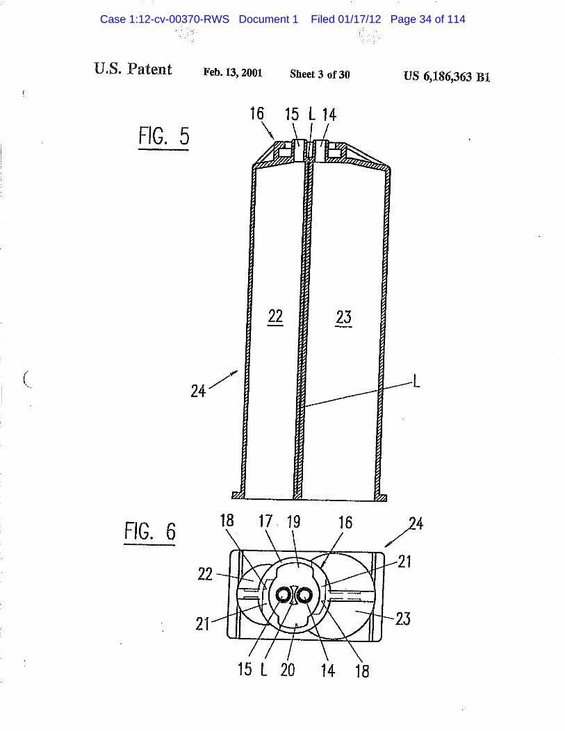
U. S. Patent Feb. 13,2001 Sheet 18 of 30 US 6,186,363 B1
(
FIG. 5
FIG. 6
15 L 20 14 18
Case 1:12-cv-00370-RWS Document 1 Filed 01/17/12 Page 34 of 114

U. S. Patent Feb. 13,2001 Sheet 18 of 30 US 6,186,363 B1
FIG. 7
K vexa
26 k /
25
r w p
3S 9
FIG. 8
28 9
30
29
Case 1:12-cv-00370-RWS Document 1 Filed 01/17/12 Page 35 of 114

U. S. Patent Feb. 13,2001 Sheet 18 of 30 US 6,186,363 B1
FIG. 8A
9-x 28a
29a
FIG. 9A
15a 14a
Case 1:12-cv-00370-RWS Document 1 Filed 01/17/12 Page 36 of 114

U. S. Patent Feb. 13,2001 Sheet 18 of 30 US 6,186,363 B1
FIG. 9
3 5
FIG. 10
16 15 36 14 \ \±¿
m
13 13
.M
18 17 19 3 6 16 I L
15 20 14 18
Case 1:12-cv-00370-RWS Document 1 Filed 01/17/12 Page 37 of 114

U. S. Patent Feb. 13,2001 Sheet 18 of 30 US 6,186,363 B1
FIG. 11
FIG. 12
Case 1:12-cv-00370-RWS Document 1 Filed 01/17/12 Page 38 of 114

U. S. Patent Feb. 13,2001 Sheet 18 of 30 US 6,186,363 B1
FIG. 13 /
3 8
< '.•.vi'
75
Case 1:12-cv-00370-RWS Document 1 Filed 01/17/12 Page 39 of 114

U. S. Patent Feb. 13,2001 Sheet 18 of 30 US 6,186,363 B1
46 L 45 47
FIG. 14
43 43
L
4 2
m. FIG. 15
M m
46 44
Case 1:12-cv-00370-RWS Document 1 Filed 01/17/12 Page 40 of 114

U. S. Patent Feb. 13,2001 Sheet 18 of 30 US 6,186,363 B1
FIG. 16A FIG. 16B
FIG. 17
55 54 55
Case 1:12-cv-00370-RWS Document 1 Filed 01/17/12 Page 41 of 114

U.S. Patent Feb. 13,2001 Sheet 11 of 30 US 6,186,363 B1
FIG. 18 FIG. 19
Case 1:12-cv-00370-RWS Document 1 Filed 01/17/12 Page 42 of 114

U. S. Patent Feb. 13,2001 Sheet 18 of 30 US 6,186,363 B1
FIG. 20 FIG. 21
63Â 65
FIG. 22 FIG. 23
Case 1:12-cv-00370-RWS Document 1 Filed 01/17/12 Page 43 of 114

U.S. Patent Feb. 13,2001 Sheet 13 of 30 US 6,186,363 B1
FIG. 24
71 70
FIG. 25
Case 1:12-cv-00370-RWS Document 1 Filed 01/17/12 Page 44 of 114

U. S. Patent Feb. 13,2001 Sheet 18 of 30 US 6,186,363 B1
FIG. 26
(
Case 1:12-cv-00370-RWS Document 1 Filed 01/17/12 Page 45 of 114
U.S. Patent Feb. 13,2001 Sheet 15 of 30 US 6,186,363 B1
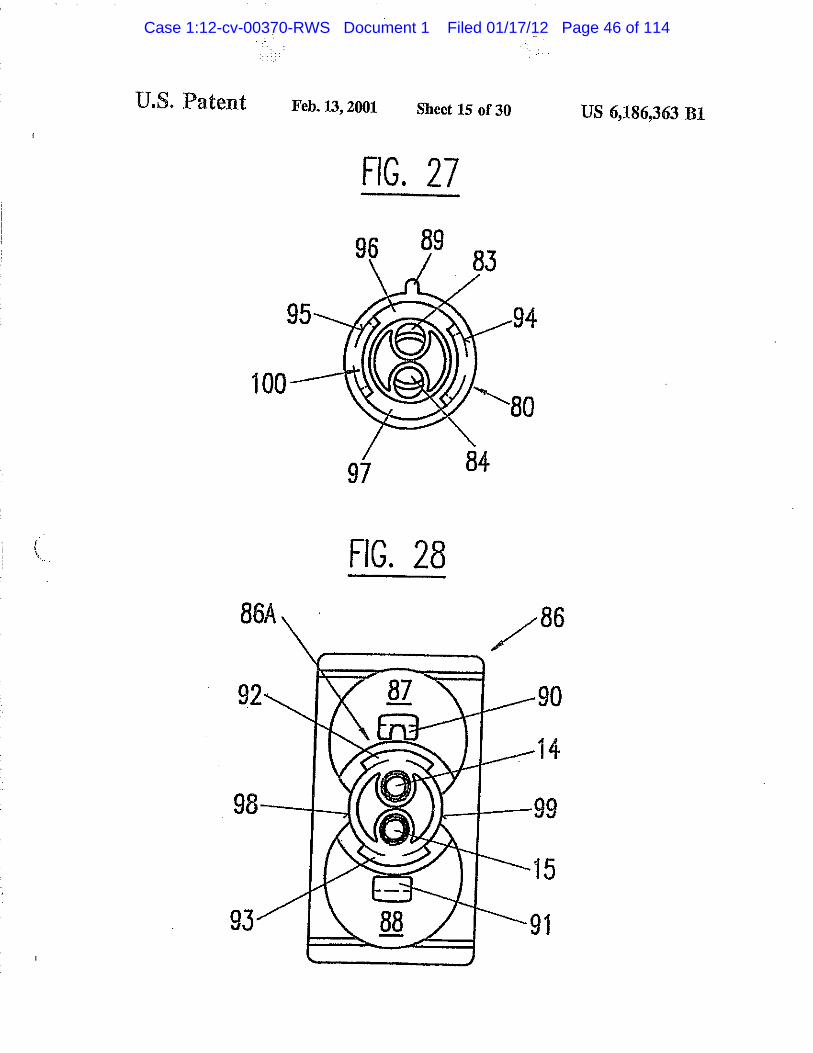
FIG. 27
96 89
FIG. 28 86Á 86
Case 1:12-cv-00370-RWS Document 1 Filed 01/17/12 Page 46 of 114

LS, Patent Feb. 13,2001 Sheet 16 of 30 US 6,186,363 B1
FIG. 29
Case 1:12-cv-00370-RWS Document 1 Filed 01/17/12 Page 47 of 114

U. S. Patent Feb. 13,2001 Sheet 18 of 30 US 6,186,363 B1
FIG. 30
1 0 7 , 0 6
FIG. 31
Case 1:12-cv-00370-RWS Document 1 Filed 01/17/12 Page 48 of 114

U . S. Patent Feb. 13,2001 Sheet 18 of 30 US 6,186,363 B1
FIG.32 y
Case 1:12-cv-00370-RWS Document 1 Filed 01/17/12 Page 49 of 114

U . S . Patent Feb. 13,2001 Sheet 18 of 30 US 6,186,363 B1
FIG. 33
C FIG. 34
21 20
1 2 7
128 1 2 8
21 j t
1 2 4
18 1 7
1 9
16 1 2 5
1 2 3
Case 1:12-cv-00370-RWS Document 1 Filed 01/17/12 Page 50 of 114

U . S . P a t e n t Feb. 13,2001 Sheet 18 of 30 US 6,186,363 B1
FIG. 35
Case 1:12-cv-00370-RWS Document 1 Filed 01/17/12 Page 51 of 114

U. S. Patent Feb. 13,2001 Sheet 18 of 30 US 6,186,363 B1
FIG. 36
FIG. 37
136A 133 152
Case 1:12-cv-00370-RWS Document 1 Filed 01/17/12 Page 52 of 114

U. S. Patent Feb. 13,2001 Sheet 18 of 30 US 6,186,363 B1
FIG. 38
Case 1:12-cv-00370-RWS Document 1 Filed 01/17/12 Page 53 of 114

U . S . Patent Feb. 13,2001 Sheet 18 of 30 US 6,186,363 B1
FIG. 39
17QA 1 7 0
FIG. 40 157 194
167A 195 158 192
Case 1:12-cv-00370-RWS Document 1 Filed 01/17/12 Page 54 of 114

U. S. Patent Feb. 13,2001 Sheet 18 of 30 US 6,186,363 B1
FIG. 41
157B 158B
FIG. 42
160A ® — 1 6 1 A
FIG. 43
194A
160A
195A 192A
Case 1:12-cv-00370-RWS Document 1 Filed 01/17/12 Page 55 of 114

U. S . P a t e n t Feb. 13,2001 Sheet 18 of 30 US 6,186,363 B1
FIG. 44
162A
Case 1:12-cv-00370-RWS Document 1 Filed 01/17/12 Page 56 of 114

I U.S. Patent Feb. 13,2001 Sheet 26 of 30 US 6,186,363 B1
FIG. 45
Case 1:12-cv-00370-RWS Document 1 Filed 01/17/12 Page 57 of 114

U . S . Patent Feb. 13,2001 Sheet 27 of 30
FIG. 46
190 19QA
191A 191
FIG. 47
179A 181 152
180A
Case 1:12-cv-00370-RWS Document 1 Filed 01/17/12 Page 58 of 114

U. S. Patent Feb. 13,2001 Sheet 18 of 30 US 6,186,363 B1
FIG. 48 169 193 169A
17QA 170
FIG. 5Q
1 6 7 A 1 5 8 192 195
215
1 5 K k 2 1 6
2 1 6 " " - 1 6 0
161 157 194 167
FIG. 49
Case 1:12-cv-00370-RWS Document 1 Filed 01/17/12 Page 59 of 114

U. S. Patent Feb. 13,2001 Sheet 18 of 30 US 6,186,363 B1
FIG. 51 FIG. 52
FIG. 53 FIG. 54
FIG. 55 FIG. 56
Case 1:12-cv-00370-RWS Document 1 Filed 01/17/12 Page 60 of 114

U. S. Patent Feb. 13,2001 Sheet 18 of 30 US 6,186,363 B1
FIG. 57 FIG. 58
Case 1:12-cv-00370-RWS Document 1 Filed 01/17/12 Page 61 of 114

US 6, 9 10
BAYONET FASTENING DEVICE FOR THE ATTACHMENT OF AN ACCESSORY TO A
MULTIPLE COMPONENT CARTRIDGE OR DISPENSING DEVICE
CROSS-REFERENCE TO RELATED APPLICATIONS
The present application is a continuation of patent appli-cation Ser. No. 08/563,109, aied Nov. 27,1995, now U.S. Pat. No. 5,918.772, which is a continuation in part of patent application Ser. No. 08/403,172 filed Mar. 13. 1995, now abandoned, and a continuation in part of patent application Ser. No. 08/522,109 filed Aug. 31, 1995 now abandoned.
BACKGROUND OF THE INVENTION The present invention relates to a bayonet fastening
device for the attachment of an accessory to a dispensing device, in particular for the attachment of a mixer to a iwo coraponenf cartridge.
There exists a great number of mixers and cartridges having means for attaching the mixer to the cartridge for example. U.S. Pat. Nos. 4,767,026 and 4,538,920 disclose on mixer that has two bayonet locking lugs inserted into corresponding prongs on the cartridge by rotation. On one hand, the rotary locking movement of the complete mixer will cause contamination of one chemical component against the other chemical component at ihe interface between the cartridge and the mixer, in that these compo-nents will be transported from one outlet to the other outlet, 3Q from one inlet to the other inlet, causing an undesired reaction between these chemical components at the interface between cartridge and mixer or closure means, and eventu-ally carrying such a reaction back into the cartridge outlets, thus causing plugging of the outlets. On the other hand there J5 exist situations where it is necessary to connect and attach the mixer or accessory to a multiple component cartridge or dispensing device in a predetermined position, such as when cartridge outlets or mixer inlets are of a different size for different relative mixing ratios or when mixers or accesso-ries are refitted for reuse.
There exists a need to connect and attach a mixer or accessory to a multiple component cartridge or dispensing device in a predetermined orientation, such as when car-tridge outlets or mixer inlets are of a different size for 45 different relative mixing ratios or when special high ratio mixers are used for greater mixing efficiency and when mixers or accessories are refitted for reuse. In the latter case of reuse, it is necessary to avoid any possibility of cross contamination of one chemical component against another 50 during refitting. Such cross contamination of reactive chemi-cal systems can cause plugging at the cartridge outlets and cause a reaction back into and within the cartridge.
U.S. Pat. No. 5,228,599 discloses a multiple dispensing cartridge having a mixer attached thereto with the aid of a coupling nut having an internal thread, wherein each storage cylinder ends in a dispensing opening which forms a side by side outlet, whereas the inlet of the mixer is not defined. The mixer is put on the cartridge and secured by a coupling nut via an external thread at the cartridge.
Another cross contamination situation can occur when a clean mixer or accessory inlet area or closure plugs are able to make any form of incorrect alignment contact, such as by angular tipping, with the chemical components at the car-tridge outlet area during the process of initial placing of the 65 mixer or closure plugs against the cartridge in preparation for attachment, in that case, when fitting the same mixer or
186 ,363 B1 closure plugs in the correct position, it is possible to now chemically contaminate the outlets of the cartridge. Again, this can cause plugging and a reaction back into and within the cartridge.
5 Additionally, it is commonly found in bayonet attachment means of the prior art that the bayonet prongs of the cartridge are relatively small and therefore of limited struc-tural rigidity and strength. This allows the possibility of distortion and is of greater significance due to the trend
10 towards smaller mixer diameters and therefore high backpressures, the result being leakage at the mixer to cartridge sealing interface during dispensing.
SUMMARY OF THE INVENTION On the basis of this prior art, it is an object of the present
invention to provide for a bayonet attachment device for attaching a mixer, or closure means or any other accessory, such as an adapter or a connecting tube to a multiple component dispensing device, in particular a two component cartridge, which has improved strength and structural rigid-ity against stress caused by greater hydraulic forces due to the trend towards smaller mixer diameters as well as pro-viding improved interface sealing.
This object is attained with a device wherein said bayonet attachment means at the dispensing apparatus or cartridge is formed as ring-shaped bayonet socket, with at least two internal recesses or art inner circular groove with at least two bayonet cutout followed by adjacent bayonet retaining means, and wherein the bayonet attachment means of the accessory comprises at least two bayonet lugs corresponding to the cut outs.
if is another object of the invention that alignment of the accessory inlets to the cartridge outlets takes place in one position only to avoid cross contamination. This object is attained with a device wherein said bayonet attachment means at the dispensing apparatus or cartridge and at (he accessory have means for coded alignment of the accessory to the dispensing apparatus or cartridge.
Other objects and improvements of the device are defined in the dependent claims.
BRIEF DESCRIPTION OF THE DRAWINGS The invention will be explained in more detail hereinafter
with reference to a drawing of embodiments. FIGS. 1-6 show a first embodiment of the invention with
a rotatable mixer housing, wherein FIG. 1 is a longitudinal section of a mixer, FIG. 2 is a view of the inlet end of the mixer, FIG. 3 is a longitudinal section of a cartridge, FIG. 4 is a top view of the cartridge of FIG. 3 with
distanced outlets and ring-shaped bayonet means, 55 FIG. 5 is a longitudinal section of a cartridge having two
containers with different cross-sectional areas, FIG. 6 is a top view of the cartridge of FIG. 5 with
distanced outlets and ring-shaped bayonet means. FIGS. 7—13 show a second embodiment of the invention
comprising a coupling ring, wherein FIG. 7 is a longitudinal section of a mixer, FIG. 8 is a view of the inlet end of the mixer, FIG. 8a is a view of an inlet end of the mixer according
to an embodiment in which the inlets have different sizes, FIG. P is a longitudinal section of a cartridge with
distanced outlets and ring-shaped bayonet means,
Case 1:12-cv-00370-RWS Document 1 Filed 01/17/12 Page 62 of 114

US 6,186,363 B1 3 4
FIG. 9a is a detailed view of a cartridge with distanced FIG. 37 is a view of the inlet end of the mixer, outieis of different size, F I G S 3 8_40 s h o w a n a]{eniaiive embodimenl of the
FIG. 10 is a top view of the cartridge of FIG. 9 with a nose invention with a sector-shapcd bayonet socket at the piece, cartridge, wherein
FIG. 11 is a top view of a coupling ring, 5 FIG. 38 is 3 longitudinal section of a mixer attached to a FIG. 12 is a section of the coupling ring of FIG. 11, partially shown cartridge, FIG. 13 is a longitudinal section of a variant of the mixer FIG. 39 is a top view of the cartridge of FIG. 38, and
of FIG. 7 and 8 attached to the cartridge of FIGS. 5 and 6 FIG. 40 is a view of the inlet end of the mixer, having containers with different cross-sectional area. 10 p i G S . 41-44 show a further embodiment of the invention
FIGS. 14-19 show a third embodiment of the invention with a coupling ring, wherein with a locking ring permanently attached to the cartridge, FIG. 41 is a longitudinal section of a mixer, wherein FIG. 42 is a longitudinal section of a coupling ring, disSaced4oÍletel0ngÍtUdÍnaI * * * * * ' ^ ^ ^ 15 FIG-43 is a top view of the coupling ring of FIG. 42, and
n T l s T s I top view of the cartridge of FIG. 14, F1<?' * * 1 ^ ^ o f th* ^ a t U c h e d F 6 a partially shown cartridge via the coupling ring.
FIG. 16A is J view on the mixer side of a locking ring to H G S . 4 5_47 s h o w a ¡ ^ embodiment of the invention be attacked to me cartridge. with a sector-shaped bayonet socket at the mixer, wherein • H G ; ¿ 5 ? f / / i e w 0 Q t h e cartr idSe s i d e o f locJdnS 20 FIG. 45 is a longitudinal section of a mixer attached to a
ring ot FIG. 16A, partially shown cartridge,
v H ™ T 7 v a , m C t £ £ f Í L 1 0 ^ ^ aCC°rd ing ÍO t h e HO. 46 is a top view of the cartridge of FIG. 41, and line XVII—XVII of FIG. 16B. . . - . . , , %.. , , . „„ FIG. 47 is a view of the inlet end of the mixer. FlGS. 18 and 19 show in two longitudinal sections at 90 c o , , £ .. . ,
to each other a mixer attached to the cartridge of FIG. 14 * f , R G S \ 4 ^ 5 8 show several further coding means at hoth with the locking ring of FIGS. 16A-17, & the locked the cartridge and the mixer for preventing cross-
. . contamination by erroneous attachment of the mixer onio the cartridge, wherein FIGS. 20-25 show three embodiments of a closure cap for piQ. 48 is a top view of a cartridge like in FIG. 39. with
the cartridge, wherein ^ c o d i D / r a e a n s >
FIGS. 20-21 show as first embodiment a two part closure H G 4 9 i s a s e c [ i o n o f [fae ^ e n d o f a m i x e r 1¡ke ^ m G cap in a longitudinal section and a view on Us cartridge side 3 g ^ a d d i j i o n a j c o d i n g meaDS>
„ „ „„ , , FIG. 50 is a view of the inlet end of the mixer of FIG. 49. FIGS. 22-23 show as second embodiment a one part „ , „ , . , .. ... , p r - . . .. j- . FIGS. 51 and 52 show a variant of the coding means at the closure cap for use with a coupling ring in a longitudinal 35 ^ . 6
section and a view on its cartridge side face. C n a o raiXer' r « « . . , . . . , , , FIGS. 53 and 54 show a further variant of the coding FIGS. 24-25 show as third embodiment a one part closure „ ,„ , ,„ t. „ „ . •. . „,„• , - ... . . . . .„ , j . r „ , , means at the cartridge and mixer, cap for use with a locking ring attached to the cartndge in „ , , „ , . .. ,
a longitudinal section and a view on its cartridge side face. F I G S - a n d » s h ™ a f u r t h e r v a n a n l o t the c o d l nS ^. „ „ , _ . . . . ^ _ , An means at the cartndge and mixer. FIGS. 26-28 show an alternative embodiment of the 40 , , _ ,, . , r invention with a ring-shaped bayonet socket at the rotatable F I G S" S ? a n d 5* s h ™ a ^ t h e r v a n a D t o f the c o d i n g
mixer housing, wherein m e a n s a l t h e c a r t n dS e a n d m i x e r-FIG. 26 is a longitudinal section of a mixer attached to a DETAILED DESCRIPTION OF THE
partially shown cartridge, PREFERRED EMBODIMENTS FIG. 27 is a view of the inlet end of the mixer, and * H G S < t _ 2 s h o w a raixer 1 comprising a mixer housing 2, FIG. 28 is a top view of the cartridge of KG. 26. a mixer element group 3, the mixer outlet 4 and a mixer inlet FIGS. 29-31 show a further embodiment of the invention section 5 with two separated inlet parts 6 and 7, which are
with a ring-shaped bayonet socket at the cartridge, wherein integral with a properly aligned separating element 3S of the FIG, 29 is a longitudinal section of a mixer attached to a » raixer element group 3. This mixer is attached to the
partially shown cartridge, cartridge by matching the mixer different width bayonet lugs . . c J • 1 , _ j r . . 10, 11 to the different width bayonet sockets 19, 20 while FIG. 30 is a view of the inlet end of the mixer, and ,, . , * , , ' . ,, pressing the mixer onto the cartndge and by rotating the
FIG. 31 is a top view of the cartridge of FIG. 29. m i x e r h o u s i n g 2 . The separated inlet parts 6 and 7 and the FIGS. 32-34 show a further embodiment of the invention 55 mixer element group 3 with the separating element 3S do not
with a ring-shaped bayonet socket at the cartridge, wherein rotate. Separating element 3S serving in this embodiment as FIG. 32 is a longitudinal section of a mixer attached to a a separating means for guiding each chemical component
partially shown cartridge, separately to the first dividing element 3D of the mixer FIG. 33 is a view of the inlet end of the mixer, and element group 3. FIG. 34 is a top view of the cartridge of FIG. 32. 60 , T h e m i x e / * provided with longitudinal ribs 8
^ , . ,, . . . x „ „ . that end at the larger diameter 9 of the mixer housing 2. The FIGS. 35-37 show an further embodiment of the inven- ^ ]atera{ e n d s o f { h e ^ a r e f o r m e d ^ b a y o n d l u g s 1 0 a n d
lion with a sector-shaped bayonet socket at the cartndge, n c o o p e r a t i n g ^ íh the bayonet retaining means of the wnerein cartridge. As follows from FIG. 2, the two lugs do not have
FIG. 35 is a longitudinal section of a mixer attached to a 65 the same width, lug 10 being larger than lug 11. As will be partially shown cartridge, shown later, the different width of the lug^ enable a coded
FIG. 36 is a top view of the cartridge of FIG. 35, and alignment and attachment of the mixer to the cartridge.
Case 1:12-cv-00370-RWS Document 1 Filed 01/17/12 Page 63 of 114

US 6,186,363 B1 5 6
The mixer element group 3 is connected to the separated Cartridge 35 (see FIGS. 9 and 10) is the same as cartridge inlet parts 6 and 7 and is disposed in such a way within the 1 of FIG. 1 with the exception that the bottom of the bayonet housing that the housing itself is rotatable around the mixer attachment means 16 comprises a nose piece 36 correspond-element group 3 with attached inlet parts 6 and 7, which are ing to the slot 30 at the mixer (see FIGS. 7 and 8), for coded arranged at the inlet side of the first mixer element 3S 5 alignment of the mixer. serving in this embodiment as a separating means for When connecting the mixer to the cartridge, the nose guiding each component separately to the first dividing piece 36 on the cartridge fits into slot 30 of the mixer inlet element 3D of the mixer element group 3. section 27. This coded connection method assures not only
In FIG. 3, the cartridge 12 comprises two cylindrical «»alignment possibility but also axial mixer attachment containers or chamber 13 of equal cross-sectional areas for JO without rotation of the mixer housing thus preventing a 1:1 metering ratio ending in two individual, separate * ^ * cylindrical and distal outlets 14 and 15. The outside shapes ™ , , of the distal outlets 14 and 15 of the cartridge correspondto ^ T are ™ans possible at the d^ensing f, . , Cy. . ? , , , r , „ _ apparatus or cartridge and at the accessory for the coded die respective inside shapes of the separate inlets 6 and 7 of £ t o f tfae a c* t 0 the d i s p e n s 4 g appara tus o r the mixer, (see FIG 1) whereby the mlete of the mixer fit 15 c s t [ l i d p i n s Qr prodding parts of all kLd fitting into over the outlets of the cartndge for tightly sealed connec- a r e c e s s o r c a v i t y o r s l o t T h e c o d i n g m e a n s raay ^ l a k e tions. A reverse arrangement, where the inlet parts 6 and 7 the form of differently shaped, similar or dissimilar sized fit into the outlet openings 14 and 15 is also possible. inlets and outlets as described later in the specification.
In FIG. 4, the bayonet means 16 at the cartridge comprises FIG. 13 shows a mixer 38 attached to a cartridge 75 a ring-shaped bayonet socket 17 with two internal recesses 20 having containers 76 and 77 with different cross-sectional 18 and a circular opening with two diametrically opposed areas, as a variant to the embodiment shown in FIGS. 5-12 different width bayonet cutouts 19 and 20 for receiving the in that the mixer inlet section 37 of mixer 38 has a separating corresponding different width bayonet lugs 10 and 11, (see means within the mixer, which separating means comprises FIG. 1). of the mixer, allowing coded introduction of the separated inlet chambers 39, 40, respectively having diflfer-mixer in one predetermined position only. The flange parts 25 e n t cross-sectional areas, and lodged within a smaller com-21 adjacent to the cutouts serve as bayonet retaining means b i n e d diameter than the cartridge outlet with corresponding for securing the lugs of the mixer. openings for each chamber for material to pass through.
The ring-shaped bayonet means provides, in particular, ^aforementioned separating means serves to maintain for increased strength of the bayonet retaining means and «eparation of the material flows up to the first drnchng j . ^ , . 30 element 3D of the mixer element group 3. This separating increased structural rigidity of the outlet end of the cartndge ^ c a n hayf i c h a m b e r s w { l h *a ] when during dispensing, the hydraulic forces transmitted o r h a V e a c r o s s_ s e c l i o n a l a r c a ^ o t h e r thaQ 1 :1 . F o r from tfae attached mixer are at a maximum. This arrange- example, ^ ratio of the cross-sectional areas of the sepa-ment is a substantial improvement tn comparison with the rating chambers can be adapted to the cross-sectional areas prior art bayonet prongs. J5 0 f the containers 76 and 77 of cartridge 75, respectively to
FIGS. 5 and 6 show a variant to the embodiment shown * its metering ratio. The separating means is fixedly connected in FIGS. 1-4 in that the containers 22 and 23 of cartridge 24 to the mixer element group 3. have different cross-sectional areas for metering ratios other The cartridge 75 has the same attaching means as in FIGS, than 1:1. 5 and 6, and the mixer 38 is attached to the cartridge by
In both described cases, in order to attach the mixer to the 40 means of the coupling ring 31. cartridge, the mixer can only be aligned with its bayonet lug The third embodiment of the invention according to the widths corresponding to the different width cut outs of the FIGS. 14-19 comprises a locking ring 51 that is snapped bayonet sockets* then pressed onto the cartridge such that onto and permanently attached to the cartridge 42. The when the mixer is in place and the outlets and inlets are cartridge 42 comprises two cylindrical containers or cham-connected, the mixer housing 2 is rotated by 90° for the 45 bers 43 of equal cross-sectional area, two distal outlcis 45 engagement of the bayonet lugs 10, 11 in the bayonet and 46, and an attaching means 47 for attaching the locking retaining means 21 of the cartridge. This attachment method ring 51 and for limiting its rotational movement. The form prevents con lamination of one component by the other at the 0 f the attaching means 47 is a circular edge 49 with two lugs mixer-cartridge interface yet enabling a quick coded attach- 44 Df same width and arranged around the two distal outlets ment of the mixer. 50 with a circular undercut 48 at its base.
FIGS. 7 and 8 show in a second embodiment a mixer 25 The locking ring 51 (see FIGS. 16A and 16B) and 17, comprising a mixer housing 26, a mixer element group 3, a snaps over circular edge 49 of the attaching means of the mixer outlet 4, and a mixer inlet section 27. This mixer is cartridge and remains attached to it. The locking ring 51 has fixed to the cartridge 35 (see FIG. 9) with the aid of a an inner circular groove 52 forming a cartridge side edge 53 separate coupling ring (see FIGS. 11 and 12). The coupling 55 and a mixer side edge 54. The cartridge side edge 53 has two ring 31 is provided with two bayonet lugs 32 and 33 opposed cutouts 55 the width of which corresponds to the corresponding to the bayonet cutouts 19,20, respectively of lugs 44 of the attaching, means whereby the inner diameter the b ayonel attachment means 16 at the cartridge. For better 0 f the cartridge side edge 53 is slightly smaller than the outer manual gripping, ribs 34 are provided on the outer cylin- diameter of the circular edge 49 of the attaching means of drical surface. 60 the cartridge. For snapping the locking ring to the cartridge,
It follows in particular from FIG. 7 that the mixer inlet the ring is positioned so that the cutouts of its cartridge side section 27 comprises two cylindrical, individual inlet open- edge are placed above the lugs of the attaching means and ings 28, 29 at the inlet side face of the first mixer element the ring is then pushed onto the cartridge so that the 3S serving in this embodiment as a separating means for remaining cartridge side edge of the locking ring slides into guiding each component separately to the first dividing 65 the circular undercut 48 of the attaching means. The locking element 3D of the mixer element group 3. Aslot 30 provides ring is also provided with a serration 58 for better manual for a coded alignment of the mixer in regard to a cartridge. gripping.
Case 1:12-cv-00370-RWS Document 1 Filed 01/17/12 Page 64 of 114

US 6,186 ,363 B1 9 10
The mixer side edge 54 has two opposite cutouts 56 and In the case of utilizing the advantages of the ring-shaped 57 of different width corresponding to the lugs 10 and JUL of bayonet socket alone and without the need for coded the mixer for insertion in one position only. These two attachment, the bayonet lugs 10 and 11,32 and 33. 64 and cutouts are arranged at 90° to the cutouts 55 of the cartridge 65 at the mixer or closure cap or accessory as well as the side edge. Thus, when the mixer 59 is to be attached to the 5 corresponding bayonet cutouts 19 and 20 at the retaining locking ring on the cartridge and the locking ring is rotated means at the cartridge or 56 and 57 af the locking ring 51, by 90°, the remaining inside flange parts of both the car- may have the same widths. This applies also in the case iridge side edge and the mixer side edge serve as bayonet when more than two lugs and corresponding cutouts are retaining means to encompass the mixer lugs 10 and 11 as used, for example three or four respectively, well as the lugs 44 of the attaching means 47 of the cartridge (Q The FIGS. 26-28 show a further embodiment of the for strong securement. invention with an inverse bayonet arrangement as compared
FIGS. 18 and 19 show cartridge 42 of FIG. 14 with a with those of the bayonet arrangement of the mixer and mixer 59, which is similar to mixer 1 of FIG. 1 with the same cartridge according to FIGS. 1-4. FIG. 26 shows a mixer 80 mixer inlet section 5 with separate female inlets 6 and 7, comprising a mixer housing 81 with mixer outlet 4 and a except thai the housing 60 is not rotatable around the integral mixer inlet section 82 containing two separa ted inlet parts 83 internal parts of the mixer and has no ribs 8, and the two 15 and 84 followed by a separating element 3S, which in turn bayonet lugs 10 and 11 are of different widths. FIG. 18 is fixedly attached to a properly aligned element 3D of the shows the mixer introduced within the locking ring 51 with mixer element group 3. Also this mixer is attached to the the locking ring in its locked position and FIG. 19 shows a cartridge by matching the coding means of mixer and section along the line XIX—XIX in FIG. 18 of the same ^ cartridge by pressing the mixer onto the cartridge and by assembly at 90°. It is evident that a mixer with separated 20 rotating the mixer housing 81 of the mixer about ihe integral inlet chambers can be attached likewise and also that a internal mixer parts comprising separate female inlets 83 cartridge may be one having containers with different cross- a n d 84< t h e separating element 3S and the mixer element sectional areas as m FIG. 5. group 3. The mixer element group or part thereof could also
The above described system of the coded attachment of be prealigned and be fixedly assembled within the mixer the mixer also allows for the coded attachment of closure 25 housing. caps, adapters etc:., thus preventing cross contamination and The mixer housing 81 is provided with longitudinal ribs allowing closure cap re-use. 8, which end at the larger diameter 85. The larger end of the
The first embodiment of a coded closure cap 61, FIGS. 20 mixer housing has a nose piece 89, which provides a highly and 21, consists of two pans. The insert 62 has two male visible coded guide for alignment and insertion into the plugs 63 for closing the outlets of a cartridge, for example slotted prong 90 of the cartridge. The mixer housing 81 is the distanced outlets 14 and 15 of cartridge 12 of FIG. 3. also provided with a ring shaped bayonet socket attachment
In this embodiment it is shown how the sealing effect of means 100 comprising two bayonet flange parts 94 and 95 a plug at the cartridge outlet can be improved by providing acting as bayonet retaining means, having two cut outs 96 the male plug 63 with a second rim 63A reaching over the ^ and 97 in between. female cartridge outlet. The provision of such a male plug ~ The cartridge 86 has two cylindrical containers 87 and 88 with a circumferential rim is of course not limited to this with the distanced outlets 14 and 15 for fitting and scaling example. within the mixer inlet section 82. The cartridge front 86A is
The rotatable attaching means has two bayonet lugs 64 provided with a slotted prong 90 and a guide piece 91 for and 65 of different widths corresponding to the lugs 10 and ^ preventing incorrect insertion of the mixer and further with 11 of mixer 1 of FIG. 1. The outer surface of the cap is two bayonet flanges 92 and 93 with tapered wedge shaped provided with ribs 66 and a collar 70 for better gripping. The edges, corresponding in width with the mixer cutouts 96 and coded attachment of the closure cap to cartridge 12 or 24 is 97. and with reduced diameter cutouts 98 and 99 in between, analogous to the attachment of mixer 1. p0r attaching the mixer to the cartridge, the mixer inlet
The second embodiment, FIGS. 22 and 23, consists of a 45 part 82 is introduced into the cartridge by aligning the nose coded closure cap 67, which also has two plugs 68 for piece 89 of the mixer housing within the slotted prong 90 closing the outlets of a cartridge, for example the distanced while the part 91 acts as a guide piece as the mixer inlets are male outlets 14 and 15 of cartridge 35 of FIG. 9, and a slot pushed onto and over the cartridge distanced male outlets 14 69 similar to slot 30 at mixer 25 for coded cooperation with and 15 such that the cartridge flanges 92 and 93 correspond nose piece 36 of cartridge 35. The outer surface of the cap 50 to and enter within the mixer cutouts 96 and 97. Upon is also provided with a collar 70 for better manual gripping. rotating the mixer housing, the mixer bayonet flange parts 94 The attachment of the cap to cartridge 35 is achieved with and 95 progressively move against the cartridge flanges 92 coupling ring 31 of FIG. 11, analogous to the attachment of and 93, because of their tapered wedge shaped depth, mixer 25 to that cartridge. forcing the mixer 80 against the cartridge front 86A. During
The third embodiment of a coded closure cap 71, FIGS. 55 this mixer to cartridge attachment, the mixer housing 81 24 and 25, is similar to the second embodiment and com- rotates 90° about the stationary integral internal mixer parts, prises two plugs 72 for closing the distanced male outlets 45 The above bayonet arrangement, wherein the ring-shaped and 46 of cartridge 42 of FIG. 14. FIG. 25 shows the bayonet socket is at the accessory, as shown for a rotating cartridge side of the closure cap with two bayonet lugs 73, mixer housing, can also be used in analogous manner for 74 of different width and diametrically opposed on the edge go previously shown embodiments and for the closure caps, facing the cartridge. This closure cap is attached by means with the exception of the locking ring solutions. Alternative of the locking ring 51 of FIGS. 18 and 19 and is also coding means arranged around the outer periphery of the provided with a collar 70 for better manual gripping. mixer housing are possible or is achieved by different widths
The ring-shaped bayonet attachment means of the car- of cutouts and matching flange parts, tridge ensures a better stability of its outlet area and stronger 65 FIGS. 29-31 show a further embodiment wherein the retaining of the bayonet lugs compared with prior art bayo- mixer is provided with male inlet parts fitting into and net aitachment means. sealing within the female cartridge outlets.
Case 1:12-cv-00370-RWS Document 1 Filed 01/17/12 Page 65 of 114

US 6,186 9
FIG. 29 shows a mixer 101 comprising a mixer housing 102 with mixer outlel 4 and a mixer inlet section 103 containing two separate male inlets 104 and 105 followed by a separating element 3S which in turn is fixedly attached to a properly aligned first dividing element 3D of the mixer 5 element group 3. Also this mixer is attached to the cartridge by matching the coding means of the mixer to the coding means of the cartridge, by pressing the mixer onto the cartridge and by rotating the mixer housing 102 about the integral interna] mixer parts comprising separate male inlets 10 104 and 105, the separating element 3S and the mixer element group 3. The mixer element group or part thereof could also be prealigned and be fixedly assembled within the mixer housing.
The mixer housing 102 is provided with longitudinal ribs 8, which end at the larger diameter 106. the two lateral ends of which are formed as bayonet lugs 107 and 108, FIG. 30, cooperating with the bayonet retaining means of the car-tridge. The bayonet lugs do not have the same width. lug 107 being larger. 20
The cartridge 109, FIG. 31, has rwo cylindrical containers 110 and 111 with the distanced female outlets 112 and 113 for fitting and sealing over the male mixer inlets 104 and 105. The cartridge front 114 is provided with the same bayonet means 16 as the cartridge of FIG. 4, comprising a 25
ring shaped bayonet socket. FIGS. 32-34 show a further embodiment wherein the
mixer is provided with a male and a female inlet part fitting and sealing into/over the female/male cartridge outlets.
FIG. 32 shows a mixer 115 comprising a mixer housing 116 with outlel 4 and a mixer inlel section 117 containing a separate male inlet 118 and a separate female inlet 119 followed by separated chambers 117A and 117B, which in turn are fixedly attached to a properly aligned first dividing 35 element 3D of the mixer element group 3. Also this mixer is attached to the cartridge by pressing the mixer onto the cartridge and by rotating the mixer housing 116 about the integral internal mixer parts comprising separate male inlets 118 and 119, the separated chambers 117Aand 117B and the 4Q mixer element group 3. The mixer element group or part ihereof could also be prealigned and be fixedly assembled within the mixer housing.
The mixer housing 116 is provided with longitudinal ribs 8, which end at the larger diameter 120, the two lateral ends 45 of which are formed as bayonet lugs 121 and 122, FIG. 33, cooperating with the bayonet retaining meaDS of the car-tridge. The bayonet lugs do not have the same width, bayonet lug 121 beiag larger.
The cartridge 123 has two cylindrical containers 124 and 50 125 with one distanced male outlet 126 and one distanced female outlet 127 for, respectively, fitting and sealing within the separate female inlet 119 and over the separate male inlet 118 of the mixer. The cartridge front 128, FIG. 34, is provided with the same bayonet means 16 as the cartridge of 55 FIG, 4, comprising a ring shaped bayonet socket.
The embodiments of FIGS. 35-43 show sector-shaped bayonet sockets instead of complete ring-shaped ones. The function and the attaching of the accessory are the same as in the previous embodiments, so that the three different go embodiments of the bayonet means are illustrated in one respective example of mixer and cartridge. It is obvious that the sector-shaped bayonet socket and similar means can be provided on all other embodiments also.
FIG. 35 shows a mixer-cartridge assembly with a mixer 65 130 comprising a mixer housing 131 with outlet 4 and a mixer inlet section 132 containing two separate male inlets
,363 B1 10
133 and 134 followed by separating chambers 133A and 134A which in turn are fixedly attached to a properly aligned first dividing element 3D of the mixer element group 3. Also this mixer is attached to the cartridge by pressing the mixer onto the cartridge and by rotating the mixer housing 131 about the integral internal mixer parts comprising separate male inlets 133 and 134, the separated chambers 133A and 134A and the mixer element group 3. The mixer element group or part thereof could also be prealigned and be fixedly assembled within the mixer housing.
The mixer housing 131 is provided with longitudinal ribs 8, which end at the larger diameter 135, the two lateral ends of which are formed as bayonet lugs 136 and 137, FIG. 37, cooperating with the sector-shaped bayonet sockets 145, 146, serving as bayonet retaining means of the cartridge. The bayonet lugs have the same width and are provided each with a rib 136Aand 137A at it's end which both strengthen each lug and acts as a stop as well as ensuring that the mixer can be turned and attached in one direction only. The upper surface of the lugs may have inclined surface parts so as to enforce the locking ability by an axial load. Corresponding inclined surface parts may also be located on the corre-sponding surface of the cartridge sector shaped bayonet sockets.
The cartridge 138 has two cylindrical containers 139 and 140 with two distanced female outlets 141 and 142 for receiving and sealing over the separate male inlets 133 and 134. The cartridge front 143, FIG. 36, is provided with bayonet means comprising sector-shaped bayonet sockets 145,146 which act as prongs and are closed on one side by a rib 145A and 146A which connects to the cartridge end wall so as to stiffen and increase (he strength of the bayonet prong. The cutouts 149 and 150 between the sector shaped bayonet sockets allow for the introduction of the mixer bayonet lugs 136 and 137.
In this embodiment the bayonet lugs and the sector shaped bayonet sockets have approximately the same width. The coding is achieved by other coding means on the mixer and on the cartridge. The cartridge front 143 is provided with a T-shaped protrusion 151 arranged between the two outlets and the mixer inlet face is provided with a similar protrusion 152 arranged off center between the mixer inlets, see FIGS. 36 and 37.
The two T-shaped coding means allow the attachment of the mixer in one orientation only since, when putting the mixer onto the cartridge such that when the two protrusions are laying one upon the other, they will prevent the intro-duction of the mixer inlets into the cartridge outlets and also any contact between the cartridge outlets and the mixer inlets or plugs of closure means thus preventing cross contamination and prohibiting mixer/accessory attachment. It is obvious that the coding protrusions can have any shape other than a T-form, and could be e.g., in the form of a keyway allowing only one defined position in which to introduce the mixer having a corresponding protrusion, or two differently shaped keyways and corresponding protru-sions.
The coded alignment can be facilitated by visual coding means, e.g., a marking 153 at the cartridge outlet end and a marking 154 at the bayonet lug 137 of the mixer on the same side as the coding protrusion.
In the embodiment of FIGS. 38-40, the coding is achieved by cutouts of different widths between the lugs. FIG. 38 shows a mixer-cartridge assembly with a mixer 155 with a mixer housing 156, outlet 4 and integral internal mixer parts comprising two separate inlets 157 and 158
Case 1:12-cv-00370-RWS Document 1 Filed 01/17/12 Page 66 of 114

US 6,186 ,363 B1 9 10
ending into a disc-shaped flange and followed by separated must be large enough to fit over the larger retaining means chambers 157Aand 158 A which in turn are fixedly attached of the cartridge, whereas the visual coding means rest the to a properly aligned first dividing element 3D of the mixer same as previously described. element group 3. Also this mixer is attached to the cartridge FIGS. 41-44 show a similar arrangement to that of the by pressing the mixer onto the cartridge and by rotating the 5 FIGS. 38-40 except that the mixer 200 is separate from mixer housing 156 about the integral internal mixer parts. coupling ring 196, the latter being rotated about the station-The mixer element group 3 or part thereof, may also be a ry mixer during the final rotary locking attachment of the prealigned and fixedly assembled within the mixer housing. coupling ring bayonet lugs 160A. 161A. into the sector
The mixer housing 156 is provided with longitudinal ribs shaped bayonet sockets 169. 170 of the cartridge 162. 8. which end at the larger diameter 159, the two lateral ends ™ FIG. 41 shows mixer 200 with the outlet 4 and comprising of which are formed as bayonet lugs 160 and 161, FIG. 40, a housing 201 containing the mixer element group 3 in cooperating with the sector shaped bayonet retaining means alignment with inlet part 197, the latter only partially of the cartridge. In this FIG. 38 and also in FIGS. 13,32.35 contained within the mixer housing and comprising separate and 45 it is shown that the inlet end of the mixer housing has male inlets 157B. 158B and separate chambers 157C, 158C. not only one cylindrical enlargement but two. e.g., one 159 " A ^dge 198 lodges and seals the inlet part 197 within the at the inlet, lodging and sealing against the separate inlets mixer housing. The coupling ring 196 is preassembled and 157, 158, followed by the second pari 159A having an prealigned with the mixer inlet part 197 via a groove 199. intermediate diameter and lodging and sealing against the FIG, 41. in the coupling ring 196. FIG. 43 shows coupling separating means 157A, 158A. The bayonet lugs have the ring X96 with the same coded bayonet Ings 160A, 161 A, cut same widths but the gaps or cuiouts 194,195 between them 20 o u t s £94A, 195A. visual coding 154 and V-shape nose are different, corresponding to the different widths of the coding 192A as used in the embodiment according to FIG. sector shaped bayonet sockets on the cartridge. 40.
These bayonet lugs 160,161. can be provided each with FIG. 44 shows the mixer 200 and the cartridge 162 when a rib 167, FIG. 40, on the reverse side of the mixer inlet ^ assembled together. Prior to such assembly, the coupling which both strengthen the lug and act as stop as well as 25 ring 196 may be pre-assembled to the mixer under sufficient limiting rotation in one direction only so as to prevent the tension such that both components are held together in the mixer from being attached at 180° to the correct alignment. correct relative alignment for initial visual coded and initial The upper surface of the lugs may have inclined parts, not axial mechanical coded contact and attachment of the mixer shown, so as to enforce the locking and sealing ability by an inlets 157B, 158B to the cartridge outlets 165, 166 on the axial force. Corresponding inclined pans, not shown, may 30 cartridge prior to the final rotary locking attachment of the also be located on the corresponding surface of the cartridge coupling ring as described above. In this embodiment sector shaped bayonet sockets. therefore, there is no rotation of the mixer housing 201 aboui
The cartridge 162 has two cylindrical containers 163 and the mixer inlet part 197 and element group 3 during attach-164 with two distanced female outlets 165 and 166 for ment, receiving and sealing over the separate male inlets 157 and 35 In the embodiment according to FIGS. 45-47 the sector-158. The cartridge front 168, FIG. 39, is provided with shaped bayonet sockets are at the mixer and the bayonet lugs bayonet means, comprising two scctor-shaped bayonet sock- at the cartridge, in analogy to the embodiment according to ets. FIGS. 26-28.
In FIG. 39, the bayonet means at the cartridge comprises 4Q FIG. 44 shows a mixer-cartridge assembly with a mixer two diametrically opposed sector-shaped bayonet sockets 173 comprising a mixer housing 174 with outlet 4 and a 169 and 170 acting as bayonet prongs for the bayonet lugs mixer inlet section 175 containing the integral internal parts of the mixer, the two sockets having different widths, socket comprising two separate male inlets 176 and 177 followed 169 having the greater width. The two cut outs 171 and 172 by separated chambers 176A and 177A which in turn are between the sockets allow for the introduction of the cor- 4? fixedly attached to a properly aligned first dividing element responding mixer bayonet lugs 160 and 161 into the sector 3D of the mixer element group 3. Also this mixer is attached shaped bayonet sockets 169,170. As shown in this Figure, to the cartridge by pressing the mixer onto the cartridge and the passages of the bayonet sockets 169 and 170 commence by rotating the mixer housing 174 about the separate male as straight passages but become curved front the mid point inlets 176 and 177, the separated chambers 176A and 177A onwards so as to achieve a greater strength against bayonet 5Q and the mixer element group 3. The mixer element group or lug axial forces. part thereof could also be pre-aligned and be fixedly
The passages can be wholly curved, without straight parts, assembled within the mixer housing, and wholly or partly curved passages can also be provided The mixer housing 174 is provided with longitudinal ribs on the ring-shaped bayonet attachment means. 8, which end at the larger diameter 178, the two lateral ends
In order to prevent any inadvertent contact whatsoever of 55 of which are formed as two diametrically opposed sector-the mixer or accessory inlet or inlets with the cartridge outlet shaped bayonet sockets 179 and 180 (see FIG. 43) acting as or outlets by any form of tilting or tipping of one against the prongs which are both closed at one side by a rib 179 A and other during incorrect alignment the larger cut out 195 at the 180A connecting to the mixer wall so as to stiffen and mixer is provided with a V-shape nose 192 corresponding to increase the strength of the bayonet prong. The cut-outs 181 a V-shape incision 193 at the larger socket 169 such that the 60 and 182, between the sockets, allow for the introduction of mixer is kept outside of the narrower bayonet socket 170 by the cartridge bayonet lugs cooperating with the bayonet the V-shape nose 192. retaining means of the mixer.
In this embodiment also the coded alignment can be The cartridge 183 has two cylindrical containers 184 and facilitated by visual coding means, e.g., marking 153 at the 185 with two distanced female outlets 186 and .187 for fitting cartridge and marking 154 at the corresponding lug. <55 aad sealing over the separate male inlets 176 and 177. The
In case no univocal attachment of a mixer to the cartridge cartridge front 188, FIG. 42, is provided with bayonet 162 is necessary the cut outs between the lugs of the mixer means, comprising sector-shaped bayonet lugs 190 and 191
Case 1:12-cv-00370-RWS Document 1 Filed 01/17/12 Page 67 of 114

US 6,186 ,363 B1 9 10
having the same width and each being provided with a rib part thereof, may also be prealigned and fixedly assembled 190A and I9lAal it's end which strengthens the lug and act within the mixer housing. as a stop as well as limiting rotation in one direction only so The mixer housing 156 is provided with longitudinal ribs as to prevent the mixer from being attached at 180° to the 8, which end at the larger diameter 159, the two lateral ends correct alignment. The upper surface of the lugs may have 5 of which are formed as bayonet lugs 160 and 161 cooper-inclined surface parts, aoi shown, so as to enforce the a ting with the sector shaped bayonet retaining means of the locking ability by an axial load. Corresponding inclined cartridge. This mixer can also have two enlargement, e.g.. surface parts, not shown, may also be located on the corre- ?n e 1 5 9 ai inIet< lodging and sealing against the separate spocding surface of the mixer sector shaped bayonet sock- P l e t s I s?, 158, followed by the second part 1S9A having an eLS J0 intermediate diameter and lodging and sealing againsl the
i-p* 1 . tU , , , „ . „ . separating means 157A, 158A, The bayonet lugs have the The lugs and the cutouts have approximately the same s a ^ e wic£hs buf t h e s o r cu t o u l s 1 9 5 behveeo them width. Thus the required coding; is achieved byother coding are d i f feren£i ^ p o n d i n g to the different widths of the means on the mixer and on the cartridge. Therefore the s e c t o r s h a p e d bayonet sockets on the cartridge, and have cartridge front 188 is provided with the T-shaped protrusion ajg0 j bs. 151 arranged between the two distanced female outlets and « I a add i t i cm l o the roixer o f FK5 . 3 8 the k l e t p a r l o f this the mixer inlet race is provided with a similar shaped mixer 214 is provided with the same coding protrusions 215 protrusion 152 arranged off center between the mixer inlets. as those of the cartridge, consisting of two pins 216 and See FIGS. 46 and 47. arranged in accordance to the pins 213 of the cartridge such
The two T-shaped coding means allow the introduction of that the mixer can only be introduced the correct way with the mixer in one position only, since the placing of the mixer 20 regard to the other coding means without the possibility of onto the cartridge is such thai, when the two protrusions are tilting if introduced by force the wrong way. laying one upon the other, they will prevent the introduction The FIGS. 51-58 show further arrangement and forms of of the mixer separate male inlets into the cartridge distanced coding protrusions 212, 215. whereby the cartridge as well female outlets as well as any contact between the cartridge as the mixer are always the same as in FIGS. 48-50 and only outlets and the mixer inlets, thus prohibiting cross contami- 25 the coding protrusions are provided with numerals, the other nation and mixer/accessory attachment. It is obvious that the parts being the same. coding protrusions can have any shape other than aT-form. FIGS. 51 and 52 show a coding protrusions 212 on the
There are situations where the T-shaped coding protrusion cartridge front consisting of two bars 217 arranged sym-give not a 100% protection to warrant no cross- metrically to the transversal middle axis of the cartridge but contamination. FIGS. 48-58 show several coding asymmetrically lo (he axis connecting the centers of the protrusions, which are believed to warrant that no cross- outlets. The two bars 218 of the mixer inlet part are arranged contamination can occur even if the mixer is introduced onto in accordance to those of the cartridge such that introduction the cartridge in the wrong sense. To this end the coding and attachment of the mixer onto the cartridge is only protrusions are arranged thus that no tilting around the axis 35 possible in one position. connecting the centers of the two outlets of the cartridge, FIGS. 53 and 54 show a coding protrusions 212 on the which could cause this contamination. cartridge front consisting of two D-shaped protrusion 219
The cartridge 210 of FIG. 48 is similar to the cartridge 162 arranged symmetrically to the transversal middle axis of the of FIG. 39 and has the same two cylindrical containers with cartridge but asymmetrically to the axis connecting the two distanced female outlets 165 and 166 for receiving and 40 centers of the outlets, with both flat sides looking in one sealing over the separate male inlets 157 and 158. The direction. The two D-shaped protrusions 220 of the mixer cartridge front diametrically opposed sector-shaped bayonet inlet part are arranged in accordance to those of the cartridge sockets 169 and 170 acting as bayonet prongs for the such that introduction and attachment of the mixer onto the bayonet lugs of the mixer, the two sockets having different cartridge is only possible in one position, widths, socket 169 having the greater width. The two cutouts 45 FIGS. 55 and 56 show a coding protrusions 212 on the 171 and 172 between the sockets allow for the introduction cartridge front consisting of a male plug 221 and a female of the corresponding mixer bayonet lugs 160 and 161 into plug222 arranged symmetrically. The male plug 223 and the the sector shaped bayonet sockets 169,170. As shown in this female plug 224 of the mixer inlet part are arranged in Figure, the passages of the bayonet sockets 169 and 170 accordance to those of the cartridge such that introduction commence as straight passages but become curved from the SQ and attachment of the mixer onto the cartridge is only mid point onwards so as to achieve a greater strength against possible in one position. bayonet lug axial forces. FIGS. 57 and 58 show a particularly effective coding
In addition lo (he cartridge of FIG. 39, the front of this protrusions 212 on the cartridge front consisting of a bar 225 cartridge 210 is provided with a coding protrusions 212, on one side of the axis connecting the centers of the outlets consisting of two pins 213 arranged symmetrically to the 55 and two spaced bars 226 on the other side of this axis, axis connecting the centers of the outlets but asymmetrically arranged symmetrically to the transversal middle axis of the as regards the transversal middle axis, e.g., on the side of one cartridge. The single bar 227 and the double bar 228 of the outlet. mixer inlet part are arranged in accordance to those of the
FIG, 49 shows a mixer 214 similar to the mixer 155 of cartridge such that introduction and attachment of the mixer FIG. 38 with a mixer bousing 156, outlet 4 and integral 60 o n t o the cartridge is only possible in one position, internal mixer parts comprising two separate inlets 157 and All these coding protrusions prevent efficiently tilting of 158 followed by separated chambers 157A and 158A, which the mixer during attachment to the cartridge and hence in turn are fixedly attached to a properly aligned first cross-contamination. dividing element 3D of the mixer element group 3. Also this The coded alignment can be facilitated by visual coding mixer is attached to the cartridge by pressing the mixer onto 65 means, e.g., the marking 153 at the cartridge, opposite the the cartridge and by rotating the mixer housing 156 about the protrusion and the marking 154 at the lug of the mixer near integral internal mixer parts. The mixer element group 3 or the coding protrusion.
Case 1:12-cv-00370-RWS Document 1 Filed 01/17/12 Page 68 of 114

US 6,186 ,363 B1 9 10
It follows from the embodiment according to FIGS. the minimum number of parts and of being compact, result-32-34 that the mixer inlets and the cartridge outlets may be ing in low molding and assembly costs since the whole inlet either female or male respectively and it follows also that it section comprising the separating means and the mixer is possible to provide the mixer with one female and one element group is made in one piece. Also the integral male inlet fitting over/into the corresponding male/female 5 construction of this internal part ensures proper alignment outlet of the cartridge. thus providing optimum mixing efficiency.
This latter arrangement provides for a further coding In the case of the first embodiment according to FIG. 1 means since only one position is possible for matching the when a relatively long mixer element group is used and mixer or closure means to the cartridge. This mixed arrange- where rotational friction between this mixer element group ment of coding and coding means is independent from the io and the mixer housing might cause problems, it may be manner of attachment with a coupling ring, locking ring or preferable to separate a part or the whole of the mixer rotatable mixer housing. element group from the separating means of the inlet section
While the different widths of the bayonet lugs provide for such that a part or the whole of the mixer element group may a distinct coding means, it might be advantageous to be fixedly assembled within the housing and therefore it enhance this effect by visualisation of the coding by optical 15 rotates with the housing while connecting the mixer to the means such as different colore, a notch and a marking or by cartridge. providing one lug of the accessory with a cut-out and the In this case—and as seen from the mixer inlet to the mixer corresponding nose at the cartridge bayonet means. This can outlet—the leading edge of the first element of the mixer be done either for visual marking one of the coding parts or element group, or of a portion thereof, must be fixedly for the coding itself. 20 assembled within the housing in a pre-aligned position.
Cartridges separated with one single wall, e.g., according Therefore, after rotating the housing so as to attach the mixer to U.S. Pat. No. 5333,760, cannot exclude chemical migra- to the cartridge, correct alignment of the elements is tion through such a single wall separation barrier and achieved such that each of the two material streams leaving therefore separation at the cartridge outlets is not sufficient the separating means, or the first element group attached to io prevent migration and therefore a reaction within the 35 the separating means, will be evenly divided by the leading cylinders during storage. edge of the first element of the element group, or portion
II follows in particular from the FIGS. 5,14,26, 29, 32, thereof attached to the housing, for optimum mixing effi-35,38 and 41 that it is advantageous to provide for a single ciency. piece cartridge consisting of two complete, preferably cylin- It is evident that instead of cylindrical inlets and outlets, drical containers which are substantially separated by an air D-shaped or differently shaped similar or dissimilar sized gap L in between, see e.g. FIG. 32. This assures a total inlets and outlets are possible (see FIGS. 8a and 9a). In chemical separation along the whole length where the certain embodiments, the respective inlets of the mixer chemicals are contained, ahead of the cylinder pistons, all housing or the outlets of the cartridge have different sizes or the way to the top of the outlets where, during storage, a ^ shapes providing the coded alignment between the cartridge closure means is installed. During dispensing, this separa- and the mixer. Furthermore, the same principle can also be tion is further maintained within the mixer up to the first used for a dispensing device, or cartridge, for more than two dividing element 3D of the mixer element group. components.
The invention however, is not limited to air gap separated We claim: containers and applies as well to cartridges with containers 4Q 1- A mixer for a cartridge, the cartridge having a plurality separated by one single wall according to FIG. 3. of chambers each having an outlet, the mixer comprising:
It follows from the above description that the inventive a housing; cartridge to accessory attachment combination provides in a mixer element disposed in said housing; particular for cartridge containers separated by an air gap up a piura]ity of inlets for engagement with the outlets of the to and including the individual outlets and for a port to port 45 cartridge and mounted on said housing; coded alignment for same or dissimilar size ports, with no a fa u o n s a i d h o l l s i n g f o c detachably con-cross-contamination caused by rotation or random n e c i i n g s a i / m i x e r t0 the multichamber cartridge, said attachment, while mamtammg separation past the interface b a y o n e t coupling having locked and unlocked posi-and well into the mixer, so as to hinder the spreading of any {ions* possible reaction and plugging of the components at the ,. * , « . . . interface and back into the cartridge outlets. This combina- S° a e e m e ^ ^ t s of said housing tion also provides optimization of the mixing performance to and connected to the outlets of the especially; but not uniquely, for ratios other than 1:1. c a r l n d§ e 111 o a ly o n e mentation; and
While the foregoing description and the drawing of the s a i d f ^ e l e m e ? uprising each of said inlets being cartridge embodiments pertained to multiple component 55 „ of different configuration &om the other, cartridges with side-by-side containers the teaching of the , 2 ' A m i x e r ^cordmg to claim 1, wherein said coding present invention is not limited thereto and can be applied as element comprises said inlets being of different shape from well to cartridges with concentric containers or otherwise e ar1 ° . , . . arranged and formed containers. , 3 - A m i x e r according to clam. 1, wherem satd codmg
rr ' - i f i a u . , element comprises said inlets being of different size from However, the principle of coded attachment ensures both 60 eacjj 0(jjer the correctly aligned connection of a mixer or accessory to . . " , . . . . n , • i c - 4. A dispensing device, comprising: cartridge outlets since only one position of the mixer or vt accessory is possible and, in the case of the re-connection oi a cartndSe> mixer or closure cap to a cartridge, eliminates the possibility a mixer, and of cross-contamination. 65 complementary coding elements formed on said cartridge
Furthermore, and in respect to mixers, all the above and mixer, described embodiments have the advantage of comprising said cartridge comprising:
Case 1:12-cv-00370-RWS Document 1 Filed 01/17/12 Page 69 of 114

US 6,186 ,363 B1 9 10
a plurality of chambers each having ao outlet, and a first bayonet coupling;
said mixer comprising: a housing with a plurality of inlets corresponding in
number to said outlets, each inlet being configured to 5
engage a respective one of said outlets, a mixer element disposed in said housing, and a second bayonet coupling complementary with said
first bayonel coupling of said cartridge, said first bayonet coupling being detachable from said second 10
bayonet coupling and together forming a detachable bayonet assembly; and
wherein said coding elements permit said inlets of said mixer to be aligned and connected to the respective outlets of said cartridge in only one orientation and 15
wherein said coding elements comprise said outlets being of different size relative to each other and said respective inlets being configured to conform thereto.
5. A cartridge for a mixer, the mixer having a plurality of inlets, the cartridge comprising:
a plurality of chambers each having an outlet for engage-ment with the inlets of the mixer; and
a bayonet coupling on said cartridge for detachably con-necting said cartridge to the mixer;
each said outlet of said chambers being of a different configuration from each other said outlet to permit each said outlet to be aligned and connected to the respective inlets of the mixer in only one orientation.
6. A cartridge according to claim 5, wherein cach said outlet of said chambers is of a different size from each other said outlet.
7. A cartridge according to claim 5, wherein each said outlet of said chambers is of a different shape from each other said outlet.
Case 1:12-cv-00370-RWS Document 1 Filed 01/17/12 Page 70 of 114

UNITED STATES PATENT AND TRADEMARK OFFICE CERTIFICATE OF CORRECTION
PATENT NO. DATED INVENTOR(S)
6,186,363 B1 February 13, 2001 Wilhelm A. Keller et al.
Page 1 of 2
It is certified that error appears in the above-identified patent and that said Letters Patent is hereby corrected as shown below:
Drawings, Fig. 8a and Fig. 9a are delete and replaced with the attached new Fig. 8a and Fig. 9a
Signed and Sealed this Thirty-first Day of August, 2004
JTONW.DUDAS Director of the United States Patent and Trademark Office
Case 1:12-cv-00370-RWS Document 1 Filed 01/17/12 Page 71 of 114

U.S. Patent Feb. 13,2001 Sheet 5 of 30
Page 2 of 2
6,186,363
FIG. 8a
FIG. 9 a
Case 1:12-cv-00370-RWS Document 1 Filed 01/17/12 Page 72 of 114

i
Exhibit C
Case 1:12-cv-00370-RWS Document 1 Filed 01/17/12 Page 73 of 114

United States Patent [193 Keller et al.
US005918772A
[11] Patent Number: [453 Date of Patent:
5,918,772 *Jui. 6,1999
[54] BAYONET FASTENING DEVICE FOR THE ATTACHMENT OF AN ACCESSORY TO A MULTIPLE COMPONENT CARTRIDGE OR DISPENSING DEYICE
[75] inventors: Wilhelm A. Keller, Obstgartenweg 9. CH-6402 Merlischachen, Switzerland; Richard J. Wilson, Andover, Mass.
[73] Assignee: Wilhelm A. Keller, Merlischachen, Switzerland
[ * ] Notice: This patent issued on a continued pros-ecution application filed under 37 CFR 1.53(d), and is subject to the twenty year patent terra provisions of 35 U.S.C. 154(a;(2).
[21] Appl. No.: 08/563,109 [22] Filed: Nov. 27,1995
Related U.S. Application Data
[63] Continuation-in-part of application No. 08/403,172, Mar. 13, 1995. abandoned, and a continuation-in-part of applica-tion No. 08/522,109, Aug. 31, 1995, abandoned.
[30] Foreign Application Priority Data Aug. 24, 1995 [EP] European Pat. Off. 95810531
[51] Int. CI.6 B67D 5/56 [52] U.S. CI. 222/145.6; 222/145.5;
222/567; 285/915 [58] Field of Search 222/145.5, 145.6,
222/567, 326, 327.136, 137; 285/360, 361,376, 401, 396, 400, 402, 915
[56] References Cited U.S. PATENT DOCUMENTS
1,136,502 4/1915 Babos 285/361 X 2,816.518 12/1957 Daggett. 3,143,255 8/1964 Leeds. 3,323,682 6/1967 Creighton et al. . 3.498,642 3/1970 Beiger 285/400 X
3.884,388 5/1975 Holcomb . 4,014,463 3/1977 Hermann. 4,117,551 9/1978 Books et al. . 4,211,439 7/1980 Moldestad 285/376 X 4,240,566 12/1980 Bergman. 4.432,469 2/1984 Eble ei ai. . 4,449,737 5/1984 Specht 285/360 X 4.471,888 9/1984 Herb ef al. . 4.538*920 9/1985 Drake 222/145.6 4.566,610 1/1986 Herb. 4,687,663 8/1987 Schaeffer, 4,690,306 9/1987 Staheli. 4,747,517 5/1988 Hart. 4,753.536 6/198S Spehar et al. . 4.767,026 8/1988 Kelier ef al.. 4,771,919 9/1988 Ernst. 4,846,373 7/1989 Peon er al. , 4,869,400 9/1989 Jacobs. 4,871,090 10/1989 Hoffman. 4,913,553 4/1990 Falco. 4.946,079 8/1990 Campbell. 4,974,756 12/1990 Pearson et al.. 4,978,336 12/1990 Capoizi et ai.. 4.981,241 1/1991 Keller. 4,989,758 2/1991 Keller.
(List continued on next page.) FOREIGN PATENT DOCUMENTS
2232910 1/1991 United Kingdom.
Primary Examiner—Kenneth Bomberg Attorney, Agent, or Firm—Foley & Lardner [57] ABSTRACT The bayonet attachment on the cartridge for attaching a mixer or accessory to a multiple component cartridge is formed as a ring-shaped bayonet socket with two internal recesses and two diametrically opposed cutouts forming one bayonet coupling part means, whereas the bayonet attach-ment of the mixer or accessory comprises two bayonet lugs corresponding to the cutouts. In a preferred embodiment the lugs and cutouts are of different widths for the coded alignment of the mixer or accessory to the cartridge in one predetermined position only.
44 Claims, 29 Drawing Sheets
Case 1:12-cv-00370-RWS Document 1 Filed 01/17/12 Page 74 of 114

5,918,772 Page 2
U.S. PATENT DOCUMENTS
4,995,540 2/1991 Colin et at.. 5,020,694 6/1991 Pettengill. 5.022,563 6/1991 Marchitto et al. . 5,033,650 7/1991 Colin et al.. 5,038,963 8/1991 Pettengill el al. . 5,065,906 11/1991 Maeder -5,080,262 1/1992 Herold et al. .
5,137,182 8/1992 Keller. 5,228,599 7/1993 Keller. 5,249,709 10/1993 Duckworth et al. . 5,249,862 10/1993 Herold et al. . 5,289,949 3/1994 Gentile . 5,333,760 8/1994 Simmen . 5.413.253 5/1995 Simmen • 5.609.271 3/199-7 Keller et al 222/145.6
Case 1:12-cv-00370-RWS Document 1 Filed 01/17/12 Page 75 of 114

U.S. Patent Jul. 6,1999 Sheet 1 of 29 5,918,772
FIG. 1
8 3S 9 11
FIG. 2
6 10
7 11
Case 1:12-cv-00370-RWS Document 1 Filed 01/17/12 Page 76 of 114

U.S. Patent Jul. 6,1999 Sheet 2 of 29 5,918,772
FIG. 3
1 2
FIG. 4
13 13
15 20 14
Case 1:12-cv-00370-RWS Document 1 Filed 01/17/12 Page 77 of 114

U.S. Patent Jul. 6,1999 Sheet 3 of 29 5,918,772
FIG. 5
FIG. 6
Case 1:12-cv-00370-RWS Document 1 Filed 01/17/12 Page 78 of 114

U.S. Patent Jul. 6,1999 Sheet 4 of 29 5,918,772
FIG. 7
FIG. 8
28 9
Case 1:12-cv-00370-RWS Document 1 Filed 01/17/12 Page 79 of 114

U.S. Patent Jul.6,1999 sheets of29 5,918,772
FIG. 9
35
Eä
13 13
M
FIG. 10
Case 1:12-cv-00370-RWS Document 1 Filed 01/17/12 Page 80 of 114

U.S. Patent jui. <5,1999 Sheet 6 of 29 5,918,772
FIG. 11
FIG. 12
3 1
Case 1:12-cv-00370-RWS Document 1 Filed 01/17/12 Page 81 of 114

U.S. Patent Jul. 6,1999 Sheet 7 of 29 5,918,772
FIG. 13
Case 1:12-cv-00370-RWS Document 1 Filed 01/17/12 Page 82 of 114

U.S. Patent Jul. 6,1999 Sheet 8 of 29 5,918,772
FIG. 14
49
43
46 44 45
Case 1:12-cv-00370-RWS Document 1 Filed 01/17/12 Page 83 of 114

U.S. Patent Jul. 6,1999 Sheet 9 of 29 5,918,772
FIG. 16Ä FIG. 16B
FIG. 17
55 54 55
Case 1:12-cv-00370-RWS Document 1 Filed 01/17/12 Page 84 of 114

Jul. 6,1999 Sheet 10 of 29 5,918,772
FIG. 18 FIG. 19
Case 1:12-cv-00370-RWS Document 1 Filed 01/17/12 Page 85 of 114

U.S. Patent Jul. 6,1999 Sheet 11 of 29 5,918,772
FIG. 20 FIG. 21
63A 65
61 / 63A
FIG. 22 FIG. 23
Case 1:12-cv-00370-RWS Document 1 Filed 01/17/12 Page 86 of 114

U.S. Patent Jul. 6,1999 Sheet 12 of 29 5 ? 9l§ 77 FIG. 24
71 7 0
FIG. 25
Case 1:12-cv-00370-RWS Document 1 Filed 01/17/12 Page 87 of 114

Case 1:12-cv-00370-RWS Document 1 Filed 01/17/12 Page 88 of 114

XLS, Patent Jul. 6 1999 Sheet 14 of 29
FIG. 27
FIG. 28 86A 86
Case 1:12-cv-00370-RWS Document 1 Filed 01/17/12 Page 89 of 114

LS. Patent Jut. 6, X999 Sheet 15 of 29
FIG. 29 "J72
•L
110 111 109
Case 1:12-cv-00370-RWS Document 1 Filed 01/17/12 Page 90 of 114

XLS, Paten t Jul. 6,1999 Sheet 16 of 29
FIG. 30
107 • i n e 1 0 5 l u b
FIG. 31
Case 1:12-cv-00370-RWS Document 1 Filed 01/17/12 Page 91 of 114

U.S. Patent Jul. 6,1999 Sheet 17 of 29 5,918,772
FIG.32
- I la
Case 1:12-cv-00370-RWS Document 1 Filed 01/17/12 Page 92 of 114
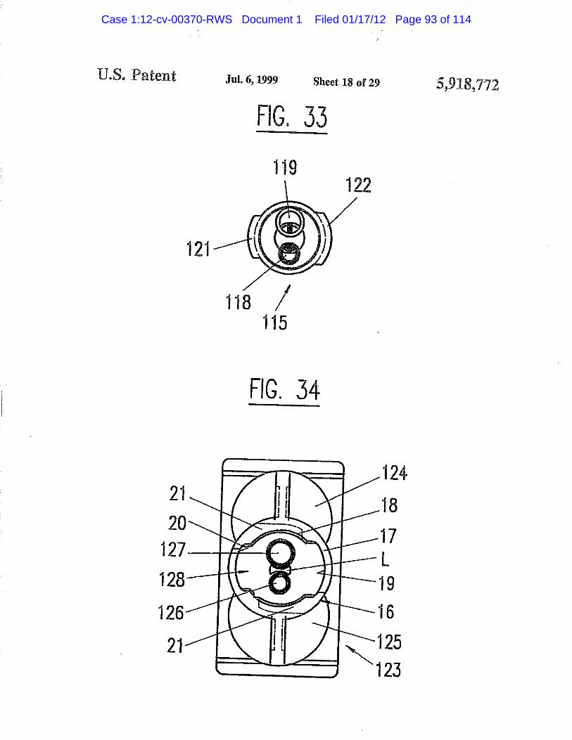
U.S. Patent jui. 6, xm sheet is of 29 3
FIG. 55
FIG. 34
Case 1:12-cv-00370-RWS Document 1 Filed 01/17/12 Page 93 of 114

U.S. Patent Jul. 6,1999 Sheet 19 of 29 5,918,772
FIG. 35
141 133 0 0 1 3 4 1 4 2
Case 1:12-cv-00370-RWS Document 1 Filed 01/17/12 Page 94 of 114

U.S. Patent Jul. 6,1999 Sheet 20 of 29
FIG. 36 5,918,772
FIG. 37
136A 133 152
137A
Case 1:12-cv-00370-RWS Document 1 Filed 01/17/12 Page 95 of 114

U.S. Patent Jul. 6,1999 Sheet 21 of 29 5,918,772
FIG. 38
• / / /
1 6 5 1 5 7
1 6 3
1 5 8 1 6 6
1 6 4 us-
EJ.
Case 1:12-cv-00370-RWS Document 1 Filed 01/17/12 Page 96 of 114

Jul. 6,1999 Sheet 22 of 29 5,918,772
FIG. 39
170Â 1 7 0
FIG. 40
1 5 7 1 9 4
167A 1 9 5 158 1 9 2
Case 1:12-cv-00370-RWS Document 1 Filed 01/17/12 Page 97 of 114

XJ.S, Patent Jul. 6,1999 Sheet 23 of 29 5,918,772
FIG. 41
157B 158B
FIG. 42
196
1 6 0 A — ®
is | | D
FIG. 43
194A
160A
195A 192A
Case 1:12-cv-00370-RWS Document 1 Filed 01/17/12 Page 98 of 114

ILS. Patent
FIG. 44 Jul. 6,1999 Sheet 24 of 29 5,918,772
162Â
Case 1:12-cv-00370-RWS Document 1 Filed 01/17/12 Page 99 of 114

U.S. Patent Jul. 6,1999 Sheet 25 of 29 5,918,772
FIG, 45
Case 1:12-cv-00370-RWS Document 1 Filed 01/17/12 Page 100 of 114

U.S. Patent Jul. 6,1999 Sheet 26 of 29 5 , 9 1 8 , 7 7 2
FIG. 46
191A 191
FIG. 47
179A 181 1 5 2 /
1 8 2 180A
Case 1:12-cv-00370-RWS Document 1 Filed 01/17/12 Page 101 of 114

U.S. Patent Jul. 6,1999 Sheet 27 of 29 5,918,772
FIG. 48
170A 170
i - m
— 1 6 5 •1
— 2 1 3 215
— 1 7 2 154
y en 216
x 2 1 1 1
FIG. 49
FIG. 50
167A 158 192 195
7 1 . 215 216 158
Case 1:12-cv-00370-RWS Document 1 Filed 01/17/12 Page 102 of 114

U.S. Patent Jul. 6,1999 Sheet 28 o f 29 5 , 9 1 8 , 7 7 2
FIG. 51 FIG. 52
217
FIG. 53
2 1 9
FIG. 54
FIG. 55 FIG. 56
Case 1:12-cv-00370-RWS Document 1 Filed 01/17/12 Page 103 of 114

XLS. Patent jui. 1999 sheet 29 of 29 5,918,772
FIG. 57 FIG. 58
Case 1:12-cv-00370-RWS Document 1 Filed 01/17/12 Page 104 of 114

5,918,772 1 2
BAYONET FASTENING DEVICE FOR THE Finally, all bayonet attachment means of the prior art ATTACHMENT OF AN ACCESSORY TO A have, in common, that the bayonet prongs of the cartridge
MULTIPLE C O I W O N ^ T C ^ T R I D G E OR are relatively small and therefore of limited structural rigid-DISPENSING DEVICE ity and strength. This allows the possibility of distortion and
CROSS-REFERENCE 5 ^ of greater significance due to the trend towards smaller The present application is a continuation in part of patent ® k e r ^ f ^ 1 5 therefore high backpressures, the result
application Ser. No. 08/403,172 filed Mar. 13, 1995, now *f i n g '®?kage ,al ™ raiX6r l o carlndge sealing interface abandoned, and of the continuation in part of patent appli- durinS dispensing. ajfco Ser. No. 08/522.109, filed Aug. 31.1995 aov, aba„- ^ SUMMARY OF THE INVENTION
BACKGROUND OF THE INVENTION 0 n ^^ P" o r arU ¡1 is an object of the present . , . . . invention to provide for a bayonet attachment device for
The present uivention relates to a bayonet fastening attachi a m i x e r , o r c l o s u r e J e a n s o r o t h e r a c c device for the attachment of an accessory 0 a dispensing s u c h as a n ad ter o r a c o n n e c t i n ^ t o a m u l i i £ device, in particular for the attachment of a mixer to a is „ , a^JL^ J,, • • T 1 ( F , two-component cartridge. component dispensmg device m particular a two component
There exists a great number of mixers and cartridges having means for attaching the mixer lo the cartridge, 4 , f stres® c a u s e^ Sreat65. f o r c , f to
according to U.S. Pat. No. 4,767,026 or U.S. Pat. No. ^ . t r e n d ^ards smaller mixer diameters as well as pro-4,538,920 where the mixer has two bayonet locking lugs 20 V l d u l g p roved mterface seahng. inserted into corresponding prongs on the cartridge by This object is attained with a device wherein said bayonet rotation. On one hand, the rotary locking movement of the attachment means at the dispensing apparatus or cartridge is complete mixer will cause contamination of one chemical formed as ring-shaped bayonet socket, with at least two component against the other chemical component at the internal recesses or an inner circular groove with at least two interface between the cartridge and the mixer, in that these ^ bayonet cutout followed by adjacent bayonet retaining components will be transported from one outlet to the other means, and wherein the bayonet attachment means of the outlet, from one inlet to the other inlet, causing ail uudesired accessory comprises at least two bayonet lugs corresponding reaction between these chemical components at the interface t o 0111 outs-between cartridge and mixer or closure means, and eventu- It is another object of the invention that alignment of the ally carrying such a reaction back into the cartridge outlets, 30 accessory inlets to the cartridge outlets takes place in one thus causing plugging of the outlets. On the other hand there position only to avoid cross contamination. This object is exist situations where it is necessary to connect and attach attained with a device wherein said bayonet attachment the mixer or accessory to a multiple component cartridge or means at the dispensing apparatus or cartridge and at the dispensing device in a predetermined position, such as when accessory have means for coded alignment of the accessory cartridge outlets or mixer inlets are of a different size for 35 to the dispensing apparatus or cartridge, different relative mixing ratios or when mixers or accesso- other objects and improvements of the device are defined ries are refitted for reuse. in the dependent claims.
There exists a need to connect and attach a mixer or accessory to a multiple component cartridge or dispensing BRIEF DESCRIPTION OF THE DRAWINGS device in a predetermined orieniation, such as when car- 40 The invention will he explained in more detail hereinafter tridge oudecs or mixer inlets are of a different size for with reference to a drawing of embodiments, different relative mixing ratios or when special high ratio FIGS. 1-6 show a first embodiment of the invention with a mixers are used for greater mixing efficency and when rotatable mixer housing, wherein mixers or accessories are refitted for reuse. In the latter case FIG. 1 is a longitudinal section of a mixer, of reuse, it is necessary to avoid any possibility of cross 45 FIG. 2 is a view of the inlet end of the mixer, contamination of one chemical component against another FIG. 3 is a longitudinal section of a cartridge, during refitting. Such cross contamination of reactive chemi- FIG. 4 is a top view of the cartridge of FIG. 3 with cal systems can cause plugging at the cartridge outlets and distanced outlets and ring-shaped bayonet means, cause a reaction back into and within the cartridge. FIG. 5 is a longitudinal section of a cartridge having two
U.S. Pat. No. 5,228,599 discloses a multiple dispensing so containers with different cross-sectional areas, cartridge having a mixer attached thereto with the aid of a FIG. 6 is a top view of the cartridge of FIG. 5 with coupling nut having an internal thread, wherein each storage distanced outlets and ring-shaped bayonet means, cylinder ends in a dispensing opening which forms a side by FIGS. 7-13 show a second embodiment of the invention side outlet, whereas the inlet of the mixer is not defined. The comprising a coupling ring, wherein mixer is put on the cartridge and secured by a coupling nut 55 FIG. 7 is a longitudinal section of a mixer, via an external thread at the cartridge. FIG. 8 is a view of the inlet end of the mixer,
Another cross contamination situation can occur when a FIG. 9 is a longitudinal section of a cartridge with clean mixer or accessory inlet area or closure plugs are able distanced outlets and ring-shaped bayonet means, to make any form of incorrect alignment contact, such as by FIG. 10 is a top view of the cartridge of FIG. 9 with a nose angular tipping, with the chemical components at the car- 60 piece, tridge outlet area during the process of initial placing of the FIG. 11 is a top view of a coupling ring, mixer or closure plugs against the cartridge in preparation FIG. 12 is a section of the coupling ring of FIG. 11, for attachment. In that case, when fitting the same mixer or FIG. 13 is a longitudinal section of a variant of the mixer closure plugs in the correct position, it is possible to now of FIG. 7 and 8 attached to the cartridge of FIGS. 5 and 6 chemically contaminate the outlets of the cartridge. Again, 65 having containers with different cross-sectional areas, this can cause plugging and a reaction back into and within FIGS. 14-19 show a third embodiment of the invention with the cartridge. a locking ring permanently attached to the cartridge, wherein
Case 1:12-cv-00370-RWS Document 1 Filed 01/17/12 Page 105 of 114

5,918,772 FIG. 14 is a longitudinal section of a cartridge with
distanced outlets, FIG. 15 is a top view of the cartridge of FIG. 14, FIG. 16A is a view on the mixer side of a locking ring to
be attached to the cartridge, FIG. 16B is a view on the cartridge side of the locking
ring or FIG. 16A. FIG. 17 is a section of the locking ring according to the
line XVII—XVn of FIG. 16B, FIGS. 18 and 19 show in two longitudinal sections at 90°
to each other a mixer attached to the cartridge of FIG. 14 with the locking ring of FIGS. 16A-17, in the locked position. FIGS. 20-25 show three embodiments of a closure cap for the cartridge, wherein
FIGS. 20-21 show as first embodiment a two part closure cap in a longitudinal section and a view on its canridge side face,
FIGS. 22-23 show as second embodiment a one part closure cap for use with a coupling ring in a longitudinal section and a view on its cartridge side face. FIGS. 24-25 show as third embodiment a one part closure cap for use with a locking ring attached to the cartridge in a longitudinal section and a view on its cartridge side face.
FIG. 46 is a top view of the cartridge of FIG, 41, and FIG. 47 is a view of the inlet end of the mixer.
FIGS. 48-58 show several further coding means at both the cartridge and the mixer for preventing cross-contamination
5 by erroneous attachment of the mixer onto the cartridge, wherein
FIG. 48 is a top view of a cartridge like in FIG- 39. with additional coding means,
FIG. 49 is a section of the inlet end of a mixer like in FIG. io 38, with additional coding means,
FIG. 50 is a view of the inlet end of the mixer of FIG. 49. FIGS. 51 and 52 show a variant of the coding means at the cartridge and mixer. FIGS. 53 and 54 show a further variant of the coding means
15 at the cartridge and mixer. FIGS. 55 and 56 show a further variant of the coding means at the cartridge and mixer. FIGS. 57 and 58 show a further variant of the coding means at the cartridge and mixer.
20 DETAILED DESCRIPTION OF THE
INVENTION FIGS. 1-2 show a mixer 1 comprising a mixer housing 2,
a mixer element group 3, the mixer outlet 4 and a mixer inlet FIGS. 26-28 show an alternative embodiment of the inven- 25 ^ ^ s ^ twQ s e p a ;a t e d M e l p a r t s 6 aild 7f w h i c h ^
30
35
40
tion with a ring-shaped bayonet socket at the rotatable mixer housing, wherein
FIG. 26 is a longitudinal section of a mixer attached to a partially shown cartridge,
FIG. 27 is a view of the inlet end of the mixer, and FIG. 28 is a top view of the cartridge of FIG. 26.
FIGS. 29-31 show a further embodiment of the invention with a ring-shaped bayonet socket at the cartridge, wherein
FIG. 29 is a longitudinal seciion of a mixer attached to a partially shown canridge,
FIG. 30 is a view of the inlet end of the mixer, and FIG. 31 is a top view of the cartridge of FIG. 29.
FIGS. 32-34 show a further embodiment of the invention with a ring-shaped bayonet socket at the cartridge, wherein
FIG. 32 is a longitudinal seciion of a mixer attached to a partially shown cartridge,
FIG. 33 is a view of the inlet end of the mixer, and FIG. 34 is a top view of the cartridge of FIG. 32,
FIGS. 35-37 show an further embodiment of the invention with a sector-shaped bayonet socket at the cartridge, wherein 45
FIG. 35 is a longitudinal seciion of a mixer attached to a partially shown cartridge,
FIG. 36 is a top view of the cartridge of FIG. 35, and FIG. 37 is a view of the inlet end of the mixer.
FIGS. 38-40 show an alternative embodiment of the inven-tion with a sector-shaped bayonet socket at the cartridge, wherein
FIG. 38 is a longitudinal section of a mixer attached to a partially shown cartridge,
HG. 39 is a top view of the cartridge of FIG. 38, and FIG. 40 is a view of the inlet end of the mixer.
FIGS. 41-44 show a further embodiment of the invention with a coupling ring, wherein
FIG. 41 is a longitudinal section of a mixer, FIG. 42 is a longitudinal section of a coupling ring, FIG. 43 is a top view of the coupling ring of FIG. 42, and FIG. 44 is a longitudinal section of the mixer attached to
a partially shown cartridge via the coupling ring. FIGS. 45-47 show a further embodiment of the invention with a sector-shaped bayonet socket at the mixer, wherein
HG. 45 is a longitudinal section of a mixer attached to a partially shown canridge,
50
55
60
65
integral with a properly aligned separating element 3S of the mixer element group 3. This mixer is attached to the cartridge by matching the mixer different width bayonet lugs 10, 11 to the different width bayonet sockets 19, 20 while pressing the mixer onto the cartridge and by rotating the mixer housing 2. Hie separated inlet parts 6 and 7 and the mixer element group 3 with the separating element 3S do not rotate. Separating element 3S serving in this embodiment as a separating means for guiding each chemical component separatedly to the first dividing element 3D of the mixer element group 3.
The mixer housing is provided with longitudinal ribs 8 that end at the larger diameter 9 of the mixer housing 2. The two lateral ends of the ribs are formed as bayonet lugs 10 and 11 cooperating with the bayonet retaining means of the cartridge. As follows from FIG. 2, the two lugs do not have the same width, lug 10 being larger than lug 11. As will be shown later, the different width of the lugs enable a coded alignment and attachment of the mixer to the cartridge.
The mixer element group 3 is connected to the separated inlet parts 6 and 7 and is disposed in such a way within the housing that the housing itself is rotatable around the mixer element group 3 with attached inlet parts 6 and 7, which are arranged at the inlet side of the first mixer element 3S serving in this embodiment as a separating means for guiding each component separately to the first dividing element 3D of the mixer element group 3.
In FIG. 3, the cartridge 12 comprises two cylindrical containers or chamber 13 of equal cross-sectional areas for a 1:1 metering ratio ending in two individual, separate cylindrical and distal outlets 14 and 15. The outside shapes of the distal outlets 14 and 15 of the cartridge correspond to the respective inside shapes of the separate inlets 6 and 7 of the mixer, (see FIG. 1). whereby the inlets of the mixer fit over the outlets of the cartridge for tightly sealed connec-tions. A reverse arrangement, where the inlet parts 6 and 7 fit into the outlet openings 14 and 15 is also possible.
In FIG. 4, the bayonet means 16 at the cartridge comprises a ring-shaped bayonet socket 17 with two internal recesses 18 and a circular opening with two diametrically opposed different width bayonet cutouts 19 and 20 for receiving the
Case 1:12-cv-00370-RWS Document 1 Filed 01/17/12 Page 106 of 114

5,9 19
corresponding different width bayonet lugs 10 and 11, (see FIG. 1), of the mixer, allowing coded introduction of the mixer in oae predetermined position only. The flange parts 21 adjacent to the cutouts serve as bayonet retaining means for securing the lugs of the mixer.
The ring-shaped bayonet means provides, in particular, for increased strength of the bayonet retaining means and increased structural rigidity of the outlet end of the cartridge when, during dispensing, the hydraulic forces transmitted from the attached mixer are at a maximum. This arrange-ment is a substantial improvement in comparison with the prior art bayoner prongs.
FIGS. 5 and 6 show a variant to the embodiment shown in FIGS. 1-4 in that the containers 22 and 23 of cartridge 24 have different cross-sectional areas for metering ratios other than 1:1.
In both described cases, in order to attach the mixer to the cartridge, the mixer can only be aligned with its bayonet lug widths corresponding to the different width cut outs of the bayonet sockets, then pressed onto the cartridge such that when the mixer is in place and the outlets and inlets are connected, the mixer housing 2 is rotated by 90° for the engagement of the bayonet lugs 10, 11 in the bayonet retaining means 21 of the cartridge. This attachment method prevents contamination of one component by the other at the mixer-cartridge interface yet enabling a quick coded attach-ment of the mixer.
FIGS. 7 and 8 show in a second embodiment a mixer 25 comprising a mixer housing 26, a mixer element group 3, a mixer outlet 4, and a mixer inlet section 27. This mixer is fixed to the cartridge (see FIG. 9) with the aid of a separate coupling ring (see FIGS. U and 12). The coupling ring 31 is provided with two bayonet lugs 32 and 33 corresponding to the bayonet cutouts 19, 20. respectively of the bayonet _ attachment means 16 at the cartridge. For better manual 3
gripping, ribs 34 are provided on the outer cylindrical surface.
[t follows in particular from FIG. 7 that the inixer inlet section 27 comprises two cylindrical, individual inlet open- ^ ings 28, 29 at the inlet side face of the first mixer element 3S serving in this embodiment as a separating means for guiding each component separately to the 'first dividing element 3D of the mixer element group 3. A slot 30 provides for a coded alignment of the mixer in regard to a cartridge.
Cartridge 35 (see FIGS. 9 and 10) is the same as cartridge 1 of FIG. 1 with the exception that the bottom of the bayonet attachment means 16 comprises a nose piece 36 correspond-ing to the slot 30 at the mixer (see FIGS, 7 and 8) for coded alignment of the mixer.
When connecting the mixer to the cartridge, the nose piece 36 on the cartridge fits into slot 30 of the mixer inlet section 27. This coded connection method assures not only one alignment possibility but also axial mixer attachment without rotation of the mixer housing, thus preventing contamination of one component by the other at the cartridge/mixer interface.
There are other coding means possible at the dispensing apparatus or cartridge and at the accessory for the codcd alignment of the accessory to the dispensing apparatus or cartridge, e.g. pins or protruding parts of all kind fitting into a recess or cavity or slot.
FIG. 13 shows a mixer 38 attached to a cartridge 75 having containers 76 and 77 with different cross-sectional areas, as a variant to the embodiment shown in FIGS. 5-12 in that the mixer inlet section 37 of mixer 38 has a separating means within the mixer, which separating means comprises
107,772 20
separated inlet chambers 39, 40, respectively having differ-ent cross-sectional areas, and lodged within a smaller com-bined diameter than the cartridge outlet with corresponding openings for each chamber for material to pass through.
The aforementioned separating means serves to maintain separation of the material flows up to the first dividing element 3D of the mixer element group 3. This separating means can have chambers with equal cross-sectional areas or have a cross-sectional area ratio other than 1:1. For
10 example, the ratio of the cross-sectional areas of the sepa-rating chambers can be adapted to the cross-sectional areas of the containers 76 and 77 of cartridge 75, respectively to its metering ratio. The separating means is fixedly connected to the inixer element group 3.
15 The cartridge 75 has the same attaching means as in FIGS. 5 and 6, and the mixer 38 is attached to the cartridge by means of the coupling ring 31.
The third embodiment of the invention according to the FIGS. 14-19 comprises a locking ring 51 that is snapped onto and permanently attached to the cartridge 42. The cartridge 42 comprises two cylindrical containers or cham-bers 43 of equal cross-sectional area, two distal outlets 45 and 46, and an attaching means 47 for attaching the locking
^ ring 51 and for limiting its rotational movement. The form of the atiaching means 47 is a circular edge 49 with two lugs 44 of same width and arranged around the two distal outlets with a circular undercut 48 at its base.
The locking ring 51 (see FIGS. 16A and 16B) and 17, snaps over circular edge 49 of the attaching means of the cartridge and remains attached to it. The locking ring 51 has an inner circular groove 52 forming a cartridge side edge 53 and a mixer side edge 54. The cartridge side edge 53 has two opposed cutouts 55, the width of which corresponds to the lugs 44 of the attaching, means whereby the inner diameter of the cartridge side edge 53 is slightly smaller than the outer diameter of the circular edge 49 of the attaching means of the cartridge. For snapping the locking ring to the cartridge, the ring is positioned so that the cutouts of its cartridge side edge are placed above the lugs of the attaching means and the ring is then pushed onto the cartridge so that the remaining cartridge side edge of the locking ring slides into the circular undercut 48 of the attaching means. The locking ring is also provided with a serration 58 for better manual
45 gripping. The mixer side edge 54 has two opposite cutouts 56 and
57 of different width corresponding to the lugs 10 and 11 of the mixer for insertion in one position only. These rwo cutouts are arranged at 90° to the cutouts 55 of the cartridge
50 side edgp. Thus, when the mixer 59 is to be attached to the locking ring on the cartridge and the locking ring is rotated by 90°, the remaining inside flange parts of both the car-tridge side edge and the mixer side edge serve as bayonet retaining means to encompass the mixer lugs 10 and 11 as
55 well as the lugs 44 of the attaching means 47 of the cartridge for strong securement.
FIGS. 18 and 19 show cartridge 42 of FIG. 14 with a mixer 59, which is similar to mixer 1 of FIG. 1 with the same mixer inlet section 5 with separate female inlets 6 and 7,
60 except that the housing 60 is not rotatable around the integral internal parts of the mixer and has no ribs 8, and the two bayonet lugs 10 and 11 are of different widths. FIG. 18 shows the mixer introduced within the locking ring 51 with the locking ring in its locked position and FIG. 19 shows a
65 section along the line XIX—XIX in FIG. 18 of the same assembly at 90°. It is evident that a mixer with separated inlet chambers can be attached likewise and also that a
Case 1:12-cv-00370-RWS Document 1 Filed 01/17/12 Page 107 of 114

5,918 ,772 8 12
cartridge may be one having containers with different cross- internal mixer parts comprising separate female inlets 83 sectional areas as in FIG. 5. and 84, the separating element 3S and the mixer elemenl
The above described system of the coded attachment, of group 3. The mixer element group or part thereof could also the mixer also allows for the coded attachment of closure he prealigned and be fixedly assembled within the mixer caps, adapters etc., thus preventing cross contamination and 5 housing. allowing closure cap re-use. The mixer housing 81 is provided with longitudinal ribs
The first embodiment of a coded closure cap 61, FIGS. 20 8, which end at the larger diameter 85. The larger end of the and 21, consists of two parts. The insert 62 has two male mixer housing has a nose piece 89, which provides a highly plugs 63 for closing the outlets of a cartridge, for example visible coded guide for alignment and insertion into the the distanced outlets 14 and 15 of cartridge 12 of FIG. 3. 10 slotted prong 90 of the cartridge. The mixer housing 81 is
In this embodiment it is shown bow the sealing effect of provided with a ring shaped bayonet socket attachment a plug at the cartridge outlet can be improved by providing tneans 100 comprising two bayonet flange parts 94 and 95 the male plug 63 with a second rim 63A reaching over the acting as bayonet retaining means, having two cut ouls 96 female cartridge outlet. The provision of such a male plug __ 97 in between. with a circumferential rim is of course not limited to this 1:1 The cartridge 86 has two cylindrical containers 87 and 88 example. with the distanced outlets 14 and 15 for fitting and sealing
The rotatable attaching means has two bayonet lugs 64 within the mixer inlet section 82. The cartridge front 86Ais and 65 of different widths corresponding to the lugs 10 and provided with a slotted prong 90 and a guide piece 91 for 11 of mixer 1 of FIG. 1. The outer surface of the cap is preventing incorrect insertion of the mixer and further with provided with ribs 66 and a collar 70 for better gripping. The 20 ^ 0 bayonet flanges 92 and 93 with tapered wedge shaped coded attachment of the closure cap to cartridge 12 or 24 is edges, corresponding in width with the mixer cutouts 96 and analogous to the attachment of mixer 1. 97, and with reduced diameter cutouts 98 and 99 in between.
The second embodiment, FIGS. 22 and 23, consists of a For attaching the mixer to the cartridge, the mixer inlet codcd closurc cap 67, which also has two plugs 68 for ^ part 82 is introduced into the cartridge by aligning the nose closing the outlets of a cartridge, for example the distanced piece 89 of the mixer housing within the slotted prong 90 male outlets 14 and 15 of cartridge 35 of FIG. 9, and a slot while the part 91 acts as a guide piece as the mixer inlets are 69 similar to slot 30 at mixer 25 for coded cooperation with pushed onto and over the cartridge distanced male outlets 14 nose piece 36 of cartridge 35. The outer surface of the cap and 15 such that the cartridge flanges 92 and 93 correspond is also provided with a collar 70 for better manual gripping. lfl to and enter within the mixer cutouts 96 and 97. Upon The attachment of the cap to cartridge 35 is achieved with ' rotating the mixer housing, the mixer bayonet flange parts 94 coupling ring 31 of FIG. 11, analogous to the attachment of arid 95 progressively move against the cartridge flanges 92 mixer 25 to that cartridge. and 93. because of their tapered wedge shaped depth,
The third embodiment of a coded closure cap 71, FIGS. forcing the mixer 80 against the cartridge front 86A. During 24 and 25, is similar to the second embodiment and com- 35 tbis m i x e r t0 cartridge attachment, the mixer housing 81 prises two plugs 72 for closing the distanced male outlets 45 " rotates 90° about the stationary integral internal mixer parts, and 46 of cartridge 42 of FIG. 14. FIG. 25 shows the The above bayonet arrangement, wherein the ring-shaped cartridge side of the closurc cap with two bayonet lugs 73, bayonet socket is at the accessory, as shown for a rotating 74 of different width and diametrically opposed on the edge mixer housing, can also be used in analogous manner for facing the cartridge. This closure cap is attached by means An previously shown embodiments and for the closure caps, of the locking ring 51 of FIGS. 18 and 19 and is also with the exception of the locking ring solutions. Alternative provided with a collar 70 for better manual gripping. coding means arranged around the outer periphery of the
The ring-shaped bayonet attachment means of the car- mixer housing are possible or is achieved by different widths tridge ensures a better stability of its outlet area and stronger o f cutouts and matching flange parte, retaining of the bayonet lugs compared with prior art bayo- 45 FIGS. 29-31 show a further embodiment wherein the net attachment means. mixer is provided with male inlet parts fitting into and
In the case of utilizing the advantages of the ring-shaped sealing within the female cartridge outlets, bayonet socket alone and without the need for coded FIG. 29 shows a mixer 101 comprising a mixer housing attachment, the bayonet lugs 10 and U. 32 and 33, 64 and 102 with mixer outlet 4 and and a mixer inlet section 103 65 at the mixer or closure cap or accessory as well as the so containing two separate male inlets 104 and 105 followed by corresponding bayonet cutouts 19 and 20 at the retaining a separating element 3S which in turn is fixedly attached to means at the cartridge or 56 and 57 at the locking ring 51, a properly aligned first dividing element 3D of the mixer may have the same widths. This applies also in the case element group 3. Also this mixer is attached to the cartridge when more than two lugs and corresponding cutouts are by matching the coding means of the mixer to the coding used, for example three or four respectively. 55 means of the cartridge, by pressing the mixer onto the
The FIGS. 26-28 show a further embodiment of the cartridge and by rotating the mixer housing 102 about the invention with an inverse bayonet arrangement as compared integral internal mixer parts comprising separate male inlets with those of the bayonet arrangement of the mixer and 104 and 105, the separating element 3S and the mixer cartridge according to FIGS. 1-4. FIG. 26 shows a mixer 80 element group 3. The mixer element group or part thereof comprising a mixer housing 81 with mixer outlet 4 and and so could also be prealigned and be fixedly assembled within the a mixer inlet section 82 containing two separated inlet parts mixer housing. 83 and 84 followed by a separating element 3S, which in The mixer housing 102 is provided with longitudinal ribs turn is fixedly attached to a properly aligned element 3D of 8 which end at the larger diameter 106, the two lateral ends the mixer element group 3. Also this mixer is attached to the of, which are formed as bayonet lugs 107 and 108, FIG. 30, cartridge by matching the coding means of mixer and 65 cooperating with the bayonet retaining means of the car-cartridge by pressing the mixer onto the cartridge and by tridge. Tfae bayonet lugs do not have the same width, lug 107 rotating the mixer housing 81 of the mixer about the integral being larger.
Case 1:12-cv-00370-RWS Document 1 Filed 01/17/12 Page 108 of 114

5,9 9
The cartridge 109, FIG. 31, has two cylindrical containers U0 and 111 with the distanced female outlets 112 and 113 for fitting and sealing over the male mixer inlets 104 and 105. The cartridge front 114 is provided with the same bayonet means 16 as the cartridge of FIG. 4. comprising a 5 ring shaped bayonet socket.
FIGS. 32-34 show a further embodiment wherein the mixer is provided with a male and a Female inlet part filling and sealing into/over the female/male cartridge outlets.
FIG. 32 shows a mixer 115 comprising a mixer housing 10
116 with outlet 4 and a mixer inlet section 117 containing a separate male inlet 118 and a separate female inlet 119 followed by separated chambers U7A and 117B, which in turn are fixedly attached to a properly aligned first dividing element 3D of the mixer element group 3. Also this mixer is 15
attached to the cartridge by pressing the mixer onto the cartridge and by rotating the mixer housing 116 about the integral internal mixer parts comprising separate male inlets 118 and 119, the separated chambers il7Aand 117B and the mixer element group 3. The mixer element group or part 20
thereof could also be prealigned and be fixedly assembled within the mixer housing.
The mixer housing 116 is provided with longitudinal ribs 8, which end at the larger diameter 120, the two lateral ends of which are formed as bayonet lugs 121 and 122, FIG. 33. 25
cooperating with the bayonet retaining means of the car-tridge. The bayonet lugs do not have the same width, bayonet lug 121 being larger.
The cartridge 123 has two cylindrical containers 124 and JQ 125 with one distanced male outlet 126 and one distanced female outlet 127 for, respectively, fitting and sealing within the separate female inlet 119 and over the separate male inlet 118 of the mixer. The cartridge front 128, FIG. 34. is provided with the same bayonet means 16 as the cartridge of 35 FIG. 4. comprising a ring shaped bayonet socket.
The embodiments of FIGS. 35-43 show sector-shaped bayonet sockets instead of complete ring-shaped ones. The function and the attaching of the accessory are the same as in the previous embodiments, so that the three different 40 embodiments of the bayonet means are illustrated in one respective example of mixer and cartridge, it is obvious that the sector-shaped bayonet socket and similar means can be provided on all other embodiments also.
FIG. 35 shows a mixer-cartridge assembly with a mixer 45 130 comprising a mixer housing 131 with outlet 4 and a mixer inlet section 132 containing two separate male inlets 133 and 134 followed by separating chambers 133A and 134A which in turn are fixedly attached to a properly aligned first dividing element 3D of the mixer element group 3. Also 50 this mixer is attached to the cartridge by pressing the mixer onto the cartridge and by rotating the mixer housing 131 about the integral internal mixer parts comprising separate male inlets 133 and 134, the separated chambers 133 A and 134A and the mixer element group 3. The mixer element 55 group or part thereof could also be prealigned and be fixedly assembled within the mixer housing.
The mixer housing 131 is provided with longitudinal ribs 8 which end at the larger diameter 135, the two lateral ends of, which are formed as bayonet lugs 136 and 137, FIG. 37, 60 cooperating with the sector-shaped bayonet sockets 145, 146, serving as bayonet retaining means of the cartridge. The bayonet lugs have the same width and are provided each with a rib 136A and 137A at it's end which both strengthen each lug and acts as a stop as well as ensuring that the mixer 65 can be turned and attached in one direction only. The upper surface of the lugs may have inclined surface parts so as to
¡,772 10
enforce the locking ability by an axial load. Corresponding inclined surface parts may also be located on the corre-sponding surface of the cartridge sector shaped bayonet sockets.
The cartridge 138 has two cylindrical containers 139 and I'M) with two distanced female outlets 141 and 142 for receiving and sealing over the separate male inlets 133 and 134. The cartridge front 143, FIG. 36, is provided with bayonet means comprising sector-shaped bayonet sockets 145,146 which act as prongs and are closed on one side by a rib 145A and 146A which connects to the cartridge end wall so as to stiffen and increase the strength of the bayonet prong. The cutouts 149 and 150 between the sector shaped bayonet sockets allow for the introduction of the mixer bayonet lugs 136 and 137.
In this embodiment the bayonet lugs and the sector shaped bayonet sockets have approximately the same width. The coding is achieved by other coding means on the mixer and on the cartridge. The cartridge front 143 is provided with a T-shaped protrusion 151 arranged between the two outlets and the mixer inlet face is provided with a similar protrusion 152 arranged off centre between the mixer inlets, see FIGS. 36 and 37.
The two T-shaped coding means allow the attachment of the mixer in one orientation only since, when putting the mixer onto the cartridge such that when the two prolusions are laying one upon the other, they will prevent the intro-duction of the mixer inlets into the cartridge outlets and also any contact between the cartridge outlets and the mixer inlets or plugs of closure means thus preventing cross contamination and prohibiting mixer/accessory attachment. It is obvious that the coding protrusions can have any shape other than a T-form, and could be, e.g.. in the form of a keyway allowing only one defined position in which to introduce the mixer having a corresponding protrusion, or two differently shaped keyways and corresponding protru-sions.
The coded alignment can be facilitated by visual coding means, e.g., a marking 153 at the cartridge outlet end and a marking 154 at the bayonet lug 137 of the mixer on the same side as the coding protrusion.
In the embodiment of FIGS. 38-40, the coding is achieved by cutouts of different widths between the lugs. FIG. 38 shows a mixer-cartridge assembly with a mixer 155 with a mixer housing 156, outlet 4 and integral internal mixer parts comprising two separate inlets 157 and 158 ending into a disc-shaped flange and followed by separated chambers 157Aand 158A which in turn are fixedly attached to a properly aligned first dividing element 3D of the mixer element group 3. Also this mixer is attached to the cartridge by pressing the mixer onto the cartridge and by rotating the mixer housing 156 about the integral internal mixer parts. The mixer element group 3 or part thereof, may also be prealigned and fixedly assembled within the mixer housing.
The mixer housing 156 is provided with longitudinal ribs 8, which end at the larger diameter 159, the two lateral ends of which are formed as bayonet lugs 160 and 161, FIG. 40, cooperating with the sector shaped bayonet retaining means of the cartridge. In this FIG. 38 and also in FIGS. 13,32,35 and 45 it is shown that the inlet end of the mixer housing has not only one cylindrical enlargement but two, e.g., one 159 at the inlet, lodging and sealing against the separate inlets 157, 158, followed by the second part 159A having an intermediate diameter and lodging and sealing against the separating means 157A. 158A. The bayonet lugs have the same widths but the gaps or cutouts 194,195 between them
Case 1:12-cv-00370-RWS Document 1 Filed 01/17/12 Page 109 of 114

5,918 11
are different, corresponding to the different widths of the sector shaped bayonet sockets on the cartridge.
These bayonet lugs 160,161, can be provided each with a rib 167, FIG. 40, on the reverse side of the mixer inlet which both strengthen the lug and act as stop as well as s limiting rotation in one direction only so as to prevent the mixer from being attached at 180° to the correct alignment. The upper surface of the lugs may have inclined parts, not shown, so as to enforce the locking and sealing ability by an axial force. Corresponding inclined parts, not shown, may lQ also be located on the corresponding surface of the cartridge sector shaped bayonet sockets.
The cartridge 162 has two cylindrical containers 163 and 164 with two distanced female outlets 165 and 166 for receiving and sealing over the separate male inlets 157 and 158. The cartridge front 168, FIG. 39, is provided with 15
bayonet means, comprising two sector-shaped bayonet sock-ets.
In FIG. 39, the bayonet means at the cartridge comprises two diametrically opposed sector-shaped bayonet sockets 169 and 170 acting as bayonet prongs for the bayonet lugs 20
of the mixer, the two sockets having different widths, socket 169 having the greater width. The two cut outs 171 and 172 between the sockets allow for the introduction of the cor-responding mixer bayonet lugs 160 and 161 into the sector shaped bayonet sockets 169, 170. As shown in this Figure, 25 the passages of the bayonet sockexs 169 and 170 commence as straight passages but become curved from the mid point onwards so as to achieve a greater strength against bayonet lug axial forces.
The passages can be wholly curved, without straight parts, 30 and wholly or partly curved passages can also be provided on the ring-shaped bayonet attachment means.
In order to prevent any inadvertent contact whatsoever of . the mixer or accessory inlet or inlets with the cartridge outlet or outlets by any form of tilting or tipping of one against the 35 other during incorrect alignment the larger cut out 195 at the mixer is provided with a V-shape nose 192 corresponding to a V-shape incision 193 at the larger socket 169 such that the mixer is kept outside of the narrower bayonet socket 170 by the V-shape nose 192. ^
In this embodiment also the coded alignment can be facilitated by visual coding means, e.g., marking 153 at the cartridge and marking 154 at the the corresponding lug.
In case no univocal attachment of a mixer to the cartridge 162 is necessary the cut outs between the lugs of the mixer 45 must be large enough to fit over the larger retaining means of the cartridge, whereas the visual coding means rest the same as previously described.
FIGS. 41-44 show a similar arrangement to that of the FIGS. 38-40 except that the mixer 200 is separate from 50 coupling ring 196, the latter being rotated about the station-ary mixer during the final rotary locking attachment of the coupling ring bayonet lugs 160A, 161A, into the sector shaped bayonet sockets 169,170 of the cartridge 162.
FIG. 41 shows mixer 200 with the outlet 4 and comprising 55 a housing 201 containing the mixer element group 3 in alignment with inlet part 197, the latter only partially contained within the mixer housing and comprising separate male inlets 157B, 158B and separate chambers 157C, 158C. A ridge 198 lodges and seals the inlet part 197 within the 60 mixer housing. The coupling ring 196 is preassembled and prealigned with the mixer inlet part 197 via a groove 199, FIG. 41, in the coupling ring 196. FIG. 43 shows coupling ring 196 with the same coded bayonet lugs 160A, 161A, cut outs 194A, 195A, visual coding 154 and V-shape nose 65 coding 192A as used in the embodiment according to FIG. 40.
,772 12
FIG. 44 shows the mixer 200 and the cartridge 162 when assembled together. Prior to such assembly, the coupling ring 196 may be pre-assembled to the mixer under sufficient tension such that both components are held together in the correct relative alignment for initial visual coded and initial axial mechanical coded contact and attachment of the mixer inlets 157B, 158B to the cartridge outlets 165.166 on the cartridge prior to the final rotary locking attachment of the coupling ring as described above. In this embodiment therefore, there is no rotation of the mixer housing 201 about the mixer inlet part 197 and element group 3 during attach-ment.
In the embodiment according to FIGS. 45-47 the sector-shaped bayonet sockets are at the mixer and the bayonet lugs at the cartridge, in analogy to the embodiment according to FIGS. 26-28.
FIG. 44 shows a mixer-cartridge assembly with a mixer 173 comprising a mixer housing 174 with outlet 4 and a mixer inlet section 175 containing the integral internal parts comprising two separate male inlets 176 and 177 followed by separated chambers 176A and 177A which in turn are fixedly attached to a properly aligned first dividing elemen) 3D of the mixer element group 3. Also this mixer is attached to the cartridge by pressing the mixer onto the cartridge and by rotating the mixer housing 174 about the separate male inlets 176 and 177, the separated chambers 176Aand 177A and the mixer element group 3. The mixer element group or part thereof could also be pre-aligned and be fixedly assembled within the mixer housing.
The mixer housing 174 is provided with longitudinal ribs 8, which end at the larger diameter 178. the two lateral ends of which are formed as two diametrically opposed sector-shaped bayonet sockets 179 and 180 (see FIG. 43) acting as prongs which are both closed al one side by a rib 179A. and 180A connecting to the mixer wall so as to stiffen and increase the strength of the bayonet prong. The cut outs 181 and 182, between the sockets, allow for the introduction of the cartridge bayonet lugs cooperating with the bayonet retaining means of the mixer.
The cartridge 183 has two cylindrical containers 184 and 185 with two distanced female outlets 186 and 187 for fitting and sealing over the separate male inlets 176 and 177. The cartridge front 188, FIG. 42, is provided with bayonet means, comprising sector-shaped bayonet lugs 190 and 191 having the same width and each being provided with a rib 190A and 191A at it's end which strengthens the lug and act as a stop as well as limiting rotation in one direction only so as to prevent the mixer from being attached at 180® to the correct alignment. The upper surface of the lugs may have inclined surface parts, not shown, so as to enforce the locking ability by an axial load. Corresponding inclined surface parts, not shown, may also be located on the corre-sponding surface of the mixer sector shaped bayonet sock-ets.
The lugs and the cutouts have approximately the same width. Thus the required coding is achieved by other coding means on the mixer and on the cartridge. Therefore the cartridge front 188 is provided with the T-shaped protrusion 151 arranged between the two distanced female outlets and the mixer inlet face is provided with a similar shaped protrusion 152 arranged off center between the mixer inlets. See FIGS. 46 and 47.
The two T-shaped coding means allow the introduction of the mixer in one position only, since the placing of the mixer onto the cartridge is such that, when the two protusions are laying one upon the other, they will prevent the introduction
Case 1:12-cv-00370-RWS Document 1 Filed 01/17/12 Page 110 of 114
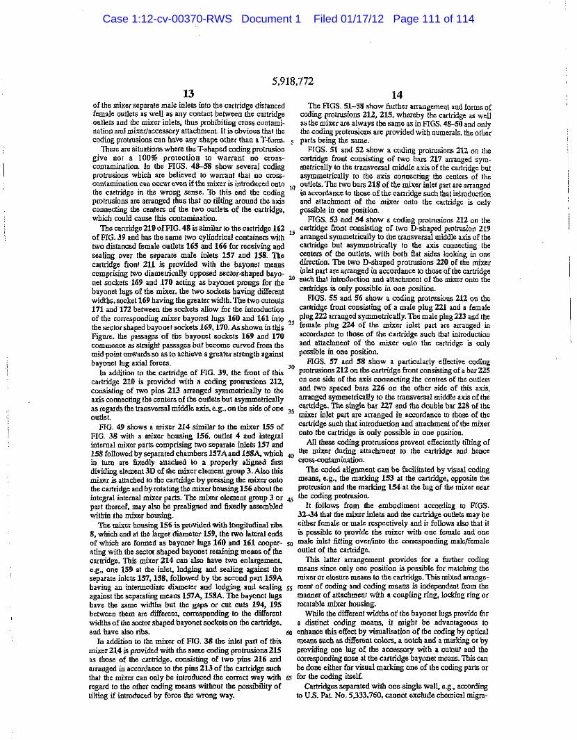
5,9 19
of the mixer separate male inlets into the cartridge distanced female outlets as well as any contact between the cartridge outlets and the mixer inlets, thus prohibiting cross contami-nation and mixer/accessory attachment. It is obvious that the coding protrusions can have any shape other than a T-form.
There are situations where the T-shaped coding protrusion give cot a 100% proiection to warrant no cross-contamination. In the FIGS. 48-58 show several coding protrusions which are believed to warrant that no cross-contamination can occur even if the mixer is introduced onto the cartridge in the wrong sense. To this end the coding protrusions are arranged thus that ao tilting around the axis connecting the centers of the two outlets of the cartridge, which could cause this contamination.
The cartridge 210 of FIG. 48 is similar to the cartridge 162 of FIG. 39 and has the same two cylindrical containers with two distanced female outlets 165 and 166 for receiving and sealing over the separate male inlets 157 and 158. The cartridge front 211 is provided with the bayonet means comprising two diametrically opposed sector-shaped bayo-net sockets 169 and 170 acting as bayonet prongs for the bayonet lugs of the mixer, the two sockets having different widths, socket 169 having the greater width. The two cutouts 171 and 172 between the sockets allow for the introduction of the corresponding mixer bayonet lugs 160 and 161 into the sector shaped bayonet sockets 169,170. As shown in this Figure, the passages of the bayonet sockets 169 and 170 commence as straight passages but become curved from the mid point onwards so as to achieve a greater strength against bayonet lug axial forces.
In addition to the cartridge of FIG. 39. the front of this cartridge 210 is provided with a coding protrusions 212, consisting of two pins 213 arranged symmetrically to the axis connecting the centers of the outlets but asymmetrically as regards the transversal middle axis, e.g.. on the side of one outlet.
FIG. 49 shows a mixer 214 similar to the mixer 155 of FIG. 38 with a mixer housing 156, outlet 4 and integral internal mixer parts comprising two separate inlets 157 and 158 followed by separated chambers 157A and 158A, which in turn are fixedly attached to a properly aligned first dividing element 3D of the mixer element group 3. Also this mixer is attached to the cartridge by pressing the mixer onto the cartridge and by rotating the mixer housing 156 about the integral internal mixer parts. The mixer element group 3 or part thereof, may also be prealigned and fixedly assembled within the mixer housing.
The mixer housing 156 is provided with longitudinal ribs 8, which end at the larger diameter 159, the two lateral ends of which are formed as bayonet lugs 160 and 161 cooper-ating with the sector shaped bayonet retaining means of the cartridge. This mixer 214 can also have two enlargement, e.g., one 159 at the inlet, lodging and sealing against the separate inlets 157,158, followed by the second part 159A having an intermediate diameter and lodging and sealing 55 against the separating means 157A, 158A. The bayonet lugs have the same widths but the gaps or cut outs 194, 195 between them are different, corresponding to the different widths of the sector shaped bayonet sockets on the cartridge, and have also ribs. 60
In addition to the mixer of FIG. 38 the inlet part of this mixer 214 is provided with the same coding protrusions 215 as those of the cartridge, consisting of two pins 216 and arranged in accordance to the pins 213 of the cartridge such that the mixer can only be introduced the correct way with regard to the other coding means without the possibility of tilting if introduced by force the wrong way.
14,772 20
The FIGS, 51-58 show further arrangement and forms of coding protrusions 212, 215, whereby the cartridge as well as the mixer are always the same as in FIGS. 48-50 and only the coding protrusions are provided with numerals, the other
5 parts being the same. FIGS. 51 and 52 show a coding protrusions 212 on the
cartridge front consisting of two bars 217 arranged sym-metrically to the transversal middle axis of the cartridge but asymmetrically to the axis connecting the centers of the
1(J outlets. The two bars 218 of the mixer inlet part are arranged in accordance to those of the cartridge such that introduction and attachment of the mixer onto the cartridge is only possible in one position.
FTGS. 53 and 54 show a coding protrusions 212 on the cartridge front consisting of two D-shaped protrusion 219 arranged symmetrically to the transversal middle axis of the cartridge but asymmetrically to the axis connecting the centers of the outlets, with both fiat sides looking in one direction. The two D-shaped protrusions 220 of the mixer inlet part are arranged in accordance to those of the cartridge
2]} such that introduction and attachment of the mixer onto the cartridge is only possible in one position.
FIGS. 55 and 56 show a coding protrusions 212 on the cartridge front consisting of a male plug 221 and a female plug 222 arranged symmetrically. The m ale plug 223 and the
25 female plug 224 of the mixer inlet part are arranged in accordance to those of the cartridge such that introduction and attachment of the mixer onto the cartridge is only possible in one position.
FIGS. 57 and 58 show a particularly effective coding 30 protrusions 212 on the cartridge front consisting of a bar 225
on one side of the axis connecting the centres of the outlets and two spaced bars 226 on the other side of this axis, arranged symmetrically to the transversal middle axis of the cartridge. The single bar 227 and the double bar 228 of the
35 mixer inlet part arc arranged in accordance to those of the cartridge such that introduction and attachment of the mixer onto the cartridge is only possible in one position.
All these coding protrusions prevent effeciently tilting of the mixer during attachment to the cartridge and hence cross-contamination.
The coded alignment can be facilitated by visual coding means, e.g., the marking 153 at the cartridge, opposite the protrusion and the marking 154 at the lug of the mixer near the coding protrusion.
It follows from the embodiment according to FIGS. 32-34 that the mixer inlets and the cartridge outlets may be either female or male respectively and ii follows also that it is possible to provide the mixer with one female and one male inlet fitting over/into the corresponding male/female outlet of the cartridge.
This latter arrangement provides for a further coding means since only one position is possible for matching the mixer or closure means to the cartridge. This mixed arrange-ment of coding and coding means is independent from the manner of attachment with a coupling ring, locking ring or rotatable mixer housing.
While the different widths of the bayonet lugs provide for a distinct coding means, it might be advantageous to enhance this effect by visualisation of the coding by optical means such as different colors, a notch and a marking or by providing one lug of the accessory with a cutout and the corresponding nose at the cartridge bayonet means. This can be done either for visual marking one of the coding parts or
65 for the coding itself. Cartridges separated with one single wall, e.g., according
to U.S. Pat. No. 5,333,760, cannot exclude chemical migra-
Case 1:12-cv-00370-RWS Document 1 Filed 01/17/12 Page 111 of 114

5,918 ,772 16 12 16
tioD through such a single wall separation barrier and therefore separation at the cartridge outlets is not sufficient to prevent migration and therefore a reaction within the cylinders during storage.
It follows in particular from the FIGS. 5.14, 26,29, 32, 35,38 and 41 that it is advantageous to provide for a single piece cartridge consisting of two complete, preferably cylin-drical containers which are substantially separated by an air gap L in between, see e.g. FIG. 32. This assures a total chemical separation along the whole length where the chemicals are contained, ahead of the cylinder pistons, all the way to the top of the outlets where, during storage, a closure means is installed. During dispensing, this separa-tion is further maintained within the mixer up to the first dividing element 3D of the mixer element group.
The invention however, is not limited to air gap separated containers and applies as well to cartridges with containers separated by one single wall according to FIG. 3.
It follows from the above description that the inventive cartridge to accessory attachment combination provides in particular for cartridge containers separated by an air gap up to and including the individual outlets and for a port to port coded alignment for same or dissimilar size ports, with no cross-contamination caused by rotation or random attachment, while maintaining separation past the interface and well into the mixer, so as to hinder the spreading of any possible reaction and plugging of the components at the interface and back into the cartridge outlets. This combina-tion also provides optimization of the mixing performance especially, but not uniquely, for ratios other than 1:1,
While the foregoing description and the drawing of the cartridge embodiments pertained to multiple component cartridges with side-by-side containers the teaching of the present invention is not limited thereto and can be applied as well to cartridges with concentric containers or otherwise arranged and formed containers.
However, the principle of coded attachment ensures both the correctly aligned connection of a mixer or accessory to cartridge outlets since only one position of the mixer or 40 accessory is possible and, in the case of the re-connection of mixer or closure cap to a cartridge, eliminates the possibility of cross-contamination.
Furthermore, and in respect to mixers, all the above
achieved such that each of the two material streams leaving the separating means, or the first element group attached to the separating means, will be evenly divided by the leading edge of the first element of the element group, or portion
5 thereof attached to the housing, for optimimum mixing efficiency.
It is evident that instead of cylindrical inlets and outlets, D-shaped or differently shaped similar or dissimilar sized inlets and outlets are possible. Furthermore, the same prin-
10 ciple can also be used for a dispensing device, or cartridge, for more than two components.
We claim: 1. A mixer Cor a cartridge, the cartridge having a plurality
of chambers each having an outlet, the mixer comprising: a housing; a mixer element disposed in said housing; a plurality of inlets Cor engagement with the outlets of the
cartridge and mounted on said housing; and a bayonet coupling on said housing for detachably con-
necting said mixer to the multichamber cartridge, said bayonet coupling having locked and unlocked posi-tions;
said inlets being fixedly disposed relative to said housing so that said housing is disposed in the same position relative to the cartridge when said bayonet coupling is in either said locked position or said unlocked position.
2. A mixer according to claim 1, wherein said bayonet coupling comprises a pair of diametrically opposed lugs.
3. A mixer according to claim 2, wherein said lugs are fixed relative to said housing.
4. A mixer according to claim 3. wherein one of said lugs is larger than the other lug.
5. A mixer according to claim 1, wherein said bayonet coupling comprises a coupling ring connected to one end of said housing around said inlets, said coupling ring being ro tat able relative to said bousing.
6. A mixer according to claim 5, wherein said coupling ring has a pair of diametrically opposed lugs.
7. A mixer according to claim 6, wherein one of said lugs is larger than the other lug.
8. A mixer according to claim 5, wherein said coupling ring has a pair of diametrically opposed cutouts.
9. A mixer according to claim 8, wherein one of said
15
20
25
30
35
described embodiments have the advantage of comprising 45 c u t m t & ^ { ^ & e Qther cut_0llt the minimum number of parts and of being compact result- m A m j x c r a c c o r d i n t o c l a i m w h e r c i n sa id ^ mg in low molding and assembly costs since the whole inlet h a s a c o d i c o m p r i s e d o f o n e o f a radially extending section comprising the separating means and the mixer protrusion or cutout element group is made in one piece. Also the integral U. A mixer for a cartridge, the cartridge having a plurality construction of this internal part ensures proper alignment 50 o f c h a m f a e i s e a c h h a v i n g ^ out Ie t j ^ m i x 6 r comprising: thus providing optimum mixing efficiency.
in the case of the first embodiment according to FIG. 1 when a relatively long mixer element group is used and where rotational friction between this mixer element group and the mixer housing might cause problems, it may be preferable to separate a part or the whole of the mixer element group from the separating means of the inlet section such that a pan or the whole of the mixer element group may be fixedly assembled within the housing and therefore it rotates with the housing while connecting the mixer to the cartridge.
In this case;—and as seen from the mixer inlet to the mixer outlet—the leading edge of the first element of the mixer element group, or of a portion thereof, must be fixedly assembled within the housing in a pre-aligned position. Therefore, after rotating the housing so as to attach the mixer to the cartridge, correct alignment of the elements is
55
60
65
a housing; a mixer element disposed in said housing; a plurality of inlets for engagement with the outlets of the
cartridge and mounted on said housing; a bayonet coupling on said housing for detachably con-
necting said mixer to the multichamber cartridge, said bayonet coupling having locked and unlocked posi-tions; and
a coding element that permits said inlets of said housing to be aligned and connected to the outlets of the cartridge in only one orientation.
12. A mixer according to claim 11, said inlets being fixedly disposed relative to said housing so that said housing is disposed in the same position relative to the cartridge when said bayonet coupling is in either said locked position or said unlocked position.
Case 1:12-cv-00370-RWS Document 1 Filed 01/17/12 Page 112 of 114

5,918 ,772 17 12
13. A mixer according to claim 11, wherein said bayonet a mixer element disposed in said housing; and coupling comprises a pair of differently sized diametrically a second bayonet coupling complementary with said opposed lugs, wherein said coding element comprises said first bayonet coupling of said cartridge, said first differently sized lugs. bayonet coupling being detachable from said second
14. A mixer according to claim 13, wherein said lugs are 5 bayonet coupling and together forming a detachable fixed relative to said housing. bayonet assembly, said first and second bayonet
15. A mixer according to claim 13. wherein said coding couplings having locked and unlocked positions; element further includes one of a cutout for protrusion said inlets being fixedly disposed relative to said housing formed on said bayonet coupling. so that said housing is disposed in the same position
16. A mixer according to claim 13, wherein said bayonet 10 relative to the cartridge when said bayonet coupling is coupling comprises a coupling ring connected to one end of in either said locked position or said unlocked position, said housing around said inlets, said coupling ring being 28. A dispensing device according to claim 27, wherein rotatable relative to said housing. said first bayonet coupling comprises a pair of diametrically
17. A mixer according to claim 13, wherein said diameiri- opposed sockets and said second bayonet coupling com-cally opposed lugs are formed on said coupling ring. u prises a pair of diametrically opposed lugs complementary
18. A mixer according to claim 11, wherein said bayonet to said sockets. connector comprises a coupling ring connected to one end of 29. A dispensing device according to claim 28, wherein said housing around said inlets, said coupling ring being said lugs are fixed relative to said housing, rotatable relative to said housing, said coupling ring having 30. A dispensing device according to claim 27. wherein a pair of differently sized diametrically opposed cutouts, 20 said first bayonet coupling comprises a locking ring rotat-wherein said coding element comprises said differently sized ably mounted to one end of said chambers around said cutouts. outlets, said locking ring having a pair of diametrically
19. A mixer according to claim 18, wherein said coding opposed cutouts, and said second bayonet coupling corn-element further comprises a radially extending protrusion prises a pair of diametrically opposed lugs fixed to said formed on said coupling ring. 15 housing and complementary to said cutouts, wherein said
20. A cartridge for a mixer, the mixer having a plurality of locking ring is rotatable between a lock position and an inlets, the cartridge comprising: unlock position, said cutouts receiving said lugs in said
a plurality of chambers each having an outlet for engage- unlock position and said locking ring being rotatable to said ment with the inlets of the mixer, lock position while said housing stays roiationally stationary
a bayonet coupling on the cartridge for detachably con- 30 reI^vei r ° s a i d cartr\dSe- , . . necting said cartridge to the mixer, said bayonet cou- ? } ' A ^ n s r n g device according to claim 30. wherein pling having locked and unlocked positions: and s a i d c ^ o u t s arf differently sized and said lugs are comple-
, , . .. . , A £ , mentarily sized so that said inlets of said mixer are aligned a coding element that permits said outlets of said cham- ^ c o im 'ec ted to t b e i v e 0U(Iets o f sa id cartrid|e k
bers to be aligned arid connected to the respective inlets 3Jf . Qne or ienta l ion> of the mixer in only one orientation. . . . .
21 A t "d e acco din t claim 20 where' said dispensing device according to claim 27. wherein . ca n ge g , in 1 said first bayonet coupling comprises a pair of diametrically
bayonet coupling comprises means for maintaining the o p p o s e d J o u t s i o J e d £ o n e end of said chambers around mixer in the same fixed position relative, to the cartridge J g 0(JtIets a n d s a k j s e c o n d b c H c o m p r i s e s 3 when said bayonet coupling is m either said locked position ^ ^ having a pair of diametrically opposed lugs or said unlocked position. , . ... . . . . , .r ^ a . • j .. t , . , . complementary with said cutouts, said coupling ring being
22. A cartridge according to claim 21, wherein said rot/abl m o l i t e d r c l a t i v e t0 s a i d h o u s i n ^ 4 e r 4 saiJ bayonet coupling composes a pair of differently sized dia- > ^ ^ ^ b e t w e e n a ^ J a n d m metrically opposed sockets positioned around said outlets ^ * i d ^ c u t o u t s r e c e i v i n J d sa id wherein said codmg clement comprises said differently sized # UDlock a n d s a i d c o u p U n g ^ f be i lJg ro^ tab le ta so<l_e ; . . _„ , . . , said lock position while said housing stays rotationally 23. A cartridge accordmg to claim 20, wherein said ^ ¿ l a t i v e to s a i d c a r t r i d g c . bayonet coupling comprises a lociang nng rotatably 33_ A d i s p e n s i n g d e v i c e according to claim 32, wherein mounted to one end of said chambers around said outlets, s a i d c u l o u { / a r e d i|e r e n t l y s i z e d „ d s a i d l l igs ^ c o m p l e -said lockmg nng having a pair of differently sized diametn- SQ m e n l a i U s i z e d ^ that J d ^ o f s a i d J ^ are ^ ^ cally opposed cutouls, wherem sand coding element com- a a d c o a n e c t e d tQ the re e c t i v e o u t l e t s o f sa id cartr idge ^ pnses said differently sized cutouts only one orientation.
24. A cartndge according to claim 23, wherein one of said 34. A dispensing device according to claim 27, wherein sockets has a racially extending groove, said codmg element ^ ^ b a£O Q e t ¿ ^ comprises a pair of diametrically further comprising said groove 55 opposed sockets formed at one end of said chambers around
25 A cartndge accordmg to claim 20, wherem said s a i d ^ ^ ^ ^ s e c o n d b a , ^ comprises a chambers are differently sized coupling ring having a pair of diametrically opposed cutouts
26.Acartndge accordmg to claim 20, wherein said outlets s £ d ^ ^ s a i d c c /u pSg ring being a r t L „ f r e , . ^ ' . . . . . , rotalably mounted relative to said housing, wherein said
27. A dispensing device comprising a cartndge and a 6Q ^ ri ^ r o t a t a b l e b e t w e e n a l o c k itioQ ^ a0 m1xer, said cartndge comprising: u n l o c k ^ ^ s a i d c u t o u t s r e c e i v i n g s a i d i u g s i n s a i d
a plurality of chambers each having an outlet, and ufllock position and said coupling ring being rotatable to a first bayonet coupling; and said lock position while said housing stays rotationally a said mixer comprising: stationary relative to said cartridge,
a housing with a plurality of inlets corresponding in 65 35. A dispensing device according to claim 34, wherein number to said outlets, each inlet being configured to said cutouts are differently sized and said sockets are engage a respective one of said outlets; complementarily sized so that said inlets of said mixer are
Case 1:12-cv-00370-RWS Document 1 Filed 01/17/12 Page 113 of 114

5,9 19
aligned and connected to the respective outlets of said cartridge in only one orientation.
36. A dispensing device according to claim 34, wherein the coupling ring has a coding comprised of one of a radially extending protrusion or cutout.
37. A dispensing device according to claim 27, wherein said chambers are differently sized.
38. A dispensing device according to claim 27, wherein said outlets of said mixer have differently sized diameters and said inlets of said cartridge are sized complementary to said outlets having different diameters.
39. A dispensing device comprising a cartridge, a mixer, and complementary coding elements formed on said cartridge
and mixer, said cartridge comprising:
a plurality of chambers each having an outlet, and a first bayonet coupling,
said mixer comprising: a housing with a plurality of inlets corresponding in
number to said outlets, each inlet being configured to engage a respective one of said outlets,
a mixer element disposed in said housing, and a second bayonet coupling complementary with said
first bayonet coupling of said cartridge, said first bayonet coupling being detachable from said second bayonet coupling and together forming a detachable bayonet assembly; and
wherein said coding elements permit said inlets of said mixer to be aligned and connected to the respective outlets of said cartridge in only one orientation.
40. A dispensing device according to claim 39, wherein said inleis are fixed relative to said housing so that said housing stays in a fixed position relative to said cartridge while said first and second bayonet couplings are connected together.
41. A dispensing device according to claim 39, wherein said first bayonet coupling comprises a locking ring rotat-ably mounted to one end of said chambers around said outlets, said locking ring having a pair of differently sized diametrically opposed cutouts, and said second bayonet coupling comprises a pair of diametrically opposed lugs fixed to said housing and complementary to said cutouts, wherein said locking ring is rotatable between a lock posi-tion and an unlock position, said cutouts receiving said lugs in said unlock position and said locking ring being rotatable to said lock position while said housing stays rotationally stationary relative to said cartridge.
18,772 20
42. A dispensing device according to claim 39, wherein said fizst bayonet coupling comprises a pair of differently sized diametrically opposed cutouts formed at one end of said chambers around said outlets and said second bayonet
•s coupling comprises a coupling ring having a pair of dia-metrically opposed lugs complementary with said cutouts, said coupling ring being rotatably mounted relative to said housing, wherein said coupling ring is rotatable between a lock position and an unlock position, said cutouts receiving
10 said lugs in said unlock position and said coupling ring being rotatable to said lock position while said housing stays rotationally stationary relative to said cartridge.
43. A dispensing device according to claim 39, wherein said first bayonet coupling comprises a pair of differently sized diametrically opposed sockets formed at one end of said chambers around said outlets and said second bayonet coupling comprises a coupling ring having a pair of dia-metrically opposed cutouts complementary with said sockets, said coupling ring being rotatably mounted reladve
20 to said housing, wherein said coupling ring is rotatable between a lock position and an unlock position, said cutouts receiving said lugs in said unlock position and said coupling ring being rotatable to said lock position while said housing stays rotationally stationary relative to said cartridge.
25 44. A method of forming a dispensing device, comprising the steps of:
providing a cartridge having a plurality of chambers each having an outlet;
30 providing a mixer comprising a housing with a plurality of inlets corresponding in number to said outlets, each inlet being configured to engage a respective one of said outlets, and a mixer element disposed in said housing;
35 providing a two-part bayonet coupling assembly, with a first coupling part associated with said housing and a second coupling part complementary with said first coupling part and associated with said cartridge, wherein one of said first and second coupling parts is
40 rotatably mounted respectively to said housing and said cartridge;
aligning the inlets of said mixer to the respective outlets of said cartridge and engaging said inlets to said outlets;
45 maintaining said inlets fixed relative to said housing so that said housing stays in a fixed position relative to said cartridge while rotating said one rotatably mounted coupling part to lock said mixer to said cartridge.
* * * * *
Case 1:12-cv-00370-RWS Document 1 Filed 01/17/12 Page 114 of 114