unit-iii chapter 6: object oriented analysis:...
TRANSCRIPT
UNIT-III
CHAPTER 6:
OBJECT ORIENTED ANALYSIS: Identifying Use Cases
OBJECTIVES :
At the end of this chapter, students should be able to
• Define and understand the object-oriented analysis process
• Explain the use case modeling process
• Identify actors
• Identify use cases
• Developing use case flow of event
1

Introduction to Object-Oriented Analysis
• Analysis focus on understanding the problem and its domain
• Main objective of analysis capture a complete, unambiguous, and consistent picture of the requirements of the system and what the system must do to satisfy the users’ requirements and needs.
• Analysis = process of transforming a problem definition from a fuzzy
set of facts a coherent statement of a system’s requirements.
• Analysis involves a great deal of interaction with the people who will
be affected by the system
2
Analysis is the process of extracting the needs of a system and what the system must do to satisfy the
users’ requirements.
By constructing models of the system that concerntrate on describing WHAT the system does rather than HOW it does

• Analyst has 4 major tools for extracting information about a system :
o Examination of existing system documentation
o Interviews
o Questionnaire
o Observation
• Why analysis is a difficult activity ?
• Business object analysis is a process of understanding the system’s
requirements and establishing the goals of an application
• The outcome of the business object analysis is to identify classes
that make up the business layer and the relationships that play a role
in achieving system goals
3
3 common sources of requirement difficulties [Norman] :fuzzy descriptionsincomplete requirementsunnecessary features
• To understand users’ requirements :
Find out how they “use” the system, by developing use
cases.
Where Should We Start?ANALYSIS-4 tools for extracting information about
system
• 1. Examination (checking, testing) of existing system documentation.
• 2. Interviews (meeting, discussion).
• 3. Questionnaire (feedback form).
• 4. Observation (inspection, study).
Requirements Difficulties
(WHY ANALYSIS IS A DIFFICULT PROCESS?)
Analysis is a creative activity that involves understanding the problem, its
associated constraints and methods of overcoming those constraints.
Three most common sources of requirements difficulties are:
1. Incomplete requirements.
2. Fuzzy descriptions.
3. Unneeded features
4
Use cases = scenarios for understanding system requirements
Incomplete requirements
• Certain requirements necessary for successful system development are not
included for variety of reasons
• This could include the users forgetting to identify them high cost, politics
within the business, or oversight (error, mistake, failure to notice) by the
system developer
Unneeded features
keep on mind every additional features could affect the performance,
complexity, maintenance, stability (strength) and support costs of an
application
a number of other factors also may affect the design of an application.
Note: Additional features and shortcuts can affect the product
USE-Case Driven OO Analysis (OOA): Unified Approach
• OOA phase of the unified approach uses actors and use cases to
describe the system from users’ perspective.
• OOA process in the unified approach : refer figure 1.
5
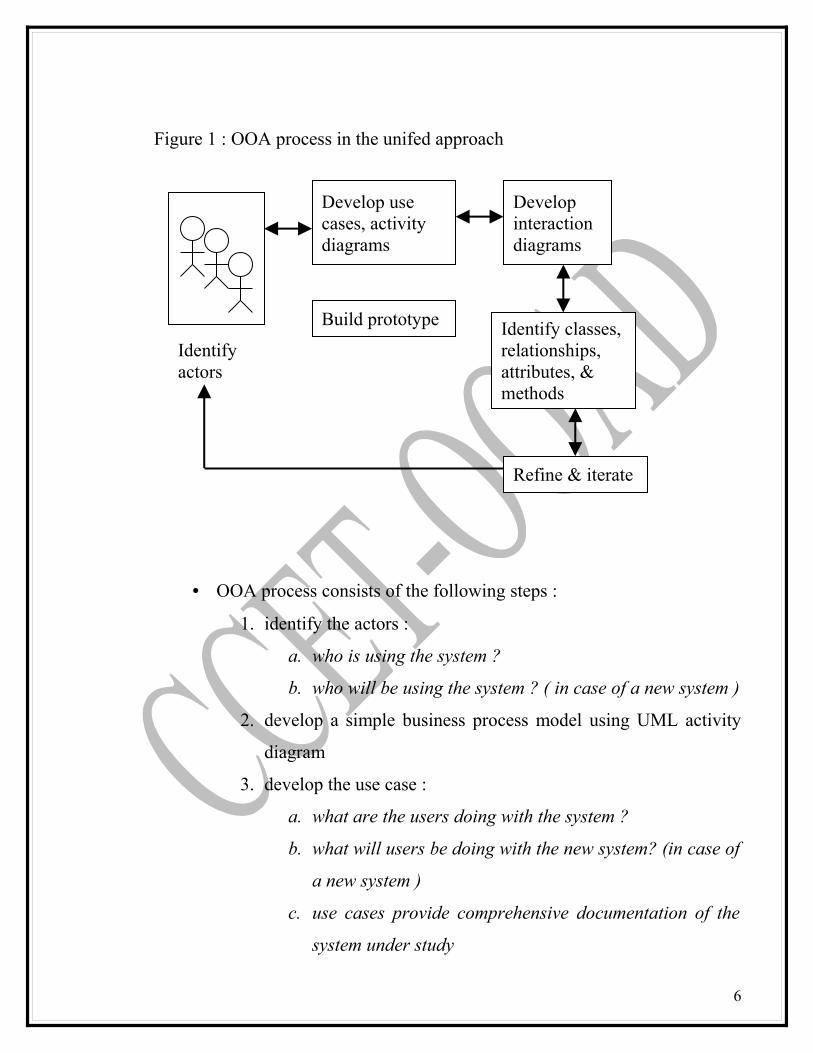
• OOA process consists of the following steps :
1. identify the actors :
a. who is using the system ?
b. who will be using the system ? ( in case of a new system )
2. develop a simple business process model using UML activity
diagram
3. develop the use case :
a. what are the users doing with the system ?
b. what will users be doing with the new system? (in case of
a new system )
c. use cases provide comprehensive documentation of the
system under study
6
Develop use cases, activity diagrams
Develop interaction diagrams
Build prototype
Refine & iterate
Identify classes, relationships, attributes, & methods
Identify actors
Figure 1 : OOA process in the unifed approach
4. prepare interaction diagrams
a. determine the sequence
b. develop collavboration diagrams
5. classification – develop a static UML class diagram :
a. identify classes
b. identify relationships
c. identify attributes
d. identify methods
6. iterate and refine : if needed, repeat the preceding steps
Business process modelling
• Not necessary for all project
• When required business process and requirements can be modelled to any
level of detail
• Activity diagram support this modelling
• disadvantages
– Time consuming process
• Advantages
– familiarity
7

Use case model
• Senarios for understanding the system
• Interaction bw user and system
• Captures users goal and systems responsibility
• Used to discover classes and relationship
• Developed by talking to users
• Use case model
– Provides external view of the system
• Object model (UML class diagram)
– Provides internal view
Use cases and microscope
• A use case is a sequence of transaction in a system whose task is to yield results of measurable value to an individual actor of the system
• Actor
Go to counter and
return books
Go to counter and check out the books
Interlibrary loan
Search for book
Do research on
topics
Read news paper and magazine
yes
Return book?
yesyes
yes
yes
yesyes
no
no
no
no
borrow book?
Do search
Read newspaper?
Activty diagram –library system
8
– Role played by the user with respect to the system– Single actor may perform many use cases– Can be external system– Can be one get value from the system, or just participate in the use
case
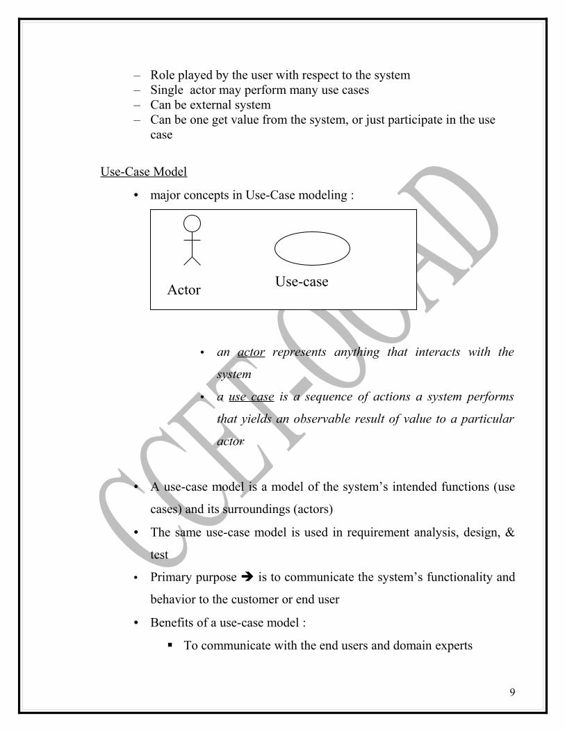
Use-Case Model
• major concepts in Use-Case modeling :
• an actor represents anything that interacts with the
system
• a use case is a sequence of actions a system performs
that yields an observable result of value to a particular
actor
• A use-case model is a model of the system’s intended functions (use
cases) and its surroundings (actors)
• The same use-case model is used in requirement analysis, design, &
test
• Primary purpose is to communicate the system’s functionality and
behavior to the customer or end user
• Benefits of a use-case model :
To communicate with the end users and domain experts
9
ActorUse-case
To identify :
• who will interact with the system and what the system
should do
• what interfaces the system should have
to verify :
• all requirements are captured
• that the developers have understood the requirements
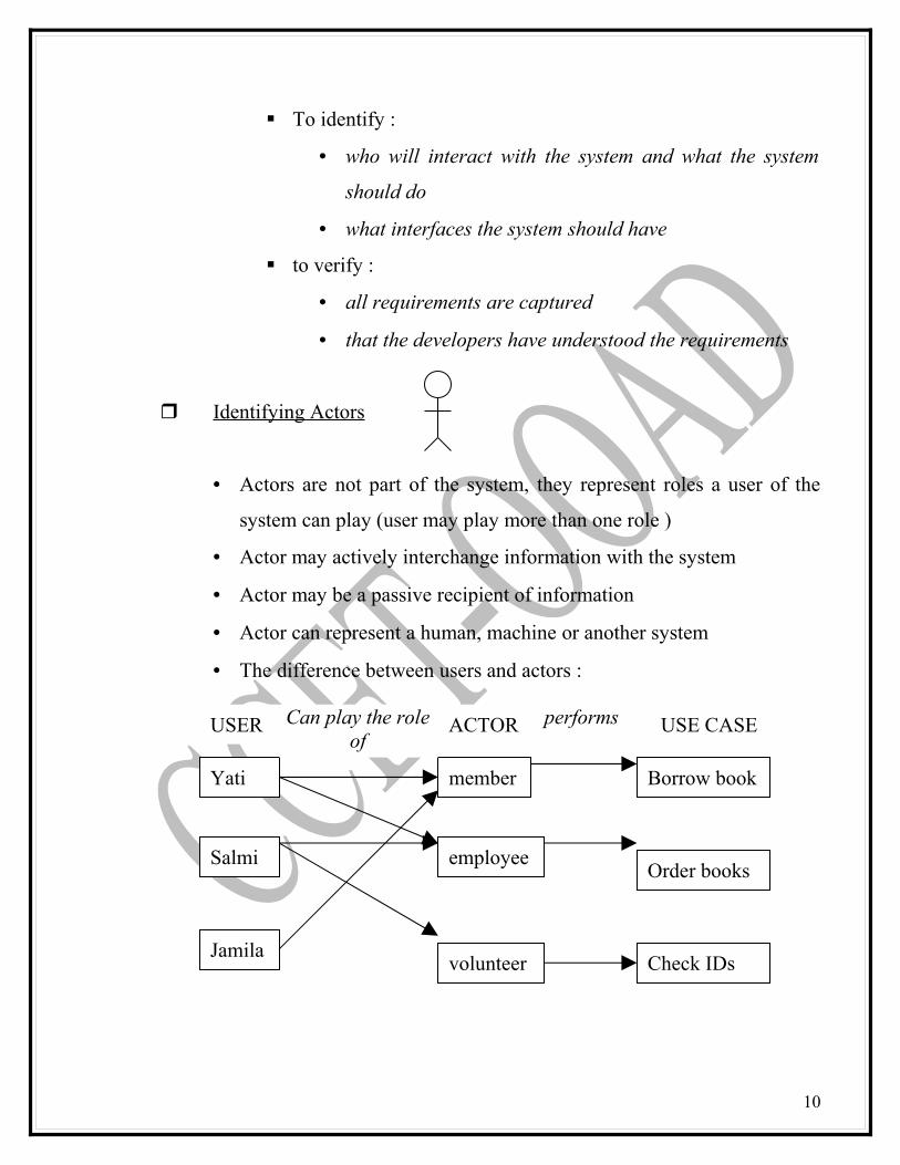
Identifying Actors
• Actors are not part of the system, they represent roles a user of the
system can play (user may play more than one role )
• Actor may actively interchange information with the system
• Actor may be a passive recipient of information
• Actor can represent a human, machine or another system
• The difference between users and actors :
10
Yati
Jamila
Salmi
USER
Borrow book
Check IDs
Order books
USE CASE
volunteer
employee
member
ACTORCan play the role of
performs
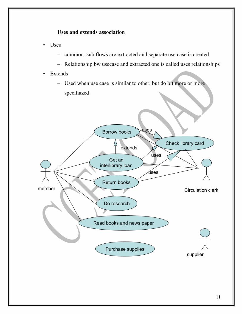
Uses and extends association
• Uses
– common sub flows are extracted and separate use case is created
– Relationship bw usecase and extracted one is called uses relationships
• Extends
– Used when use case is similar to other, but do bit more or more
speciliazed
Borrow books
Check library card
Get an interlibrary loan
Return books
Do research
Read books and news paper
Purchase supplies
member Circulation clerk
supplier
extends
uses
uses
uses
11
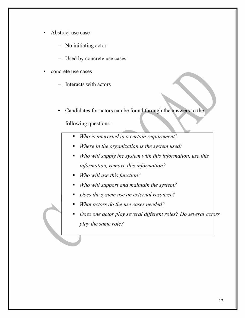
• Abstract use case
– No initiating actor
– Used by concrete use cases
• concrete use cases
– Interacts with actors
• Candidates for actors can be found through the answers to the
following questions :
Who is interested in a certain requirement?
Where in the organization is the system used?
Who will supply the system with this information, use this
information, remove this information?
Who will use this function?
Who will support and maintain the system?
Does the system use an external resource?
What actors do the use cases needed?
Does one actor play several different roles? Do several actors
play the same role?
12
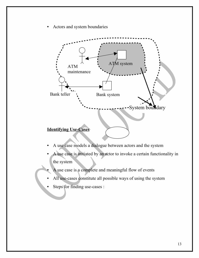
• Actors and system boundaries
Identifying Use-Cases
• A use case models a dialogue between actors and the system
• A use case is initiated by an actor to invoke a certain functionality in
the system
• A use case is a complete and meaningful flow of events
• All use-cases constitute all possible ways of using the system
• Steps for finding use-cases :
13
ATM system
Bank system
ATM maintenance
Bank teller
System boundary
For each actor, find the tasks and functions that the actor
should be able to perform or that the system needs the actor to
perform. The use case should represent a course of events that
leads to a clear goal
Name the use-cases
• Provide a general description of the use-case function
• The name should express what happens when an
instance of the use-case is performed
• Often expressed in the form of a verb (borrow) or verb
and noun (Borrow books)
Describe the use-cases briefly by applying terms with which the
user is familiar
• Sources of information for use-cases
System specification /problem statement
Domain relevant literature
Interviews with domain experts
Personal knowledge of the domain
Legacy systems
14
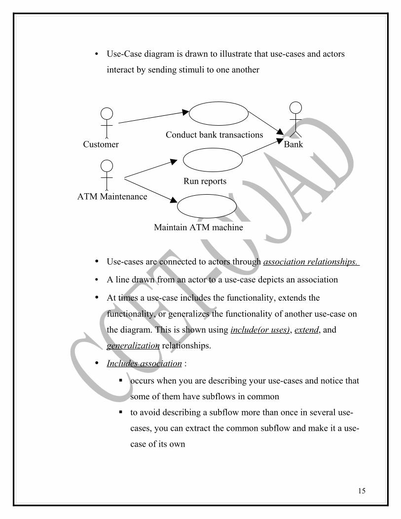
• Use-Case diagram is drawn to illustrate that use-cases and actors
interact by sending stimuli to one another
• Use-cases are connected to actors through association relationships.
• A line drawn from an actor to a use-case depicts an association
• At times a use-case includes the functionality, extends the
functionality, or generalizes the functionality of another use-case on
the diagram. This is shown using include(or uses), extend, and
generalization relationships.
• Includes association :
occurs when you are describing your use-cases and notice that
some of them have subflows in common
to avoid describing a subflow more than once in several use-
cases, you can extract the common subflow and make it a use-
case of its own
15
Conduct bank transactions
Maintain ATM machine
Run reports
ATM Maintenance
Customer Bank

represents the inclusion of the functionality of one use-case
within another
the arrow is drawn from the base use-case to the used use-case
• Extends association :
Used when you have one use-case that is similar to another use-
case BUT does a bit more, or is more specialized (like a
subclass)
Put the base or normal behavior in one use-case and the unusual
behaviors somewhere else
Represents the extension of the use-case to include optional
behavior
The arrow is drawn from the extension use-case to the base use-
case
• Generalization association :
Represents a specialized use-case to a more generalized one
More general use-case being higher than the lower use-cases
The arrow is drawn from the specialized use-case to the base
use-case
Refer to diagram, distribute in the class.
• Each use-case has to be described in a flow of events document. This
textual document defines what the system has to do when actor
activates a use-case.
• The structure of a use-case document can vary.
• Use-cases are documented in
16
• A brief description
o The purpose of the use-case in a few lines
• Detailed flow of events
o Description of the primary and alternate flow of
events that occur when the use-case is initiated
• Documentation should read like a dialogue between the
actor and the use-case
• Use-Case Flow of Events :
Each use-case :
• Has one normal, basic, sequence of transactions
• May have several alternative sequences of transactions
• Usually has several exceptional sequences of transactions
handling erroneous situations
• May also have well defined pre-and post-conditions
Describe only the events that belong to the use-case, and not
what happens in other use-cases
Avoid terminology such as “for example”, “etc.”, and “
information”
The flow of events should describe :• How and when the use-case starts and ends• When the use-case interacts with the actors• What information is excahnged between an actor and the
use-case ( do not describe the details of the user interface )
• The basic flow of events
17

• Any alternate flow of events
How detailed must a use case be? When to stop decomposing it and when
to continue
• Develop system use case diagram
• Draw package
– to represent business domains of the system . for each package
create child use case diagram
• Prepare at lest one scenario for each use case
– Each scenario shows different sequence of interaction , with all
decisions definite
• When the lowest use case level is arrived, which can’t be broken further,
sequence and collaboration diagram is drawn
Dividing use case into package
• Whole system is divided into many packages
• Each package encompasses multiple use cases
Refer to Use-Case Documentation example.
• Each use-case represent a scenario in the system• a design can be broken down into packages, and each of packages
consists multiple use-cases (refer to diagram , distribute in the class )
18
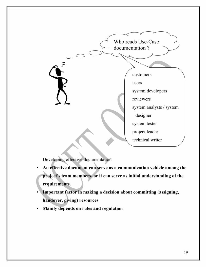
Developing effective documentation
• An effective document can serve as a communication vehicle among the
project's team members, or it can serve as initial understanding of the
requirements.
• Important factor in making a decision about committing (assigning,
handover, giving) resources
• Mainly depends on rules and regulation
19
Who reads Use-Case documentation ?
customers
users
system developers
reviewers
system analysts / system
designer
system tester
project leader
technical writer
Guidelines for developing effective documentation:
According to Bell and Evans:
• Common cover
• 80-20 rule
• Familiar vocabulary
• Make the document as short as possible
• Organize the document
1.Common Cover
• All documents should share a common cover sheet that identifies the
document, the current version, and the individual responsible for the
content.
2)80–20 Rule
• 80 percent of the work can be done with 20 percent of the documentation.
• The trick is to make sure that the 20 percent is easily accessible and the rest
(80 percent) is available to those (few) who need to know.
3)Familiar Vocabulary
• Use a vocabulary (word, language, expression) that your readers understand
and are comfortable with.
• The main objective here is to communicate with readers and not impress
them with buzz words.
4)Make the Document as Short as Possible
• Eliminate all repetition;
• Present summaries, reviews, organization chapters in less than three pages;
20
• Make chapter headings task (mission) oriented so that the table of
contents also could serve as an index (catalogue, guide,key).
•
5)Organize the Document
Use the rules of good organization (such as the organization's standards,
college handbooks, Strunk and White's Elements of Style, or the University
of Chicago Manual of Style) within each section.
SUMMARY
Analysis is the process of extracting the needs of a system and what the system must do to satisfy the users’ requirements.OOA phase of the unified approach uses actors and use cases to describe the system from users’ perspective.A use-case model is a model of the system’s intended functions (use cases) and its surroundings (actors).A use case models a dialogue between actors and the system.
KEY TERMSUse caseActorUse case modelKEY TERM QUIZ
1. A use-case model is a model of the system’s intended functions (use cases) and its surroundings (actors).2. Use cases are scenarios that describe how actors use the system.3. An actor represents anything that interacts with the system
MULTIPLE CHOICE
1. A use-case model is a model of the system’s intended functions (use cases) and its surroundings (actors). (a) Use case model (b) use cases2. Use cases are scenarios that describe how actors use the system. (a) Use case model (b) use cases3. An actor represents anything that interacts with the system (a) use case model (b) usecases (c) actor
21
REVIEW QUESTIONS
1. What is a use case model?2. Describe the basic activities in OO analysis?3. Who are actors?4. Why are uses and extends associations useful in use case modeling?5. How do you identify actors?6. What is 80-20 rule?
References :
Bahrami, A.(1999). Object Oriented Systems Development,
using the unified modeling language, McGraw-Hill
Object Oriented Analysis and Design using UML, by Rational
Software Corporation
Dennis,A., Wixon,B.H., and Tegarden,D.(2002). Systems Analysis and
Design : An Object Oriented Approach with UML
22
CHAPTER 5:
OBJECT ANALYSIS – CLASSIFICATION
OBJECTIVES :
At the end of this chapter, students should be able to
• Identify classes using the noun phrase strategy• Identify classes using the common class pattern strategy• Identify classes using the CRC strategy• Identify classes using the use case analysis strategy• Identify attributes and methods for classes• Identify relationships between classes• Develop the interaction diagrams (sequence and collaboration diagrams)• Develop the class diagram
23

INTRODUCTION:
Object Analysis : Classification
• Identification of classes is the hardest part of part of OOAnalysis
• Object analysis a process by which we can identify the classes that
play role a role in achieving the system goals & requirements
• Booch states that “ There is no such a thing as the perfect class
structure, nor the right set of objects”
• Classification the categorization of input data (things) into identifiable classes through the extraction of significant features of attributes of the data from a background of irrelevant detail
• Classes are an important mechanism for classifying objects
• The main role of a class is to define the attributes, methods, and applicability of its instances
24
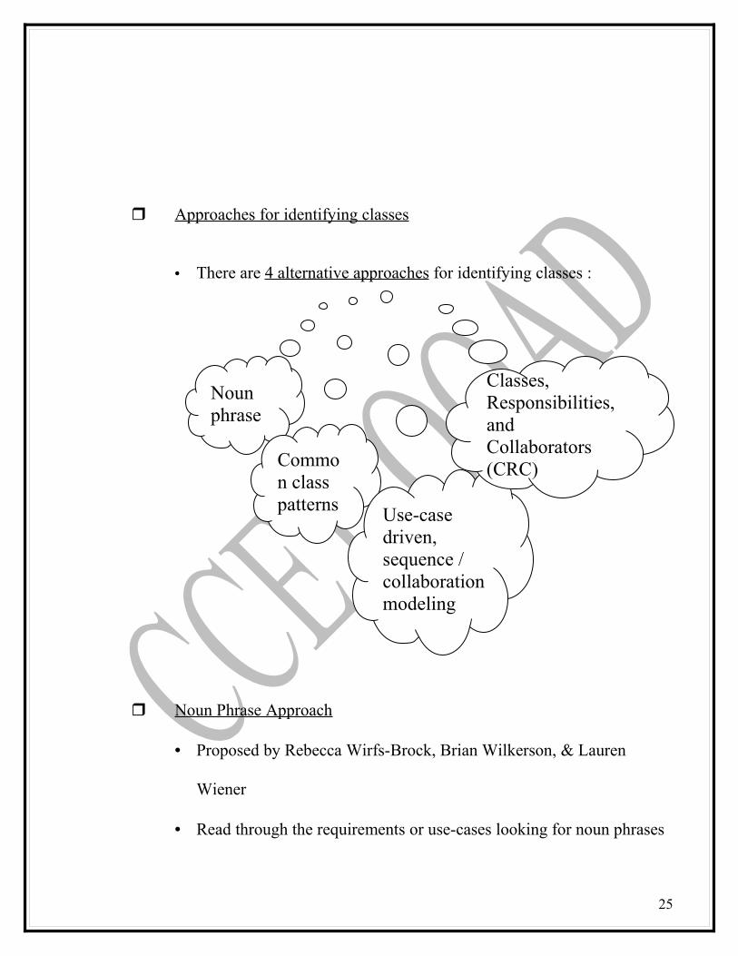
Approaches for identifying classes
• There are 4 alternative approaches for identifying classes :
Noun Phrase Approach
• Proposed by Rebecca Wirfs-Brock, Brian Wilkerson, & Lauren
Wiener
• Read through the requirements or use-cases looking for noun phrases
25
Noun phrase
Common class patterns Use-case
driven, sequence / collaboration modeling
Classes, Responsibilities, and Collaborators (CRC)

• Nouns are listed and divided into 3 categories :
• Guidelines for selecting classes in an application :
26
Nouns in textual description
Classes
Verbs in textual description
Methods of the classes
Considered to be
Considered to be
plurals singularChanged to
Relevant classes
Irrelevant classes
fuzzy classes
Scrap this classes, which either have no purpose or will be unnecessary
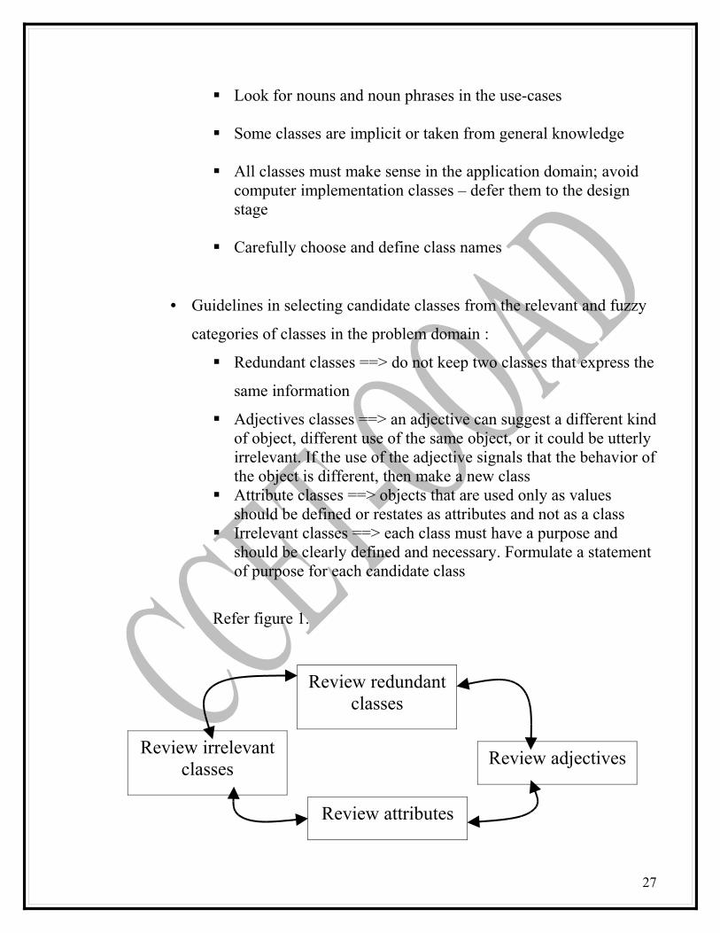
Look for nouns and noun phrases in the use-cases
Some classes are implicit or taken from general knowledge
All classes must make sense in the application domain; avoid computer implementation classes – defer them to the design stage
Carefully choose and define class names
• Guidelines in selecting candidate classes from the relevant and fuzzy
categories of classes in the problem domain :
Redundant classes ==> do not keep two classes that express the
same information
Adjectives classes ==> an adjective can suggest a different kind of object, different use of the same object, or it could be utterly irrelevant. If the use of the adjective signals that the behavior of the object is different, then make a new class
Attribute classes ==> objects that are used only as values should be defined or restates as attributes and not as a class
Irrelevant classes ==> each class must have a purpose and should be clearly defined and necessary. Formulate a statement of purpose for each candidate class
Refer figure 1.
27
Review redundant classes
Review irrelevant classes
Review attributes
Review adjectives
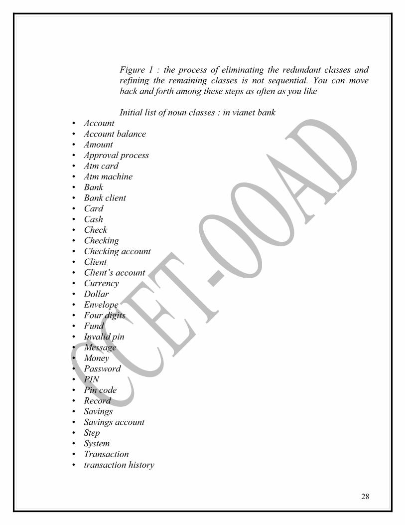
Figure 1 : the process of eliminating the redundant classes and refining the remaining classes is not sequential. You can move back and forth among these steps as often as you like
Initial list of noun classes : in vianet bank• Account• Account balance• Amount• Approval process• Atm card• Atm machine• Bank• Bank client• Card• Cash• Check• Checking• Checking account• Client• Client’s account• Currency• Dollar• Envelope• Four digits• Fund• Invalid pin• Message• Money• Password• PIN• Pin code• Record• Savings• Savings account• Step• System• Transaction• transaction history
28
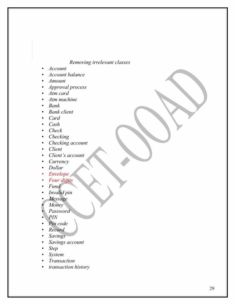
Removing irrelevant classes• Account• Account balance• Amount• Approval process• Atm card• Atm machine• Bank• Bank client• Card• Cash• Check• Checking• Checking account• Client• Client’s account• Currency• Dollar• Envelope• Four digits• Fund• Invalid pin• Message• Money• Password• PIN• Pin code• Record• Savings• Savings account• Step• System• Transaction• transaction history
29

Removing redundant classes and building common vocabulary
AccountAccount balanceAmountApproval processAtm cardAtm machineBankBank clientCardCashCheckCheckingChecking account
ClientClient’s accountCurrencyDollarEnvelopeFour digitsFundInvalid pinMessageMoneyPasswordPINPin code
RecordSavingsSavings accountStepSystemTransactiontransaction history
30

Reviewing the class purpose
Include classes with• Purpose• Clear definition • Necessary in achieving system goal
Eliminate classes with no purpose Ex: Candidate class with purpose are
• ATM machine class• ATM card class• Bankclient class• Bank class• Account class• Checking account class
AccountAccount balanceAmountApproval processAtm cardAtm machineBankBank clientCardCashCheckCheckingChecking account
ClientClient’s accountCurrencyDollarEnvelopeFour digitsFundInvalid pinMessageMoneyPasswordPINPin code
RecordSavingsSavings accountStepSystemTransactiontransaction
history
Reviewing possible attributes
31
• Saving account class• Transaction class
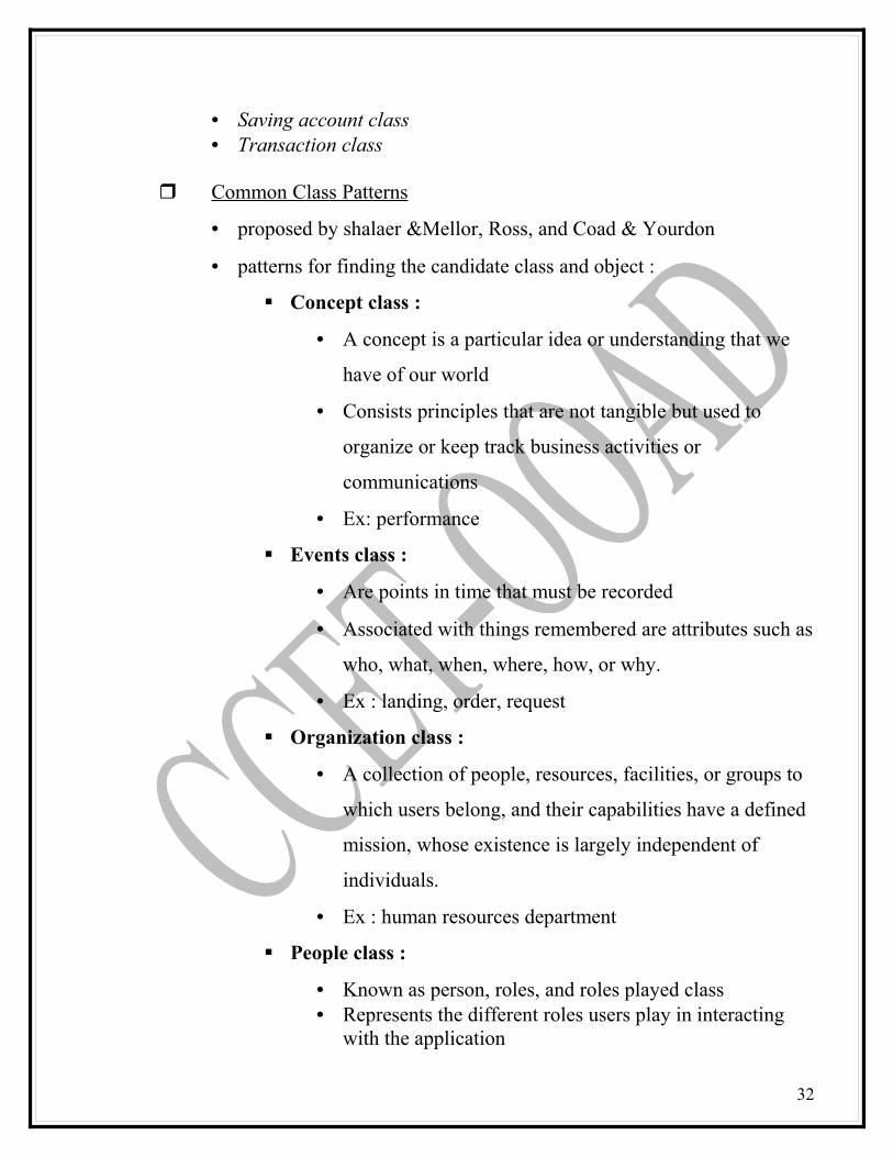
Common Class Patterns
• proposed by shalaer &Mellor, Ross, and Coad & Yourdon
• patterns for finding the candidate class and object :
Concept class :
• A concept is a particular idea or understanding that we
have of our world
• Consists principles that are not tangible but used to
organize or keep track business activities or
communications
• Ex: performance
Events class :
• Are points in time that must be recorded
• Associated with things remembered are attributes such as
who, what, when, where, how, or why.
• Ex : landing, order, request
Organization class :
• A collection of people, resources, facilities, or groups to
which users belong, and their capabilities have a defined
mission, whose existence is largely independent of
individuals.
• Ex : human resources department
People class :
• Known as person, roles, and roles played class• Represents the different roles users play in interacting
with the application
32
• What role does a person play in the system ?• Ex : employee, student, lecturer
Places class :
• Physical locations that the system must keep information
about
• Ex : buildings, stores, offices
Tangible things and devices class :
• Includes physical objects or groups of objects that are
tangible and devices with which the application interacts
• Ex : car (tangible ), pressure sensors (devices)
Classes, Responsibilities, and Collaborators (CRC)
• Developed by Cunningham, Wilkerson, and Beck presented as a
way of teaching the basic concepts of OO development
• CRC a technique used for identifying classes’ responsibilities and
therefore their attributes and methods
• Assists in identifying classes
• Based on the idea that an object either can accomplish a certain
responsibility itself or it may require the assistance of other objects
33
Then it must collaborate with those objects to fulfill its responsibility
• By identifying an object’s responsibilities and collaborators, you can
identify its attributes and methods
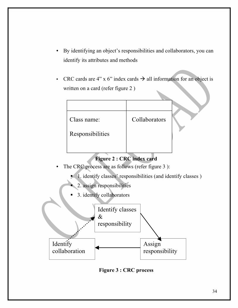
• CRC cards are 4” x 6” index cards all information for an object is
written on a card (refer figure 2 )
Figure 2 : CRC index card
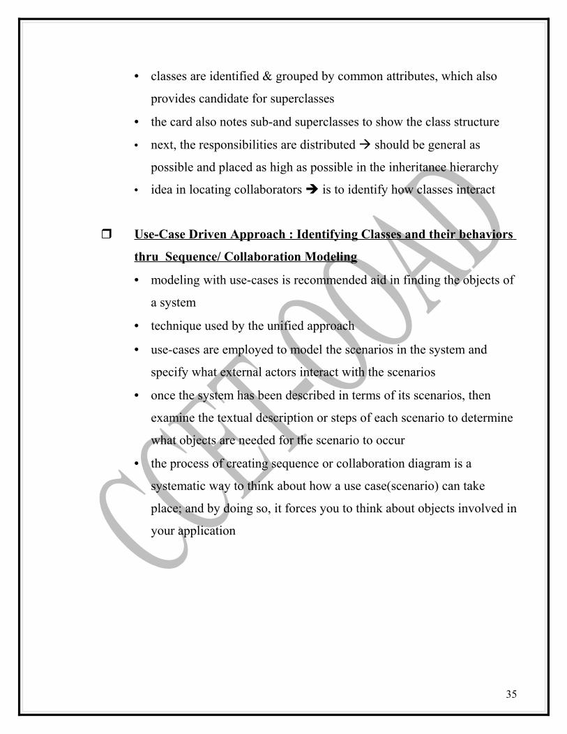
• The CRC process are as follows (refer figure 3 ):
1. identify classes’ responsibilities (and identify classes )
2. assign responsibilities
3. identify collaborators
Figure 3 : CRC process
34
Class name: Collaborators
Responsibilities
Identify classes & responsibility
Identify collaboration
Assign responsibility
• classes are identified & grouped by common attributes, which also
provides candidate for superclasses
• the card also notes sub-and superclasses to show the class structure
• next, the responsibilities are distributed should be general as
possible and placed as high as possible in the inheritance hierarchy
• idea in locating collaborators is to identify how classes interact
Use-Case Driven Approach : Identifying Classes and their behaviors
thru Sequence/ Collaboration Modeling
• modeling with use-cases is recommended aid in finding the objects of
a system
• technique used by the unified approach
• use-cases are employed to model the scenarios in the system and
specify what external actors interact with the scenarios
• once the system has been described in terms of its scenarios, then
examine the textual description or steps of each scenario to determine
what objects are needed for the scenario to occur
• the process of creating sequence or collaboration diagram is a
systematic way to think about how a use case(scenario) can take
place; and by doing so, it forces you to think about objects involved in
your application
35
• Use Case analysis the process of examining use cases to discover
objects and classes for the system being developed
Scenarios are detailed and shown graphically in interaction
diagrams
Classes are grouped into packages
Class diagrams are created
• Purpose
identify the classes which perform a use case’s flow of events
distribute the use case behavior to those classes, using a use-
case realizations
identify the responsibilities, attributes, and associations of the
classes
36
What is use case analysis ?
• Use-Case Realization :
A use case realization desribes how a particular use case is
realized within the Design Model in terms of collaborating
objects
A use case realization in the Design model can be traced to a
use case in the Use Case model.
A realization realtionship is drawn from the use case
realization to the use-case it realizes
• A use-case realization can be presented using a set of diagrams :
Interaction diagrams (sequence and/or collaboration
diagrams) can be used to describe how the use case is realized
in terms of collaborating objects. These diagrams model the
detailed collaborations of the use-case realization.
Class diagrams can be used to describe the classes that
participate in the realization of the use-case, as well as their
supporting relationships. These diagrams model the context of
the use-case realization
37
Use case model Design model
Use case Use case realization
• For each use case realization :
Find classes from use-case behavior
Distribute use-case behavior to classes
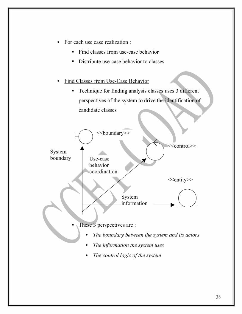
• Find Classes from Use-Case Behavior
Technique for finding analysis classes uses 3 different
perspectives of the system to drive the identification of
candidate classes
These 3 perspectives are :
• The boundary between the system and its actors
• The information the system uses
• The control logic of the system
38
System boundary
System information
Use-case behavior coordination
<<boundary>>
<<control>>
<<entity>>
Identification of classes means just that : they should be
identified, named, and described briefly in a few sentences
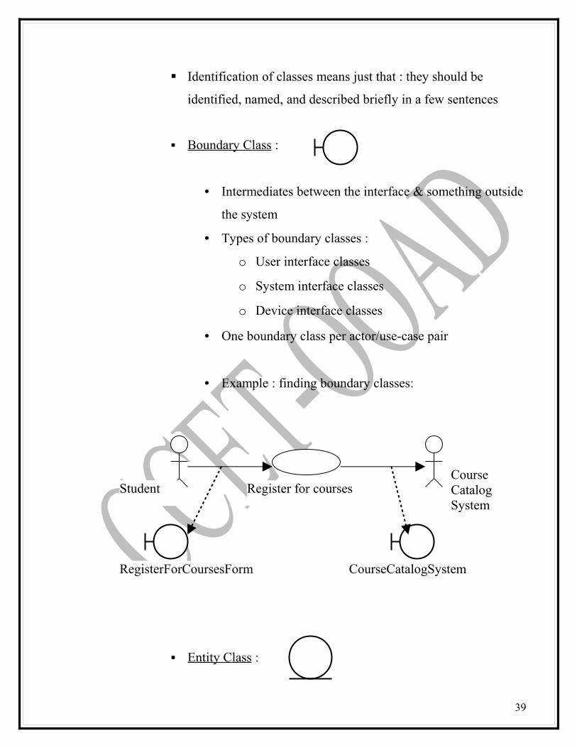
Boundary Class :
• Intermediates between the interface & something outside
the system
• Types of boundary classes :
o User interface classes
o System interface classes
o Device interface classes
• One boundary class per actor/use-case pair
• Example : finding boundary classes:
Entity Class :
39
Register for courses
RegisterForCoursesForm CourseCatalogSystem
Course Catalog System
Student
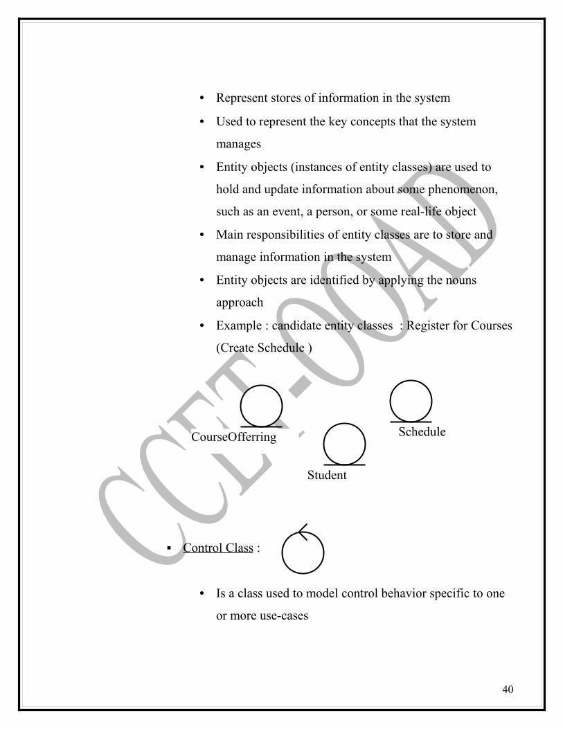
• Represent stores of information in the system
• Used to represent the key concepts that the system
manages
• Entity objects (instances of entity classes) are used to
hold and update information about some phenomenon,
such as an event, a person, or some real-life object
• Main responsibilities of entity classes are to store and
manage information in the system
• Entity objects are identified by applying the nouns
approach
• Example : candidate entity classes : Register for Courses
(Create Schedule )
Control Class :
• Is a class used to model control behavior specific to one
or more use-cases
40
CourseOfferring
Student
Schedule

• They represent the dynamics of the system, handling the
main tasks and control flows
• One control class per use case
• Example : finding control classes
• Each control class is responsible for controlling the
processing that implements the functionality described in
the associated use case.
• Naming Classes
A class name should be a singular noun
Class names start with an upper case letter
Underscores are not used
• Names composed of multiple words are pushed together
and the first letter of each additional word is capitalized
41
Register for courses
RegistrationController
Course Catalog System
Student
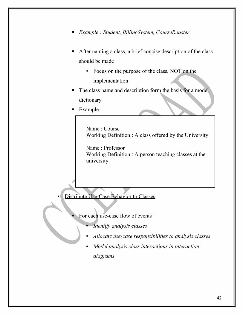
Example : Student, BillingSystem, CourseRoaster
After naming a class, a brief concise description of the class
should be made
• Focus on the purpose of the class, NOT on the
implementation
The class name and description form the basis for a model
dictionary
Example :
Name : CourseWorking Definition : A class offered by the University
Name : ProfessorWorking Definition : A person teaching classes at the university
• Distribute Use-Case Behavior to Classes
For each use-case flow of events :
• Identify analysis classes
• Allocate use-case responsibilities to analysis classes
• Model analysis class interactions in interaction
diagrams
42
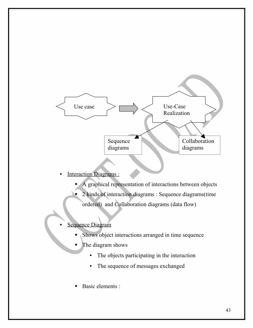
• Interaction Diagrams :
A graphical representation of interactions between objects
2 kinds of interaction diagrams : Sequence diagrams(time
ordered) and Collaboration diagrams (data flow)
• Sequence Diagram
Shows object interactions arranged in time sequence
The diagram shows
• The objects participating in the interaction
• The sequence of messages exchanged
Basic elements :
43
Use case Use-Case Realization
Sequence diagrams
Collaboration diagrams

• Actors : someone/something outside the system that
interacts with the system, either by giving or receiving
information, or both
• Objects: an entity with a well-defined boundary and
identity that encapsulates state and behavior
44
Math 101 Math 101 :
CourseOffering
: CourseOffering
Object nameObject name and Class name
Class name
Object representation in UML

• Messages: communication between two objects that
triggers an event
• Lifelines :represents the existence of the object at a
particular time
• Focus of control :shows the period of time during which
an object is performing an action, either directly or
through a subordinate procedure
• Collaboration Diagram
45
Message
:Prospective Buyer :PersonalPlannerForm
//maintain profile()
//prompt to create new profile()
:Prospective Buyer :PersonalPlannerForm
//maintain profile()
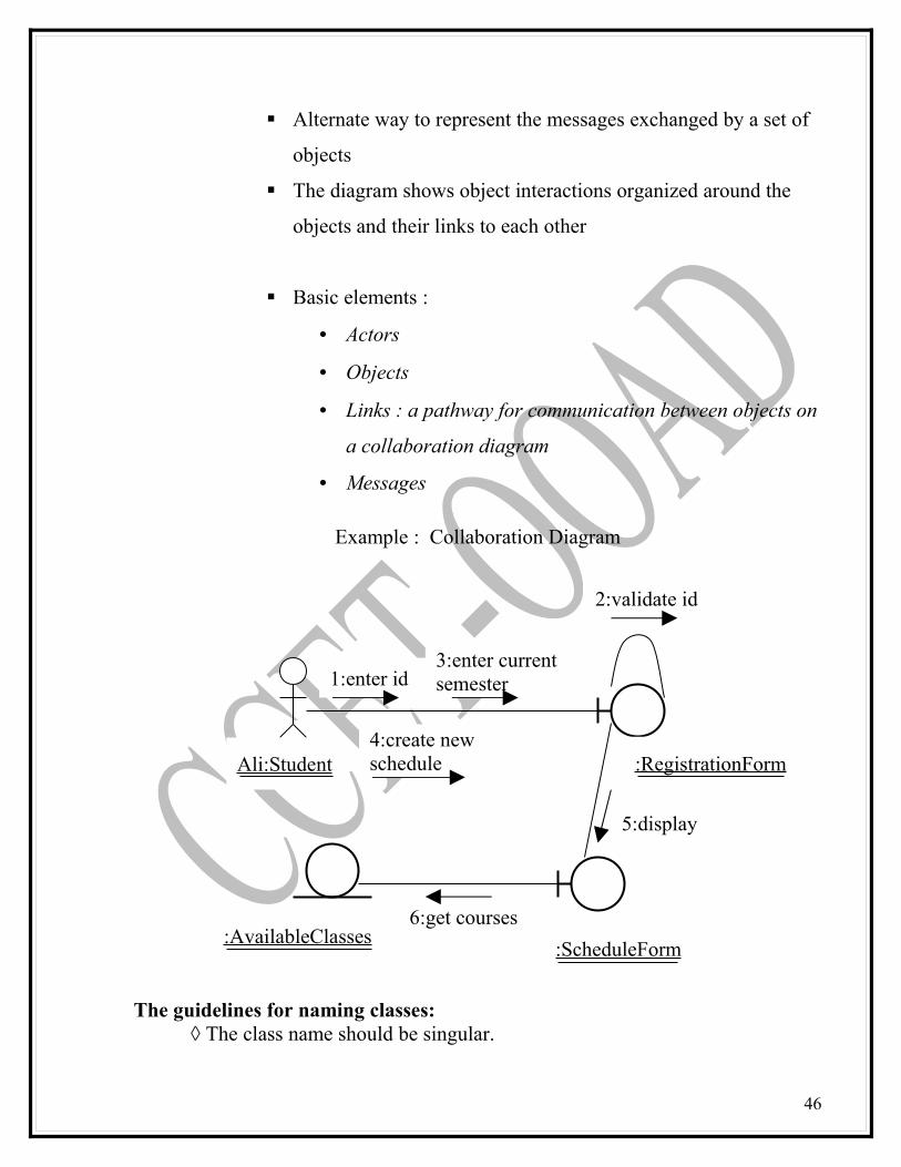
Alternate way to represent the messages exchanged by a set of
objects
The diagram shows object interactions organized around the
objects and their links to each other
Basic elements :
• Actors
• Objects
• Links : a pathway for communication between objects on
a collaboration diagram
• Messages
Example : Collaboration Diagram
The guidelines for naming classes: ◊ The class name should be singular.
46
1:enter id
2:validate id
3:enter current semester
4:create new schedule
5:display
6:get courses
Ali:Student
:AvailableClasses:ScheduleForm
:RegistrationForm
◊ One general rule for naming classes is that you should use names with which the users or clients are comfortable. ◊ The name of a class should reflect its intrinsic nature. ◊ Use readable name. Capitalize class names.
SUMMARY:
Identification of classes is the hardest part of part of OOAnalysis.Classification is the categorization of input data (things) into identifiable classes through the extraction of significant features of attributes of the data from a background of irrelevant detail. The guidelines for naming classes- The class name should be singular, One general rule for naming classes is that you should use names with which the users or clients are comfortable, the name of a class should reflect its intrinsic nature., Use readable name, Capitalize class names.
KEYTERMS
Classes ,Responsibilities, and Collaborators (CRC)ClassificationConcept classPlaces classOrganization classPerson class (or) people classTangible things and devices class
KEY TERM QUIZ
1. Concept class concept is a particular idea or understanding that we have of our world
2. Events class is points in time that must be recorded3. Organization class is a collection of people, resources, facilities, or groups
to which users belong, and their capabilities have a defined mission, whose existence is largely independent of individuals.
4. People class is Known as person, roles, and roles played class5. Places class is a physical locations that the system must keep information
about6. Tangible things and devices class which includes physical objects or
groups of objects that are tangible and devices with which the application interacts
47
7. Classes ,Responsibilities, and Collaborators (CRC) is a technique used for identifying classes’ responsibilities and therefore their attributes and methods
8. Classification is the categorization of input data (things) into identifiable classes through the extraction of significant features of attributes of the data from a background of irrelevant detail.
MULTIPLE CHOICE
1. Concept class concept is a particular idea or understanding that we have of our world
(a) concept class (b) event class (c) organization class (d) people class2. Events class is points in time that must be recorded (a) concept class (b) event class (c) organization class (d) people class3. Organization class is a collection of people, resources, facilities, or groups
to which users belong, and their capabilities have a defined mission, whose existence is largely independent of individuals.
(a) concept class (b) event class (c) organization class (d) people class4. People class is Known as person, roles, and roles played class (a) concept class (b) event class (c) organization class (d) people class5. Places class is a physical locations that the system must keep information
about (a)Places class (b) event class (c) organization class (d) people class6. Tangible things and devices class which includes physical objects or
groups of objects that are tangible and devices with which the application interacts
(a) concept class (b) event class (c) organization class (d) Tangible things and devices class
7. Classes ,Responsibilities, and Collaborators (CRC) is a technique used for identifying classes’ responsibilities and therefore their attributes and methods(a) CRC (B) classification
8. Classification is the categorization of input data (things) into identifiable classes through the extraction of significant features of attributes of the data from a background of irrelevant detail.
(a) CRC (B) classification
REVIEW QUESTIONS
48
1. What are the approaches to identify classes?2. Describe the noun phrase strategy for identifying tentative classes in the problem domain?3. Describe relevant, fuzzy, irrelevant classes.4. How do you select candidate classes from the list of relevant and fuzzy classes?5. Why is identifying classes an incremental process?6. Why is developing a sequence / collaboration diagram a useful activity in identifying classes?7. Mention the uses of CRC8. Why is identifying class hierarchy important in OO analysis?
49
CHAPTER-8
Identify Objects, Relationships, Attributes, Methods
OBJECTIVES:
At the end of this chapter, students should be able to define and understand:
• Analyzing relationship among classes• Identifying association• Association patterns• Class responsibilities
INTRODUCTION
The three types of relationships among objects are Association, Super-Sub structure (also known as generalization hierarchy), Aggregation and a-part-of structure. Association represents a physical or conceptual connection between two or more objects. Binary associations are shown as lines connecting two class symbols. Ternary and higher-order associations are shown as diamonds connecting to a class symbol by lines, and the association name is written above or below the line. We need to identify the system’s responsibilities because responsibilities identify problems that are to be solved. A responsibility serves as a handle for discussing potential solutions. Once the system’s responsibilities are understood, we can start identifying the attributes of the system’s classes.
50

Relationships
• All objects stand in relationship to others on whom they rely for
services and control
• The relationship among objects is based on the assumptions each
makes about the other objects, including what operations can be
performed and what behavior results
• 3 types of relationships among objects :
Association
Super-Sub structure (also known as generalization hierarchy)
Aggregation and a-part-of structure
• ASSOCIATION :
Represents a physical or conceptual connection between two or
more objects
The most general relationship and indicate communication only
Ex : if an object has the responsibility for telling another object
that a credit card number is valid or invalid, the two classes
have an association
Identifying associations begins by analyzing the interactions
between classes
Any dependency relationship between two or more classes is an
association
Examine the responsibilities to determine dependencies
51

The following questions can assists in identifying associations
[Wirfs-Brock, Wilkerson, &Wiener ]:
• Is the class capable of fulfilling the required task by
itself?
• If Not, what does it need ?
• From what other class can it acquire what it needs ?
Association Specifiers
• association names a label that clarifies the meaning of
the association
o usually verbs or verb phrase
o use either an association or a role name, NOT
both
o used during analysis, before sufficient information
exists to use role names
• role names a label that specifies the ‘face’ the class
plays in an association
o usually noun or noun phrase
o use either a role name , or an association name,
NOT both
o roles name are preferable, when information is
available
o always be used during design
52
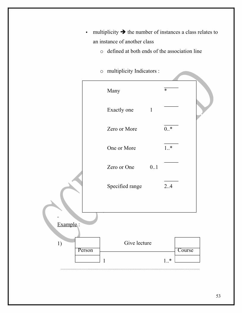
• multiplicity the number of instances a class relates to
an instance of another class
o defined at both ends of the association line
o multiplicity Indicators :
Many *
Exactly one 1
Zero or More 0..*
One or More 1..*
Zero or One 0..1
Specified range 2..4
Example :
1)
53
1
Person CourseGive lecture
1..*

2)
• SUPER-SUB CLASS RELATIONSHIPS (GENERALIZATION)
A class is part of hierarchy of classes, where the top class is the
most general one and from it descend all other, more
specialized classes
Represents the inheritance relationships between related classes
Also known as generalization hierarchy
Advantage can build on what already have and more
important, reuse what already have
Inheritance allows classes to share and reuse behaviors and
attributes
Example : Generalization hierarchy
• AGGREGATION (A-APRT-OF RELATIONSHIPS) :
54
StaffMemberStaffNameStaffNoCalculateBonusChachangeGradegetGrade
CreativeStaffAdminStaff
1
Person CourseLecturer
1..*
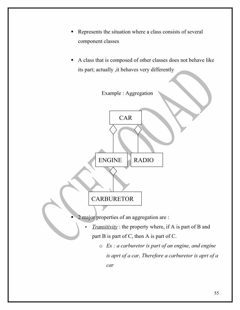
Represents the situation where a class consists of several
component classes
A class that is composed of other classes does not behave like
its part; actually ,it behaves very differently
Example : Aggregation
2 major properties of an aggregation are :
• Transitivity : the property where, if A is part of B and
part B is part of C, then A is part of C.
o Ex : a carburetor is part of an engine, and engine
is aprt of a car, Therefore a carburetor is aprt of a
car
55
CAR
CARBURETOR
RADIOENGINE
• Antisymmetry : the property where, if A is part of B, then
B is not part of A.
o Ex : An engine is aprt of car, BUT car is not part
of an engine
Identifying Attributes
• attributes are things an object must remember
• an attribute is a data definition held by instances of a class (object)
• attributes do not have behavior they are NOT objects
• attribute are simple nouns or noun phrases
names must be unique within a class
• each attribute should have a clear, concise definition
• Example :
• Good attributes for the STUDENT class :
o Name : first and last name
o Major : major field of study
• Bad attribute for the STUDENT class :
o SelectedCourses
[ This is a relationship NOT an attribute ]
• An attribute value is the value of an attribute for a particular object
• Each object has a value for every attribute defined for its class
56
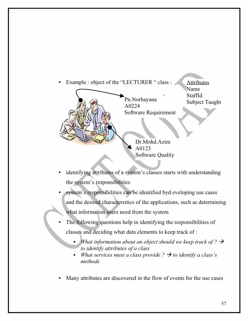
• Example : object of the “LECTURER “ class :
• identifying attributes of a system’s classes starts with understanding
the system’s responsibilities
• system’s responsibilities can be identified byd eveloping use cases
and the desired charactersitics of the applications, such as determining
what information users need from the system
• The following questions help in identifying the responsibilities of
classes and deciding what data elements to keep track of :
What information about an object should we keep track of ? to identify attributes of a class
What services must a class provide ? to identify a class’s methods
• Many attributes are discovered in the flow of events for the use cases
57
AttributesNameStaffIdSubject Taught
Dr.Mohd.AzimA0123Software Quality
Pn.NorhayanaA0224Software Requirement
• Look for nouns that were not considered good candidate
classes
• Others are discovered when the class definition is created
Identifying Methods/operation
• Objects not only describe abstract data but also must provide some
services
• In an object-oriented environment, every piece of data, or object is
surrounded by a rich set of rountines called methods. ( These methods
do everything from printing the object to initializing its variables )
• Operations (methods or behavior) in the object-oriented system
usually correspond to queries about attributes (and sometimes
association) of the objects
• An operation is a service that can be requested from an object to
effect behavior
• Methods are responsible for managing the value of attributes such as
query, updating, reading, and writing;
Example : operation GetBalance, return the value of an account’s
balance
58
• Operation should be name to indicate their outcome NOT the steps
behind the operation
Example :
calculateBalance ( ) poorly namedIt indicates the balance must be calculated this is an implementation decision
GetBalance ( ) Well namedIt indicates the outcome only
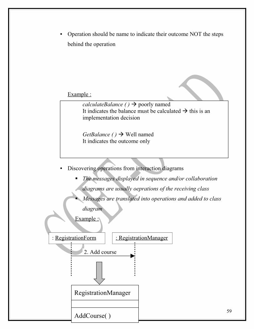
• Discovering operations from interaction diagrams
The messages displayed in sequence and/or collaboration
diagrams are usually oeprations of the receiving class
Messages are translated into operations and added to class
diagram
Example :
59
2. Add course
: RegistrationForm : RegistrationManager
RegistrationManager
AddCourse( )
Class Diagram
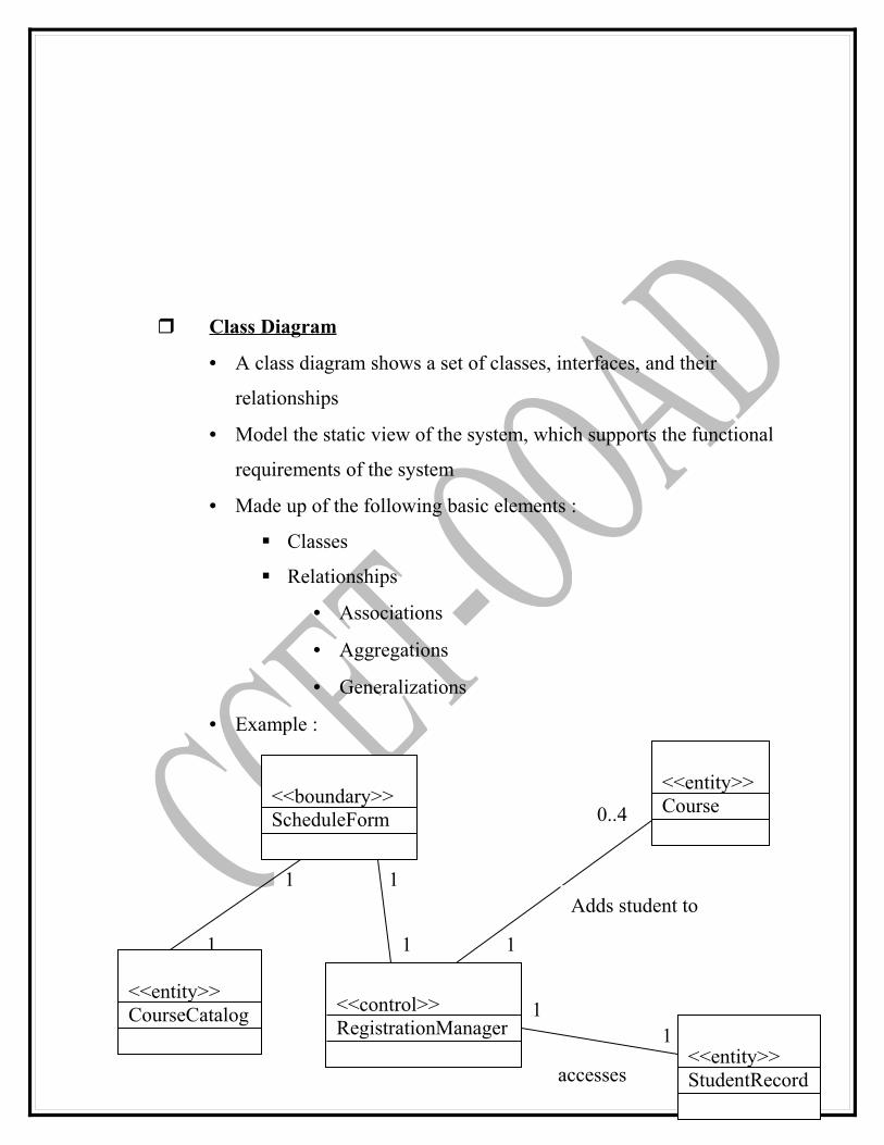
• A class diagram shows a set of classes, interfaces, and their
relationships
• Model the static view of the system, which supports the functional
requirements of the system
• Made up of the following basic elements :
Classes
Relationships
• Associations
• Aggregations
• Generalizations
• Example :
60
1 1
0..4
1
1
1
1
1
<<boundary>>ScheduleForm
<<entity>>CourseCatalog
<<entity>>StudentRecord
<<entity>>Course
<<control>>RegistrationManager
Adds student to
accesses
SUMMARY
The three types of relationships among objects are Association, Super-Sub structure (also known as generalization hierarchy), Aggregation and a-part-of structure. Association represents a physical or conceptual connection between two or more objects. Binary associations are shown as lines connecting two class symbols. Ternary and higher-order associations are shown as diamonds connecting to a class symbol by lines, and the association name is written above or below the line. We need to identify the system’s responsibilities because responsibilities identify problems that are to be solved. A responsibility serves as a handle for discussing potential solutions. Once the system’s responsibilities are understood, we can start identifying the attributes of the system’s classes. A-part-of relationship, also called aggregation, represents the situation where a class consists of several component classes. A class that is composed of other classes does not behave like its parts; actually, it behaves very differently.
KEY TERMS
AggregationAntisymmetryA part of relationshipAssociationTransitivity
KEY TEM QUIZ
1. ASSOCIATION represents a physical or conceptual connection between two or more objects
2. AGGREGATION (A-APRT-OF RELATIONSHIPS) represents the situation where a class consists of several component classes
61

3. Transitivity is the property where, if A is part of B and part B is part of C, then A is part of C.
4. Antisymmetry is the property where, if A is part of B, then B is not part of A.
MULTIPLE CHOICE
1. ASSOCIATION represents a physical or conceptual connection between two or more objects
(a) Association (b) Aggregation2. AGGREGATION (A-APRT-OF RELATIONSHIPS) represents the
situation where a class consists of several component classes (a) Association (b) Aggregation3. Transitivity is the property where, if A is part of B and part B is part of C,
then A is part of C. (a)Transitivity (b) Antisymmetry4. Antisymmetry is the property where, if A is part of B, then B is not part of
A. (a)Transitivity (b) Antisymmetry
REVIEW QUESTIONS
1. What is association?2. What is generalization?3. How would you identify a super- subclass structure?4. What is an a-part-of structure? Write their properties.5. What guidelines would you use to identify a-part-of structure?6. Is association different from an a-part-of relation?7. What are unnecessary associations? How would you know?8. How do you identify attributes?9. How do you identify methods?10. What are the unnecessary attributes?11. Why do we need to justify classes with one attribute?12. State why documentation is important part of analysis.
62
13. What are the similarities between classes and Use Cases?14. State the difference between the classes and Use Cases.
References :
Bahrami, A.(1999). Object Oriented Systems Development, using the unified modeling language, McGraw-Hill
Object Oriented Analysis and Design using UML, by Rational Software Corporation (2002)
63