unit – i - chettinadtech.ac.inchettinadtech.ac.in/storage/13-07-13/13-07-13-13-01-04-2183... ·...
TRANSCRIPT

1
UNIT – I LATHE

2

3
INTRODUCTION:
Lathe is the father of all machine tool. It is a basic machine tool probably the most important
one of all, lathe was actually the first machine tool.
Lathe is a particular type of machine tool in which the work is held and rotated against a
suitable cutting tool for the purpose of producing surface of revolution in any material.
LATHE SPECIFICATIONS:
In order to specify a lathe, a number of parameters could be used on the specific
applications. However, the major elements used for specifications should invariably be based on
the components that would be manufactured in the lathe. The sum of lathe specifications is,
L=Distance between centers. A=Swing diameter over bed. B=Swing diameter over carriage. R=Radius. H=Height of center from bed
DISTANCE BETWEEN CENTERS (L):
This would be specifying the maximum length of the job that can be turned in the lathe.
SWING DIAMETER OVER BED (A):
This specifies the maximum diameter of the job that can be turned in the lathe machine
generally restricted to small length jobs.
SWING DIAMETER OVER CARRIAGE (B):
This specifies the maximum diameter of job that can be turned in the lathe machines with the
job across the cross slide.
Manufacturing Technology Lab - I Manual

4
Manufacturing Technology Lab - I Manual

5
Other factors should also be specified to fully describe the lathe machine.
1. Horse power of the motor
2. Feed range
3. Accuracy achieved
4. Cutting speed range
5. Screw cutting capacity
6. Spindle nose diameter
PARTS OF ENGINE LATHE OR CENTER LATHE:
The principal parts of an engine lathe are,
1. Bed,
2. Head stock,
3. Tail stock,
4. Carriage,
4.1. Saddle,
4.2. Cross slide,
4.3. Compound rest,
4.4. Tool post,
4.5. Apron.
5. Feed Mechanism,
6. Thread cutting mechanism.
CARRIERS AND CATCH PLATES:
Carriers and catch plates are used to drive a work piece when it is held between two centers.
Carriers or driving dogs are attached to the end of the work piece by a setscrew, and catch plates are
either screwed or bolted to the nose of the headstock spindle.
CHUCK:
A chuck is one of the most important devices for holding and rotating a piece of work in a lathe.
Work piece of short length, and large diameter or irregular shapes, which cannot be conveniently
mounted between centers, are held quickly and rigidly in a chuck.
Manufacturing Technology Lab - I Manual

6
TYPES OF CHUCKS:
1. Four jaw independent chuck
2. Three jaw universal chuck
3. Air or hydraulic operated chuck
4. Magnetic chuck
5. Collet chuck
6. Combination chuck
7. Drill chuck
FACE PLATE:
A faceplate consists of a circular disk bored out and threaded to fit the nose of the lathe spindle. This has the radial, plain and T slots for holding work by bolts and clamps.
ANGLE PLATE:
This is a cast iron plate having two faces machined to make them absolutely at right angles to
each other. Holes and slots are provided on both faces so that it may be clamped on a faceplate and can
hold the work piece on the face by bolts and clamps.
MANDRELS:
A mandrel is a device for holding and rotating a hollow piece of work that has been previously
drilled or bored. The work revolves with the mandrel which is mounted between two centers.
PLAIN MANDREL:
The plain mandrel this type of mandrel is most commonly used in shops and finds wide
application where a large number of identical pieces having standard size holes are required to be
mounted on it.
STEP MANDREL:
A step mandrel having steps of different diameters may be employed to drive different work
pieces having different sizes of holes without replacing the mandrel each time. This type of mandrel is
suitable for turning collars, washers and odd size jobs used in repairing workshops.
COOLER MANDREL:
A cooler mandrel having solid coolers is used for turning work pieces having holes of larger
diameter, usually above 100 mm. This construction reduces weight and fits better than a solid mandrel
of equal size.
Manufacturing Technology Lab - I Manual

7
SCREWED MANDREL:
A screwed mandrel is threaded at one end with a collar. Work pieces having internal threads
are screwed on to it against the collar for machining.
CONE MANDREL:
A cone mandrel consists of a solid attached to the one end of the body, and a sliding cone,
which can be adjusted by turning a nut at a threaded end.
GANG MANDREL:
This has a fixed collar at one end and a movable collar at the threaded end, which may be
adjusted, to this position by a nut. The mandrel is used to hole a set of hollow work piece between two
collars by tightening the nut.
EXPANSION MANDREL:
There are different types of expansion mandrels. The mandrel consists of tapered pin, which is
driven into a sleeve that is parallel outside and tapered inside the sleeve has three longitudinal slots,
two of which are cut nearly through, and the third splits it completely.
RESTS:
A rest is a mechanical device which supports a long slender work piece, which is turned
between centers or by a clutch, at some intermediate point to prevent bending of the work piece due
to its own weight and vibrations set up due to the cutting force that acts on it.
STEADY REST:
A steady rest shown in Fig consists of a cast iron base, which may be made to slide on the loath
bed ways and clamped at any desired position where a support is necessary.
FOLLOWER REST:
A follower rest consists of a “C” like casting two adjustable jaws which support the work piece. The rest is bolted to the back end of the carriage and moves with it.
TYPES:
1. Speed lathe
a. Woodworking
b. Centering
c. Polishing
d. Spinning
Manufacturing Technology Lab - I Manual

8
2. Engine lathe
a. Belt drive
b .Individual motor drive
c. Gear head lathe
3. Bench lathe
4. Tool room lathe 5. Capstan and turret lathe
a. 6. Special purpose 7. Automatic lathe
b. Wheel lathe
c. T. Lathe
d. Gap. Bed lathe
e. Duplicating lathe
THE ENGINE LATHE OR CENTER LATHE:
The term “engine” lathe is associated with the lathe owing to the fed that early lathe was driven
by steam engines It has all parts.
THE BENCH LATHE:
This is a small lathe usually mounted on bench it has similarly all the parts of an engine lathe or
speed lathe and it only difference is being in the size. This is used for small and precision work.
THE TOOL ROOM LATHE:
A tool room lathe having the features similar to an engine lathe is much more accurately built
and has wide range of spindle speed ranging from a very few to quite high speed unto 2500 rpm. This
lathe is mainly used for precision works on tools, dies, and gauges and in machinery work.
THE CAPSTAN AND TURRET LATHE:
These lathes are developed of the engine lathe and are used for product on work. The
distinguishing features of this type of lathe is that the tailstock of an engine lathe is replaced by a
hexagonal turret on the face of which multiple tools may be fitted and feed into the work in the proper
sequence.
SPECIAL PURPOSE LATHE:
As the name implies they are used for special purpose and the jobs, which cannot be
accommodated or conveniently machined on a standard lathe. The wheel lathe is made for finishing
the journal and turning the traded on the railroad carriage and locomotive wheel. The gab bed lathe in
Manufacturing Technology Lab - I Manual

9
which a section of the bed is adjacent to the headstock of the bed is recoverable is used to sluing extra
large diameter piece. The T lathe a new member of the lathe family is intended for machining of rotor
for jet engines.
AUTOMATIC LATHE:
These are high speed heavy duty mass production lathe with complete automatic controls once
the tools are set and the machine started it performs automatically all the operation to finish the job.
TOOLS:
A cutting tool may be used either for cutting a part as with a knife or for remaining the chips
parts are produced by removing the metal mostly in the form of small ships removal in the metal
cutting process may be performed wither by cutting tools having distinct cutting edges or by
abrasively sticks abrasive cloth etc, All cutting tools can be divided into 2 groups
1. Single point cutting tool 2. Multi point cutting tool
SINGLE POINT CUTTING TOOLS:
Single point cutting tool has a sharpened cutting part its point and shaft; the point of the too
bounded by the base. The side flank or major flank or end slank or minor flank or and it base. The side
cutting edges of a tool is form by the interaction of the base and the side flank. The end cutting edge, a
tool into form by the intersection of the base and the flank, the chip and cut from the work piece by the
side cutting edges. The paint a where the end and side cutting edge met is called nose of tool.
LATHE OPERATIONS:
TURNING:
Turning is the further most generally used operation is the lathe. In ties the work held in
spindle is rotated which the tool is fed part the work piece in a direction parallel in the axis of rotation.
The surface generated is the cylindrical shape
FACING:
Facing is the operation of machining the ends of a piece of work to produce flat Surface Square
with the axis. The operation involves feeding the tool parallel to the axis of rotation of the work piece.
TAPER TURNING:
Taper may be turned in a lathe by feeding the tool at an angle to the axis of the work piece.
Which taper is essential that the tool cuttings edge should be accurately on the centre line of the work
piece otherwise correct taper will not be obtained
Manufacturing Technology Lab - I Manual

10
i. By a broad nose form tool
ii. By setting over to the tailstock center
iii. By swiveling the compound rest
iv. By a taper turning attachment.
v. By combing longitudinal and cross feed in a lather.
THREAD CUTTING:
Thread cutting is one of the most important operations performed in a lathe. When the job is
reduced between centers or by a chuck. The longitudinal feed should be equal to the pitch of the
thread to be cut per revolution of the work piece.
Manufacturing Technology Lab - I Manual

11
� FACING, PLAIN TURNING, AND STEP TURNING
� TAPER TURNING
� V - THREAD CUTTING
� KNURLING
� BORING AND INTERNAL THREAD CUTTING
LATHE EXERCISES

12
DRAWING:
105
3230
100
BEFORE MACHINING
ØØ
30Ø
20Ø
80 20
AFTER MACHINING
All Dimensions are in mm
Manufacturing Technology Lab - I Manual
FACING, PLAIN TURNING AND STEP TURNING

13
Ex. No: Date:
AIM:
To obtain the required shape and size of the work piece by turning and facing operation.
MATERIALS SUPPLIED:
Cylindrical work piece of diameter 32 mm and length 105 mm mild steel rod.
TOOLS REQUIRED:
1. Lathe
2. Cutting tool
3. Vernier caliper
4. Try square
5. Scriber
6. Vernier height gauge
SEQUENCE OF OPERATIONS:
1. Checking
2. Work piece
3. Tool setting
4. Facing
5. Turning
6. Tapper turning
7. Chamfering
Manufacturing Technology Lab - I Manual
1. FACING, PLAIN TURNING AND STEP TURNING

14
DRAWING:
All Dimensions are in mm
Manufacturing Technology Lab - I Manual

15
WORKING STEPS:
1. The given work piece is checked for its dimension.
2. The work piece is held in the chuck. Chuck key is used to tighten the job firmly, ensuring
centering of work piece.
3. The single point cutting tool is held in the tool post and tightens the nuts using spanner.
4. Facing is done with cutting tool moving from the centre of work piece towards outside. It is
one until the required length of the job is obtained.
5. Turning is done to reduce the diameter of the job. Sufficient depth of cit is given and it is
done until the required diameter of the job is obtained.
6. Finally the dimension of work piece is again checked.
RESULT:
Thus the required size and shape of the given work piece is obtained.
Manufacturing Technology Lab - I Manual
Department of Mechanical Engineering Assessment of Practical
Description Maximum Marks Marks Obtained
Performance 25
Record 15
Viva – Voce 10
Total 50

16
DRAWING:
105
32
BEFORE MACHINING
Ø
2040
AFTER MACHINING
30 252040
Ø Ø
All Dimensions are in mm
Manufacturing Technology Lab - I Manual
TAPER TURNING

17
Ex. No: Date: AIM:
To obtain the required shape and size of the work piece by taper turning operation using
compound rest & Tailstock set over method.
MATERIALS SUPPLIED:
Cylindrical work piece of diameter 32 mm and length105 mm mild steel rod.
TOOLS REQUIRED:
1. Lathe
2. Cutting tool
3. Vernier caliper
4. Try square
5. Scriber
6. Vernier height gauge
SEQUENCE OF OPERATIONS:
1. Checking
2. Work piece setting
3. Tool setting
4. Facing
5. Turning
6. Taper turning
Manufacturing Technology Lab - I Manual
2. TAPER TURNING

18
DRAWING:
All Dimensions are in mm
Manufacturing Technology Lab - I Manual

19
WORKING STEPS:
1. The given work piece is checked for its dimension.
2. The work piece is held in the chuck. Chuck key is used to tighten the job firmly, ensuring
centering of work piece.
3. The single point cutting tool is held in the tool post and tightens the nuts using Tool post
key.
4. Facing is done with cutting tool moving from the centre of work piece towards outside. It is
one until the required length of the job is obtained.
5. Turning is done to reduce the diameter of the job. Sufficient depth of cit is given and it is
done until the required diameter of the job is obtained.
6. Next step taper turning is done on the work piece, as per the taper angle already
calculated. Then the compound rest base is swiveled and set at half taper angle. Cutting
tool is moved at an angle to the lathe axis. Tool is moved by the compound rest hand
wheel.
7. For chamfering to be done at the end of the work piece, the tool is held at 450 to the lathe
axis and is fed against the rotating work spice.
8. Finally the dimension of work piece is again checked.
RESULT:
Thus the required size and shape of the given work piece is obtained.
Manufacturing Technology Lab - I Manual
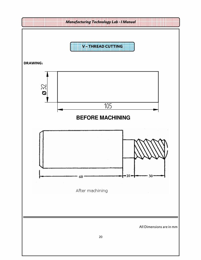
20
DRAWING:
105
32
BEFORE MACHINING
Ø
All Dimensions are in mm
Manufacturing Technology Lab - I Manual
V – THREAD CUTTING

21
Ex. No: Date: AIM:
To obtain the required shape and size of the work piece by turning and thread cutting.
MATERIALS SUPPLIED:
Cylindrical work piece of diameter 32 mm and length 105 mm mild steel rod.
TOOLS REQUIRED:
1. Lathe
2. Cutting tool
3. Vernier caliper
4. Try square
5. Scriber
6. Vernier height gauge
SEQUENCE OF OPERATIONS:
1. Checking
2. Work piece setting
3. Tool setting
4. Facing
5. Turning
6. Chamfering
7. Thread cutting.
Manufacturing Technology Lab - I Manual
3. SINGLE & V-START MULTI THREAD CUTTING

22
DRAWING:
All Dimensions are in mm
Manufacturing Technology Lab - I Manual

23
WORKING STEPS:
1. The given work piece is checked for its dimension.
2. The work piece is held in the chuck. Chuck key is used to tighten the job firmly, ensuring
centering of work piece.
3. The single point cutting tool is held in the tool post and tightens the nuts using spanner.
4. Facing is done with cutting tool moving from the centre of work piece towards outside. It is
one until the required length of the job is obtained.
5. Turning is done to reduce the diameter of the job. Sufficient depth of cit is given and it is
done until the required diameter of the job is obtained.
6. For chamfering to be done at the end of the work piece, the tool is held at 450 to the lathe
axis and is fed against the rotating work spice.
7. The cutting tool in the tool post is taken out. Thread cutting tool is held in the tool post and
tightened the nuts.
8. For right hand thread the lead screw rotates in clock wise direction and for left thread, it
rotates in anti clock wise direction. The carriage is engaged to lead screw and automatic
feed is given.
9. Suitable depth is given and thread is cut on the work spice.
10. Finally the dimension of work piece and pitch of the thread are again checked.
RESULT:
Thus the required size and shape of the given work piece is obtained.
Manufacturing Technology Lab - I Manual
Department of Mechanical Engineering Assessment of Practical
Description Maximum Marks Marks Obtained
Performance 25
Record 15
Viva – Voce 10
Total 50
24
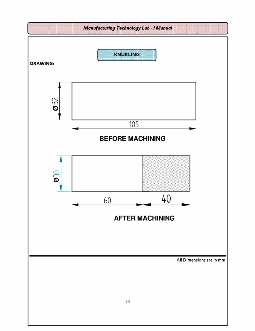
DRAWING:
105
32
BEFORE MACHINING
Ø
AFTER MACHINING
60 40
30Ø
All Dimensions are in mm
Manufacturing Technology Lab - I Manual
KNURLING

25
Ex. No: Date: AIM:
To obtain the required shape and size of the work piece by Facing, plain turning and knurling.
MATERIALS SUPPLIED:
Cylindrical work piece of diameter 32 mm and length 105 mm mild steel rod.
TOOLS REQUIRED:
1. Lathe
2. Cutting tool
3. Vernier caliper
4. Try square
5. Scriber
6. Vernier height gauge
7. Knurling tool
SEQUENCE OF OPERATIONS:
1. Checking
2. Work piece setting
3. Tool setting
4. Facing
5. Turning
6. Knurling
Manufacturing Technology Lab - I Manual
4. KNURLING

26
DRAWING:
All Dimensions are in mm
Manufacturing Technology Lab - I Manual

27
WORKING STEPS:
1. The given work piece is checked for its dimension.
2. The work piece is held in the chuck. Chuck key is used to tighten the job firmly, ensuring
centering of work piece.
3. The single point cutting tool is held in the tool post and tightens the nuts using spanner.
4. Facing is done with cutting tool moving from the centre of work piece towards outside. It is
one until the required length of the job is obtained.
5. Turning is done to reduce the diameter of the job. Sufficient depth of cit is given and it is
done until the required diameter of the job is obtained.
6. Fix the knurling tool in the tool post.
7. Move the carriage outward, and then move it longitudinally, and give a small cross feed.
Repeat this step until knurling of required length is done.
8. Finally the dimension of work piece is again checked.
RESULT:
Thus the required size and shape of the given work piece is obtained.
Manufacturing Technology Lab - I Manual

28
DRAWING:
105
32
BEFORE MACHINING
Ø
AFTER MACHINING
100
25
30 20
Ø Ø
All Dimensions are in mm
BORING AND INTERNAL THREAD CUTTING
Manufacturing Technology Lab - I Manual

29
Ex. No: Date:
AIM:
To obtain the required shape and size of the work piece by Facing, plain turning and Boring
and internal threading.
MATERIALS SUPPLIED:
Cylindrical work piece of diameter 32 mm and length 105 mm mild steel rod.
TOOLS REQUIRED:
1. Lathe
2. Cutting tool
3. Vernier caliper
4. Try square
5. Scriber
6. Vernier height gauge
7. Boring tool and internal thread cutting tool.
SEQUENCE OF OPERATIONS:
1. Checking
2. Work piece setting
3. Tool setting
4. Facing
5. Turning
6. Boring
7. Thread cutting.
Manufacturing Technology Lab - I Manual
5. BORING AND INTERNAL THREAD CUTTING

30
DRAWING:
All Dimensions are in mm
Manufacturing Technology Lab - I Manual

31
WORKING STEPS:
1. The given work piece is checked for its dimension.
2. The work piece is held in the chuck. Chuck key is used to tighten the job firmly, ensuring
centering of work piece.
3. The single point cutting tool is held in the tool post and tightens the nuts using spanner.
4. Facing is done with cutting tool moving from the centre of work piece towards outside. It is
one until the required length of the job is obtained.
5. Turning is done to reduce the diameter of the job. Sufficient depth of cit is given and it is
done until the required diameter of the job is obtained.
6. Fix the boring tool in the tail stock.
7. Slowly given the feed by rotating the wheel in the tailstock which moves the tool
longitudinally to producing a boring.
8. Fix the internal threading tool, to cut the internal thread.
9. Finally the dimension of work piece is again checked.
RESULT:
Thus the required size and shape of the given work piece is obtained.
Manufacturing Technology Lab - I Manual
Department of Mechanical Engineering Assessment of Practical
Description Maximum Marks Marks Obtained
Performance 25
Record 15
Viva – Voce 10
Total 50

32

33
UNIT – II WELDING

34
INTRODUCTION
Welding is the metal joining method wherein localized coalescence is produced either by
heating the metal to suitable temperatures, with or without use of filler metal or by application of
pressure.
The filler material has similar composition and melting point temperatures as the base metal. It
is used to fill gap between the joint surfaces.
TYPES OF WELDING
1. PLASTIC WELDING:
The pieces of metal to be joined are heated to the plastic state and then forced together by external
pressure without the filler material.
a. FORGE WELDING:
The work pieces are placed in a forge or other appropriate furnace and heated within the area to be
joined to the plastic condition. Then parts are quickly superimposed and worked into a complete union
by hand or power hammering or by pressing together.
b. RESISTNACE WELDING:
In resistance welding, a heavy electric current is passed through the metals to be joined over limited
area, causing them to be locally heated to plastic state and the welding is completed by the application
of pressure for the prescribed period of time.
c. THERMIT WELDING:
It is a fusion process in which weld is effected by pouring super heated liquid Thermit Steel, around the
parts to be united with or without the pressure.
Manufacturing Technology Lab - I Manual

35
2. FUSION WELDING:
a. GAS WELDING:
Gas welding is a process in which the required heat to melt the surfaces is supplied by a high
temperature flame obtained by a mixture of two gases. Usually the mixture of oxygen and acetylene is
used for welding purpose.
b. OXY-ACETYLENE WELDING:
In oxy-acetylene welding Oxygen and Acetylene are the two gases used for producing flame. The
Oxygen is manly used for supporting the combustion intensity.
TYPES OF FLAMES:
1. Neutral Flame (Oxygen, Acetylene in equal proportions)
2. Oxidizing Flame (excess of Oxygen)
3. Reducing Flame (excess of Acetylene)
Manufacturing Technology Lab - I Manual

36
WELDING TECHNIQUES:
There are two techniques in gas welding, depending upon the ways in which the welding rod and the
welding torch are used.
(i) Leftward technique or Forehand welding method
(ii) Rightward technique or Backhand welding method.
(I) LEFTWARD TECHNIQUE:
1. The welder holds welding torch in his right hand and filler rod in the left hand.
2. The welding flame is directed away form the finished weld.
ADVANTAGES:
1. The flame is pointed in the direction of welding; it preheats the edges of joint.
2. Good control and neat appearance arc characteristics are ensured in the leftward technique.
(II) RIGHTWARD TECHNIQUE:
1. Here the welding torch is held in the right hand of the welder and the filler rod in the left.
2. The welding flame is directed towards the finished weld (i.e. opposite to that when employing
the leftward technique)
ADVANTAGES:
1. As the flame is always directed towards the solidified weld, it results in annealing effect and
better mechanical properties are obtained.
2. Very little agitation is produced because torch moves in a straight line.
Manufacturing Technology Lab - I Manual

37
FILLER METAL:
It is the material that is added to the weld pool to assist in filling the gap. Filler metal forms an integral
part of the weld. The filler metal is usually available in rod form. These rods are called filler rods.
FLUXES:
During the welding, if the metal is heated in air, oxygen in the air combines with the metal to form
oxides which result in poor quality, low strength welds or in some cases may even make welding
impossible. In order to avoid these problems, a flux is added during the welding. This flux prevents
oxidation by preventing oxygen from contacting the weld zone.
No flux is used in the gas welding of steel. The most commonly used flux materials are Boric acid, soda
ash and sodium chloride.
ADVANTAGES OF GAS WELDING:
1. It can be applied to a wide variety of manufacturing and maintenance situations.
2. The rate of heating and cooling is relatively slow.
3. Since the sources of heat and of filler metal are separate, the welder has control over
filler-metal deposition rates.
DISADVANTAGES OF GAS WELDING:
1. Heavy sections cannot be joined economically.
2. Flame temperature is less than the temperature of the arc welding.
3. Fluxes used in certain welding and brazing operations produce fumes that are irritating to the
eyes, nose, throat and lungs.
Manufacturing Technology Lab - I Manual

38
ARC WELDING:
In arc welding process, the source of heat is electricity. In arc welding process, coalescence is produced
by heating the work piece with an electric arc struck between an electrode and the work piece.
Welding may be carried out in air or in an inert atmosphere. Filler material may or may not be used.
The temperature of the arc is of the order of 36000C.
PRINCIPLE OF ARC WELDING:
The heat required for joining the metals is obtained from an electric arc. The electric motor generator
or transformer sets are used to supply high electric current and the electrodes are used to produce the
necessary arc. The electrode serves as the filler rod and arc metals the surfaces so that the metals to be
joined are fused together.
The transformer type welding machine produces AC current. It takes power directly from power
supply and to produce high current and low voltage to the welding. It is least expensive.
Manufacturing Technology Lab - I Manual

39
Motor generator type welding machine produces DC current to welding machine. This current is
having straight or reversed polarity. The polarity selected for welding depends on the electrode arc
used in the welding.
WELDING BEAD CLEANING ACCESSORIES:
1. Chipping Hammer
2. Wire Brush
3. Hand Screen
4. Helmet
5. Tongs
6. Goggles
7. Hand Gloves
Manufacturing Technology Lab - I Manual

40
ADVANTAGES OF ARC WELDING:
1. Flux shielded manual metal arc welding is the simplest of all the arc welding processes.
2. The equipment can be portable and the cost is fairly low.
3. This process finds innumerable applications, because of the availability of a wide variety of
electrodes.
4. A big range of metals and their alloys can be welded.
DISADVANTAGES OF ARC WELDING:
1. Because of the limited length of each electrode and brittle flux coating on it, mechanization is
difficult.
2. In welding long joints (in pressure vessels), as one electrode finishes, the weld is to be
progressed with the next electrode. Unless properly cared, a defect (like slag inclusion or
insufficient penetration) may occur at the place where welding is restarted with the new
electrode.
APPLICATIONS OF ARC WELDING:
1. Today, almost all the commonly employed metals and their alloys can be welded by the arc
welding process.
2. Shielded metal arc welding is used both as a fabrication process and for maintenance and repair
jobs.
3. The process finds application in air receiver, tank, boiler and pressure vessel fabrication and
ship building.
4. Arc welding is used in building and bridge constructi
Manufacturing Technology Lab - I Manual

41
� LAP JOINT
� T- FILLET JOINT
� GAS CUTTING AND GAS WELDING
� BRAZING
WELDING EXERCISES
Manufacturing Technology Lab - I Manual
42
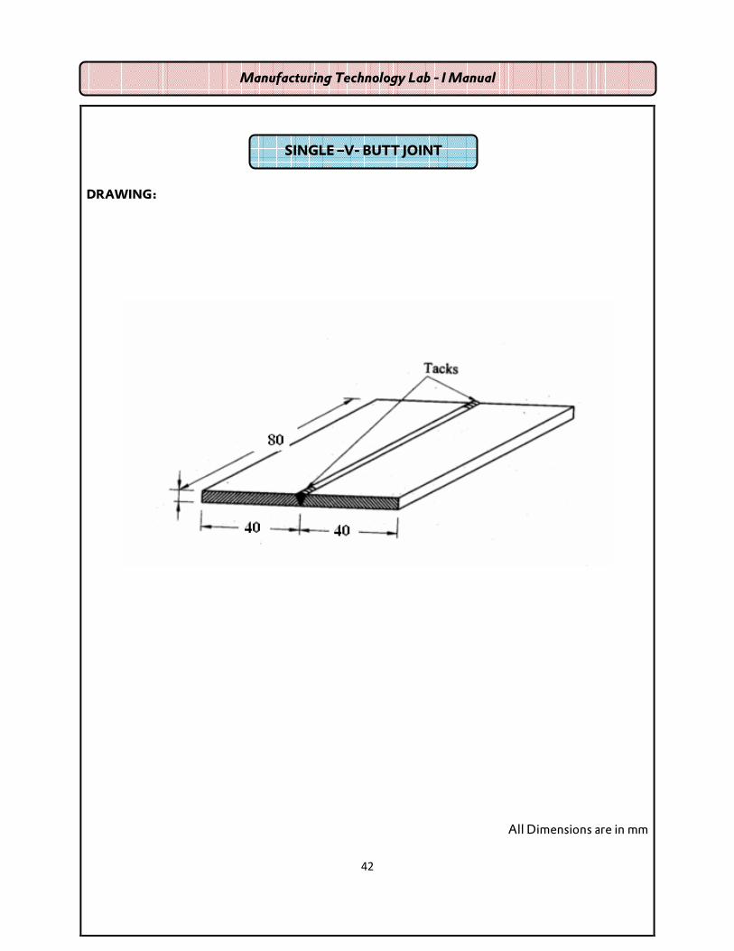
DRAWING:
All Dimensions are in mm
Manufacturing Technology Lab - I Manual
SINGLE –V- BUTT JOINT

43
Ex. No: Date: Aim:
To make a butt joint using arc welding on the given work pieces.
MATERIAL SUPPLIED:
Mild Steel Plate of size 80 X 40 X 3 mm – 2 Nos.
TOOLS REQUIRED:
1. Power Supply (AC or DC)
2. Electrodes
3. Tongs
4. Chipping Hammer
5. Wire Brush
6. Gloves
7. Apron
8. Shield
9. Safety goggles
10. Earthling clamps
SEQUENCE OF OPERATIONS:
1. Edge preparation (Removal of rust, scale etc)
2. Tacking
3. Welding
4. Cooling
5. Chipping
6. Cleaning
1. HORIZONTAL WELDING (BUTT JOINT)
Manufacturing Technology Lab - I Manual

44
DRAWING:
All dimensions are in mm
Manufacturing Technology Lab - I Manual

45
WORKING STEPS:
1. First of all, the work pieces must be thoroughly cleaned of rust, scale and other foreign
material.
2. Then the given work pieces are placed on the table in such a way that two work pieces are
brought close to each other with some gap as shown in fig.
3. Connect the positive electric supply to electrode and negative electric supply to work.
(Since the given material is thin)
4. Now the welding current output may be adjusted.
5. When current is passed, arc is produced between the electrode and work pieces.
6. Set the two work pieces in correct position like butt joint and tack at both ends of the work
pieces.
7. Then the welding is carried out throughout the length.
8. As soon as the welding process is finished, switch off the current supply and drop the work
piece into water for cooling using tongs.
9. Slags are removed by chipping process with the help of chipping hammer.
10. Finally using wire brush welded portions are cleane
RESULT:
Thus the desired butt joint is obtained using arc welding.
Manufacturing Technology Lab - I Manual
Department of Mechanical Engineering Assessment of Practical
Description Maximum Marks Marks Obtained
Performance 25
Record 15
Viva – Voce 10
Total 50

46
DRAWING:
All Dimensions are in mm
Manufacturing Technology Lab - I Manual
LAP JOINT
47
Ex. No: Date: AIM:
To make a lap joint using arc welding on the given work pieces.
MATERIAL SUPPLIED:
Mild Steel Plate of size 80 X 40 X 3 mm – 2 Nos.
TOOLS REQUIRED:
1. Power Supply (AC or DC)
2. Electrodes
3. Tongs
4. Chipping Hammer
5. Wire Brush
6. Gloves
7. Apron
8. Shield
9. Safety goggles
10. Earthing clamps
SEQUENCE OF OPERATIONS:
1. Edge preparation (Removal of rust, scale etc)
2. Tacking
3. Welding
4. Cooling
5. Chipping
6. Cleaning
Manufacturing Technology Lab - I Manual
2. OVER LAPING WELDING (LAP JOINT)

48
DRAWING
All Dimensions are in mm
Manufacturing Technology Lab - I Manual

49
WORKING STEPS:
1. First of all, the work pieces must be thoroughly cleaned to remove rust, scale and other
foreign material.
2. Now the work pieces are placed on the table in such a way that two work pieces are
overlapped one over another as shown in fig.
3. Connect the positive electric supply to electrode and negative electric supply to work.
(Since the given material is thin)
4. Now the welding current output may be adjusted.
5. When current is passed, arc is produced between the electrode and work pieces.
6. Set the two work pieces in correct position like lap joint and tack at both ends of the work
pieces as shown in fig.
7. Then the welding is carried out throughout the length of the work piece.
8. As soon as the welding process is finished, switch off the current supply
9. Then drop the work piece into water for cooling, after that slags are removed by chipping
process with the help of chipping hammer.
10. Finally by using wire brush, welded portions (weldment) are cleaned.
RESULT:
Thus the desired lap joint is obtained using arc welding.
Manufacturing Technology Lab - I Manual
Department of Mechanical Engineering Assessment of Practical
Description Maximum Marks Marks Obtained
Performance 25
Record 15
Viva – Voce 10
Total 50

50
DRAWING:
All Dimensions are in mm
Manufacturing Technology Lab - I Manual
T – FILLET JOINT

51
Ex. No: Date:
AIM:
To make a T-Fillet joint using arc welding on the given work pieces.
MATERIAL SUPPLIED:
Mild Steel Plate of size 80 X 40 X 3 mm – 2 Nos.
TOOLS REQUIRED:
1. Power Supply (AC or DC)
2. Electrodes
3. Tongs
4. Chipping Hammer
5. Wire Brush
6. Gloves
7. Apron
8. Shield
9. Safety goggles
10. Earthing clamps
SEQUENCE OF OPERATIONS:
1. Edge preparation (Removal of rust, scale etc)
2. Tacking
3. Welding
4. Cooling
5. Chipping
6. Cleaning
3. VERTICAL WELDING T – FILLET JOINT
Manufacturing Technology Lab - I Manual

52
DRAWING:
All Dimensions are in mm
Manufacturing Technology Lab - I Manual

53
WORKING STEPS:
1. First of all, the work pieces must be thoroughly cleaned to remove rust, scale and other
foreign material.
2. Now the work pieces are placed on the table in such a way that two work pieces are
brought close to each other ‘T’ shape is formed as shown in fig.
3. Connect the positive electric supply to electrode and negative electric supply to work.
(Since the given material is thin)
4. Now the welding current output may be adjusted.
5. When current is passed, arc is produced between the electrode and work pieces.
6. Set the two work pieces in correct position like T-Fillet joint and tack at both ends of the
work pieces as shown in fig.
7. The joint is placed on a welding table in a flat position by keeping the tack side down.
8. Then the welding is carried out throughout the length of the work piece.
9. As soon as the welding process is finished, switch off the current supply
10. Then drop the work piece into water for cooling, after that slags are removed by chipping
process with the help of chipping hammer.
11. Finally by using wire brush, welded portions (weldment) are cleaned.
RESULT:
Thus the desired T-Fillet joint is obtained using arc welding.
Manufacturing Technology Lab - I Manual

54
DRAWING:
All Dimensions are in mm
Manufacturing Technology Lab - I Manual
GAS CUTTING AND GAS WELDING

55
Ex. No: Date: AIM:
To cut and joint given metal sheets in gas welding
MATERIAL SUPPLIED:
Mild Steel Plate of size 80 X 40 X 3 mm – 2 Nos.
TOOLS REQUIRED:
1. Oxygen and acetylene gas cylinders with pressure regulators and pressure gauges.
2. Gas welding torch
3. Filler rod
4. Safety gloves
5. Goggle
6. Chipping hammer
7. Wire brush
SEQUENCE OF OPERATIONS:
1. Edge preparation (Removal of rust, scale etc)
2. Tacking
3. Welding
4. Cooling
5. Chipping
6. Cleaning
Manufacturing Technology Lab - I Manual
4. GAS CUTTING AND GAS WELDING

56
DRAWING:
All Dimensions are in mm
Manufacturing Technology Lab - I Manual
57
WORKING STEPS:
1. The surface of the plate to be welded is cleaned for perfect joint and more strength.
2. The metal sheets to be welded are positioned properly.
3. Open the acetylene and oxygen cylinder valves slowly, then open the acetylene valves in
the torch. Keep the tip of the torch away from the body and light it using lighter.
4. Adjust the oxygen and acetylene valves in the torch slowly to get the required flame for
welding.
5. Maintain the gap 3 mm between to be welded and inner cone of the flame.
6. The welding torch and filler rod are moved backwards along line into be welded.
7. Complete the welding process by removing slag using chipping hammer.
Result:
The two metal sheets are welded in gas welding.
Manufacturing Technology Lab - I Manual
Department of Mechanical Engineering Assessment of Practical
Description Maximum Marks Marks Obtained
Performance 25
Record 15
Viva – Voce 10
Total 50

58
BRAZING – INTRODUCTION- for demonstration purpose
Brazing is the process of joining metals with a nonferrous filter metal that has a melting point
below that of the metals being joined. By AWS definition, the melting point of the filler metal will be
above 8000F (4270C). Below this temperature are the solders. The filler metal must wet the surfaces to
be joined, that is, there must be a molecular attraction between the molten filler material and the
materials being joined. The brazing alloy, when heated to the proper temperature, flows into the small
joint clearances by capillary action. A limited amount of alloying occurs between the filler metal and
the base metal at elevated temperature. As a result, the strength of the joint when properly made may
exceed that of the base material. The strength is attributed to three sources, atomic forces between the
metals at the interface; alloying, which comes from diffusion of the metals at the interface; and inter
granular penetration.
The heat for brazing may be provided in many different ways, the most common o f which are by
torch, induction furnace, and hot dipping.
TYPES OF BRAZING:
1. TORCH BRAZING:
Torch brazing is one of the oldest and most widely used methods of heating for brazing; it is versatile
and adaptable to most jobs. It is especially good for repair work in the field and for small-lot jobs in the
shop. As it is a manual operation, torch brazing may have high labor costs, and the skill and judgment
of the torch operator will determine the quality of work. Torch brazing may be done with the use of
natural gas and oxygen, air and acetylene, butane, propane, MAPP, and the regular oxyacetylene.
2. INDUCTION BRAZING:
The heat of induction brazing is furnished by an AC coil placed in close proximity to the joint. The
high-frequency current is usually provided by a solid-state oscillator that produces a frequency of 200,
000 to 5, 000, 000 Hz. These alternating high-frequency currents induce opposing currents in the
work, which, by electrical resistance, develop the heat. This method has the advantage of
Manufacturing Technology Lab - I Manual

59
providing good heat distribution, accurate heat control, uniformity of results, and speed. It is
especially good for certain types of repetitive work that require close control.
3. FURNACE BRAZING:
Parts are to be furnace brazed have the flux and brazing material pre placed in the joint. If the furnace
has a neutral or shielding atmosphere, the flux may not be necessary. The furnace may be batch or
conveyor type. Automatic controls regulate both time and temperature and, where applicable,
atmosphere. The three steps used in copper-hydrogen furnace brazing are shown in figure.
Manufacturing Technology Lab - I Manual

60
4. DIP BRAZING:
Dip brazing gets its name from the fact that parts are jigged (or in some cases the parts are self-
jiggning, as shown in fig) and are placed in a chemical or molten-metal bath maintained at the correct
brazing temperature. In a chemical bath, the parts are first thoroughly cleaned and then assembled
with a filler-metal placed on or in the joint. The bath, usually molten salts, is maintained at a higher
temperature than the filler metal being used. After dipping, the parts are removed and immediately
cleaned to remove the flux. The number and size of the parts to be brazed limited only by the capacity
of the bath and the handling facilities.
5. PASTE BRAZING:
A newer development in brazing is paste brazing. Anyone who has done any brazing knows there is
some skill involved. After the appropriate type and amount of flux and filler metal are selected, the
appropriate temperature must be chosen. Too little flux means the base metal will not be sufficiently
cleaned, resulting in a weak joint. To ensure strong joints, excessive flux is often used, this wastes
material, requires more cleaning, and can erode parts and fixtures.
Manufacturing Technology Lab - I Manual

61
6. PASTE ALLOY PROCESS:
Paste alloys are designed to overcome the problems given in the previous paragraph. Paste alloys are
blends of filler metal in powdered form and a flux that are held in suspension by a paste-type binder.
Premixing of flux and filler ensures the proper proportions of each and keeps the alloy localized to the
joint area. Pastes rely on capillary action to spread the metal and flux over the joint area. Paste brazing
filler materials are available in silver, nickel, copper and gold based formulations.
7. BRAZE WELDING:
Braze welding is similar to brazing in that the base metal is not melted but joined by an alloy of lower
melting point. The main difference is that in braze welding the alloy is not drawn into the joint by
capillary action. A braze-welded joint is prepared very much lik a joint is prepared for welding except
that an effort should be made to avoid sharp corners, because they are easily overheated and may also
be points of stress concentration.
BRAZING FLUXES:
Generally, fluxes are available in 3 forms namely powder, paste or liquid. Of the three, paste is most
commonly used, although powdered flux is frequently mixed with water or alcohol to give a paste like
consistency.
BRAZING FILLER METALS:
Brazing filler metals are divided into seven classifications. In order of popularity, these are silver,
copper, copper-zinc, copper-phosphorus, aluminium-silicon, copper-gold, and magnesium. These
alloys are produced in many forms such as wire, rods, coated sheets, and powder. Frequently, brazing
alloys are performed into rings or special shapes to simplify placement of the correct amount at the
joint.
ADVANTAGES OF BRAZING:
Brazing is well suited to mass-production techniques for joining both ferrous and non-ferrous
metals. Some of the principal advantages are
1. Dissimilar metals can be joined easily.
2. Assembles can be joined in a virtually stree-free condition.
3. Complex assemblies can be joined in several steps by using filler metals with progressively
lower melting temperatures.
4. Materials of different thickness can be joined easily.
Manufacturing Technology Lab - I Manual

62
5. Brazed joints require little or no finishing other than flux removal.
LIMITATIONS OF BRAZING:
1. Joint design is somewhat limited if strength is a factor.
2. Joining is generally limited to sheet-metal thicknesses and relatively small assembles.
3. Cost of joint preparation can be high.
Manufacturing Technology Lab - I Manual

63
UNIT – III SHEET METAL

64
INTRODUCTION
Sheet metal work is working on the metal of 16 gauges to 30 gauges, with hand tools and
simple machines into different forms by cutting, forming into shape and joining.
Sheet metal work is one of the major applications in engineering industry. It has its own
significance as a useful trade in engineering work.
APPLICATION OF SHEET METAL
Sheet metal work is used for making
Hoppers
Funnels
Various ducts
Chimneys
Ventilating pipes
Machine tool guards
Boiler etc.
PROCEDURE FOR SHEET METAL WORK
The exact size and shape of the sheet to be cut is given by the development of the concerned
object.
The development is drawn on a flat sheet of metal and then the sheet is cut.
The cut sheet is folded or rolled to the required shape before the joints are made by welding or
any form of fastening.
METAL USED IN SHEET METAL WORK
a. Black iron
b. Galvanized iron
c. Stainless steel
d. Copper
e. Aluminum
Manufacturing Technology Lab - I Manual

65
f. Tin plate
g. Lead etc.
Selection of these metals is based upon the type of process.
TOOLS USED IN SHEET METAL
1. CUTTING TOOLS(CHISELS, SNIPS OR SHEARS)
(a) CHISELS: Chisels are used in sheet metal work for cutting sheets, rivets, bolts, and
chipping operations. Though there are many types of chisels available, round nose chisel
and flat chisel are mostly used for sheet metal work.
(b) SNIPS (OR) SHEARS: Snips are hand shears, varying in length from 200mm to 600mm.
and 250mm length is most commonly used.
STRAIGHT SNIPS are used for cutting along outside curves and Straight lines.
CURVED SNIPS OR BENT SNIPS are used for trimming along inside curves.
2. STRIKING TOOLS
(a) Hammers (b) Punches
Manufacturing Technology Lab - I Manual

66
(a) Hammers: Hammers are used in sheet metal work for following, raising, Stretching or
throwing off. The following hammers are mostly used in sheet metal work.
(i) Riveting hammers
(ii) Raising hammers
(iii) Setting hammers
(b) Punches: In sheet metal work, punch is used for marking out work locating centers etc.
The following two types of punches are widely used.
(i) Prick punch
(ii) Centre punch.
3. SUPPORTING TOOLS
Stacks: Stacks are nothing but sheet metal workers anvils used for bending, seaming or
forming, using a hammer or mallet. The following fig. shows different shapes and sizes of
stakes.
4. BENDING TOOLSPliers: Pliers are mainly used for bending the sheet metal to the required
shape. It is also used for holding and cutting the sheet metal. Flat nose pliers and round nose
pliers are used in sheet metal work for forming and holding.
Manufacturing Technology Lab - I Manual

67
5. LAYOUT TOOLS.
Steel rule: It is used for measuring and laying out small work. It can measure with an
Accuracy of up to 0.5mm.
Scriber: It is a long wire of steel with its one end sharply pointed and hardened to scrach line
on sheet metal in laying out patterns.
Dividers: Dividers are used for drawing circles or arcs on sheet metal. They are to mark a
desired distance between points and to divide lines into parts
Trammels: It is used for making of arcs and circles. Maximum size of the arc that can be scribed
depends on the length of the beam in scriber.
SHEET METAL OPERATIONS
1. Shearing
2. Bending
3. Drawing
4. Squeezing.
Manufacturing Technology Lab - I Manual

68

69
� SQUARE TRAY
� FUNNEL
SHEET METAL EXERCISES

70
DRAWING:
150
100
5
5
All Dimensions are in mm
Manufacturing Technology Lab - I Manual
SQUARE TRAY

71
Ex. No: DATE: AIM: To make a tray from given sheet metal.
MATERIL SUPPLIED:
22 gauge Galvanized Iron (GI) sheet.
TOOLS REQUIRED:
1. Snips
2. 2. Ball peen hammer
3. Mallet
4. Steel rule
5. Scriber
6. Divider
7. Rivet set
8. Dot punch
9. Stakes
SEQUENCE OF OPERATIONS:
1. Checking
2. Leveling
3. Marking
4. Cutting
5. Hemming
6. Bending
7. Riveting
Manufacturing Technology Lab - I Manual
1. FABRICATION OF SHEET METAL TRAY

72
DRAWING:
All Dimensions are in mm
Manufacturing Technology Lab - I Manual

73
WORKING STEPS:
1. The size of the given sheet is checked using a steel rule.
2. Then the sheet is leveled on the leveling plate using a mallet.
3. The dimensions are marked as shown in fig
4. The sheet is cut as per the marked dimensions by straight snips.
5. Then a single hemming is made on the four sides of tray as shown in fig.
6. These four sides of the tray are bent to 90 0 using stakes anvil.
7. Finally the corners of the tray are joined by riveting.
RESULT:
Thus the tray is made from the given metal sheet.
Manufacturing Technology Lab - I Manual
Department of Mechanical Engineering Assessment of Practical
Description Maximum Marks Marks Obtained
Performance 25
Record 15
Viva – Voce 10
Total 50

74
23,09
PART - 1
PA
RT
- 2
49,28
50
80
L
L1
P
Q
O
Ø
All Dimensions are in mm
FUNNEL
Manufacturing Technology Lab - I Manual

75
Ex. No: DATE:
AIM:
To make a funnel from given sheet metal.
MATERIL SUPPLIED:
22 gauge Galvanized iron (GI) sheet.
TOOLS REQUIRED:
1. Snips
2. Ball peen hammer
3. Steel rule
4. Scriber
5. Divider
6. White paper
7. Protractor
8. Stakes
SEQUENCE OF OPERATIONS:
1. Checking
2. Marking on paper
3. Marking on sheet metal
4. Cutting
5. Folding.
6. Hemming
7. Soldering.
FABRICATION OF FUNNEL
Manufacturing Technology Lab - I Manual

76
DRAWING:
All Dimensions are in mm
Manufacturing Technology Lab - I Manual

77
WORKING STEPS:
1. The size of the given sheet metal is checked for its dimensions using steel rule.
2. The required developed of surface is being made on the white paper which is overlapped
on the sheet metal.
3. The marking is done on the sheet metal as per the development being done on the paper.
4. Now using straight snips, unwanted materials are removed.
5. Now fold and bend the work piece to make the funnel shape and joint is made on the work
piece.
6. Then using groove, locked grooved joint is made for about 5mm. Also, hemming is done in
the bottom of the funnel.
7. In between top face and bottom face, butt joint is made using solder.
8. Finally, trimming and finishing operation are being carried out.
RESULT:
The funnel of the required dimensions is made from the given metal sheet.
Manufacturing Technology Lab - I Manual
Department of Mechanical Engineering Assessment of Practical
Description Maximum Marks Marks Obtained
Performance 25
Record 15
Viva – Voce 10
Total 50

78
79
UNIT – IV PREPARATION OF
SAND MOULD

80
INTRODUCTION
Producing Components by casting has been used since the earliest days of civilization. Lot of shapes
and sizes can be prepared in a casting process. To make the casting of a component, a cavity of desired
shape is t be produced in which the molten metal is poured.
Mould is the cavity to the required shape made in modeling sand or other material. The process of
modeling consists of all operations done to make a mould.
PATTERN:
Pattern is the model used to get required casting. It is used to produce the moduld cavity in
sand.
FOUNDRY:
The place where modeling and casting are done is known as foundry.
MOULDING SAND OR GREEN SAND:
It is a maximum of sand and additives such as water, bentonite, inoculent, sodium silicate etc,
used to create mould cavity.
COMPONENTS REQUIRED FOR MOULDING:
The following components are essential for producing mould.
(i) Moulding Sand(Green sand)
(ii) Moulding Boxes
(iii) Pattern
(iv) Moulding tools
MOULDING SAND
Composition
It is a special type of sand used for making mould. Moulding sand has three
constituents. They are
(i) Sand (ii) Binder (iii) Additive
Manufacturing Technology Lab - I Manual

81
SAND:
It has silica, clay and moisture. Silica is the main constituent of sand. Silica has 80 to 90 %
silicon dioxide. Silicon gives refractoriness to the sand.
CLAY:
Clay is another constituent of sand. Clay gives more bonding strength to the sand. Generally
sand has 5 to 20 % clay. Moisture is the water added to the sand. It gives the bonding action. In general
2 to 8 % water is added to the sand.
BINDERS:
Binders are added to the moulding sand to bring the property of the cohesiveness. The binder
binds the sand grains together and brings strength. There are three types of binders.
a) Clay type binders eg: Bentonite
b) Organic binders eg.Resin
c) Inorganic binders eg. Sodium silicate.
ADDITIVE:
By adding an additive, properties like strength, refractoriness and permeability can be
increased.
PATTERNS:
A pattern is the replica of the desired casting, used to produce a mould into which liquid metal
is poured. When pattern packed in a suitable material produces a cavity called mould. This cavity when
filled molten metal produces the desired casting,
The following pattern materials are widely used.
i) Wood and wood products
ii) Metals and alloys
iii) Plastic and rubbers
iv) Plasters and Waxes
Manufacturing Technology Lab - I Manual
82
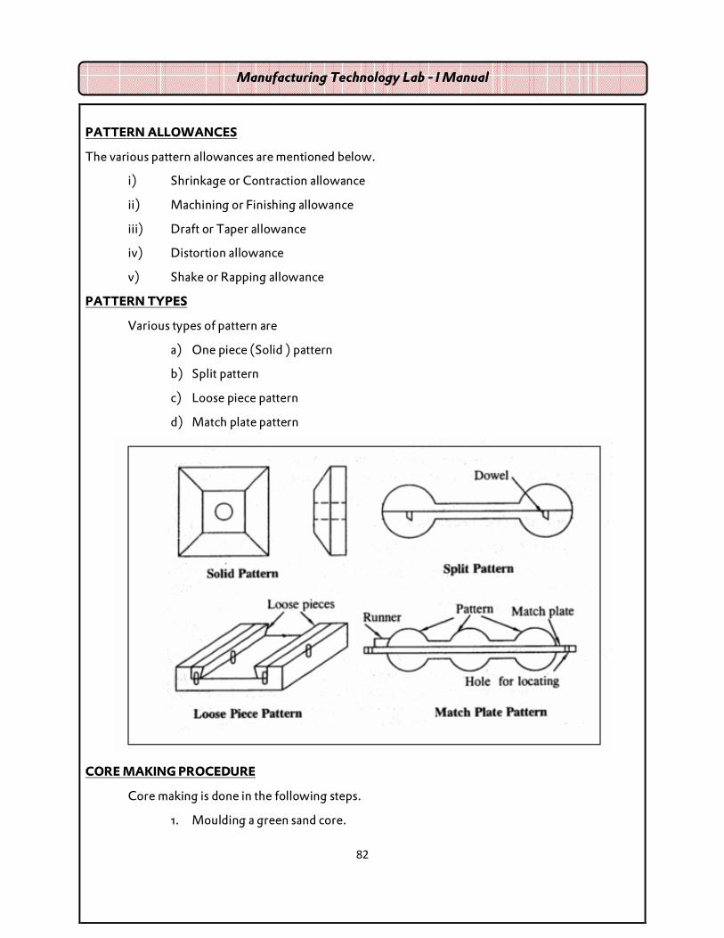
PATTERN ALLOWANCES
The various pattern allowances are mentioned below.
i) Shrinkage or Contraction allowance
ii) Machining or Finishing allowance
iii) Draft or Taper allowance
iv) Distortion allowance
v) Shake or Rapping allowance
PATTERN TYPES
Various types of pattern are
a) One piece (Solid ) pattern
b) Split pattern
c) Loose piece pattern
d) Match plate pattern
CORE MAKING PROCEDURE
Core making is done in the following steps.
1. Moulding a green sand core.
Manufacturing Technology Lab - I Manual

83
2. Baking
3. Finishing
4. Coating
MOULDING BOXES
1. Cope (Top box)
2. Check (middle box)
3. Drag (bottom box)
MOULDING TOOLS:
1. Shovel
2. Sieve
3. Trowel
4. Rammers
5. Sprue pin
6. Strike off bar
7. Lifter
8. Gate cutter
9. Runner
10. Riser
11. Vent rod
12. Draw spike
13. Bellow
ADVANTAGES OF SAND CASTING:
1. Use is widespread; technology well developed
Manufacturing Technology Lab - I Manual

84
2. Materials are inexpensive, capable of holding detail and resist deformation when
heated.
3. Process is suitable for ferrous and non-ferrous metal casting.
4. Handles a more diverse range of products than any other casting method.
5. High levels of sand reuse are achievable.
LIMITATIONS OF SAND CASTING
1. Typically limited to one or more a small number moduls per box.
2. Sand: metal ratio is relatively high.
3. High level of waste is typically generated, particularly sand, bag house dust and
spent shot.
Manufacturing Technology Lab - I Manual

85
MOULDING TOOLS
Manufacturing Technology Lab - I Manual

86

87
� SOLID PATTERNS
� MOULD WITH SPLIT PATTERN
� MOULD WITH LOOSE – PIECE PATTERNS
� INJECTION MOULDING
FOUNDRY EXERCISES

88
DRAWING:
All Dimensions are in mm
SOLID PATTERN
Manufacturing Technology Lab - I Manual

89
Ex. No: Date: AIM: To make the mould of solid pattern
MATERIAL REQUIRED:
Molding sand, Parting sand, facing sand, pattern, molding boxes etc.
TOOLS REQUIRED:
1. Shovel
2. Sieve
3. Trowel
4. Rammers
5. Sprue pin
6. Strike off bar
7. Lifter
8. Gate cutter
9. Runner
10. Riser
11. Vent rod
12. Draw spike
13. Bellow
SEQUENCE OF OPERATIONS:
1. Sand preparation
2. Core preparation
3. Placing the pattern on the moulding board.
Manufacturing Technology Lab - I Manual
1. MOULD WITH SOLID PATTERN
90
DRAWING:
Dimensions are in mm
Manufacturing Technology Lab - I Manual

91
4. Ramming of drag
5. Placing runner and riser
6. Ramming of cope
7. Removal of pattern, runner, riser
8. Gate cutting.
WORKING STEPS:
1. The pattern is placed on the moulding board.
2. A suitable core is prepared and placed in the hole of the pattern.
3. Clay washing is done inside the drag surface.
4. Parting sand is applied over the pattern.
5. Box is filled with smooth moulding sand and proper ramming is done using flat and
peen rammer.
6. Excess sand is removed using the strike off bar.
7. The drag is turned upside down.
8. The cope is placed on the drag after doing clay wash.
9. The runner and riser are placed over the pattern.
10. After applying parting sand, moulding, sand is filled over the part ten.
11. Ramming is done to get a rigid mould.
12. Using strike off bar excess sand is removed.
13. Vent holes are made using vent rod.
14. Runner and riser are removed and a funnel shape is made on the runner hole.
15. Cope is kept aside and the pattern is removed using draw spike
16. The cope is placed on the drag.
RESULT:
Thus the gear mould is prepared and ready for casting.
Manufacturing Technology Lab - I Manual
Department of Mechanical Engineering
Assessment of Practical
Description Maximum Marks
Performance 25
Record 15
Viva – Voce 10
Total 50

92
DRAWING:
All Dimensions are in mm
Manufacturing Technology Lab - I Manual
MOULD WITH SPLIT PATTERN (V-GROOVED PULLEY)

93
Ex. No: Date:
AIM: To prepare a sand mould using a split pattern.
MATERIAL REQUIRED:
Moulding sand, Parting sand, facing sand, split pattern, Moulding boxes etc.
TOOLS REQUIRED:
1. Showel
2. Sieve
3. Trowel
4. Rammers
5. Sprue pin
6. Strike off bar
7. Lifter
8. Gate cutter
9. Runner
10. Riser
11. Vent rod
12. Draw spike
13. Bellow
SEQUENCE OF OPERATIONS:
1. Sand preparation
2. Core preparation
3. Placing the pattern on the moulding board
Manufacturing Technology Lab - I Manual
2. MOULD WITH SPLIT PATTERN (V-GROOVED PULLEY)

94
DRAWING:
All Dimensions are in mm
Manufacturing Technology Lab - I Manual

95
4. Ramming of drag
5. Placing runner and riser
6. Ramming of cope
7. Removal of pattern, runner, riser
8. Gate cutting.
WORKING STEPS:
1. The mould box, pattern, tools, and the table /floor are cleaned.
2. The drag is filled with green sand after positioning lower part of the pattern on the
table.
3. The green sand is rammed carefully and the excess sand is struck off.
4. Till the drag upside down and sprinkle river sand on top of it.
5. The cope is positioned on the top of the drag and upper part of the pattern is positioned
carefully.
6. Position the sprue pin and riser pin, then the fill cope with sand ramming is done and
the excess sand is struck off.
7. Remove the sprue pin and the riser pin carefully
8. Apply water on the edges of the pattern and remove them carefully using the draw
spike, then finish the cavity.
9. Vent holes are made using vent wire.
10. A funnel – shaped opening and gate is made to pour the molten metal.
RESULT:
Thus the mould cavity of the given split pattern is obtained.
Manufacturing Technology Lab - I Manual
Department of Mechanical Engineering Assessment of Practical
Description Maximum Marks Marks Obtained
Performance 25
Record 15
Viva – Voce 10
Total 50

96
DRAWING:
All Dimensions are in mm
Manufacturing Technology Lab - I Manual
MOULD WITH LOOSE-PIECE PATTERN

97
Ex. No: Date:
AIM:
To prepare a sand mould using a loose – piece pattern.
MATERIAL REQUIRED:
Moulding sand, Parting sand, facing sand, pattern, Molding boxes etc.
TOOLS REQUIRED:
1. Showel
2. Sieve
3. Trowel
4. Rammers
5. Sprue pin
6. Strike off bar
7. Lifter
8. Gate cutter
9. Runner
10. Riser
11. Vent rod
12. Draw spike
13. Bellow
SEQUENCE OF OPERATIONS:
1. Sand preparation
2. Core preparation
3. Placing the pattern on the moulding board
Manufacturing Technology Lab - I Manual
3. MOULD WITH MOULD WITH LOOSE-PIECE PATTERN

98
DRAWING:
All Dimensions are in mm
Manufacturing Technology Lab - I Manual

99
4. Ramming of drag
5. Placing runner and riser
6. Ramming of cope
7. Removal of pattern, runner, riser
8. Gate cutting.
WORKING STEPS:
1. The mould box, pattern, tools, and the table /floor are cleaned.
2. The drag is filled with green sand after positioning lower part of the pattern on the
table.
3. The green sand is rammed carefully and the excess sand is struck off.
4. Till the drag upside down and sprinkle river sand on top of it.
5. The cope is positioned on the top of the drag and upper part of the pattern is positioned
carefully.
6. Position the sprue pin and riser pin, then the fill cope with sand ramming is done and
the excess sand is struck off.
7. Remove the sprue pin and the riser pin carefully
8. Apply water on the edges of the pattern and remove them carefully using the draw
spike, then finish the cavity.
9. Vent holes are made using vent wire.
10. A funnel – shaped opening and gate is made to pour the molten metal.
RESULT:
Thus the mould cavity of the given loose piece pattern is obtained.
Manufacturing Technology Lab - I Manual
Department of Mechanical Engineering Assessment of Practical
Description Maximum Marks Marks Obtained
Performance 25
Record 15
Viva – Voce 10
Total 50

100

101
INJECTION MOULDING - INTRODUCTION- for demonstration purpose
WORKING PRINCIPLE:
The injection moulding is used to achieve high speed moulding of thermoplastics. The working
principle of this process is tat the molten thermoplastic is injected into a mould under high pressure.
For achieving high pressure, the plunger system is used.
OPERATION:
The moulding material is loaded into a hopper from which it is transferred to a heating section by a
feeding device where the temperature is raised to 1500 C - 3700 C. The material melts and is forced by
an injection ram or by plunger through a nozzle and sprue in a closed mould which forms the part.
There are two types of injection moulding and it is given below.
RAM OR PLUNGER TYPE INJECTION MOULDING:
The ram and plunger type injection moulding has two units.
1. Injection unit
2. Clamping unit.
So it may be split in order to eject the finished component.
Initially, the polymer is filled in a hopper. Then it goes to the heating section where the polymer is
melted and the pressure is increased. The heated material is injected by the ram under pressure. So, the
Manufacturing Technology Lab - I Manual

102
heated material is forced to fill in mould cavity through the nozzle to get the required shape of the
plastics. Here, the mould is water-cooled type.
SCREW TYPE INJECTION MOULDING:
In this type also, there are two units to split and eject the finished component such as
1. Injection unit
2. Clamping unit
The injection unit has hopper, screw and heating section. In clamping section, it has mould.
In screw type moulding machine, initially the pellets are fed into the hopper. The resins are pushed
along with the heated reciprocating screw. The screw is moved forward to force the plastic material
into the mould. The screw itself is moving backwards and allowing the accumulation of enough
material to fill the mould.
The rotation of the screw provides the plasticizing action by shearing and frictional effects. The axial
motion of the screw provides the filling action.
The jet moulding process is used to find the problems occurred in injection moulding process. The
reaction moulding is the recent development in injection moulding. In reaction moulding, the low
viscosity monomers are used in the mould. A chemical reaction takes place between resins at low
temperature and a polymer is created.
Manufacturing Technology Lab - I Manual

103
In jet moulding, the plastic is preheated about 930 C in the cylinder surrounding the nozzle. The
reaction moulding is suitable for the production of polyurethane moulding.
ADVANTAGES OF INJECTION MOULDING:
1. High production capacity and less material losses.
2. Low cost and less finishing operation.
3. It is used for making complex threads and thin walled parts.
4. Accuracy becomes ± 0.025 mm.
5. Wide range of shapes can be moulded.
APPLICATIONS:
1. It is used in making parts of complex threads.
2. Production of Intricate shapes like thin walled parts.
3. Production of typical parts like cups, containers, tool handles, toys, knobs, plumbing fittings.
4. Production of electrical and communication components like telephone receivers.
LIMITATIONS:
1. Equipment of cylinder and die should be non-corrosive.
2. Reliable temperature controls are essential.
The injection capacity of injection moulding machines ranges from 12,000 mm3 to2.2 X 106 mm3.
Manufacturing Technology Lab - I Manual