summit machine tool 26”, 30”, & 33” big hole engine lathe ... · 26”, 30”, &...
TRANSCRIPT

Summit Machine Tool 26”, 30”, & 33” Big Hole Engine Lathe Operation/Parts Manual
Summit Machine Tool Mfg. Corp. P.O. Box 1402 Oklahoma City, OK 73101 (405) 235-2075

- 2 -
SUMMIT MACHINE TOOL
MANUFACTURING CORP
BIG HOLE ENGINE LATHE
INSTRUCTION MANUAL &
PARTS LISTS
Model: 26 Series Spindle Bore: 6” & 9” 30 Series 33 Series

- 3 -
TABLE OF CONTENTS
Chapter Description Page 1 Operating Safety Guidelines 6 1.1 General Safety Precautions 6 1.2 Operating Hazards 7 1.3 Operating Safety Precautions and Personal Protective Equipment
(P.P.E.) 8
1.4 Safety Device Inspection 11 2 Overall Description of the Machine 12 2.1 Function, Intended Use, and Part Descriptions 12 2.2 Overall Dimension and Capacity Of Machine 13 2.3 Specifications 14 2.4 Standard and Optional Accessories 15 2.5 Operator Position and Noise Level 16 2.6 Spindle Bore and Tailstock Quill Taper Drawing 17 2.7 Quill Bore and Quill Taper Specifications 21 3 Preparations before Installing the Machine 22 3.1 Foundation Requirements 22 3.1.1 Dimensional Drawing 23 3.1.2 Foundation 24 3.2 Power Requirements 25 3.3 Site Location 25 4 Transportation and Installation 26 4.1 Transportation 26 4.1.2 Preparation and Safety Checks 26 4.1.3 Lifting Procedure 27 4.2 Installation 28 4.2.1 Cleaning 28 4.2.2 Level Adjustment 28 4.2.3 Power Source Wiring 29 4.2.4 Dismantling of the Machine 29 4.3 Chuck Mounting 30

- 4 -
TABLE OF CONTENTS
Chapter Description Page 5 Operation and Use 31 5.1 Spindle Speed Change 31 5.2 Description of Driving Unit 32 5.3 Feeds and Threads 34 5.4 Carriage and Apron 49 5.5 Chip Removing 40 5.6 Cross & Longitudinal Rapid Traverse 40 6 Maintenance 41 6.1 Lubrication 41 6.2 Coolant System 42 6.2.1 Coolant System Filling Procedure 43 6.2.2 Coolant System Cleaning Procedure 43 6.2.3 Coolant Capacities and Recommended Types for Ferrous Metal 43 6.3 Routine Maintenance Program 44 6.3.1 Weekly Check 44 6.3.2 Half Year Checks 44 6.3.3 Annual Checks 44 6.4 Trouble Shooting 45 7 Adjustment 46 7.1 Leveling Adjustment of Bed 46 7.2 Adjustment of Main Spindle Bearings 46 7.3 Adjustment Of Taper Gib 47 7.4 Eliminating Back-Lash of Cross Slide and Tool Post Slide 47 7.5 Adjustment of Carriage Gibs 47 7.6 Adjustment of Overload Protection Device 48 7.7 Adjustment of Half-Nut Supporter 48 7.8 Correcting Tailstock Alignment 49 Wiring Diagram 50
- 5 -
TABLE OF CONTENTS
Chapter Description Page 8 Electrical Circuit 51 8.1 Push Buttons on Headstock Control Panel 52 9 Diagrams and Part Lists 53 Headstock 54 Gear box 61 Apron & Threading Dials 68 Rapid Feed 74 Carriage, Tool Slide, & Taper Attachment 75 Tailstock 81 Bed and Leg 85 Micro Stopper 87 Turret Type 4-Step Stopper 88 Steady Rest 89 Follow Rest 91

- 6 -
CHAPTER 1: Operating Safety Guidelines
1.1 General Safety Precautions 1. The operator must be a trained technician.
2. The operator should wear safety glasses, safety shoes, etc, that conform to local
government industrial safety regulations.
3. Keep the machine and work area clean.
4. Keep all guards and cover plates in place and all machine cabinet doors closed.
5. Never lay anything on the working surfaces of the machine that may cause damage to rotating or moving parts.
6. Do not touch or reach over moving or rotating machine parts.
7. Ensure that you know how to stop the machine before starting it. Stop the machine
immediately if anything unexpected happens.
8. Check the load capacity of revolving centers for the current application.
9. Isolate the machine when leaving it unattended.
10. The use of fluid causing poisoning or corrosion while cutting is prohibited.
11. Do not operate the machine in excess of its rated capacity.
12. Do not wear rings, watches, ties, or loose sleeved clothing while operating the machine.
13. Do not interchange chucks or other spindle mounting items without checking for correct locking and maximum speed rating.
14. Do not cut magnesium metal, high magnesium alloys, or any other material which may
generate flame hazards.

- 7 -
1.2 Operating Hazards If the chuck type is incorrect, rotation of the spindle may result in extreme danger. If the gripping force required for any given application is unknown, then rotation of chuck will be hazardous. You must be careful when selecting a chuck.
It is possible for a work piece to become loose in the chuck due to the influence of centrifugal force under certain conditions. The factors involved include:
1. Spindle speed for a particular application is too high. 2. Weight and type of gripping jaws if the work piece is not standard. 3. The radius at which gripping jaws force is concentrated. 4. Chuck is inadequately lubricated. 5. The state of balance is not correct. 6. The gripping force applied to the work piece in the static condition is inadequate. 7. Magnitudes of the cutting forces involved are too great. 8. The work piece is gripped incorrectly.
Careful attention must be paid to the previously listed factors. As they vary with each particular application, a manufacturer cannot provide specific figures for general use, the factors involved being outside his control.

- 8 -
1.3 Operating Safety Precautions and Personal Protective Equipment (P.P.E.)
(A) Operating Safety Precautions:
1. Do not grip a component with grease or oil on it. Grip all components firmly.
2. Do not attempt to hold components that are too awkward or too difficult to hold. Do
not hold components that are too heavy for the machine.
3. Do not allow hand tools to be caught in the chuck or other holding devices.
4. Do not run the machine while unattended.
5. Do not move guards while the lathe is under power.
6. Do not allow distractions to interfere with lathe operations. Do not operate the lathe
while talking.
7. Do not apply files or emery paper by hand to the work piece.
8. Do not use hand tools or lever handles in an awkward position. Do not apply
excessive force.
9. Do not use broken, chipped, or defective tools.
10. Do not place hand on chuck or work piece to stop rotation of the spindle.
11. Do not place hand on chuck or body in path of moving objects. Beware of the moving
parts on the lathe that might fall.
12. Be aware when moving your hands or body around the machine. Always know where
you are in relationship to the lathe. Beware of holding a tool or other parts inserted in
or attached to the chuck or work piece. Beware of hands or other parts of the body
that may be in position to be hit by a chuck or work piece.
13. Beware of large burrs on work pieces.
14. Beware of obstructions that prevent completely tightening of screws. Ensure that each
screw is tight.
15. Beware of loose clothing near the rotating parts of the lathe.

- 9 -
16. Beware of loose hair near the rotating parts of the lathe.
17. Be sure that the work piece cannot move in the chuck or other holding device.
18. Make sure that the power has been turned off when the lathe is not in use for an
extended amount of time.
19. Be sure that protective guards are in place on the machine.
20. Secure all work pieces.
21. Secure all jaws, nuts, bolts, and locks.
22. Only use a T-wrench when locking.
23. Always use the proper hand tool to remove chips. Never hurry when removing chips.
Beware of chips wrapped around the chuck or work piece.
24. Always use the correct equipment.
25. Never make depths of cuts beyond the machine’s capacity. Never use excessive feed
rates.
26. Never mount a work piece too large for the lathe.
27. Never reach over, under, or around a work piece to make an adjustment, remove chips,
tighten a screw, etc…, when the chuck and the work piece are in motion.
28. Never substitute the wrong size tools if the correct size tool is not available or cannot be
located in the shop.
29. Always wear the correct and appropriate protection before operating the lathe. Never
remove protection for even a short time when operating the lathe. Wear protective
devices correctly.
30. If it is necessary, use chucks, steady rests, and centers to support the work piece.
31. Know the function of each control.
32. Let the chuck stop before adjusting.
33. Know how to hold components properly when lifting.

- 10 -
34. Cutting fluid shall be used during cutting.
35. Always use a sharp tool to reduce cutting noise. (B). Personal Protective Equipment:
1. Always operate with eye protection.
2. Always operate with safety shoes.

- 11 -
1.4 Safety Device Inspection
(A) Safety Device (refer to Fig. 1.4-1 below) 1. Emergency stop push-button 2. Chuck guard with interlocking switch
Note: When opening the chuck guard, ensure that the spindle is stopped. When the guard is closed, the spindle can be started with the start button.
3. Electrical cabinet key and main isolator switch (B) Inspection of Safety Devices
1. The power must shut off and the spindle must stop when the emergency stop button is pushed.
2. The power must shut off and the spindle must stop when the chuck guard is lifted. 3. Check that the guards (covers) are in place and secure.
Figure 1.4-1
3 1 2

- 12 -
CHAPTER 2: Overall Description of the Machine
2.1 Function, Intended Use, and Part Descriptions
(A) Function and Intended Use: The machine is a traditional manual lathe. It is assumed that the operator has been properly trained, is skilled, and is authorized to operate the machine. The machine is designed for metal cutting, turning, drilling, or tapping by the tailstock. Under no circumstances should the machine be used to cut the following materials, as the process may generate highly toxic fumes or dusts and potentially inflammable waste: flammable materials, such as magnesium, carbon bar, plastic, wood, and low flash point cutting fluids. The machine should never be used in a potentially explosive environment. (B). Part Descriptions: 1. Headstock:
The headstock is a one-piece casting fitted with adjusting screws for proper alignment to the bedways and is fastened to the bed with screws. The spindle is supported by precision bearings in order to maintain maximum rigidity and precision. The other gear shafts operate on ball bearings.
2. Bed:
The bed is a one-piece casting with a box-section member. The bedways are precision ground and high frequency heat-treated.
3. Saddle:
A wide saddle ensures the maximum rigidity against the stresses of heavy cutting loads. The cross-slide and compound slides are fitted to the saddle. When fitted with metric screw, the cross slide moves 10 mm on diameter for each revolution of the hand wheel and the dial is graduated in Ø0.05mm increments. The total travel of the cross slide is 350mm (133/4”). The total compound slide travel is 225mm (8 7/8”).
4. Apron:
The apron is made of a heavy duty, double walled casting and all the shafts and gears are supported at both ends. It contains all the necessary gearing and controls to control the power feed for longitudinal and cross movements, as well as thread cutting. The controls are interlocked to prevent simultaneous engagement of feeding and threading.

- 13 -
5. Gear Box:
This gear box allows for the selection of metric and inch threads and feeds.
6. Tailstock: The tailstock is easy to move and adjust. It can be kept close to the headstock
without interfering with the operation of the tool post.
2.2 Overall Dimensions and Capacity of the Machine For your convenience, please allow for an adequate walkway around the machine. 1000mm should be added to the overall dimensions for space (refer to Specifications on pg. 23).

- 14 -
2.3 Specifications (Width of Bed: 18”)
MODEL 26” 30” 33”
Swing over bed Ø670mm(26”) Ø770mm(30”) Ø840mm(33”)
Swing over cross slide Ø460mm(18”) Ø560mm(22”) Ø630mm(24”)
Swing over gap Ø890mm(35”) Ø990mm(38”) Ø1060mm(41”)
Distance between center 2000mm(80”),3000mm(120”),4000mm(160”),5000mm(200”),6000mm(240”)
Bed width 460mm(18”)
Spindle nose A1-11,D1-11
Spindle bore Ø104mm(4”), Ø156mm(6”), Ø230mm(9”)
Spindle speeds(12 steps) 15-1000rpm, 13-800rpm,10-600rpm
Tailstock spindle travel Ø 95mm
Tailstock spindle taper MT-5
Quill travel 230mm(9”)
Compound rest feed 230mm(9”)
Cross travel 375mm 430mm
Cross travel x-axis 0.025-0.35(36Kinds)
Cross travel z-axis 0.05-0.7(36Kinds)
Lead screw diameter Ø 45mm(1”)X2TPI
Threading range, metric 0.8-14mm/pitch(65Kinds)
Threading range, Inch 2-28TPI(36Kinds)
Module pitch threads 0.5-7M(22Kinds)
DP. pitch threads 4-56P(36Kinds)
Main spindle motor 15HP

- 15 -
2.4 Standard and Optional Accessories
(A) Standard Accessories:
1. 4 Way Tool Post with T Slot
2. Longitudinal Rapid Traverse
3. Longitudinal Bar with Trip Dogs (for Carriage Stop)
4. Sleeve & 2 Centers
5. Coolant System
6. Quartz Work Light
7. Thread Chasing Dial
8. Full Length Splash Guard (only for B.C. less than 3 meters)
9. Tool Box
10. Manual
(B) Optional Accessories:
1. 3-Jaw Chuck
2. 4-Jaw Chuck
3. Steady Rest with Roller Jaws
4. Follow Rest with Bronze Jaws
5. Face Plate
6. Rear Tool Post
7. Micrometer Carriage Stop
8. Taper Attachment (±10°, 360mm Stroke)
9. Digital Readout
10. Ce-Mark (only available for B.C less than 3 meters)

- 16 -
1210
2.5 Operator Position and Noise Level
The noise level should be less than 84 dB when measured 1.6 meters above the floor and 1 meter away from the machine as shown in the figure below.
Position A 83 dB
Position B 83 dB
Position C 82 dB
Cutting Load 1. Spindle speed: 625 r.p.m
2. Feed rate: 0.35 mm/rev
3. Depth of cutting: 7 mm
4. Work piece: 100X200 mm
OPERATOR
1M
1M 1M
B
A C
Load & Position: As CEN/TC 143/WG3 AUG. 1998(for 11.4 KW power)
Figure 2.5-1

- 17 -
2.6 Spindle Bore and Tailstock Quill Taper Drawing-1
A.S.A Type A1-11: For Spindle Bore 104 mm (156 mm)
- 18 -
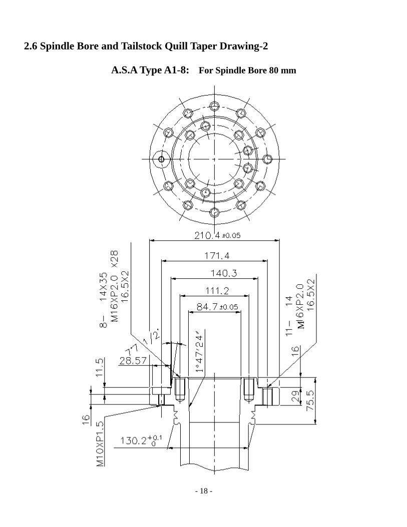
2.6 Spindle Bore and Tailstock Quill Taper Drawing-2
A.S.A Type A1-8: For Spindle Bore 80 mm
M
- 19 -
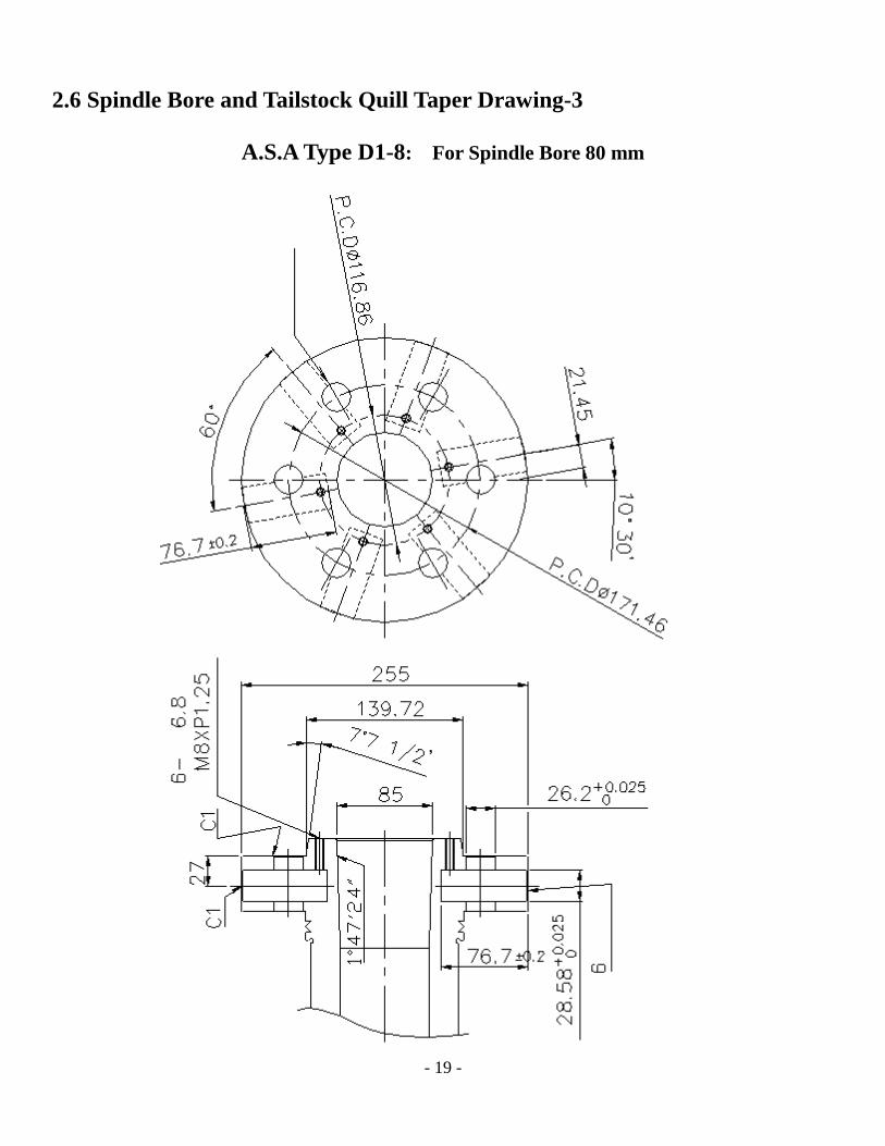
2.6 Spindle Bore and Tailstock Quill Taper Drawing-3
A.S.A Type D1-8: For Spindle Bore 80 mm
- 20 -
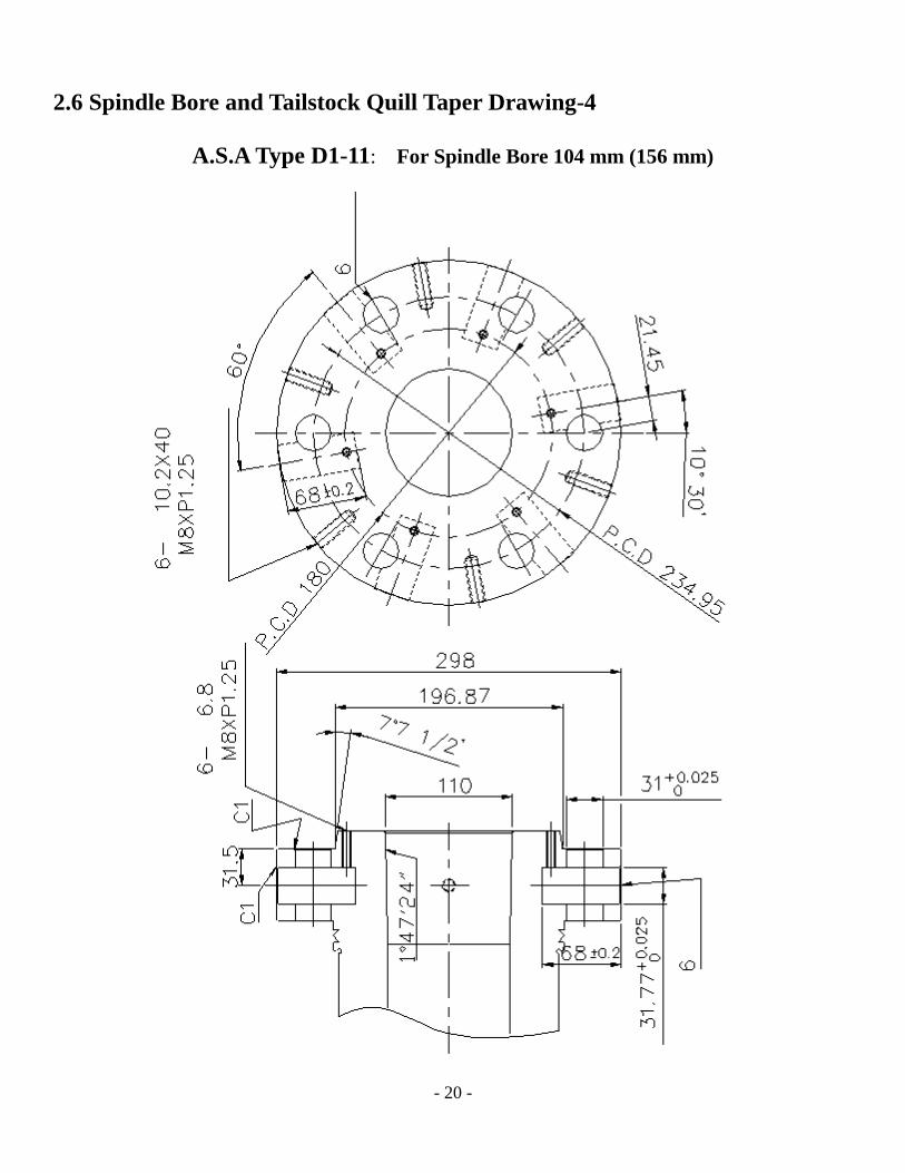
2.6 Spindle Bore and Tailstock Quill Taper Drawing-4
A.S.A Type D1-11: For Spindle Bore 104 mm (156 mm)

- 21 -
2.7 Quill Bore and Quill Taper Specifications: MT5

- 22 -
CHAPTER 3: Preparations before Installing the Machine
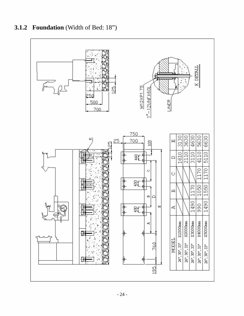
3.1 Foundation Requirements A firm, steady, well constructed ground and good level are essential for precision turning. The heat from sunshine and machine vibration might influence precision turning. A good foundation for the machine requires:
1. No sunlight shining directly on the machine. 2. Do not install the lathe near a press, etc... 3. Good ventilation.
Note: The lathe may be leveled and used free standing (refer to sec. 4.2.2), however, in order to obtain the best performance, it is recommended to install the machine with foundation bolts as shown in the foundation drawing (p. 24).

- 23 -
3.1.1 Dimensional Drawing (Width of Bed: 18”)
MODEL 26 / 30 / 33 1500mm 2000mm 3000mm 4000mm 5000mm
A 3130mm 3630mm 4630mm 5630mm 6630mm
1420( 670) , 1530( 770, 840)
1210(670),1260(770),1295(840)
A
(26) 30, 33)
(26)
(3
0)
(33)
- 24 -
3.1.2 Foundation (Width of Bed: 18”)
- 25 -
3.2 Power Requirements
Harmonics: Harmonic distortion is not to exceed 10% of the total r.m.s. voltage between the live conductors for the sum of the 2nd through 5th
harmonics.
Voltage unbalance in 3-phase supplies:
Neither the voltage of the negative sequence component nor the voltage of the zero sequence component shall exceed 2% of the positive sequence component
Voltage impulses: Not to exceed 1.5 ms in duration with a rise/fall
time between 500 ns and a peak value of no more than 200% of the rated r.m.s. supply voltage.
Voltage interruption: Supply interrupted or at zero voltage for no more
than 3 ms. At any random point in the supply cycle there should be more than 1 s between successive interruptions
Voltage dips: Voltage dips should not exceed 20% of the peak
voltage supply for more than one cycle. There should be more than 1 s between successive dips.
3.3 Site Location
1. Temperature: Normal operating temperature is 50-100°F. For precision turning, please
maintain a room temperature of 68~72°F.
2. Humidity: 30% to 95%
3. Keep away from gases, chemicals, ashes, acids, and salty or explosive substances.
4. Environment brightness: more than 300 LUX.

- 26 -
CHAPTER 4: Transportation and Installation
4.1 Transportation Warning: Always ensure that the capacity of the lifting equipment is adequate before
attempting to lift the machine.
4.1.2 Preparation and Safety Checks
1. All equipment should be examined by one person only.
2. Slings must be visually examined.
3. Operator must be qualified.
4. Operator should keep away when lifting. Do not allow any person to stand under
the machine.
5. Ensure that the eyebolts and securing screws of the lifting equipment are tightened
correctly.
6. Remove all loose items.
7. Clamp the tailstock securely to the tail end of the bed.
8. Clamp the saddle to the bed.

4.1.3 Lifting Procedure

- 28 -
4.2 Installation
4.2.1 Cleaning All machine surfaces are covered with an antirust preservative and must be thoroughly cleaned off before moving any parts. Only mild solvent and soft rags should be used for cleaning. Leave the carriage and tailstock locked in position until exposed bedways are cleaned. Using a good grease solvent, thoroughly remove the rust-preventive from exposed bedways, tops, slides, and from all other machine surfaces. Next, loosen the carriage lock screw and move the carriage to a clean section of the bed. Loosen the tailstock clamp lever, move the tailstock, and finish cleaning the bed ways. Use a stiff bristle brush (not wire) to clean the lead screw and carriage rack. Apply a light coating of machine oil to all machine surfaces for rust protection. For long machine life, be sure to make it a habit to clean and lubricate the machine regularly. Note:
1. Special care must be taken to completely clean the lead screw, feed shafts, slide way, spindle nose, and quill nose.
2. Remove all moisture absorbent silica gel bags from machine and inside the electrical cabinet.
3. The rust preventative coating is removed best by using solvent applied with a clean brush. Once the coating is softened, remove with clean rags. Remove rust preventative before moving slide way.
4.2.2 Level Adjustment
In order for the machine to perform accurately, it must be leveled firmly and precisely. For best results, mount the lathe on a concrete floor (refer to Chapter 3). Once the machine is set on the prepared foundation, and the bed ways and slides are cleaned thoroughly, the machine is ready to be leveled. The level should be used alternately on the cross slide and the sideways of the lathe. Readings of the level should be taken on the extreme ends of the sideways as well as in the center. Minor adjustments to leveling bolts should be made until the machine is perfectly leveled within 0.04mm/m. Once the lathe is leveled correctly, immediately grout the machine base to the foundation using the highest quality, shock-vibration-resistant mortar.
- 29 -
4.2.3 Power Source Wiring The electrical equipment supplied varies depending on the model and personalized requirements. The machine is ready for installation on a 3 phase or single phase, A. C. voltage. Power wiring should be connected to terminals “L1, L2, L3, & PE” in the electrical box. After wiring, check the spindle for proper rotation direction. Turn on the power source switch and push the jog button to confirm forward rotation. If the spindle rotates in the wrong direction, replace two of the three wires (L1, L2, & L3) and check the rotation again. If the spindle speed drops to zero during normal operation, but the pilot light is still on, then the overload thermal relay is not working properly. Turn off the main switch, reset the thermal overload relay, and restart the machine. Warning:
1. Check motor voltage, phase, and cycles before connecting the machine to a power source. 2. Make sure that the power supply is properly fused and the earth circuit is adequate. 3. Motor rotation must be clockwise, as shown on the cover of the motor. If the motor
runs in the wrong direction, interchange two terminals for phase correction.
4.2.4 Dismantling of the Machine
The dismantling procedure is the reverse of the installation procedure.

- 30 -
4.3 Chuck Mounting
Ensure that the surfaces on both the nose and the attachment have been scrupulously cleaned. Mount the attachment on to the spindle nose so that reference marks (R) and (R1) are in line (refer to Fig. 4.3-1). Lock each cam by turning it clockwise using the key provided. Check for correct locking positions. Each cam must be tightened with the index line between the two V marks on the nose (refer to Fig. 4.3-2). Remove lock screw (B) to adjust cam lock studs and turn stud (A) one full in or out turn as required. Re-fit and tighten lock screw (B). Note datum ring (C) marked on each stud as a guide to the original setting.
LOCK NUT
I
V
V
LOCK NUT
Figure 4.3-1
Figure 4.3-2
Figure 4.3-3
Cam Lock
Cam Lock
A B
C

- 31 -
CHAPTER 5: Operation and Use
5.1 Spindle Speed Change
Select the appropriate spindle speed from the spindle speed chart located on top of the headstock, as shown below. There are 12 steps in the range of spindle speeds.
To select the main spindle speed, use lever (1) and lever (2). Lever (1) selects H,M, and L positions. Lever (2) selects speeds of 12 grades corresponding with lever (1). Please refer to Fig. 5.1-1.
Warning: Turn off the motor and let the spindle stop before changing the position of levers
SPINDLE SPEED CHART (Rpm’s under 60 HZ)
For: 3”, 4”, 6”, and 9” Spindle Bores
LEVER H M L
3” 1200 725 470 280 192 112 89 48 72 42 31 17
4” 1000 625 406 240 165 96 72 42 62 36 26 15
6” 800 493 332 192 120 74 50 29 58 34 23 13
9” 600 335 232 120 90 57 39 20 45 28 19 10
2
1
Figure 5.1-1

- 32 -
5.2 Description of Driving Unit
Item Driving Unit Item Driving Unit 1 Spindle speed change lever 8 Feed and thread change lever 2 Spindle speed change lever 9 Engage and disengage champing lever 3 Feed and lead screw F/R grip 10 Main switch 4 Feed and thread change lever 11 Coolant pump switch 5 Feed and thread change lever 12 Longitudinal feed hand wheel 6 Inch and metric (feed) change lever 13 Cross feed hand wheel 7 Inch and metric change lever 14 Longitudinal/cross feed change lever
25
22 24
27
26
23
20A 5
8
9
6
7 4
9A
17
14
21
16
12
15
13
19 18
14A
1 3
2
20 11 10

- 33 -
(Previous Chart Continued)
Item Driving Unit Item Driving Unit 15 Overload adjusting bolt 22 Tailstock body clamping lever 16 Half-nut lever 23 Tailstock hand wheel 17 Feed engagement/disengagement
lever 24 Lead screw
18 Compound feed hand wheel 25 Feed rod 19 Tool post clamping lever 26 Start-up rod 20 Emergency stop button 27 Longitudinal feed stopping rod 21 Start-up lever

- 34 -
5.3 Feeds and Threads (Refer to pages 32-33)
Introduction 1. Spindle Speed Change Lever: Select the H.M.L position to decide the spindle speed. 2. Spindle Speed Change Lever: Select from 12 speed grades using this lever (2). 3. Feed and Lead Screw F/R Grip: Select the forward or backward direction of the lead
screw. 4. Feed and Thread Change Lever: Select the “C” or “D” position using levers (5) and (8)
to adjust feeding and threading .rates. 5. Feed and Thread Change Lever: Select the “A” or “B” position using levers (4) and (8)
to adjust feeding and threading rates. If you want to select the modular threads (feeds), please change the gears as shown in the table.
6. Feed and Thread Change Lever: Select the “E,” “F,” “G,” and “H” positions using
levers (5), (8), and (4) to determine feeding and threading rate. 7. Inch and Metric Change Lever: Select the “W” “M” or neutral position using lever (6)
to choose between inch and metric feeding rates. For example, when selecting metric threads, levers (6) and (7) must be placed in “M” position. The feed rod (25) can be rotated, but the lead screw (24) can not be rotated to complete thread process.
8. Feed and Thread Change Lever: Select from positions “1”-“9” using levers (4) and (5)
to determine feed and thread rates. 9. Engaging and Disengaging the Clamping Cover: Turn the clamping lever (9)
clockwise to engage the lead screw (24) and feed rod (25). Turn lever (9) counterclockwise to disengage the lead screw (24) and feed rod (25).
10. Main Switch: When turned on, the pilot lamp will light up. To start up the main spindle,
shift lever (21) located to the right of the apron and below the chuck guard. 11. Coolant Pump Switch: When turned on, the pilot lamp will light up. Open the valve on
coolant nozzle to allow coolant to flow. Switch off the coolant pump when the cutting

- 35 -
process is completed. 12. Longitudinal Feed Hand Wheel: To move longitudinal feed by hand, turn hand wheel
(12). Be mindful of headstock and tailstock boundaries.
13. Cross Feed Hand Wheel: To move cross feed by hand, use hand wheel (13). Turn the hand wheel (13) clockwise to feed the cross slide forward. The dial on the hand wheel is graduated in 0.05mm increments (metric screw).
14. Longitudinal Cross-Feed Change Lever: Lever (14) selects rapid longitudinal or rapid
cross feed. Pull it outwards for rapid cross feed and pushing down and hold lever (14A) for rapid travel. There is a neutral position between the in and out position of the lever (17) which is used when threading a work piece and pushing down the hair-nut lever (16).
15. Overload Adjusting Bolt: There is an overload safety device used to disengage power
cutting by means of cone clutch mechanism and is adjusted with bolt (15). Turn the bolt clockwise to allow the overload mechanism to handle a greater load during the cutting process before kicking out. Please do not adjust bolt (15) in excess of the machine’s capacity.
16. Half-Nut Lever: When all thread cutting processes have been prepared, push down the
half-nut lever (16) to begin thread cutting the work piece. Pulling lever (16) up disengages the lead screw and stops the thread cutting process.
Note: At the end of the thread cutting process, please pull up the lever (16) and simultaneously turn the cross hand wheel (13) backwards.
17. Feed Engagement and Disengagement Lever: The engaging and disengaging of
longitudinal or cross feeding is accomplished with the lever (17). Pushing down the lever (17) engages the feed rod (25) which powers the cross feed or longitudinal feed. Use the feed change lever (14) to choose longitudinal or cross feeding.
18. Tool Slide Feeding Hand Wheel: To move the tool slide longitudinally, turn the hand
wheel (18) continuously by hand. Turn the hand wheel (18) clockwise to move the compound slide forwards. The dial on the hand wheel is graduated in 0.02mm increments (metric screw).

- 36 -
19. Tool Post Clamping Lever: Turn the clamping lever (19) clockwise to clamp the tool post located on top of the cross slide. The maximum size cutting tool that will fit on the tool post is 25mm x 25mm.
20. Emergency Stop Button: In case of an emergency, quickly push down one of the
emergency stop buttons which are located on the headstock and apron box. The emergency stop button must be disengaged before restarting spindle rotation.
20A.Tailstock Spindle Clamping Lever: Turn the lever (20) counter clockwise to clamp the
tailstock quill. Note: When using a tailstock center to support a work piece, please clamp the quill with
clamping lever (20) and clamp the tailstock body with clamping lever (22).
21. Start-Up Lever: The start-up lever (21) has a safety locking device designed to prevent unintended starting of the spindle. To operate the lever and start the spindle, pull the lever (21) horizontally to disengage a safety pin and then up to start forward (counter clockwise) spindle rotation (be sure the main power switch is on). When the lever (21) is turned down, the spindle rotates in reverse (clockwise).
22. Tailstock Body Clamping Lever: Turn the lever (22) counter clockwise to clamp the
tailstock body. Note: When using a tailstock center to support a work piece or drill bit, and when
transporting the lathe, please clamp the tailstock body with lever (22). 23. Tailstock Hand Wheel: To move the tailstock spindle, turn hand wheel (23)
continuously by hand. Note: Do not allow the tailstock spindle, center, or cutting tool to touch the chuck.
24. Lead Screw: Please see the above description. 25. Feed Rod: Please see the above description. 26. Start-Up Rod: Please see the above description. 27. Longitudinal Feed Stopping Rod: The stopping rod has a ring with 4 settings whose
purpose is for 4 step automatic feed stopping. Select different ring position settings with the stopping lever. The stopping lever is set at “1 label” position, the longitudinal power

- 37 -
feeder will be stopped until the Stopping-Arm touches the first ring setting.
- 38 -
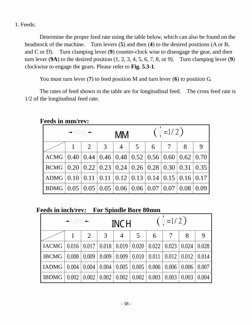
1. Feeds:
Determine the proper feed rate using the table below, which can also be found on the headstock of the machine. Turn levers (5) and then (4) to the desired positions (A or B, and C or D). Turn clamping lever (9) counter-clock wise to disengage the gear, and then turn lever (9A) to the desired position (1, 2, 3, 4, 5, 6, 7, 8, or 9). Turn clamping lever (9) clockwise to engage the gears. Please refer to Fig. 5.3-1.
You must turn lever (7) to feed position M and turn lever (6) to position G.
The rates of feed shown in the table are for longitudinal feed. The cross feed rate is 1/2 of the longitudinal feed rate.
INCH ( =1/ 2
1 2 3 4 5 6 7 8 9 IACMG 0.016 0.017 0.018 0.019 0.020 0.022 0.023 0.024 0.028 IBCMG 0.008 0.009 0.009 0.009 0.010 0.011 0.012 0.012 0.014 IADMG 0.004 0.004 0.004 0.005 0.005 0.006 0.006 0.006 0.007 IBDMG 0.002 0.002 0.002 0.002 0.002 0.003 0.003 0.003 0.004
MM ( =1/ 2
1 2 3 4 5 6 7 8 9 ACMG 0.40 0.44 0.46 0.48 0.52 0.56 0.60 0.62 0.70 BCMG 0.20 0.22 0.23 0.24 0.26 0.28 0.30 0.31 0.35 ADMG 0.10 0.11 0.11 0.12 0.13 0.14 0.15 0.16 0.17 BDMG 0.05 0.05 0.05 0.06 0.06 0.07 0.07 0.08 0.09
Feeds in mm/rev:
Feeds in inch/rev: For Spindle Bore 80mm

- 39 -
2. Threads Find the desired threading dimensions from the thread table below (located on the
headstock), then set levers (4), (5), (6), (7), (8), and (9) accordingly.
DP 1 2 3 4 5 6 7 8 9
ADWF 4 4½ 4¾ 5 5½ 5¾ 6 6½ 7 BDWF 8 9 9½ 10 11 11½ 12 13 14 ACWF 16 18 19 20 22 23 24 26 28 BCWF 32 36 38 40 44 46 48 52 56
MP 1 2 3 4 5 6 7 8 9
ACME 4 4.5 4.75 5 5.5 5.75 6 6.6 7 BCME 2 2.25 2.5 2.75 3 3.25 3.5 ADME 1 1.25 1.5 1.75 BDME 0.5 0.75
1 in 1 2 3 4 5 6 7 8 9
ADWF 2 2¼ 23/ 2½ 8 2¾ 27/ 3 8 3¼ 3½ BDWF 4 4½ 4¾ 5 5½ 5¾ 6 6½ 7 ACWF 8 9 9½ 10 11 11½ 12 13 14 BCWF 16 18 19 20 22 23 24 26 28
mm 1 2 3 4 5 6 7 8 9
ACME 8 9 9.5 10 11 11.5 12 13 14 BCME 4 4.5 4.75 5 5.5 5.75 6 6.5 7 ADME 2 2.25 2.5 2.75 3 3.25 3.5 BDME 1 1.25 1.5 1.75 ACMH 6.4 7.2 7.6 8 8.8 9.2 9.6 10.4 11.2 BCMH 3.2 3.6 3.8 4 4.4 4.6 4.8 5.2 5.6 ADMH 1.6 1.8 1.9 2 2.2 2.3 2.4 2.6 2.8 BDMH 0.8 0.9 0.95 1 1.1 1.15 1.2 1.3 1.4
9
6 8
7 5 4
Figure 5.3-1

- 40 -
5.4 Carriage and Apron
The carriage moves along the bed by hand and power feed, and supports the cross slide, compound rest, tool post and cutting tools. The cross slide handle (A) and tool post slide handle (B) move the cross slide and tool post slide in and out. The apron, which is anchored to the front of the carriage, contains the power longitudinal and cross feed controls. The engagement and disengagement of longitudinal and cross feeding is accomplished by lever (C) (drop worm system). Lever (D) determines the engagement of the power longitudinal and cross feeds. There is a neutral position between the pull out and push in positions. The interlocking devices are equipped so that the longitudinal feed and the half-nut engaging can not work together. There is an overload safety device that operates by means of a cone clutch, which can be easily adjusted by a screw (E).
D
E
C
B
A
- 41 -
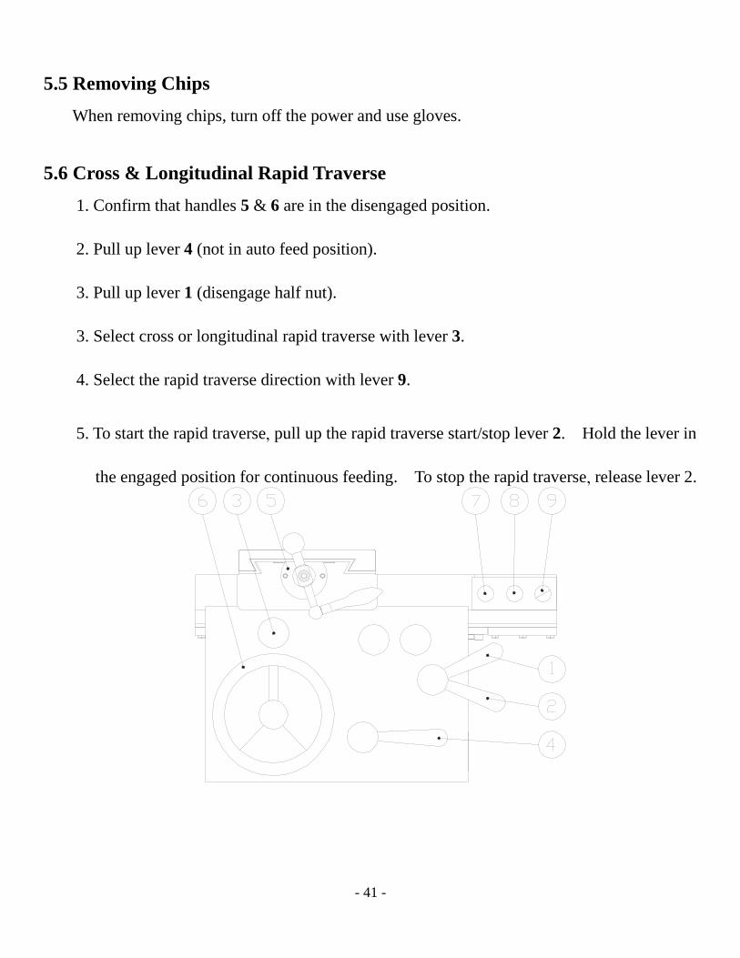
5.5 Removing Chips
When removing chips, turn off the power and use gloves.
5.6 Cross & Longitudinal Rapid Traverse 1. Confirm that handles 5 & 6 are in the disengaged position. 2. Pull up lever 4 (not in auto feed position). 3. Pull up lever 1 (disengage half nut). 3. Select cross or longitudinal rapid traverse with lever 3. 4. Select the rapid traverse direction with lever 9.
5. To start the rapid traverse, pull up the rapid traverse start/stop lever 2. Hold the lever in
the engaged position for continuous feeding. To stop the rapid traverse, release lever 2.

- 42 -
CHAPTER 6: Maintenance
6.1 Lubrication
It is most important to lubricate the lathe before operating. The operator should be made responsible for the proper lubrication of the lathe. The grade and quality of lubricants are given on the following oil lubrication chart (p. 42). The instructions on this chart are essential to the proper oiling of the internal parts of the lathe. Oil levels should be strictly observed. It is of primary importance for proper operation and long life of the machine that the oil bath for the headstock always be filled to the appropriate level.
Note: 1. Headstock and gear box are lubricated by an automatic oil system. 2. Isolate the machine before removing any covers (guards) and making any adjustments. 3. Apron is oil bathed and equipped with an automatic pump for lubrication. The oil will be forced to the oil grooves of carriage and then flow to the bed way and the cross slide way.
- 43 -
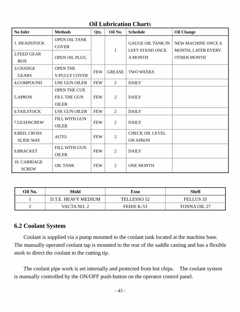
Oil Lubrication Charts No Inlet Methods Qty. Oil No. Schedule Oil Change
1. HEADSTOCK OPEN OIL TANK COVER
1 GAUGE OIL TANK IN LEFT STAND ONCE A MONTH
NEW MACHINE ONCE A MONTH, LATER EVERY OTHER MONTH
2.FEED GEAR BOX
OPEN OIL PLUG
3.CHANGE GEARS
OPEN THE V-PULLY COVER
FEW GREASE TWO WEEKS
4.COMPOUND USE GUN OILER FEW 2 DAILY
5.APRON OPEN THE CUP, FILL THE GUN OILER
FEW 2 DAILY
6.TAILSTOCK USE GUN OILER FEW 2 DAILY
7.LEADSCREW FILL WITH GUN OILER
FEW 2 DAILY
8.BED, CROSS SLIDE WAY
AUTO FEW 2 CHECK OIL LEVEL ON APRON
9.BRACKET FILL WITH GUN OILER
FEW 2 DAILY
10. CARRIAGE SCREW
OIL TANK FEW 2 ONE MONTH
Oil No. Mohl Esso Shell 1 D.T.E. HEAVY MEDIUM TELLESSO 52 FELLUS 33 2 VACTA NO. 2 FEHIS K-53 TONNA OIL 27
6.2 Coolant System
Coolant is supplied via a pump mounted to the coolant tank located at the machine base. The manually operated coolant tap is mounted to the rear of the saddle casting and has a flexible stork to direct the coolant to the cutting tip. The coolant pipe work is set internally and protected from hot chips. The coolant system is manually controlled by the ON/OFF push-button on the operator control panel.

- 44 -
Warning: 1. Isolate the machine before removing any covers and making adjustments. 2. The following precautions should be taken:
a. Avoid unnecessary contact with cutting fluid. b. Wear protective clothing during operation. c. Change cutting fluids regularly. d. Dispose of fluids in accordance with statutory regulation. e. Avoid mixing different types of cutting fluids.
6.2.1 Coolant System Filling Procedure
1. Transverse the saddle to the tail end of the machine. 2. With a suitable pipe to assist filling, fill the tank to within 1 cm(3/8” of the top. 3. Clean any over spill on the floor immediately. 4. Power up the machine, open the coolant tap and run coolant pump to prime the system.
6.2.2 Coolant System Cleaning Procedure
1. Transverse the saddle to the tail end of the machine. 2. Using the machine coolant pump, the coolant can be pumped out into a suitable container. 3. Close the tap at the standpipe and power down the machine. 4. The coolant pipe and electrical cable attached to the pump will have excess length which
can be pulled through. 5. Slide the coolant tank approximately 650mm out the end of the machine and wedge the
opposite end of the tank upward. The remaining liquid can be removed and the bottom of the tank wiped clean.
6. Clean any overspill on the floor immediately. 7. Re-fit the coolant tank and fill to within 1 cm(3/8”)from the top. 8. Power up the machine, open the coolant tap and run the coolant pump to prime the
system.
6.2.3 Coolant Capacities and Recommended Types for Ferrous Metal
Capacity Esso Shell Mobil Castrol Cut well 30 Dromus oil B SOLVAC Syntilor

- 45 -
1535 Coolant

- 46 -
6.3 Routine Maintenance Program A regular program of preventative maintenance is recommended to keep the machine in good working order. This will reduce service calls and cost to you.
Area Attachment Item check Method of check
Permissible condition Action if required
Headstock Bearings and gears Lubrication Visual Level indicated on oil sight
Top use replace oil annually
Tailstock Lubrication Lubricate weekly See lubrication checks Top slide Lubrication Lubricate weekly See lubrication checks Coolant Level Visual 50mm below top of
tank Top up see coolant filling
Area Attachment Item check Method of check
Permissible condition
Action if required
Headstock Spindle Alignment Test bar See accuracy chart
Re-align by service engineer
Tailstock Body set over Test bar and test indicator
See accuracy chart
Re-align
Area Attachment Item check Method of check Permissible condition Action if required Headstock Spindle drive
belts Tension Tension test tool See belt tensioning
tables See belt tensioning section
Saddle Taper gibs Slide way clearance
Dial test indicator
Crosslide Taper gib strip
Slide way clearance
Dial test indicator
6.3.3 Annual Checks
6.3.2 Half Year Checks
6.3.1 Weekly Checks

- 47 -
Trouble Shooting Chart TROUBLE PROBABLE CAUSE CORRECTION
Vibration
1. Loose leveling screws 2. Torn or mismatched V-belts 3. Work or chuck out of balance at
high spindle speeds 4. Motor out of balance
1. Set all screws so they bear evenly on leveling plates. 2. Replace V-belts with matched set. 3. Balance chuck or reduce spindle speed 4. Contact local representative of motor manufacturer.
Chatter
1.Tool bit improperly ground or not on center
2. Tool overhang is too great 3. Using improper feed surface 4. Feed rate too high or too low 5. Gibs of cross slide or compound
rest are loose 6. Spindle bearings are worn out
1. Regrind tool bit or adjust tool holder so that the area of contact between the tool bit and the work piece is decreased. Avoid an extreme negative rake angle.
2. Keep the point of the tool bit as close as possible to the tool holder.
3. Reduce or increase spindle speed. 4. Reduce or increase feed rate. 5. Adjust gibs. 6. Adjust spindle bearings
Chatter (cont’d)
1. Work improperly supported. 2. Vibration. 3. Spindle bearing loose.
1. Adjust tailstock center. Use steady rest or follow rest on long, slender, shaft work pieces.
2. Minimize tailstock barrel extension. (See “Vibration” trouble above).
3. Adjust spindle bearings.
Work not turning straight
1. Headstock and tailstock centers are not aligned properly
2.Work improperly supported 3. Bed not level 4. Tool not on center when using
taper attachment
1. Align tailstock center. 2. Use steady rest or follow rest. 3. Reduce bed using precision level. 4. Put tool on center
Work out of round
1. Work loose between centers or centers are excessively worn-work out of round
2. Loose headstock spindle bearings
1. Adjust tailstock center. Regrind centers. Lap work centers.
2. Adjust headstock spindle bearings
6.4 Trouble Shooting
- 48 -
CHAPTER 7: Adjustment Warning: Isolate the machine before removing any covers/guards and making adjustments
7.1 Leveling Adjustment of Bed As the work piece accuracy mostly depends on the bed leveling, recheck the level of the bed frequently. Adjustments should be made according to the illustrations in section 4.2: Installation (p.?).
7.2 Adjustment of Main Spindle Bearings The spindle bearings have been preloaded at the factory and seldom require adjusting. If one or more of the following occurs, the spindle bearings may need adjustment:
1. The spindle spins too freely, or play is noticeable when the spindle is pushed back and forth
2. Bearing noise or chattering is heard 3. Over heating of main spindle.
Properly adjust rear and front bearings by loosening or tightening the nut on the spindle bearing rear cover. It is necessary to make an adjustment only when the spindle has reached operating temperature. To achieve operating temperature, run spindle at medium speed for about one hour.

- 49 -
7.3 Adjustment of Taper Gib
There is a taper gib in the cross slide and tool post slide respectively. Adjust the taper gibs with the following procedure: To adjust the gib adjusting screws (1) and (2) evenly until the slides move with a slight drag, then tighten the gib lock screw (3).
7.4 Eliminating Back-Lash of Cross Slide and Tool Post Slide There are female screws that can be adjusted to minimize the back-lash of the cross slide screw and tool post slide screw. Loosen bolts (4) to some extent and tighten the adjusting screw (5) with a wrench, then the cross slide back-lash should be eliminated. Tighten the adjusting screw (6) to eliminate the backlash of the tool post slide.
7.5 Adjustment of Carriage Gibs If horizontal play develops between the carriage and bed, adjust the four gib adjusting screws (7) evenly at the rear of the carriage until it moves on the bed with only a slight drag.
- 50 -
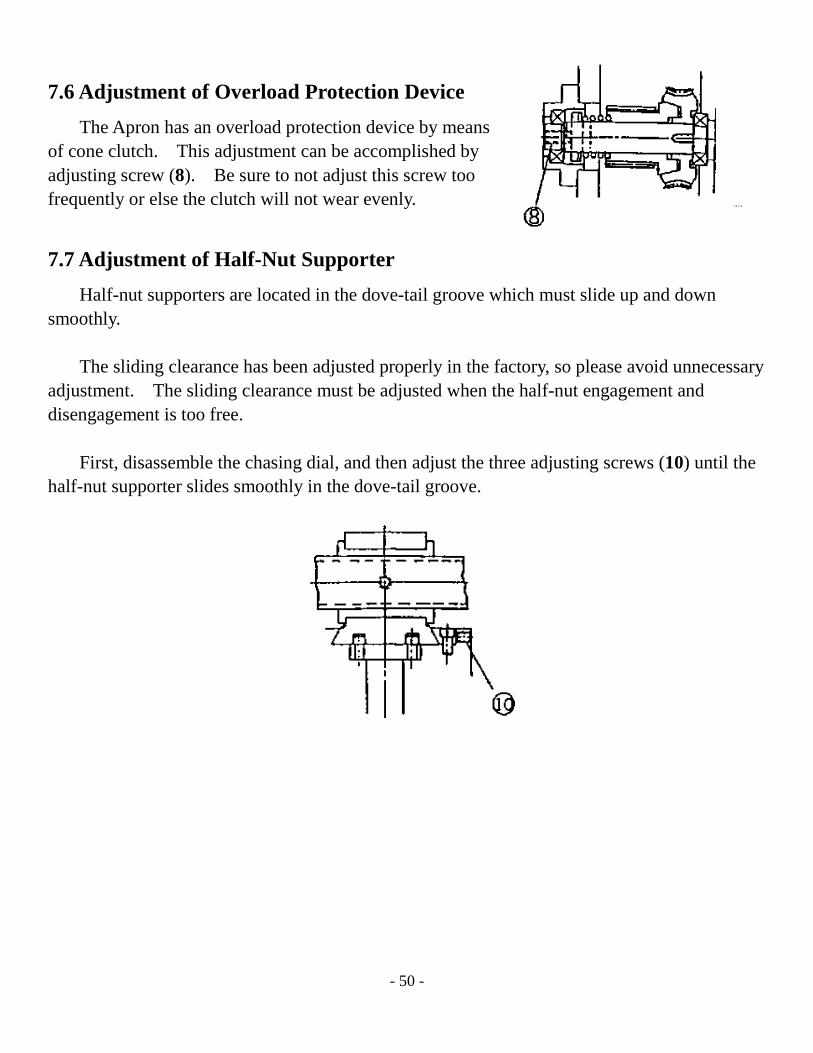
7.6 Adjustment of Overload Protection Device
The Apron has an overload protection device by means of cone clutch. This adjustment can be accomplished by adjusting screw (8). Be sure to not adjust this screw too frequently or else the clutch will not wear evenly.
7.7 Adjustment of Half-Nut Supporter Half-nut supporters are located in the dove-tail groove which must slide up and down smoothly. The sliding clearance has been adjusted properly in the factory, so please avoid unnecessary adjustment. The sliding clearance must be adjusted when the half-nut engagement and disengagement is too free. First, disassemble the chasing dial, and then adjust the three adjusting screws (10) until the half-nut supporter slides smoothly in the dove-tail groove.

- 51 -
7.8 Correcting Tailstock Alignment First, place a 300mm ground steel test bar between spindle and tailstock centers. Fit a dial indicator to the tool post and transverse the center line length of the bar to confirm alignment. No end-to-end vibration should exist. Then, correct the alignment error shown on the indicator by the following procedure: Release the tailstock clamp lever (B) and adjust the set-over screw (A), shown in the diagram. The following refers to the readings at the tailstock end of the ground test bar. If the diameter of the test bar is greater, slacken screw (1) and tighten screw (2). Continue checking and adjusting until end-to-end readings of indicator are the same. If taper turning is carried out, apply the above procedure to regain the parallel condition.
1
2

- 52 -
Wiring Diagram

- 53 -
CHAPTER 8: Electrical Circuit
- 54 -
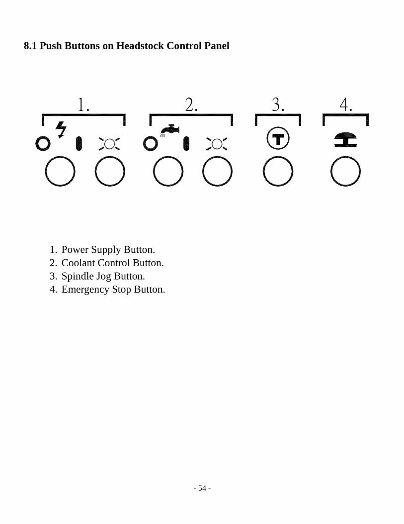
8.1 Push Buttons on Headstock Control Panel
1. Power Supply Button. 2. Coolant Control Button. 3. Spindle Jog Button. 4. Emergency Stop Button.
1. 2. 3. 4.

- 55 -
CHAPTER 9: Diagrams & Part Lists

- 56 -
Headstock-1

- 57 -
Headstock-2
- 58 -
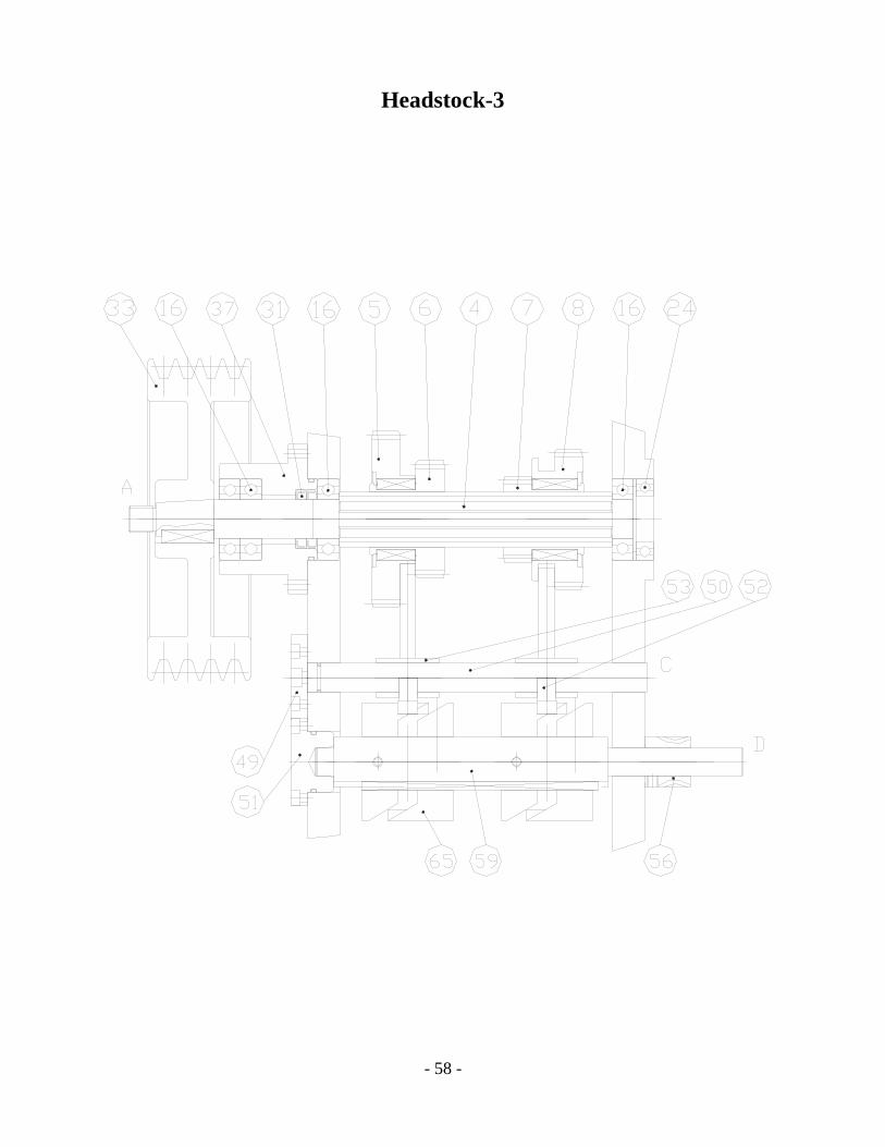
Headstock-3
- 59 -
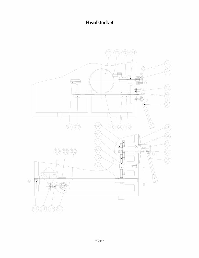
Headstock-4

- 60 -
Headstock Item Part No. Description Qty.
1 26H-001-4 HEADSTOCK CASE 1 2 26H-002 TOP COVER 1 3 26H-003-4 MAIN SHAFT 1 4 26H-004 SIX-FLUTED SHAFT 1 5 26H-005 GEAR 1 6 26H-006 GEAR 1 7 26H-007 GEAR 1 8 26H-008 GEAR 1 9 26H-009 GEAR 1 10 26H-010 GEAR 1 11 26H-011 GEAR 1 12 26H-012 GEAR 1 13 26H-013 GEAR 1 14 26H-014 SIX-FLUTED SHAFT 1 15 26H-015 GEAR 1 16 6206# BEARING 3 17 26H-017 GEAR 1 18 26H-018 SHAFT 1 19 26H-019-4 GEAR 1 20 26H-020-4 GEAR 1 21 26H-021-4 GEAR 1 22 26H-022-4 REVERSING GEAR 1 23 26H-023 GEAR 1 24 6007# BEARING 2 25 6207# BEARING 1 26 6009# BEARING 1 27 6306# BEARING 1 28 6024# BEARING 1 29 26H-029-4 GEAR 1 30 26H-030 F-SHAFT 1 31 453008 OIL SEAL 1 32 6025# BEARING 1 33 26H-033-4 PULLEY 1 34 32026# BEARING 1 35 32028# BEARING 1 36 26H-036 SHAFT CUP 1 37 26H-037-4 INPUT SHAFT CUP 1

- 61 -
Item Part No. Description Qty. 38 26H-038-4 INPUT SHAFT CUP 1 39 26H-039-4 REAR COVER 1 40 26H-040-4 FRONT COVER 1 41 26H-041 SHAFT SLEEVE 1 42 26H-044 SHAFT CUP 1 43 26H-045-4 SHAFT CUP 1 44 26H-049A-4 NUT 1 45 26H-049B-4 NUT 1 46 26H-050-4 WASHER 1 47 26H-052 SLEEVE 1 48 26H-059 SHIFTING LEVER 1 49 26H-060 POSITION SHAFT CAP 1 50 26H-061 POSITION FLUTED SHAFT 1 51 26H-062 POSITION SHAFT CAP 1 52 26H-063 PILLAR 1 53 26H-064 SHIFT FORK 1 54 26H-066 GEAR FORK 1 55 26H-067 WORM 1 56 26H-068 WORM GEAR 1 57 26H-069 SHIFT GEAR 1 58 26H-070 SHIFT LEVER 1 59 26H-071 CAM SHAFT 1 60 26H-072 WASHER 1 61 26H-074 PLUG 1 62 26H-075 SHIFT GEAR 1 63 26H-076 SHIFT GEAR 1 64 26H-078 SHIFT GEAR 1 65 26H-079 SHIFTING CAM 1 66 26H-080 SHIFT SHAFT SLEEVE 1 67 26H-081 SHIFT BOSS 1 68 26H-082 SHIFT LEVER 1 69 26H-083-4 SPEED DIAL 1 70 26H-086 BOSS 1 71 26H-088 GEAR-SHIFT SHAFT 1 72 26H-089 SHIFT LEVER 1 73 26H-090 SHIFT FORK 1 74 26H-091 BOSS 1 75 26H-091-2 SHIFTING HANDLE 1 76 26H-092 POSITION DIAL 1

- 62 -
Item Part No. Description Qty. 77 26H-095 ROCK ARM 1 78 26H-021-6C GEAR SHAFT 79 26H-021-6B GEAR 80 26H-021-6A GEAR 81 38H-078-6 GEAR CHANGE LEVER 82 38A-039 OPEN-CLOSE LEVER
- 63 -
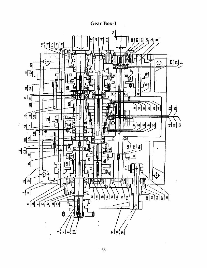
Gear Box-1

- 64 -
Gear Box-2
- 65 -
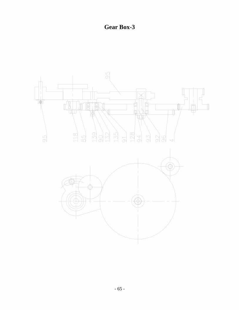
Gear Box-3

- 66 -
Gear Box Item Part No. Description Qty.
1 32001 GEAR BOX CASTING 1 2 32002 COVER 1 3 32003 SHAFT 1 4 32004 GEAR 1 5 32005 WASHER 1 6 32006 FLANGE BEARING 1 7 30007 GEAR 1 8 32008 ROD 1 9 32009 GEAR 1 10 32010 SLIDING BLOCK 1 11 32011 SLIDING BLOCK 1 12 32012 GEAR 1 13 32013 GEAR 1 14 32014 SLIDING BLOCK 1 15 32015 LINK 1 16 32016 GEAR 1 17 32017 CLUTCH 1 18 32018 SLIDING BLOCK 1 19 32019 WASHER 2 20 32020 COVER 1 21 32021 SHAFT 1 22 32022 GEAR 1 23 32023 SHAFT 1 24 32024 COVER 1 25 32025 SHAFT 1 26 32026 COVER 1 27 32027 SHAFT 1 28 32028 GEAR 1 29 32029 GEAR 1 30 32030 SHAFT 1 31 32031 GEAR 1 32 32032 GEAR 1 33 32033 GEAR 1 34 32034 GEAR 1 35 32035 GEAR 1 36 32036 GEAR 1 37 32037 GEAR 1

- 67 -
38 32038 GEAR 1 39 32039 GEAR 1 40 32040 GEAR 1 41 32041 GEAR 1 42 32042 GEAR 1 43 32043 GEAR 1 44 32044 COVER 1 45 32045 SHAFT 1 46 47 32047 GEAR 1 48 32048 COLLAR 1 49 32049 GEAR 1 50 32050 GEAR 1 51 32051 SWING FRAME 1 52 32052 GEAR 1 53 32053 CLUTCH 1 54 32054 SHAFT 1 55 32055 SHAFT 1 56 32056 SLIDING BLOCK 1 57 32057 FORK 1 58 32058 SHAFT 1 59 32059 FLANGE BEARING 1 60 32060 SLIDING BLOCK 1 61 32061 LEVER 1 62 32062 HANDLE 5 63 32063 ROD 5 64 32064 HUB 5 65 32065 ROCKER ARM 1 66 32066 ROCKER ARM 1 67 32067 ROCKER ARM 1 68 32068 ROCKER ARM 1 69 32069 ROCKER ARM 1 70 32070 PIN 1 71 32071 NAME PLATE 1 72 32072 HUB 1 73 32073 GEAR SHAFT 1 74 32074 NAME PLATE 1 75 32075 COVER 1 76 32076 HUB 1 77 32077 HANDLE 1 78 32078 CRANK 1

- 68 -
79 32079 PIN 1 80 32080 GIB 1 81 32081 GIB 1 82 32082 SLIDING PLATE 1 83 32083 LOCATING PLARE 1 84 32084 LOCATING PIN 1 85 32085 SHAFT 1 86 32086 OIL PLUG 1 87 32087 OIL WINDOW 1 88 32088 SWING FRAME 1 89 32089 GEAR 22T 1 90 32090 SHAFT 1 91 32091 GEAR 1 92 32092 SHAFT 1 93 32093 BUSHING 1 94 65013 WASHER 1 95 65014 SCREW 1 96 32096 GEAR 100T 1 97 32097 GEAR 30TX60T 1 101 K06620 KEY 4 102 K06650 KEY 3 103 K06655 KEY 2 104 K06670 KEY 1 105 P11 “O” RING 1 106 P12 “O” RING 1 107 P21 “O” RING 1 108 TC16267 OIL SEAL 1 109 TC32458 OIL SEAL 1 110 Ø5 PIN 6 111 Ø6 SPRING 2 112 ø¼ STEEL BALL 2 113 M6X12 SCREW 1 114 M6X16 SCREW 6 115 M6X20 SCREW 1 116 M6X35 SCREW 2 117 M6X40 SCREW 118 M6X12 SCREW 119 M6X6 SET SCREW 120 M6X8 SET SCREW 121 M6X12 SET SCREW 122 M8X8 SET SCREW

- 69 -
123 AN06 BEARING NUT 124 M10 NUT 125 M12 SCREW 126 30206# BEARING 2 127 6002# BEARING 2 128 6005Z# BEARING 3 129 6006# BEARING 2 130 6006Z# BEARING 1 131 6200# BEARING 1 132 6003Z# BEARING 3 133 6204# BEARING 4 134 6205# BEARING 3 135 6206# BEARING 1 136 S24 CIRCLIP 1 137 S25 CIRCLIP 3 138 S30 CIRCLIP 2 139 S17 CIRCLIP 1 140 R35 CIRCLIP 1

- 70 -
Apron-1 (X & Z Axis Rapid Travel)

- 71 -
Apron-2 (X & Z Axis Rapid Travel)

- 72 -

- 73 -
Apron Box & Threading Dials-1 Item Part No. Description Qty.
1 5-A3001 APRON 1 2 5-A3002 APRON COVER 1 3 5-A3003 SET BED 1 4 5-A3004 U SHAFT 1 5 5-A3005 COLLAR 2 6 5-A3006 U1 GEAR 1 7 5-A3007 W2 GEAR 1 8 5-A3008 W1 GEAR 1 9 5-A3009 W WORN 1 10 5-A3010 WORN WHEEL 1 11 5-A3011 K1 GEAR 1 12 5-A3012 B2 GEAR 1 13 5-A3013 J SHAFT GEAR 1 14 5-A3014 D1 SHAFT 1 15 5-A3015 E1 GEAR 1 16 5-A3016 E2 GEAR 1 17 5-A3017 F1 GEAR 1 18 5-A3018 F SHAFT 1 19 5-A3019 H SHAFT 1 20 5-A3020 B SHAFT GEAR 1 21 5-A3021 A SHAFT 1 22 5-A3022 SHIFTING FORK 1 23 5-A3023 Q1 GEAR 1 24 5-A3024 A1 GEAR 1 25 5-A3025 W3 GEAR & R1 GEAR 2 26 5-A3026 R SHAFT 1 27 5-A3027 H1GEAR 1 28 5-A3028 H2 GEAR 1 29 5-A3029 R BUSHING 1 30 5-A3030 COLLAR 1 31 5-A3031 B SHAFT COVER 1 32 5-A3032 W SHAFT 1 33 5-A3033 E SHAFT 1 34 5-A3034 J SHAFT 1 35 5-A3035 K SHAFT 1 36 5-A3036 D SHAFT 1 37 5-A3037 SHAFT SET BED 1 38 5-A3038 CONNECTING ROD 1

- 74 -
Item Part No. Description Qty. 39 5-A3039 PLATE 1 40 5-A3040 COLLAR 1 41 5-A3041 M SHAFT 1 42 5-A3042 SHIFTING FORK 1 43 5-A3043 SHIFTING FORK 1 44 5-A3044 COVER 1 45 5-A3045 LOCKING ARM 1 46 5-A3046 A2 GEAR 1 47 5-A3047 HANDLE 1 48 5-A3048 SHIFTING FORK 1 49 5-A3049 SCREW 1 50 5-A3050 LOCKING ARM 1 51 5-A3051 COLLAR 1 52 5-A3052 GRADUATION 1 53 5-A3053 G SHAFT & N SHAFT 1 54 5-A3054 SHIFTING FORK 1 55 5-A3055 CAM 1 56 5-A3056 I SHAFT 1 57 5-A3057 BUSHING 1 58 5-A3058 S SHAFT 1 59 5-A3059 SHAFT 1 60 5-A3060 HOLDING 1 61 5-A3061 COLLAR 1 62 5-A3062 BUSHING 1 63 5-A3063 SET BED 1 64 5-A3064 PLATE 1 65 5-A3065 SET BED 1 66 5-A3066 COLLAR 1 67 5-A3067 ON-OFF NUT BED 1 68 5-A3068 BRASS NUT 1 69 5-A3069 HANDLE WHEEL 1 70 5-A3070 SCREW SET BED 1 71 5-A3071 LIMIT SWITCH BED 1 72 5-A3072 I SHAFT BUTTON BED 1 73 5-A3073 GEAR 1 74 5-A3074 B3 GEAR 1 75 5-A3075 D SHAFT COVER 1 76 5-A3076 B1 GEAR 1 77 5-A3077 C SHAFT 1

- 75 -
Item Part No. Description Qty. 78 5-A3078 COLLAR 1 79 5-A3079 COLLAR 1 80 5-A3080 COLLAR 1 81 5-A3081 SET BED 1 82 5-A3082 STEM BED 1 83 5-A3083 HANDLE 1 84 5-A3084 STEM BED 1 85 5-A3085 GUARD 1 86 5-A3086 SHAFT 1 87 5-A3087 DIAL 1 88 5-A3088 WASHER 1 89 5-A3089 WASHER 1 90 5-A3090 GEAR 1 91 5-A3091 GEAR 1 92 5-A3092 GEAR 1 93 5-A3093 GEAR 1 94 5-A3094 GEAR 1 95 5-A3095 GEAR 1 96 5-A3096 BOLT 1

- 76 -
1.I TEM
2.3.4.5.6.7.8.9.10.
14.
18.17.16.15.
13.12.11.
PARTS NO.
Z15G1704
35018600360066004
35004
35009
35013350123501135010
35008350073500635005
350033500235001
Q' TY1.1.1.1.1.1.1.1.1.1.1.1.2.1.2.1.1.1.
PARTS NAME
Shaf tBody
War m Saf tWar m WheelCl ut chBus hHadl e bos sGear Shaf tGear Bus hShaf tHandl e30203 Taper Rol l erMi cr o Swi t chBear i ngBear i ngBear i ngOr ent at i on Gear
RAPI D FEED
RAPI D FEED
617
16
12
718
5
4
115
1189
10
14
13
13
2 3

- 77 -
Carriage & Tool Slide-1
- 78 -
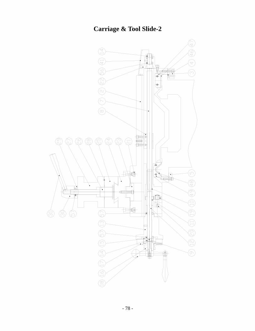
Carriage & Tool Slide-2
- 79 -
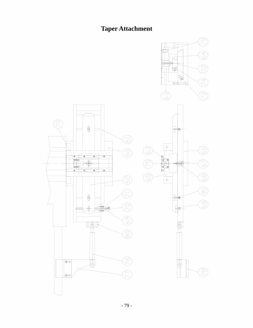
Taper Attachment

- 80 -
Carriage, Tool-Slide, & Taper Attachment Item Part No. Description Qty.
1 26S-001 SADDLE 1 2 26S-002 CROSS SLIDE 1 3 26S-003 REAR LOCKING PLATE 1 4 26S-004 REAR ADIUSTER PLATE 1 5 26S-005 FRONT PRESSING PLATE 2 6 26S-006 FIXED BLOCK 1 7 26S-007 LEAD SCREW 1 8 26S-008 BRASS NUT 1 9 26S-009 SHAFT 1 10 26S-010 SLEEVE 1 11 26S-011 GEAR 1 12 26S-012 BUSH 1 13 26S-013 BRACKET 1 14 26S-014 NUT 1 15 26S-015 SCALE SLEEVE 1 16 26S-016 LOCKING NUT 1 17 26S-017 SCALE RING 1 18 26S-018 HANDLE 1 19 26S-019 GEAR 1 20 26S-020 MIDDLE SHAFT 1 21 26S-021 NUT 1 22 26S-022 REAR BRACKET 1 23 26S-023 SWIVEL SHAFT 2 24 26S-024 BASE 1 25 26S-025 COVER 1 26 26S-026 LOCK BAR 1 27 26S-027 4-WAY TOOL POST 1 28 26S-028 29 26S-029 RING 1 30 26S-030 BOSS 1 31 26S-031 LEVER 1 32 26S-032 LEAD SCREW 1 33 26S-033 LEAD SCREW SET 1 34 26S-034 SHAFT CUP 1 35 26S-035 SCALE RING 1 36 26S-036 BUSH 1 37 26S-037 OIL COVER 1
- 81 -
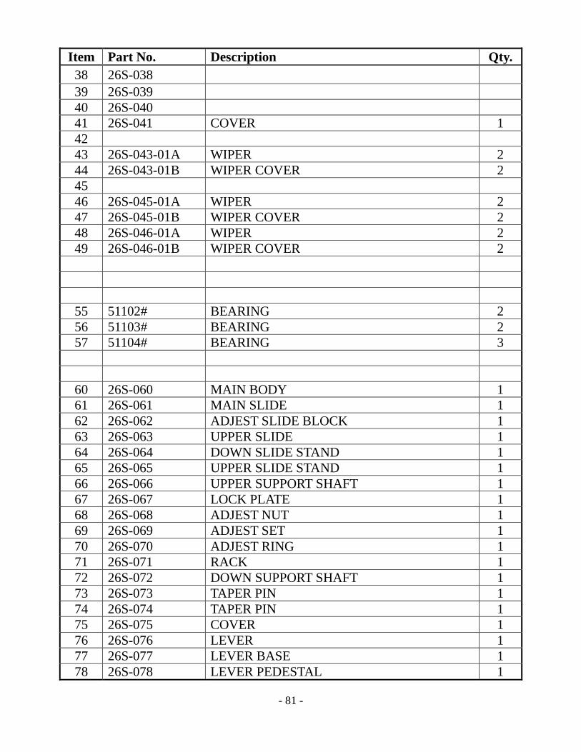
Item Part No. Description Qty. 38 26S-038 39 26S-039 40 26S-040 41 26S-041 COVER 1 42 43 26S-043-01A WIPER 2 44 26S-043-01B WIPER COVER 2 45 46 26S-045-01A WIPER 2 47 26S-045-01B WIPER COVER 2 48 26S-046-01A WIPER 2 49 26S-046-01B WIPER COVER 2
55 51102# BEARING 2 56 51103# BEARING 2 57 51104# BEARING 3
60 26S-060 MAIN BODY 1 61 26S-061 MAIN SLIDE 1 62 26S-062 ADJEST SLIDE BLOCK 1 63 26S-063 UPPER SLIDE 1 64 26S-064 DOWN SLIDE STAND 1 65 26S-065 UPPER SLIDE STAND 1 66 26S-066 UPPER SUPPORT SHAFT 1 67 26S-067 LOCK PLATE 1 68 26S-068 ADJEST NUT 1 69 26S-069 ADJEST SET 1 70 26S-070 ADJEST RING 1 71 26S-071 RACK 1 72 26S-072 DOWN SUPPORT SHAFT 1 73 26S-073 TAPER PIN 1 74 26S-074 TAPER PIN 1 75 26S-075 COVER 1 76 26S-076 LEVER 1 77 26S-077 LEVER BASE 1 78 26S-078 LEVER PEDESTAL 1

- 82 -
Item Part No. Description Qty. 79 26S-079 SET BLOCK 1 80 26S-080 SET BLOCK 1 81 26NCS-044 T-NUT 1
- 83 -
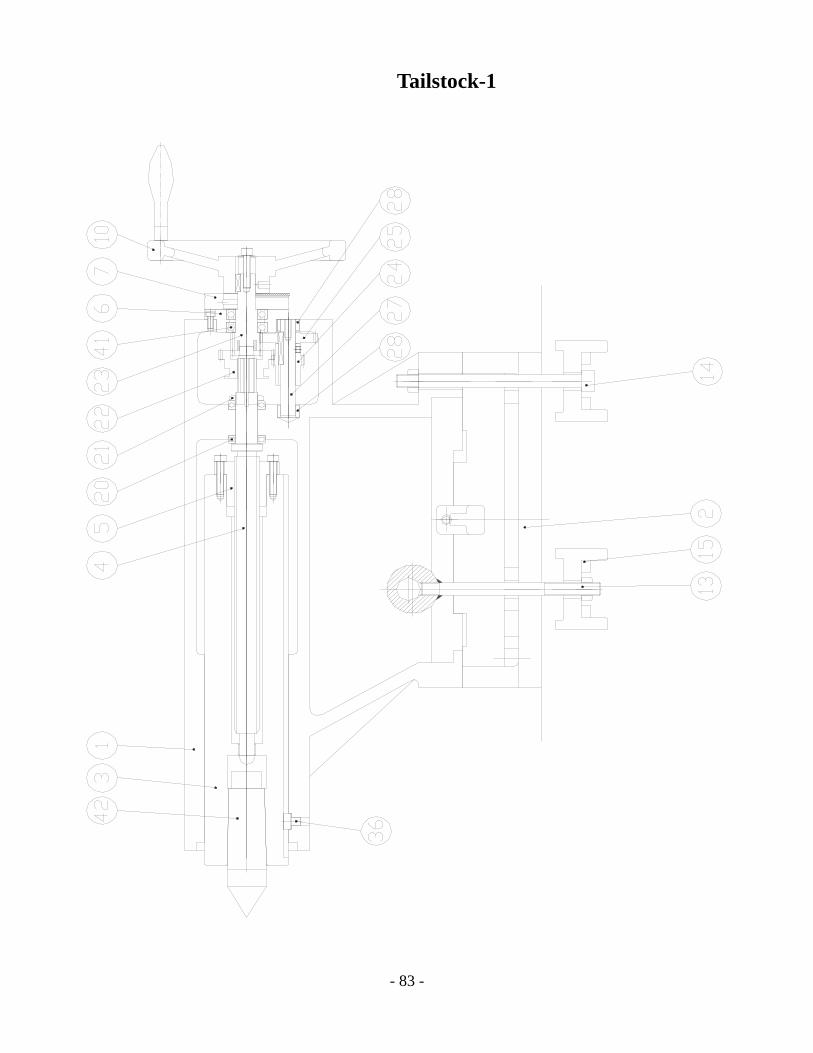
Tailstock-1

- 84 -
Tailstock-2

- 85 -
Tailstock Item Part No. Description Qty.
1 W26T-001 TAILSTOCK BODY 1 2 W26T-002 TAILSTOCK BASE 1 3 26NCT-003 QUILL 1 4 26NCT-004 SCREW 1 5 26NCT-005 BRASS NUT 1 6 26T-006 GEAR BOX COVER 1 7 26T-007 SCALE RING 1 8 W26T-008 LOCKING LEVER 1 9 W26T-009 LOCKING BLOT 1
10 26T-010 HAND WHEEL 1 11 W26T-011 LOCKING BAR 1 12 26T-012 FIXED LEVER 1 13 26T-013 CLAMPING BOLT 1 14 W26T-014 SCREW 1 15 W26T-003 FIXED BASE 2 16 26T-016 CAP SCREW 1 17 26T-017 LOCKING BOSS 1 18 26T-018 LEVER 1 19 W26B-001 BED 1 20 51105# BERING 2 21 M25 SET NUT 1 22 26T-022 SHIFT GEAR 1 23 26T-023 SHAFT 1 24 26T-024 GEAR 1 25 26T-025 GEAR 1 26 26T-026 ROCKING ARM 1 27 26T-027 QUILL 1 28 26T-028 SLEEVE 1 29 26T-029 POST 1 30 26T-030 ROCKING ARM 1 31 26T-031A TEETH SHAFT 1 32 26T-032 ROCKING ARM 1 33 26T-034 SHIFT SHAFT 1 34 26T-035 SHIFT RACK 1 35 26T-036 T-KEY 1 36 26T-037 WIPER COVER 1 37 26NCT-036 FORK 1

- 86 -
Tailstock Item Part No. Description Qty. 38 26T-038 WIPER COVER 1 39 26T-039 WIPER 1 40 26T-040 WIPER 1 41 6005# BEARING 2 42 M.T.#5 CENTER 1 43 26H-091-2 SHIFT LEVER 1
- 87 -
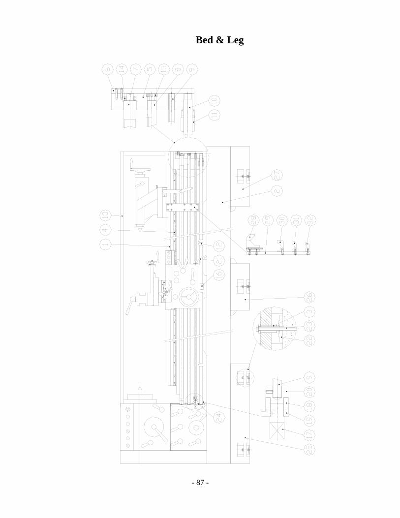
Bed & Leg

- 88 -
Bed & Leg
Item Part No. Description Qty. 1 W26B-001 BED BODY 1 2 METAL PLATE 1 3 26B-003 SCREW 8 4 26B-025 RACK 1 5 26B-005 SCREW FRAME 1 6 26B-006 COVER 1 7 26B-007 LEAD SCREW 1 8 26B-008 FEED LEVER 1 9 26B-009 SWITCH LEVER 1 10 26B-010 STOP LEVER 1 11 26B-011 SLEEVE 1 12 26B-012 DOG 1 13 26B-067-4 REAR SPLASH GUARD 1 14 6205# BEARING 1 15 6203# BEARING 1 16 26B-058 BRACKET 1 17 26B-017-1 SHAFT 1 18 26B-018 FRAME 2 19 26B-019 BRACKET 2 20 26B-020 RACK 1 21 26B-021 SWITCH HANDLE 1 22 26B-084 LINER 8 23 M12XP1.75 CAP SCREW 8 24 26B-071 SIDE COVER 1 25 W26B-002A LEG 1 26 W26B-002B LEG 1 27 W26B-002C LEG 1 28 26B-059 MOVING BLOCK 1 29 26B-060 BRACKET BLOCK 1 30 26B-062 BRACKET 1 31 26B-063 BRACKET 1 32 26B-064 BRACKET 1
Item Part No. Description Qty.

- 89 -
Micro Stopper
1 26B-083 LOCKING PLATE 1 2 26B-085 BODY 1 3 26B-086 SHAFT 1 4 26B-087 PAD 1 5 26B-088(M、I) SCALE RING 1 6 26B-089 SHAFT 1 7 M10X55L CAP SCREW 2

- 90 -
Turret Type 4-Step Stopper
Item Part No. Description Qty. 1 26B-081 BODY 1 2 26B-082 TURNING RING 1 3 26B-083 LOCKING PLATE 1 4 M10X80L CAP SCREW 1 5 M10X70L CAP SCREW 1

- 91 -
Steady Rest

- 92 -
Steady Rest
Item Part No. Description Qty. 1 W26C-001 BODY 1 2 26C-002 SOCKET 3 3 26C-003 HANDLE 3 4 26C-004 SCREW 3 5 26C-005 SHAFT 3 6 26C-006 BEARING REST 3 7 26C-007 ROLLER 3 8 26C-008 SHAFT 3 9 26C-009 SHAFT 2
10 26C-010 ROD 1 11 26C-011 HANDLE 1
- 93 -
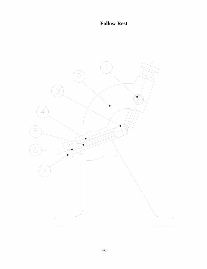
Follow Rest

- 94 -
Follow Rest
Item Part No. Description Qty. 1 38001 SET SCREW 1 2 38002 BODY 1 3 38003 CLAW 1 4 38004 CLAW SHAFT 1 5 38005 ADJUSTMENT SCREW 1 6 SPRING PIN 1 7 38006 HANDLE BOSS 1