unit-i: 1. 2. 3. v. 4. 5. 6. 7. ii. 8. 9. 10. 11. 12. iv ... · 9. draw sectional front view and...
TRANSCRIPT

Unit-I:
1. Sketch any Two of the following;
i. Full section and Half – section with an example.
ii. Representation of bearings, splined shaft and tension spring.
iii. Aligned and unidirectional system of dimensioning.
2. Sketch the following with proper dimensioning:
i. Any one type of foundation bolt.
ii. Union Joint for pipes.
3. Show the conventional representation of the following materials
i. Wood
ii. Lead
iii. Straight Knurling
iv. Internal Screw Threads
v. Bearings on machines
4. Describe the drawing sheet designation and their sizes as per ISO-A series.
5. Sketch the conventional representation of the various materials.
6. Draw the front view, Top view, and Side views from left side and right side Figure 3.42, page
number 63,Machine Drawing by K L Narayana (2)
7. Explain the following terms with symbols.
i. First angle projection
ii. Third angle projection
8. List out the various principles to be followed while dimensioning a drawing.
9. Describe the different types of sectional views with suitable examples.
10. Sketch the conventional representation of the different engineering materials.
11. Sketch the conventional representation of different machine components.
12. Give the shape identification symbols for the following
i. Diameter
ii. Radius
iii. Square
iv. Spherical radius
13. Draw the front view, Top view, and Side views from left side and right side Figure 3.42, page
number 63, Machine Drawing by K L Narayana (2)
14. Draw (i) the sectional view from front ii.) the view from above ii.i) the view from left of a fork
shown in Fig 4.16, page number 75, Machine Drawing by KL Narayana(2)
15. List out and draw the standard thicknesses of lines that are used in machine drawing.
16. Enumerate different types of drawing instruments
Unit-II
1. Draw High button head, button head and cone head type of rivets with a dia of 18 mm.
2. Draw at least four types of set screws.
3. Show different types of key heads at least four.
4. Draw sectional front view and top view of the triple riveted butt joint with double straps(zig zag type)
with dia of Rivet as 18 mm.
5. Indicate left-handed and right handed threads both internal and external.
6. Draw sectional front view and side view of the Cotter Joint with a gib of 40sQ.
7. Draw sectional front view and top view of the double riveted but joint with double strap (chain type)
with dia of rivet as 20 mm.
8. Draw the triple start square threads with D as 30 mm.

9. Draw sectional front view and side view of Cotter joint with socket and spigot ends taking d=30 mm.
10. Draw sectional front view and top view of double riveted, zig zag joint with dia of rivet as 10 mm.
11. Draw two views of locking the nut with set screw if D= 30mm.
12. Draw sectional front view and side view of the Cotter Joint with a gib of 40 square.
13. Draw sectional front view and top view of double riveted, zig zag joint with dia of rivet as 10 mm.
14. Draw two views of hexagonal headed bolt and nut and square headed bolt alongwith nut. (D=30mm).
15. Draw the sectional front view and top view of the double riveted double strap zig zag butt joint with
dia of the rivet as 14 mm.
16. Draw at least four types of thread profiles taking pitch as 20 mm.
17. Draw sectional front view and side view of Cotter joint with socket and spigot ends taking d=30 mm.
18. Draw pan head, Flush counter sunk head and Truss head type of rivets with a dia of 16 mm.
19. Answer any Two of the following by drawing proportionate diagrams:
i. Single riveted, double strap butt joint for plates of 12 mm thickness with cover plate thickness
of 10 mm
ii.. Muff coupling to connect two shafts of 50mm diameter.
iii. Foot step bearing for a shaft of 75 mm diameter.
20. Answer any Two of the following by drawing proportionate diagrams
i. Triple riveted single strap zig-zag butt joint to connect two plates of 12mm thick.
ii.. Flange coupling to connect to shafts of 20 mm diameter.
iii. Journal bearing for a shaft of 30 mm diameter.
Unit- III
1. The details of the stuffing box for a vertical steam engine are given in figure.10. Assemble the parts
and draw:
i. Front view right half in section. (Nov 03)
ii. Half sectional side view.
iii. Top view.
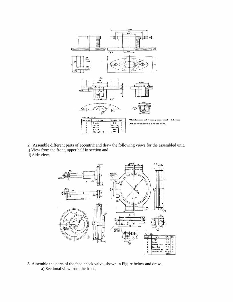
2. Assemble different parts of eccentric and draw the following views for the assembled unit.
i) View from the front, upper half in section and
ii) Side view.
3. Assemble the parts of the feed check valve, shown in Figure below and draw,
a) Sectional view from the front,

b) View from the right
c) View from above.
4. Assemble all parts of the screw jack shown in below and draw
a) Front view- right half in section
b) Top view
c) Right side view

5. Draw Assembly of universal coupling given bellow.

6. Draw Assembly of plumber block given bellow.