unit 4 - lecture 9 - rf cavities · rf cativties: basic concepts fields and voltages are complex...
TRANSCRIPT
US Particle Accelerator School
Unit 4 - Lecture 9
RF-accelerators:
RF-cavities
William A. Barletta
Director, United States Particle Accelerator School
Dept. of Physics, MIT

US Particle Accelerator School
RF-cativties for acceleration
Microtron Synchrotron
Linac

US Particle Accelerator School
S-band (~3 GHz) RF linac
RF-input
RF-cavities

US Particle Accelerator School
RF cativties: Basic concepts
Fields and voltages are complex quantities.
For standing wave structures use phasor representation
For cavity driven externally, phase of the voltage is
= t +
For electrons v c; therefore z = zo+ct
˜ V = Vei t where V = ˜ V
Zo is the reference plane
At t = 0 particle receives maximum voltage gain

US Particle Accelerator School
Basic principles and concepts
Superposition
Energy conservation
Orthogonality (of cavity modes)
Causality

US Particle Accelerator School
Basic principles:Reciprocity & superposition
If you can kick the beam, the beam can kick you
==>
Total cavity voltage = Vgenerator+ Vbeam-induced
Fields in cavity = Egenerator+ Ebeam-induced

US Particle Accelerator School
Basic principles: Energy conservation
Total energy in the particles and the cavity is conserved
Beam loading
Ui Uf
Wc
Wc = Ui - Uf

US Particle Accelerator School
Basics: Orthogonality of normal modes
Each mode in the cavity can be treated independently in
computing fields induced by a charge crossing the cavity.
The total stored energy is equals the sum of the energies in
the separate modes.
The total field is the phasor sum of all the individual mode
fields at any instant.
US Particle Accelerator School
Basic principles: Causality
There can be no disturbance ahead of a charge moving at
the velocity of light.
In a mode analysis of the growth of the beam-induced
field, the field must vanish ahead of the moving charge for
each mode.
US Particle Accelerator School
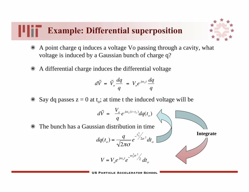
Example: Differential superposition
A point charge q induces a voltage Vo passing through a cavity, what
voltage is induced by a Gaussian bunch of charge q?
A differential charge induces the differential voltage
Say dq passes z = 0 at to; at time t the induced voltage will be
The bunch has a Gaussian distribution in time
d ˜ V = ˜ V odq
q = Voe
j ot dq
q
d ˜ V = Vo
qe j o ( t to )dq(to)
dq(to) =q
2e
to2
2 2dto
Integrate
V =Voej ote
o2 2
2 dto

US Particle Accelerator School
Basic components of an RF cavity
Outer region: Large, single turn Inductor
Central region: Large plate Capacitor
Beam (Load) current
I
B
EDisplacement current
Wall current
a
RdPower feed from rf - generator
US Particle Accelerator School
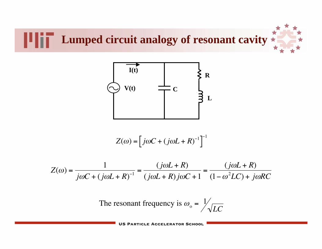
Lumped circuit analogy of resonant cavity
V(t)
I(t)
C
L
R
Z( ) = j C + ( j L + R) 1[ ]1
The resonant frequency is o = 1LC
Z( ) =1
j C + ( j L + R) 1=
( j L + R)
( j L + R) j C +1=
( j L + R)
(1 2LC) + j RC
US Particle Accelerator School
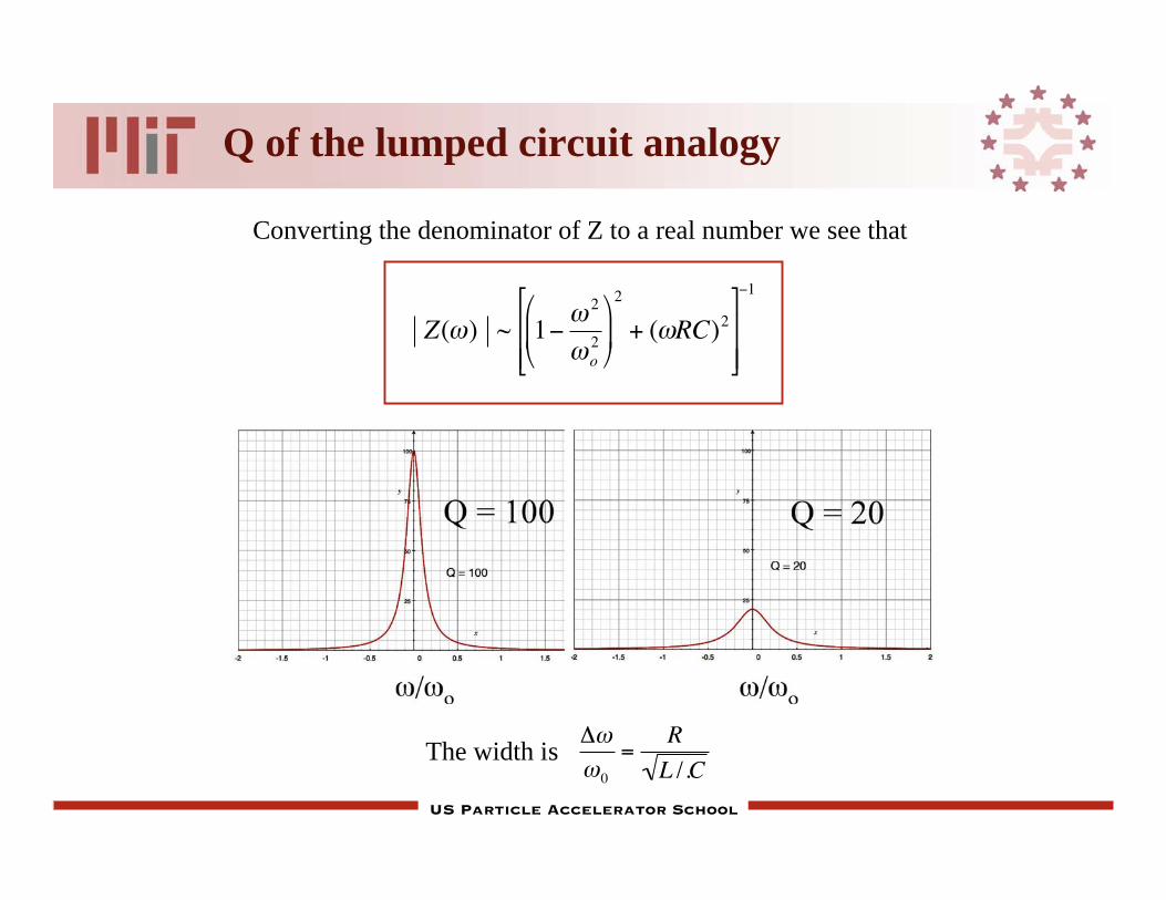
Q of the lumped circuit analogy
The width is0
=R
L /.C
Z( ) ~ 12
o2
2
+ ( RC)2
1
Converting the denominator of Z to a real number we see that

US Particle Accelerator School
More basics from circuits - Q
Q = o o Energy stored
Time average power loss
= 2 o Energy stored
Energy per cycle
E =
1
2L IoIo
*and
P = i2(t) R = 1
2IoIo
*Rsurface
Q = L
CR
= o
1
US Particle Accelerator School
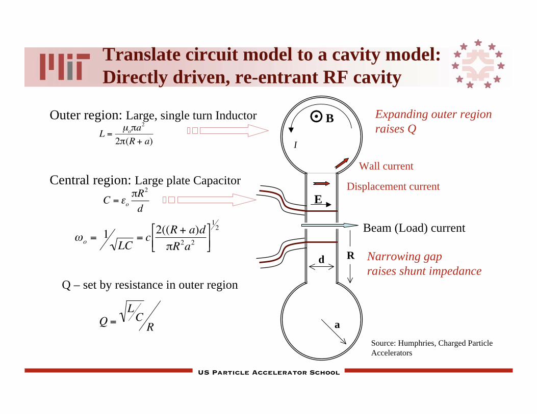
Translate circuit model to a cavity model:
Directly driven, re-entrant RF cavity
Outer region: Large, single turn Inductor
Central region: Large plate Capacitor
Beam (Load) current
I
B
EDisplacement current
Wall current
a
Rd
L =μo a
2
2 (R + a)
C = o
R2
d
o = 1LC
= c2((R + a)d
R2a2
12
Q – set by resistance in outer region
Q =LCR
Expanding outer region
raises Q
Narrowing gap
raises shunt impedance
Source: Humphries, Charged Particle
Accelerators

US Particle Accelerator School
Properties of the RF pillbox cavity
We want lowest mode: with only Ez & B
Maxwell’s equations are:
and
Take derivatives
==>
1
r rrB( ) =
1
c 2 tEz r
Ez =tB
t
1
r rrB( )
= t
B
r+B
r
=1
c 2
2Ezt 2
r
Ezr
=r
B
t
2Ezr 2
+1
r
Ezr
=1
c 2
2Ezt 2
d
Ez
b
B
walls =
US Particle Accelerator School
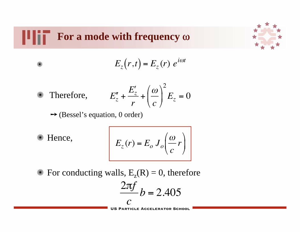
For a mode with frequency
Therefore,
(Bessel’s equation, 0 order)
Hence,
For conducting walls, Ez(R) = 0, therefore
Ez r, t( ) = Ez (r) ei t
E z + E z
r+
c
2
Ez = 0
Ez (r) = Eo Jo cr
2 f
cb = 2.405

US Particle Accelerator School
E-fields & equivalent circuit: Ton1o mode
Ez
B
Rela
tive inte
nsity
r/R
T010
CL
US Particle Accelerator School
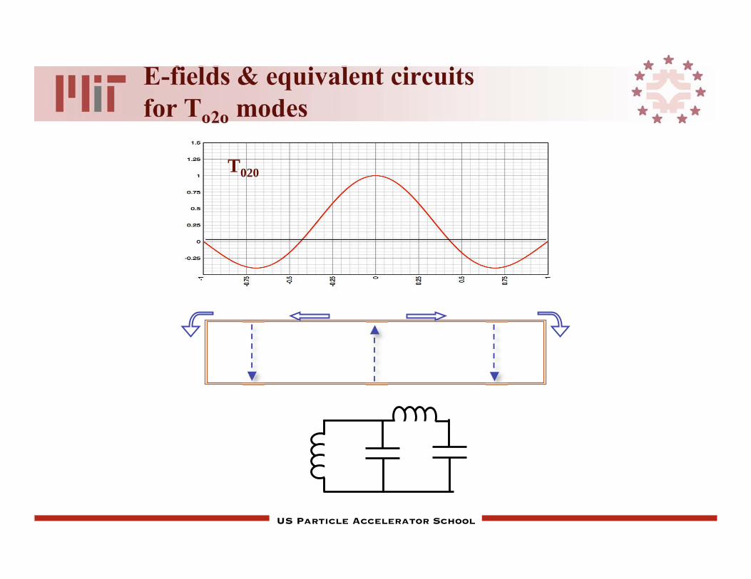
E-fields & equivalent circuits
for To2o modes
T020
US Particle Accelerator School
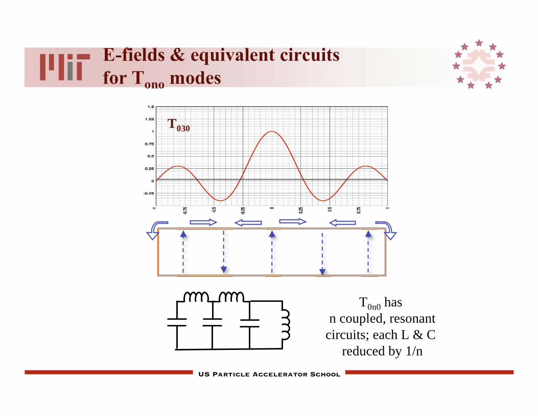
E-fields & equivalent circuits
for Tono modes
T030
T0n0 has
n coupled, resonant
circuits; each L & C
reduced by 1/n
US Particle Accelerator School
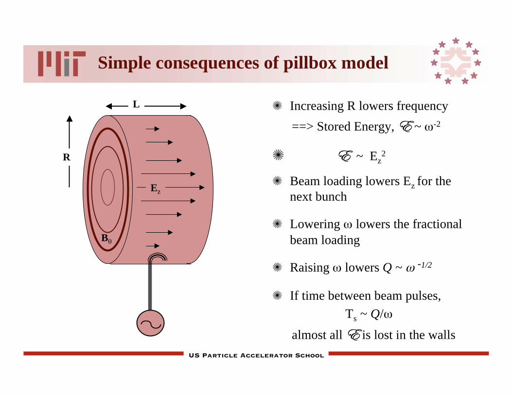
Simple consequences of pillbox model
L
Ez
R
B
Increasing R lowers frequency
==> Stored Energy, E ~ -2
E ~ Ez2
Beam loading lowers Ez for the
next bunch
Lowering lowers the fractional
beam loading
Raising lowers Q ~ -1/2
If time between beam pulses,
Ts ~ Q/
almost all E is lost in the walls
US Particle Accelerator School
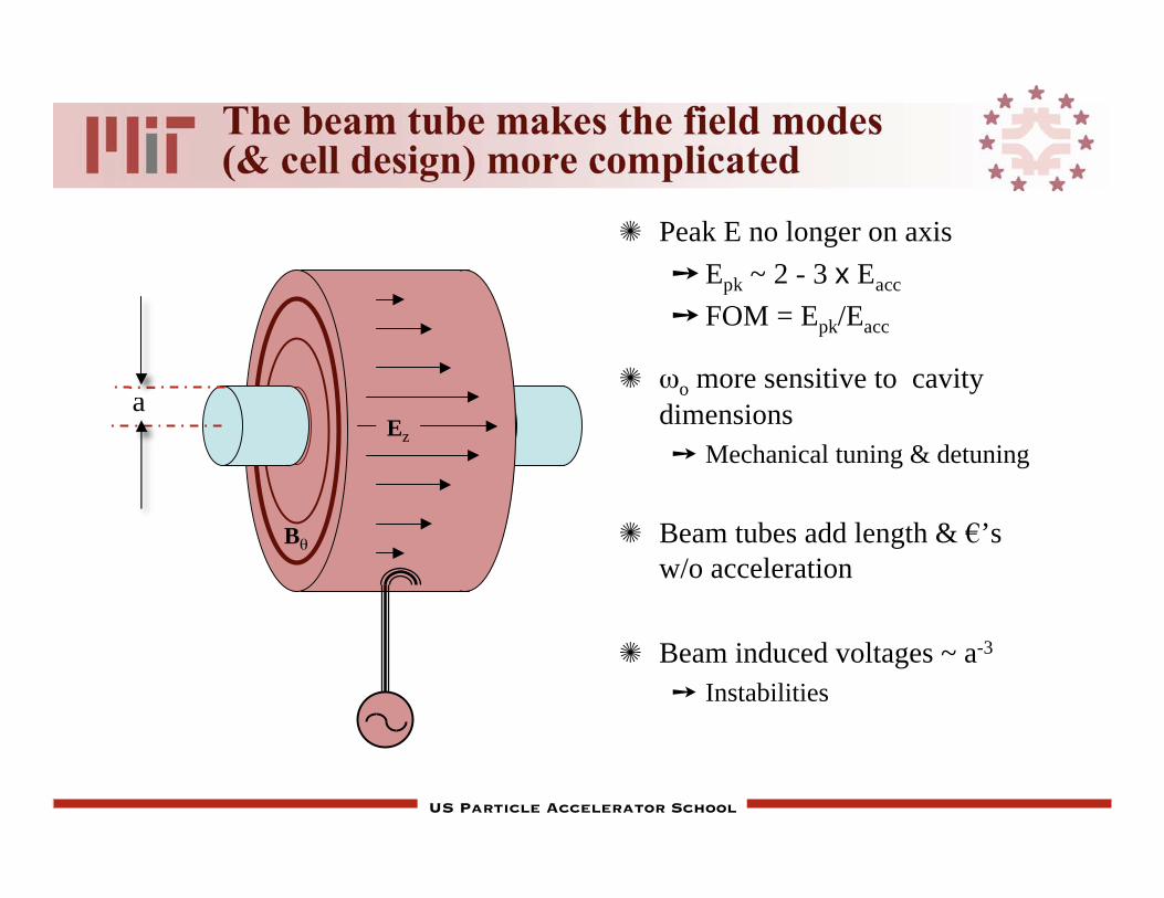
The beam tube makes the field modes(& cell design) more complicated
Ez
B
Peak E no longer on axis
Epk ~ 2 - 3 x Eacc
FOM = Epk/Eacc
o more sensitive to cavity
dimensions
Mechanical tuning & detuning
Beam tubes add length & ’s
w/o acceleration
Beam induced voltages ~ a-3
Instabilities
a

US Particle Accelerator School
Cavity figures of merit

US Particle Accelerator School
Make the linac with a
series of pillbox cavities
Power the cavities so that Ez(z,t) = Ez(z)ei t

US Particle Accelerator School
Figure of Merit: Accelerating voltage
The voltage varies during time that bunch takes to cross gap
reduction of the peak voltage by (transt time factor)
=sin 2( )
2 where = d
c
2
TrfFor maximum acceleration ==> = 2/
d
Vt
Epk
US Particle Accelerator School
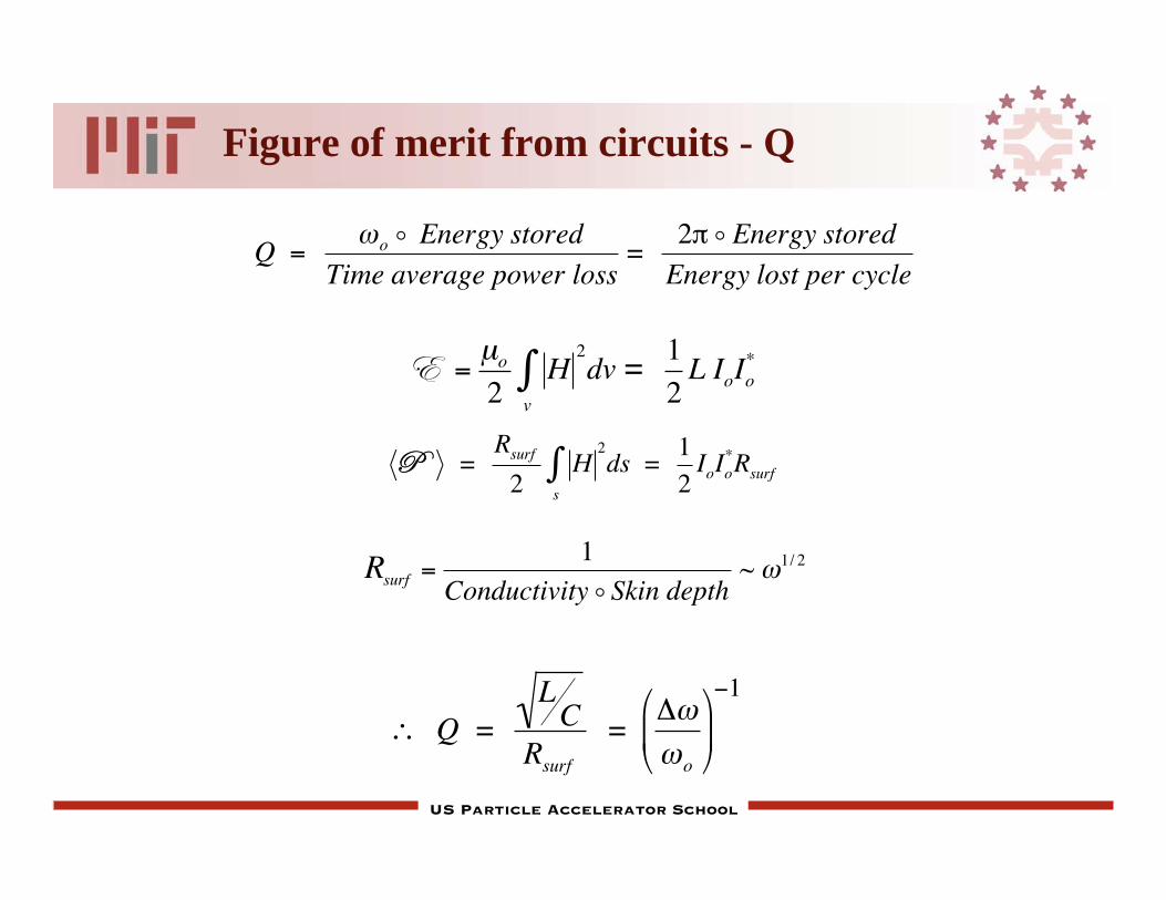
Figure of merit from circuits - Q
E =μo2
Hv
2dv =
1
2L IoIo
*
P = Rsurf
2H
s
2ds =
1
2IoIo
*Rsurf
Q = LC
Rsurf
= o
1
Q = o o Energy stored
Time average power loss=
2 o Energy stored
Energy lost per cycle
Rsurf =1
Conductivity o Skin depth~ 1/ 2

US Particle Accelerator School
Measuring the energy stored in the cavity
allows us to measure
We have computed the field in the fundamental mode
To measure Q we excite the cavity and measure the E field
as a function of time
Energy lost per half cycle = U Q
Note: energy can be stored in the higher order modes that
deflect the beam
U = dz0
ddr2 r
0
b Eo2
2
J1
2(2.405r /b)
= b2d Eo2 /2( ) J1
2(2.405)

US Particle Accelerator School
Keeping energy out of higher order modes
d/b
b/c
0 1 2 3 4
TM020
TM010
TE011
TE111Source bandwidth
(green)
Dependence of mode frequency
on cavity geometry
Choose cavity dimensions to stay far from crossovers
10
5
1
TE111 mode
End view
Side view

US Particle Accelerator School
Figure of merit for accelerating cavity:power to produce the accelerating field
Resistive input (shunt) impedance at relates power dissipated in walls to
accelerating voltage
Linac literature commonly defines “shunt impedance” without the “2”
Typical values 25 - 50 M
Rin = V 2(t)
P =
Vo2
2P = Q L
C
Rin = Vo
2
P ~
1
Rsurf
US Particle Accelerator School
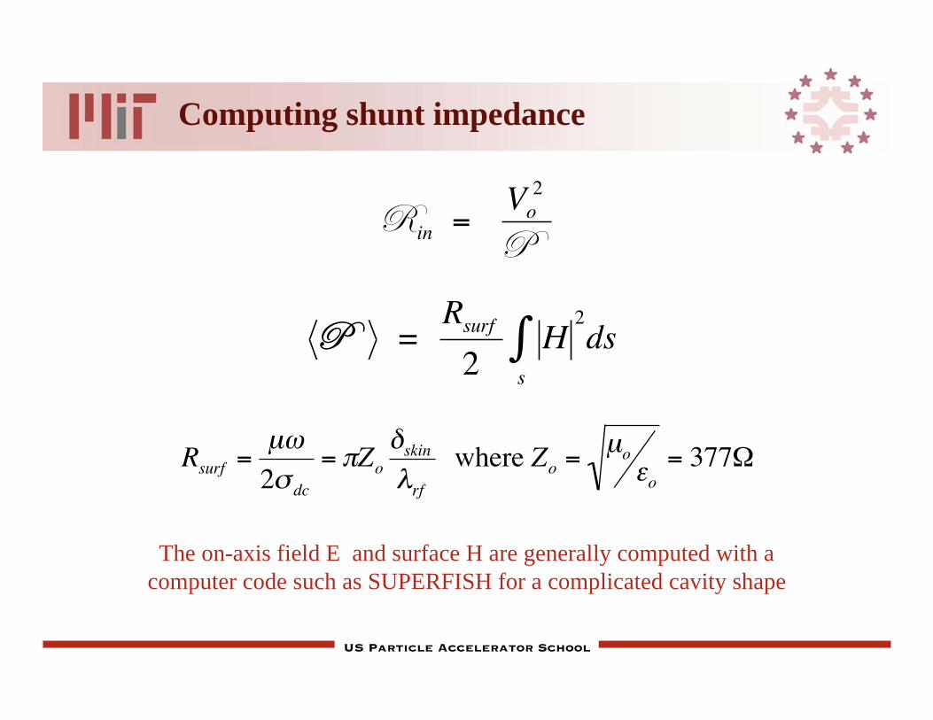
Computing shunt impedance
P = Rsurf
2H
s
2ds
Rin = Vo
2
P
Rsurf =μ
2 dc
= Zoskin
rf
where Zo =μo
o= 377
The on-axis field E and surface H are generally computed with a
computer code such as SUPERFISH for a complicated cavity shape

US Particle Accelerator School
Compute the voltage gain correctly
The voltage gain seen by the beam can computed in the co-moving frame,
or we can use the transit-time factor, & compute V at fixed time
Vo2
= E(z)dzz1
z2

US Particle Accelerator School
Exercise: Pillbox array
Derive the Q and Rsh for the pillbox cavity as a function of
the dimensions of the cavity and the frequency of the
fundamental mode

US Particle Accelerator School

US Particle Accelerator School
Z( ) =1
j C + ( j L + R) 1=
( j L + R)( j L + R) j C +1
=( j L + R)
(1 2LC) + j RC
=( j L + R)
12
o2
2
+ j RC
=
( j L + R) 12
o2
j RC
12
o2
2
+ RC( )2
=
j L 12
o2
R2C
+ R 1
2
o2
+
2
o2 R
12
o2
2
+ RC( )2
j L 12
o2
R2C
+ R
12
o2
2
+ RC( )2
=1
12
o2
2
+ RC( )2
R + j L 12
o2
R2C
Z =1
12
o2
2
+ RC( )2
R2 + 2 L 12
o2
R2C
2
1/ 2
Note on previous slide