unit 15: sizing of stand-alone pv systems based on the ... · (as in 100% sure) that a stand-alone...
TRANSCRIPT

Unit 15: Sizing of stand-alone PV systems based on the “worst month” method
Author: Alberto Escudero-Pascual . IT+46. V0.9. Based on orginal work from ISF.(cc) Creative Commons Attribution Share Alike 3.0
Table of contents1. About this document ...........................................................................................................................2
1.1 Degree of difficulty.........................................................................................................................2
1.2 information about the icons............................................................................................................2
1.3 Acknowledgments and intellectual propertyz..................................................................................2
2. Introduction..........................................................................................................................................3
3. General data........................................................................................................................................4
4. Electrical characteristics of system components..................................................................................5
4.1 Panels............................................................................................................................................5
4.2 Batteries.........................................................................................................................................5
4.3 Regulator........................................................................................................................................6
4.4 Equipment or loads........................................................................................................................6
5. Two previous decisions........................................................................................................................6
6. Procedure of calculation......................................................................................................................7
6.1 Orientation of the panels................................................................................................................8
6.1.1 Azimuth.....................................................................................................................................8
6.1.2 Inclination..................................................................................................................................9
6.2 Required current in the worst month..............................................................................................9
6.3 Final calculations..........................................................................................................................10
6.3.1 Number panels........................................................................................................................10
6.3.2 Capacity of the battery or accumulator....................................................................................11
6.4 Regulator......................................................................................................................................11
6.5 DC/AC Inverter.............................................................................................................................12
6.6 Cables..........................................................................................................................................12
7. Intellectual Property Rights ...............................................................................................................16
8. Stipulations of intellectual property for this unit..................................................................................16
Pág: 1 TRICALCAR | www.wilac.net/tricalcar – Versión: February 2008

1. About this document This material is part of the course package created for TRICALCAR project. For information on
TRICALCAR, please consult the introductory module or, www.wilac.net/tricalcar/. This material was
originally developed inSpanish for the TRICALCAR project.
1.1 Degree of difficulty
The degree of difficulty of this unit is “basic”.
1.2 information about the icons
In this unit you will find 5 types of icons whose meaning is described below:
Central concept Important practice
recommended
Exercise Intellectual
property
Intellectual
property
1.3 Acknowledgments and intellectual propertyz
In 1998, the organization Engineering without Borders (Spanish Federation) published the first version
of a handbook titled "Manual de Energía Solar Fotovoltaica y Cooperación al Desarrollo". The
handbook was written and published by members of the NGO and experts of the Institute of Energy
Solar of the Polytechnical University of Madrid. By curiosities of life, none of the members of the
editorial team kept the document in electronic format and more editions were never made. They have
passed almost ten years from that very first edition and this document is an effort to rescue and to
extend the handbook.
As part of this rescue operation I want to thank to the coordinators of the first original edition and my
mentors in my years at University: Miguel Ángel Eguido Aguilera, Mercedes Montero Bartolomé y Julio
Amador. This new work is licensed under Creative Commons Attribution Share Alike. We hope that
this material becomes a new departure point for new editions including new contributions by the
community.
Pág: 2 TRICALCAR | www.wilac.net/tricalcar – Version: february 2008

2. Introduction
The objective of unit is to be able to choose and “size” the elements of a stand-alone photovoltaic
installation. The system sizing implies (at least) to decide the number and type of solar panels required
to capture the solar energy, the capacity of the battery that will store the energy for the days of little sun,
and to be able also to determine the required characteristics of the rest of the elements that integrate
the system (regulator, converter, cables, etc). During the system sizing you will decide the number of
days of autonomy of your system, a measure of the reliability of your installation.
The system sizing calculations are important because the size of elements of the installation must be
balanced and respect certain proportions. If we install more solar panels to produce more energy, the
batteries should be dimensioned to be able store it, if the bank of batteries is too small and the loads
are not using the energy, the energy needs to be thrown away. A regulator of a smaller amperage than
needed, or one single cable conductor with an insufficient section can be cause of failure or fire and to
render the installation unusable. The size of the elements is specially important if you are thinking to
install the batteries and panels at the top of communication towers.
You should never forget the limitations of the photovoltaic energy to produce
and store electrical energy, a light bulb that is left on by negligence during days
can be fatal. The "fuel" of the photovoltaic systems, the solar radiation, have a
difficult to predict behaviour. In fact, it is never possible to be absolutely sure
(as in 100% sure) that a stand-alone system is going to be able to provide the
necessary energy at any moment.
Solar systems are designed for a certain consumption and if the user exceeds the planned limits
constantly the provision of energy will fail.
The design method that we propose consists of considering the energy requirements, and based on
them to calculate a system that works the maximum amount of time so it is the most trustworthy
(reliable) as possible. Logically, whatever more panels and batteries installed, more energy will be able
to be collected and to be stored. This increase of reliability of the installation will also have an increase
in cost.
There are photovoltaic installations, as the provision of energy to telecommunication equipment that is
part of the backbone of a radio network, in which the reliability factor is more important that the cost. In
a client installation a low cost is going to be a determining factor. To find a balance between cost and
reliability is not a easy task, and whatever decision you take, the really important thing is that you are
able to determine what it is expected from your design and at what price.
Pág: 3 TRICALCAR | www.wilac.net/tricalcar – Version: february 2008

Diverse procedures of calculation exist to ensure certain reliability at the minimum cost, but they
require access to a lot of statistical data of solar radiation that is normally not available in many
regions.
We propose a much more simple method, known as the "method of the worst
month", that consists in calculating the dimensions of the stand-alone system
so it can work in the month in which the demand of energy is greater with
respect to the solar energy available.
It is the worst month, as the month with the bigger ratio of demanded energy versus available energy.
The method is widely used as it is simple and provides satisfactory results.
In this method the reliability is taken into consideration by fixing the maximum
number of days that the system can work without receiving solar radiation and
all the consumption is made solely at the expense of the energy stored in the
battery. This number of days is known as the maximum number of days of
autonomy (N). In brief N, is related to the number of consecutive cloudy days
when the panels do not collect practically energy.
At the time of choosing N, it is necessary to consider several factors: the climatology of the place, the
type of installation or its economic and social relevance (illumination of houses, hospital, factory, radio
link, etc). Remember that the greater it is the N, the greater the investment. It is also important to
evaluate all possible logistical costs of equipment replacement, it is not the same to change a
discharged battery from an installation in the middle of a city that from the top a telecommunication
tower that is several hours or days of walking distance.
Fixing the value of N, it is not an easy tasks as there are many factors
involved, and many of them cannot be evaluated easily. Institution and
experience play an important role in this part of the system sizing. A few tips
can be provided here, for critical telecommunications equipment a good
number is N = 5, whereas for low cost client equipment it is possible to be
reduced the autonomy to N = 3.
At the end of this guide, we have included several tables that will facilitate the collection of required data
and the sizing of the system. The next sections will explain in detail what information you need to collect
and estimate and how to use the method of the “worst month”.
3. General data
• Latitude of the place . With positive sign in the North hemisphere and negative in the South.
• Data of solar radiation . For the method of the "worst month" it is enough to know twelve
values, one for every month. The twelve numbers are the monthly average values of daily
Pág: 4 TRICALCAR | www.wilac.net/tricalcar – Version: february 2008

global irradiation on horizontal plane (Gdm (0), in kWh/m 2 × day). The monthly value results
from the sum of the values of global irradiation of every day of the month divided by the number
of days of the month.
If you have the data in Jules (J), you can apply the following conversion (1 J = 2,78 × 10 -7 kWh).
The irradiation data Gdm (0) of many places of the world is gathered in tables and data bases. It is also
recommendable to check for that information in a weather station close to your implementation site but
do not be surprise if you can not find the data in electronic format. A good idea is to ask to companies
that install photovoltaic systems in the region, there experience can be of great value.
Another alternative is to use the information of the number of sun hours per
day (without clouds). The number of sun hours is available in tourist areas;
just have in mind that you will need to convert that information to Gdm(0)
values. The method to convert from sun-hours to solar radiation is outside of
the scope of this unit.
Another important concept that you should not confuse with "sun hours" is the one of number of
"peak sun hours".
The number of peak sun hours has nothing to do with the number of hours
without clouds, but the amount of daily irradiation. A day of 5 hours of sun
without clouds does not necessary has those hours when the sun is at its
zenit.
A peak sun hour is a normalized value of solar radiation of 1000 W/m² at 25 C. So when we refer to 5
hours of peak sun hours, we are talking of a daily solar radiation of 5000 W/m².
4. Electrical characteristics of system components
The electrical characteristics of the components of your system needs to be provided by the
manufacturer. It is advisable to take your our own measures to notice possible deviations with respect
to the nominal values. Unfortunately, deviation from promised values can be big and quality assurance
of solar panels and batteries is another complex task.
These are the monimum values that you need to gather before starting your system sizing:
4.1 Panels
You need to know the voltage VPmax and the intensity/current IPmax in the point of maximum power in
standard conditions.
4.2 Batteries
Pág: 5 TRICALCAR | www.wilac.net/tricalcar – Version: february 2008

Nominal capacity (for 100 hours discharge) CNBat operational voltage VNBat
and, either the maximum deep of discharge DoDmax or useful capacity CUBat.
You also need to know the type of battery that you plan to use, sealed lead-
acid, gel, AGM, modified traction etc.
The type of battery is important when deciding the cut-off set points in the regulator.
4.3 Regulator
Nominal tension VNReg, and the maximum current that can operate ImaxReg.
DC/AC Converter/Inverter
If you are going to use any you need to know the nominal voltage VNConv , instantaneous Power PIConv
and Performance at 70% of maximum load h 70 .
4.4 Equipment or loads
For each of them it is necessary to know the nominal voltage VNC and the nominal power of operation
PC .
In order to know the total energy that our installation is going to consume, it is also very important to
consider the average time of use of each load, if it is daily, weekly, monthly or annual, and to consider
any changes in the usage that might exist (seasonal, training or school periods, etc)
5. Two previous decisions
Apart from the electrical characteristics of the components and loads, it is necessary to have two more
pieces of information before being able to do a system sizing. This two decisions are related to system
autonomy and operational voltage.
• N, number of days of autonomy
You need to agree in value for N that takes care of the meteorological conditions, the type of installation
and overall costs. It is very difficult to give you a concrete value of N for each part of the planet and
installation but in the next table there are some recommended values. Take this values as a rough
approximation, and consult with a experience designer to reach a final decision.
Winter Domestic installation Critical installation
very cloudy 5 10
variables 4 8
sunny 3 6
Table 1: Estimation of the number of days of autonomy
Pág: 6 TRICALCAR | www.wilac.net/tricalcar – Version: february 2008

• VN, nominal voltage of the installation
The components of your system need to be chosen to operate at a certain nominal voltage VN.
Normally, the voltage is 12 or 24 Volts for the small systems and if the total
power of consumption surpasses 3 kW, the voltage must be 48 or 120 V.
The election of the value of the nominal voltage of the installation is not absolutely arbitrary and
depends on, to a great extent, the availability of equipment in the market.
• If the equipment allows it, try to fix the nominal voltage to 12 or 24 V. Some wireless
communications boards as Mikrotik's routerboards accept a wide range of input voltage
(between 11 and 60 V DC).
• If you need to power several types of equipment that work at different nominal voltages, make a
calculation what is the tension that minimizes the overall power consumption including the
looses for power conversion in DC/DC and DC/AC converters.
6. Procedure of calculation
Before entering into detail, let us have a global idea of how the overall sizing process of calculation
takes place. There are three main steps that need to be followed:
1º Solar Energy Available (the offer)
Based on statistical data of solar radiation, and the orientation and the optimal
inclination of the solar panels we calculate the solar energy available. The
estimation of solar energy available is done in monthly intervals, reducing the
statistical data to 12 values. This estimation is a good compromise between
precision and simplicity.
2º Electrical Energy Required (the demand)
We study the power consumption characteristics of the equipment chosen and
their estimated usage. We calculate the electrical energy required per monthly
basis. The electrical energy demand is calculated taking into consideration the
expected fluctuations of usage. Factors to take into consideration are the
variations between winter-summer, rainy period-dry season, school-vacation
period etc. The result is 12 values of energy demand.
Pág: 7 TRICALCAR | www.wilac.net/tricalcar – Version: february 2008

3º System sizing (the result)
With the data from the “worst month”, the one in which the relation between the
solar demanded energy and the energy available is greater, we calculate:
• The current that the array of panels needs to provide and therefore, the
number of panels.
• The necessary energy storage capacity and, therefore, the number of
batteries.
• The electrical characteristics of the regulator.
• The length and the necessary sections of cables for the electrical
connections.
6.1 Orientation of the panels
Unless the sky is totally covered, most of the energy coming from the sun arrives in straight line. The
solar module will capture more energy if it is “facing” the sun, perpendicular to the straight line between
the position of the installation and the sun. “Unfortunately”, the sun is not steady and we need to find a
optimal position for our panels.
The orientation of the panels is determined by two angles, the azimuth a
(angle that measures the deviation with respect to the south, in the north
hemisphere, and with respect to the north, in the South hemisphere) and the
inclination or elevation ß (angle formed by the surface of the module and the
horizontal plane).
6.1.1 Azimuth
You should have the module turned towards the terrestrial equator (facing south in the north
hemisphere, and north in the south) so that during the day the panel catches the biggest amount of
possible radiation (a = 0).
It is very important that the panels or part of them are under shade!. Study the
elements that surround to array of panels (trees, buildings, walls, etc), and
possible shades of a row of panels can on the others.
It is acceptable to turn the panels ±20º towards the east or the west if needed (a = ±20º).
Pág: 8 TRICALCAR | www.wilac.net/tricalcar – Version: february 2008

6.1.2 Inclination
Once you have fixed the azimuth, the parameter that is key in our calculations is
the inclination of the panel, that we will express as the angle beta (ß).
The maximum height that reaches the sun every day varies according to the stations, having its
maximum in the day of the summer solstice and its minimum in the winter solstice. The best of the
situations will be when the panels tracks this variation but this is not possible for cost reasons. In some
scenarios you can consider two fixed inclinations, one position for the months of summer and another
for the months of winter, but in this case you need to have special support structures and only makes
sense if there is a considerable increase of the consumption during the summer.
In installations with telecommunications equipment it is normal to have the panels with a fixed
inclination. In most of the scenarios the demand of energy of the system is constant during the year and
therefore the "worst month" will always be the one with less isolation.
The value of ß should maximize the ratio between offer and the demand of energy.
This is translated, depending on the different scenarios, in:
• For installations with constant or similar consumptions throughout the year,
it is preferable to optimize the installation to the capture the maximum
radiation during "the winter" months. You should use the absolute value of
the latitude of the place (angle F) increased in 10° (ß = | F | + 10 °).
• For installations with inferior consumptions in winter the value of the latitude
of the place can be used as the solar panel inclination. The system is
optimized for the months of spring and autumn (ß = | F |).
• For installations that are only used during summer, you should use the
absolute value of the latitude of the place (angle F) decreased in 10°(ß = | F
| - 10°).
It is also recommended that the inclination of the panel should never be less than 15° to avoid the
accumulation of dust and/or humidity. In repeating telecommunication stations in areas where exists
snow and ice it is very important to protect the panels and to incline them an angle superior to 65°.
6.2 Required current in the worst month
For every month you need to calculate the quotient I m.
I m is the maximum daily current that a array of panels operating at nominal
voltage of VN needs to provide in a day with a irradiation of Gdm in a month "m"
and with an inclination of panels ß.
Pág: 9 TRICALCAR | www.wilac.net/tricalcar – Version: february 2008

The Im(WORST MONTH) will be the greater one of the Im, and the system sizing is based on the data
of that worth month.
The calculations of Gdm(ß) for a certain place can be made based on Gdm(0)
using conversion tables and or computer software as PVSYST or PVSOL.
Due to the losses in the regulator, batteries and that the panels do not always work in the point of
maximum power a correction is applied and the required current ImMAX is calculated as:
ImMAX = 1,21 Im (WORST MONTH)
Once you have determined what is the worst month, and what is the value of ImMAX and the total
energy that you require ETOTAL(WORST MONTH) you can proceed to the final calculations.
6.3 Final calculations
6.3.1 Number panels
The panels are designed to be part of a modular array, being possible to combine them in series,
parallel or a mixed form. By combining the panels we can obtain the desired voltage and current.
When the panels are connected in series , the total voltage is equal to the sum
of the individual voltages of each module while maintaining the same intensity;
when connecting in parallel, they currents are summed together, remaining the
same the voltage. It is important, to avoid any electrical deviations when
connecting panels, ensuring that the array is composed of same type of
panels and characteristics.
In general, you should try to acquire panels with VPmax a bit bigger than the nominal voltage of the
system (12, 24 or 48 V). Remember that you need your panel to provide a few volts more than the
nominal voltage of the battery to get it charged. If it is not possible to find a single panel that satisfies
your requirements, you need to connect several panels in series to reach your desired voltage. The
number of panels in series Nps is the next superior integer to the quotient between the nominal voltage
of the system and the voltage of the panel.
Nps = VN / VPmax
In order to calculate the number of panels in parallel (Npp), you need to divide the ImMAX by the current
of the panel Ipmax in the point of maximum power and take the next superior integer as Npp
Npp = ImMAX / IPmax
Pág: 10 TRICALCAR | www.wilac.net/tricalcar – Version: february 2008

The total number of panels is the result of multiplying the number of panels in one series (to fix voltage)
by the number of series in parallel (to fix current) Nps x Npp.
6.3.2 Capacity of the battery or accumulator
The battery determines the overall voltage of your the system and needs to have enough a capacity to
provide energy to the loads when there is not enough solar radiation.
One important warning: in photovoltaic systems, the association in parallel is
not recommendable. The degradation of the battery individual cells (2 V) does
not take place in a homogeneous form, different cells will support more fatigue
than others.
To estimate the capacity of our battery, we first calculate the required energy capacity of our system
(necessary capacity, CNec). The necessary capacity depends on the energy available in the “worst
month” and the desired number of days of autonomy (N) that we decided previously.
CNEC (Ah)= ETOTAL(WORST MONTH) (Wh)/VN(V). N
The nominal capacity of the battery CNOM needs to be bigger than the CNEC as we can not fully
discharge a battery. To calculate the size of the battery we need to take into consideration what is the
maximum deep of discharge (DoD) that the battery allows:
CNOM(Ah) = CNEC(Ah)/DoDMAX
In order to calculate the number of batteries in series (Nbs), we divide the nominal voltage of our
installation (VN) between the nominal voltage of the battery (VNBat):
Nbs = VN / VNBat
6.4 Regulator
One other important warning: never use a regulator in parallel, use always
regulators in series.
For security reasons, a regulator needs to be able to operate with a current ImaxReg at least 20%
greater than the maximum intensity that is provided by the array of panels:
ImaxReg = 1,2. Npp . IPMax
Pág: 11 TRICALCAR | www.wilac.net/tricalcar – Version: february 2008

6.5 DC/AC Inverter
The total energy needed for the AC equipment it is calculated including all the looses that introduces
the DC/AC converter or inverter. When choosing an inverter, it is good to know that the performance of
the inverters is not constant with the power. An inverter has better performance when operating close to
its nominal power. Using an inverter of 1500 Watts to power a load of 25 Watts is extremely inefficient.
In order to avoid this waste of energy it is important to consider not the peak power of all your
equipments but the peak power of the equipments that are expected to work simultaneously.
6.6 Cables
Once you know the numbers panels, batteries and type of regulators and inverters that you want to use,
it is necessary to calculate the length and the section of the cables needed to connect the different
elements of the photovoltaic system.
The length depends on the location of your the installation. A general rule is to
try to minimize the length of the cables between the regulator and the panels
and batteries. By having short cables we can minimize the voltage drop, the
section of the cables and its cost.
The section is chosen based on the length of cables and the current that
circulates.
The goal is to minimize voltage drops. In order to calculate the section S of the cable it is necessary to
know:
• The maximum current IMC that is going to circulate in the cable. In the case of the panel-battery
subsystem, it is the ImMAX calculated for every month. In the battery-loads subsystem depends
on the way that the loads are connected.
• The voltage drop (Va-Vb) that we consider permissible in the cable. The voltage drop that
results of adding all possible individual drops is expressed as a percent of the nominal
tension of the installation. Typical maximum values are:
Section of the PV System Voltage Drop (% of VN)
Panel Array-Battery 1%
Battery-converter 1%
Main line 3%
Main Line (illumination) 3%
Main Line (equipment) 5%
• Typical acceptable voltage drops in cables
The section of the cable comes determined by the Ohm Law:
Pág: 12 TRICALCAR | www.wilac.net/tricalcar – Version: february 2008
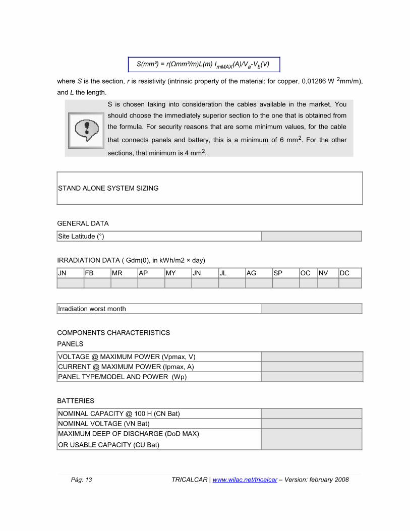
S(mm²) = r(Ωmm²/m)L(m) ImMAX(A)/Va-Vb(V)
where S is the section, r is resistivity (intrinsic property of the material: for copper, 0,01286 W 2mm/m),
and L the length.
S is chosen taking into consideration the cables available in the market. You
should choose the immediately superior section to the one that is obtained from
the formula. For security reasons that are some minimum values, for the cable
that connects panels and battery, this is a minimum of 6 mm2. For the other
sections, that minimum is 4 mm2.
STAND ALONE SYSTEM SIZING
GENERAL DATA
Site Latitude (°)
IRRADIATION DATA ( Gdm(0), in kWh/m2 × day)
JN FB MR AP MY JN JL AG SP OC NV DC
Irradiation worst month
COMPONENTS CHARACTERISTICS
PANELS
VOLTAGE @ MAXIMUM POWER (Vpmax, V)
CURRENT @ MAXIMUM POWER (Ipmax, A)
PANEL TYPE/MODEL AND POWER (Wp)
BATTERIES
NOMINAL CAPACITY @ 100 H (CN Bat)
NOMINAL VOLTAGE (VN Bat)
MAXIMUM DEEP OF DISCHARGE (DoD MAX)
OR USABLE CAPACITY (CU Bat)
Pág: 13 TRICALCAR | www.wilac.net/tricalcar – Version: february 2008

REGULATOR
NOMINAL VOLTAGE (VN Reg)
MAXIMUM CURRENT (Imax Reg)
DC/AC INVERTER (IF NEEDED)
NOMINAL VOLTAGE (VN Conv)
INSTANTENOUS POWER (PI Conv)
PERFORMANCE @ 70% LOAD
REALIABILITY AND SYSTEM OPERATIONAL VOLTAGE
DAYS OF AUTONOMY (N)
NOMINAL VOLTAGE (VN Equip)
LOADS
ESTIMATED ENERGY CONSUMED BY THE LOADS (DC)
MONTH WITH BIGGER CONSUMPTION:
EQUIPMENT
DESCRIPTION
NUMBER OF
UNITS
(1)
NOMIMAL
POWER
(2)
USAGE
HOURS-DAY
(3)
ENERGY
(Wh/día)
E=(1) x (2) x (3)
ETOTAL DC (before any converter) =
ESTIMATED ENERGY CONSUMED BY THE LOADS (AC)
MONTH WITH BIGGER CONSUMPTION:
EQUIPMENT
DESCRIPTION
NUMBER OF
UNITS
(1)
NOMIMAL
POWER
(2)
USAGE
HOURS-DAY
(3)
ENERGY
(Wh/día)
E=(1) x (2) x (3)
Pág: 14 TRICALCAR | www.wilac.net/tricalcar – Version: february 2008

ETOTAL AC (before any converter) =
ETOTAL AC (after converter) = ETOTAL AC / h (70%)
ELECTION OF WORST MONTH
PLACE:
LATITUDE:
NOMINAL VOLTAGE OF THE INSTALATION VN(V):
JN FB MR AP MY JN JL AG SP OC NV DC
INCLINATION ß
Gdm (ß) (Kwh/m2 × day)
ETOTAL (DC) (Wh/day)
ETOTAL (AC) (Wh/day)
ETOTAL (AC + DC)=
Im (A) = ETOTAL (Wh/day) ×
1kW/m2/ (Gdm(ß) x VN)
WORST MONTH (SUMMARY)
ImMAX (A)
ImMAX (A) = 1' 21 x Im
ETOTAL (AC + DC)
FINAL CALCULATIONS
PANELS
PANELS SERIES (NPS) NPS = VN / VPmax =
PANELS PARALLEL (NPP) NPP = ImMAX / IPmax =
TOTAL NUMBER OF PANELS NTOT = NPS x NPP =
BATTERY
NECCESARY CAPACITY (CNEC) CNEC =(ETOTAL(WORST MONTH)
Pág: 15 TRICALCAR | www.wilac.net/tricalcar – Version: february 2008

PEOR))/VN).NAut =
NOMINAL CAPACITY (CNOM) CNOM = CNEC / DoDmax =
NUMBER OF BATTERIES IN
SERIES (NBS) NBS = VN / VNBat =
CABLES
PANELES –
BATTERIES BATTERIES - CONVERTER MAIN LINE
TENSION DROP
(Va-Vb)
SECTION
(r. L.ImMAX/(Va-Vb))
7. Intellectual Property Rights
The materials developed for the TRICALCAR project utilise a short version of the MMTK – Multimedia
Training Kit, and have been created to be used and freely shared by instructors connected to new
technologies for human development.
All materials are available under one of the Creative Commons licences.
<http://creativecommons.org/>.
These licenses have been created with the objective of promoting and facilitating the sharing of
materials while retaining some rights over intellectual property of the authors.
Due to the fact that TRICALCAR organisations using MMTK have different needs and work in different
contexts, there is not a single license that covers all the contents. For a more detailed account of the
terms and conditions under which you can use and distribute each unit, please verify the declaration of
intellectual property specified for each one of them.
8. Stipulations of intellectual property for this unit
This unit is available under the terms of the Attribution-Noncommercial-Share Alike 3.0 Unported
license:
• Attribution.You must attribute the work in the manner specified by the author or licensor (but
not in any way that suggests that they endorse you or your use of the work).
• Noncommercial. You may not use this work for commercial purposes.
Pág: 16 TRICALCAR | www.wilac.net/tricalcar – Version: february 2008

• Share Alike. If you alter, transform, or build upon this work, you may distribute the resulting
work only under the same or similar license to this one.
Pág: 17 TRICALCAR | www.wilac.net/tricalcar – Version: february 2008