understanding virtual router and virtual systems v1
TRANSCRIPT

Understanding Virtual Router and Virtual Systems PAN-‐OS 6.0 Humair Ali Professional Services

Content
Table of Contents
VIRTUAL ROUTER .................................................................................................................................. 5 CONNECTED ............................................................................................................................................. 8 STATIC ROUTING .................................................................................................................................... 9 OSPF ......................................................................................................................................................... 11 BGP ........................................................................................................................................................... 17 IMPORT RULE ........................................................................................................................................................... 21 REDISTRIBUTE RULE .............................................................................................................................................. 28 IBGP .......................................................................................................................................................................... 41 ROUTE REFLECTOR ................................................................................................................................................. 45
HIGH AVAILABILITY ........................................................................................................................... 49 ACTIVE-‐PASSIVE ...................................................................................................................................................... 49

Purpose of this Document The purpose of this document is to explain how Virtual Router and Virtual system works and some example on they need to be configured. It is not a complete guide for every scenario but is aimed at giving pointers on how to achieve some of Routing or Virtual System configurations This document is mostly focus on examples where the Palo Alto Networks Firewall is configured in Layer 3 mode and not for Layer 2 or Vwire . The Inter-‐vsys is inherent as most Virtual Routers are in their own Virtual Systems, so most of the Routing that we will see are setup across Multi-‐VSYS
Lab Setup All the commands and output shown in this document is based on the PA-4020 unless specifically said otherwise PANOS 6.0.10 PA-4020 in HA Active/Passive Physical Setup
1 3
2 4
5
6
7
8
PA-4020
POWER
FANS
ALARM
STATUS
HA PWR 1
USB 1 / 2
17 19 21 23
18 20 22 24 HA2
HA1
TEMP PWR 2
MGT
CONSOLE
9 11
10 12
13
14
15
16
PA-‐4020
Cisco SG500 Switch
Eth1/2Eth1/1
Vsys1
Vsys2
1 3
2 4
PA-500
POWER
FAN
ALARM
STATUS
HA
TEMP
MGT CONSOLE USB
5 7
6 8
PA-‐500
Eth1/3 – 10.193.56.x/24
INTERNET
Default GW 10.193.56.1Ubuntu Desktop PA-‐VM-‐300
Default GW to PA-‐500 10.193.56.2
10.193.58.x/24
.200
.2
.22
10.193.57.x/24
.2.200
.2
EBGP


Virtual Routers in Multi-VSYS environment
Virtual Router The firewall uses virtual routers to obtain routes to other subnets by manually defining a route (static routes) or through participation in Layer 3 routing protocols (dynamic routes). All routes learned are first place in the routing information base (RIB) The best route obtained through these protocol are used to populate the firewall’s Forwarding information base (FIB). When a packet is destined for a different subnet, the Virtual Router obtains the best route from this FIB and forwards the packet to the next hop router defined in the table. You can configure the virtual router to participate with dynamic routing protocols (BGP, OSPF, or RIP) as well as adding static routes. You can also create multiple virtual routers (VR), each maintaining a separate set of routes that are not shared between virtual routers, enabling you to configure different routing behaviors for different interfaces. 1 VSYS can have all multiple VR’s as well as multiple VSYS can share the same VR Each Layer 3 interface, loopback interface, and VLAN interface defined on the firewall must be associated with a virtual router. While each interface can belong to only one virtual router, multiple routing protocols and static routes can be configured for a virtual router. The firewall uses Ethernet switching to reach other devices on the same IP subnet. The common command in Virtual Router will start with the following:
Ø show routing route Ø show routing fib Ø show routing protocol xxx Ø Show routing route type xxxx
Show routing route is essentially the RIB of the Firewall
è Routing Table in Management Plane
Show routing FIB is essentially the FIB of the Firewall è Best routes selected and installed in the DataPlane , and is the routes use for actual
packet forwarding

In my lab , the output on PA-‐4020
> show routing route
Ø Show routing fib
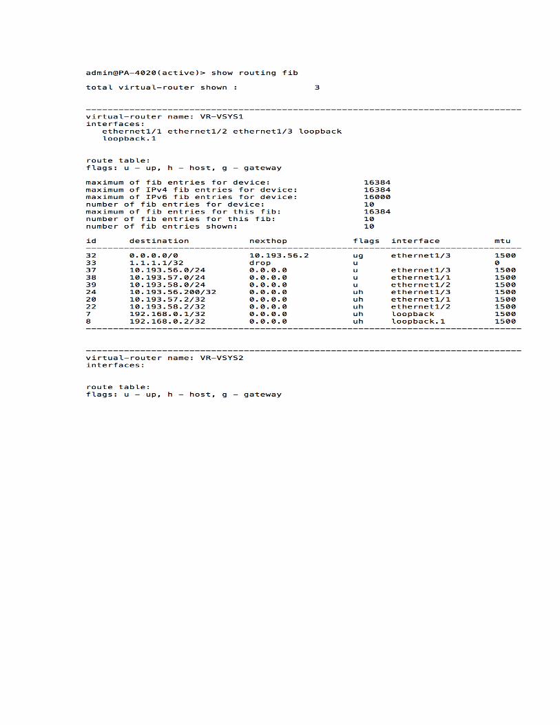

If you look at the “Show routing route”, it will display the RIB table from the Firewall All the routes that are “active” are marked with an “A” in the flags column. If you look at the “show routing fib” , all the route entries in it are the one marked with A in “ show routing route” and only those ones.
CONNECTED Connected routes are IP Subnet belonging to the Firewall interfaces itself. All interfaces configured in the Firewall will belong to this category. Connected are the most commonly routes used for Redistribution in other Routing Protocols with Static routes.

**Important** any /32 interface (including Loopback) configured on the Firewall are not considered “Connected” but Host, and therefore cannot be redistributed.
As you can see from above screenshot, Host are not define in the Redistribution Profiles and cannot therefore be redistributed into OSPF. The workaround is to “advertise” those interface define the IP address /32 in “Export rules” (see ospf section)
STATIC ROUTING To configure a static route

NextHop: As you would expect in any static route , you have to define a directly connected next hop for reachability to external network **Important** Palo Alto Device does not support recursive lookups, so all next hop IP must be directly connected.

If a non-directly connected IP has to be define, then a second static route has to be define to advise how to reach that non-directly connected Next hop IP. Next-VR: to forward traffic to a destination that is not in the local VR but another VR Used often when dealing with Multiple VSYS scenario, where each VSYS has its own VR. Discard: often use when needing to blackhole traffic, this is the equivalent next hop “Null” in other Vendors. **Important*, in 5.x, 6.0 and 6.1 , Discard route were not to be redistributed to OSPF because they don’t’ have a valid next hop. This behavior has been modified, where now you can redistribute Next-Hop Discard in OSPF from PAN-OS 6.1.4 (backported to 6.0.10 and above as well). Discard routes can be redistributed in BGP in any version without issues. None: often use for NAT and/or Global Protect Tunnel interface
NAT: When doing NAT to a subnet/IP address that is not directly connected ( meaning not part of any Firewall Interface subnets), it allows to install the route so that IP Lookup during NAT evaluation can occur successfully for the NAT translation to be completed. Global Protect: When doing Global Protect, it is often required to have a static route pointing to the GP Subnet allocated with Interface “tunnel.x” and use the next hop “none” . This is allows the GP subnet to be installed in the Routing table so FW know where to forward the GP user packet back to, and it knows from the interface configure that it is reachable via “tunnel.x” interface (and doesn’t need next ip for that hence the none).
OSPF OSPF is a Link State Routing protocol based on AREA’s to segment a customer network. The segmentation is based on: 1. Backbone network (aka Area 0) 2. Area Border router (ABR- Firewall/Routers having at least an interface in backbone and another in a different area),

3. Internal ( Firewall/routers only belong to one area ) OSPF uses IP multicast to send link-state updates. This ensures less processing on routers that are not listening to OSPF packets. Also, updates are only sent in case routing changes occur instead of periodically. This ensures a better use of bandwidth. OSPF has better convergence than RIP. This is because routing changes are propagated instantaneously and not periodically. OSPF allows for a logical definition of networks where routers can be divided into areas. This limits the explosion of link state updates over the whole network. This also provides a mechanism for aggregating routes and cutting down on the unnecessary propagation of subnet information. OSPF allows for routing authentication by using different methods of password authentication. OSPF allows for the transfer and tagging of external routes injected into an Autonomous System. In 7.0, with the addition of ECMP feature , OSPF will allow for better load balancing. The minimum basic item to configure to get OSPF up and running: -Define Router ID -Define Area ID -Define Area Type (normal by default) -Define interface to be part of the OSPF -Define Link Type (Broadcast by Default)

After setting up the neighborship


As you can see in the above output, all /32 address are seen as Host (via the flags H), The 1.1.1.1/32 is a static route (Discard) redistributed into OSPF (we are on 6.0.10), yet we are not seeing our loopback ip 192.168.0.2/32 in the table. This means any loopback required in OSPF cannot be redistributed, The workaround is to “Export” the /32 IP so it can be “advertise” in OSPF.

From the above note, since Loopbacks cannot be redistributed into OSPF, It leads to the conclusion that you cannot have OSPF running between different VSYS/VR instances, however within a single VSYS/VR , OSPF can be established. The workaround is to use a Physical cable across 2 physical interfaces assigned in their respective VR in the device or use a 3rd party switching/routing equipment in between the 2 VR’s.

BGP BGP is a Distance vector Protocol based on AS-PATH , It is compose of “Attributes” , some are transitive (mean are kept across AS-PATH) , some are non transitive (mean only relevant in the local AS) Any BGP session between 2 different AS are called External BGP (EBGP) and any BGP session within one AS are called Internal BGP (IBGP) The rule is all IBGP (in the same AS) neighbors must be full mesh to avoid routing loop, The only way to overcome this rule is to create Route Reflector or Confederations. Here we will cover only Route Reflector as Confederation are not as commonly used in the market. In general, BGP is the most flexible routing protocol for inter-VR/VSYS routing , it gives you much more granularity in controlling routes than any other protocols. However Palo Alto Networks preferred method for Inter-VR/VSYS communication remains via Static Routes. To configure BGP with the default settings,
Graceful Restart is enable by default

The default for the PEER Group configuration is below
When doing EBGP,

In my opinion the key thing that should “usually” be change straight away by the Admin on the BGP configuration is to change the : Import Next Hop: from “Original” to “ Use Peer” Export Next Hop: from “Resolve” to “ Use Self” This is always to be double check depending on the customer topology and routing as in some case, the changes of Next Hop may not be required, but in my opinion it should be set as “Use PEER” and “Use Self” by default The reason for this By default when a route is advertised to an Ebgp outside of the AS, the router will make sure that the next-hop attribute reflects its original IP address (basically preserving the announcer IP address). As a result when a route is advertised to an Ibgp speaker and sourced into the BGP as-group, all Ibgp routers will have for next-hop the ip address of the Ebgp neighbor. But what happen if the Ebgp speaker is not reachable? What happen if the IBGP peer does not know how to get to the EBGP speaker announcing the route (not IP reachability)?. To prevent this, we can make sure that a route advertised to an Ibgp router; echoes the IP address of the router sourcing that route into the AS to the Ibgp neighbors; and not the IP address of the Ebgp speaker which originally advertised this route.

As you can see, a lot of the information are left by default and those timers should work in most case for your customer. If a faster failure detection is required for BGP, you can set the BGP to be more aggressive by lowering “Keep Alive “ and Hold time” respectively to 10 and 30 (instead of default 30 and 90 sec)

Note the row highlight in RED “MULTI-HOP” By default , the number of Hop is 0, which is usually a TTL of 1 , TTL of 1 mean it will establish BGP only with a directly connected peer (it will not do more than 1 hop). In other to have more than 1 hop you can increase this value to 2 (recommended for EBGP) or 255. 2 or more Hop (or TTL if you prefer) can be useful when doing BGP Neighborship (whether EBGP or IBGP) between the PA loopback and the peering router Loopback . The above information should be enough to setup most basic/regular BGP For any advance BGP, you will need to start playing with the features specs.
Import Rule So let’s create an import rules from Static to BGP (redistribute 2 static route into BGP) in VR-VSYS1 and we will then advertise them to VR-VSYS2

I am importing the 2 subnet 10.194.56.0/24 and 10.193.58.0/24 and I want to tag them with the Community Attribute of 65002:1111 and replacing the default Local Pref from 100 to value of 200

So now let’ s check our BGP Neighborship (here on VR-VSYS2 , but same for VR-VSYS1)

Cool, see that even without manipulating too many options, BGP Neighborship comes up , so the default values are good enough to get us up and running. (the import policy is just to have routes in BGP as this is a lab environment, and see if they are advertise to the BGP peer, they are not mandatory to setup for simple BGP Neighborship) Let us check the BGP routes learned
No Routes ??!! Anybody figured out why yet? If you go back to the 1st screenshot in the BGP section
The “Install Route” option is not ticked (it is unticked by default) If I enable the tick next to “Install Routes” and commit

Voila !!! ;-) You see that the receiving end (VR-VSYS2 BGP is receiving BGP routes) from VR_VSYS1 IP 10.193.57.2 Let us check the BGP route details to ensure how Attributes (Local Pref, Communities) are also correctly advertise So In VR-VSYS1, which is the one who own the routes and will be advertising to VR-VSYS2, I have highlight the key info relative to 10.193.56.0/24 route specifically but that applies to all the other routes

In VR-VSYS2
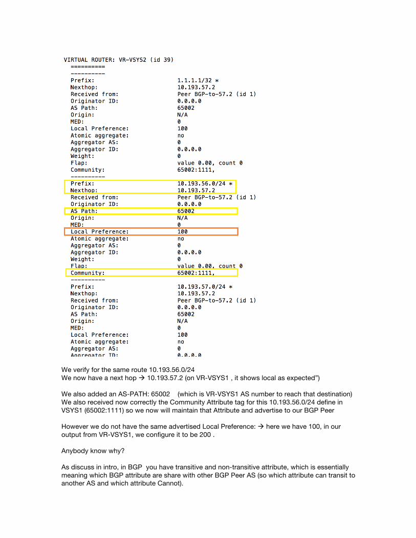
We verify for the same route 10.193.56.0/24 We now have a next hop à 10.193.57.2 (on VR-VSYS1 , it shows local as expected”) We also added an AS-PATH: 65002 (which is VR-VSYS1 AS number to reach that destination) We also received now correctly the Community Attribute tag for this 10.193.56.0/24 define in VSYS1 (65002:1111) so we now will maintain that Attribute and advertise to our BGP Peer However we do not have the same advertised Local Preference: à here we have 100, in our output from VR-VSYS1, we configure it to be 200 . Anybody know why? As discuss in intro, in BGP you have transitive and non-transitive attribute, which is essentially meaning which BGP attribute are share with other BGP Peer AS (so which attribute can transit to another AS and which attribute Cannot).

In intro, we specify that Local Pref is a powerful attribute but is non-transitive and has only Local significance, meaning it only is relevant within its own AS (here only within VR-VSYS1 AS) So all in all, it looks like we are doing ok so far.
Redistribute Rule Redistribute Rule allows to “redistribute” route from one protocols into another protocol While we saw some test previously on Communities, Let’s see the maximum community can be added when redistributing route into BGP

From the above Screenshot, we can see that the “Add” button is greyed out after 10 communities added That tell us we cannot have more than 10 Communities redistributed to a route. Again Palo Alto is a firewall and not a router and 10 should be more enough for 99.9% of cases. On VR-VSYS1, we do see correctly the 10 Communities

Let’s verify on VR-VSYS2, and Yes we do receive all 10 Communities

Now this shows that when redistributing from one protocol into BGP, we can add up to 10 Communities. But when Advertising from one BGP peer on the PA FW to another BGP Peer, we can only append 1 community

I have tried different ways to append additional Communities but we just cannot. So the main recommendation should all communities tagging required should be done by an upstream/downstream router so can forward it to the next hop. So What if we try to have 2 export rules to see if we can append 2 communities list, Lets change the setup so that the same prefix (let’s try with 10.193.56.0/24) be use in 2 different export profile Creating 2 export rule (in below order) in VR-‐VSYS1 to same neighbour for the same prefix (10.193.56.0/24) to be advertise to VR-‐VSYS2 10.193.57.120 , each with different communities (purposefully change to different communities to validate the redistribution) export rule 1 : 10.193.56.0/24 with community 65010:9876 export rule 2 : 10.193.56.0/24 with community 65010:5432

This is the Export rule for community 65002:9876

This is the Export rule for community 65002:5432
In RED, the advertise communities from the Export Rules,

in GREEN the advertised communities from the Redistribution rules, since we are appending we should see both the Export rules communities and the Communities from the Redistribution Rules.
Notice we don’t see the 2nd export rule communities 65002:5432 If I swap the rule order to make Export rule community 65002:9876 below 65002:5432

Same behavior, we now see the top order export rule with community 65002:5432 but not the bottom export rule 65002:9876 So the Export rule is matching the first Export rule but not processing the bottom one, Let’s see if this is because each are Export rule based on same attributes (Communities) by Pre-pending AS-PATH which is a different Attribute. From the current output, we only have 1 AS-PATH
Let’s create our AS-PATH prepending policy

We have place it at the bottom in the Rule order , below the 2 Community export rules We should now expect the AS 65002 to be prepending 5 times

In the output, it looks the export rule did not work as we still only 65002 once. But we still see the Community 65002:5432 in the community list (who is at the top of the order in Export rules) If we place the AS-Path –Prepending export rule at the order (so the 2 Community export rules are below)

Now we see the AS-Path Prepending (first rule in the order list) work, but we lost all the other Export List communities (there is no 65002:9876 nor 65002:5432 community anymore in “community” ). If we create a 4th filter, this time with a different prefix (10.193.58.0/24) with AS-PATH PREPENDING 5

Here our prefix 10.193.58.0/24 Export rules is at the bottom And when we verify

Now using a different subnet in the match criteria, we are having the AS-PATH prepending happening. That confirms the Export rules do a first match action and stop processing any following export rules.
IBGP So now that we have tested BGP successfully, let’s try and setup iBGP between the 2 VSYS. We currently have EBGP between VR-VSYS1 and VR-VSYS2, We will now create a 3rd VSYS with its own VR called “VR-VSYS3” and have IBGP between the 2 . We create another loopback for VR-VSYS3 with IP 192.168.0.4/32 The config on VR-VSYS2 is still the same (loopback IP is 192.168.0.3/32) and AS is 65120 So VR-VSYS2 config looks like

Created a new Peer Group with BGP type as “IBGP”
As you can see , we define Peer AS 65120 , which is the same as our Local AS , This is normal as IBGP is BGP peering between 2 neighbour within the same AS. So the expected behavior is all the EBGP routes learn from VR-VSYS1 by VR-VSYS2 , VR-VSYS2 will then advertise all those routes to VR-VSYS3 (as they are IBGP neighbor, they both advertise to each other all their local BGP routes
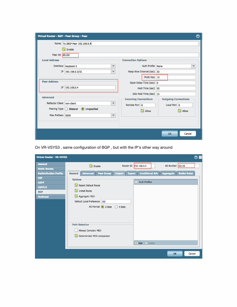
On VR-VSYS3 , same configuration of BGP , but with the IP’s other way around
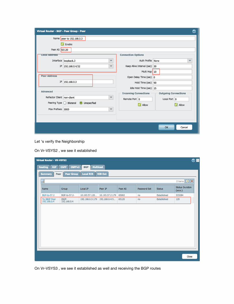
Let ‘s verify the Neighborship On Vr-VSYS2 , we see it established
On Vr-VSYS3 , we see it established as well and receiving the BGP routes

VR-‐VSYS3 is now receiving the BGP routes from VR-‐VSYS2 (VR-‐VSYS2 learned those route from VR-‐VSYS1). Also we notice that VR-‐VSYS2 is preserving the AS-‐PATH prepending done by VR-‐VSYS1 and is advertising the same AS=PATH length to VR-‐VSYS3.
Route Reflector Now that we are adding VSYS and VR to achieve the RR scenario, our logical topology now changed. As a reminder, the current topology now looks like this

The Route Reflector is a BGP routing components that offer an alternative to having all IBGP peer to be in full Mesh (as full mesh doesn’t scale well for large networks ) A fundamental point in Route Reflector (since it is not in full mesh anymore) is the Loop Avoidance and 2 new attributes gets generated. In RR the 2 attributes for this:
• Originator-ID
• Cluster ID The Router ID field is for Originator-ID and Reflector Cluster ID is for the Cluster ID Route Reflector Configurations

Here we use the Next-hop “Use Self” options for the purpose of the lab, but in IBGP you probably want to keep the “ Original “ next-hop.

As you can see, above screenshot show the config of the RR itself (192.168.0.3) and it has the “Reflector Client” option set to “Client”. It does not mean the RR is a client itself, but that the iBGP peering to him (here “192.168.0.5” ) will be his client

The router ID is referring the RR attribute “ Originator ID” The Reflector Cluster ID is referring the RR Attribute “ Cluster ID”
High Availability
Active-Passive When doing Active-Passive, it is important to remember that the passive member is in standby mode, not responding to Arp and does not “own” any IP as the IP address are still owned by the primary . If we take the routing table output of our lab device Active in the HA
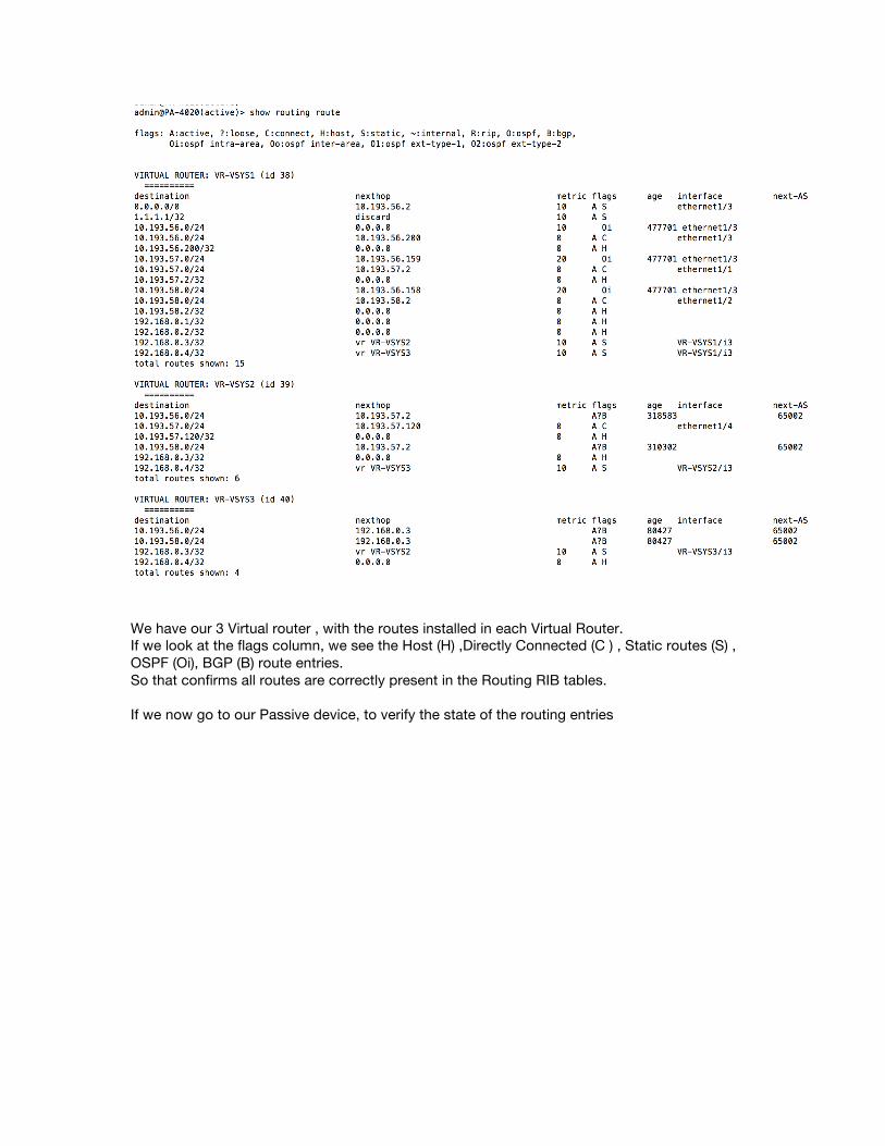
We have our 3 Virtual router , with the routes installed in each Virtual Router. If we look at the flags column, we see the Host (H) ,Directly Connected (C ) , Static routes (S) , OSPF (Oi), BGP (B) route entries. So that confirms all routes are correctly present in the Routing RIB tables. If we now go to our Passive device, to verify the state of the routing entries

If you look on passive, we do not see the same route entries, No OSPF, no BGP, more interestingly not Directly connected, If you look only Host and Static entries, No dynamic routing (as when the failover occurs, the Firewall will re-establish the Neighborship, learn the routes from its neighbor and recalculate the SPT), The directly connected not being present, actually make sense since the Interface and the IP’s are only active on the other Firewall (who is currently the active member and the one who own the IP addresses).
