understanding infrared camera thermal image quality · ploited are low temperature (room...
TRANSCRIPT

Understanding Infrared Camera Thermal Image Quality
www.sofradir-ec.com
Access to the world’s leading infrared imaging technology
Clean Signal
Noise{

Understanding Infared Camera Thermal Image Quality
2 © 2011 Electrophysics Corp.
Infrared Inspection White Paper
You’ve no doubt purchased a digital camera sometime over the past few years to replace your old film camera. It’s likely your purchased was influenced by your belief that the number of pixels was the most important specification when trying to judge image quality between all the camera choices offered.
For anyone that reads Consumers Reports™ and their detailed evalu-ation of digital cameras you’ll appreciate that camera performance includes careful analysis of much more than the pixel count. Because a thermal camera is basically an image converter (radiant thermal energy to visible image) you need to understand only a few attributes that determine thermal image quality; resolution, thermal sensitivity and fixed pattern noise. Often thermal camera brochures offer list specification that you, as a user, may never be able to confirm or even understand. This paper’s objective is to help you simplify your understanding of how image quality is determined.
We will cover three topics that directly influence thermal image qual-ity and discuss a number of related topics as well.
Topics:• Pixel resolution• Thermal sensitivity• Non-uniformity correction
The first consideration is the number of pixels. Today there are three resolution standards (some manufacturers’ cameras deviate slightly):
• Low Resolution – ≤ 160x120 (19,600 pixels) • Medium Resolution – 320x240 (76,800 pixels) • High Resolution – 640x480 (307,200 pixels)
How much resolution you need (verses want) is primarily determined by your application and by the value you give to image quality. When evaluating a digital camera with 5 verses 10 mega pixels most users will never benefit by purchasing a camera with 10 million pixels because they will never print the images on large enough paper where the resolution would provide better print quality. Whereas you will always print and display the full resolution of an infrared camera since the highest resolution available is relatively modest by today’s digital camera standards. Even at 640x480 pixel resolution a high definition thermal image will only take up a fraction of today’s computer displays and the resulting
Understanding Infrared Camera Thermal Image Quality
Pixel Resolution
Abstract

Understanding Infrared Camera Thermal Image Quality
3An ISO 9001 Certified Company.
Infrared Inspection White Paper
thermal image print quality will always be fully realized. Therefore when evaluating a thermal camera the number of pixel is relevant and increased resolution is the most significant consideration in improving image quality.
Another benefit to high resolution is the ability to zoom into a scene and maintain good image quality. The majority of thermal cameras feature a standard optic with a horizontal field of view of approxi-mately 25°. Regardless of pixel resolution the performance of a 640x480 camera set to 2X digital zoom is going to equal the perfor-mance of a 320x240 resolution camera with an optional (and often costly) 12° (2X) lens. If you anticipate the need for imaging objects at distances further than 20 feet you should consider the increased costs of a 2X lens for a 320x240 thermal camera when comparing the total costs between 320x240 and 640x480 systems.
160x120 320x240 640x480
160x120 (4X) 320x240 (4X) 640x480 (4X)

Understanding Infared Camera Thermal Image Quality
4 © 2011 Electrophysics Corp.
Infrared Inspection White Paper
The second major issue that impacts image quality is thermal sensi-tivity. While there are a number of tests used to quantify this specifi-cation, thermal sensitivity basically defines how well the camera will image as you increase image contrast. Thermal sensitivity varies with object temperature, as object temperature increases the slope of the signal output of the detector increases with increased temperature. This means that the signal (increasing) to noise (fixed) ratio improves as you view hotter objects. However this is not usually a benefit because the applications where better thermal sensitivity can be ex-ploited are low temperature (room temperature) applications where the thermal contrast (temperature delta within an image) is very low. Typical low thermal contrast applications include building diagnosis where the camera is imaging interior walls with very little temperature variations or emissivity differences and issues like moisture or insula-tion quality can only be visualized by increasing the contrast to the point where the cameras thermal sensitivity limits the useful tempera-ture span settings.
As you review published camera specifications you will see thermal sensitivity specifications range between 0.25°C (250mK) and 0.05°C (50mK). While you might consider a quarter of degree to be adequate thermal sensitivity as soon as you look at a low contrast scene you’ll discover the image quality adversely effects the image quality as noise begins to dominate the image.
Thermal imagers usually display images in palettes comprised of 256 discreet color or gray levels. Imagine your target has a temperature difference between 0°C and 256°C each gray or color level would represent 1 degree of temperature difference. Now apply this same color mapping into a scene with temperatures between 25°C and 35°C or 10 degrees. Each color now represents 0.03°C (10°C ÷256), a value lower than the most sensitive uncooled cameras. The result is some display of noise. There are many applications in which it is very important to set the span as narrow as possible in order to see the smallest temperature variations possible. If you are using a cam-era with 0.25°C sensitivity and wanted to maintain the same level of noise you would have to set a temperature range of 65°C (150°F) which would likely result in a very low contrast image. You should recognize that the difference between a camera with 50mK sensitiv-ity verses a camera with 100mK sensitivity is 100% better and not as 0.05°C better.
Understanding Infrared Camera Thermal Image Quality
5An ISO 9001 Certified Company.
Infrared Inspection White Paper
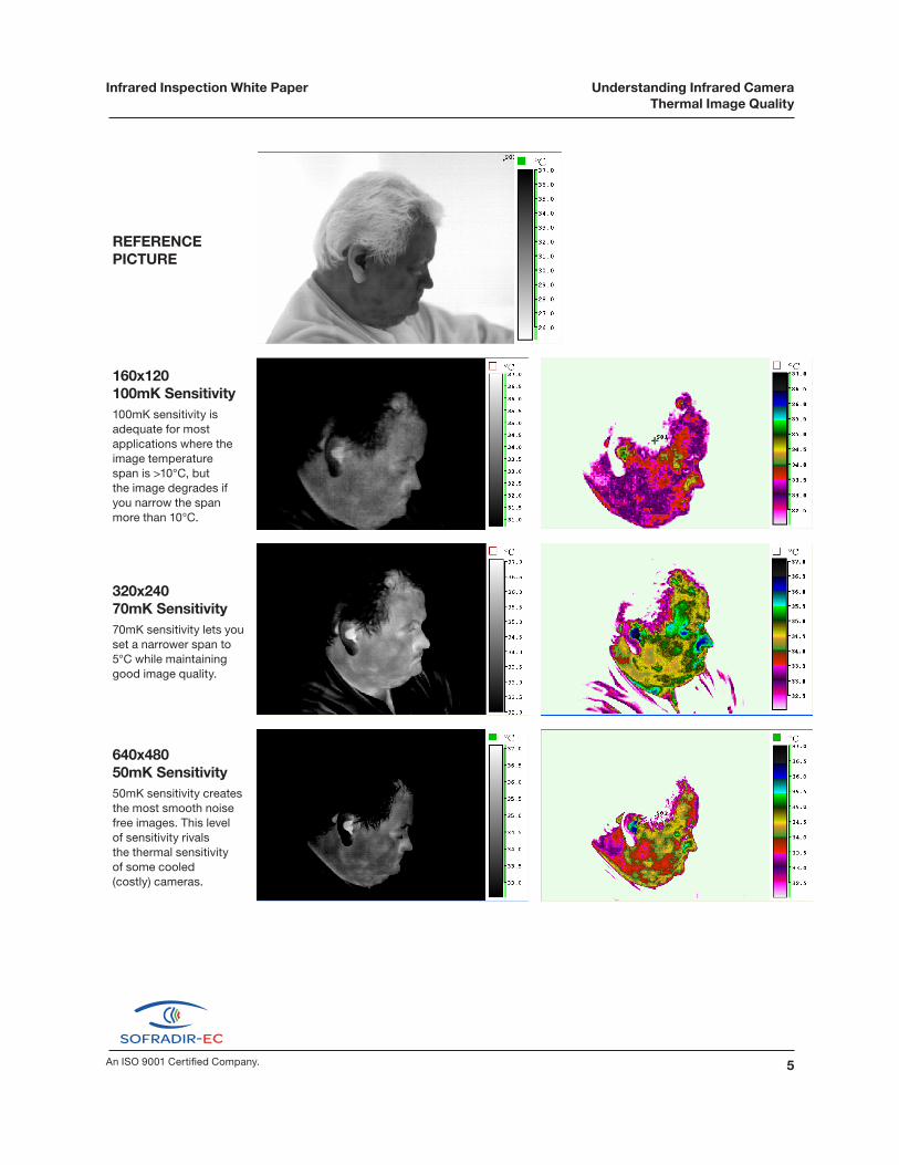
REFERENCE PICTURE
160x120 100mK Sensitivity100mK sensitivity is adequate for most applications where the image temperature span is >10°C, but the image degrades if you narrow the span more than 10°C.
320x240 70mK Sensitivity70mK sensitivity lets you set a narrower span to 5°C while maintaining good image quality.
640x480 50mK Sensitivity50mK sensitivity creates the most smooth noise free images. This level of sensitivity rivals the thermal sensitivity of some cooled (costly) cameras.

Understanding Infared Camera Thermal Image Quality
6 © 2011 Electrophysics Corp.
Infrared Inspection White Paper
NETD – Noise Equivalent Temperature Difference: Quantitative Measurement
NETD is the scene temperature difference equal to either the internal noise of the detector (detector NETD) or the total electronic noise of a measurement system (system NETD). As a camera buyer you need to evaluate system NETD.
The test setup (as shown in Illustration 1) consists of temperature control blackbody reference and some type of ambient (passive) ob-ject that creates a simple slit target for the camera to visualize. The temperature of the black body is adjusted until it nearly equals the ambient target temperature. An oscilloscope measures the analog video output of one horizontal line and at the point where the temper-ature delta between the reference and the ambient targets no longer creates a measureable signal the NETD is determine by the mea-sured temperature difference between the reference and the ambient reference targets. (Illustration 1 – NETD Test Setup)
Thermal Sensitivity Tests
Illustration 1NETD Test Setup
Infrared Camera
Video Output

Understanding Infrared Camera Thermal Image Quality
7An ISO 9001 Certified Company.
Infrared Inspection White Paper
MRTD – Minimum Resolvable Temperature Difference: Qualitative Measurement
This is a system test. An observer is asked to assess the minimum temperature difference at which a 4 bar target (see Illustration 2 – MRTD Test Setup) can be resolved by watching the video output displayed as the temperature set points of the reference and the ambient targets are brought close together. This minimum difference will change with the spatial frequency of the bar target used. A curve of MRTD against spatial frequency is obtained which characterizes the performance of the imaging system. Modern infrared imaging systems can have low spatial frequency MRTDs of tens of milli-kelvins.
The benefits of large format cameras is significant we you combine the need for high sensitivity while viewing high spatial frequencies.
To simplify explaining the fundamentals of thermal sensitivity let’s focus on a single pixel of the infrared sensor in an uncooled infrared camera. Each pixel in an uncooled focal plane array image sensor is essentially a resistor fabricated using MEMS (micro electro mechanical systems).
Illustration 2MRTD Test Setup
Temperature Control As the temperature of the reference is brought closer to the ambient target, a point at which the operator can no longer see, a temperature delta will occur. The temperature difference just before the operator loses the image of the grid is the MRTD.
Understanding Infared Camera Thermal Image Quality
8 © 2011 Electrophysics Corp.
Infrared Inspection White Paper
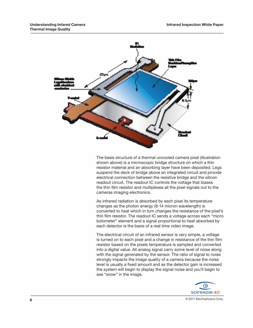
The basis structure of a thermal uncooled camera pixel (illustration shown above) is a microscopic bridge structure on which a thin resistor material and an absorbing layer have been deposited. Legs suspend the deck of bridge above an integrated circuit and provide electrical connection between the resistive bridge and the silicon readout circuit. The readout IC controls the voltage that biases the thin film resistor and multiplexes all the pixel signals out to the cameras imaging electronics.
As infrared radiation is absorbed by each pixel its temperature changes as the photon energy (8-14 micron wavelength) is converted to heat which in turn changes the resistance of the pixel’s thin film resistor. The readout IC sends a voltage across each “micro bolometer” element and a signal proportional to heat absorbed by each detector is the basis of a real time video image.
The electrical circuit of an infrared sensor is very simple, a voltage is turned on to each pixel and a change in resistance of the thin film resistor based on the pixels temperature is sampled and converted into a digital value. All analog signal carry some level of noise along with the signal generated by the sensor. The ratio of signal to noise strongly impacts the image quality of a camera because the noise level is usually a fixed amount and as the detector gain is increased the system will begin to display the signal noise and you’ll begin to see “snow” in the image.

Understanding Infrared Camera Thermal Image Quality
9An ISO 9001 Certified Company.
Infrared Inspection White Paper
The signal level of this noise is commonly specified as Noise Equivalent Temperature Difference.
Like any electrical circuit there are a lots of opportunities for electri-cal noise to get into systems, but the quality (signal to noise) of the signal coming directly off the infrared pixel has the most impact on thermal sensitivity, since nearly all camera developers have access to the same electronic components with which to create a camera. Therefore the thermal sensitivity in large part is based on the quality of the infrared imager array.
Clean Signal
Noise{

Understanding Infared Camera Thermal Image Quality
10 © 2011 Electrophysics Corp.
Infrared Inspection White Paper
Other issues like the f number of the lens also impact thermal sensitivity. Your camera’s lens is likely ƒ1.0 (the focal length is equal to the lens diameter) which is considered a “fast” lens. By comparison the f number in your digital camera is likely between ƒ3 and ƒ5 while the cameras used in cell phones and other low cost systems can be as high as ƒ20! As application demands lead to longer focal length lenses it is practical to go to “slower” optics in order to reduce the size, weight and cost of telephoto lenses and trade off some thermal sensitivity. For example, an F1.4 optic will result in 2X reduction in thermal sensitivity and an F2.0 optic a 4X reduction in thermal sensitivity. Therefore a system with 50mK sensitivity using a standard lens will still maintain good sensitivity (100mK) when a ƒ1.4 telephoto lens is attached to the camera verses another camera whose thermal sensitivity started at 100mK and becomes 200mK when viewing through a “slower” (ƒ number higher than 1).
As you can see from the various issues raised within this paper the nature of thermal sensitivity is very complex but in the real world the human eye is extremely good at differentiating small differences in image quality that you’ll know it (good sensitivity) when you see it.
As the number of pixels increases and their sensitivity improves the quality of image is increasingly dependent on a process called Non Uniformity Calibration or NUC. As we described earlier a microbolometer imaging array is essentially an array of tiny resistors and because of the micro scale of these devices there are variations in how each pixel responds to the infrared energy from an object.
During manufacturing the infrared camera’s sensor must be normalized, meaning that the differences in response and DC output for each detector must be zeroed out. Here are two images from a camera. The first is what a typical image looks like without any corrections and the other the result of the calibration correction. Thermal cameras typically feature an internal flag or iris that periodically is positioned in front of the detector as a constant temperature reference to zero out differences amongst the pixels. This is a fine tuning of the factory NUC process and is sometimes referred to as a “touch up”.
Non-Uniformity Correction

Understanding Infrared Camera Thermal Image Quality
11An ISO 9001 Certified Company.
Infrared Inspection White Paper
Because the touch up source is inside the lens, additional image quality improvements are possible when performing a touch up calibration through the lens either using a lens cap or exposing the camera to a large uniform surface. As camera performance improves the non uniformities created by the lens will begin to be seen and for the ultimate image quality a simple through the lens calibration step will ensure the highest image quality the camera is capable of generating.
Benefits of high increased image quality:• Much greater flexibility to inspect targets are varying distances• Ability to visualize low thermal contrast targets• More intuitive diagnosis of heat related problems• Improved infrared visible fused image quality due to better
matching of infrared and visible camera resolution..• Flexibility to incorporate lower cost and lighter weight optional
lenses• More intuitive diagnosis of temperature anomalies
Image 1: Uncorrected Image Image 2: Corrected Image

For more information on our Products visit:
www.sofradir-ec.com
373 US Hwy 46W Fairfield, NJ 07004 973-882-0211 Fax: 973-882-0997 [email protected] www.sofradir-ec.com
Ed
ition
: 07
-11
rev0
8