uml 2.0 with vizzanalyzer - visualization of class diagrams205420/fulltext01.pdf · uml 2.0 with...
TRANSCRIPT

School of Mathematics and Systems Engineering Reports from MSI - Rapporter från MSI
UML 2.0 with VizzAnalyzer
- Visualization of class diagrams
Yun Liu
Sep 2007
MSI Report 07113 Växjö University ISSN 1650-2647 SE-351 95 VÄXJÖ ISRN VXU/MSI/DA/E/--07113/--SE

Abstract
The program analysis tool, VizzAnalyzer, works good for visualizing the program structure as graphs, but currently it does not allow for a UML conform visualization, which allows a effective communication among software engineers. In this thesis we describe the extension of the VizzAnalyzer to allow the visualization of software systems as UML class diagrams.
The Eclipse platform provides an open source platform for creating an extensible integrated development environment. We create a plug-in that can be seamlessly integrated in the Eclipse platform through the third party tools in Eclipse to visualize the graph in VizzAnalyzer as UML class diagrams. The third party tools that are used in this thesis are the Graphical Editing Framework (GEF) and Draw2D. They are mainly used to create the UML class diagram view.
In order to get a clear view on the diagram in the limited screen size, it is necessary to provide an appropriate layout for the diagram and drag and zoom actions on its figures. We provide the necessary means and document altogether in this thesis. We implement our solution as Eclipse plug-in and demonstrate feasibility. Key words: Plug-in, GEF, Draw2d, UML, graph, class diagram, extensible, analysis
i
Table of Contents
Abstract..............................................................................................................................................i Table of Contents ..............................................................................................................................ii List of Figures..................................................................................................................................iv List of Tables ....................................................................................................................................v Glossary ...........................................................................................................................................vi 1 Introduction....................................................................................................................................1
1.1 Context of the thesis............................................................................................................1 1.2 Problem Description ...........................................................................................................1 1.3 Goals and Criteria ...............................................................................................................1 1.4 Motivation...........................................................................................................................2 1.5 Outline ................................................................................................................................3
2 Technology Background ................................................................................................................4 2.1 Java .....................................................................................................................................4 2.2 UML2.0...............................................................................................................................4
2.2.1 Things ......................................................................................................................5 2.2.2 Relationships............................................................................................................7 2.2.3 Diagram....................................................................................................................9
2.3 Eclipse Plug-in ..................................................................................................................10 2.4 Draw2d and GEF framework............................................................................................10
3 Requirements ............................................................................................................................... 11 3.1 Users ................................................................................................................................. 11 3.2 Features............................................................................................................................. 11 3.3 Use cases...........................................................................................................................12
3.3.1 Use Case Model .....................................................................................................12 3.3.2 Use Cases ...............................................................................................................13
3.4 Functional requirements....................................................................................................16 4 Architecture..................................................................................................................................20
4.1 The Eclipse architecture....................................................................................................20 4.1.1 The Eclipse Plug-in Model.....................................................................................21 4.1.2 Plug-in Deployment and Activation.......................................................................22 4.1.3 Dependency............................................................................................................22 4.1.4 Extension................................................................................................................23
4.2 Draw2d and GEF framework............................................................................................23 4.2.1 Draw2d...................................................................................................................23 4.2.2 GEF........................................................................................................................26
4.3 Architecture of our product ...............................................................................................30 5 Design and implementation .........................................................................................................31
5.1 Prerequisites......................................................................................................................31 5.2 Plug-in...............................................................................................................................31 5.3 GEF...................................................................................................................................33
5.3.1 Model .....................................................................................................................34 5.3.2 Figure .....................................................................................................................36 5.3.3 EditParts.................................................................................................................39
ii

5.3.4 PartFactory.............................................................................................................41 5.3.5 Create GraphicalView............................................................................................41
5.4 Drag and Zoom actions.....................................................................................................43 5.5 Analysis of the gml file .....................................................................................................44
6 Conclusion and Future work........................................................................................................47 6.1 Conclusions.......................................................................................................................47 6.2 Future work.......................................................................................................................48
Reference ........................................................................................................................................49 Appendix A.....................................................................................................................................50
A.1 Installation........................................................................................................................50 A.2 Loading GML file ............................................................................................................52
iii

List of Figures
Figure 2.1: Hierarchy chart .....................................................................................................10 Figure 3.1: Use Case Model....................................................................................................12 Figure 4.1: Eclipse architecture ..............................................................................................20 Figure 4.2: Plugin.xml ............................................................................................................22 Figure 4.3: Draw2d architecture .............................................................................................24 Figure 4.4: Draw2d border types ............................................................................................25 Figure 4.5: Three connection patterns with different router ...................................................26 Figure 4.6: A ChopboxAnchor calculates the connection endpoint ........................................26 Figure 4.7: GEF architecture...................................................................................................27 Figure 4.8: A high-level view of GEF.....................................................................................27 Figure 4.9: EditPart object ......................................................................................................28 Figure 4.10: Communication chain Request – EditPart - Command......................................30 Figure 5.1: Configuration of Load file action .........................................................................32 Figure 5.2: UMLClassDiagram plugin.xml ............................................................................33 Figure 5.3: Model class diagram.............................................................................................35 Figure 5.4: An example for creating an image........................................................................36 Figure 5.5: Figure Class Diagram...........................................................................................37 Figure 5.6: Some of the visibility icons ..................................................................................37 Figure 5.7: An example of result of methodList figure...........................................................38 Figure 5.8: An example of result of the SubjectFigure ...........................................................39 Figure 5.9: EditPart class diagram ..........................................................................................39 Figure 5.10: Code of the PartFactory......................................................................................42 Figure 5.11: Three methods in DiagramEditor .......................................................................43 Figure 5.12: Process of the drag and zoom actions.................................................................43 Figure 5.13: An example of the class diagram of a gml file ...................................................46 Figure A.1.1: Exporting plug-in menu ....................................................................................50 Figure A.1.2: Selecting JAR file as exporting way.................................................................51 Figure A.1.3: Browsing the directory......................................................................................51 Figure A.2.1: The UMLClassDiagram plug-in running in the run-time workbench...............52 Figure A.2.2: Loading GML file menu ...................................................................................52 Figure A.2.3: Loading GML file dialog ..................................................................................53 Figure A.2.4: GML file loaded................................................................................................53 Figure A.2.5: Good layout with drag and zoom actions..........................................................54
iv

List of Tables
Table 2.1: UML things ..............................................................................................................7 Table 2.2: UML relations ..........................................................................................................8 Table 2.3: UML diagram classification.....................................................................................9 Table 3.1: Features ..................................................................................................................12 Table 3.2: Use Cases ...............................................................................................................16 Table 3.3: Requirements .........................................................................................................19 Table 5.1: Node properties in gml file ....................................................................................45 Table 5.2: Edge properties of the gml file...............................................................................45
v
Glossary
API Application Programming Interface AWT Abstract Window Toolkit EMF Eclipse Model Framework GEF Graphical Editing Framework GUI Graphic User Interface IDE Integrated Development Environment JDK Java Development Kit JDT Java Development Tools LWS LightweightSystem MVC Model-View-Controller OMT Object Modeling Technique OOSE Object-Oriented Software Engineering PDE Plug-in Development Environment (PDE) SDK Software Development Kit SWT Standard Widgets Toolkit UML Unified Modeling Language VM Virtual Machine
vi

1 Introduction
This chapter gives a description of problem solved by this thesis and the goals and criteria need to meet by designing and implementing of our program. Furthermore it describes the motivation to do this thesis and how its architecture is organized.
1.1 Context of the thesis
The VizzAnalyzer Framework is a program analysis tool that can be used for analysing software programs and for visualizing their internal structure as graphs. Currently the connected visualization plug-ins allow not for a UML conform visualization, this situation need to be changed. To solve this problem, the authors of the VizzAnalyzer plan to develop a visualization plug-in for Eclipse using its UML2.0 features to visualize programs analysed by the VizzAnalyzer as UML2.0 class diagram. By taking advantage of the existing frameworks of this platform, it will allow exporting the graph information stored in the VizzAnalyzer to Eclipse UML2.0 for viewing them as UML diagrams. In addition, appropriate layout algorithms need to be implemented to present the elements and relations in the diagrams in a clear way.
1.2 Problem Description
The VizzAnalyzer is a program analysis tool that can be used for analysing software programs and for visualizing their internal structure as graphs. The currently connected visualization plug-ins allow not for a UML conform visualization. The problem addressed by this thesis is an extending task, which is to use the existing framework to write a visualization plug-in connecting Eclipse UML2 to the VizzAnalyzer. This will allow exporting the graph information stored in the VizzAnalyzer to Eclipse UML2 for viewing them as UML diagrams.
This task is difficult to solve, since GEF, EMF and UML2.0 are complex frameworks. It is necessary to understand the framework well and use them correctly. Furthermore, UML2.0 should be understood well, that means it is necessary to know all the diagrams and when and how to use them. Additionally, a plug-in extending the Eclipse GUI during program start with menu entries should be well designed. Finally, it is necessary to layout the UML diagrams using appropriate layout algorithms for UML 2.0 diagrams.
1.3 Goals and Criteria
This section describes the goals pursued by this thesis in order to solve the problem and the criteria used for validating the goals:
The first goal is to get a good understanding the UML 2.0 class diagrams including the classes and its relationships, in order to show the graph stored in VizzAnalyzer in UML class diagrams. The relevant parts of UML shall be documented. This goal is met by learning UML 2.0 and documenting the elements and relations used in class diagrams. Additionally a mapping from
1

the elements and relations contained in the VizzAnalyzer graphs to the elements and relations of UML class diagrams shall be defined. The important part of this goal is to analyse the relationships among all the graph structure fields. That means to define which class or interface contains what kinds of attributes and methods. Furthermore, the return type and parameters of method, type of attribute and if there are invokes among the method can help to get the relationship between classes. Also the assesses,extends and implements information can be got from the edges from the VizzAnalyzer graph will provide the relationships between two classes or interfaces.
The second goal is to get access to the result graph of the VizzAnalyzer, in order to analyse its structure to allow getting the elements defined in the mapping. These are in particular: class, interface, attributes, methods and the relationships among these elements. This goal is fulfilled when the Grail (the graph data structure used by VizzAnalyzer) and GEF API and related information from the authors of VizzAnalyzer has been studied, and architecture has been defined to pass the information to the UML model which will be build in the GEF framework. Together with the results from our first goal the proper elements and relations can be drawn and shown in the GUI.
The third goal is the design and implementation of the mapping as a plug-in for Eclipse. It will allow user interaction by extending the menu to load the graph from the VizzAnalyzer. This goal is fulfilled if a Eclipse plug-in has been developed which can load a graph generated and stored by the VizzAnalyzer. Basic functionalities as load graph, save graph and open graph are essential. Furthermore, the editor for displaying the UML diagrams from GEF framework must be loaded on the plug-in startup.
The last goal is to offer functions which allow to show the UML class diagram, for the VizzAnalyzer using GEF framework from Eclipse platform. This means to provide drag, and zoom actions for the classes or interfaces in the diagram should be implemented since the space for display diagrams is limited, so the size the class and interface figures would not be so big to show all the information in it. To avoid overlaps among the figures or connections an appropriate layout algorithm should be designed and implemented to avoid the overlaps as few as possible.
1.4 Motivation
Eclipse is supported by more and more software providers including IBM, RedHat, Borland, Rational, and others. It becomes one of the most famous development platforms now. Furthermore, the Eclipse platform provides the two general areas of functionality, Java Development Environment and Tools Integration Platform. As a Java development environment, Eclipse can be used to write and debug Java programs very effectively. Additionally, Eclipse delivers a good general-purpose IDE and tool integration platform. [1] Everything in Eclipse is implemented as a plug-in or a set of related plug-ins. So it is very convenient for us to develop our own plug-in and integrate
2

it into Eclipse. Furthermore, Eclipse is a free, open source platform. It reduces the development costs. Since the provided framework provides much functionality. Thus we can reduce the development and maintenance effort and to focus on the functions we really want, thereby increasing the acceptance by the users.
1.5 Outline
The structure of this paper thesis is as follows, Chapter 2 describes technical background about Java language, UML 2.0 diagrams, Eclipse plug-in development, and GEF framework. This information is needed to understand the rest of the thesis. Chapter 3 presents an overview about features, use cases and functional requirements for the extended function of the VizzAnalyzer. Chapter 4 describes the architecture for Eclipse Platform and its plug-in model and the two used plug-ins: draw2d and GEF framework. Chapter 5 describes the design and implementation of the Eclipse plug-in, which shows the UML class diagrams. Finally, Chapter 6 concludes the thesis and describes future work.
3

2 Technology Background
This section describes the technologies which are that are referenced throughout this thesis. It gives a brief description of the Java programming language, UML 2.0 class diagrams, the Eclipse plug-in architecture, and the Draw2d and GEF frameworks.
2.1 Java
Java is an object-oriented applications programming language developed by Sun Microsystems. Object-oriented is one of the main features of Java language. It allows using user-defined types and related operations when designing software. The object-oriented design makes it much easier to manage, plan and design large software projects, increasing the health of projects and decreasing the amount of failed projects. Another advantage is that it can generate many classes which have some kind of relationships among others so that it will be easy for the software redevelopment. When the second time software developers want to make some new plug-ins to enhance the functionality of their software, they definitely would not want to see the jumbled program codes. And the goal of object-oriented is to write code which is easy to understand and reuse.
The second feature of Java is that it is platform independent, which means that programs written in Java can run on any hardware platform without any changes after compiling. This is usually called “compile once, running anywhere.” This is performed by generating bytecode (simplified machine instructions, specifically called Java bytecode) when compiling the java language by most java compilers. The code is then running on a java virtual machine (VM) which is a program written in native code on the host hardware. The VM will then interpret and execute the java bytecode by converting it to the native code. Then the standardized libraries will be opened by the java VM to load and save data.
Another important feature of java language is its automatic garbage collection. Programmers don’t need to care much about the memory allocation and de-allocation, and resulting problems, such as memory leaks. It saves the programmer a lot of effort on the management of object and memory allocation and release, so that they can mainly focus on the functional programming. [2]
“Java derives much of its syntax from C and C++ but has a simpler object model and fewer low-level facilities.”[2]. With the above described features, Java is very functional but much easy program language than other programming languages.
2.2 UML2.0
UML, the Unified Modeling Language, is a standardized specification language for object modeling, developed by Rational Software Company by unifying some of the leading object-oriented modeling methods. [3]
Booch by Grady Booch OMT (Object Modeling Technique) by Jim Raumbaugh OOSE (Object-Oriented Software Engineering) by Ivar Jacobson
4

Many companies are looking for techniques to automate the software production, improve the quality and reduce the cost since the great increasing of the strategic value of software. And businesses also need to manage the complexity of systems as they increase in scope and scale. “In particular, they need to solve the recurring architectural problems, such as physical distribution, concurrency, replication, security, and load balancing and fault tolerance.”[4] The Unified Modeling Language (UML) was to satisfy those requires.
UML is an exoteric method for visualizing, specifying, constructing, and documenting the artifacts of developing object-oriented software-intensive systems. UML is used for software system modeling which includes analysis and design. In the field of analysis, first it is described by a set of requirements, and then the system parts are identified on a high level. It is followed by the design phase which is to specify these identified system parts and their interactions in detail. During the early phases of software projects, UML identifies and specifies the requirements as use cases. Then it uses class diagrams or component diagrams for the identification of system parts on a high level. In the design phase, UML uses class diagrams, interaction diagrams, component diagrams and state chart diagrams to describe the different parts in the system.
The definition of UML is comprised of diagrams and core models. The diagram is syntax and core model is semantic. UML contains three basic building blocks: things, relationships and diagrams. The following sections will introduce these three basic building blocks of UML.
2.2.1 Things
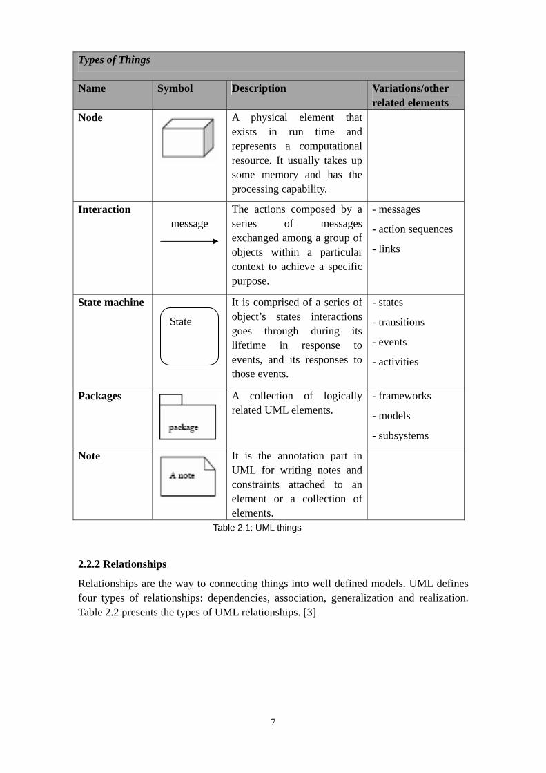
Things are the final result of the abstraction of entities. They are the basic members in models. UML contains structural things, behavioral things, grouping things and annotational things. Table 2.1 present the details of the types of things in UML [3].
5

Types of Things
Name Symbol Description Variations/other related elements
Class A set of objects which have the same attribute, operations, relationships and semantics.
- actors
- signals
- utilities
Interface A collection of operations which describe the service of a class or component.
Collaboration Describe a group of classes which implement some kind of task cooperatively and the relevant set with these classes. It is used to modeling the use cases implementation.
Actor
A person or an external device who communicates with the system.
Use Case Define an observable result of value which is performed by the interaction between a particular actor and the system. Used to structure behavioral things in the model.
Active class
A class whose objects own one or multiple processes or execution thread, therefore it can initiate a control activity on their own. It is similar to the class except that the behavior of the element represented by its object exists with other elements simultaneously.
- processes
- threads
6
Types of Things
Name Symbol Description Variations/other related elements
Node
A physical element that exists in run time and represents a computational resource. It usually takes up some memory and has the processing capability.
Interaction message
The actions composed by a series of messages exchanged among a group of objects within a particular context to achieve a specific purpose.
- messages
- action sequences
- links
State machine It is comprised of a series of object’s states interactions goes through during its lifetime in response to events, and its responses to those events.
- states
- transitions
- events
- activities
Packages
A collection of logically related UML elements.
- frameworks
- models
- subsystems
Note
It is the annotation part in UML for writing notes and constraints attached to an element or a collection of elements.
State
Table 2.1: UML things
2.2.2 Relationships
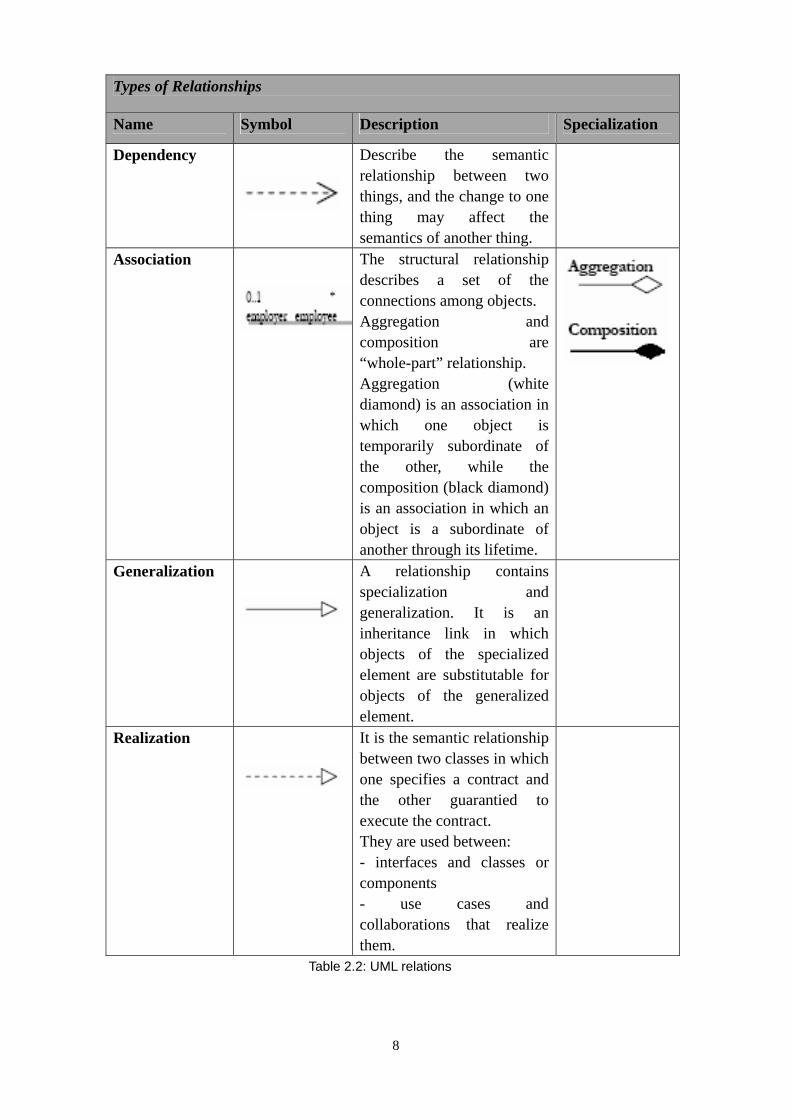
Relationships are the way to connecting things into well defined models. UML defines four types of relationships: dependencies, association, generalization and realization. Table 2.2 presents the types of UML relationships. [3]
7
Types of Relationships
Name Symbol Description Specialization
Dependency Describe the semantic relationship between two things, and the change to one thing may affect the semantics of another thing.
Association The structural relationship describes a set of the connections among objects. Aggregation and composition are “whole-part” relationship. Aggregation (white diamond) is an association in which one object is temporarily subordinate of the other, while the composition (black diamond) is an association in which an object is a subordinate of another through its lifetime.
Generalization A relationship contains specialization and generalization. It is an inheritance link in which objects of the specialized element are substitutable for objects of the generalized element.
Realization It is the semantic relationship between two classes in which one specifies a contract and the other guarantied to execute the contract. They are used between: - interfaces and classes or components - use cases and collaborations that realize them.
Table 2.2: UML relations
8

2.2.3 Diagram
Diagram is a sort of the set of things. UML contains ten types of diagrams, below is a list and brief description of them.
Class diagram; it describes the classes contained in the system, the structure of the system and the relationships among the classes.
Object Diagram; it is a specific instance of the class diagram. Package Diagram; it represents packages and the dependent class diagram in
them. Component Diagram; it describes the physical structure of code parts and the
organization and dependencies among a set of components. Deployment Diagram; it defines the physical system structure of the software
and hardware in the system. Use Case Diagram; it describes the system function and requirement from the
user’s point of view and shows a set of actors outside the system and how they interact with a set of use cases inside the system.
Sequence Diagram; it shows the interaction between a set of objects Collaboration Diagram; it shows the collaboration between a set of objects. It
focuses on the structural ordering of objects that send and receive messages. State Chart Diagram; it describes all the possible states of a set of objects and
the state transition conditions when these events and activities occurs. Activity Diagram; it describes the execute order of all the activities in the
system.
All these ten diagrams can be reduced to five classifications. Table 2.3 shows the UML diagram classifications.
Types Descriptions Contains
Static diagram Describe the static structure of system
Class diagram, Object diagram, Package diagram
Behavior diagram Describe the dynamic model of the system and interactions among its comprised objects
State Chart diagram, Activity diagram
Use Case diagram Describe the system function from the user’s point of view and indicate their actors.
Use Case diagram
Interaction diagram Describe the interactions among a set of objects
Sequence diagram, Collaboration diagram
Implementation diagram
Show the physical structure and dependencies among its parts
Component diagram, Deployment diagram
Table 2.3: UML diagram classification
9

Figure 2.1 is a hierarchy chart to categorize them hierarchically. [5]
Figure 2.1: Hierarchy chart
2.3 Eclipse Plug-in
Eclipse plug-in is the smallest function unit of the Eclipse Platform. The Eclipse Platform is comprised of a set of plug-ins. Each plug-in contains one or more .jar file and a description file, the XML manifest file. Eclipse Platform defines a group of program plug-in and provides a runtime environment to the program in this pattern. It manages the deployment and activation of the plug-ins depend on the manifest file to provide interfaces for every plug-in. This pattern implements the split of mechanism and policy. The Eclipse Platform implements the mechanism while the plug-in wrote by the developer implements the policies. We can imagine that the Eclipse Platform is something like the Windows operating system, and the plug-in can be seen as the window applications for the operation system. More details about the Eclipse Plug-in will be described in the plug-in model part in the Architecture section.
2.4 Draw2d and GEF framework
The Graphical Editing Framework (GEF) provides support for building rich, interactive user interfaces which are not easily built by native widgets in the base Eclipse Platform. The GEF component is comprised of two plug-ins: Draw2d and GEF. Draw2d, the plug-in org.eclipse.draw2d, is a lightweight toolkit for painting and layout on an SWT Canvas. GEF, the plug-in org.eclipse.gef, is an interactive MVC framework built on top of Draw2d. All graphical visualization is done via the Draw2d framework. More details about these two plug-ins (Draw2d and GEF) including their architecture will be described in the Architecture section.
10

3 Requirements
This section provides an overview about the requirements specification for the UML class diagram visualization. The product is supposed to provide a plug-in for Eclipse using its UML 2.0 features to visualize programs analysed by the VizzAnalyzer as UML 2.0 class diagrams. In order to take good advantage of the GEF framework, the product is using the model-view-controller (MVC) model. It is integrated with the plug-in structure and consists of different components. This will lead to an easy reuse and maintenance. Since all the components will be run on one computer, so the communication between different components will use messages and method calls. It consists out of two mainly functions. One is to display the generated class diagram in suitable position. The other is to load and analysis the original graph stored in VizzAnalyzer to generate the class diagram. The following sections describe the users involved in the system and the main features of the system.
3.1 Users
The users are developers and consultants. They use the VizzAnalyzer to analyse the program to get the original graph information, and then interact with the visualization plug-in, such as loading file. As a result, they get the UML class diagram visualization with which they can interact by dragging and zooming in or out the displayed diagrams to get more details.
3.2 Features
Feature 01 A Eclipse plug-in with a menu entry and a view Description: The product should be a plug-in for Eclipse platform. It has a
menu entry allowing a user to load a “original” file containing the analysis result of the VizzAnalyzer. The plug-in also needs to have an editor to display the converted UML class diagram.
Feature 02 Use GEF Framework
Description: The product uses the GEF framework to display class diagrams. It constructs the models and figures for different parts of the class diagrams, for example, class, method, attribute and connections. Then associate with the analysed information from the “original” file.
Feature 03 Capability to analysis the original graph
Description: The product needs to analyse the original graph (.gml file) to get information for displaying the class diagram. It uses the Grail API to get the node and edge from the gml file, and then decides the type of elements it contains and the relationship among those elements.
11

Feature 04 Layout algorithm for diagram displaying
Description: The perspective should have a suitable layout algorithm to avoid the overlap among all the elements in the class diagram, such as, class overlap, connection overlap.
Feature 05 Drag and zoom action to get more detail of the diagram
Description: In the display view, the layout can not eliminate all the overlaps, and the size of class diagram can not be too large to show all the information in it when there are too much attributes or methods belong to it. In order to let the user get all the details of the class, drag and zoom actions are added to solve these problems.
Table 3.1: Features
3.3 Use cases
This section provides an overview for the Use Case Model and Use Cases from the features described above.
3.3.1 Use Case Model
Figure 3.1 presents the diagram of the use case model. It describes all the actors and the way they are interacting with the system in each use cases.
Figure 3.1: Use Case Model
This figure shows the Use Case Model for the product, Eclipse plug-in, which is extending the VizzAnalyzer’s function to show its analysed program in UML class diagram.
12

3.3.2 Use Cases
In the following, we show the details of the Use Cases. Each use case gives one or more scenarios to indicate how the user should interact with the system to achieve the specific goal. Each use case has a name, goal, pre-condition, post-condition, trigger events, description, extensions and alternatives.
Use Case UC1 Load file Feature: F01, F02, F03, F04, F05
Goal Allow a user to load the graph stored in VizzAnalyzer to display as UML class diagram.
Pre-condition The input file must be of the right format. It should be the graph resulted by VizzAnalyzer analysing the selected program.
Post-condition The load action from the menu from the Eclipse plug-in will be executed.
Actors User
Triggering event User presses the menu, choose load file option. The user can get the class diagram from the original graph information.
Description 1. The user selects the load file option from the menu. 2. The system shows a load dialog. 3. The user chooses the path of the original graph (.gml file)
and selects the file. 4. User presses the “OK” button. 5. The system loads the gml file and analyses the file
information through the Grail API. By the support of the GEF framework, the class diagram’s models, figures, and the related edit parts are provided to the system.
6. According to the analysing information, the system creates the related models, for example, classes, attributes, methods and connections.
7. The system uses the edit parts to draw the figures of the class diagram.
8. The system displays the diagram in the editor perspective with the right layout.
9. The drag and zoom actions were added to the editor so that the user can get the diagram information in more details.
Extensions None
Alternatives The user didn’t choose the right file format, so the system can not open the file and displays an error message. Additionally, the user can press “Cancel” button when choosing the gml file, then the file will not be loaded.
13

Use Case UC2 Save diagram Feature: F01, F05
Goal Allow a user to store the current displaying class diagram into a persistent file.
Pre-condition None.
Post-condition The save action from the menu from the Eclipse plug-in will be executed.
Actors User
Triggering event User presses the menu, choose save diagram option. The user can save the displaying class diagram to a persistent file so that he can get the information much more conveniently since he doesn’t need to reload the original gml file again.
Description 1. The user needs to choose the save diagram option from the menu.
2. A save dialog will be showed. 3. The user chooses the path and input the name of the saved
diagram. 4. User presses the “Save” button. 5. Then the system stores all information of the diagram in the
current working environment in the file.
Extensions None
Alternatives The system can not save the file and displays an error message. Additionally, the user can press “Cancel” button when saving the diagram file, then the file will not be saved.
Use Case UC3 Open diagram Feature: F01, F04, F05 Goal Allow a user to open an existing class diagram in the plug-in
perspective.
Pre-condition The input file must be of the right format.
Post-condition The open action from the menu from the Eclipse plug-in will be executed.
Actors User
Triggering event User presses the menu, choose open diagram option. The user can get the existing class diagram displayed when he want to get the diagram information. This allows him not to reload and analysis the original gml file again.
Description 1. The user needs to choose the open diagram option from the menu.
2. Then an open dialog will be showed.
14

3. The user chooses the path and selects a class diagram file. 4. User presses the “Open” button. 5. Then the system loads the class diagram and displays it in
the plug-in perspective.
Extensions None
Alternatives Since the user didn’t choose the right file format, the system can not open the class diagram file and displays an error message.
Additionally, the user can press “Cancel” button when opening the diagram file, then the file will not be loaded and opened.
Use Case UC4 Analysis file Feature: F03
Goal Allow the system to analyse the received gml file from UC1 to prepare for the diagram displaying.
Pre-condition The file must be received first and has the right format.
Post-condition The gml file will be analysed to get different information to create the related models for GEF.
Actors None
Triggering event The system receives the gml file, here it means getting the path of the file in the computer. Then the system can analyse the file with Grail API to have the class diagram information. With this information, the GEF can create the models, figures and related EditParts. Then it can display the right class diagram based on the gml file.
Description 1. The system needs to get the path of the gml file in the computer.
2. Then the Grail API will be used to analyse the file from the nodes and edges in it to pick up the information.
3. According to the analysed information, the system then creates models for them.
Extensions None
Alternatives Since the user didn’t choose the right file format, the system can not analysis the file and displays an error message.
Use Case UC5 Display class diagram Feature: F02, F04
Goal Allow the system to display the right class diagram based on the gml file with GEF framework.
Pre-condition The models of the class diagram should be created according to the information of the analysis file.
15

Post-condition The right class diagram based on the gml file will be displayed in the Editor view.
Actors None
Triggering event The system get the analysed information from the gml file, then the system will create the models in GEF, and then based on these models, creates the figures and related EditParts. Then with the PartFactory in GEF connecting these three components. At last, in the GraphicalViewer, set this PartFactory and the right layout for the class diagram, it will have the class diagram displayed in the GraphicalViewer.
Description 1. The system needs to get the analysed information from the gml file.
2. Then the system creates the related models in GEF. 3. Then the system generates the figures and EditParts
corresponding to the models and the PartFactory. 4. The GraphicalViewer have the models as its content and the
PartFactory in its configuration. Then it will have the class diagram displayed.
Extensions None
Alternatives Since the system may not get the analysed information, it will not display the class diagram.
Table 3.2: Use Cases
3.4 Functional requirements
This section describes the important functional requirements for the VizzAnalyzer extension. It contains the functions and tasks that the system is required to provide and perform as well as the corresponding Use Cases.
Requirement R01 Eclipse plug-in Event / Use Case: UC1, UC2, UC3
Description: The product shall be a plug-in for Eclipse. It is an extension for Eclipse which shall integrate seamlessly with the workbench and with other plug-ins. The plug-in extends the Eclipse GUI during program should start with menu entries.
Rationale: Eclipse is an extensible platform for tool integration through using plug-ins. Thus, it allows for additional development and integration with the workbench or other plug-ins. The functionality is available over the menu structure.
Fit Criterion: The user should be able to access the different functions over a menu.
16

Requirement R02 Load gml file Event / Use Case: UC1
Description: The product shall implement the function that allows loading the original graph file, then the file can be analysed and converted to UML class diagram.
Rationale: The system needs to export the graph information stored in the VizzAnalyzer to Eclipse UML 2.0 for viewing them as UML class diagrams.
Fit Criterion: The user can execute the load file action to input the original file.
Requirement R03 Analysis the gml file Event / Use Case: UC4
Description: The product shall have the function to analysis the original file to get the detailed diagram information, for example, classes and its relationships.
Rationale: The system needs to analyse the gml file so that the result can be used to have the UML class diagram displayed. Since the original graph is the analysed result from VizzAnalyzer, so we need to use its supported API to get all necessary information, and then assign the models defined in our GEF models to the result information. This allows creating the view of the UML class diagram.
Fit Criterion: The plug-in perspective displays the right class diagram.
Requirement R04 Use Draw2d and GEF framework Event / Use Case: UC5
Description: The product shall have the finally UML class diagram displayed by using the GEF framework in Eclipse.
Rationale: The system needs to view the analysed information as UML class diagram. We use the GEF framework to create class diagram. GEF viewers are based on Model-View-Controller (MVC) architecture. First, we have to create the diagram models for class diagram. Second, we use draw2d plug-in to define the figures and layout for each model. Then create editparts, here it is the controller to connect the model and its figure. Finally, according to the analysed information from the original graph file, assign the model, and then use editparts to draw the class diagram comprised of the related figures.
Fit Criterion: The plug-in perspective can then have the right class diagram displayed based on the original graph.
17

Requirement R05 A suitable layout algorithm Event / Use Case: UC1, UC3, UC5
Description: The class diagram shall have a suitable layout for it to avoid the overlaps among the figures.
Rationale: Since the displayed class diagram may have lots of overlaps among its figures, e.g., the connection may across, the classes may overlap and connection lines may cross the class. In order to solve the problem, we need to design a suitable layout for the diagram to avoid the overlaps.
Fit Criterion: The plug-in perspective can then have the class diagram displayed with very less overlaps among its figures.
Requirement R06 Zoom and Drag actions Event / Use Case: UC1, UC3
Description: The class diagram needs to have zoom and drag actions for its figures.
Rationale: Though the displayed class diagram has a layout for it, it can not eliminate the overlaps completely since the original graph information is not a static one, it may change when the original analysed program changed. It is very difficult to design a layout to consider of all the possible situations. In addition, on the limitation of the screen size, the size of figure may not big enough to show all the information in it. For example, a class could have too much attributes and methods to be showed in its figure. In order to solve these problems, the zoom and drag actions are performed to the diagram, so the user can drag the figures which have overlaps and zoom the class figures which have lots of information in it so that can not be displayed clear enough.
Fit Criterion: The user can drag and zoom the figures in the class diagram to get a more clear displayed view.
Requirement R07 Save class diagram Event / Use Case: UC1, UC2
Description: The product should allow the user to save the displayed class diagram.
Rationale: The well displayed class diagram needs to be saved so that the user can open it to get the diagram when he want to see it without reloading the original graph and set actions to it. It is much more effective and convenient.
Fit Criterion: The user can save the displayed class diagram by choose save diagram option from the menu.
18

Requirement R08 Open class diagram Event / Use Case: UC1, UC3
Description: The product should allow the user to open the existing class diagram.
Rationale: The user may want to review the class diagram to get information on it. It may save some time for the user since he doesn’t need to reload the original graph and set the zoom and drag actions. This improves the system’s effectiveness.
Fit Criterion: The plug-in perspective can have the class diagram displayed as the same as the one before saved.
Table 3.3: Requirements
19

4 Architecture
We have described the requirements for our product in the previous chapter. Now we explain the architecture of a system meeting these requirements. Since our product is a plug-in for Eclipse, we will provide an overview for the architecture of an Eclipse application and the Eclipse plug-in model. Then since we need to use the Eclipse draw2d plug-in and GEF framework to implement our function, we will focus on these two plug-ins including what they are and how they are integrated.
4.1 The Eclipse architecture
The Eclipse platform is an IDE. It contains a lot of built-in functionalities and most of them are very generic. [6] The Eclipse platform provides an open source platform for creating an extensible integrated development environment. Anyone can build his tool which can integrate with the environment and other tools seamlessly. The basic unit of function in Eclipse platform is called a plug-in. A small tool in Eclipse is written as a single plug-in, while complex tool may have its functionality across several plug-ins.
The Eclipse platform consists of two main services: the Java Development Tools (JDT) and the Plug-in Development Environment (PDE), and several major components: The Platform runtime, Workspace, Team Support, Workbench and Help. Figure 4.1 shows the Eclipse Platform architecture. [7]
Figure 4.1: Eclipse architecture
The Java Development Tools (JDT) is a set of plug-ins which allows the user to write compile, test, debug, and edit java programs. It adds java specific behavior to the generic platform resource model, contributing java specific views, editors and actions to
20

the workbench. The Plug-in Development Environment (PDE) is very useful for the software developers who want to extend Eclipse since it allows them to construct the seamlessly integrated tools with the Eclipse environment. In addition, it supplies the development environment with specific functions and utilities that help you developing your own platform plug-ins in the Workbench. The platform runtime is the kernel which discovers what plug-ins is installed at start-up, creating a registry of information about them. To save the time and memory cost, it just load the needed plug-in when it is actually needs. The Workspace is the plug-in responsible for managing the user’s resources includes the projects that the user create, the files and their changes in those projects and other resources. The Workspace also needs to notify other interested plug-ins about the resource changes. The Workbench provides a Graphical User Interface (GUI) to Eclipse using the Standard widget Toolkit (SWT) and JFace. The team support component provides support for version control and configuration management. The help component parallels the extensibility of the Eclipse Platform itself. [8]
As a result of the flexible architecture, the software developers can not only make products but also make tools for building products with the Eclipse Platform. To achieve this goal, Eclipse provides the services for integrating software development tools. These services are implemented as Eclipse plug-ins. All the created plug-ins can interact with each other since they are using the same standard interfaces. In the next part, we will introduce how this works.
4.1.1 The Eclipse Plug-in Model
A plug-in is a component in Eclipse. It provides a certain type of service within the context of the Eclipse workbench. An infrastructure to support the activation and operation of a set of plug-ins provided by the Eclipse runtime allow these plug-ins to work together to provide a seamless environment. All Eclipse installations include a plugins folder in which individual plug-ins are deployed. Every plug-in is installed in its own folder under the plugins folder. A plug-in is described in an XML manifest file, called plugin.xml, which tells the Eclipse runtime what it needs to know to activate the plug-in. [9]
Here is a minimal plug-in manifest file looks like:
21

<?xml version="1.0" encoding="UTF-8"?>
<?eclipse version="3.2"?>
<plugin>
<extension
id="application"
point="org.eclipse.core.runtime.applications">
<application>
<run class="examplePlugin.PlatformRunnable1"/>
</application>
</extension>
</plugin>
Figure 1.2: Plugin.xml
The manifest file shows a plug-in of Eclipse application to the Eclipse workbench. The plugin label provides the basic information about the developing plug-in. The extension label shows the information about extension point for the plug-in. The extension id shows the identifier for the plug-in extension, it is used to differ from others. The extension point presents that there is a dependency with org.eclipse.core.runtime.applications package. The run class represents the class who run the application and the last identifier shows the main class, here it is PlatformRunnable1. This mechanism will be used for integrating the VizzAnalyzer with Eclipse in our thesis.
4.1.2 Plug-in Deployment and Activation
To deploy a plug-in in the Eclipse installation is to copy the constitution resources of the plug-in includes the manifest file, jar files and other resources into an individual folder for the plug-in, under the installation’s plugins directory. So when the Eclipse runtime need to perform a function, the related plug-in can be activated by loading its runtime class. The plug-in class is used to do special processing during plug-in activation and deactivation.
In the Eclipse Platform, it may have one of the two relationships between a plug-in and another plug-in: Dependency and Extension. The roles have dependency include dependent plug-in and prerequisite plug-in, while the roles have extension include host plug-in and extender plug-in. A prerequisite plug-in provides functions of a dependent plug-in and an extender plug-in extends the functions of a host plug-in. These relationships are declared in the plugin.xml file by the XML elements requires and extension.
4.1.3 Dependency
The Dependency defined in the plugin.xml file is both a runtime and compile-time directive. At runtime, Eclipse needs to make sure that the prerequisite plug-in can be
22

accessed when the dependent plug-in is activated. At compile-time, Eclipse can lookup the parameters and classpath for the prerequisite plug-in according to the dependency.
4.1.4 Extension
The process of adding some processing element or elements is called extension. Any plug-in may allow other plug-ins to extend it by adding processing elements. An extension may cause a host plug-in to modify its behavior. This modification includes adding processing elements to the host plug-in and customization of the behavior of these additional elements by services. These services are provided by the extender plug-in. A plug-in allows itself be augmented by different kinds of extensions. Extension and extension-point are standard Eclipse plug-in terminology. [9]
Eclipse plug-ins offer a flexible model of extensibility. Their abstract architecture for composing systems provides a significant addition to the available repertoire of architectural patterns for software system. For more details about plug-in can be seen in [10].
4.2 Draw2d and GEF framework
Draw2d is a two dimensional graphical processing package based on AWT / Swing. GEF is a Graphical Editing Framework based on standard MVC (Model-View-Controller) architecture. The Model is designed according to our needs. The model must hold all the interesting data you want to be edited by the user. Further, it must not contain any information about the view or any other part of the editor. It is able to provide the model modification notification mechanism to inform the Controller layer of a modification of the model. Controller is subclasses of EditPart. The EditPart is the kernel used to link the Model and View in GEF. There is an EditPart between each model object which has to be graphically represented and its view. The View is to display a model graphically using draw2d figures. Now we will introduce what is Draw2d.
4.2.1 Draw2d
Figure 4.3 shows the Draw2d architecture. [16]
23
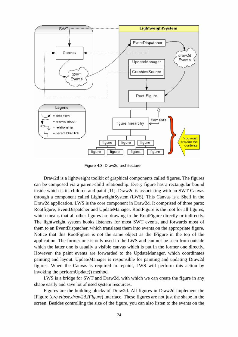
Figure 4.3: Draw2d architecture
Draw2d is a lightweight toolkit of graphical components called figures. The figures can be composed via a parent-child relationship. Every figure has a rectangular bound inside which is its children and paint [11]. Draw2d is associating with an SWT Canvas through a component called LightweightSystem (LWS). This Canvas is a Shell in the Draw2d application. LWS is the core component in Draw2d. It comprised of three parts: Rootfigure, EventDispatcher and UpdateManager. RootFigure is the root for all figures, which means that all other figures are drawing in the RootFigure directly or indirectly. The lightweight system hooks listeners for most SWT events, and forwards most of them to an EventDispatcher, which translates them into events on the appropriate figure. Notice that this RootFigure is not the same object as the IFigure in the top of the application. The former one is only used in the LWS and can not be seen from outside which the latter one is usually a visible canvas which is put in the former one directly. However, the paint events are forwarded to the UpdateManager, which coordinates painting and layout. UpdateManager is responsible for painting and updating Draw2d figures. When the Canvas is required to repaint, LWS will perform this action by invoking the performUpdate() method.
LWS is a bridge for SWT and Draw2d, with which we can create the figure in any shape easily and save lot of used system resources.
Figures are the building blocks of Draw2d. All figures in Draw2d implement the IFigure (org.elipse.draw2d.IFigure) interface. These figures are not just the shape in the screen. Besides controlling the size of the figure, you can also listen to the events on the
24

figure include mouse events and modification of the figure structure, set the shape of mouse curse, focus on or transparent the figure, and so on.
Draw2d provides three kinds of default figures: Shape, Widget and Layer. Shape contains rectangle, triangle, ellipse, and so on. Widget contains label, button, and scrollbar, and so on. Layer has the capability to support the zoom and scroll functions for the figures inside it.
Every figure has a Border. The type of border in Draw2d contains GroupBoxBorder, TltleBarBorder, FrameBorder, FocusBorder, LineBorder, MarginBorder, ButtonBorder, SimpleLoweredBorder, SimpleRaisedBorder and CompoundBorder which can compound two kinds of borders. In addition, there is an Insets class in Draw2d to represent the location of border in the figure. Figure 4.4 from [12] shows an example of some of these border types.
Figure 4.4: Draw2d border types
A figure can have lots of subfigures. These subfigures should be displayed with a suitable layout to avoid overlaps. The LayoutManager is used to solve this problem by managing the position and size of a figure’s child figures. Similarly, Draw2d provides some LayoutManager which can be used directly. For example, FlowLayout is to layout a figure’s children into the table alignment; XYLayout is to let user change the location of figure; DelegatingLayout is to delegate the layout of a figure’s child figures to the child figure’s locators. You also can make your own layout.
Another import task for the figures in the graphical application is adding connections. ConnectionAnchor is used to define the source and target endpoints of a connection. ConnectionRouter is used to set the endpoints and other points on the connection. There are lots of connections with different appearance as in the UML class diagram or in the program flow chart. To solve this problem, Draw2d provides three elements (Router, Anchor and Locator) to perform different connection patterns. Router is responsible for the appearance and operations of the connections. The default connection pattern with no router is straight line. Figure 4.5 shows three connection patterns with different router. [16]
25

Figure 4.5: Three connection patterns with different router
An anchor is a fixed or calculated location associated with some figure. For
example, the ChopboxAnchor is first suppose the center point to be the connection point, then calculating the point where the connection would intersect the figure to be the endpoint. Figure 4.6 from [11] shows a ChopboxAnchor calculates the connection endpoint by finding the intersection with a rectangle. Other available anchors include EllipseAnchor, LabelAnchor and XYAnchor.
Figure 4.6: A ChopboxAnchor calculates the connection endpoint
At last, Locator is used to locate the figures. For example, MidpointLocator is used to place figures at the midpoint of a connection; ArrowLocator can be used to position decorations on the end of connections; BendpointerLocator can be used to position bendpoint handles on a connection and ConnectionEndpointLocator is used to locate a figure near either the start or end of a connection. For more information about Draw2d framework see [11,12,13].
4.2.2 GEF
Draw2d focused on the painting and layout of figures for GEF framework. After introducing the Draw2d framework, we shall describe the GEF framework. Figure 4.7 shows the GEF architecture [17]. Figure 4.8 shows a high-level view of GEF [11].
26

Figure 4.7: GEF architecture
Figure 4.8: A high-level view of GEF
As we said before, the GEF framework is based on the MVC design. It provides the link (controller) between an application’s model and view. The controller is responsible for maintaining the view, interpreting UI events and updating the model according to these events. GEF also provides input handlers include tools and actions that turn events into requests. Requests and Commands are used to encapsulate interactions and the effects on the model.
27

Model The model in GEF just contacts with controller. It knows nothing about the view. In order to notify the changes of the model to the controller, the model must register controller as event listeners in it to catch these events. It must fire related events to the controller when it changes. Then controller is responsible for notifying the view to update.
Controller As we know, controller is the bridge for the model and view in the MVC structure. It is also central elements in GEF applications. It not only needs to listen in the changes on the model, but also has to reflect the editing result on the model when user edits the view. For example, when user deletes a table on the database structure diagram, controller has to delete this table object, the field object in the table and all related connections on these objects. The controller in GEF is called an EditPart. It is comprised of a group of Editpart object. Every model object is corresponding to an EditPart object. It should have an EditPartFactory object responsible for creating the corresponding EditPart object based on the given model object in your application. Then this EditPartFactory can be used by the view. Figure 4.9 shows an EditPart object [17].
Figure 4.9: EditPart object
RootEditPart is a special EditPart. It has no relationship with your model. It is used to associate EditPartViewer with contents which are the top EditPart in your application. It can be seen as a container for the contents. There is a setRootEditPart() method in EditPartViewer to assign the corresponding RootEditPart of the view in particular.
The user’s editing operation is converted to a series of request. Requests are the communication objects used in the GEF. There are lots of types of requests. These types are called Role in GEF. GEF contains two kinds of roles: graphical and non-graphical. For example, Layout Role is a graphical role corresponding to the related operation of the layout. And Connection Role is a non-graphical role corresponding to the related operation of the connections. Role is performed by EditPolicy. The main function of EditPolicy is creating the related command based on the request. Then the command
28

will operate the model object directly. For every EditPart, you can install some EditPolicies. The user’s operations of this EditPart will be handed in to corresponding EditPolicy which will process these operations. Thus, the user can share some repeat operations among different EditParts. For more details about the EditPolicy, Role and Request can be found in [11, 12].
View GEF provides two viewer types: graphicalViewer and treeViewer. The graphicalViewer use Draw2d IFigure to manifest. It is often used in the editor. The treeViewer is used to perform the outline view.
GEF uses EditPartViewer as its view. The function is similar to the JFace viewer. And EditPart is like its contentProvider and LableProvider that can be set by setContents() method. The most used Editor is a GraphicalEditorWithPalette (the Editor provided by GEF is a subclass of EditorPart, containing a graphical edit area and a toolbar). This Editor uses two view classes: GraphicalEditViewer and PaletteViewer. PalerreViewer is also subclass of GraphicalEditViewer. Developer should customize the EditPartViewer in the configureGraphicalViewer() and initializeGraphicalViewer() method, including assign its contents and EditPartFactory. EditPartViewer is also ISelectionProvider at the same time. Thus, user can do selection in the editor and the registered SelectionChangeListener can receive the selected events. EditPartViewer will maintain the selected states in every EditPart. If there is no EditPart been selected, the default selection is to be the EditPart of contents.
That is an overview about the implementation of the MVC structure in GEF. Now we will give a short description about how the GEF application works. It works as follows: EditPartViewer receives the user’s operations, such as selecting node, adding node or deleting node. Every node corresponds to an EditPart object, this object contains a group of EditPolicy classified by the operation Role. Every EditPolicy is corresponding to some Command objects. These commands will modify the model at last. The user’s operations are converted to Request assigned to the appropriate EditPolicy. Then the EditPolicy create appropriate Commands to modify the model. These Commands will be saved in EditDomain’s command stack to perform the redo / undo functions. EditDomain is specially used to maintain the objects of EditPartViewer and Command. Generally every Editor corresponds to a unique of these objects. Figure 4.10 from [12] shows an example of the communication chain.
29
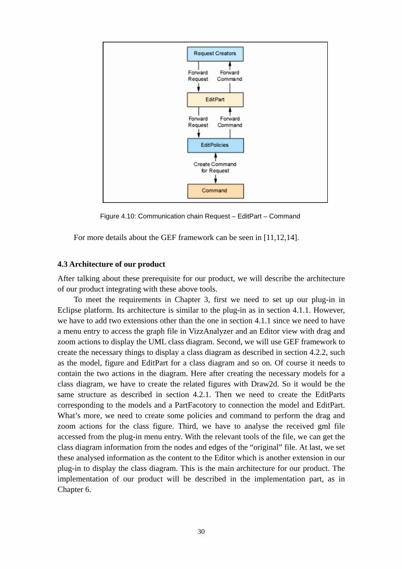
Figure 4.10: Communication chain Request – EditPart – Command
For more details about the GEF framework can be seen in [11,12,14].
4.3 Architecture of our product
After talking about these prerequisite for our product, we will describe the architecture of our product integrating with these above tools.
To meet the requirements in Chapter 3, first we need to set up our plug-in in Eclipse platform. Its architecture is similar to the plug-in as in section 4.1.1. However, we have to add two extensions other than the one in section 4.1.1 since we need to have a menu entry to access the graph file in VizzAnalyzer and an Editor view with drag and zoom actions to display the UML class diagram. Second, we will use GEF framework to create the necessary things to display a class diagram as described in section 4.2.2, such as the model, figure and EditPart for a class diagram and so on. Of course it needs to contain the two actions in the diagram. Here after creating the necessary models for a class diagram, we have to create the related figures with Draw2d. So it would be the same structure as described in section 4.2.1. Then we need to create the EditParts corresponding to the models and a PartFacotory to connection the model and EditPart. What’s more, we need to create some policies and command to perform the drag and zoom actions for the class figure. Third, we have to analyse the received gml file accessed from the plug-in menu entry. With the relevant tools of the file, we can get the class diagram information from the nodes and edges of the “original” file. At last, we set these analysed information as the content to the Editor which is another extension in our plug-in to display the class diagram. This is the main architecture for our product. The implementation of our product will be described in the implementation part, as in Chapter 6.
30

5 Design and implementation
After describing the architecture for Eclipse plug-in, Draw2d and GEF framework in the previous chapter, we will explain in the following sections the design and implementation of our product using these techniques.
5.1 Prerequisites
First, we should have the latest Eclipse version, JDK 1.5, GEF framework includes Draw2d installed. You can download Eclipse from www.eclipse.org and unzip it to where you want to have it, download JDK 1.5 from www.sun.com/java.
There are two ways to install GEF. The first one is download the version of GEF that matches your installation of Eclipse. Then shut off the Eclipse and unzip the download GEF SDK into the “eclipse” directory’s parent directory. At last, restart Eclipse and verify everything is installed. Go to Help About Eclipse Platform Plug-in Details, it should have these providers and plug-in names: Eclipse.org Draw2d; Eclipse.org Draw2d Documentation (SDK only); Eclipse.org Graphical Editing Framework; Eclipse.org Graphical Editing Framework Documentation (SDK only); Eclipse.org Graphical Editing Framework SDK (SDK only).
Your eclipse/plugins directory should contains these directories: (Note: version number may differ according to download): org.eclipse.draw2d.doc.isv_3.2.0 (SDK only); org.eclipse.draw2d_3.2.0; org.eclipse.gef.doc.isv_3.2.0 (SDK only); org.eclipse.gef.source_3.2.0 (SDK only); org.eclipse.gef_3.2.0. Your eclipse/features directory should contains these directories: (Note: Version numbers may differ according to download): org.eclipse.gef.source_3.2.0 (SDK only) org.eclipse.gef_3.2.0.
The second way is to use the Eclipse update manager. First go to the Help/Software Updates/Find and install…, then choose the “Search for new features to install” option, at last, add the update site: http://download.eclipse.org/tools/gef/update-site/releases/site.xml and click “Finish” button to implement the updating.
They are all written in Java and should run on all operating systems supported by the Eclipse platform. What we use is Windows XP. [15]
5.2 Plug-in
Now, we first have to build a plug-in project in Eclipse. Go to File New Project, choose “Plug-in Project”. Then input the project name, what we set is UMLClassDiagram. Others use default configuration. Then we have an empty plug-in project named UMLClassDiagram. Second, we need to add the necessary plug-ins that depended by our product to this plug-in project. In the dependencies page, add the following plug-ins: org.eclipse.ui; org.eclipse.core.runtime; org.eclipse.gef; org.eclipse.ui.views; org.eclipse.core.resources; org.eclipse.ui.ide. Third, we have to add extensions to our plug-in project. We have depicted the purpose and usage of the dependencies and extension in the architecture section, so I will not describe it again. To
31
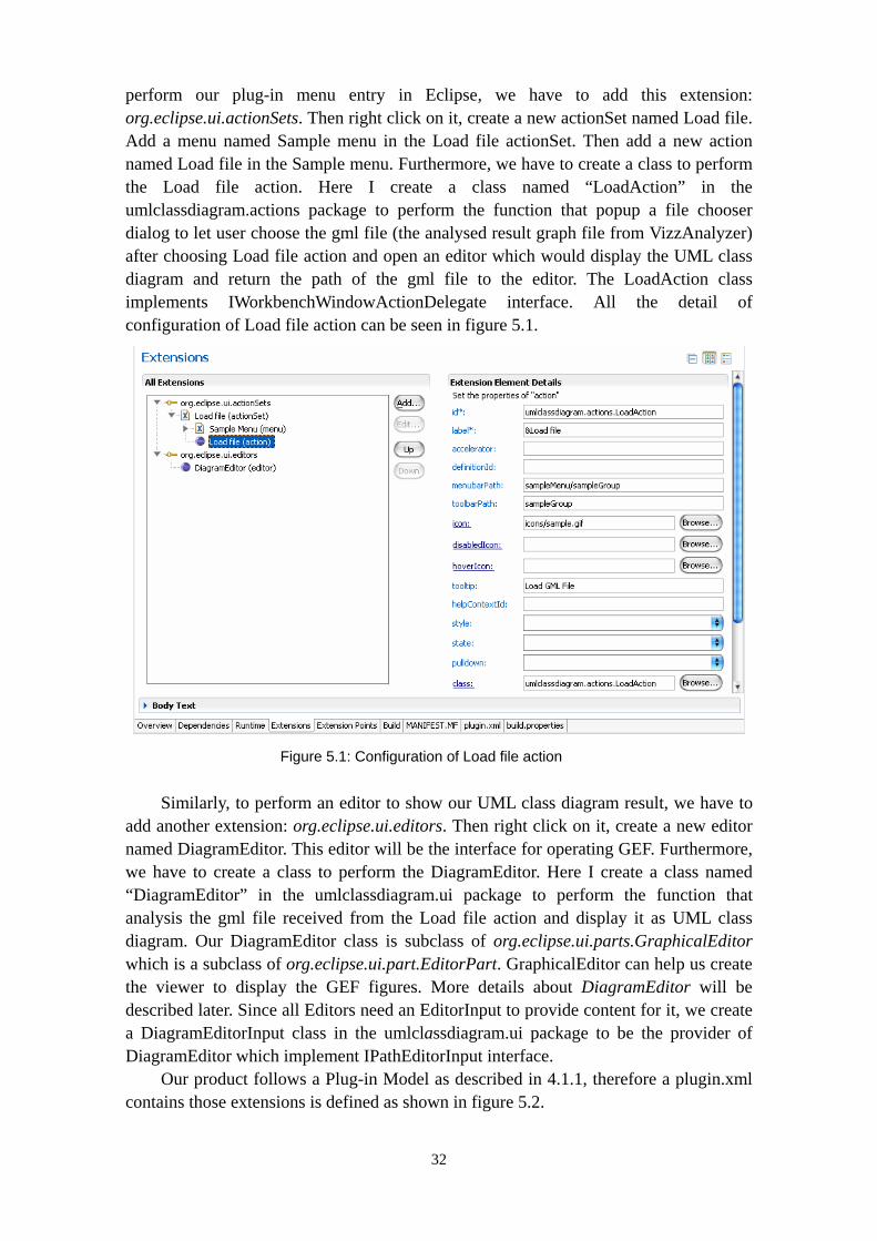
perform our plug-in menu entry in Eclipse, we have to add this extension: org.eclipse.ui.actionSets. Then right click on it, create a new actionSet named Load file. Add a menu named Sample menu in the Load file actionSet. Then add a new action named Load file in the Sample menu. Furthermore, we have to create a class to perform the Load file action. Here I create a class named “LoadAction” in the umlclassdiagram.actions package to perform the function that popup a file chooser dialog to let user choose the gml file (the analysed result graph file from VizzAnalyzer) after choosing Load file action and open an editor which would display the UML class diagram and return the path of the gml file to the editor. The LoadAction class implements IWorkbenchWindowActionDelegate interface. All the detail of configuration of Load file action can be seen in figure 5.1.
Figure 5.1: Configuration of Load file action
Similarly, to perform an editor to show our UML class diagram result, we have to add another extension: org.eclipse.ui.editors. Then right click on it, create a new editor named DiagramEditor. This editor will be the interface for operating GEF. Furthermore, we have to create a class to perform the DiagramEditor. Here I create a class named “DiagramEditor” in the umlclassdiagram.ui package to perform the function that analysis the gml file received from the Load file action and display it as UML class diagram. Our DiagramEditor class is subclass of org.eclipse.ui.parts.GraphicalEditor which is a subclass of org.eclipse.ui.part.EditorPart. GraphicalEditor can help us create the viewer to display the GEF figures. More details about DiagramEditor will be described later. Since all Editors need an EditorInput to provide content for it, we create a DiagramEditorInput class in the umlclassdiagram.ui package to be the provider of DiagramEditor which implement IPathEditorInput interface.
Our product follows a Plug-in Model as described in 4.1.1, therefore a plugin.xml contains those extensions is defined as shown in figure 5.2.
32

<?xml version="1.0" encoding="UTF-8"?>
<?eclipse version="3.2"?>
<plugin>
<extension
point="org.eclipse.ui.actionSets">
<actionSet
label="Load file"
visible="true"
id="UMLClassDiagram.actionSet">
<menu
label="Sample &Menu"
id="sampleMenu">
</menu>
<action
label="&Load file"
icon="icons/sample.gif"
class="umlclassdiagram.actions.LoadAction"
tooltip="Load GML File"
menubarPath="sampleMenu/sampleGroup"
toolbarPath="sampleGroup"
id="umlclassdiagram.actions.LoadAction">
</action>
</actionSet>
</extension>
<extension
point="org.eclipse.ui.editors">
<editor
class="umlclassdiagram.ui.DiagramEditor"
default="false"
icon="icons/sample.gif"
id="UMLClassDiagram.ui.DiagramEditor"
name="DiagramEditor"/>
</extension>
</plugin>
Figure 5.2: UMLClassDiagram plugin.xml
5.3 GEF
After creating the plug-in, we shall introduce how to use GEF to implement our main function. That means we need to draw the class diagram on Diagram Editor.
We have described how GEF works in the previous section. Here the basic process is as follows:
First, create the models, such as Diagram model, class model, attribute model, method model and connection model and so on.
33

Second, create the figures for the model using Draw2d, such as class figure and connection figure and so on.
Third, create the EditParts corresponds to the models, such as DiagramPart, ClassPart and so on.
Fourth, create the PartFactory to associate the model and EditPart. Finally, create Graphicalviewer in the Editor to display the UML class diagram. Of course, we have to set the gml file as input and analysis it to display in the
Editor, also we have to add drag and zoom actions to the figures in the class diagram. These will be explained later. Now we are focusing on displaying class diagram using GEF framework. So we follow the basic process above.
5.3.1 Model
First we create the models for class diagram and put them in the umlclassdiagram.model package. Figure 5.3 shows the model class diagram. Since these models are for a class diagram, they must at least have a representation of the following elements:
Class; it should contain the class name, its attributes, its methods and a list of connections with different relations.
Attribute; it should contain these properties: the identifier, the type and visibility.
Method; it should contain these properties: the identifier, the type, visibility and its parameters.
Connections; they are representing the different relationships between every two classes. Each connection should contain a source class and a target class. The relationships include association, composition, and inheritance and so on. For more details about the class diagram has already been introduced in the UML 2.0 part in section 2. I will not give more description about it.
To implement these models, each model needs a class to represent it. In order to perform the drag and zoom actions on a class figure, we use the mechanism of notification specific to the java beans. For example, a class of model having to notify will have each one object java.beans.PropertyChangeSupport which includes the list of listeners; a class having to listen to the notifications will implement java.beans.PropertyChangeListener.
34

Figure 5.3: Model class diagram
In Figure 5.3, we are not following the models described above exactly, because the reason of GEF. It will be explained in the EditParts. Now I will explain how our models be organized. The Element is an abstract class to provide a support for the notification of the events. It has a data member of the java.beans.PropertyChangeSupport type which encapsulates the list of the listeners, three methods: addPropertyChangeListener(java.beans.PropertyChangeListener) and removePropertyChangeListener(java.beans.PropertyChangeListener) to add and remove listeners in the occurrence EditPart associated with the object; firePropertyChange(java.beans.PropertyChangeListener) to fire changes of the model to listeners. In GEF, the listener of the model is its EditPart. We will set it to be a listener registered in the model in the method active() in the EditPart. A list of data members public static final String are used to define the various properties prone to notification. For example, the member public static final String PROP_LOCATION = “LOCATION” in the Node class is to define the location of the node whose location can be changed by drag action in the Editor. The class Diagram that extends the Element class is used to store the whole information of all figures. It is served as a container with the models. In this case a class representing the diagram will have the list of the classes of the models as a data member. Node that extends the Element class represents an element of the
35

diagram which has a data member forced determining its position and size in the diagram. It also contains a name to represent its name, the inputs and outputs lists to represent the incoming and outgoing connections on it. The class model thus derives from Node. Since the class is a key word in java programming language, we use Subject to replace it to avoiding this confliction. So you can see in figure 15, the Subject extends Node class. It inherits all the properties of Node. In addition, it adds its own properties: an attibuteList which contains all the attributes of the class and a methodList which contains all the methods of the class. Additionally, we add a ListModel class to be the super class for AttributeList and MethodList. In the ListModel, it contains an elementList list used to add, remove or get the elements. Then the AttributeList and MethodList extend the ListModel class. In AttributeList, it is used to deal with the attributes as well s the MethodList is used to deal with the methods. The Attribute class represents the attribute model. It contains these attributes: id, identifier, type and visibility. The characters represent their means. Note that the id is a unique identifier of the attribute differing from others. Similarly, the Method has the properties: id, identifier, return type, visibility and its parameters. For the relations among classes, we create a class for each kind of relation. Here we have association, composition and inheritance. Every relation has a source node and target node.
5.3.2 Figure
After creating the models for a class diagram, now we shall create figures for each model. We put the figures in umlclassdiagram.figures package. Figure 5.5 shows the figure class diagram.
In GEF, the code of the figures is completely independent of the model. A figure does not have any reference towards the model which it represents. Thus the figures must save the various properties of the model which are to be represented in data members and provide methods to make it possible to adjust them.
It is pretty to add small images in the figures. We set some images for the visibility of the attributes and methods to replace the default “+”and “-” in the UML class diagram. We put the images into the umlclassdiagram.figures package. The AttributeFigure and MethodFigure will use these images. org.eclipse.swt.graphics need to be imported in these classes. Figure 5.4 is an example of statement used to create an image for the PUBLIC visibility of an attribute. So then one can paint it using a Graphics object in the method Paint of a figure.
Figure 5.4: An example for creating an image
36

Figure 5.5: Figure Class Diagram
In Figure 5.5, the method and attribute figure is represented by class MethodFigure and AttributeFigure extend org.eclipse.draw2d.Label. The method getVisibilityIcon(int visibility) is to get the image for the visibility icons. The icon depends on the visibility of the method/attribute. The icon is an image as describes above. Figure 5.6 shows some of the icons.
Figure 5.6: Some of the visibility icons
The icon in green represents the visibility of public, in red represents the visibility of private and in yellow represents the visibility of protected. The method setSignature in both of the method figure and attribute figure class is to adjust the signature of the method or the declaration of the attribute to the properties of the Label. The method
37
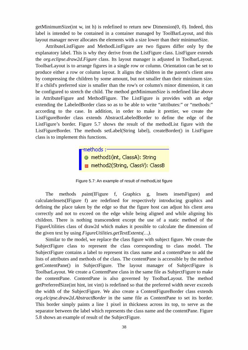
getMinimumSize(int w, int h) is redefined to return new Dimension(0, 0). Indeed, this label is intended to be contained in a container managed by ToolBarLayout, and this layout manager never allocates the elements with a size lower than their minimunSize.
AttributeListFigure and MethodListFigure are two figures differ only by the explanatory label. This is why they derive from the ListFigure class. ListFigure extends the org.eclipse.draw2d.Figure class. Its layout manager is adjusted in ToolbarLayout. ToolbarLayout is to arrange figures in a single row or column. Orientation can be set to produce either a row or column layout. It aligns the children in the parent's client area by compressing the children by some amount, but not smaller than their minimum size. If a child's preferred size is smaller than the row's or column's minor dimension, it can be configured to stretch the child. The method getMinimumSize is redefined like above in AttributeFigure and MethodFigure. The ListFigure is provides with an edge extending the LabeledBorder class so as to be able to write “attributes:” or “methods:” according to the case. In addition, in order to make it prettier, we create the ListFigureBorder class extends AbstractLabeledBorder to define the edge of the ListFigure’s border. Figure 5.7 shows the result of the methodList figure with the ListFigureBorder. The methods setLabel(String label), createBorder() in ListFigure class is to implement this functions.
Figure 5.7: An example of result of methodList figure
The methods paint(IFigure f, Graphics g, Insets insetsFigure) and calculateInsets(IFigure f) are redefined for respectively introducing graphics and defining the place taken by the edge so that the figure host can adjust his client area correctly and not to exceed on the edge while being aligned and while aligning his children. There is nothing transcendent except the use of a static method of the FigureUtilities class of draw2d which makes it possible to calculate the dimension of the given text by using FigureUtilities.getTextExtents(…).
Similar to the model, we replace the class figure with subject figure. We create the SubjectFigure class to represent the class corresponding to class model. The SubjectFigure contains a label to represent its class name and a contentPane to add the lists of attributes and methods of the class. The contentPane is accessible by the method getContentPane() in SubjectFigure. The layout manager of SubjectFigure is ToolbarLayout. We create a ContentPane class in the same file as SubjectFigure to make the contentPane. ContentPane is also governed by ToolbarLayout. The method getPreferredSize(int hint, int vint) is redefined so that the preferred width never exceeds the width of the SubjectFigure. We also create a ContentFigureBorder class extends org.elcipse.draw2d.AbstractBorder in the same file as ContentPane to set its border. This border simply paints a line 1 pixel in thickness across its top, to serve as the separator between the label which represents the class name and the contentPane. Figure 5.8 shows an example of result of the SubjectFigure.
38

Figure 5.8: An example of result of the SubjectFigure
5.3.3 EditParts
Now we create the EditParts corresponding to the models to bridge the model and figure. We put them into the umlclassdiagram.parts package. Figure 5.9 shows the EditPart class model.
Figure 5.9: EditPart class diagram
39

As in Figure 5.9, the EditPart almost follow the same hierarchy as the model and figure. All EditParts extend the AbstractGraphicalEditPart class which is particularized for the draw2d figures. There are two abstract methods to implement:
IFigure createFigure(): return the figure associated with the model with this EditPart. The return result is an object of IFigure. Usually it is the figures in umlclassdiagram.figures package. However, here we create the Diagram figure and relation figure in this method for the DiagramPart and different kinds of relation EditPart, such as associationPart and so on. The figure corresponding to Diagram model is a figure with FreeformLayer in GEF. It is a layer that allows the user to extend it in all 4 directions. For the figures of the relations, it is a line called PolylineConnection in GEF used to connect two classes in default. We add different decorations, for example an arrow, on the line by the method setTargetDecoration() to represent different kinds of relations.
Void createEditPolicies(): install different EditPolicies from this EditPart. If there is no need to have any actions on a model, its EditPart can have nothing in this method. For example, we need to add drag and zoom actions on the class figure, so we need to create the corresponding policies and install in this method in the right EditPart. This will be described in the drag and zoom action part.
Other methods are to be redefined:
List getModelChildren(): called by GEF to obtain the list of the objects of the model which are regarded as the children of the model of current EditPart. For the EditPart which represent parent objects in parent-child relationships need to override this method. For our program, this method in DiagramPart returns the Diagram model object which contains a list of Subject model object. In the SubjectPart, it returns a list contains its attributeList and methodList. Similarly, in the AttributeListPart it returns the list of attributes belong to the class who have this attributeList as well as in the MethodLIstPart it returns the list of methods.
IFigure getContentPane(): if the parent EditPart’s figure is not the direct parent of the child EditPart’s figure, as the case for SubjectPart which has a attributeList and methodList contains the class attributes and methods, one will need to override this method. The content pane is the containing figure into which GEF adds figures created by child EditParts, which is by default the figure returned by the EditPart’s createFigure() method. What’s more, we encounter a problem here using the original class models. Because we need to have the class figure separated for the attributes and methods. The attributes and methods must be represented graphically inside their class. But we wish to be able to separate the methods and attributes and not to gather them together in the same visual container. However, GEF does not make it possible to define several content panes for an Editpart. To solve this problem, we define an attributeList EditPart and a methodList EditPart on the content pane. They are used to contain the attributes and methods respectively. So that is why and how our current class models come.
40

Void refreshVisuals(): this method is called by GEF when it is necessary to synchronize graphics of the figure of EditPart with the model of EditPart. It is called first once before the posting of the figure of EditPart. In our program it is necessary to adjust the properties of the figure according to the model and if required to tell the parent part (here is DiagramPart) that this part and its figure are to be constrained to the given constraint.
With these five methods, it is sufficient to post a model without connections. But in our program, we also have the following methods since we need the connections to represent the relations among classes.
Void activate(): called when EditPart belongs to a tree structure of EditPart visualized in a viewer. It is necessary to register the EditPart as a listener of its model.
Void deactivate(): opposite to activate() method, it is to remove the listener. Void propertyChanged(PropertyChangeEvent evt): to react to the notification
of the model. This method could simply call refreshVisuals() method or be more selective in the update according to the event.
The model objects which may participate in connections, as the case of NodePart in our program, must also implement a number of additional methods defined in the interface NodeEditPart.
List getModelSourceConnections(): this returns all the connection model objects for which the node model object is the source.
List getModelTargetConnections(): this works identically to the last method, except that it returns the relationship objects for which the node model object is the target.
getSourceConnectionAnchor and getTargetConnectionAnchor: these methods return objects which represent the points to which connections between nodes can be attached. The NodeConnectionAnchor class is used to represent the point.
5.3.4 PartFactory
Now we have the model, view and controller. Left open is, how we associate them. GEF provides the PartFactory to solve this problem. There are only two steps to perform this action in the PartFactory.
1. Create the right controller according to the given model. 2. Use setModel() method to connect the model and its controller.
5.3.5 Create GraphicalView
Now, we need to create a view to display the figures of class diagram. We create the view in DiagramEditor. In GraphicalViewer there are two methods: configuregGraphicalViewer() and initializeGraphicalViewer() to configure and initialize GraphicalViewer respectively. Configure the GraphicalViewer includes choose the suitable RootEditPart which define the workaround of the editor and EditPartFactory.
41

GEF contains zoomable and scrollable workaround of RootEditPart. The EditPartFactory in our program is the PartFactory. Thus, configure the GraphicalViewer is to connect the model and its controller in the GraphicalViewer. After configuring the GraphicalViewer, we can set the content of GraphicalViewer. To perform this, we use the setContents() method in the initializeGraphicalViewer() method. In our program the content is a diagram contains the class diagram information of the gml file. Another important thing needs to be noted is that we have to set an Editing domain to store the Command Stack in GEF. Editing domain is also used to notify the SWT events generated in Graphicalviewer. So we use the setEditDomain() method to set an org.elipse.gef.DefaultEditDomain as the Editing domain in the constructor of DiagramEditor class. In GEF an Editing domain must be set as Graphicalviewer, which means can draw figures on it, but our DiagramEditor is derived from GraphicalEditor, so here the default Editing domain – DefaultEditDomain is defined as Graphicalviewer. Figure 5.11 shows the codes of the three methods in our DiagramEditor. After this, the editor is able to display the class diagram.
Figure 5.10: Code of the PartFactory
Note that when putting the GraphicalViewer in an Editor, we use DefaultEditDomain, while when putting the GraphicalViewer in a View or in a standalone Eclipse application, we should use org.eclipse.gef.EditDomain as the Editing domain.
42

Figure 5.11: Three methods in DiagramEditor
5.4 Drag and Zoom actions
Now we will add the drag and zoom actions for the class figure of a class diagram. This will refer to the Policy, Command and Role in GEF. When a model changes, as the case we change the location or size of the Subject (represent the class in class diagram), it will generate the Requests (org.eclipse.gef.Reauest). Then the requests will be send to the EditPart corresponding to the model. The related Editing Policy should be installed in the EditPart. The Editing Policy is used to manage some Command which is to perform those requests. Figure 5.12 shows this process.
Generate Request
Org.eclipse.gef.Request Perform
Send to
Register
Manage
Install
Model changes
EditPart Editing Policy
Command
Figure 5.12: Process of the drag and zoom actions
First, we create a CustomXYLayoutEditPolicy in umlclassdiagram.policies package extends org.eclipse.gef.editpolicies.XYLayoutEditPolicy.
Second, we install the editing policy in DiagramPart. Since the DiagramPart uses FreeformLayout, so we can install the CustomXYLayoutEditPolicy in the createEditPolicies() method in DiagramPart. The code is: installEditPolicy(EditPolicy.LATOUT_ROLE, new CustomXYLayoutEditPolicy()); The first parameter in the method is a string which defined the Role of the installed editing
43

policy. Here we use a constant of the EditPolicy to represent the role of this editing policy. After installing the CustomXYLayoutEditPolicy, we can choose the handler of the figure.
Third, we need to create Command. Though we change the size and location of the figure is two requests, they are all related with the figure constraint. So we just create a ChangeConstaintCommand class in umlclassdiagram.commands package to change the constraint.
Fourth, after creating the command, it will perform the command in the Editing Policy framework by the method createChangeConstraintCommand(EditPart child, Object constraint) method.
Fifth, after finishing the above works, we still can not change the size or location of the figure. We need to listen to the model changes and notify to refresh the view. So we invoke the firePropertyChange() method in the setSize() and setLocation() methods in Node model to fire the changes of the Subject model. Then the EditPart corresponds to its model is registered as a listener as described in the Model and EditPart part. After all these steps finished, the drag and zoom actions is able to work now.
5.5 Analysis of the gml file
The last thing we need to do for our program is to analyse the gml file and create actual UML class diagrams. Since we already can load the gml from the Eclipse menu entry, we need to analysis this file to the UML class diagram information and set its result to the content of the GraphicalViewer to display. The method setInput(IEditorInput input) in DiagramEditor is to perform this function. In order to analysis the received gml file, we create a readFile(String path) method to analysis the file. This method returns a Diagram model which contains all the figures of a class diagram. Before analysis the gml file, we need to add the Grail-bin-1.9.45-200702061443.jar file to the Java Build Path of our plug-in project. In addition, we add the CommonMetaModel10.java file in the same package as DiagramEditor.java file. The grail and CommonMetalModel file provided by the author of VizzAnalyzer are used to help reading information from the gml file including the node and edge information. The parameter in the method readFile(String path) is the location of the gml file in the computer.
The gml file contains node and edge information. Node is used to define the properties of the class diagram. Such as defining if the node is a class, an attribute or a method. Edge is used to define the relations among the nodes. For example, an attribute node belongs to a class node or the relationship between two class nodes. Table 5.1 shows the properties of the node which will be used in our program and their usage. Table 5.2 shows the properties of the edge which will be used in our program and their usage.
44
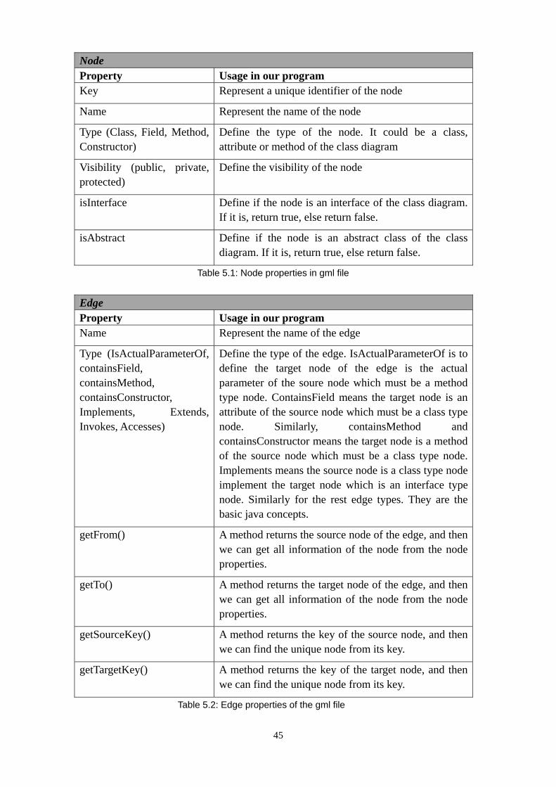
Node Property Usage in our program Key Represent a unique identifier of the node
Name Represent the name of the node
Type (Class, Field, Method, Constructor)
Define the type of the node. It could be a class, attribute or method of the class diagram
Visibility (public, private, protected)
Define the visibility of the node
isInterface Define if the node is an interface of the class diagram. If it is, return true, else return false.
isAbstract Define if the node is an abstract class of the class diagram. If it is, return true, else return false.
Table 5.1: Node properties in gml file Edge Property Usage in our program Name Represent the name of the edge
Type (IsActualParameterOf, containsField, containsMethod, containsConstructor, Implements, Extends, Invokes, Accesses)
Define the type of the edge. IsActualParameterOf is to define the target node of the edge is the actual parameter of the soure node which must be a method type node. ContainsField means the target node is an attribute of the source node which must be a class type node. Similarly, containsMethod and containsConstructor means the target node is a method of the source node which must be a class type node. Implements means the source node is a class type node implement the target node which is an interface type node. Similarly for the rest edge types. They are the basic java concepts.
getFrom() A method returns the source node of the edge, and then we can get all information of the node from the node properties.
getTo() A method returns the target node of the edge, and then we can get all information of the node from the node properties.
getSourceKey() A method returns the key of the source node, and then we can find the unique node from its key.
getTargetKey() A method returns the key of the target node, and then we can find the unique node from its key.
Table 5.2: Edge properties of the gml file
45

From this information, we can define different types of models in class diagram according to the types of the node. Furthermore, we define the relations among the models based on the edge information. For example, we can define that which attribute node and method node belong to which class node, or the different relations between two class models so that we create different kinds of relation models, such as association and inheritance, and so on. After creating these models, with the GEF mechanism, the PartFactory define the right EditPart for the model, and then create its figure. With this information as the content of the GraphicalViewer, we can have the class diagram of the gml file displayed in the Editor. Of course with the drag and zoom action on the figures. Figure 5.13 shows an example of the class diagram of a gml file after dragging the class figures to a suitable place to have a pretty look and feel.
Figure 5.13: An example of the class diagram of a gml file
46
6 Conclusion and Future work
This last chapter summarizes the result of the thesis. It shows how the problem described in the introduction has been solved and if all the goals have been met. In addition, it discusses how to improve the result of the thesis and the direction of future developments.
6.1 Conclusions
The problem addressed by this thesis is an extending task as described in the problem description part in the introduction section: use the existing framework to write a visualization plug-in connecting Eclipse UML2 to the VizzAnalyzer by analysing the graph information stored in the VizzAnalyzer and viewing them as UML class diagram. The solution for solving this problem is based on the Eclipse platform, its extensive architecture and developing a new plug-in utilizing GEF to read the original graph file with API of VizzAnalyzer and viewing the file as UML class diagram by the MVC architecture of the GEF framework.
We described the goals and appropriate criteria for solving the problem in section 1.3. The final result of our work can be seen in figure 5.13.
The first goal is to get a well understanding of the UML 2.0 class diagram. This goal was met by learning UML 2.0 technology as described in Chapter 2.2. After getting this information, it helps us to design the models for class diagram in GEF and define their relations as the case described in the GEF model part in the Design and Implementation section. Table 2.1 and table 2.2 contain the details of the UML technology.
The second goal was to analyse the original graph file from the VizzAnalyzer to get the necessary information for viewing them as UML class diagram. This goal was met by having a good understanding of the Grail API and the CommonMetalModel10.java file provided by the author of VizzAnalyzer to get the node and edge information from the gml file as described in the Analysis gml file part in the Design and Implementation section. With the UML 2.0 class diagram knowledge, it is possible to make the different models for UML class diagram. Furthermore this can be used by GEF framework to viewing them as the class diagram. Table 5.1 and table 5.2 in Chapter 5 shows the details of the useful gml file information.
The third goal is to design and implement a plug-in for Eclipse to perform our extending functions for VizzAnalyzer. The plug-in contains a Load file menu entry to open a file choose dialog to allow user to load the original graph file and return the path of it. The solution meeting these criteria has been implemented in the plug-in design part in the Design and Implementation section. For a better understanding of the requirements, a use case analysis was performed in Chapter 3. And more detail about the plug-in has been introduced in Chapter 4.1.1. These provide a great help for our plug-in’s designing and implementing as described in Chapter 5. After having the plug-in, we are able to show the UML class diagram with GEF in it.
The fourth goal is the pivotal one, and also the most complicate among all these goals. It is to show the UML class diagram by using the GEF framework with which we
47

need to create models, figures and the corresponding EditParts of the class diagram based on the MVC architecture. In addition, we add the drag and zoom actions on the class figures of the class diagram to get a clearer looking of them. And an appropriate layout algorithm also needs to be designed to avoid overlaps on the figures of the class diagram. The solution meeting these criteria has been implemented and its design been discussed in the GEF part in the Design and Implementation section. Figure 5.3, 5.5, 5.9 in Chapter 5 shows an overview of the class of design and implementation. Additionally, its architecture was described in the Draw2d and GEF architecture part in Section 4, on which the design and implementation are based on. Figure 5.13 in Chapter 5 represents the outcome of this design and implementation.
6.2 Future work
The UMLClassDiagram plug-in basically serves its purpose. In order to fulfill all the requirements of the functions and improve our outcome, we should still focus on the following things.
The model and figure of the class diagram is not complete until now. For the attribute and method model, it still misses the return type as well as the parameters in the method since the gml file missing this information until now. This should be done when the original graph includes this information. Furthermore it should update its figure corresponds to model.
More relations between two class figures need to be designed and implemented to have the completely class diagram. Since the type of attribute is still missing, it still misses some kinds of relations since they are can not be defined. This situation should be changed after the return type come out.
A suitable layout algorithm for the class diagram view is missing now. This should be done with more time studying on it since it is a difficult task because there are lots of situations with different original graph file based on different programs analysed by VizzAnalyzer.
At last, the models of class diagram could be designed by Eclipse Model Framework (EMF).
48
Reference
[1] Shashank Varshney, HP. “Creating Eclipse plug-ins”. July 2003. http://devresource.hp.com/drc/technical_articles/ePlugIn/index.jsp. [2] From Wikipedia, the free encyclopedia. “Java (programming language)”. http://en.wikipedia.org/wiki/Java_(programming_language)#Philosophy. [3] Mikael Akerholrn, Ivica Crnkovic, Goran Mustapic. “Introduction for using UML”. http://www.idt.mdh.se/kurser/cd5490/2004/lectures/UML%20Intro.pdf. [4] David Braun, Jeff Sivils, Alex Shapiro, Jerry Versteegh. “What is UML?”. http://atlas.kennesaw.edu/~dbraun/csis4650/A&D/UML_tutorial/what_is_uml.htm[5] From Wikipedia, the free encyclopedia. “Unified Modeling Language”. http://en.wikipedia.org/wiki/Unified_Modeling_Language[6] “Eclipse Platform Technical Overview”. Object Technology International, Inc. February 2003 (updated for 2.1; originally published July 2001). http://www.eclipse.org/whitepapers/eclipse-overview.pdf[7] Eclipse Platform Plug-in Developer Guide in Eclipse help content. http://help.eclipse.org/help32/index.jsp?topic=/org.eclipse.platform.doc.isv/guide/arch.htm[8] David Gallardo, Software consultant. “Getting started with the Eclipse Platform”. 01 Nov 2002. http://www.ibm.com/developerworks/library/os-ecov/[9] Azad Bolour, Bolour. “Note on the Eclipse Plug-in Architecture”. July 3, 2003. http://www.eclipse.org/articles/Article-Plug-in-architecture/plugin_architecture.html[10] Eric Clayberg, Dan Rubel. “Eclipse, Second Editon: Building Commercial – Quality Plug-ins”. Editorial Addison Wesley. ISBN 0-321-42672-X. [11] GEF and Draw2d Plug-in Developer Guide in Eclipse help content. http://help.eclipse.org/help32/index.jsp?topic=/org.eclipse.platform.doc.isv/guide/arch.htm[12] IBM redbook. “Eclipse Development using the Graphical Editing Framework and the Eclipse Modeling Framework”. February 2004. International Technical Support Organization. [13] Daniel Lee, IBM. “Display a UML Diagram using Draw2D”. August 25, 2003. http://www.eclipse.org/articles/Article-GEF-Draw2d/GEF-Draw2d.html[14] Randy Hudson, Software developer, IBM. “Create an Eclipse-based application using the Graphical Editing Framework”. 29 Jul 2003. http://www-128.ibm.com/developerworks/opensource/library/os-gef/[15] Eclipse GEF. “GEF Developer FAQ”. http://wiki.eclipse.org/index.php/GEF_Developer_FAQ[16] “[Eclipse] GEF introduction (First, Draw2D)” February 09, 2005. http://www.cnblogs.com/bjzhanghao/archive/2005/02/09/103595.html[17] “[Eclipse] GEF introduction (Second, GEF summarization)” February 13, 2005. http://www.cnblogs.com/bjzhanghao/archive/2005/02/13/104045.html
49

Appendix A
This Appendix is a user manual explaining the functions implemented for the VizzAnalyzer and Eclipse.
A.1 Installation
Eclipse will look in its plug-ins directory at startup to determine what plug-ins to load. To install our plug-in, we need to create a subdirectory in the plugins directory, and copy the program files and manifest files there. For example, we make a directory for our plug-in: D:\eclipse\plugins\UMLClassDiagram_1.0.0. According to the standard of Java applications, our program files need to be archived into a .jar file. To create the UMLClassDiagram.jar file, we can export our plug-in files by selecting File -> Export from the Eclipse menu and highlighting the project name. Select JAR file as the exporting way and press “Next”, then browse to the directory where we create for the file. Then we need to copy the plugin.xml file to this directory.
Figure A.1.1: Exporting plug-in menu
50

Figure A.1.2: Selecting JAR file as exporting way
Figure A.1.3: Browsing the directory
51
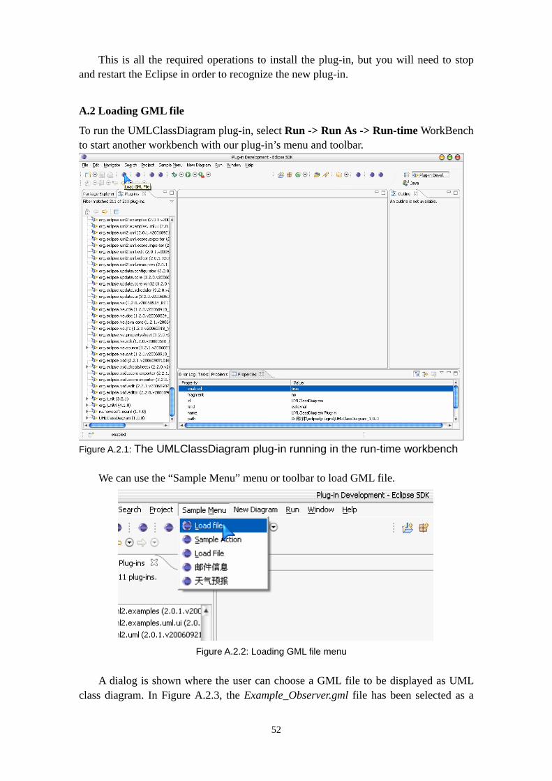
This is all the required operations to install the plug-in, but you will need to stop and restart the Eclipse in order to recognize the new plug-in.
A.2 Loading GML file
To run the UMLClassDiagram plug-in, select Run -> Run As -> Run-time WorkBench to start another workbench with our plug-in’s menu and toolbar.
Figure A.2.1: The UMLClassDiagram plug-in running in the run-time workbench
We can use the “Sample Menu” menu or toolbar to load GML file.
Figure A.2.2: Loading GML file menu
A dialog is shown where the user can choose a GML file to be displayed as UML
class diagram. In Figure A.2.3, the Example_Observer.gml file has been selected as a
52

sample.
Figure A.2.3: Loading GML file dialog
Once a GML file is loaded, it will be analysed to the corresponding UML class
diagram and displayed in the perspective.
Figure A.2.4: GML file loaded
All the class figures are displayed in the initial place. Then the user has to use the
53

drag and zoom actions to get the clear view on the UML class diagram.
Figure A.2.5: Good layout with drag and zoom actions
54

Matematiska och systemtekniska institutionen SE-351 95 Växjö
Tel. +46 (0)470 70 80 00, fax +46 (0)470 840 04
http://www.vxu.se/msi/