um primatech ccm ger 0263971 - wagner wsi
TRANSCRIPT

PrimaTech CCM
Hardware
Version 02 / 2008
Translation of the original Operating manual


3
PrimaTech CCM.
OPERATING MANUAL
VERSION 02/2008 ORDER NUMBER DOC0263972
Contents
1 ABOUT THESE INSTRUCTIONS 51.1 Languages 51.2 Warnings, notes and symbols in these instructions 5
2 GENERAL SAFETY INSTRUCTIONS 62.1 Safety instructions for the operator 62.1.1 Electrical plant and units 62.1.2 Personnel qualifi cations 62.1.3 A safe work environment 62.2 Safety instructions for staff 72.2.1 Safe handling of WAGNER powder spray units 72.2.2 Earth the unit 72.2.3 Paint hoses 72.2.4 Cleaning 82.2.5 Handling of powder lacquer 82.3 Correct use 82.4 Safety features 9
3 PRODUCT LIABILITY AND WARRANTY 103.1 Notes on product liability 103.2 Warranty 103.3 CE-conformity 11
4 DESCRIPTION 124.1 Fields of application, using in accordance with the instructions 124.1.1 Versions (Examples) 124.2 Scope of delivery 134.3 Specifi cations 134.3.1 Total system 134.3.2 CCM Prima 14
5 CONSTRUCTION AND INSTALLATION 155.1 Confi guring the PrimaTech CCM System 155.2 Overview of the PrimaTech CCM components 165.3 Assembling the components 195.4 Electrical connections 205.4.1 CCM Prima Connection side 205.4.2 Electrical connections and connection cables (overview) 215.4.3 Pneumatic connections and hoses 235.5 Grounding 245.6 Interlocking 255.6.1 PrimaTech CCM system without external interlocking 255.6.2 PrimaTech CCM system with external interlocking 26
6 START UP 286.1 Preparing for commissioning 286.1.1 Control panel from the CCM Prima central control unit 286.2 Start up the system 30

4
PrimaTech CCM.
OPERATING MANUAL
VERSION 02/2008 ORDER NUMBER DOC0263972
Contents
7. OPERATION 317.1 Setting the Electrostatic and the Powder Quantity 317.2 Recipes 317.2.1 Setting at the CCM Prima 317.2.2 Setting at the EPG Prima 317.3 Modifying and saving Corona recipes 327.4 Setting the powder quantity 327.5 Switch coating off 337.6 Color change and cleaning the system (with cleaning recipe) 347.6.1 Generating the cleaning recipe at the EPG Prima 347.6.2 Cleaning the powder feed to the gun 357.7 Disposal 37
8 RECTIFICATION OF MALFUNCTIONS 388.1 Error displays at the CCM Prima 388.2 Fault displays at the EPG Prima 39
8 SPARE PARTS 408.1 How to order spare parts 408.2 CCM Prima Control unit 41

5
PrimaTech CCM.
OPERATING MANUAL
VERSION 02/2008 ORDER NUMBER DOC0263972
The operating manual is available in the following languages:Language: Order No. Language: Order No.German EnglishFrench DutchItalian Spanish
1.2 WARNINGS, NOTES AND SYMBOLS IN THESE INSTRUCTIONS
1 ABOUT THESE INSTRUCTIONS
1.1 LANGUAGES
0263971 0263972 0263973 --- 0263974 0263975
Warning instructions in this manual point out particular dangers to users and equipmentand state measures for avoiding the hazard.These warning instructions fall into the following categories:
Danger - imminent danger. Non-observance will resultin death, serious injury and serious material damage.
Warning - possible danger. Non-observance can resultin death, serious injury and serious material damage.
Caution - a possibly hazardous situation.Non-observance can result in minor injury.
Note - provide information on particular characteristics and how to proceed.
Caution - a possibly hazardous situation.Non-observance can cause material damage.
SIHI_0100_GB
DANGERThis line warns of the hazard!Possible consequences of failing to observe the warning instructions.The signal word points out the hazard level.
The measures for preventing the hazard and its consequences.
SIHI_0103_GB
WARNINGThis line warns of the hazard!Possible consequences of failing to observe the warning instructions.The signal word points out the hazard level.
The measures for preventing the hazard and its consequences.
SIHI_0101_GB
CAUTIONThis line warns of the hazard!Possible consequences of failing to observe the warning instructions.The signal word points out the hazard level.
The measures for preventing the hazard and its consequences.
SIHI_0102_GB CAUTIONThis line warns of the hazard!Possible consequences of failing to observe the warning instructions. The signal wordpoints out the hazard level.
The measures for preventing the hazard and its consequences.
This operating manual contains information on the operation, repair and maintenance ofthe unit.
Always observe these instructions when operating the unit. This equipment can be dangerous if it is not operated in accordance with this manual. Compliance with these instructions constitutes an integral component of the warranty agreement.

6
PrimaTech CCM.
OPERATING MANUAL
VERSION 02/2008 ORDER NUMBER DOC0263972
2 GENERAL SAFETY INSTRUCTIONS
2.1 SAFETY INSTRUCTIONS FOR THE OPERATOR
2.1.1 ELECTRICAL PLANT AND UNITS
2.1.2 PERSONNEL QUALIFICATIONS
2.1.3 A SAFE WORK ENVIRONMENT
Keep these operating instructions to hand near the unit at all times.Always follow local regulations concerning occupational safety and accident prevention.
To be provided in accordance with the local safety requirements with regard to theoperating mode and ambient influences.May only be maintained by skilled electricians.Must be operated in accordance with the safety regulations and electrotechnicalregulations.Must be repaired immediately in the event of problems.Must be put out of operation if they pose a hazard.Must be de-energized before work is commenced on active parts.Secure the control unit against being switched back on without authorisation. Informstaff about planned work.Observe electrical safety regulations.
Ensure that the floor of the working area is anti-static (measurement in accordancewith EN 1081).Ensure that all persons within the working area wear anti-static shoes.Ensure that gloves that are being worn, are made of conductive material.The powder release must be electronically interlocked with the powder spray systemexhaust equipment.Excess coating material (overspray) must be collected up safely.Ensure that there are no ignition sources such as naked flame, glowing wires or hotsurfaces in the vicinity. Do not smoke.Maintain sufficient quantities of suitable fire extinguishers and ensure that they areserviceable.The operating company must ensure that an average concentration of powder paintin the air does not exceed 50% of the lower explosion limit (LEL = max. permittedconcentration of powder to air). If no reliable LEL value is available, the averageconcentration may not exceed 10g/m³.
7
PrimaTech CCM.
OPERATING MANUAL
VERSION 02/2008 ORDER NUMBER DOC0263972
2.2.1 SAFE HANDLING OF WAGNER POWDER SPRAY UNITS
2.2.2 EARTH THE UNIT
2.2.3 PAINT HOSES
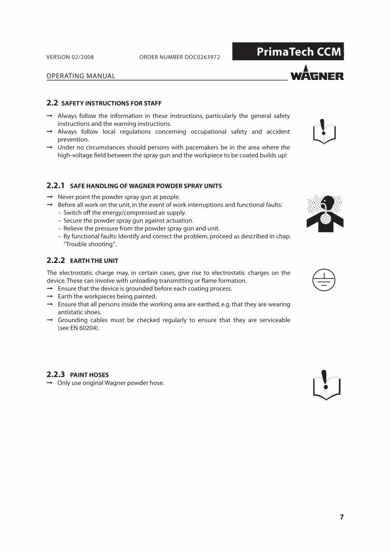
2.2 SAFETY INSTRUCTIONS FOR STAFF
➞ Only use original Wagner powder hose.
Always follow the information in these instructions, particularly the general safetyinstructions and the warning instructions.Always follow local regulations concerning occupational safety and accidentprevention.Under no circumstances should persons with pacemakers be in the area where thehigh-voltage field between the spray gun and the workpiece to be coated builds up!
Never point the powder spray gun at people.Before all work on the unit, in the event of work interruptions and functional faults:– Switch off the energy/compressed air supply.– Secure the powder spray gun against actuation.– Relieve the pressure from the powder spray gun and unit.– By functional faults: Identify and correct the problem, proceed as described in chap.
“Trouble shooting“.
The electrostatic charge may, in certain cases, give rise to electrostatic charges on thedevice.These can involve with unloading transmitting or flame formation.
Ensure that the device is grounded before each coating process.Earth the workpieces being painted.Ensure that all persons inside the working area are earthed, e.g. that they are wearingantistatic shoes.Grounding cables must be checked regularly to ensure that they are serviceable(see EN 60204).

8
PrimaTech CCM.
OPERATING MANUAL
VERSION 02/2008 ORDER NUMBER DOC0263972
2.2.4 CLEANING
2.3 CORRECT USE
2.2.5 HANDLING OF POWDER LACQUER
De-energize the unit electrically.Disconnect the pneumatic supply line.Relieve the pressure from the unit.Secure the control unit against being switched back on without authorisation.Only mobile industrial vacuum cleaners of design 1 (see EN 60335-2) may be used forgetting rid of dust build-ups.
Take note of the processing regulations laid down by the manufacturer of the powderpaint being used, when preparing or processing the powder.Take note of the manufacturer’s advice and the relevant environmental protectionregulations when disposing of powder paints.Implement the prescribed safety measures, in particular the wearing of safety glassesand safety clothing as well as the use of protective hand cream.Use dust masks or breathing apparatus.To ensure sufficient protection of health and the environment, only operate the devicein a powder booth or at a spray wall with activated ventilation (exhaust air).

9
PrimaTech CCM.
OPERATING MANUAL
VERSION 02/2008 ORDER NUMBER DOC0263972
2.4 SAFETY FEATURES
Plates bearing information for the user have been attached to the work openings of the powder coating booth.The plate size corresponds to the standard category Ø 100 mm.The label plates, which must be attached, are shown below.
High voltage!In the control cabinet:(25 mm; 0.98 inches)voltage before main switch
Forbidden for unauthorized persons!
Explosive atmosphere!
Forbidden for persons with a cardiac pacemaker!
Follow the instructions in the operating manual!
Fire, open light andsmoking prohibited!
Wear electrostaticallyconductive footwear!
Danger of crushing!
Risk of tripping!
Do not jump on the booth fl oor!
Danger of slipping!

10
PrimaTech CCM.
OPERATING MANUAL
VERSION 02/2008 ORDER NUMBER DOC0263972
3 PRODUCT LIABILITY AND WARRANTY
3.1 NOTES ON PRODUCT LIABILITY
3.2 WARRANTY
As a result of an EC regulation, effective as from January 1, 1990, the manufacturer shallonly be liable for his product if all parts come from him or are approved by him, and if thedevices are properly fitted , operated and maintained.If other makes of accessory and spare parts are used, the manufacturer‘s liability could befully or partially null and void.The usage of original WAGNER accessories and spare parts guarantees that all safetyregulations are observed.
This equipment is covered by the following manufacturing warranty.We will at our discretion repair or replace free of charge all parts which within 24 monthsin single-shift, 12 months in 2-shift or 6 months in 3-shift operation from date of receipt bythe Purchaser are found to be wholly or substantially unusable due to causes prior to thesale, in particular faulty design, defective materials or poor workmanship.The terms of the warranty are met at our discretion by the repair or replacement of theunit or parts thereof. The resulting costs, in particular shipping charges, road tolls, labourand material costs will be borne by us except where these costs are increased due to thesubsequent shipment of the unit to a location other than the address of the purchaser.This warranty does not cover damage caused by:Unsuitable or improper use, faulty installation or commissioning by the purchaser or athird party, normal wear, negligent handling, defective maintenance, unsuitable coatingproducts, substitute materials and the action of chemical, electrochemical or electricalagents, except when the damage is attributable to us.This warranty does not cover damage caused by:Unsuitable or improper use, faulty installation or commissioning by the purchaser or athird party, normal wear, negligent handling, defective maintenance, unsuitable coatingproducts, substitute materials and the action of chemical, electrochemical or electricalagents, except when the damage is attributable to us.Components not manufactured by Wagner are subject to the warranty terms of theoriginal maker.The replacement of a part does not extend the warranty period of the unit.The unit should be inspected immediately upon receipt.To avoid loss warranty, aniy apparent defect should be notified to us or the dealer inwriting within 14 days from date of sale of the unit.The right to commission warranty services to a third party is reserved.Warranty claims are subject to proof of purchase by submitting an invoice or deliverynote. If an inspection finds damage not covered by the present warranty, the repair will becarried out at the expense of the purchaser.Note that this warranty does not in any way restrict legally entitled claims or thosecontractually agreed to in our general terms and conditions.
J.Wagner AG

11
PrimaTech CCM.
OPERATING MANUAL
VERSION 02/2008 ORDER NUMBER DOC0263972
3.3 CE-CONFORMITY
PrimaTech CCM 0263850
Herewith we declare that the supplied version of
- CCM Prima, Order No. 0263070 complies with the following provisons apllying to it:
- 2004/108/EC (Electro-magnetic compatibility (EMC) guideline) - 94/9/EC (Atex-directive) - 2002/95/EC (RoHs-directive) - 2002/96/EC (WEEE-directive)
Applied standards, in particular:
- DIN EN 50177 - DIN EN 61241-0 - DIN EN 61241-1 - DIN EN 61000-6-1 - DIN EN 61000-6-2 - DIN EN 61000-6-3 - DIN EN 61000-6-4 - DIN EN 60529 - BGI 764
Identifi cation:
CE Certificate of ConformityThe certificate is enclosed with this product.The certificate of conformity can be reorderedfrom your WAGNER representative, quoting the product and serial number.
Part number:

12
PrimaTech CCM.
GCM Prima
SETUP
12345678
-Pos.
MODE
SELECT SET
inchcm
+
22
CCM Prima
!O / I
O II
O
OII
RESET
I
O
1 2INT.
EXT.
2x2x
EPG Prima
Tribo Corona100
908070605040302010kV
5
4
3
2
1
μA
120100806040302015105μA
2x
EPG Prima
Tribo Corona100
908070605040302010kV
5
4
3
2
1
μA
120100806040302015105μA
2x
EPG Prima
Tribo Corona100
908070605040302010kV
5
4
3
2
1
μA
120100806040302015105μA
2x
EPG Prima
Tribo Corona100
908070605040302010kV
5
4
3
2
1
μA
120100806040302015105μA
2x
EPG Prima
Tribo Corona100
908070605040302010kV
5
4
3
2
1
μA
120100806040302015105μA
2x
EPG Prima
Tribo Corona100
908070605040302010kV
5
4
3
2
1
μA
120100806040302015105μA
2x
EPG Prima
Tribo Corona100
908070605040302010kV
5
4
3
2
1
μA
120100806040302015105μA
2x
EPG Prima
Tribo Corona100
908070605040302010kV
5
4
3
2
1
μA
120100806040302015105μA
2x
RCM Prima
RESET
1
100908070605040302010
%
100908070605040302010
%
2
RESET
m/s m/s
MM
GCM Prima
SETUP
12345678
-Pos.
MODE
SELECT SET
inchcm
+
22
SCM Prima
EPG Prima
Tribo Corona100908070605040302010kV
5
4
3
2
1
μA
120100806040302015105μA
2x
EPG Prima
Tribo Corona100908070605040302010kV
5
4
3
2
1
μA
120100806040302015105μA
2x
EPG Prima
Tribo Corona100908070605040302010kV
5
4
3
2
1
μA
120100806040302015105μA
2x
EPG Prima
Tribo Corona100908070605040302010kV
5
4
3
2
1
μA
120100806040302015105μA
2x
EPG Prima
Tribo Corona100908070605040302010kV
5
4
3
2
1
μA
120100806040302015105μA
2x
EPG Prima
Tribo Corona100908070605040302010kV
5
4
3
2
1
μA
120100806040302015105μA
2x
EPG Prima
Tribo Corona100908070605040302010kV
5
4
3
2
1
μA
120100806040302015105μA
2x
EPG Prima
Tribo Corona100908070605040302010kV
5
4
3
2
1
μA
120100806040302015105μA
2x
OPERATING MANUAL
VERSION 02/2008 ORDER NUMBER DOC0263972
4 DESCRIPTION
4.1 FIELDS OF APPLICATION, USING IN ACCORDANCE WITH THE INSTRUCTIONS
The PrimaTech CCM Control Unit is used in automatic coating systems. The Control unit controls according to the model:
● Powder output quantity ● Powder atomization ● High voltage ● Current limit ● Reciprocator settings ● Gap controller
4.1.1 VERSIONS (EXAMPLES)
Basic model PrimaTech CCM with:CCM Prima Central controllerGCM Prima Gap controllerRCM Prima Reciprocator controllerEPG Prima Gun controller
Extension modul with:SCM Extension moduleGCM Prima Gap controllerEPG Prima Gun controller

13
PrimaTech CCM.
OPERATING MANUAL
VERSION 02/2008 ORDER NUMBER DOC0263972
Quantity Part-No. Description
1 0263070 PrimaTech CCM
The standard equipment includes:
1 0263850 CE-Declaration of Conformity
1 0263971 Operating manual German
1 see Chapter 1.1 Operating manual in the local language
4.2 SCOPE OF DELIVERY
Dimensions:
High 1700 mm; 66.93 inches
Width 630 mm; 24.80 inches
Depth 660 mm; 25.98 inches
Weight approx. 78 kg; 172 lb
Electrical:
a) Used without ICC …
Mains power input voltage 85 VAC-250 VAC / 47-440 Hz
Input power 40 watt
b) Used with ICC …
Mains power input voltage 230 V± 10 % / 50-60 Hz
Protection class IP 54
Temperature range 5-45°C; 41-113°F
Danger zone EX II 3 D (Zone 22 in the rack with cover)
Pneumatics:
Compressed air input pressure 0.6-0.8 MPa; 6-8 bar; 87-116 psi
Compressed air quality according to ISO 8573.1
3.5.2
4.3 SPECIFICATIONS
4.3.1 TOTAL SYSTEM
SIHI_05034_ENG
WARNINGOutgoing air containing oil!Risk of poisoning if inhaled.
Provide water-free and oil-free compressed air (quality standard3.5.2 as per ISO 8573.1) 3.5.2 = 5 μm / +7°C; 44.6°F / 0.1 mg/m³.

14
PrimaTech CCM.
OPERATING MANUAL
VERSION 02/2008 ORDER NUMBER DOC0263972
4.3.2 CCM PRIMA
Dimensions:
High 136 mm; 5.35 inches
Width 270 mm; 10.63 inches
Depth 340 mm; 13.39 inches
Weight approx. 8 kg; 17.6 lb
Electrical:
Mains power input voltage 85 VAC-250 VAC / 47-440 Hz
Input power 40 watt
Protection class IP 54
Temperature range 5-45°C; 41-113°F

15
PrimaTech CCM.
OPERATING MANUAL
VERSION 02/2008 ORDER NUMBER DOC0263972
5 CONSTRUCTION AND INSTALLATION
5.1 CONFIGURING THE PRIMATECH CCM SYSTEM
Based on the following table, you can confi gure the necessary components, dependent on the number of guns.
Item Components Quantity
Corona Spray gun 2 4 6 8 10 12 14 16
A Rack 1 1 1 1 1 2 2 2
B Metal sheet 9 7 5 3 - 10 8 6
C CCM Prima Control unit 1 1 1 1 1 1 1 1
D SCM Prima Control unit 0 0 0 0 1 1 1 1
E EPG Prima Control unit 2 4 6 8 10 12 14 16
1 Connection set 2 4 6 8 10 12 14 16
8 Mains cable 1 1 1 1 1 1 1 1
G Loop cable 0 0 0 0 1 1 1 1

16
PrimaTech CCM.
P_00103
P_00105
P_00168
P_00176CCM Prima
!O / I
O I
I
O
OII
RESET
I
O
1 2
INT.
EXT.
2x2x
OPERATING MANUAL
VERSION 02/2008 ORDER NUMBER DOC0263972
5.2 OVERVIEW OF THE PRIMATECH CCM COMPONENTS
Rack: Order No. 0360090
The Rack contains:Distributor block, complete Order No. 0263325 consisting of:Straight, pluggable fi tting Order No. 9992743Stopper Order No. 9998201Grounding cable, complete Order No. 0264332
Basic frame with six storage positions for:● one CCM Prima and a maximum of 11 control units
● a maximum of 12 control units (without CCM Prima)
Metal sheet: Order No. 0360238
To close off free places if the holder is not fully loaded.
The metal sheet contains:Star washer Order No. 9922101Fillister head screw Order No. 9903328Hex nut Order No. 9910108
Cable clamp: Order No. 0360239
For securing the pneumatic hoses and electric cables.
CCM Prima Order No. 00263070
Central control and operating unit for all PrimaTech modules.Connections for:● 8 EPG Prima● 1 GCM Prima Gap controller● Interlocking for conveying equipment and booths● 1 equipment plug „extension“ or 1 SCM Prima for a further 8 guns
A maximum of 8 spray guns can be operated without anSCM Prima extension module.

17
PrimaTech CCM.
SCM Prima
P_00517
P_00518
EPG Prima
Tribo Corona100908070605040302010kV
5
4
3
2
1
μA
120100806040302015105μA
2x
P_00519
RCM Prima
RESET
1
100908070605040302010
%
100908070605040302010
%
2
RESET
m/s m/s
MM
P_00520
GCM Prima
SETUP
12345678
-Pos.
MODE
SELECT SET
inchcm
+
22
P_00515
OPERATING MANUAL
VERSION 02/2008 ORDER NUMBER DOC0263972
SCM Prima Order No. 0263071
Extension module for 8 EPG Prima Universal control units. Using this, a further 8 guns can be operated in addition to the fi rst8 guns with the basic version.
● 8 EPG Prima● 1 GCM Prima Gap controller● 1 equipment plug “extension“ or 1 SCM Prima for a further 8 guns
EPG Prima Order No. 0360010
Universal control unit for Corona or Tribo powder spray guns
One EPG Prima is needed for each gun.
GCM Prima Order No. 0263114
Control unit to interrupt the coating process in the gaps between the individual workpieces.
A GCM Prima can control a maximum of eight guns (EPG Prima).
RCM Prima Order No. 0263115
Control unit for one or two EBA 1 or EBA 6 reciprocators.
A frequency converter box ICC ... is needed in addition for the electric power supply.
GHCM 2007
GHCM-S210-TD200 Order No. 3151269Gap controller for up to 16 horizontally aligned guns.
GHCM-S121-TD200 Order No. 3151341Height controller for up to 16 vertically aligned guns.

18
PrimaTech CCM.
P_00516
P_00106
OPERATING MANUAL
VERSION 02/2008 ORDER NUMBER DOC0263972
ICC 2075 Order No. 0263121Frequency converter (0.75 kW) for 2 EBA 1 reciprocators.
ICC 1075 Order No. 0263122Frequency converter (0.75 kW) for 1 EBA 1 reciprocator.
ICC2150 Order No. 0263123Frequency converter (1.5 kW) for 2 EBA 6 reciprocators.
ICC 1150 Order No. 0263124Frequency converter (1.5 kW) for 1 EBA 6 reciprocator.
Loop cable
Length 0.55 m; 1.81 ft Order No. 02412691.4 m; 4.59 ft Order No. 026324910 m; 32.81 ft Order No. 0263233

19
PrimaTech CCM.
P_00177
2
3
4
1
5
OPERATING MANUAL
VERSION 02/2008 ORDER NUMBER DOC0263972
5.3 ASSEMBLING THE COMPONENTS
Procedure:
1. Install rack (1) at the location.2. Lift cover plate 2 on the rear of the rack 1
upwards and out and unhinge it.3. Install CCM Prima (3) in the top compartment
of rack 1 (Recommendation).4. Install EPG Prima control units (4) from top
to bottom.5. Close of any empty rack compartments
with metal sheets (5).5. Hang cover plate 2 back in position on the
back of the rack 1.

20
PrimaTech CCM.
87
65
43
21
1
2
3 4
5
678
9
P_00178
OPERATING MANUAL
VERSION 02/2008 ORDER NUMBER DOC0263972
5.4 ELECTRICAL CONNECTIONS
5.4.1 CCM PRIMA CONNECTION SIDE
1 “Input power supply“ equipment plug2 “Output power supply“ equipment socket3 EPG Prima equipment sockets4 “Extension“ equipment plug5 “External interlock“ equipment socket6 “Gap controller“ equipment socket7 Secondary fuse8 Primary fuse9 “Operating ground“ grounding connection

21
PrimaTech CCM.
9
8
11
7
1
12
P_00179
CCM Prima
RCM Prima
1
3
2
4
5 6
7 8
EPG
I
O
I
O
OPERATING MANUAL
VERSION 02/2008 ORDER NUMBER DOC0263972
5.4.2 ELECTRICAL CONNECTIONS AND CONNECTION CABLES (OVERVIEW)
GCM Prima Connection box
The fi gure above is just to provide an overview. There is almost no limit to the number of possible confi gurations, because of the modular construction of the PrimaTech CCM system.
EPG Prima No. 1 EPG Prima No. 2 GCM Prima No. 1

22
PrimaTech CCM.
P_00107 P_00106
P_00256
P_00257
P_00258
P_00263 P_00264
P_00388
P_00259P_00262
OPERATING MANUAL
VERSION 02/2008 ORDER NUMBER DOC0263972
CCM / EPG (1) ConnectorCCM Prima-EPG Prima connection set Order No. 0263092consisting of:1.2 m; 3.94 ft connection cable Order No. 02632140.55; 1.81 ft m mains cable Order No. 0241269
CCM / GCM (2) Connector1.4 m; 4.59 ft CCM Prima-GCM Primaconnection cable Order No. 0263241
GCM / GCM (3) Connector1.2 m; 3.94 ft GCM Prima-GCM Primaconnection cables Order No. 0263253
Extension (4) to light barrier, light curtain, conveyor clock generator, connection box and to 10 m; 32.81 ft GCM Prima-GCM Primaconnecting cable Order No. 0263252
1.53 yd / 1.4 m (7) Extension set Order No. 0263094consisting of:1.4 m; 4.59 ft cable extension Order No. 02632481.4 m; 4.59 ft mains extension Order No. 0263249
10.94 yd / 10 m (7) Extension set Order No. 0263093consisting of:10 m; 32.81 ft cable extension Order No. 026323210 m; 32.81 ft mains extension Order No. 0263233
Mains cable (8)Europe Order No. 0241270Switzerland Order No. 0241271USA Order No. 0264626Japan Order No. 0264625Grounding cable for Japan Order No. 0236219
Short circuit insert (9)Short circuit insert Order No. 0263217(contained in the CCM Prima)must be used on the CCM Prima equipment socket if no gap controller is connected

23
PrimaTech CCM.
12
3
4
EPG Prima
P_00500
OPERATING MANUAL
VERSION 02/2008 ORDER NUMBER DOC0263972
5.4.3 PNEUMATIC CONNECTIONS AND HOSES
Hose 4/6, black (1)Order No. 9982079
Connection hose between control units and spray guns. Available by the yard/meter.
Hose 6/8, blue (2)Order No. 9982062
Dosing air hose from the EPG Prima to the powder injector.
Hose 6/8, red (3)Order No. 9982063
Feed air hose from the EPG Prima to the powder injector.
Hose 6/8, green (4)Order No. 9982077
Fluid air hose from the air diffuser to the EPG Prima.
Compressed air connection with 1/2“ internal threadAir pressure 0.6-0.8 MPa;6-8 bar; 87-116 psi
Air diffuser on the rack(included in rack)
24
PrimaTech CCM.
OPERATING MANUAL
VERSION 02/2008 ORDER NUMBER DOC0263972
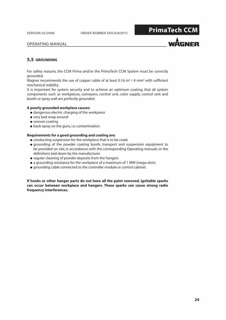
5.5 GROUNDING
For safety reasons, the CCM Prima and/or the PrimaTech CCM System must be correctly grounded. Wagner recommends the use of copper cable of at least 0.16 in² / 4 mm² with suffi cient mechanical stability.It is important for system security and to achieve an optimum coating, that all systemcomponents such as workpieces, conveyors, control unit, color supply, control unit and booth or spray wall are perfectly grounded.
A poorly grounded workpiece causes: ● dangerous electric charging of the workpiece ● very bad wrap around ● uneven coating ● back-spray on the guns, i.e. contamination.
Requirements for a good grounding and coating are: ● conducting suspension for the workpiece that is to be coate ● grounding of the powder coating booth, transport and suspension equipment to
be provided on site, in accordance with the corresponding Operating manuals or the defi nitions laid down by the manufacturer.
● regular cleaning of powder deposits from the hangers ● a grounding resistance for the workpiece of a maximum of 1 MW (mega ohm) ● grounding cable connected to the controller module or control cabinet.
If hooks or other hanger parts do not have all the paint removed, ignitable sparks can occur between workpiece and hangers. These sparks can cause strong radiofrequency interferences.

25
PrimaTech CCM.
1
2
3
4
5
6
7
8
9
10
11
12
13
14
15
16
P_00501
P_00502
P_00503
OPERATING MANUAL
VERSION 02/2008 ORDER NUMBER DOC0263972
5.6 INTERLOCKING
5.6.1 PRIMATECH CCM SYSTEM WITHOUT EXTERNAL INTERLOCKING
The CCM Prima control unit is delivered with the “Interlocking“ plug installed.
All interlocks are bridged, as shown below.
View from inside
“Interlocking“plug
View from below
Shorting bridgeExternal emergency stop
Shorting bridgeInterlockingexhaust air
CAUTIONExhaust air interlock!
➞ The exhaust air interlock must be achieved using the shorting bridges 3 and 4.➞ If that is not possible, the mains socket on the CCM Prima must be electrically
interlocked with the exhaust air equipment.

26
PrimaTech CCM.
3
2
4
1 9
10
12
11
13
6
5
7
8
15
14
16
(1)
(2)
P_00504
OPERATING MANUAL
VERSION 02/2008 ORDER NUMBER DOC0263972
5.6.2 PRIMATECH CCM SYSTEM WITH EXTERNAL INTERLOCKING
Plug pin assignment:
External trigger for CCM Prima emergency stop
etc
“Interlocking“plug
System error message
Emergency stop*trigger for external
devices
Potential-free relaysChange-over contact see diagram:Relay change-over contactsin the CCM Prima
potential-freecontact
Conveyor interlock
potential-free connection
Release relay
Exhaust air interlock
potential-free connection
Release relay
* The switch is closed between pin 12 and pin 13 during normal operation. The switch is opened if the emergency stop button is operated.
CAUTIONEquipment damage!
➞ “Interlocking“ connector plug: Pins 1 to 11 only feed 24 VDC control voltage and are supplied from the CCM Prima. Applying an external voltage to these pins destroys the CCM Prima.
➞ Pins 12 and 13 are used to trigger the external emergency stop function. Maximum permitted contact load is 220 V / 1 A.
Release 24 VDC/100 mA max.
+24 VDC/100 mA max.
GND

27
PrimaTech CCM.
16
15
14
P_00505
OPERATING MANUAL
VERSION 02/2008 ORDER NUMBER DOC0263972
Diagram: Relay - change-over contact in the CCM Prima:
As shown:No error message, system OK
Maximum contact load:- Switching power max. 20 W / 40 VA- Switching voltage max. 48 VDC- Switching current max. 1 A

28
PrimaTech CCM.
CCM Prima
!O / I
O I
I
O
OII
RESET
I
O
1 2
INT.
EXT.
2x2x
P_00
506
8 5 4 325 1615 1427 719 20
6 2 110 11 924 12 1322 18 17
28 26
23 21
30 29
OPERATING MANUAL
VERSION 02/2008 ORDER NUMBER DOC0263972
6 START UP
WARNINGIncorrect installation/operation!Risk of injury and damage to equipment
When putting into operation and for all work, read and followthe operating instructions and safety regulations for the additionallyrequired system components.
SIHI 0050 GB
6.1 PREPARING FOR COMMISSIONING
6.1.1 CONTROL PANEL FROM THE CCM PRIMA CENTRAL CONTROL UNIT

29
PrimaTech CCM.
OPERATING MANUAL
VERSION 02/2008 ORDER NUMBER DOC0263972
1 Main switch 16 “Fault“ indicator
2 “Mains supply“ indicator 17 “Start reciprocators“ button
3 “Emergency stop“ button 18 “Stop reciprocators“ button
4 “External Emergency stop“ indicator 19 “Reciprocator 1 in operation“ indicator
5 “Internal Emergency stop“ indicator 20 “Reciprocator 2 in operation“ indicator
6 “System ON“ key switch 21 “Manual setting recipe“ button
7 “System OFF“ button 22 “Manual setting recipe“ indicator
8 “System in operation“ indicator 23 “Profi le parts recipe“ button
9 High voltage/powder “OFF“ 24 “Profi le parts recipe“ indicator
10 “Start manual“ button 25 “Post-coating recipe“ button
11 “Ready manual“ indicator 26 “Post-coating recipe“ indicator
12 “Start automatic“ button 27 “Surface parts recipe“ button
13 “Ready automatic“ indicator 28 “Surface parts recipe“ indicator
14 High voltage/powder “ON“ indicator 29 “Conveyor running“ indicator
15 “Fault reset“ button 30 “Booth exhaust air“ indicator

30
PrimaTech CCM.
CCM Prima
!O / I
O I
I
O
OII
RESET
I
O
1 2
INT.
EXT.
2x2x
P_00
506
830 29 14
6 2 110 11 912 13
OPERATING MANUAL
VERSION 02/2008 ORDER NUMBER DOC0263972
6.2 START UP THE SYSTEM
Procedure:
1. Switch on the power supply with main switch (1) on the CCM Prima control unit:Display (2) lights up.
2. Switch on the system by turning key switch (6) in a clockwise direction:Display (8) “System in operation“ lights up. The key can be removed.
3. Ensure fl uidization of the powder container.
The further procedure is dependent on the selected operating mode (manual or automa-tic).
How to proceed with “Manual“ operating mode:4. Switch on the boot exhaust air and wait until full suction capacity has been reached
and the “Booth exhaust air“ indicator 30 lights up.5. Press button 10 “Manual start“. The indicators 11 “Manual ready“ and 14 “High voltage/
Powder ON“ light up.6. Please refer to Chapter 7.1 “Setting the powder quantity“ for the further procedure.
How to proceed with “Automatic“ operating mode:5. Switch on the boot exhaust air and wait until full suction capacity has been reached
and the “Booth exhaust air“ indicator 30 lights up.6. Press button 12 “Automatic start“.
“Ready automatic“indicator(13) lights up.7. The guns can now be switched on and off with the conveyor interlock.
The displays 14 “High voltage/Powder ON“ and 29 “Conveyor running“ light up.

31
PrimaTech CCM.
EPG Prima
2x
Tribo Corona100908070605040302010kV
5
4
3
2
1
μA
120100806040302015105μA
2x
P_00507
P_00508
2x2x
1
2
3
4
OPERATING MANUAL
VERSION 02/2008 ORDER NUMBER DOC0263972
7. OPERATION
7.1 SETTING THE ELECTROSTATIC AND THE POWDER QUANTITY
The electrostatic and the powder quantity are set at the individual EPG Prima control units.
Setting the powder quantitySetting the electrostatic
7.2 RECIPES
7.2.1 SETTING AT THE CCM PRIMA
● Surface parts (1)
● Post-coating (2)
● Profile parts (3)
● Manual setting (4)
The recipes from all the connected EPG Prima units can be adjusted together from the CCM Prima.
P_00508
2x2x
1
2
3
4
The EPG Prima control unit has 4 pre-defi ned recipes for the Corona gun. The factorysettings for these recipes are as follows.
● Surface parts (1) 80 kV 120 µA
● Post-coating (2) 50 kV 80 µA
● Profile parts (3) 60 kV 60 µA
● Manual setting (4) 80 kV 100 µA
7.2.2 SETTING AT THE EPG PRIMA

32
PrimaTech CCM.
P_00510
2x
Tribo Corona100908070605040302010kV
5
4
3
2
1
μA
120100806040302015105μA
2x
P_00509
6
7
4 3 5
2
1
OPERATING MANUAL
VERSION 02/2008 ORDER NUMBER DOC0263972
7.3 MODIFYING AND SAVING CORONA RECIPES
Procedure:
1. Increase or decrease the high voltage with button 1 or 2.
2. Increase or decrease the current limiting with button 3 or 4.
3. The unit has switched to manual setting recipe 5.4. Press and hold the recipe button until the middle 6
diodes light up on both LED displays 6 and 7.5. The new values are now added to this recipe and
are retained, even if the control unit is switched off.
7.4 SETTING THE POWDER QUANTITY
1
32
Procedure:
1. Setting is done in automatic mode.The guns are in the booth and the exhaust air must be switched on.
2. Adjust the overall air quantity with the rotaryregulator 2. The overall air quantity infl uences the powder feed speed.The optimum powder feed speed is dependent on the system confi guration, the type of powder and above all, in the cross section of the powder feed hose.If the feed speed is too slow, the charged powder starts to pulse.If the speed is too high, the powder doesn’t stay adhered to the object to be coated any more.With standard powder types, we recommend that the overall air quantity is set between 2 and 6 m³/h.You will fi nd more information in the powder injec-tor Operating manual.
3. The powder quantity can be adjusted using therotary controller 1 between 0 and 100%.
4. The gun air can be adjusted using the rotarycontroller 3.Please refer to the spray gun Operating manual.
S Adjusting range for a column nozzleP Adjusting range for a defl ector coneT Adjusting range for the Tribo air

33
PrimaTech CCM.
CCM Prima
!O / I
O I
I
O
OII
RESET
I
O
1 2
INT.
EXT.
2x2x
P_00
506
30 7
110 9
OPERATING MANUAL
VERSION 02/2008 ORDER NUMBER DOC0263972
7.5 SWITCH COATING OFF
HINT:The spray guns and the powder-conveying parts must be blown through each time there is a break in work.
Procedure:
1. Switch off powder feed with button 9 “High voltage/Powder OFF“:The booth exhaust air remains switched on and display 30 stays on.
2. Switch off fl uidization.3. Pull the powder injectors out of the feed system so that no more powder can be
conveyed.4. Press button 10 “Manual start“: The spray guns are blown out empty.5. Switch the system off with button 7 “System OFF“.
The PrimaTech CCM System can now be switched off with main switch 1.

34
PrimaTech CCM.
EPG Prima
2x
Tribo Corona100908070605040302010kV
5
4
3
2
1
μA
120100806040302015105μA
2x
P_00512
OPERATING MANUAL
VERSION 02/2008 ORDER NUMBER DOC0263972
7.6 COLOR CHANGE AND CLEANING THE SYSTEM (WITH CLEANING RECIPE)
In the case of a color change, powder residues must be thoroughly removed from all the powder-conveying parts throughout the complete coating system.
When a thorough cleaning of the booth is carried out, an empty container should be made available for the powder that is reclaimed from the booth.
7.6.1 GENERATING THE CLEANING RECIPE AT THE EPG PRIMA
The cleaning recipe is intended to provide optimum cleaning of the powder injector as well as the gun’s high-voltage electrode, in combination with the cleaning (impulse-fl ushing) of the powder center.The cleaning recipe only has to be generated once at each EPG Prima and can then always be used again.The steps necessary for the generation of a cleaning recipe are described in the following.
Procedure:
1. Switch the EPG Prima control unit on with button A.2. Select any recipe at the EPG Prima (Recommendation: hand icon D).3. Set the electrostatic (kV, µA) to the lowest level with buttons B and C (10 kV, 5 µa).4. Save the settings on the selected recipe button. Press and hold the recipe button until
the middle 6 diodes light up on both bar graph LED displays 1 and 2. Saving recipes is described in detail on the EPG Prima Operating manual.
1
2
B C D A

35
PrimaTech CCM.
CCM Prima
!O / I
O I
I
O
OII
RESET
I
O
1 2
INT.
EXT.
2x2x
P_00
506
918 17
OPERATING MANUAL
VERSION 02/2008 ORDER NUMBER DOC0263972
7.6.2 CLEANING THE POWDER FEED TO THE GUN
Procedure:
1. Switch off the powder feed to the gun with button 9 “High voltage/Powder OFF“ at the CCM Prima.
2. Switch off the stroke movement with button 18 “Stop reciprocators“.3. Move the guns to the cleaning position.4. Move the suction system in the powder center up out of the powder container.5. Remove the powder container from the vibrator table.6. Clean external suction tube with compressed air.7. Set the air quantity controller at all EPG Prima as per the fi gure shown here. ● Set the total air at rotary knob 1 in the indicated range. Hose lengths up to 6 m: 6m³/h Hose lengths greater than 6 m: 10m³/h - maximum ● Set the powder quantity setting at rotary knob 2 in the scale value range 40 - 60
(indicated range) ● Set the atomizing air at rotary knob 3 in the indicated range.

36
PrimaTech CCM.
EPG Prima
2x
Tribo Corona100908070605040302010kV
5
4
3
2
1
μA
120100806040302015105μA
2x
P_00512
EPG Prima
2x
Tribo Corona100908070605040302010kV
5
4
3
2
1
μA
120100806040302015105μA
2x
P_00513
OPERATING MANUAL
VERSION 02/2008 ORDER NUMBER DOC0263972
1 2 3
8. Call the cleaning recipe at all EPG Prima (see Chapter 7.6.1).9. Switch on guns at CCM Prima..10. Activate the impulse fl ushing (if available) in the powder center.11. Once the cleaning process is complete (impulse fl ushing), switch guns off with
button 9 “High voltage/Powder OFF“.12. Switch stroke movement back on again with Button 17 “Start reciprocators“ and move
the guns back to the work position.13. Call the partial-coating recipe again and set the air quantity controller back to the
original value (see example below).

37
PrimaTech CCM.
OPERATING MANUAL
VERSION 02/2008 ORDER NUMBER DOC0263972
7.7 DISPOSAL
NoteDo not dispose of waste electrical equipment with the house-hold refuse!In accordance with European Directive 2002/96/EC on the disposalof waste electrical equipment and its implementation in nationallaw, this product may not be disposed of with the household refuse,but must rather be recycled in an environmentally correct manner.Your waste Wagner electrical device will be taken back by us or ourrepresentatives and disposed of environmentally correctly. Pleasecontact one of our service points or one of our representatives or usdirectly to this purpose.

38
PrimaTech CCM.
OPERATING MANUAL
VERSION 02/2008 ORDER NUMBER DOC0263972
8 RECTIFICATION OF MALFUNCTIONS
SIHI_05019_ENG
DANGERIncorrect maintenance/repair!Danger to life and equipment damage.
Maintenance, repairs or the exchange of units or parts there ofmust be carried out by trained personnel, outside the dangerareas.
8.1 ERROR DISPLAYS AT THE CCM PRIMA
Hint:A fault can also be triggered by one of the modules integrated in the controller (EPG Prima, RCM Prima, etc.).
Procedure: ● Check which unit has triggered the fault. ● Eliminate the fault at the corresponding unit by reference to the unit’s Operating
manual. ● Press the Reset button on the CCM Prima.
Malfunction Cause Rectifi cation
Operating display does not light up
● Mains supply is not switched on
● No power supply● Fuse 2/1 AT is defective
● Switch mains supply on. If necessary, release the emergency stop button● Check the power supply● Replace the fuse
Error display lights up ● One of more devices has a fault
● The mains power switch has been operated at an EPG, during normal operation
● Locate and eliminate the malfunction at the correspon- ding device (see the Operating manuals for the devices)● Press the Reset button
High voltage and powder switch do not switch even when released through the CCM
● Gap controller short circuit plug has not been set
● See Chapter: 5.4.1 “CCM Prima Connection side“, Item 6

39
PrimaTech CCM.
3
2
1
μA
40302015105μA
12345
P_00514
OPERATING MANUAL
VERSION 02/2008 ORDER NUMBER DOC0263972
Malfunction Cause Rectifi cation
System cannot be started with the key switch(LED 4 or 5 lights up)
● Internal or external emergency stop has been operated● Emergency stop bridges in the interlocking plug are not in place● Plug has not been inserted in the “External controller“ equipment socket
● Release emergency stop button
● See Chapter: 5.6.2 “PrimaTech CCM system with external interlocking“● See Chapter: 5.4.1 “CCM Prima Connection side“, Item 4
8.2 FAULT DISPLAYS AT THE EPG PRIMA
Error message overview:
If LED 1 lights up: Contact the Wagner Service Team
If LED 2 lights up: Contact the Wagner Service Team
If LED 3 lights up: Tribo current was lower than the set limit value for more that 10 seconds
If LED 4 lights up: Tribo current higher than 12 µA(ATEX: Switch the unit off )
If LED 5 lights up: Grounding monitoring fault

40
PrimaTech CCM.
OPERATING MANUAL
VERSION 02/2008 ORDER NUMBER DOC0263972
8 SPARE PARTS
8.1 HOW TO ORDER SPARE PARTS
WARNINGIncorrect maintenance/repair!Risk of injury and damage to equipment.
➞ Only a WAGNER service center or special trained personnel may carry out repairs and replace parts.
➞ Before all work on the unit and in the event of workinterruptions:
- Switch off the energy/compressed air supply. - Ensure that all system components are grounded.
- Secure the control unit against being switched back on without authorisation.
➞ Observe the operating and service instructions when carrying out all work.

41
PrimaTech CCM.
OPERATING MANUAL
VERSION 02/2008 ORDER NUMBER DOC0263972
8.2 CCM PRIMA CONTROL UNIT
Item K Quantity Order No. Description
0263070 CCM Prima Control unit
0264900 Spare parts set (fuses, contained in the CCM Prima)
9951116 2A Fuses
9951117 1A Fuses

42
PrimaTech CCM.
OPERATING MANUAL
VERSION 02/2008 ORDER NUMBER DOC0263972
GermanyJ.WAGNER GmbHOtto-Lilienthal-Str. 18Postfach 1120D- 88677 MarkdorfPhone: +49/ 7544/ 505-0Fax: +49/ 7544/ 505-200E-mail: [email protected]
SwitzerlandJ.WAGNER AGIndustriestrasse 22Postfach 663CH- 9450 AltstättenPhone: +41/ 71/ 757 2211Fax: +41/ 71/ 757 2222E-mail: [email protected]
BelgiumEstee IndustriesLeenbeekstraat 9B- 9770 KruishoutemPhone: +32/ 9/ 388 5410Fax: +32/ 9/ 388 5440E-mail: [email protected]
DenmarkWAGNER Industrial Solution ScandinaviaViborgvej 100, SkægkærDK-8600 SILKEBORGPhone: +45/ 70 200 245Fax: +45/ 86 856 027E-mail: [email protected]
Great BritainWAGNER Spraytech (UK) Ltd.The Couch House2, Main RoadGB- Middleton Cheney OX17 2NDPhone: +44/ 1295/ 714200Fax: +44/ 1295/ 710100E-mail: [email protected]
FranceWagner - Division Solutions IndustriellesParc Gutenberg - Bâtiment F8 voie la CardonF- 91127 PALAISEAU CedexPhone: +33/ 1/ 825/ 011111Fax: +33/ 1/ 69 19 46 55E-mail: [email protected]
NetherlandsWAGNER Systemen NederlandProostwetering 105 CNL- 3543 AC UtrechtPhone: +31/ 30/ 2410 688Fax: +31/ 30/ 2410 765E-mail: [email protected]
ItalyWAGNER Itep S.p.AVia Santa Veccia, 109I- 22049 Valmadrera - LCPhone: +39/ 0341/ 212211Fax: +39/ 0341/ 210200E-mail: [email protected]
JapanWAGNER HOSOKAWA Micron Ltd.No. 9, 1-ChomeShodai Tajka, Hirakata-ShiOsaka 673-1132Phone: +81/ 728/ 566 751Fax: +81/ 728/ 573 722E-mail: [email protected]
AustriaJ.WAGNER GmbHOtto-Lilienthal-Str. 18Postfach 1120D- 88677 MarkdorfPhone: +49/ 7544/ 505-0Fax: +49/ 7544/ 505-200E-mail: [email protected]
SwedenWAGNER Industrial Solutions ScandinaviaSkolgatan 61SE - 568 31 SKILLINGARYDPhone: +46/ 370/ 798 30Fax: +46/ 370/ 798 48E-mail: [email protected]
SpainWAGNER Spraytech Iberica S.A.P.O. Boc., 132, Ctra. N- 340, KM 1245,4E- 08750 Molins de Rei (Barcelona)Phone: +34/ 93/ 680 0028Fax: +34/ 93/ 680 0555E-mail: [email protected]
ChinaWAGNER Spraytech Shanghai Co Ltd.4 th Flr. No. 395 Jiangchanxi RoadShibei Industrial ZoneShanghai 200436Phone: +86/ 2166 5221 858Fax: +86/ 2166 5298 19E-mail: [email protected]
USAWAGNER Systems Inc.300 Airport Road, Unit 1Elgin, IL 60123
Phone: +1/ 630/ 503-2400Fax: +1/ 630/ 503-2377E-mail: [email protected]


CERTIFIE
D0263972