ultramid® (pa) – hauptbroschüre, deutschview/en/8798535461333.ultramid... · (ultramid ® b),...
TRANSCRIPT

Ultramid® (PA)Product Brochure

Ultramid® (PA )
BASF’s Ultramid® grades are molding compounds on the
basis of PA6, PA66 and various co-polyamides such as
PA66 / 6. The range also includes PA610 and semi-aromatic
polyamides such as PA6T / 6. The molding compounds are
available unreinforced, reinforced with glass fibers or min-
erals and also reinforced with long-glass fibers for special ap-
plications. Ultramid® is noted for its high mechanical
strength, stiffness and thermal stability. In addition, Ultramid®
offers good toughness at low temperatures, favorable sli-
ding friction behavior and can be processed without any
problems. Thanks to its excellent properties, this material
has become indispensable in almost all sectors of engineer-
ing for a wide range of different components and machine
elements, as a high-grade electrical insulation material and
for many special applications.

Ultramid® (PA )
ULTRAMID® IN AUTOMOTIVE APPLICATIONS 4 - 5
ULTRAMID® IN THE ELECTRICAL AND ELECTRONICS SECTOR 6 - 7
ULTRAMID® FOR INDUSTRIAL PRODUCTS AND CONSUMER GOODS 8 - 9
ULTRAMID® PRODUCT RANGEProduct range
Semi-aromatic polyamides (PPA)Ultramid® S Balance
Ultramid® VisionUltramid® Deep Gloss
1016192021
10 -21
THE PROPERTIES OF ULTRAMID® Mechanical properties
Thermal propertiesWater absorption and dimensional stability
Electrical propertiesFire behavior
Resistance to chemicalsBehavior on exposure to weather
22283032343642
22 - 42
THE PROCESSING OF ULTRAMID® Processing characteristics
General notes on processingMachine and mold technique for injection molding
Injection molding Special processes
Joining methodsMachining
Marking and coatingConditioning
Annealing
43454649555757586061
43 - 61
GENERAL INFORMATION Safety notesSustainability
Delivery and storageIntegrated management system
ServicesNomenclatureSubject index
62646566676870
62 - 72

4
Typical applications of Ultramid® in motor vehicle
construction are:
Engine and transmission: intake manifolds and charge air distributors, caps and pipes, cylinder head covers, engine covers, oil sumps, oil filter housings, oil sensors, oil mod-ules, chain guide rails, drive belt covers, transmission con-trols, sensors, roller bearing cages, gear wheels, mounting clips
Cooling system: radiator caps, thermostat housings, cooling water pipes, fan wheels, fan shrouds
Fuel system: fuel filter housings, fuel lines, carbon canisters, quick connectors
Chassis and engine mounting: engine mounts, torque arms, coupling rods, transmission cross beams, strut bearings, spring washers
Interior: pedals and pedal brackets, levers and control ele-ments, door handles, seat structures
Exterior: structural components, exterior door handles, mir-ror base plates, wheel trims, front ends, impact absorbers, door and tailgate locking systems
Electrical systems: plugs, sensors, control units, fuse boxes, switches, relays, generator/electric motor components, actuators, contact and brush holders, bulb sockets, cable ties, clips and conduits, fuel cell components
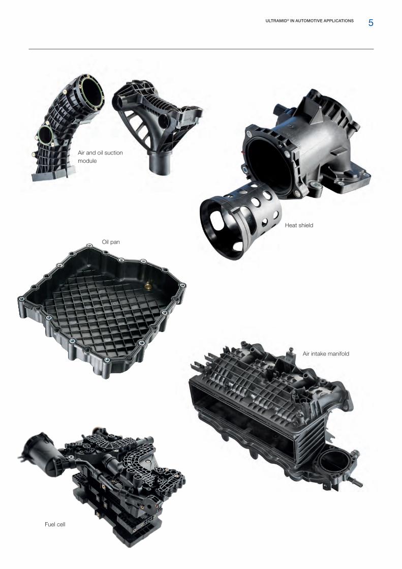
Ultramid® in automotive applications
ULTRAMID® IN AUTOMOTIVE APPLICATIONS
Automotive engineering demands very high quality and safety standards; this is also reflected in the continually increasing demands on the materials used. Ultramid® products possess very good thermal and chemical stabil-ity, static and dynamic strength, impact resistance and good long-term performance. These technical properties make them particularly suitable for use in a wide range of automobile components.
The development of Ultramid® products keeps pace with new drive concepts, advances in electrification and trends such as autonomous driving, making it possible to create new components.
Ultramid® products also help to satisfy other requirements for lightweight construction and recyclability.
The comprehensive Ultramid® product range allows cus-tomers to select the most appropriate products, enabling them to manufacture components and assemblies eco-nomically and competitively.
High-voltage connector
Gearbox control unit
5ULTRAMID® IN AUTOMOTIVE APPLICATIONS
Air and oil suction module
Air intake manifold
Oil pan
Heat shield
Fuel cell
6
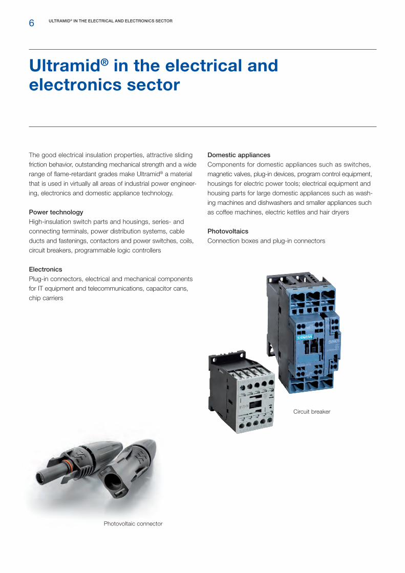
Ultramid® in the electrical and electronics sector
ULTRAMID® IN THE ELECTRICAL AND ELECTRONICS SECTOR
The good electrical insulation properties, attractive sliding friction behavior, outstanding mechanical strength and a wide range of flame-retardant grades make Ultramid® a material that is used in virtually all areas of industrial power engineer-ing, electronics and domestic appliance technology.
Power technology
High-insulation switch parts and housings, series- and connecting terminals, power distribution systems, cable ducts and fastenings, contactors and power switches, coils, circuit breakers, programmable logic controllers
Electronics
Plug-in connectors, electrical and mechanical components for IT equipment and telecommunications, capacitor cans, chip carriers
Circuit breaker
Domestic appliances
Components for domestic appliances such as switches, magnetic valves, plug-in devices, program control equipment, housings for electric power tools; electrical equipment and housing parts for large domestic appliances such as wash-ing machines and dishwashers and smaller appliances such as coffee machines, electric kettles and hair dryers
Photovoltaics
Connection boxes and plug-in connectors
Photovoltaic connector

7ULTRAMID® IN THE ELECTRICAL AND ELECTRONICS SECTOR
Terminal strip
Power electronics
Switch gear

8
Design chairs
Ultramid® for industrial products and consumer goods
High mechanical strength combined with good toughness and, in particular, the possibility for customization of prod-ucts make Ultramid® suitable for a wide variety of applica-tions in consumer goods and industrial products.
These are mainly applications demanding high mechanical properties in order to replace traditional materials such as metals by plastics with tailor-made properties. Ultramid® products also benefit from good chemical stability and easy colorability. Additionally, special Ultramid® products are used in applications in which regulatory requirements for drinking water and food contact are necessary.
ULTRAMID® FOR INDUSTRIAL PRODUCTS AND CONSUMER GOODS
The varied and in some cases tailor-made properties result in broad application fields such as:
Structural and installation engineering Wall and facade dowels, fixing elements for facades and in solar technologies, thermal insulation profiles for windows
Sanitary services Handles, brackets, fixtures, fans, flow water heaters, fittings, water meter housings
Household Seating, chair castors and bases, furniture fittings, power tools, domestic appliances, sport and leisure equipment
General mechanical and apparatus engineering Ball bearing cages, gears and gear wheels, seals, flanges, connectors, screws, sliding components
Materials handling Rollers, pulleys, bearing bushes, transport containers, conveyor belts, conveyor chains

9ULTRAMID® FOR INDUSTRIAL PRODUCTS AND CONSUMER GOODS
Ski binding
Cooking set
Ax handle
Dowels
Frames for office chairs
Multi-Wing

10
Product range
Ultramid® is the trade name for the polyamides supplied by BASF for injection molding and extrusion. The product range includes PA66 grades (Ultramid® A), PA6 grades (Ultramid® B), semi-aromatic polyamides (Ultramid® T, Ultramid® Advanced N, T1000, T2000), specialty polyam-ides (Ultramid® D), PA610 (Ultramid® S Balance) and spe-cial grades based on special copolyamides. Ultramid® A is produced by condensation polymerization of hexamethylene diamine and adipic acid, Ultramid® B by hydrolytic polymer-ization of caprolactam. These materials are obtained from petrochemical feedstocks such as benzene, cyclohexane and p-xylene.
Many products are reinforced with glass fibers or other fillers and contain special additives to improve toughness, flame-retardant properties or resistance to environmental influences in order to allow a wide range of different properties. Ultramid® Advanced and Ultramid® S Balance also have other advantages, such as higher dimensional stability or chemical stability.
ULTRAMID® PRODUCT RANGEProduct range
The most important characteristics of Ultramid® are:
High strength and rigidity Very good impact strength Good elastic properties Outstanding resistance to chemicals Dimensional stability Low tendency to creep Exceptional sliding friction properties Simple processing
The basis of the Ultramid® grades are polyamides which are supplied in a variety of molecular weights or viscosities, have a range of additives and are reinforced with glass fibers or minerals. More detailed information on the individual products can be found in the Ultramid® product range and the tables 1, 2 and 3.
The Ultramid® range comprises the following groups of
products:
Ultramid® Ain its unreinforced state, is an extremely rigid, abrasion-resis-tant, heat resistant and hard material. It is one of the pre-ferred materials for parts subject to mechanical and thermal stresses in electrical, mechanical and automotive engineering.
Ultramid® Bin its unreinforced state, is a tough, hard material affording parts with good damping characteristics and high shock resistance even in dry state and at low temperatures. It is particularly tough and easy to process. Translucent products are also available under the name Ultramid® Vision.
Ultramid® product range
CEE connector

11ULTRAMID® PRODUCT RANGEProduct range
Table 1: Ultramid® base polymers
Ultramid® Cis the name given to copolyamides made from PA6 or PA66 elements that exhibit different melting points or a lower crystallinity according to their composition.
Ultramid® Dare blends of PA6 or PA66 and other polyamides with cus-tomized properties, available as unreinforced grades (e.g. Ultramid® Deep Gloss D3K) and reinforced grades (e.g. Ultramid® Endure D3G10 BK20560).
Ultramid® S Balanceis particularly resistant to chemicals and is also known for its low moisture absorption. Ultramid® S Balance is preferably used in components that come into contact with media.
Ultramid® Structure LFXis a long glass fiber-reinforced polyamide providing a high degree of stiffness at high temperatures. It shows signifi-cantly lower creep, particularly at higher temperatures, very good fatigue strength and significantly improved notched impact strength, especially at low temperatures down to -30 °C. Further information can be found in the Ultramid® Structure LFX brochure.
Ultramid® Thas a semi-aromatic structure and is a highly rigid material with a high melting point, known for its dimensional stability, high chemical resistance and constant mechanical proper-ties covering a wide range of different applications.
Ultramid® Advanced T1000has a very high, constant stiffness and strength over a tem-perature range of -40 °C to over 80 °C. It is resistant to high temperatures and against aggressive media.
Ultramid® Advanced T2000is a polyphthalamide providing good E&E performance with a high melting point, low water absorption, good mechani-cal properties at high temperatures and good chemical resistance.
Ultramid® Advanced Nis characterized by very low water absorption, excellent chemical resistance and good mechanical properties at high temperatures in conditioned state.
Glass-fiber reinforced Ultramid® These materials are distinguished by high mechanical strength, hardness, rigidity, thermostability and resistance to hot lubri-cants and hot water. Parts made from them show dimensional stability and high creep strength. Glass fiber-reinforced Ultramid® T also has extraordinarily high heat distortion temperature (up to 280 °C).
Reinforced and unreinforced grades with flame retardantsThe specially modified grades Ultramid® C3U, A3X2G5, A3X2G7, A3X2G10, B3U50G6, A3U42G6, B3UG4, B3U30G6 and T KR 4365 G5 are particularly suitable for electrotechnical components with higher fire protection requirements and high tracking resistance.
Mineral- and glass bead-filled Ultramid® Materials filled with minerals and glass beads show increased rigidity, good dimensional stability, low tendency to warp, optically appealing surfaces, partly excellent ability for metallizing and good flow characteristics.
Ultramid® Polyamide Chemical structure Melting point [°C]
Ultramid® A 66 basis hexamethylene diamine, adipic acid 260
Ultramid® B 6 polycaprolactam – NH (CH2)5CO 220
Ultramid® C 66 /6 basis hexamethylene diamine, adipic acid, caprolactam 242
Ultramid® S Balance 610 basis hexamethylene diamine, sebacic acid 222
Ultramid® T 6T / 6copolymer of caprolactam hexamethylene diamine and tere-phthalic acid
295
Ultramid® Advanced N 9T basis nonane diamine, terephthalic acide 300
Ultramid® Advanced T1000 6T/6I basis hexamethylene diamine, terephthalic acid, isophthalic acid 325
Ultramid® Advanced T2000 6T/66 basis hexamethylene diamine, terephthalic acid, adipic acid 310

12
Ultramid® A F1) W2)
Injection molding grades (unrein-forced)
A3K √easy flowing, fast processing
A3W
A4K √medium viscosity, high impact strength even at dry state
A4H
A3Z high impact strength even at dry state and low temperatures
A3...Z2/Z3/Z4 √ medium to highest level of toughness, fast processing
Special product
A3K FC Aqua® with material approvals for drinking water or food contact
Injection molding grades (rein-forced)
A3E...G3/G5/G6/G7/G10 √ good dielectric properties
A3H...G2/G5/G7/G10high heat-aging resistance even in contact with lubricants combined with good dielectric properties
A3W...G3/G5/G6/G7/G10 very high heat-aging resistance
A3Z...G3/G6 high impact strength even at dry state and low temperatures
A3K6glass bead reinforcement to achieve high dimensional stability, low warpage, and good surface appearance
A3WGM53glass and mineral reinforced grade with medium rigidity and strength as well as low warpage
Special products
A3E...G6/G7 FC Aqua® with material approvals for drinking water or food contact
A3E...G6/G7 EQ meets special purity requirements for sensitive applications in electronic industry
A3EG6 LT laser transparent black material for laser welding
A3WG6 LT laser-transparent, black material with very high heat-aging resistance for laser welding
A3HG6 Balance with improved hydrolysis resistance and special stress cracking resistance
A3HG6 HR with improved hydrolysis resistance
A3W...G6/G7 HRX with further improved hydrolysis resistance
A3HG6 WIT suited for processing by water injection technology (WIT)
A3W2...G6/G7/G10 with further improved heat-aging resistance
A3W3…G7with further improved heat-aging resistance, especially suitable for plastic air intake manifolds
A3W...G7/G10 HP with good flow and surface properties
A3WC4 with carbon fiber reinforcement for high-rigidity applications
Structure A3W...G8/G10 LFX with long glass fiber reinforcement
Structure A3EG12 LFX with long glass fiber reinforcement
Ultramid® B
Injection molding grades (unrein-forced)
B3K √
easy flowing, fast processing, high impact resistance in the conditioned stateB3S √
B3W
B35W medium viscosity, stabilized against heat-aging
B3L √ high impact strength even at dry state
B3...Z1 / Z2 / Z4 √high impact strength even at dry state
B35WZ4
Special products
B3S HP demolding optimized to achieve very fast cycle time
B3Z4 HPhigh impact strength even at dry state, optimized demolding to achieve fast cycle times
Injection molding grades (rein-forced)
B3…G3/G4/G6/G7/G8/G9/G10 √ fiber-reinforced products
B3E…G3/G4/G5/G6/G7/G8/G10 √ good dielectric properties
B3E2...G3/G6/G9 √ UV-stabilized to match requirements for automotive interior
B3H…G7/G8/G10high heat-aging resistance even in contact with lubricants combined withgood dielectric properties
B3W…G3/G5/G6/G7/G8/G10 very high heat-aging resistance
ULTRAMID® PRODUCT RANGEProduct range

13
Ultramid® B F1) W2)
Injection molding grades (rein-forced)
B3WG6 GPXwith further improved heat-aging and burst pressure resistance, especially suitable for plastic air intake manifolds
B3Z...G3/G6/G7/G8/G9/G10 high impact strength even at dry state and low temperatures
B3GK24 √ glass-fiber and glass-beads reinforced, low warpage
B3…K3 /K6√
glass-bead reinforced to achieve high dimensional stability, low warpage and good surface appearance
B3W...GM24/GM35 /GM45 glass-fiber and mineral reinforced with medium to high rigidity and strength, low warpage
B3WGM24 HPglass-fiber and mineral reinforced with medium to high rigidity and strength, low warpage and optimized demolding for fast cycle times
B3WM8miner filler for optimized surface appearance and low warpage, especially for electroplating processes
B3...M6 / M8 mineral filled, with medium rigidity and strength, low warpage
Special products
B3E…G4/G6/G8/G10 SI surface improved for excellent visual appearance and smoothness
B3EG6 EQmeets the special demands on purity for sensitive applications in the electronics industry
B3W…G6 /G7/G8 /G12 High Speed excellent flow properties and fast cycle times
B3WG6 GIT suited for processing for gas injection technology (GIT)
B3WG6 SF suitable for physical foaming processes
Structure B3W...G10 LFX with long glass fiber reinforcement
Ultramid® D
Injection molding grades (rein-forced)
D3EG10 FC Aqua® high stiffness and low water absorption, with material approvals for drinking wateror food contact
Endure D3…G7/G10 very high level of heat-aging resistance
Structure D3E…G10 /G12 LFX with long glass fiber reinforcement
Structure D3E…G8 SI LFX with long glass fiber reinforcement and improved surface quality
Blow molding grades (rein-forced)
Endure B5G3 BM highest heat-aging resistance, e. g. for parts in the charge air duct
Ultramid® S
Injection molding grades (unrein-forced)
S3W Balance easy flowing, fast processing
S3Z4 Balance impact-modified, especially suitable for applications within the sports and leisure industry
S3Z5 Balance impact-modified, especially suitable for applications within the sports and leisure industry
Injection molding grades (rein-forced)
S3EG6 Balance good dielectric properties
S3WG6 Balance excellent heat-aging and hydrolysis resistance
Ultramid® T
Injection molding grades (unrein-forced)
T KR 4350 easy flowing, fast processing
Injection molding grades (rein-forced)
T KR 4355…G5/G7/G8/G10 fiber-reinforced products
T KR 4357 G6 fiber-reinforced and impact-modified
Special products
T KR 4355 G5 LS especially suitable for laser markable parts
Ultramid® Advanced T1000
Spritzgusstypen (verstärkt)
T1000H...G7/G10high stiffness and strength up to over 80 °C and in conditioned state, resistant against aggressive media
Ultramid® Advanced N
Spritzgusstypen (unverstärkt)
N4H dimensionally stable and resistant, also against wear and abrasion
Spritzgusstypen (verstärkt)
N3HG6 high flowability, for E&E applications, JEDEC class 1
N4WG7high toughness, excellent resistance against heat and chemicals, for automotive applications
Table 2: Ultramid® product range1) Available in different colors (apart from black and natural)2) Level of heat stability:
low high
ULTRAMID® PRODUCT RANGEProduct range

14
Emergency switch
Product UL 94RTIelec
d=1.5 mm
GWIT ≥ 775GWFI ≥ 850 d = 1.5 mm
Halogen- free flame retardant Symbol
Electrical household ap-
pliancesTerminal blocks Connectors
Circuit breakers
Low-voltage switch gears Photovoltaics
Automotive construction
Railway vehicles
Ultramid® unreinforced A3K R01 V-2, 0.4 125 °C + +1) PA66
A3U32 V- 0, 0.25 130 °C + + (PA66-Blend) FR(30)
C3U V- 0, 0.4 120 °C + + PA66/6 FR(30)
B3S R03 V-2, 0.8 130 °C + +1) PA6
Ultramid® reinforced A3UG5 V-0, 0.75 120 °C + PA66 GF25 FR(40)
A3U42G6 V-0, 0.4 150 °C + (PA66-Blend) GF30 FR(40)
A3X2G5 V-0, 0.8 120 °C + PA66 GF25 FR(52)
A3XZG5 V-0, 1.5 120 °C + PA66-I GF25 FR(52)
A3X2G7 V-0, 0.75 115 °C + PA66 GF35 FR(52)
A3X2G10 V-0, 1.5 115 °C + PA66 GF50 FR(52)
B3UG4 V-2, 0.71 140 °C + PA6 GF20 FR(30)
B3U30G6 V-2, 0.75 140 °C + PA6 GF30 FR(30)
B3U50G6 V-0, 0.8 150 °C + + PA6 GF30 FR(5x)
B3UGM210 V-0, 1.5 130 °C + PA6 GF10 M50 FR(61)
T KR4365 G5 V-0, 0.75 140 °C + + PA6T/6 GF25 FR(52)
T KR4340 G6 V-0, 0.4 160 °C + + PA6T/6 GF30 FR(40)
Ultramid® Advanced reinforced N3U40G6 V-0, 0.25 120 °C + + PA9T GF30 FR(40)
Table 3: Overview of reinforced and unreinforced grades with flame retardants 1) Product does not contain flame-retardant additive
ULTRAMID® PRODUCT RANGEProduct range

15
Terminal blocks
Water meter housing
Product UL 94RTIelec
d=1.5 mm
GWIT ≥ 775GWFI ≥ 850 d = 1.5 mm
Halogen- free flame retardant Symbol
Electrical household ap-
pliancesTerminal blocks Connectors
Circuit breakers
Low-voltage switch gears Photovoltaics
Automotive construction
Railway vehicles
Ultramid® unreinforced A3K R01 V-2, 0.4 125 °C + +1) PA66
A3U32 V- 0, 0.25 130 °C + + (PA66-Blend) FR(30)
C3U V- 0, 0.4 120 °C + + PA66/6 FR(30)
B3S R03 V-2, 0.8 130 °C + +1) PA6
Ultramid® reinforced A3UG5 V-0, 0.75 120 °C + PA66 GF25 FR(40)
A3U42G6 V-0, 0.4 150 °C + (PA66-Blend) GF30 FR(40)
A3X2G5 V-0, 0.8 120 °C + PA66 GF25 FR(52)
A3XZG5 V-0, 1.5 120 °C + PA66-I GF25 FR(52)
A3X2G7 V-0, 0.75 115 °C + PA66 GF35 FR(52)
A3X2G10 V-0, 1.5 115 °C + PA66 GF50 FR(52)
B3UG4 V-2, 0.71 140 °C + PA6 GF20 FR(30)
B3U30G6 V-2, 0.75 140 °C + PA6 GF30 FR(30)
B3U50G6 V-0, 0.8 150 °C + + PA6 GF30 FR(5x)
B3UGM210 V-0, 1.5 130 °C + PA6 GF10 M50 FR(61)
T KR4365 G5 V-0, 0.75 140 °C + + PA6T/6 GF25 FR(52)
T KR4340 G6 V-0, 0.4 160 °C + + PA6T/6 GF30 FR(40)
Ultramid® Advanced reinforced N3U40G6 V-0, 0.25 120 °C + + PA9T GF30 FR(40)
Main field of application Other fields of application
ULTRAMID® PRODUCT RANGEProduct range

16
Semi-aromatic polyamides (PPA)
BASF offers a portfolio of polyphthalamides (PPA) based on four PPA polymers and comprising more than 50 com-pounds, which are described in more detail in separate brochures. The PPA portfolio includes Ultramid® Advanced N (PA9T), Ultramid® Advanced T1000 (PA6T/6I), Ultramid® Advanced T2000 (PA6T/66) and Ultramid® T (PA6T/6). The PPA portfolio is globally available and is complemented by the BASF simulation tool Ultrasim® and extensive experi-ence in application development.
Ultramid® Advanced N
A high-performance polyphthalamide with constant mechanical properties up to 100 °C (glass transition temperature: 125 °C) combined with outstanding chemical resistance, low water absorption and good tribological properties. The material permits a wide processing window and short cycle times. Parts made of Ultramid® Advanced N are lighter, smaller and stronger. The material can solve a wide range of application problems: Ultramid® Advanced N is suitable for small con-nectors and functionally integrated housings in domestic appliances, consumer electronics and mobile devices. It can be used in automotive and structural parts near the engine and the transmission system, which are in contact with hot, aggressive media and different fuels. Ultramid® Advanced N can also be used in applications such as gear wheels and other wear parts.
Further information can be found in the Ultramid® Advanced N brochure.
ULTRAMID® PRODUCT RANGESemi-aromatic polyamides (PPA)
Ultramid® Advanced T1000
Within the Ultramid® family, Ultramid® Advanced T1000 is the strongest and stiffest product group. It has consistent mechanical properties at temperatures of up to 120 °C (dry) and up to 80 °C (conditioned). Thanks to its semi-aromatic chemical structure, it shows low water absorption and is highly resistant to aggressive media. Ultramid® Advanced T1000 can be used in the automotive industry, particularly in areas where materials have to remain strong to whatever temperatures or climates they are exposed to; it can also be used in all other industries which require dimensional stabil-ity or resistance to chemicals, e.g. thermostat housings and water pumps, in vehicle fuel systems, exhaust gas recircula-tion, actuators and clutch components, in coffee machines, furniture fittings and in structural applications such as water distributors, heating systems and pumps.
Further information can be found in the Ultramid® Advanced T1000 brochure.
Gear wheels

17
Fig. 1: Tensile strength of Ultramid® T compared to PA66 at 23 °C, different moisture contents
0 1 2 3 4
Tens
ile s
tren
gth
[MP
a]
220
200
180
140
160
100
120
80
Moisture content [%]
Ultramid® Advanced T2000
A polyphthalamide combining excellent mechanical, insula-tion and dielectric properties at high temperatures. Due to its semi-aromatic chemical structure, Ultramid® Advanced T2000 is the ideal solution for components that require a high degree of consistent stiffness and strength over a wide temperature range, combined with heat resistance, low moisture uptake and optional flame retardance. The PPA has the same level of impact resistance as standard PA66 and lower water absorption than aliphatic standard polyam-ides, which gives it a high degree of dimensional stability. The high melting point (310 °C) and high heat resistance (> 280 °C, HDT-A) make it a suitable material for lead-free soldering, while preventing component deformation. It can therefore be used to manufacture sensitive connectors, structural components in laptops and circuit breakers.
Further information can be found in the Ultramid® Advanced T2000 brochure.
Ultramid® T
The partially aromatic polyamide Ultramid® T has outstanding properties: Dimensional stability even at higher temperatures (melting point: 295 °C) Excellent stiffness and strength Mechanical properties uncompromised by external conditions Toughest of all partially aromatic polyamides Low shrinkage and warpage Slow water absorption Good chemical resistance Excellent electrical properties
ULTRAMID® PRODUCT RANGESemi-aromatic polyamides (PPA)
The highly glass fiber-filled grades are particularly suitable as a substitute for metal because of their high mechanical strength.
Mechanical propertiesIn comparison to conventional polyamides (e. g. PA6 or PA66), Ultramid® T is noted for its much slower water absorption. Furthermore, moisture absorption does not result in any significant change to the mechanical proper-ties at room temperature because of the basically higher glass transition temperature of Ultramid® T.
T KR 4355 G7 PA66 – 35 % GF

18 ULTRAMID® PRODUCT RANGESemi-aromatic polyamides (PPA)
Semi-aromatic polyamides are generally not the toughest materials. Because of its molecular structure, Ultramid® T has significantly higher impact resistance values than other semi-aromatic polyamides (Fig. 2) and does not loose its impact resistance in cold environments or in the dry state. Due to its excellent toughness in cold environments and in dry state, Ultramid® T is ideally suited, e. g. as material for plugs and connectors.
Chemical resistanceLike all polyamides, Ultramid® T also shows excellent chemi-cal resistance. The material also offers other advantages compared to polar substances such as alcohols and aqueous calcium and zinc chloride solutions. Moreover, the strength and rigidity reduction and the change in vol-ume are much lower with Ultramid® T than with a PA6.
Shrinkage and warpageProducts based on Ultramid® T show lower shrinkage in the longitudinal and transverse direction in comparison to PA66. Depending on the component geometry, this leads to extremely low warpage. In addition, as a result of the slow water absorption compared with standard polyamides, components made from Ultramid® T have significantly higher dimensional stability under different external conditions.
Impa
ct s
tren
gth
[kJ/
m2]
100
80
60
40
20
0Ultramid® T PPS
Fig. 2: Impact strength (23 °C) of Ultramid® T compared to PPS (glass fiber content: 30-35 %)
Fuel pressure sensor

19
Quick connector
Fig. 3: Hydrolysis resistance of Ultramid® S Balance compared with PA66, in Glysantin® / water (1:1) at 130 °C
Str
ess
at b
reak
at 2
3 °C
[MP
a]
Time [h]
2000150010005000
40
80
120
200
160
Ultramid® S Balance
As a long-chain polyamide, Ultramid® S Balance has the following properties:
Good hydrolysis resistance High stress cracking resistance Low water absorption, high dimensional stability Mechanical properties largely independent of the level of conditioning
Among long-chain polyamides, Ultramid® S Balance has one of the highest level of rigidity and strength. This makes it the material of choice in areas that require a combination of resistance to media and the mechanical properties of conventional materials like PA6 and PA66.
Mechanical properties
The lower water absorption of Ultramid® S Balance com-pared to PA6 or PA66 results in constant mechanical prop-erties under changing climatic conditions. Furthermore, Ultramid® S Balance has a higher heat-aging resistance compared to PA12 and thus offers a balanced range of properties for a variety of applications.
Chemical and hydrolysis resistance
Like all polyamides, Ultramid® S Balance shows excellent chemical resistance. In addition, this material also offers a number of other advantages, e. g. increased hydrolysis resis-tance compared with PA6 or PA66. This makes Ultramid® S Balance the perfect material for plug-in connectors, pipes and vessels in cooling circuits. The material can also be used in fuel applications, such as quick connectors.
Stress cracking resistance due to the presence of zinc chloride is an important requirement for car exteriors. Due to their inherent molecular structure, long-chain polyam-ides have a clear advantage. For instance, glass-fiber rein-forced Ultramid® S Balance meets the conditions of the standards SAE 2644 and FMVSS 106. This means that the material is particularly suited to the overmolding of metal and electronic components that come into contact with aggressive media, e. g. wheel speed sensors.
ULTRAMID® PRODUCT RANGEUltramid® S Balance
PA66 GF30 HR S3WG6 Balance

20
Ultramid® Vision
With Ultramid® Vision, BASF has succeeded for the first time in developing a semi-crystalline polyamide that allows light to pass through largely unhindered. Compared to opaque standard polyamides, Ultramid® Vision displays very high light transmission with low light scattering.
The new polyamide combines the best properties of two groups of materials: The chemical resistance, temperature resistance and easy processing of semi-crystalline, opaque materials and
The translucence of amorphous polymers at a competitive price.
Ultramid® Vision thus represents a cost-efficient material solution for applications in chemically challenging environ-ments that require a high level of light transmission or even translucency.
The free colorability with suitable dyes makes it possible to achieve luminous color effects that offer a wide range of design possibilities. In addition, the translucent Ultramid® Vision can be combined with other polyamide materials in a multi-component injection-molding process, allowing multi-functional parts with translucent or illuminated areas to be manufactured easily.
If components manufactured from Ultramid® Vision are exposed to higher temperatures and moisture, the haze and transmission values barely change compared to the initial state. The translucent polyamide also has a convincing combination of high UV resistance, scratch resistance and outstanding chemical stability.
Beyond the uncolored base-grade Ultramid® Vision B3K UN, specially equipped products with diffuse light transmis-sion (DLT) at high transmission rate as well as products colored according to customer requests can also be manu-factured. The Ultramid® Vision portfolio therefore offers designers and developers a broad range of possibilities for realizing design features and lighting elements in car interi-ors and various consumer and industrial applications.
Design discs
ULTRAMID® PRODUCT RANGEUltramid® Vision
Fig. 4: Haze values of Ultramid® B3S UN and Ultramid® Vision B3K UN as function of the wall thickness
Haz
e [%
]
Wall thickness [mm]
2.52.01.51.00.50
20
40
60
100
80
B3S UN Vision B3K UN

21
Ultramid® Deep Gloss
Ultramid® Deep Gloss is the specialty polyamide for high-gloss components in automobile interiors. The balanced property profile of Ultramid® Deep Gloss makes it the ideal solution for visual appealing and yet durable parts without any additional painting steps.
High gloss Excellent scratch resistance High chemical stability Low emissions Good UV resistance
Because of its balanced property profile, Ultramid® Deep Gloss is the ideal material for: Decorative parts, e.g. the edges of displays Decorative trim around lights Headliner pockets Functional components e.g. air vents Inserts in vehicle doors or center consoles
Special additives provide the properties required to ensure the durability of high-quality surfaces, such as scratch and abrasion resistance and sufficiently high UV resistance.
Ultramid® Deep Gloss accurately reproduces every detail of structures without the need for variothermal mold tempera-ture control. This offers designers new possibilities for com-bining high gloss surfaces with unique textures.
In addition to the glossy deep black main product, it is also possible to realize other colors and the latest color trends. Ultramid® Deep Gloss has been developed primarily to sat-isfy the requirements of automobile interiors. But it is also possible to produce components with similar demands in the consumer goods sector.
Demonstrator
ULTRAMID® PRODUCT RANGEUltramid® Deep Gloss
DIN 75202 L ΔE Greyscale Gloss 20°
0 h 2.77 0 5 91.4 GU
280 h (4 Cycles) 2.98 0.31 4 - 5 94.3 GU
420 h (6 Cycles) 3.41 0.73 4 74.8 GU
Table 4: Accelerated aging test of Ultramid® Deep Gloss
1,2 W/m2 @ 420 nmStandard black: 100 °C; 20 % r. h.
Demonstrator

22 THE PROPERTIES OF ULTRAMID®
Mechanical properties
Mechanical properties
The Ultramid® A (PA66) and Ultramid® B (PA6) grades, which are described here offer various combinations of mechanical properties and thus meet a variety of requirements, for example from the E & E and automotive industries as well as from numerous other sectors.
Special about polyamide as a material is its ideal combina-tion of strength, rigidity and toughness together with excel-lent longevity across a wide temperature range. These advantages can be attributed to the partially crystalline structure of the polyamide: strong hydrogen bonds between molecules give strength to the crystalline areas and allow high operating temperatures, while more flexible molecule chains in the amorphous regions ensure exceptional tough-ness.
When choosing materials on the basis of key mechanical data, one special feature of the polyamide must be taken into account: freshly molded components are always dry and will absorb moisture depending on the ambient conditions. This leads to a considerable change in key mechanical properties, particularly in typical test conditions of 23 °C. This is why in the data sheets a distinction is frequently made between the key material data “dry” and “conditioned”.
Fig. 5 shows unreinforced Ultramid® A3K to demonstrate the influence of conditioning on the tensile modulus of elasticity (shift in the glass transition temperature). Ultramid® A3EG10, a 50 % glass fiber-reinforced product, has a reduced mois-ture uptake (compared with an unreinforced grade) as mois-ture is only taken up by the amorphous part of the PA matrix.
In the following part, the mechanical properties of the Ultramid® range are described on the basis of dry test specimens.
Tens
ile m
odul
us [G
Pa]
22
24
26
20
18
16
14
12
10
8
6
4
2
0-50 -25 0 25 50 75 100 125 150
Temperature [°C]
Fig. 5: Modulus of elasticity for selected Ultramid® grades as function of temperature and conditioning
The properties of Ultramid®
A3K (conditioned, 2.8 % moisture) A3K (dry) A3EG10 (conditioned,1.2 % moisture) A3EG10 (dry) B3WG12 HSP (conditioned, 1,35 % moisture) B3WG12 HSP (dry)

23THE PROPERTIES OF ULTRAMID®
Mechanical properties
Fig. 8: Tensile stress (yield stress in the case of unreinforcedgrades) for Ultramid® grades as a function of moisture con-tent at 23 °C (ISO 527)
Elo
ngat
ion
at b
reak
/yie
ld s
tres
s [M
Pa]
Moisture content [%]
9
20
220
200
180
160
140
120
100
80
60
40
0 1 2 4 73 65 8
Temperature 23 °C
A3EG7 A3EG5 B3EG6 A3K B3S
Yield stress / Tensile stress [MPa]
Fig. 6: Yield stress (tensile stress in the case of reinforced grades) for selected Ultramid® grades at 23 °C, dry (ISO 527)
200 25015010050
Modulus of elasticity [MPa]
5000 10000 15000 20000
Fig. 7: Modulus of elasticity for selected Ultramid® grades at 23 °C, dry (ISO 527)
A3EG10
T KR 4355 G7
A3EG7, B3ZG8
A3EG6
B3WGM24, B3EG6, B3ZG6
A3EG5, A3HG5, B3EG5
B3EG3, B3ZG3
B3M6
B3S
A3K, A3W
A3R, B3L
B3WG12
T KR 4355 G10
A3EG10, A3WG10
T KR 4355 G10
B3WG12
T KR 4355 G7
A3EG7, B3G8
A3EG6, A3X2G10, B3EG6
A3EG5, A3X2G7, B3EG5, B3ZG6
A3X2G5
B3EG3
B3WGM24
T KR 4350
A3K, B3S
B3M6
A3R
B3L
A3Z
The product range can be divided into six groups according to the range of the modulus of elasticity (dry):
Impact-modified unreinforced grades 1500 - 2000 MPa
Unreinforced grades 2700 - 3500 MPa
Mineral-filled, impact-modified grades (+GF) 3800 - 4600 MPa
Mineral-filled grades (+GF) 3800 - 9300 MPa Impact-modified, glass-fiber reinforced grades 5200 - 11200 MPa
Glass-fiber reinforced grades 5200 - 21100 MPa
The mechanical properties depend on various factors like testing temperature, moisture content, storage time (post-crystallization) and the molding conditions of the respective test specimens.

24 THE PROPERTIES OF ULTRAMID®
Mechanical properties
Fig. 10: Shear modulus of Ultramid® B grades as a function of temperature and filler, according to ISO 6721-2, dry
250200150100500100
101
102
103
She
ar m
odul
us [M
Pa]
-50
Temperature [°C]
B3K B3M6 B35EG3 B3EG6
Fig. 11: Flexural modulus of reinforced Ultramid® A grades as a function of temperature (ISO 178 flexural strength test, dry)
Flex
ural
mod
ulus
[MP
a]
Temperature [°C]
1601401201008060402000
2000
4000
6000
8000
10000
12000
14000
16000
-40 -20
A3WG10, A3EG10 A3WG7, A3EG7 A3WG5, A3EG5,
A3HG5
Fig. 12: Flexural modulus of reinforced Ultramid® B grades as a function of temperature (ISO 178 flexural strength test, dry)
Flex
ural
mod
ulus
[MP
a]
Temperature [°C]
1601401201008060402000
2000
4000
6000
8000
10000
12000
14000
16000
-40 -20 12000
B3WG6, B3EG6 B3WG5 B3EG3, B35EG3 B3WGM24 B3M6
Fig. 9: Shear modulus of Ultramid® A grades as a function of temperature and glass fiber content according to ISO 6721-2, dry
She
ar m
odul
us [M
Pa]
Temperature [°C]
300250200150100500100
101
102
103
-50
A3K A3WG3 A3EG6 A3EG10

25THE PROPERTIES OF ULTRAMID®
Mechanical properties
In the case of the reinforced grades, the specific filler has a pronouced influence on the properties. The most important modification is the reinforcement with glass fibers. Influ-encing factors are: glass fiber content, average glass fiber length, glass fiber length distribution and the glass fiber orientation. The latter is caused by the flow process of the melt and results in anisotropic material properties. These effects can be calculated quantitatively with the BASF simulation tool Ultrasim® for the purpose of optimizing part design.
The behavior under short-term uniaxial tensile stress is shown as a stress strain diagram (Fig. 13 and 14), which illustrates the influence of temperature and reinforcement. The values shown originate from uncolored products and may be influenced by coloring. The yield stress of unrein-forced Ultramid® ranges from 70 to 100 MPa while the stress at break for reinforced grades reaches up to 250 MPa.
Impact strength, low-temperature impact strength
Polyamides are very tough materials. They are suitable for parts required to exhibit high resistance to fracture. Standard test values generally determined under different conditions are used to characterize their impact behavior (see the Ultramid® product range).
Although the values are not directly comparable with one another due to the differing test setups, test specimen dimensions and notch shapes, they do allow comparison of molding materials within the individual product groups.Tests on finished parts are indispensable for the practical assessment of impact behavior. However, the behavior of Ultramid® grades when subjected to impact is affected by many factors, of which the most important are the shape of the part, the rigidity of the material and the moisture con-tent.
The Ultramid® portfolio offers grades with different combina-tions of impact strength and rigidity. Depending on applica-tion, requirements, design and processing, products which are unreinforced, of relatively high molecular weight, glass-fiber reinforced, mineral-filled or impact modified can be selected, each having an optimum relationship between impact strength and rigidity.
Fig. 13: Stress-strain diagrams for Ultramid® B3S and B3WG5 (dry) in accordance with ISO 527
2
2
2
2
3
3
3
3
20
20
Tens
ile s
tres
s [M
Pa]
200
200
180
180
160
160
140
140
120
120
100
100
80
80
60
60
40
40
0
0
1
1
1
1
0
0
Elongation [%]
60
Fig. 14: Stress-strain diagrams for Ultramid® A3K and A3EG5 (dry) in accordance with ISO 527
Elongation [%]
100
°C
60
23
-20
100
B3WG5 B3S
°C
-20
23
Tens
ile s
tres
s [M
Pa]
A3K A3EG5
150
120
100
60
23
-20
°C
150
120100
60
23
-20
°C

26
Fig. 15: Isochronous stress-strain curves for Ultramid® A3K in accordance with ISO 899 under standard atmospheric conditions (23 / 50) and at 120 °C (in the dry state)
NK 23/50 extrapolated
120 °C extrapolated
The advice below should also be taken into account when choosing suitable materials. Moisture promotes the tough-ness of Ultramid®, even at low temperatures. In the case of glass-fiber reinforced grades the impact strength of finished parts decreases as the glass fiber content rises while strength and the values in the flexural impact test for standardized test specimens increase. This effect is caused by differ-ences in glass fiber orientation within the test specimens.
Unreinforced products of high molecular weight have proved to be effective for thick-walled engineering parts required to exhibit high impact strength.
Even in the dry state the impact-modified, unreinforced Ultramid® grades like B3L exhibit high impact strength. They are employed when conditioning or intermediate storage for absorption of moisture are uneconomic or when extremely high notched or low-temperature impact strength are reuqired.
Apart from the particular processing conditions, the geo metry of the molded part – with the resultant moments of resis-tance – and especially the wall thicknesses and the notch radii also play a major role in determining the fracture energy. Even the speed and point of impact significantly affect the results.
Behavior under long-term static loading
The static loading of a material for relatively long periods is caused by a constant stress or strain. The tensile creep test in accordance with ISO 899 and the stress relaxation test in accordance with DIN 53441 provide information about exten-sion, mechanical strength and stress relaxation behavior under sustained loading.
The results are presented as creep curves, creep modu-lus curves, creep stress curves and isochronous stress-strain curves (Figs. 15 and 16). The curves shown here are obtained at standard atmosphere according to ISO 291 and 120 °C and represent only a selection of the results from our comprehensive investigations.
Further values and diagrams for different temperatures and atmospheric conditions can be requested from the Ultra-Infopoint or in the program “Campus”. Data obtained from uniaxial tensile loads can also be used to assess the behavior of a material under multiaxial loads. Especially rein-forced grades are noted for their high creep rapture strength and low tendency to creep.
THE PROPERTIES OF ULTRAMID®
Mechanical properties
22 33
2
Tens
ile s
tres
s [M
Pa]
16
14
12
10
8
6
4
0 11 0
Elongation [%]
105 h
104 h
10 h
103 h
104 h
103 h
10 h
Fig. 16: Isochronous stress-strain curves for Ultramid® A3WG10 in accordance with ISO 899 under standard atmo-spheric conditions (23 / 50) and at 120°C (in the dry state)
2 23 3
10
Tens
ile s
tres
s [M
Pa]
100
110
90
80
70
60
50
40
30
20
0 01 1
Elongation [%]
10 h5 · 104 h
103 h104 h
10 h
103 h
104 h
NK 23/50 extrapolated
120 °C extrapolated

27
Behavior under cyclic loads, flexural fatigue strength
Engineering parts are also frequently subjected to stress by dynamic forces, especially alternating or cyclic loads, which act periodically in the same manner on the structural part. The behavior of a material under such loads is determined in long-term tests using tensile and compressive loading alternating up to very high load-cycle rates. The results are presented in Woehler diagrams, obtained by plotting the applied stress against the load-cycle rate achieved in each case (Fig. 13). When transfering the test results in practice, it has to be taken into account that at high cycle fatigue fre-quencies the test specimen may heat up considerably due to internal friction. In such cases it may make sense to apply a higher testing temperature. (Fig. 13).
THE PROPERTIES OF ULTRAMID®
Mechanical properties
Tribological behavior
The smooth, tough and hard surface, partially crystalline structure, high thermostability and resistance to lubricants, fuels and solvents make Ultramid® an ideal material for parts subjected to sliding friction.
Whereas metallic materials tend to jam under dry-running conditions, pairings with Ultramid® run satisfactorily in most cases without lubrication.
Wear and friction are system properties which depend on many parameters, e. g. on the paired materials, surface tex-ture and geometry of the sliding parts in contact, the inter-mediate medium (lubricant) and the stresses due to exter-nal factors such as pressure, speed and temperature.
The most important factors determining the level of wear due friction and the magnitude of the coefficient of sliding friction of Ultramid® are the hardness and surface rough-ness of the paired materials, the contact pressure, the distance traversed, the temperature of the sliding surfaces and the lubrication. Further information can be found in the Technical Information “Friction and wear of polymer materials”.
Cycles
Max
. str
ess
[MP
a]
100
10
Fig. 17: Fatigue of Ultramid® A3WG7 at different temperatures (dry, R = -1, 10 Hz, lengthwise oriented, thickness = 3 mm)
1000 10000 100000 1000000
23 °C 80 °C 130 °C

28
Thermal properties
Ultramid® has the following melting temperatures:Ultramid® A: 260 °CUltramid® B: 220 °CUltramid® C: 243 °CUltramid® S: 222 °CUltramid® T: 295 °CUltramid® Advanced T1000: 325 °C Ultramid® Advanced T2000: 310 °C Ultramid® Advanced N: 300 °C
Due to its semicrystalline structure and strong hydrogen bonding Ultramid® retains its shape even at elevated tem-peratures close to the melting range.
Ultramid® stands out among other partially crystalline thermo-plastics due to its low coefficients of linear expansion.
The reinforced grades in particular exhibit high dimensional stability when exposed to temperature changes. In the case of the glass-fiber reinforced grades, however, linear expansion depends on the orientation of the fibers.
Behavior on heat
Apart from its product-specific thermal properties the behav-ior of components made from Ultramid® on exposure to heat depend an many factors: Exposure time, the specific source of thermal stress and mechanical load at elevated temperature. The design of the parts also has an effect. Accordingly, the thermostability of Ultramid® parts cannot be estimated simply on the basis of the temperature values from the various standardized tests no matter how valuable the latter might be for guidance and comparisons.
The shear modulus and damping values measured as a function of temperature in torsion pendulum tests in accor-dance with ISO 6721-2 afford valuable insight into the tem-perature behavior. Comparison of the shear modulus curves (Fig. 9 and 10) provides information about the different thermo-mechanical effects at low deformation stress and speed. Based on practical experience, the thermostability of parts produced in optimum manner is in good agreement with the temperature ranges determined in the torsion tests in which the start of softening becomes apparent.
The test for heat resistance in accordance with IEC 60695-10-2 (ball indentation test), is usually specified for applica-tions in electrical equipment. All Ultramid® grades can pass this test at 125 °C, making Ultramid® the material of choice for voltage carrying parts. Higher temperature requirements can also be met with Ultramid®. We recommand reinforced grades for this purpose.
THE PROPERTIES OF ULTRAMID®
Thermal properties
Circuit breaker

29
Heat-aging resistance
Stabilized Ultramid®, with K, E, H or W as the second letter of the nomenclature, is suitable for parts subject to long periods of temperature stress. Depending on the respec-tive application requirements, the Ultramid® portfolio cov-ers the entire range of continuous operating temperatures: W2 stabilization is suitable for temperatures up to 190 °C, and W3 stabilization for temperatures up to 210 °C. The spectrum is completed by Ultramid® Endure, which can be used up to 220 °C. Optimized products with E or H stabilization are suitable for sensitive applications, e.g. in electronics.
The adjacent figure 18 summarizes the features and effec-tiveness of each stabilization. The temperature ranges are given only for guidance and depend on the particular prod-uct. The tensile strength as a function of the storage time is shown in Figure 19 for a number of Ultramid® grades.
THE PROPERTIES OF ULTRAMID®
Thermal properties
Fig. 18: Typical continuous operating temperatures (in rela-tion to the retention of tensile strength after 3,000 h) for Ultramid® grades
Temperature [°C]
130110 150 170 190 210 230
Endure
W3
W2
W
H
E
Time [h]
Tens
ile s
tren
gth
[MP
a]
Fig. 19: Heat-aging resistance of different Ultramid® grades (23 °C, dry)
250
200
150
100
50
0 500 1000 1500 2000 2500 3000
B3WG6, 150 °C A3W2G6, 190 °C A3WG7, 170 °C Endure D3G7, 220 °C A3W3G7, 210 °C

30 THE PROPERTIES OF ULTRAMID®
Water absorption and dimensional stability
Heat-aging resistance in hot lubricants, coolants and
solvents
The widespread application of Ultramid® in engineering, especially in automotive applications, e. g. in engine oil cir-cuits and gearboxes, is based on its outstanding long-term resistance to hot lubricants, fuels, coolants and to solvents and cleaning agents. Figures 20 and 21 show how the elon-gation at break of glass fiber-reinforced Ultramid® grades can be affected by storage in hot lubricants or coolants. A3HG6 HR and A3WG6 HRX are particularly suitable for parts of the vehicle cooling system, the latter one is espe-cially effective at high operating temperatures.
Water absorption and dimensional stability
A special characteristic of polyamides in comparison with other thermo plastics is their water absorption. In water or in moist air depending on its relative humidity and dependant on time, temperature and wall thickness moldings absorb a certain quantity of water so that their dimensions increase slightly. The increase in weight on saturation depends on the respective Ultramid® grade and is listed in the tables in the range chart. Fig. 22 shows how the absorption of moisture on saturation depends on the relative humidity.
Dowels
Fig. 20: Tensile strength of different Ultramid® A grades after storage in oils or lubricating greases
Fig. 21: Tensile strength of different Ultramid® grades after storage in Glysantin® / water 1:1
A3HG7, gear oil – Pentosin FFL2, 150 °C A3WG7, engine oil – Aral Extra Turboral SAE 10W-40, 150 °C A4H, lubrication grease – Fuchs Renolit LT1, 120 °C A3WG7,gear oil – Dexron VI ATF2, 150 °C
A3HG6 HR, 130 °C A3WG6 HRX, 130 °C S3WG6 Balance, 130 °C Advanced N4HG7, 135 °C
Tens
ile s
tren
gth
[MP
a]
Time [h]
250
200
150
100
50
0 500 1000 1500 2000 2500 3000
Tens
ile s
tren
gth
[MP
a]
Time [h]
250
200
150
100
50
0 400 800 1200 20001600
31
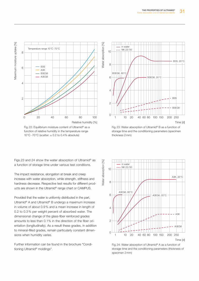
Figs. 23 and 24 show the water absorption of Ultramid® as a function of storage time under various test conditions.
The impact resistance, elongation at break and creep in crease with water absorption, while strength, stiffness and hardness decrease. Respective test results for different prod-ucts are shown in the Ultramid® range chart or CAMPUS.
Provided that the water is uniformly distributed in the part, Ultramid® A and Ultramid® B undergo a maximum increase in volume of about 0.9 % and a mean increase in length of 0.2 to 0.3 % per weight percent of absorbed water. The dimensional change of the glass-fiber reinforced grades amounts to less than 0.1 % in the direction of the fiber ori-entation (longitudinally). As a result these grades, in addition to mineral-filled grades, remain particularly constant dimen-sions when humidity varies.
Further information can be found in the brochure "Condi-tioning Ultramid® moldings".
THE PROPERTIES OF ULTRAMID®
Water absorption and dimensional stability
Fig. 22: Equilibrium moisture content of Ultramid® as a function of relative humidity in the temperature range 10 °C - 70 °C (scatter: ± 0.2 to 0.4 % absolute)
Max
imum
moi
stur
e up
take
[%]
Relative humidity [%]
8
6
4
2
0 20 40 60 80 100
Temperature range 10 °C - 70 °C
B3S A3K B3EG6 A3EG6
Fig. 23: Water absorption of Ultramid® B as a function of storage time and the conditioning parameters (specimen thickness 2 mm)
Wat
er a
bsor
ptio
n [%
]
10
6
8
4
2
0250200150100801 10 20 40 60
Time [d]
B3S, 20 °C
B3EG6, 20 °C
B3S
B3EG6
B3EG6, 80 °C
in water NK 23 / 50
Fig. 24: Water absorption of Ultramid® A as a function of storage time and the conditioning parameters (thickness of specimen 2 mm)
Wat
er a
bsor
ptio
n [%
]
10
6
8
4
2
0250200150100801 10 20 40 60
Time [d]
A3K, 20 °C
A3K
A3EG6, 80 °CA3EG6, 20 °C
A3EG6
in water NK 23 / 50

32
Brush holder
Electrical properties
The paramount importance of Ultramid® in electrical engi-neering, especially for electrical insulating parts and hous-ings in power engineering, is attributable to its good insu-lating properties (volume and surface resistance) combined with its high impact strength and creep strength as well as its advantageous properties in relation to heat-aging. As a result, Ultramid® is numbered among the high-performance insulating materials. Flame-retardant grades are always preferred where fire behavior requirements are high.
THE PROPERTIES OF ULTRAMID®
Electrical properties
Concerning electrical properties the following should be considered:
The products are characterized by a high tracking current resistance which is only slightly impaired by the moisture-content of the material.
The specific volume resistance and the surface impedance are very high; these values decline at elevated temperatures and also when the water content is relatively high.
As for all electrical insulating materials, when used in harsh conditions, continual wetting due to condensation must be prevented by appropriate design measures.
Unfavorable operating environments such as hot pockets combined with high air humidity, moist, warm conditions or poor ventilation can adversely affect the insulating properties.
For the above reasons, the performance of the components should be carefully checked for each application. The values of the electrical properties are listed in the range chart.
For reliable micro-electronics in sensitive automotive appli-cations such as control units and sensors, BASF has devel-oped a portfolio of various polyamide 6 and 66 grades that help prevent damage to circuits by electric corrosion. The different Ultramid® EQ grades (EQ = electronic quality) are extremely pure, which means they have hardly any electri-cally active or corrosion-generating contents, yet still offer good resistance to heat-aging. They are subject to special quality tests that cover raw material selection, the produc-tion process, and the analysis of the halogen content. The globally available portfolio consists of uncolored and black grades with a glass fiber content of 30 % and 35 %, which are also laser-markable.
Connector
33
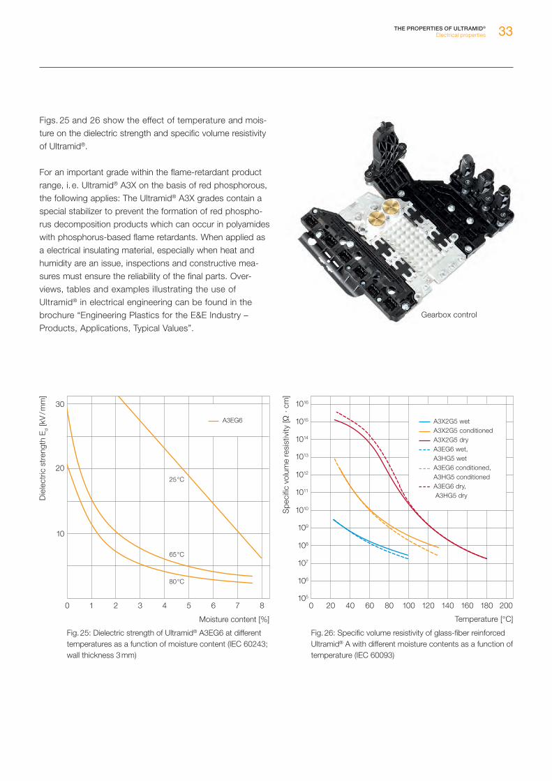
Figs. 25 and 26 show the effect of temperature and mois-ture on the dielectric strength and specific volume resistivity of Ultramid®.
For an important grade within the flame-retardant product range, i. e. Ultramid® A3X on the basis of red phosphorous, the following applies: The Ultramid® A3X grades contain a special stabilizer to prevent the formation of red phospho-rus decomposition products which can occur in polyamides with phosphorus-based flame retardants. When applied as a electrical insulating material, especially when heat and humidity are an issue, inspections and constructive mea-sures must ensure the reliability of the final parts. Over-views, tables and examples illustrating the use of Ultramid® in electrical engineering can be found in the brochure “Engineering Plastics for the E&E Industry – Products, Applications, Typical Values”.
THE PROPERTIES OF ULTRAMID®
Electrical properties
Fig. 25: Dielectric strength of Ultramid® A3EG6 at different temperatures as a function of moisture content (IEC 60243; wall thickness 3 mm)
Die
lect
ric s
tren
gth
Ed
[kV
/ mm
]
Moisture content [%]
30
20
10
0 1 2 3 4 5 6 7 8
80 °C
65 °C
25 °C
A3EG6
Gearbox control
Fig. 26: Specific volume resistivity of glass-fiber reinforced Ultramid® A with different moisture contents as a function of temperature (IEC 60093)
200 40 60 80 100 120 160 180140 200
Spe
cific
vol
ume
resi
stiv
ity [Ω
· cm
]
1016
1015
1014
1013
1012
1011
107
108
109
1010
106
105
Temperature [°C]
A3X2G5 wet A3X2G5 conditioned A3X2G5 dry A3EG6 wet, A3HG5 wet
A3EG6 conditioned, A3HG5 conditioned
A3EG6 dry, A3HG5 dry
34
Fire behavior
General notes
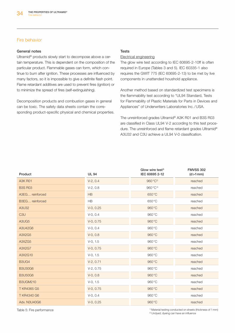
Ultramid® products slowly start to decompose above a cer-tain temperature. This is dependent on the composition of the particular product. Flammable gases can form, which con-tinue to burn after ignition. These processes are influenced by many factors, so it is impossible to give a definite flash point. Flame retardant additives are used to prevent fires (ignition) or to minimize the spread of fires (self-extinguishing).
Decomposition products and combustion gases in general can be toxic. The safety data sheets contain the corre-sponding product-specific physical and chemical properties.
Tests
Electrical engineeringThe glow wire test according to IEC 60695-2-10ff is often required in Europe (Tables 3 and 5). IEC 60335-1 also requires the GWIT 775 (IEC 60695-2-13) to be met by live components in unattended houshold appliance.
Another method based on standardized test specimens is the flammability test according to “UL94 Standard, Tests for Flammability of Plastic Materials for Parts in Devices and Appliances” of Underwriters Laboratories Inc. / USA.
The unreinforced grades Ultramid® A3K R01 and B3S R03 are classified in Class UL94 V-2 according to this test proce-dure. The unreinforced and flame retardant grades Ultramid® A3U32 and C3U achieve a UL94 V-0 classification.
THE PROPERTIES OF ULTRAMID®
Fire behavior
Product UL 94Glow wire test1) IEC 60695 2-12
FMVSS 302(d >1 mm)
A3K R01 V-2, 0.4 960 °C2) reached
B3S R03 V-2, 0.8 960 °C 2) reached
A3EG… reinforced HB 650 °C reached
B3EG… reinforced HB 650 °C reached
A3U32 V-0, 0.25 960 °C reached
C3U V-0, 0.4 960 °C reached
A3UG5 V-0, 0.75 960 °C reached
A3U42G6 V-0, 0.4 960 °C reached
A3X2G5 V-0, 0.8 960 °C reached
A3XZG5 V-0, 1.5 960 °C reached
A3X2G7 V-0, 0.75 960 °C reached
A3X2G10 V-0, 1.5 960 °C reached
B3UG4 V-2, 0.71 960 °C reached
B3U30G6 V-2, 0.75 960 °C reached
B3U50G6 V-0, 0.8 960 °C reached
B3UGM210 V-0, 1.5 960 °C reached
T KR4365 G5 V-0, 0.75 960 °C reached
T KR4340 G6 V-0, 0.4 960 °C reached
Adv. N3U40G6 V-0, 0.25 960 °C reached
Table 5: Fire performance 1) Material testing conducted on sheets (thickness of 1 mm)2) Undyed; dyeing can have an influence

35
The glass fiber-reinforced Ultramid® grades generally require a flame retardant additive to achieve a good clas-sification. Examples are Ultramid® A3X2G, A3U42G6, B3U50G6, B3U30G6 and Ultramid® Advanced N3U40G6. The flame retarding properties are summarized in Tables 3 and 5.
TransportationIn traffic and transport engineering, plastics contribute substantially to the high performance of road vehicles and trains. Materials used inside motor vehicles are governed by the fire safety requirements according to DIN 75200 and FMVSS 302, which are met by most Ultramid® products with a wall thickness of 1 mm and above (Table 5). For rail vehicles, in addition to different national regulations, a Euro-pean standard EN 45545 was established. Among other things it also contains requirements regarding side effects of fires such as the density and toxicity of smoke gases.
Construction industryThe testing of building materials for the construction industry is carried out in accordance with DIN 4102, Part 1, “Fire behavior of building materials and building parts”. Sheets of unreinforced and glass-fiber reinforced Ultramid® (thickness ≥ 1 mm) are rated as normally flammable building materials in Building Materials Class B 2 (designation in accordance with the building regulations in the Federal Republic of Germany).
Further literature
The wide variety of existing applications and sets of rules can be difficult to keep track with. More detailed informa-tion and key material figures can be obtained from the fol-lowing BASF brochures: Engineering Plastics for the E&E Industry – Standards and Ratings Engineering Plastics for the E&E Industry – Products, Applications, Typical Values Engineering Plastics for Automotive Electrics – Products, Applications, Typical Values
THE PROPERTIES OF ULTRAMID®
Fire behavior
Generator end cap
Terminal carrier

36
Resistance to chemicals
Polyamide shows good resistance to lubricants, fuels, hydraulic fluids and coolants, refrigerants, dyes, paints, cleaners, degreasing agents, aliphatic and aromatic hydro-carbons and many other solvents even at elevated tem-peratures.
Ultramid® is resistant to corrosion, to aqueous solutions of many inorganic chemicals (salts, alkalis). Special mention should be made of its outstanding resistance against stress-crack formation compared to many amorphous plastics. Many media such as, for instance, wetting agents, ethereal oils, alcohols and other organic solvents do not detrimentally affect the creep behavior of polyamide.
Good resistance to chemicals is an important prerequisite for the use of Ultramid® in automotive, aerospace and chemical engineering.
Ultramid® is not resistant to concentrated mineral acids. The same applies to certain oxidants and chlorinated hydrocar-bons, especially at elevated temperatures. Attention should also be given to its sensitivity to certain heavy-metal salt solutions such as, for example, zinc chloride solution. The semi-aromatic chemical structure of Ultramid® Advanced (PPA) makes those products particularly resistant to mois-ture and aggressive media.
Table 6 summarizes Ultramid®’s resistance to the most important chemicals. Further information on the effect of sol-vents and chemicals can be found on the Internet at www.plastics.basf.com or in the brochure “Ultramid®, Ultradur® and Ultraform® – Resistance to chemicals”. The brochure gives an overview over the long-term and short-term media resistance of Ultramid® based on a variety of test results. This should give an impression of the phenomena and influ-encing factors that can be met when thermoplastic compo-nents are exposed to chemicals. The statements made here are of a general nature and do not claim being com-plete or universally valid. Specific cases must be evaluated individually to assess all possible effects.
THE PROPERTIES OF ULTRAMID®
Resistance to chemicals
Thermostat housing

37
Oil pan
The consequences of exposing a polymeric material to various types of media can depend on many factors that sometimes interact in a complex way. Consequently, testing a component under realistic circumstances and under typi-cal application conditions always gives the most meaningful results on whether a material is suited for a given application or not. In contrast, when it comes to laboratory tests, simple test specimens are often exposed to a medium under well-defined and constant conditions. Such experiments allow a relative comparison between different materials and thus lay the foundation for pre-selecting potential candidates as the right material for a given application. However, these experi-ments cannot substitute actual-practice testing.
Before selecting a material, especially for components sub-ject to high stresses and possible exposure to corrosive chemicals, its chemical suitability should be verified. This may be done on the basis of experience with similar parts made of the same material in the same medium under com-parable conditions or by testing parts under practical condi-tions.
THE PROPERTIES OF ULTRAMID®
Resistance to chemicals
Oil sensor

38 THE PROPERTIES OF ULTRAMID®
Resistance to chemicals
Table 6: Overview of the media resistance of Ultramid® (discoloration of the test specimens is not taken into consideration during the evaluation of the resistance)
Ultramid® A Examples Ultramid® B Examples Ultramid® S Examples Ultramid® T Examples
Highly resistant:empirical value from numerous applicationsunder their typical conditions
aliphatic hydrocarbons natural gas, fuels (Otto, diesel ), paraffin oil, motor oils, technical greases and lubricants
aliphatic hydrocarbons natural gas, fuels (Otto, diesel ), paraffin oil, motor oils, technical greases and lubricants
aliphatic hydrocarbons natural gas, fuels (Otto, diesel ), paraffin oil, motor oils, technical greases and lubricants
aliphatic hydrocarbons natural gas, fuels (Otto, diesel ), paraffin oil, motor oils, technical greases and lubricants
aromatic hydrocarbons benzene, toluene aromatic hydrocarbons benzene, toluene aromatic hydrocarbons benzene, toluene aromatic hydrocarbons benzene, toluene
alkalis ordinary soap, washing solutions, alkaline concrete
alkalis ordinary soap, washing solutions, alkaline concrete
alkalis ordinary soap, washing solutions, alkaline concrete
alkalis ordinary soap, washing solutions, alkaline concrete
ethylene glycol brake fluids, hydraulic fluids
ethylene glycol brake fluids, hydraulic fluids, coolants
ethylene glycol brake fluids, hydraulic fluids
ethers THF, antiknock agents for fuels ( TBME, ETBE )
ethers THF, antiknock agents for fuels ( TBME, ETBE )
ethers THF, antiknock agents for fuels ( TBME, ETBE )
ethers THF, antiknock agents for fuels ( TBME, ETBE )
esters greases, cooking oils, motor oils, surfactants
esters greases, cooking oils, mo-tor oils, surfactants
esters greases, cooking oils, motor oils, surfactants
esters greases, cooking oils, motor oils, surfactants
aliphatic alcohols < 60 °C [<140 °F ] ethanol, methanol, isopropanol, anti-freeze agents for wind-shield washing systems, spirits, fuels ( E10, E50, E90 )
aliphatic alcohols <60 °C [<140 °F ] ethanol, methanol, isopropanol, anti-freeze agents for windshield washing sys-tems, spirits, fuels ( E10, E50, E90 )
aliphatic alcohols <60°C [<140 °F ] ethanol, methanol, isopropanol, anti-freeze agents for windshield washing sys-tems, spirits, fuels ( E10, E50, E90 )
aliphatic alcohols <60 °C [<140 °F ] ethanol, methanol, isopropanol, anti-freeze agents for windshield washing sys-tems, spirits, fuels ( E10, E50, E90 )
water and aqueous solu-tions
drinking water, seawater, beverages
water and aqueous solu-tions
drinking water, seawater, beverages
water and aqueous solu-tions
drinking water, seawater, beverages, road salt, calcium chloride and zinc chloride solutions
water and aqueous solu-tions
drinking water, seawater, beverages, road salt, calcium chloride and zinc chloride solutions
organic acids in the solid state: citric acid, benzoic acid
organic acids in the solid state: citric acid, benzoic acid
organic acids in the solid state: citric acid, benzoic acid
organic acids in the solid state: citric acid, benzoic acid
oxidants ozone as a component of air oxidants ozone as a component of air oxidants ozone as a component of air oxidants ozone as a component of air
Somewhat resistant:known applications, thorough testing and case-to-case evaluations necessary
alkalis sodium hydroxide solution, ammonia solution, urea solution, amines
alkalis sodium hydroxide solution, ammonia solution, urea solution, amines
alkalis sodium hydroxide solution, ammonia solution, urea solution, amines
alkalis sodium hydroxide solution, ammonia solution, urea solution, amines
ethylene glycol coolants ethylene glycol coolants ethylene glycol coolants
esters transmission oils, biodiesel esters transmission oils, biodiesel esters transmission oils, biodiesel esters transmission oils, biodiesel
aliphatic alcohols > 60 °C [> 140 °F ] ethanol, methanol, isopro-panol, anti-freeze agents for windshield washing systems, spirits, fuels
aliphatic alcohols > 60 °C [> 140 °F ] ethanol, methanol, isopro-panol, anti-freeze agents for windshield washing systems, spirits, fuels
aliphatic alcohols > 60 °C [> 140 °F ] ethanol, methanol, isopro-panol, anti-freeze agents for windshield washing systems, spirits, fuels
aliphatic alcohols > 60 °C [> 140 °F ] ethanol, methanol, isopro-panol, anti-freeze agents for windshield washing systems, spirits, fuels
water and aqueous solu-tions
chlorinated drinking water water and aqueous solu-tions
chlorinated drinking water water and aqueous solu-tions
chlorinated drinking water water and aqueous solu-tions
chlorinated drinking water
organic acids as an aqueous solution:acetic acid, citric acid, formic acid, benzoic acid
organic acids as an aqueous solution:acetic acid, citric acid, formic acid, benzoic acid
organic acids as an aqueous solution:acetic acid, citric acid, formic acid, benzoic acid
organic acids as an aqueous solution:acetic acid, citric acid, formic acid, benzoic acid
oxidants traces of ozone, chlorine or nitrous gases
oxidants traces of ozone, chlorine or nitrous gases
oxidants traces of ozone, chlorine or nitrous gases
oxidants traces of ozone, chlorine or nitrous gases

39THE PROPERTIES OF ULTRAMID®
Resistance to chemicals
Ultramid® A Examples Ultramid® B Examples Ultramid® S Examples Ultramid® T Examples
Highly resistant:empirical value from numerous applicationsunder their typical conditions
aliphatic hydrocarbons natural gas, fuels (Otto, diesel ), paraffin oil, motor oils, technical greases and lubricants
aliphatic hydrocarbons natural gas, fuels (Otto, diesel ), paraffin oil, motor oils, technical greases and lubricants
aliphatic hydrocarbons natural gas, fuels (Otto, diesel ), paraffin oil, motor oils, technical greases and lubricants
aliphatic hydrocarbons natural gas, fuels (Otto, diesel ), paraffin oil, motor oils, technical greases and lubricants
aromatic hydrocarbons benzene, toluene aromatic hydrocarbons benzene, toluene aromatic hydrocarbons benzene, toluene aromatic hydrocarbons benzene, toluene
alkalis ordinary soap, washing solutions, alkaline concrete
alkalis ordinary soap, washing solutions, alkaline concrete
alkalis ordinary soap, washing solutions, alkaline concrete
alkalis ordinary soap, washing solutions, alkaline concrete
ethylene glycol brake fluids, hydraulic fluids
ethylene glycol brake fluids, hydraulic fluids, coolants
ethylene glycol brake fluids, hydraulic fluids
ethers THF, antiknock agents for fuels ( TBME, ETBE )
ethers THF, antiknock agents for fuels ( TBME, ETBE )
ethers THF, antiknock agents for fuels ( TBME, ETBE )
ethers THF, antiknock agents for fuels ( TBME, ETBE )
esters greases, cooking oils, motor oils, surfactants
esters greases, cooking oils, mo-tor oils, surfactants
esters greases, cooking oils, motor oils, surfactants
esters greases, cooking oils, motor oils, surfactants
aliphatic alcohols < 60 °C [<140 °F ] ethanol, methanol, isopropanol, anti-freeze agents for wind-shield washing systems, spirits, fuels ( E10, E50, E90 )
aliphatic alcohols <60 °C [<140 °F ] ethanol, methanol, isopropanol, anti-freeze agents for windshield washing sys-tems, spirits, fuels ( E10, E50, E90 )
aliphatic alcohols <60°C [<140 °F ] ethanol, methanol, isopropanol, anti-freeze agents for windshield washing sys-tems, spirits, fuels ( E10, E50, E90 )
aliphatic alcohols <60 °C [<140 °F ] ethanol, methanol, isopropanol, anti-freeze agents for windshield washing sys-tems, spirits, fuels ( E10, E50, E90 )
water and aqueous solu-tions
drinking water, seawater, beverages
water and aqueous solu-tions
drinking water, seawater, beverages
water and aqueous solu-tions
drinking water, seawater, beverages, road salt, calcium chloride and zinc chloride solutions
water and aqueous solu-tions
drinking water, seawater, beverages, road salt, calcium chloride and zinc chloride solutions
organic acids in the solid state: citric acid, benzoic acid
organic acids in the solid state: citric acid, benzoic acid
organic acids in the solid state: citric acid, benzoic acid
organic acids in the solid state: citric acid, benzoic acid
oxidants ozone as a component of air oxidants ozone as a component of air oxidants ozone as a component of air oxidants ozone as a component of air
Somewhat resistant:known applications, thorough testing and case-to-case evaluations necessary
alkalis sodium hydroxide solution, ammonia solution, urea solution, amines
alkalis sodium hydroxide solution, ammonia solution, urea solution, amines
alkalis sodium hydroxide solution, ammonia solution, urea solution, amines
alkalis sodium hydroxide solution, ammonia solution, urea solution, amines
ethylene glycol coolants ethylene glycol coolants ethylene glycol coolants
esters transmission oils, biodiesel esters transmission oils, biodiesel esters transmission oils, biodiesel esters transmission oils, biodiesel
aliphatic alcohols > 60 °C [> 140 °F ] ethanol, methanol, isopro-panol, anti-freeze agents for windshield washing systems, spirits, fuels
aliphatic alcohols > 60 °C [> 140 °F ] ethanol, methanol, isopro-panol, anti-freeze agents for windshield washing systems, spirits, fuels
aliphatic alcohols > 60 °C [> 140 °F ] ethanol, methanol, isopro-panol, anti-freeze agents for windshield washing systems, spirits, fuels
aliphatic alcohols > 60 °C [> 140 °F ] ethanol, methanol, isopro-panol, anti-freeze agents for windshield washing systems, spirits, fuels
water and aqueous solu-tions
chlorinated drinking water water and aqueous solu-tions
chlorinated drinking water water and aqueous solu-tions
chlorinated drinking water water and aqueous solu-tions
chlorinated drinking water
organic acids as an aqueous solution:acetic acid, citric acid, formic acid, benzoic acid
organic acids as an aqueous solution:acetic acid, citric acid, formic acid, benzoic acid
organic acids as an aqueous solution:acetic acid, citric acid, formic acid, benzoic acid
organic acids as an aqueous solution:acetic acid, citric acid, formic acid, benzoic acid
oxidants traces of ozone, chlorine or nitrous gases
oxidants traces of ozone, chlorine or nitrous gases
oxidants traces of ozone, chlorine or nitrous gases
oxidants traces of ozone, chlorine or nitrous gases

40 THE PROPERTIES OF ULTRAMID®
Resistance to chemicals
Table 6: Overview of the media resistance of Ultramid® (discoloration of the test specimens is not taken into consideration during the evaluation of the resistance)
Office lamp
Ultramid® A Examples Ultramid® B Examples Ultramid® S Examples Ultramid® T Examples
Not resistant mineral acids concentrated hydrochloric acid, battery acid, sulfuric acid, nitric acid
mineral acids concentrated hydrochloric acid, battery acid, sulfuric acid, nitric acid
mineral acids concentrated hydrochloric acid, battery acid, sulfuric acid, nitric acid
mineral acids concentrated hydrochloric acid, battery acid, sulfuric acid, nitric acid
oxidants halogens, oleum, hydrogen peroxide, ozone, hypo-chlorite
oxidants halogens, oleum, hydrogen peroxide, ozone, hypo-chlorite
oxidants halogens, oleum, hydrogen peroxide, ozone, hypo-chlorite
oxidants halogens, oleum, hydrogen peroxide, ozone, hypo-chlorite
Triggers stress cracking aqueous calcium chloride solutions
road salt aqueous calcium chloride solutions
road salt
aqueous zinc chloride solutions
road salt solution in contact with zinc-plated compo-nents
aqueous zinc chloride solutions
road salt solution in contact with zinc-plated compo-nents
Solvents concentrated sulfuric acid concentrated sulfuric acid concentrated sulfuric acid concentrated sulfuric acid
formic acid 90 % formic acid 90 % formic acid 90 % formic acid 90 %
hexafluoroisopropanol ( HFIP )
hexafluoroisopropanol ( HFIP )
hexafluoroisopropanol ( HFIP )
hexafluoroisopropanol ( HFIP )

41THE PROPERTIES OF ULTRAMID®
Resistance to chemicals
Oil filter module
Splitter floor heating
Ultramid® A Examples Ultramid® B Examples Ultramid® S Examples Ultramid® T Examples
Not resistant mineral acids concentrated hydrochloric acid, battery acid, sulfuric acid, nitric acid
mineral acids concentrated hydrochloric acid, battery acid, sulfuric acid, nitric acid
mineral acids concentrated hydrochloric acid, battery acid, sulfuric acid, nitric acid
mineral acids concentrated hydrochloric acid, battery acid, sulfuric acid, nitric acid
oxidants halogens, oleum, hydrogen peroxide, ozone, hypo-chlorite
oxidants halogens, oleum, hydrogen peroxide, ozone, hypo-chlorite
oxidants halogens, oleum, hydrogen peroxide, ozone, hypo-chlorite
oxidants halogens, oleum, hydrogen peroxide, ozone, hypo-chlorite
Triggers stress cracking aqueous calcium chloride solutions
road salt aqueous calcium chloride solutions
road salt
aqueous zinc chloride solutions
road salt solution in contact with zinc-plated compo-nents
aqueous zinc chloride solutions
road salt solution in contact with zinc-plated compo-nents
Solvents concentrated sulfuric acid concentrated sulfuric acid concentrated sulfuric acid concentrated sulfuric acid
formic acid 90 % formic acid 90 % formic acid 90 % formic acid 90 %
hexafluoroisopropanol ( HFIP )
hexafluoroisopropanol ( HFIP )
hexafluoroisopropanol ( HFIP )
hexafluoroisopropanol ( HFIP )

42
Behavior on exposure to weather
Ultramid® is suitable for outdoor applications. Different grades come into consideration depending on requirements.
The unreinforced, stabilized grades with K as identifier are highly resistant to weathering even when unpigmented. Suitable pigmentation increases outdoor performance fur-ther, best results are achieved with carbon black.
The reinforced grades also exhibit good weather resis-tance; stabilized grades, e. g. Ultramid® B3WG6 BK564, will retain their weather resistance for well over ten years.
However, owing to the glass fibers, the surface is attacked to a greater extent compared to unreinforced Ultramid®, which means that the quality of the surface and its color can change after a short period of outside weathering. As a result, such materials can slowly turn grey. In the case of colored grades, the level of resistance is essentially dependent on the pigments that are used. The natural and pigmented products from the E2 portfolio are suit-able for applications requiring a particularly high degree of color and UV stability. Grades with special UV stabiliza-tion and products with a high carbon black content, e. g. Ultramid® B3GM35 SWQ642 23220, have proved effec-tive in exterior applications, e.g. housings for automobile mirrors that must retain their surface quality even over many years of use.
After several years of weathering, the surface layer of standard grades is likely to show signs of wear down to several micrometers. The causes a slight discoloration as discribed before. In the case of dark shades the material turn greyish. However, experience shows that this does not have any obvious adverse effect on the mechanical properties. This is illustrated by results from ten-year out-door weathering tests (Fig. 27). Only a slight reduction of mechanical values is observed once the conditioned state has been reached.
THE PROPERTIES OF ULTRAMID®
Behavior on exposure to weather
Fixing clip for photovoltaic modules
140 140
Fig. 27: Change in the mechanical values of Ultramid® B3WG6 BK564 after outdoor weathering
Weathering times [ years]
80
100
0 0,5 9 10
60
40
20
0
120
80
100
60
40
20
120
87654321
Conditioned proper-ties as reference
Ten
sile
str
engt
h [ %
]
Impa
ct s
tren
gth
[ %]

43
Processing characteristics
Ultramid® can be processed by all processing techniques known for thermoplastics primarily injection molding and extrusion. Complex moldings are economically manufac-tured in large numbers by injection molding. The extrusion method is used to produce films, semi-finished products, pipes, profiles, sheets and monofilaments. Semi-finished products are usually further processed by machining to fin-ished parts.
Some general aspects regarding injection molding of Ultramid® is shown in the following chapters. Detailed informa-tion can be found at www.plastics.basf.com or via Ultraplaste Infopoint ([email protected]). The injection mold-ing conditions of each individual product are given in the respective processing data sheet.
Melting and setting behavior
The softening behavior of Ultramid® on heating is shown by the shear modulus measured in accordance with ISO 6721-2 as a function of temperature ( Figs. 9 and 10). Pronounced softening only occurs just below the melting point. Glass fibers increase the softening point. A measure commonly used to determine the softening temperature is the heat deflection temperature HDT in accordance with ISO 75.
The melt solidifies during cooling within a narrow tem-perature range around 20 °C to 40 °C below melting point depending on the cooling rate and the Ultramid® grade. At the same time there is a contraction in volume of roughly 3 % to 15 %. The total volume contraction can be deduced from the curves of the pvt diagram in fig. 28. The crystal-lization temperature and pvt behavior is also included in commonly available programs for the simulation of injection molding process.
The processing of Ultramid®
Fig. 28: pvt diagram of Ultramid® A and B grades
Temperature [°C]
0 50 100 150 3503002502000.65
0.8
0.7
0.75
0.85
0.9
0.95
1
1.05 A3K A3EG6 A3EG10 B3S 1 bar B3EG6 1 bar
1 = 1 bar 2 = 500 bar 3 = 1000 bar 4 = 1500 bar
1
1
1
2
2
2
3
3
3
4
4
4
Spe
cific
vol
ume
[cm
3 / g
]
THE PROCESSING OF ULTRAMID® Processing characteristics

44
Thermal properties
The relatively high specific enthalpy of Ultramid® requires efficient heating elements. As the freezing and cooling times increase with the square of the wall thickness, vary-ing wall thicknesses should be avoided to ensure cost-effi-cient production.
Melt viscosity
The flow behavior of Ultramid® melts can be evaluated on the basis of viscosity diagrams, obtained from measure-ments using a capillary rheometer or on the basis of injection molding tests.
In the range of the processing temperatures the Ultramid® grades have a melt viscosity of 10 to 1,000 Pa · s (Figs. 29 and 30), highly depending on temperature and shear rate. The higher the relative molar mass or the relative solu-tion viscosity (given by the first digit in the nomenclature), the higher is the melt viscosity and the lower the flowability (Fig. 29). In the case of Ultramid® grades with mineral filler or glass-fiber reinforcement, the viscosity increases depending on the amount of reinforcement. In addition to standard materials, the Ultramid® portfolio includes products with optimized flowability (Fig. 30).
The melt viscosity can change due to different reasons. For example if the melt is too moist, too hot or exposed to high mechanical shear forces the viscosity can decrease. Oxida-tion can lead to a lower viscosity. All these factors have an effect on mechanical properties and the heating aging resis-tance of the finished parts or the semi-finished products.
Thermostability of the melt
Appropriate processing assumed the thermostability of Ultramid® melts is outstanding. With normal processing conditions, the material is not affected. Degradation in the polymer chains only occurs when the residence time is too long or the temperature is too high. The recommended melt temperatures for processing can be found in Tables 7 and 8 and the Ultramid® range overview or the processing data sheet of the relevant product.
If the melt does not come into contact with oxygen, no signif-icant color changes occur. Exposed to air, for example, when open injection nozzles are used or in case of interruptions in production, the surface can already become discolored after a brief time.
Fig. 29: Apparent viscosity of Ultramid® B (unreinforced) as a function of shear rate
Vis
cosi
ty
[Pa
∙ s]
Shear rate [s-1]
10 2 10 610 510 410 310 110 0
10 1
10 2
10 3
10 4 B4 B35 B3
T = 250 °C
Fig. 30: Apparent viscosity of Ultramid® A and B with differ-ent glass fiber contents, T = 280 °C
Shear rate [s-1]
10 2 10 3 10 4101
102
103
Vis
cosi
ty
[Pa
∙ s]
A3K A3WG6 A3WG10 B3WG6 B3WG6 High Speed
THE PROCESSING OF ULTRAMID® Processing characteristics

45
General notes on processing
Preliminary treatment, drying
Ultramid® must be processed dry. If the moisture content is too high, it can result in losses of quality. This may affect the quality of the molded part surface. A loss in mechanical properties, e. g. resulting from polymer degradation, is also possible. During processing of flame-retardant grades which are not dry enough, mold deposit can occur.
The maximum acceptible moisture content for process-ing by injection molding is 0.15 %; for extrusion 0.1 %. The granules supplied in moisture-proof packaging can be processed without any special preliminary treatment. However drying is recommended, and may be necessary, if the containers were stored outside or were damaged. The moisture content of some moisture-sensitive prod-ucts e.g. Ultramid® T or Ultramid® Advanced should be much lower.
In order to prevent the formation of condensation, containers which are stored in non-heated rooms should only be opened once they have reached the temperature in the processing room.
The drying time – usually from 4 to 8 hours – is dependent on the moisture content and product. Among the different dryer systems, dehumidifying dryers are the most efficient and reliable. The optimum drying temperatures for Ultramid® are approx. 80 °C to 120 °C. As a general rule, the specifica-tions of the equipment manufacturer should be followed. The use of vented screws for releasing the moisture as part of the injection molding process is not advisable.
Pale granules and thermally sensitive colors should be dried under careful conditions at granule temperatures not exceed-ing 80 °C in order to avoid a change in of color. The mechanical properties of the finished parts are not influ-enced by drying temperatures of up to 120 °C.
Detailed recommendation for drying each product can be found in the processing data sheets.
Self-coloring
Self-coloring of Ultramid® by the injection molder is generally possible. The colorants of Ultramid® T and Ultramid® Advanced, which are generally processed at temperatures above 310 °C, must be thermally stable.
The properties of self colored parts, especially homogeneity, impact strength, fire and shrinkage characteristics, have to be checked carefully because they can be dramatically influenced by the additives and the processing conditions.
Ultramid® grades that are UL94-rated must adhere to the stipulations of UL 746D if the UL rating is to be retained. Only PA-based color batches that are HB-rated or higher may be used for the self-coloring of UL 94 HB-rated Ultramid® grades. Ultramid® grades that are UL 94 V -2, V -1 or V -0 rated may only be colored with UL-approved color batch-es (special approval required).
Self-colored molded parts used in the food contact sector must comply with special requirements (see “Safety notes – food legislation”).
Reprocessing and recycling
Regrind material from sprues and rejected parts from the processing of Ultramid® can be reused to a limited extent, provided they are not contaminated. It should be noted that the regrind is particularly hygroscopic, so it should gener-ally be dried before being processed. Repeated processing can cause damage.
In specific cases, it may be helpful to check the solution vis-cosity or the melt viscosity. Whether the addition of recycled material is permitted in the particular application must be clarified in advance. Restrictions on the amount of recycled material in flame-retardant products (e. g. under UL specifi-cations) must also be considered..
As Ultramid® is not homogeneously mixable with most other thermoplastics, including PS, ABS, and PP, only pure mixtures of new and recycled product may be processed. Even small amounts of such “impurities” usually have a negative effect which becomes apparent, for example, as delaminated structures – especially close to the gate – or in a reduced impact strength.
THE PROCESSING OF ULTRAMID® General notes on processing

46
Machine and mold technique for injection molding
Ultramid® can be processed on all commercial injection molding machines.
Plasticizing unit
The single-flighted three-section screws usual for other engineering thermoplastics are also suitable for the injection molding of Ultramid®. In modern machines, the effective screw length is 20-23 · D and the pitch 1.0 · D. The geometry of the three-section screw, which has long proved effective, is shown in Fig. 31.
Recommended flight depths are shown in Fig. 32. These flight depths apply to standard and more shallow-flighted screws and afford a compression ratio of about 1 to 2. Shallow-flighted screws convey less material than deep-flighted ones. The residence time of the melt in the cylinder is therefore shorter. This means that more gentle plasticiza-tion of the granules and greater homogeneity of the melt can be an advantage for the quality of injection-molded parts.
R D hA hE
LELKLA
L
S
Fig. 31: Screw geometry – terms and dimensions for three-section screws for injection-molding machines
Fig. 32: Screw flight depths for three-section screws in injection- molding machines
hE
hA
Screw diameter [mm]
Flig
ht d
epth
h [m
m]
2
0
20
18
16
14
12
10
4
6
8
8030 130 180
standard screw shallow screw
hE = flight depth feed section hA = flight depth metering section
THE PROCESSING OF ULTRAMID® Machine and mold technique for injection molding
D outer diameter of the screw L effective screw length 20-23 DLE length of the feed section 0.5 - 0.55 L LK length of the compression section 0.25 - 0.3 LLA length of the metering section 0.2 LhA flight depth in the metering sectionhE flight depth in the feed sectionS pitch 1.0 DR non-return valve

47
In order to ensure that moldings can be manufactured in a reproducible way, it is important to have a non-return valve, which is designed to enable a good flow and a tight closing. This allows a constant melt cushion and a sufficient holding pressure time to be achieved. The clearance between the cylinder and the valve ring should be no more than 0.02 mm.
Ultramid® can be processed both with needle valve nozzles and open nozzles. Open nozzles are advantageous for material and color changes and lead to lower shear stress-es. As a vertical plasticizing unit is used and/or the melt viscosity is lower it is often impossible to stop the melt from running out of an open nozzle. In this case needle valve nozzles have to be preferred.
The machine nozzle should be easy to heat and has an additional heater band for this purpose if necessary. So it is possible to prevent undesired freezing of the melt. For the processing of mainly glass-fiber reinforced materials the use of hard-wearing plasticizing units is recommended. The processing of flame-retardant grades may require the use of corrosion-resistant steels.
Injection mold
The design rules for injection molds and gating systems which are specified in the relevant literature also apply to moldings made of Ultramid®.
Filling simulations at an early stage can make an important contribution to the design, especially if the molded parts have complex geometries.
Molded parts made of Ultramid® are easy to demold. The draft on injection molds for Ultramid® is generally 1 to 2 degrees. With drafts of a lower angle, the demolding forces increase greatly, which means that more attention has to be paid to the ejector system.
In principle, Ultramid® is suitable for all usual kind of gates. If hot runner nozzles are used, it should be possible to regu-late them individually. Heated components must have a homogeneous temperature level.
Front end carrier
THE PROCESSING OF ULTRAMID® Machine and mold technique for injection molding

48
Gates must be sufficiently large in size. Gate cross sections that are too small can cause a wide range of problems. These include material damage resulting from excessively high shear stress or insufficiently filled molded parts as a result of pressure losses. Premature freezing of the melt before the end of the holding pressure time can cause voids and sink marks.
In the case of fiber-reinforced grades, increased wear occurs in the gate area at relatively high output rates; this can be countered by selecting suitable types of steel and using changeable mold inserts. Corrosion-resistant, high-alloy steels (for example DIN 1.2083, X42Cr13) have proven suitable for processing flame-retardant products.
When the melt is injected, the air in the mold cavity must be able to escape easily – especially at the end of the flow path or at places where flow fronts meet – so that burned marks from compressed air are not produced (diesel effect ). This applies particularly to the processing of flame-retardant grades. Figure 33 illustrates how mold vents can be realized.
The quality of moldings is highly dependent on the tempera-ture conditions in the mold. A precise and effective mold temperature control is possible only with a well-designed system of temperature control channels in the mold, together with temperature control devices of appropriate power. The mold temperatures required for Ultramid® can be achieved with temperature control devices using water, with system pressure being superimposed in a controlled way if neces-sary.
Thermal dowel
Fig. 33: Design diagram for mold venting (all size in mm)
1
3
2
Parting plane
Mold cavity0.015 + 0.005
2 - 5 bore
THE PROCESSING OF ULTRAMID® Machine and mold technique for injection molding

49
Injection molding
The injection molding machine is started up in the usual way for thermoplastics: the cylinder and nozzle heating are adjusted to ensure that the required melt temperature is reached (guide values in Table 8). As a precaution, the melt exposed to thermal stresses during the heating-up phase is pumped off. After this, the optimum processing conditions have to be determined in trials.
If flame-retardant grades are processed, it is recommended that the melt should not be pumped off but rather injected into the mold. If pumping off cannot be avoided, an extraction device (hood) should be available and the melt cooled in the water bath. Further information can be found in the chapter “General information” under “Safety notes – safety precau-tions during processing”.
The residence time of the plastic in the plasticizing cylinder is a major factor determining the quality of the molding. Residence times that are too short can result in thermal inhomogeneities in the melt whereas, if they are too long (> 10 min), they often result in heat damage.
Processing temperatures
The different Ultramid® product groups are processed over a wide melt and mold temperature range. An overview of the guide values for each of the product groups can be found in Fig. 34.
0 50 100 150 200 250 300 350 400
Temperature [°C]
Fig. 34: Melt and mold temperature range of different Ultramid® product groups
Ultramid® A
Ultramid® B
Ultramid® S
Ultramid® T
Ultramid® Advanced N
Ultramid® Advanced
T1000Ultramid®
Advanced T2000
mold temperature melt temperature
Detailed information on the melt and mold temperature range and the optimum processing parameters is provided in the processing data sheet for the particular product. The optimum melt temperature within the given range is depen-dent on the flow path distance and wall thickness of the molded part as well as the plasticizing unit and used injec-tion molding process itself.
Low melt temperatures can be used for short flow paths and / or larger flow cross sections. Higher melt temperatures are to be avoided because of possible thermal damage or even decomposition of the melt. Slight increases are permit-ted only for short production or dwell times of the melt in the cylinder. Damage can appear as impaired optical and mechanical properties.
When dwell times are long, careful melting is achieved by adjusting the temperatures of the cylinder heater bands so that they increase gradually between the hopper and the nozzle (between 50 °C and 80 °C). An increase from 20 °C below the desired melt temperature to the melt tempera-ture at the nozzle has proved effective (e.g. 260 °C rising to 280 °C for unreinforced Ultramid® B).
THE PROCESSING OF ULTRAMID® Injection molding

50
When dwell times are short, horizontal cylinder temperature control makes sense.
When using an open nozzle, the melt can be prevented from leaking by reducing the nozzle temperature. Measure-ment of the actual melt temperature in front of the screw, either with an inserting thermometer or an integrated tem-perature sensor, is recommended.
Unreinforced Ultramid® is processed usually at mold tem-peratures of 40 °C to 80 °C. Reinforced Ultramid® grades require higher temperatures. In order to achieve good sur-face qualities and moldings meeting high requirements for hardness and strength, the surface temperatures of the mold cavities should be 80 °C to 90 °C, and in special cases 120 °C to 140 °C. An increase in the mold temperature may require a longer cooling time, which extends the cycle time.
Screw speed
If possible, the screw speed should be adjusted in order that the available time for plasticising within the molding cycle is fully utilised. For instance, a speed of 75 to 115 min–1 (corresponding to a peripheral screw speed of 0.2 to 0.3 m / s) is often adequate for a 50 mm diameter screw. Too high screw speeds lead to temperature rises due to friction-al heating. During the processing of glassfiber reinforced products a high screw speed may result in a shortening of the glass fibers.
Injection rate
The rate at which the mold is filled affects the quality of the moldings. Fast injection leads to equal solidification and a good quality of the surface, especially in the case of parts made of glass-fiber reinforced Ultramid®. However, a reduced injection speed can be used for very thick-walled molded parts to avoid an open jet.
Exterior mirror base
Transmission cross beam
THE PROCESSING OF ULTRAMID® Injection molding
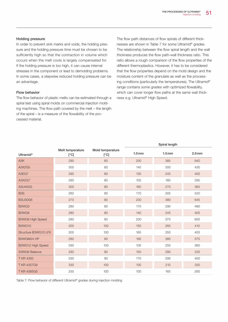
51
Holding pressure
In order to prevent sink marks and voids, the holding pres-sure and the holding pressure time must be chosen to be sufficiently high so that the contraction in volume which occurs when the melt cools is largely compensated for. If the holding pressure is too high, it can cause internal stresses in the component or lead to demolding problems. In some cases, a stepwise reduced holding pressure can be an advantage.
Flow behavior
The flow behavior of plastic melts can be estimated through a spiral test using spiral molds on commercial injection mold-ing machines. The flow path covered by the melt – the length of the spiral – is a measure of the flowability of the pro-cessed material.
The flow path distances of flow spirals of different thick-nesses are shown in Table 7 for some Ultramid® grades. The relationship between the flow spiral length and the wall thickness produces the flow path-wall thickness ratio. This ratio allows a rough comparison of the flow properties of the different thermoplastics. However, it has to be considered that the flow properties depend on the mold design and the moisture content of the granulate as well as the process-ing conditions (particularly the temperatures). The Ultramid® range contains some grades with optimized flowability, which can cover longer flow paths at the same wall thick-ness e.g. Ultramid® High Speed.
Table 7: Flow behavior of different Ultramid® grades during injection molding
Spiral length
Ultramid® Melt temperature
[°C]Mold temperature
[°C] 1.0 mm 1.5 mm 2.0 mm
A3K 290 60 200 385 640
A3X2G5 300 80 145 300 430
A3EG7 290 80 130 245 400
A3X2G7 290 80 105 180 295
A3U40G5 300 80 160 270 365
B3S 260 80 170 305 520
B3U30G6 270 80 230 380 645
B3WG3 280 80 170 290 490
B3WG6 280 80 140 245 405
B3WG6 High Speed 280 80 200 375 605
B3WG10 300 100 150 265 410
Structure B3WG10 LFX 300 100 165 350 455
B3WGM24 HP 280 80 195 385 575
B3WG12 High Speed 290 100 105 250 360
S3WG6 Balance 290 80 150 280 335
T KR 4350 330 90 170 295 400
T KR 4357G6 330 100 130 210 330
T KR 4365G5 330 100 100 165 265
THE PROCESSING OF ULTRAMID® Injection molding

52
Shrinkage and aftershrinkage
ISO 294-4 defines the terms and test methods for shrinkage in processing. According to this, shrinkage is defined as the difference in the dimensions of the mold and those of the injection-molded part at room temperature. It results from the volumetric contraction of the melt in the injection mold due to cooling, change in the state of aggregation and crys-tallization.
Shrinkage is also affected by the geometry (free or imped-ed shrinkage) and the wall thickness of the molded part (Fig. 35). In addition, the position and size of the gate and the processing parameters (melt and mold temperature, holding pressure and holding pressure time together with the storage time and storage temperature) play an important role. The interaction of these various factors makes it dif-ficult to predict the shrinkage of a part exactly.
Molding shrinkage [%]
Ultramid® Melt temperature
[°C]Mold temperature
[°C]Testbox1) Sheet2)
crosswise lengthwise
A3K, A3W 290 60 0.85 1.40 1.70
A3HG5, A3EG5, A3WG5 290 80 0.55 0.50 1.10
A3X2G5 290 80 0.50 0.50 1.25
A3EG6, A3WG6 290 80 0.55 0.40 1.05
A3X2G7 290 80 0.45 0.35 1.15
A3EG10, A3WG10 300 80 0.45 0.35 0.80
A3U42G5 290 80 0.50 0.40 1.10
B3S 260 60 0.55 0.90 1.00
B3ZG3 280 80 0.50 0.60 0.70
B3ZG6 280 80 0.40 0.30 0.70
B3EG6, B3WG6 280 80 0.40 0.25 0.75
B3WG7 280 80 0.35 0.25 0.75
B3WG10 300 80 0.30 0.20 0.70
Structure B3WG10 LFX 305 80 0.30 0.50
B3WGM24 HP 280 80 0.40 0.40 0.60
B3U30G6 270 80 0,50 0.40 0.90
B3K6 270 80 0.75 1.05 1.05
B3GK24 280 80 0.50 0.50 0.80
B3M6 270 80 0.75 0.95 1.05
B3WGM35 280 80 0.35 0.35 0.80
C3U 270 60 0.80 1.25 1.30
S3WG6 Balance 270 80 0.40 0.40 0.90
T KR 4350 315 90 0.60 0.90 1.10
T KR 4357 G6 320 100 0.35 0.40 1.00
T KR 4365 G5 320 100 0.40 0.30 0.80
Table 8: Shrinkage behavior of different Ultramid® grades1) Impeded shrinkage, see Fig. 36, x axis, line A, wall thickness 1.5 mm, holding pressure 800 bar 2) Free shrinkage according to ISO 294-4, sheet 60 x 60 x 2 mm, internal mold pressure 500 bar
THE PROCESSING OF ULTRAMID® Injection molding

53
Fig. 35: Impeded shrinkage of Ultramid® as a function of wall thickness, test box, line A, holding pressure: 600 bar
Shr
inka
ge [%
]
Thickness [mm]
1 2 3 4 50
0.5
1
1.5
2
Fig. 37: Test box
C
B
A
D
E
A ≈ 107 mm B ≈ 47 mm C ≈ 40 mm D ≈ 60 mm E ≈ 120 mm
The shrinkage values measured on plates 60 mm x 60 mm x 2 mm according to ISO 294 can be used to compare the shrinkage of different materials. The plaques injected with a film gate have the minimum and maximum shrinkage parallel and perpendicular to the flow direc-tion because of the high orientation of the molecules and, particularly, the fibers. The value measured on the test box (Fig. 37) can be used as a guide for the average shrinkage in a real part since, here, the flow front tends to run radially from the injection point. Table 8 gives an over-view of the shrinkage values of various Ultramid® grades.
Unreinforced polyamides generally shrink more than rein-forced grades. Some processing conditions have a significant effect on dimensional stability, particularly in unreinforced products. These include the mold temperature, holding pres-sure and time. Nevertheless, the possible holding pressure range of a real part is usually limited, as a too low holding pressure can lead to sink marks and a too low holding pres-sure to demolding problems. However, the melt temperature generally has relatively little effect. The factors that may affect reinforced Ultramid® are limited by the processing param-eters. Figures 36, 38 and 39 show shrinkage values of rein-forced and unreinforced Ultramid® as a function of holding pressure, melt and mold temperature.
0.2
0.5
0.3
0.4
0.6
0.7
0.8
0.9
1.0
1.1
1.3
1.2
Fig. 36: Shrinkage of Ultramid® A, B and T as a function of holding pressure, test box, line A, thickness: 1,5 mm
Holding pressure [bar] 300 400 500 600 700 800 900 1000 1100 1200 1300
A3K, Tmelt 290 °C / Tmold 60 °C A3X2G5, Tmelt 290 °C / Tmold 80 °C A3EG6, Tmelt 290 °C / Tmold 80 °C B3EG6, Tmelt 290 °C / Tmold 80 °C T KR 4350, Tmelt 320 °C / Tmold 80 °C
Shr
inka
ge [%
]
THE PROCESSING OF ULTRAMID® Injection molding
A3K B3EG6 B3EG3 B3WGM24 A3EG6

54
Post-shrinkage means that the dimensions of the moldings may change slightly over time because internal stresses and orientations are dissipating and post-crystallization can take place depending on time and temperature. Whereas the post-crystallization is comparatively low at room temper-ature, at higher temperatures it can result in a possibly sig-nificant dimensional change. The process of post-shrinkage can be accelerated by annealing. High mold temperatures reduce the level of post-shrinkage and can therefore replace an additional annealing process (Fig. 39).
Fig. 39: Shrinkage after storage in standard climate (23 °C, 50 % r.h.) and after heat-aging 20 h at 160 °C of Ultramid® A and B as a function of the mold temperature, test box, thickness: 1.5 mm
Mold temperature [°C]
11030 40 50 60 70 80 90 1000.0
0.6
0.2
0.4
0.8
1.0
1.2
1.4
1.6
1.8
2.0
A3K A3WG6 B3WG6
Shrinkage after storage 16-24 h at 23 °C 50 % r.h.
Shrinkage after heat-aging 20 h 160 °C
Shr
inka
ge [%
]
THE PROCESSING OF ULTRAMID® Injection molding
Fig. 38: Shrinkage of Ultramid® A and B as a function ofmelt temperature (test box, thickness: 1.5 mm)
Melt temperature [°C]260 270 280 290 300 310 320 330
0.2
0.5
0.3
0.4
0.6
0.7
0.8
0.9
1.0
1.1 A3K, Tmold 60 °C B3M6, Tmold 80 °C A3X2G5, Tmold 80 °C A3EG6, Tmold 80 °C B3EG6, Tmold 80 °C
Shr
inka
ge [%
]
Moldings of glass-fiber reinforced products show a signifi-cant difference in the shrinkage perpendicular and parallel to the flow direction (shrinkage anisotropy). This is the result of the typical orientation of the glass fibers longitudinally to the flow direction (Fig. 40).

55
Fig. 40: Impeded shrinkage of different Ultramid® grades as a function of wall thickness, sheet measuring 110 x 110 mm with a film gate and injection molded corners to impede deformation, holding pressure = 500 bar; perpendicular ( ) and parallel (II) to the flow direction
Shr
inka
ge [%
]
Wall thickness [mm]
0,5 4,53,52,51,50
0,5
1
1,5
Warpage
Warpage in a molding is mainly caused by different shrinkag-es in flow direction and perpendicular. That is why parts made of glass-fiber reinforced materials tend more to warp than those made of unreinforced products. In addition, it depends on the shape of the moldings, the distribution of wall thicknesses and on the processing conditions.
In the case of unreinforced grades, different temperature control of individual parts of the mold (core and cavity) can allow the production of warp-free or low-warpage molded parts. Thus, for example the warpage of housing parts to the inner side can be counteracted by low core and high cavity temperatures.
Mineral and glass bead-filled grades are characterized by largely isotropic shrinkage. They are therefore the preferred materials for molded parts with low warpage.
Special processes
Multi-component technology
The combination of several materials in one molding has become firmly established in injection molding technology. Various Ultramid® grades are used here, depending on what component properties are required. The components must be matched to one another in respect of their processing and material properties. A lot of experience exists in rela-tion to the way that different materials adhere to Ultramid®. Information can be obtained from the technical information “Rigid-flexible joints in injection molding technology”.
Injection molding with fluid injection technology (FIT)
Fluid injection technology offers opportunities that are inter-esting from a technological and economic point of view for producing complex, (partially) thick-walled molded parts with hollows and functions that can be integrated. Typical FIT components made of Ultramid® are media lines in auto-mobiles, handles, brackets and chairs.
After the melt has been injected, a fluid is used to eliminate any residual molten material. Depending on the application, the fluid used can be gas or water. With projectile injection technology, a fluid-driven projectile is used.
The fluid pressure applied internally can reduce the warp-age of the component. Shorter cycle times can also be achieved because more heat is dissipated with water and the accumulation of melt is avoided. Other advantages are greater freedom of design and the opportunity to create components with high specific rigidity.
At present, the products used are primarily reinforced Ultramid® grades. Some Ultramid® grades are optimized for FIT; for example the hydrolysis-resistant Ultramid® A3HG6 WIT is particularly suitable for cooling water pipes, while other grades, e. g. Ultramid® B3WG6 GIT, allow particularly good surface qualities.
THE PROCESSING OF ULTRAMID®
Special processes
A3K A3K II A3EG6 A3EG6 II
B3EG3 B3EG3 II B3EG6 B3EG6 II
Coolant water pipe

56
Overmolding of inserts
Well known applications in which metal inserts are over-molded with Ultramid® include connecting elements such as shells or inserts and conductor paths or similar elements in control housings. These molded parts require a particularly good joint between the metal and plastic if they need to be resistant to media or are exposed to varying temperatures. The metal inserts should be pre-heated to 100 °C to 150 °C, but at least to mold temperature, before overmolding to pre-vent excessive internal stresses in the molded part. The metal parts must be grease-free and, where necessary, should have knurls, surrounding notches or similar elements for more fixing. Other metal pre-treatments such as structur-ing of the contact area, plasma nitriding or special coatings can also improve adhesion.
Chemical and physical foaming
The addition of chemical or physical blowing agents causes the melt to expand during the filling of the mold. Sink marks can be avoided even with large wall thicknesses. If necessary, it also allows the weight of the component to be reduced. In addition, the fill pressure is considerably reduced so that a machine with a lower clamping force can be used. Foamed components have lower warpage than compact injection molded components. However, it should be considered that the mechanical and the surface properties can be influenced in a negative way depending on the level of expansion. With selected Ultramid® grades from the range, good surfaces can be achieved, even with foam injection molding.
An experienced team of experts is available to answer ques-tions about processing, processing methods and special processing methods. A well-equipped processing technolo-gy center can be used for research, development and proj-ect studies. The back injection molding of thermoplastic composites, multi-component injection molding, GID / WIT technology and processing of high-temperature thermoplas-tics are some of the special processes that are possible in our technical lab.
THE PROCESSING OF ULTRAMID®
Special processes
Rear axle transmission cross beam

57
Joining methods
Parts made of Ultramid® can be joined by a variety of differ-ent methods. These include the following in particular: Snapping together Screwing together with self-tapping metal screws Screwing together with threaded inserts Riveting Adhesive bonding Welding
Snap fittings can easily be integrated into Ultramid® plastic parts. Good flexibility over a large temperature range is par-ticularly advantageous for this joining method.
Direct screw fixings and screw fixings with threaded inserts allow strong bonds to be formed between two Ultramid® parts and between Ultramid® parts and parts made of other materials.
Riveted joints are generally produced with integrated rivets. These can be softened by ultrasound, a hot riveting die, hot gas or a laser. A form closure is created by the subsequent molding of the rivet head.
All common adhesive systems are suitable for bonding Ultramid®. The complexity of the bonding process requires particular care to be taken when choosing the adhesive and pre-treating the parts.
Virtually all common methods can be used to weld Ultramid®: Friction welding (vibration and spin welding) Ultrasonic welding Laser beam welding Infrared welding Hot gas welding Heat impulse welding High frequency welding
These welding methods have their own specific advantages and disadvantages and require certain material properties. As the optimum weld geometry depends on the welding method used, the method should be chosen before the final design is drawn up.
With UltrajoinTM and UltratestTM BASF offers its customers extensive support: from the choice of the most suitable bonding technique to the design of the joint to the optimiza-tion of the joining process.
Machining
Semi-finished products made from Ultramid® can be pro-cessed with all commonly known tooling machines. As a general rule of guidance, one might use an adjusted feed rate and a high cutting speed. Additionally, tools should be checked for sufficient sharpness.
THE PROCESSING OF ULTRAMID®
Joining methods

58
Marking and coating
Laser marking
Marking Ultramid® using lasers affords a series of advantag-es over conventional methods, particularly when there are tough requirements for permanence, flexibility and speed.
The following information is intended only to provide initial guidance. The Ultra-Infopoint will be happy to give more detailed advice on the choice of Ultramid® colors that are best suited to laser marking.
Nd-YAG lasers (wavelength 1064 nm)Uncolored standard Ultramid® grades are practically impossible to mark with Nd-YAG lasers due to very low absorption of energy. This also applies to glass-fiber reinforced and min-eral-filled grades. Better markability for Ultramid® grades can be achieved by using special additives. High-contrast lettering is obtained with certain black pigmentations.
Uncolored Ultramid® A3X grades can be marked with good contrast but not in customary black colors.
The Ultramid® LS range comprising unreinforced, reinforced and flameproofed grades was specially developed for mark-ing using the Nd-YAG laser. The Ultra-Infopoint will be happy to send you an overview on request.
Nd-YAG lasers (wavelength 532 nm) A frequency-doubled Nd-YAG laser can generally produce higher definition and higher contrast images on uncolored and brightly colored Ultramid® grades than a Nd-YAG laser with 1064 nm. There is no advantage in the case of black colors.
Excimer lasers (wavelength 175-483 nm)Excimer lasers produce a higher definition and a better surface finish on Ultramid® than do Nd-YAG devices. Good results are achieved especially for bright colors.
CO2 lasers (wavelength 10640 nm) Uncolored and colored Ultramid® is practically impossible to mark with CO2 lasers. At best there is only barely perceptible engraving of the surface without color change.
Laser marked test specimen
THE PROCESSING OF ULTRAMID®
Marking and coating

59
Printing
Printing on Ultramid® using conventional paper-printing methods requires no pretreatment. Injection-molded parts should be largely free of internal stresses and produced as far as possible without mold release agents, particularly those containing silicone. Special tried and tested inks are available for printing to Ultramid®.
Hot embossing
Ultramid® can be hot-embossed easily with suitable embossing foils.
Surface coating
Due to its outstanding resistance to most solvents, Ultramid® can be coated in one or more layers with various paints, which adhere well and have no adverse effects on mechani-cal properties. One- or two-component paints with binders matched to the substrate are suitable. Waterborne paints and primers can also be applied to Ultramid®. A mixture of isopropanol and water or other specific cleaning agents can be used for preliminary treatment. Industrial processes, such as preliminary treatment in automotive paint shops, are also suitable for cleaning. Coating based on electrostatics is only possible with what is known as a conductive primer as Ultramid® is not sufficiently conductive in its own right.
Metallizing
After proper pre-treatment, parts made of Ultramid® can be metallized galvanically or in a high vacuum. A flawless surface is achievable with both unreinforced as well as rein-forced grades. Metallized parts made of Ultramid® are increasingly used in the sanitary, the electronics and auto-motive industries.
THE PROCESSING OF ULTRAMID®
Marking and coating
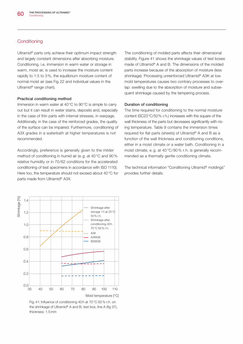
60
Conditioning
Ultramid® parts only achieve their optimum impact strength and largely constant dimensions after absorbing moisture. Conditioning, i.e. immersion in warm water or storage in warm, moist air, is used to increase the moisture content rapidly to 1.5 to 3 %, the equilibrium moisture content of normal moist air (see Fig. 22 and individual values in the Ultramid® range chart).
Practical conditioning method
Immersion in warm water at 40 °C to 90 °C is simple to carry out but it can result in water stains, deposits and, especially in the case of thin parts with internal stresses, in warpage. Additionally, in the case of the reinforced grades, the quality of the surface can be impaired. Furthermore, conditioning of A3X grades in a waterbath at higher temperatures is not recommended.
Accordingly, preference is generally given to the milder method of conditioning in humid air (e. g. at 40 °C and 90 % relative humidity or in 70 / 62 conditions for the accelerated conditioning of test specimens in accordance with ISO 1110). Here too, the temperature should not exceed about 40 °C for parts made from Ultramid® A3X.
The conditioning of molded parts affects their dimensional stability. Figure 41 shows the shrinkage values of test boxes made of Ultramid® A and B. The dimensions of the molded parts increase because of the absorption of moisture (less shrinkage). Processing unreinforced Ultramid® A3K at low mold temperatures causes two contrary processes to over-lap: swelling due to the absorption of moisture and subse-quent shrinkage caused by the tempering process.
Duration of conditioning
The time required for conditioning to the normal moisture content (SC23 °C / 50 % r. h.) increases with the square of the wall thickness of the parts but decreases significantly with ris-ing temperature. Table 9 contains the immersion times required for flat parts (sheets) of Ultramid® A and B as a function of the wall thickness and conditioning conditions, either in a moist climate or a water bath. Conditioning in a moist climate, e. g. at 40 °C / 90 % r. h. is generally recom-mended as a thermally gentle conditioning climate.
The technical information “Conditioning Ultramid® moldings” provides further details.
Fig. 41: Influence of conditioning 40 h at 70 °C 62 % r.h. on the shrinkage of Ultramid® A and B, test box, line A (fig 37), thickness: 1.5 mm
Mold temperature [°C]
11030 40 50 60 70 80 90 1000.0
1.0
0.6
0.4
0.2
0.8
1.2
1.4
A3K A3WG6 B3WG6
Shrinkage after storage 1 h at 23 °C 50 % r.h.
Shrinkage after conditioning 40 h 70 °C 62 % r.h.
Shr
inka
ge [%
]
THE PROCESSING OF ULTRAMID®
Conditioning
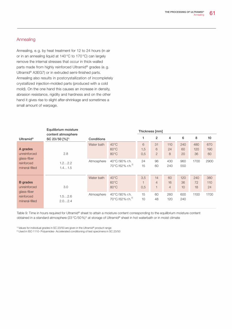
61
Ultramid®
Equilibrium moisturecontent atmosphereSC 23 / 50 [%]1) Conditions
Thickness [mm]
1 2 4 6 8 10
A gradesunreinforcedglass-fiberreinforcedmineral-filled
2.8
1.2…2.21.4…1.5
Water bath 40 °C 60 °C 80 °C
6 1,5 0,5
31 6 2
110 24 8
240 60 20
480 120 36
670 190 60
Atmosphere 40 °C / 90 % r.h. 70 °C / 62 % r.h.2)
24 15
96 60
430 240
960 550
1700 2900
B gradesunreinforcedglass-fiberreinforcedmineral-filled
3.0
1.5…2.6 2.0…2.4
Water bath 40 °C 60 °C 80 °C
3,5 1
0,5
14 4 1
60 16 4
120 36 10
240 72 18
380 110 24
Atmosphere 40 °C / 90 % r.h. 70 °C / 62 % r.h.2)
15 10
60 48
260 120
600 240
1100 1700
Table 9: Time in hours required for Ultramid® sheet to attain a moisture content corresponding to the equilibrium moisture contentobtained in a standard atmosphere (23 °C / 50 %)1) at storage of Ultramid® sheet in hot waterbath or in moist climate
1) Values for individual grades in SC 23/50 are given in the Ultramid® product range2) Used in ISO 1110- Polyamides- Accelerated conditioning of test specimens in SC 23/50
Annealing
Annealing, e. g. by heat treatment for 12 to 24 hours (in air or in an annealing liquid at 140 °C to 170 °C) can largely remove the internal stresses that occur in thick-walled parts made from highly reinforced Ultramid® grades (e. g. Ultramid® A3EG7) or in extruded semi-finished parts. Annealing also results in postcrystallization of incompletely crystallized injection-molded parts (produced with a cold mold). On the one hand this causes an increase in density, abrasion resistance, rigidity and hardness and on the other hand it gives rise to slight after-shrinkage and sometimes a small amount of warpage.
THE PROCESSING OF ULTRAMID®
Annealing
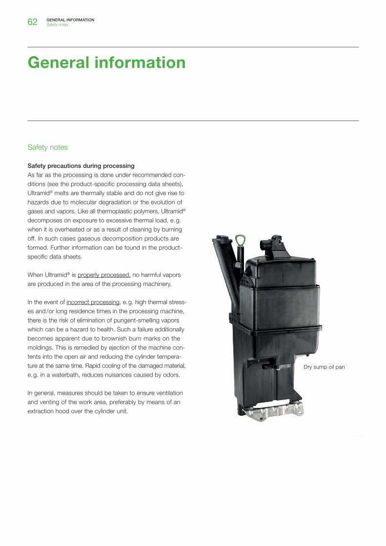
62
Safety notes
Safety precautions during processing
As far as the processing is done under recommended con-ditions (see the product-specific processing data sheets), Ultramid® melts are thermally stable and do not give rise to hazards due to molecular degradation or the evolution of gases and vapors. Like all thermoplastic polymers, Ultramid® decomposes on exposure to excessive thermal load, e. g. when it is overheated or as a result of cleaning by burning off. In such cases gaseous decomposition products are formed. Further information can be found in the product-specific data sheets.
When Ultramid® is properly processed, no harmful vapors are produced in the area of the processing machinery.
In the event of incorrect processing, e. g. high thermal stress-es and / or long residence times in the processing machine, there is the risk of elimination of pungent-smelling vapors which can be a hazard to health. Such a failure additionally becomes apparent due to brownish burn marks on the moldings. This is remedied by ejection of the machine con-tents into the open air and reducing the cylinder tempera-ture at the same time. Rapid cooling of the damaged material, e. g. in a waterbath, reduces nuisances caused by odors.
In general, measures should be taken to ensure ventilation and venting of the work area, preferably by means of an extraction hood over the cylinder unit.
GENERAL INFORMATIONSafety notes
General information
Dry sump oil pan

63
Design cutlery
GENERAL INFORMATIONSafety notes
Food regulations
The grades in the Ultramid® range marked FC comply with the current legislation on plastics in contact with food in Europe and the USA. In addition, the conformity of these products is guaranteed by manufacturing in accordance with the GMP (Good Manufacturing Practice) Food Contact stan-dard. If detailed information about the food approval status of a particular Ultramid® grade is required, please contact BASF directly ([email protected]). BASF will be happy to provide an up-to-date declaration of conformity based on the current legal regulations.
Available under the name FC Aqua® are Ultramid® grades which, in addition to being used in components in contact with food, also have different country-specific approvals for applications involving contact with drinking water. All plastics in the Aqua® range have the approvals in line with KTW1), DVGW 2), and WRAS 3) in cold-water applications, and a large proportion of them for warm and hot water, too. In order to make it easier for the finished components to be approved, BASF provides all the certifiates required for Germany and Great Britain. If approvals from the ACS4), the 5NSF5) or other institutes are required, BASF assists by dis-closing the formulation to the institutes. For questions regarding compliance with further regulations and certifi-cates, please contact your local BASF representative or Plastics Safety (e-mail: [email protected]).
1) KTW: Kontakt mit Trinkwasser (Germany)2) DVGW: Deutscher Verein des Gas- und Wasserfachs (Germany)3) WRAS: Water Regulation Advisory Scheme (UK)4) ACS: Attestation de Conformite Sanitaire (France)5) NSF: National Sanitation Foundation (USA)

64 GENERAL INFORMATIONSustainability
Sustainability
Responsible management of resources at BASF
BASF works with customers to provide sustainable prod-ucts and solutions, which help it to achieve its sustainability targets and market differentiation. Technical plastics such as Ultramid® can be produced efficiently and save resources during the lifetime of the components. BASF has also set itself the objective of closing material cycles and making the best possible use of resources along the value chain. BASF is focusing on two approaches: biomass balance and ChemCycling.
In the biomass balance approach, some fossil raw materials are replaced by renewable raw materials in the first stage of the production process and then allocated to the cor-responding product. These certified materials are obtained from various value chains, preferably from organic waste or byproducts. The method promotes the use of renewable raw materials, saves fossil resources and reduces green-house gas emissions. In the group as a whole, more than 20,000 customer products can be produced using the bio-mass balance approach.
In the ChemCycling project, BASF is following a new approach to recycling plastic waste. Partner companies use thermo-chemical processes to convert the waste into raw materials (e. g. pyrolysis oils) which are fed into the BASF group’s production stream.
New chemical products are therefore created on the basis of recycled plastic waste, which are given the suffix ‘Ccy-cled’. Chemical recycling can help to reduce the amount of plastic waste sent to landfill sites or for thermal recycling. With chemical recycling we are helping our customers to produce products from recycled materials.
Both approaches have these advantages in common:
Some fossil raw materials are replaced with renewable raw materials, obtained from biomass or raw materials pro-duced from recycled plastic waste.
The raw materials can be used in all BASF materials pro-duced by the group. They can be used universally in end user products.
The end product retains the same chemical composition and quality.
The use of biomass and raw materials recovered from plastic waste saves CO2.
The mass balance process ensures that the renewable or recycled raw material is allocated correctly to the relevant BASF product.
The ChemCycling or biomass balance products are certified by independent external institutions in accordance with the relevant standards.
BASF is working with customers to develop solutions for their sustainability requirements on the basis of these approaches.
Waste companies supplyrecyclers with plastic waste1
Plastic waste is convertedinto feedstock2
This feedstock can be used tocreate all kinds of chemicalsand products, especially plastics
3
Customers use these tomake their own products 4
Consumers and companiesuse and dispose of products 5
The waste is collected andsorted by waste companies 6
Fig. 42: ChemCycling: from plastic waste to new products
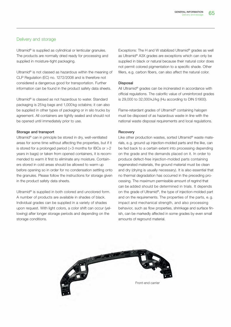
65GENERAL INFORMATIONDelivery and storage
Delivery and storage
Ultramid® is supplied as cylindrical or lenticular granules. The products are normally dried ready for processing and supplied in moisture-tight packaging.
Ultramid® is not classed as hazardous within the meaning of CLP Regulation (EC) no. 1272/2008 and is therefore not considered a dangerous good for transportation. Further information can be found in the product safety data sheets.
Ultramid® is classed as not hazardous to water. Standard packaging is 25 kg bags and 1,000 kg octabins; it can also be supplied in other types of packaging or in silo trucks by agreement. All containers are tightly sealed and should not be opened until immediately prior to use.
Storage and transport
Ultramid® can in principle be stored in dry, well-ventilated areas for some time without affecting the properties, but if it is stored for a prolonged period ( > 3 months for IBCs or > 2 years in bags) or taken from opened containers, it is recom-mended to warm it first to eliminate any moisture. Contain-ers stored in cold areas should be allowed to warm up before opening so in order for no condensation settling onto the granules. Please follow the instructions for storage given in the product safety data sheets.
Ultramid® is supplied in both colored and uncolored form. A number of products are available in shades of black. Individual grades can be supplied in a variety of shades upon request. With light colors, a color shift can occur (yel-lowing) after longer storage periods and depending on the storage conditions.
Exceptions: The H and W stabilized Ultramid® grades as well as Ultramid® A3X grades are exceptions which can only be supplied in black or natural because their natural color does not permit colored pigmentation to a specific shade. Other fillers, e.g. carbon fibers, can also affect the natural color.
Disposal
All Ultramid® grades can be incinerated in accordance with official regulations. The calorific value of unreinforced grades is 29,000 to 32,000 kJ/kg (Hu according to DIN 51900).
Flame-retardant grades of Ultramid® containing halogen must be disposed of as hazardous waste in line with the national waste disposal requirements and local regulations.
Recovery
Like other production wastes, sorted Ultramid® waste mate-rials, e. g. ground up injection-molded parts and the like, can be fed back to a certain extent into processing depending on the grade and the demands placed on it. In order to produce defect-free injection-molded parts containing regenerated materials, the ground material must be clean and dry (drying is usually necessary). It is also essential that no thermal degradation has occurred in the preceding pro-cessing. The maximum permissible amount of regrind that can be added should be determined in trials. It depends on the grade of Ultramid®, the type of injection-molded part and on the requirements. The properties of the parts, e. g. impact and mechanical strength, and also processing behavior, such as flow properties, shrinkage and surface fin-ish, can be markedly affected in some grades by even small amounts of reground material.
Front-end carrier

66 GENERAL INFORMATIONIntegrated management system
Integrated management system
QHSE management
Quality, health, safety and environmental management are key elements of BASF’s corporate policy. Our primary aim is to become even better at identifying and fulfilling our cus-tomers’ needs. The continuous improvement of our prod-ucts and services in terms of quality, safety, environment and health is a fundamental element of this.
BASF’s Performance Materials Europe business unit uses an integrated management system for the Ultramid® prod-ucts certified according to the following standards
The business unit is recognized by an accredited certification company for its: ISO 9001 (Quality management system) IATF 16949 (Automobile industry quality management standard)
ISO 14001 (Environment management system) and ISO 50001 (Energy management system) or EMAS.
Seat structure
Door handle

67GENERAL INFORMATIONServices
Services
BASF is more than a manufacturer of raw materials, able to deliver innovative plastics on time and to the required quality. We support and advise our customers on sustain-able developments in many different application areas with application-specific know-how, technical service and simula-tions. We also have well equipped technical departments which specialize in processing technologies, material and component testing.
Ultrasim®
Ultrasim® is BASF’s comprehensive and flexible CAE expertise with innovative BASF plastics. The modern calcu-lation of thermoplastic components is very demanding for the developer. When it comes to the interaction between manufacturing process, component geometry and material, only an integrated approach can lead to an ideal compo-nent. Plastics reinforced with short glass fibers in particular have anisotropic properties depending on how the fibers perform in injection molding. Modern optimization methods support the component design and can improve it in every phase of its development.
BASF’s integrative simulation incorporates the manufac-turing process of the plastic component into the calcula-tion of its mechanical performance. This is provided by a completely new numerical description of the material which takes the properties typical of the plastic into account in the mechanical analysis. These properties include
Anisotropy Non-linearity Dependence on strain rate Tension-compression asymmetry Failure performance Dependence on temperature.
The new Ultrasim® thermomechanics module can also be used to simulate temperature-dependent deformations under any temperature load and distribution. A separate module for simulating thermally conductive plastics com-pletes the Ultrasim® modeling portfolio.
As seen, BASF is more than a raw material manufacturer supplying innovative plastics that meet delivery time and quality requirements. Ultrasim® adapts flexibly to meet indi-vidual customer requirements – for highly loadable effi-cient, lightweight parts and thus longterm market success.
UltratestTM und UltrajoinTM
UltratestTM represents the many different competences and activities which support our customers with component analysis and optimization through experimental methods.
UltrajoinTM contains our comprehensive know-how and our unique infrastructure for bonding techniques.
Support, which is available worldwide, makes an important contribution in all phases of development – from the materi-al, and application development through simulation to com-ponent analysis for series production.
If necessary, the extensive equipment can be adapted or new test set-ups can be developed to ensure that tests meet the customer-specific requirements. Live transmissions allow our customers to take part in the tests without having to be in the BASF laboratory.
The test options include e. g.: Temperature, temperature shock and climate tests, including in an inert atmosphere
Chemical stability tests Quasi-static, dynamic and impact tests with external forces or internal pressures
Vibration analyses, acoustic analyses Flow and leak tests Non-destructive testing with computer tomography Digital geometry, deformation and strain measurements Temperature field analyses with IR thermography Documentation of all transient processes with high-speed cameras
Testing, evaluation and optimization of all relevant joining methods (see also Joining methods chapter)
Laser transparency and laser markability analyses
Torque rod support

68 GENERAL INFORMATIONNomenclature
Subnames
Subnames are optionally used in order to particularly emphasize a product feature that is characteristic of part of a range.
Examples of subnames:Endure Particularly good long-term stabilization
against hot airStructure Particularly good notched impact strength at
low temperatures, and without any disadvan-tages for the stiffness and strength
Vision Significantly increased translucence in the visible range
Advanced Polyphthalamide Deep Gloss High-gloss with increased abrasion
resistance and UV stability
Technical ID
The technical ID is made up of a series of letters and num-bers which give hints about the polymer type, the melt vis-cosity, the stabilization, modification or special additives and the content of reinforcing agents, fillers or modifiers. The fol-lowing classification scheme is found with most products:
Ultramid® Subname Technical ID Suffixes Color
Letters for identifying polymer types
A Polyamide 66B Polyamide 6C Copolyamide 66/6D Special polymerN Polyamide 9TS Polyamide 610T Copolyamide with 6T
Numbers for identifying viscosity classes
3 Free-flowing, low melt viscosity, mainly for injection molding
35 Low to medium viscosity4 Medium viscosity
Letters for identifying stabilization
E, K Stabilized, light natural color, increased heat-aging, weather and hot water resistance, electrical proper-ties are not impaired
H Stabilized, increased heat-aging, hot water and weather resistance only for engineering parts, electri-cal properties remain unaffected, depending on the grade light-beige to brown natural color
W Stabilized, high resistance to heat-aging, can only be supplied uncolored and in black, less suitable if high demands are made on the electrical properties of the parts
Nomenclature
Structure
The name of Ultramid® commercial products generally follows the scheme below:
Ultramid® T generally has the following classification scheme:
B 3 E 2 G 6
Polymer type
Viscosity class
Type of reinforcing agent / filler
Content of reinforcing agent /filler or modifier
Type of stabilization or modification, special additives
Generation number (optional)
T KR 4 3 . . G 6
Polymer type
Type of reinforcing agent / filler
Content of reinforcing agent / filler or modifier

69GENERAL INFORMATIONNomenclature
Letters for identifying special additives
F Functional additiveL Impact-modified and stabilized, impact resistant
when dry, easy flowing, for rapid processingS For rapid processing, very fine crystalline structure,
for injection moldingU With flame-retardant finish without red phosphorusX With red phosphorus as the flame-retardant finishZ Impact-modified and stabilized with very high low-
temperature impact strength (unreinforced grades) or enhanced impact strength (reinforced grades)
Letters for identifying reinforcing agents / fillers
C Carbon fibersG Glass fibersK Glass beadsM MineralsGM Glass fibers in combination with mineralsGK Glass fibers in combination with glass beads
Key numbers for describing the content of
reinforcing agents / fillers or modifiers
2 approx. 10 % by mass3 approx. 15 % by mass4 approx. 20 % by mass5 approx. 25 % by mass6 approx. 30 % by mass7 approx. 35 % by mass8 approx. 40 % by mass10 approx. 50 % by mass
In the case of combinations of glass fibers with minerals or glass beads, the respective contents are indicated by two numbers, e. g.
GM53 approx. 25 % by mass of glass fibers and approx. 15 % by mass of minerals
GK24 approx. 10 % by mass of glass fibers and approx. 20 % by mass of glass beads
M602 represents approx. 30 % by mass of a special silicate (increased stiffness).
Suffixes
Suffixes are optionally used in order to indicate specific pro-cessing or application-related properties. They are frequently acronyms whose letters are derived from the English term.
Examples of suffixes:Aqua® Meets specific regulatory requirements for drinking water applicationsBalance Based at least partly on renewable raw materialsBM Blow molding gradeCR Crash ResistantEQ Electronic QualityFC Food Contact; meets specific regulatory re-
quirements for applications in contact with food GIT Gas Injection TechnologyGP General PurposeGPX New Generation “General Purpose”High Speed High flowability of the meltHP High ProductivityHR Hydrolysis Resistant, increased hydrolysis
resistanceHRX New generation of HR productsLDS Laser Direct Structuring, for preparing the
electroplating of electrical conductor tracksLF Long Fiber ReinforcedLS Laser Sensitive, can be marked with
Nd:YAG laserLT Laser Transparent, can be penetrated well with
Nd:YAG lasers and lasers of a similar wave-length
SF Structural FoamingSI Surface Improved, for parts with improved
surface qualityST Super ToughWIT Water Injection Technology
Color
The color is generally made up of a color name and a color number.
Examples of color names:UncoloredBlack 00464Black 00564Black 20560

70 GENERAL INFORMATIONSubject index
Subject index
Advantages Aftershrinkage 52 ff.Annealing 61Automotive engineering 4 f.
Behavior on– exposure to weather 42 ff.– heat 28Behavior under – cyclic loads, flexural fatigue strength 27– long-term static loading 26
Chassis and engine mounting 4ChemCycling 64Chemical and physical foaming 56CO2 lasers 58Component testing 67Compound temperatures 49Cooling system 4Conditioning 60Construction industry 35Consumer goods 8 f.
Delivery 65Dimensional stability 30 f. Disposal 65 Domestic appliances 6Drying 45Duration of conditioning 60
Electrical engineering 34Electrical properties 32 f.Electrical systems 4Electrical and electronics sector 6 f.Electronics 6Embossing 59Engine and transmission 4Environment 66Environmental management 66Excimer lasers 58Exterior 4
Fire behavior 34 f.Flow behavior 51Fluid injection technology (FIT) 55Food regulations 63Fuel system 4Glass-fiber reinforced Ultramid® 11
Heat-aging resistance 29Heat-aging resistance in– coolants 30 – hot lubricants 30– solvents 30Holding pressure 51Hot embossing 59Household 8
Impact strength 25 f.Injection mold 47 f. Injection molding 49 ff.Industrial products 8 f.Injection rate 50 Interior 4
Joining methods 57
Laser marking 58Low-temperature impact strength 25 f.
Machine and mold technique for injection molding 46 ff. Machining 57Management system 66Materials handling 8Mechanical and apparatus engineering 8Mechanical properties 22 ff.Melt viscosity 44Melting behavior 43Metallizing 59Mineral-filled Ultramid® 11Mold technique for injection molding 46 ff.Multi-component technology 55
71GENERAL INFORMATIONSubject index
Nd-YAG lasers 58Nomenclature 68 f.
Overmolding of Inserts 56
Photovoltaics 6Plasticizing unit 46 f.Power technology 6Practical conditioning method 60Preliminary treatment 45Printing 59Processing 43 ff.Processing characteristics 43 f.Product range 10 ff.Properties 22 ff.
Recovery 65Recycling of ground material 45Reinforced grades with flame retardants 11Reprocessing 45Resistance to chemicals 36 ff.Responsible management of resources at BASF 64
Safety notes 62Safety precautions during processing 62Sanitary services 8Screw speed 50Self-coloring 45Semi-aromatic polyamides (PPA) 16Services 67Setting behavior 43Shades 65Shrinkage 52 ff.Special processes 55Storage 65Structural and installation engineering 8Sustainability 64Surface coating 59
Tests– Construction industry 35– Electrical engineering 34– Transportation 35Thermal properties 28 ff.Thermal properties 44Thermostability of the melts 44Transport 65Transportation 35Tribological behavior 27
UltrajoinTM 67Ultramid® A 10Ultramid® Advanced N 11, 16Ultramid® Advanced T1000 11, 16Ultramid® Advanced T2000 11, 17Ultramid® B 10Ultramid® C 11Ultramid® D 11Ultramid® Deep Gloss 11, 21Ultramid® S Balance 11, 19– Chemical and hydrolysis resistance 19– Mechanical properties 19Ultramid® T 11, 17 f.– Chemical resistance 18– Mechanical properties 17 f.– Shrinkage and warpage 18 Ultramid® Structure LFX 11Ultramid® Vision 20Ultrasim® 67UltratestTM 67Unreinforced grades with flame retardants 11
Warpage 55Water absorption 30 f.

PM
E 1
904
BE
Note
The data contained in this publication are based on our current knowledge and
experience. In view of the many factors that may affect processing and applica-
tion of our product, these data do not relieve processors from carrying out own
investigations and tests; neither do these data imply any guarantee of certain
properties, nor the suitability of the product for a specific purpose. Any descrip-
tions, drawings, photographs, data, proportions, weights etc. given herein may
change without prior information and do not constitute the agreed contractual
quality of the product. It is the responsibility of the recipient of our products to
ensure that any proprietary rights and existing laws and legislation are observed.
( September 2019 )
Please visit our websites:
www.plastics.basf.com
www.plastics.basf.de
Request of brochures:
If you have any technical questions about the
products, please contact the Infopoints: ® =
reg
iste
red
trad
emar
k of
BA
SF
SE