uim2901 mach3 bob 110621 - cnc-machines s.r.l.s. word - uim2901 mach3 bob 110621.docx author gg...
TRANSCRIPT
Us
M
ser
ACH3
r MaU
3 Break
anuUIM290
kout B
ual 01-5A
Board
Page | 2
UIM2901-5A
UI Robot Technology Co. LTD M2901110718EN
Please pay attention to the following before using the UIROBOT products: • UIROBOT products meet the specification contained in their particular Data Sheet. • UIROBOT will only work with the customer who respects the Intellectual Property (IP) protection. • Attempts to break UIROBOT’s IP protection feature may be a violation of the local Copyright Acts. If such acts lead to
unauthorized access to UIROBOT’s IP work, UIROBOT has a right to sue for relief under that Act. Information contained in this publication regarding controller applications and the like is provided only for your convenience and may be superseded by updates. It is your responsibility to ensure that your application meets with your specifications. UIROBOT MAKES NO REPRESENTATIONS OR WARRANTIES OF ANY KIND WHETHER EXPRESS OR IMPLIED, WRITTEN OR ORAL, STATUTORY OR OTHERWISE, RELATED TO THE INFORMATION, INCLUDING BUT NOT LIMITED TO ITS CONDITION, QUALITY, PERFORMANCE, MERCHANTABILITY OR FITNESS FOR PURPOSE. UIROBOT disclaims all liability arising from this information and its use. Use of UIROBOT products in life support and/or safety applications is entirely at the buyer’s risk, and the buyer agrees to defend, indemnify and hold harmless UIROBOT from any and all damages, claims, suits, or expenses resulting from such use. No licenses are conveyed, implicitly or otherwise, under any UIROBOT intellectual property rights. [Trade Mark/ Layout-design/Patent]
The UIROBOT name and logo are registered trademarks of UIROBOT Ltd. in the P.R. China and other countries. UIROBOT’s UIM24XXX series Step Motor Controllers, UIM25XX series CAN-RS232 Converter and their layout designs are patent protected.

Page | 3
UIM2901-5A MACH3 Breakout Board
UI Robot Technology Co. LTDM2901110718EN
UIM2901-5A MACH3 breakout board
Features
General
DB25 interface between PC and user device
Fully buffered opto-isolated I/O (Input / Output) Ports
Motor Driving Output
Support 5 stepping motor simultaneously, X’, X, Y, Z, A
Hardware generate secondary X' step/direction from X step/direction for Gantry System
Jumper selectable, X' direction same / different from X direction
Input Signals
ESTOP hardware logic to disable servo drives and Charge Pump
Limit switch inputs, X, Y, Z, A
Jumper selectable anti-noise low pass filter
Output Signals
Up to 3+ Open-Drain outputs could be extended for Flood/Mist/ATC etc
Charge Pump relay, 2 normal open, 2 normal close, 30VDC, 2Amp
Isolated PWM analog output signal for spindle speed control
Characteristics
Absolute Maximum Ratings
PC Side Supply Voltage................................................................................................................ 5.5V Switch Side Supply Voltage.......................................................................................................12.5V Ambient temperature under bias…………….................................................................. -40°C to +85°C Storage temperature.................................................................................................... -50°C to +125°C
Recommended Working Conditions(Ambient Temperature 25℃)
Supply Voltage 5VDC (PC Side) and 12VDC (Switch Side)
Cooling Free Air
Working Environment
Environment Avoid dust, oil mist and corrosive gases
Temperature -40 ℃ - + 85 ℃
Humidity <80%RH,no condensation, no frosting
Vibration 3G Max
Storage Temperature -40 ℃ - + 125 ℃
Size 110mm x 90mm x 15mm (L x W x H)
Wight 0.15 kg

Page | 4
UIM2901-5A
UI Robot Technology Co. LTD M2901110718EN
1.0 Typical Wiring Schematic
A typical wiring schematic diagram is provided in Figure 1-1. Although it is designed for UIM240xx Stepper Motor Driver, it can be used for other stepper motor drivers.
User control devices (such as PC) connect to the UIM2901-5A through a male to male DB25 cable. The logic side (User device side) electronics are powered by either the USB cable or a separate 5V power supply. A 12V power supply is required if the user wants to use the Relay, Limit Switches, EMS Switch and/or other machine side electronics. There are opto-isolator between the logic side and the machine side.
Please note, the 12V power supply is not needed, if only the UIM240xx Stepper Motor Drivers are used (i.e., no other switches or functions like spindle control, etc.).
Figure 1-1: Typical wiring schematic
Computer
DB25 Cable (M/M) USB Cable
External Power12V
Stepper Power 12V – 40V
Digital Ground FWD/Stop
ACM: Analog Ground AVI : Analog Input +10V: Provided by VFD
VFD Spindle Drive
Spindle
UIM240 Stepper Driver UIM240 Stepper Driver
EM Stop
Limit Switch
Limit Switch

Page | 5
UIM2901-5A MACH3 Breakout Board
UI Robot Technology Co. LTDM2901110718EN
2.0 I/O Definitions
2.1 DB25 Connector Schematic
UIM2901-5A uses a male to male DB25 cable to communicate with the MACH3 software. The definition of each PIN is provided in the Figure 2-1.
Al input signals are opto-isolated and buffered. All Output signals are buffered and opto-isolated either by the UIM2901-5A Board or by the UIM240xx Stepper Drivers.
Figure 2-1 DB25 Connector Schematic
2.2 Motor and Charge Pump Control Circuit
By shorting the left two pins (near the mark of JP2/JP3) of both JP2 and JP3, MACH3’s Charge Pump feature can be enabled. Charge Pump action will disable all UIM240 Stepper Drivers and the Charge Pump relay, which can cause stepper motors and spindle to stop.
Figure 2-2 Motor and Charge Pump Control Circuit
Shorting the right two pins of JP2 and JP3, the Charge Pump feature will be disabled. Signal

Page | 6
UIM2901-5A
UI Robot Technology Co. LTD M2901110718EN
from the PIN17 can be used to control the open-collector output of P17C and P17E.
2.3 Digital Input and Output Circuit
By shorting the left two pins (near the legend of JP2/JP3) of both JP2 and JP3, MACH3’s Charge Pump feature can be enabled. Charge Pump action can disable all UIM240 Stepper Drivers and Charge Pump relay, which can cause stepper motors and spindle to stop.
Figure 2-3 Digital Input and Output Circuit
Figure 2-4 Spindle Control Circuit

Page | 7
UIM2901-5A MACH3 Breakout Board
UI Robot Technology Co. LTDM2901110718EN
3.0 Ports and Pins Configuration of MACH3
3.1 Port Setup
Figure 3-1 Port Setup
3.2 Motor Driving Step and Direction Configuration
Figure 3-2 Motor Driving Step and Direction Configuration
Page | 8
UIM2901-5A
UI Robot Technology Co. LTD M2901110718EN
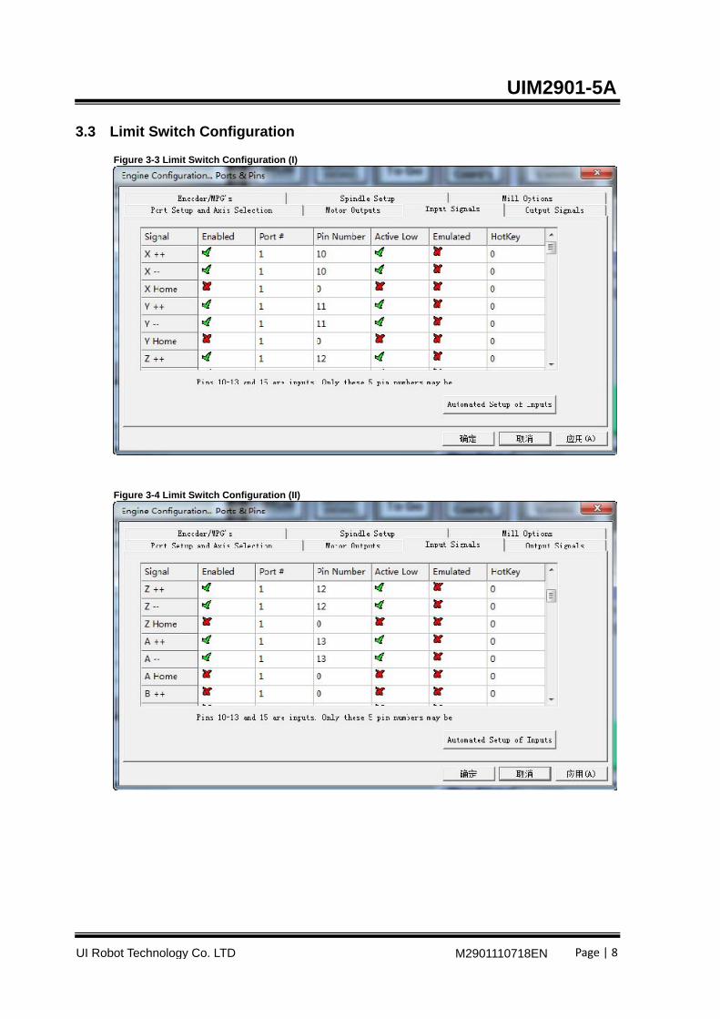
3.3 Limit Switch Configuration
Figure 3-3 Limit Switch Configuration (I)
Figure 3-4 Limit Switch Configuration (II)

Page | 9
UIM2901-5A MACH3 Breakout Board
UI Robot Technology Co. LTDM2901110718EN
3.4 Emergency Stop Switch Configuration
Figure 3-5 ESTOP Configuration
3.5 Motor Drive Enable Feature Configuration
Figure 3-6 Enable Configure

Page | 10
UIM2901-5A
UI Robot Technology Co. LTD M2901110718EN
3.6 Charge Pump Feature Configuration
Figure 3-7 Digital Input and Output Circuit
Page | 11
UIM2901-5A MACH3 Breakout Board
UI Robot Technology Co. LTDM2901110718EN
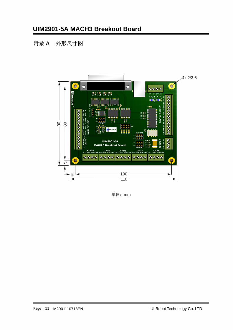
附录 A 外形尺寸图
单位:mm
1101005
90
80
5
4x 3.6