ui. a pregision maghining manuals/da models/da... · a pregision maghining genter for volkswagen...
TRANSCRIPT

tlui.q.
A PREGISIONMAGHINING GENTERFOR VOLKSWAGENENGINE REPAIRS
BORES GRANKCASES,GYLINDER HEADS AND
GYLINDERS
-quick setup-fast production-high precision-simple to use
LCWER LOCATORCAN BE ADJUSTED
2OO'42
MODEL E}A-\f\A'

I
\iezoo-39-to
tr tv2O0- 36-1A ,12OOC.C.200-36-2A,1300C.C.200-56-3A,15O0c.c.
1600c.c.
,v-\A7- CYL._TI]EAD E N D..
CLAMPSTUD
DA.VW STANDARD TOOTSI hand crank for manual feed.
dial depth indicator assembly.tool setting micrometer assemblyset centering fingers.centering bushing for cylinder heads.sharpening frxture .to control cutting toolangles on rnachine mounted sharpenlng wheelthrust facing tool brt.standard borrng tool.boring bit for 4th marn bearing.
DA.VW BARNet weightGross weightMeasu rementscrated
140 lbs185 lbs.
13"x18'x5O"(330x457x1270 mm)
t1
1
DA-VW STANDNet weight 550 lbs.
Gross weight 575 lbs-
M easu remen ts 20,,x22.x42,'crated (508x559x1067mm)
f".&:-
l_J--.-
Multiple cutter head .with preset cartridgetype tools bore main bearings oversize wilha single pass. Thrust is then faced with dialindicator depth control. Back face too, ifnecessary.
20a324 12foC.C.-2 1300 c.c.
1500 cc.1600 C.C.
DOu/N)-200-38-l
2N-37-t
2004(J zDO-37
1 facing bit for cylinder heads-4 tool holders for above operations.I tool puller.1 tool bit and holder locking wrench.1 spacer parallel to support heads and
crankcase halves.1 36 H.P. crankcase locator.i 40 H.P. crankcase locator.
DA.W OPTIONAL TOOLS
Holding adapters and additionaltooi holder and bit for cylinderboring-Porsche accessories.
r rvt LnJU ttLtrrLr! I
Tfr 2oo -3glt3ooL.c.s IS0OC-C.
t600QC2M-39-4r
cENTERINqBL{sHlNq
cYLTNDERS FoR ov E R sr;;';iiiBXjE{OPTIONAL) -\r'-\ rre''
CLAM Peoo -40-,AP/R.ALLEL
19RF l racruq TOoLTBoREs cyUN;'ER HEADSTO INSTALL LARqER CYLINOERS AND FA'ESH EAD S T0 ADJUST'cO M pRESS|ON RATto
I \lI
I
Boring tool machines cylinder location incrankcase oversize forcylinders. :
installation of larger

D,ESCR PT ON
The i'lode1 DA-Vl'J Ir{achine is a rigid,tooled boring center, designed foroperations on Volkswagon crankcase,lie ads.
precision single pointa number of machini.ngcylinders, and cylinder
A Two-cutter head is provided for nost efficient boring ofthe two sizes found in volkswagon nain bearing journals.centering finger capability is included for fisi centeri.ngi-n cylinders, crankcases, or block bores and may be usedfor other workpieces shops nay find convenient to machine ont hi s equi prnent .
A dial indicator depth travel readout is provided to properlycontrol spindle during facing operations of main bearing-tirrust surfaces and cylinder irebd depth control. A1r f eedsand traverses are power operated and controlled from theupper gear housing unit. An auxiliary hand travel is locatedat the base of the feed screl{. power is furnished by endmounted AC single phase 110-220- volt General Erectric motorof 3/4 H"P. 3 phase notor is also available. A quick cr:angelever selects tlso spindte speeds.
Gear housings are aluninum al.1 oy in order to incorporatethe lightcst possible weight rvithout sacrificing rigidity.
NorE: IVhen spindre is shipped frorn f actory the rnachinedsurfaces are protected with rust veto. After uncratirg, useclean cloth dampened with kerosene or solvent and remove theprotective oi1.

Before any fastenings are Iocked it will be necessaryto carefully revel trre rnachine and lock the lower jacilingscrews seated in rvashers so that the Lrase is equatiy,supported at four points on the floor.Place the machine in position using trre two doisers providedto locate it-properly. Now attaclr a dial indicator to trrernachine spindle LuttLr head or tool holders that may beplaced in the heaci. Noiv check to make sure trre spindlerotation indi.cates a maxinum totar indicator runout readingof .0005 or .01 mil limeters in rhe ";;;, plate bore.check this reading-after you rrave rocked tire two spindlehold dorsn bolts and tiren run the spindle dorsn to check theconcentricity of the loiver rocator as d.epicted in figureon page 1*. Total indicator reading should not exceed.001 or .025 nillimeters at any point of rotation of thelorser locatoT,
Jf necessary release and lightly rock flange bolts of lowerlocator and move into the correct position to limit runout.Re-check after locliing f lange bo1ti.
ASSEI'{BLY OF I..IACIIINE COMPONENTS
First page of lrlanual

We suggest, beforethe machine spinclleholding fixture andr"iith them.
CONTROLS
setting up machine for boring, you assenbleapproxinately in position on the workactuate the controls to become familiar
1. Feed lever is latching lever on side of bar.Press down untir rever latcires io engage cutting feed, Todisengage press feed rerease arm which will unlatch Ieverand a110w it to return to neutral position. Lift feedlever until it latches to engage rapid return travel. Bartvi1l autonatically return to neutral upon reaching top oftrav"1: If you wisir to return bar to ireutral wrrile it isin- rtp_td up travel, again press feed release arm wirich rviIlunlatclr lever and alrorr'it to return to neutrar position.a; a safety precaution r{e recommend that the notor bestopped when centering or positioning bar. Inadvertantspindle rotation "nguIement could injure operators otherh.and or damage cutter riead parts. you wiii note stop rodtirat is lield in base casting by thumb screr\r iras a coneshaped end rvliich wirl release cutting feed when it contactslever' This is most conveniently t"Ir"a up and locked bytiiumb screrv in proper position on completion of first borecut. This rod shourd not be used to irold crose toleranceshoul ders .
2. The fast down travel lever is located next tofeed lever' check feed lever to see that it is in neutralposition before actuating. Lever shourd be pu1led dorvnquickly and firmly and not a1 lowed to ratcrret. control isspring loaded and wiIl rerease when you release pressure.This control should be used on slow speed only on automotiveand high Rpl,l machines.
.3: Spin$"lE g-lUp^cJ1 control is tocated to left sideof feed 1ever.'ffr'rf,fii?""dorvn movenent wirl engage spindlerotation and a reverse action will disengage. rn that this isa jaw clutch rve recomnend stopping the motor or jogging theinotor to engage clutch on the high Rpr,{ of t}re irigrrEi speedrnachines. standard procedure is to throrv out clutch uponcompretion of the boie. Turn cutter head around to iniexingdetent- to- position tool to front, then reverse travel. Trresna11 knob on,top- of the upper housing nay be used for manuaIl1,turning spindle rvhen necesiary. on t[" automoti-ve t/pe unitsthis knob is also used for centering.
4. 2-319,t manual travel is actuated by rotatinslrandre attached to spline at top of base. This travel sirourdalways be left in fuit up position after using bar. Normalprocedure is to rapid trlvLl or feed bar to poirrt requiringmanual travel - If back feeding is necessary run hand traveldown first and trren rapid travel down to wlrere toor can be:.nserted.

5. Speedgear housingTirese may beclesiraole totrigher speecl
control is operatecl by pulling knob at motorand raising for ]ow speecl ancr_ lowering for high.changed when bar is running alt,hough it i=jog motor when changing from low t6 high onmachines.

OP RAT l'l G NSTRUCT ONS
l4ain Bearing Resi zing
cAUTI0N: Irlagnesium case and particularly cuttings resultingfron nachine u-"" highly inflamable. A dry chemical powd.erextinguislrer should be available since most other,"ins rvi1lnot extinguish flames.
Install the proper upper locator in the top plate of thework fixture. The locators are marked 1i0b lor s6 cases and1500 6 1600 for the 40 H. p. and larger cases.
Il" lower- plate is machined flat and rilzy aid you in checkingflatness before case assembly. Be sure dorvel pins and bearfngliners have been removed from bores. Be sure burrs and highspots- are completely removed from case half and carefullyassemble halves, torquing the fastenings to the manufacturersreconmendations.
Check both thrust areas andanount of oversize requiredthrusts.
bearing bores to cieterrnine theto the bores. Ileasure widtit across
Now place the upper main bearing boring tool holder and cutterin the rnicrometer to set to the bore size you rvish" carefullydo this operation in accordance with microrneter section andauto boring on1y. Place the set tool into the upper tool slotand repeat the process rr'ith the Znd lorver toof n-ofder and offsetbit that rvi11 contact the 2nd rnike anvil in the mike frame.This offset bit, due to the sirort length of holder and bit,is more difficult to set exactly and ionsiderable care must betaken. An extrernely light screw tension on tire tool bit flatyill !u1p prevent excessive growth in the tool when locking.Lightly lock set tools into slots rvith set screws.
Now instal l case in f ixture and rvind up lorver locator unti 1tight and then back of f lorver han<i1e a half turn. This wil la1low a preset spring tension to hold case properly witlroutdistorting the case or fixture.
Not" simply turn on motor of boring spindle. careful ly rapicitravel upper tool to first bore, being careful to avoid overtravelling. Engage spindle clutch and then feecl 1ever. Boringmay.be done on high spindle speed.
lfatch for completion of the last bore by the srnaller tool andt:t feed ltop rod to immediately stop feed. Disengage spindleclutch and rotate or a11ow spindle to turn to indent positionand engage rapid return travel. Remove upper boring too1.

caution: Always turn rnotor off unless bar is actualry nachiningor necessarity travetling. Inadvertant spindl;-;;;;11"" ";t;;;:ment could injure operator or danage machine or work.
Now set the dial depth indicator to aIlow the exact anount thatis required to face fron thrust and proceed to that point. Retracthand feed and then poyrer feed to ".rou" case,
RESIZING CYLINDER HOLES IN CRANKCASE
Note: Renove upper l0cator in DA-vt{ machine for both the fo110w-ing operations. Operate on high speed.
0versize boring of cases to accept larger cylinders utilizethe upper tool holder arrangenent. centering fingeri are usedto locate bore concentric t; spindle and case harf is held downwith stud through adjacent bore as shown in figure Ir.* Rernovetool holder and tool bit before centering. Do not use excessiveclarnp force, distortion of the case will introduce.rrindernisalignrnent when reseating cylinder flange faces.
.Ptoperly sharpened generous raked tools alrow one cut to openbore to size and nachine can be operated on high speed. l.{achinebores to -008-'010'or .zo to .zs millineters over noninarcylinder size. Limit depth of bore to a little more than theskirt length on the cytinder, since this will leave more netalsection where it is needed in the cranlccase.
To nachine vtrl head it will be necessary to instarl a head supportparal1e1 on the lower work table. This fixture must be lockeddown to the table by four bo1ts. The vl,ir heads are held in placeon the parallel by ? cranp and cenrered to the boring spindie byneans of a concentric bushing which is sinply dropp;; into theVIV head bore.
An offset tool bit is used for boring and facing of v}tl heads andis to be used in the lower tool srotl rne toor"setting on thenicrorneter will be correct for this diarneter only if used on anoffset anvi1. (Note: Always bear in mind it wiir be necessaryto make allowance on rnicroneter size setting when using a straignttool bit in the lower tool slot.)The procedure for the machine vlll head is as forrows:First, install head support parallel. on Iower work tabre.second, place vl{ head on support paralle1 rvith one head cylinderb?t-u directly -under spindte,' ttren lightly clanrp head. (Fingertight only) (Note, itocker box "ouui nounting surf,ace on headnust be flat so that head does not rock on support paral1e1. rfnecessary, dress off burrs, sand frat or shin, this is requiredfor all head nachining operations.) Now prace centering bushingin head bore and hq.nd"traver the "utt", head into thir_ !urt,i'g..This will center
"t by tight_ening the nut of the clarnp. (Note: Excessive cr*rnp force candistort head'.torque ctamp nut to 30 foot pounds.) I; sone appli-cations, a slightly highei force is required.

i*
Third, set offset tool bit to cut rerief_bore approxinately 3/grtor l0 millimeters under lh" finisf, ^ jor" si ze. fhis wi.ll allow afine accurate seat for t'e .yiin;;r-;n !h" finiri'-.r.. (Nore:Al t iread macrrTing op"trrions ";;-;";l feed operations and areperforned simil""Iy in-uoti, .yrina"r"ior", ,nd arso ro equar diarindicator dgRths - )' ii.il' wi 1 I inrur" i1"a the bore sears wi l 1remain paralrel and in .n exact line with each other.
Fourth' set offset tool bit for finish cut and insert into cutterhead' hold to-ol up and-in to cutter head wrrrie i".ti"c set screw.(keep a fini;1_raci"c-.";r bit ,"i-ri-qossibte). Nou nake finishbore and facing cut. If shims,r" u""a to support head, be sureto kecp shims in ,"r" ."i"a:.onsir;-p ;;;" moving- heaa to second hole.It is not necessary to remove the offset rread-facing toor andi;j';i":nil :;:';;::r"::J .rlinder h".J -i;-;;;;'i,^"laken to clear
An occasional check of the. accuracy of these two counter boreseats can be made with " ai.r irJir"io, attacrred to the spindle.8v properrv p::r:ioning*.i" dial, t;;-;"n tip the head on theparallel and sride it;rJ"r tir" ai"r:.naicator, when set the dialto ?ro" and check
"ur.ti;;'readings in-both ,""i, ;; s iiding trrehead. you must again nake sure it," head ;";;-iiuiron arr sides,if necessary :lir in arti"" praces for i""e point support. Dialreadings shourd be .";;iJiur,t. If. th"y, .r.. .003 rrigirer front toback, they should be ;h; -J"r" in the o'an", bore, to a maximumerror of .0015. If tire reading is .ooi.different frorn extreneoutboard sides of lo""r,-Ine iiu;;r;'ria", sirourd u" increnentalbetween mininun and maxiru*, to a maximurn of .o02._ -
The crankcase halves bores may be checked in the sane nanner tornsure correct seating oi-.ylinder ;;-;;sembIy.
i;3":::;i":::',;lilll;'"illiiol:. "ouidistant rron upper hub to
Note: Remove upper cyrinder rocators and case mainline rocatorswhen doing head work,

'SIIARPE}i NG CUTTE
Ihe performance of your boring bar and quality of tvorllit will do is alnost entirely dependcnt on the care of thecutting too1. It is the rnost- frequent cause of size andfinish problems in boring.
To sharpen tire carbide bit insert tool holder in sharpeningjig s1ot. Place the jig over the pin provided on the top ofthe motor l'iousing and sirarpen bit on the sma11 diamond tvlteelprovided on the motor shaft. Aiways make sur.e you sliarpenthe tool on the side of the diamond tirat is running toisardtire top face of tlie bit. Sharpening on the wrong side canreadily chip tire point. lVhen sharpening use very lightpressure, moving the tool back and fortir across the diamondwheel to improve cutting and prevent grooving of diamond.After sjtarpening a number of times dress excess ste&1 arvayf ron carbide on grinding whee1. This rvi11 f aci-litate use ofchip remover hoods and nake for quiclier sharpening. Diamondwheel is designed for carbide on1y. Steel tends to load it.A tool bit used for aluminun boring should never alternatell'be used for cast iron or Steel. Iron or steel weld on topof the bit rvil1 cause a rough f inish on aluminum worl<.
FACING THRUST
if it is necessary to back face thrust, set the tool providcdto tite proper size, travel the spindle down so the tool maybe inserted through the cylinder opening,
Pre-travel hand feed down as previously mentioned so backfacing travel will be available. Position back face tool atcutting point so an immediate short travel rvil1 clean theback face area.
Remove tool through opening and return rnachine to top, Ifback facing is done it rvi11 be nolt'necessary to again measureacToss the thrusts to determine necessary Stock removal fromthe front face.
lileasuring devices can be purchased particularLy on largercases to neaSure in the rnachines, or the case may be renovedf or Ine asuring
Now place and lock a properly sized front facing tool in th9,-,pp"t slot and set aiif depth indicator so it is oPerating ontool contact witlr the work.
Contact of tool witir tire rvork can be better observed if tlte faceis marked witir a black penci l. The nachine nay be hand-tTaveIed to the face wiih spindle rotating or spindle stoppedand hand traveled rotating spindle by hand to determine exactll'when face is contacted.

The DA-vw machine may also be used to clear the outer headsurface, should tirere be interferanse with the cylinder after9?"pening bore. Make cut,s of about L/2,, or rz nillineters indianeter increased in one cut.
CYLINDER BORE !ESIZIN6.FOR OVER SIZE PISTONS
To bore cylinder (.040 nraximun) over size, itto install the proper upper c"ntering locatorplate of the work fixture, and to initati thetube over the lower locator.Then place rhe cyrinder (head end dorvn) you wish to bore intothe recess in the support tube. (Notei cylincler nust be seatedin its proper step in supporr tube.) If rs00 or r600cccylinder are to be boredl, set iled stop rod so that tool bitdoes not travel over l/ grt beyond the "r,i of the cyrinder. Thenwind up the lower locator until the cylinder is seated andclanped. Do not back the cranp off on cylinder boring, sincedistortion ir n?t a problem "rd cylinder requires more clampforce. Now, using the upper tool srot set a seperate toor, oneyou do not intend to use lor case or head borin!, then withnachine set at low spindle Rpl{ proceed to bore "yiinder. Afterboring is complete, disengage rp:.nare clutch and rapid travelmachine to up position.
will be necessaryinto the toplower support

rf tool is properly sharpened place cutter and proper tool holderin micrometer. riold tool bit rightly against mike anvil anciloosen A1len screw witir wing wrench,- Gently let toor holdersLide back to make contact witrr micrometer ipinclre. Thisprocedure will prevent chipping carbioe. rhis micrometer is .050to a revolution rather than .025 as on a conventional mike. setmike to size you wish to bore and tighten set screw lightly. ---Back off mike and tighten set screw. Here agai-n excessivetightening only tencls to nick mj-ke anvil and rna]:e future settingdifficult. After tightening recheck sizeMake sure tool holder and tool hol-der slot in head are free fromdirt- Insert tool in slot'makj-ng sure it is completely back ancllatched. {.ightIy lock set screw with socket typ. screw driverprovided with tools.
BORIIiG AUTOI"IOTIVJJ ONLY
FOR CHIP REMOVER USE ONLY
manual feed is provided for use in counter boring,flusir etc. A optional dial inoicator de1:th ofavailable for accurate control of counter bore
rnsert proper length vacuum hood in hole provj-d.ed in cutter1."9 and press in untj-l tool bit. tip extend.s out of hole inhood at least .025. rnsert vacuum gooseneck in balr bearing ontop of centering knob. Start vacuum motor.
BORINGEngage spindle clutch and latch feed lever j-n down position,I{hen bar has completed boring, set stop rod so l-evei will bethrown into neutral- position. stop rod will- then be set for theother holes on the same cylincier block.Disengage spind.le clutch. Turn cutter head to front positionand latch feed lever in up position. Turn off motor, Removevacuum hood ancr tool holdlr-with tool pul1er. (always removetool holder after boring. ) Loosen anchor bolt ano pioceed tcnext cylinder. If bore is to be chamfered witir bar this shoulobe done before loosening anchor bolt.If vacuurn is used a .cylinder block can generally be bored beforeemptying dust bag. Keep bag and f ilter cl-ean, An oi1 saturateclbag or filter will restrict the flow of air.
CHAMFERTNG
A special tool is available for ciramfering. Tool may be set byeitirer inserting ln head and approximately setting oi place inmike and set approximately .100 over bore size. chamfering maybe oone either by using feed ancl releasing when aoequate cilamfEriras been oevelopeo or by use of hand feed.
COUNTER BORING
The slow travelfacing sleevescut reao out iscreptirs.

AUTO}IOTTVE
Boring Bar OPERATING fNSTRUCTIONS
. CII,ITERII.IG FINGERS
centering fingers are a<leguate to center the new bore within.002 of the centering of ord bore; providing the old bore isreasonably round and if you forlow operatinf instructions1:roperIy. centering fingers can be lapped feriociicarry toobtain near perfect centering. use the-foliowing proceclurej-n an undersize bore or junk block.
4.
1.a1.3.
1.2.?
Bore hole and remove cutter but do not'nclamp bar.Rapid traverse bar down into holeExtend fingers and
_ exert pressure on them against cylinrJ.erwall- while rotating inner spindre knob to left by hanci
( counter-clockwise ) .After rubbing, examine points on arl fingers to make surethey are all rnaking contact.
TO LAP PII.IGERS
Diamond Sharpening Diskhandled with care it will- provide many
T'1ICROI.IETER
Your,boring bar micrometerr ds with any other measuring, tool,should be used del-icately and with care to be assured of thegreatest accuracy. particular attention should. be paici toinserting the toor in micrometer without allowing tiol bit tosnap into mike anvil. Care should be usecl in the method oflightly locking tool bit before tightening.After a period of use you will note that the tool bit tip willfgfg" a depression in the micrometer anvil. This , of course,will result in inconsistent sizes, particularly aiter resharpeningtlte bit. Periodically we would rec-om*"rrd turning the anvilslightly and finally end for end so that a frat iurface isexposed to the tool bit tip.
SETTIi'JG I'1I CROI{ETER
Bore a hole.Remove tool hol-der and bit and place j_n mike.Adjust mike so that it reads the same size as the hole you
have bored. Small variations may be made by turning themike sleeve with spanner wrench proVided. Larger cirangesshouLd be made by moving the anvil.
DIAI{OND WHEEL
CareIf the diamond diskyears of service
ofis

occasionally diamond surface can load up if steel part oftool bit is not ground back as sharpeniig instructio.rs indicate.To clean disk apply a smal-l amount of sorvent or thinner andrub off.
LUBRICATTON
Upper Housing should be packed withoe. F2 LugE.boring cycres,Ilotor gear housing should be re-packed with 3 parts Ebon cupliglt grease, 1 part 30 weight mlchine oil- .ppio"i*alery every50r000 boring cycles. A'very occasional arop-of oil in themotor_ gear pot (socket head screw near botLon) will help main-tain lubrication at right consistency,
T":ty 2 days of operation fitting at, top of spindle sirourd belubrj-cated with Ebon cup 1i9ht gi"."" flr top'inner spindlebearing.
+ f:r drops of oil put in appro:cimately every 500 bores in holein key way of spindre wir-l [Lep spindlS lubricant fruici.
Union OiI Uh3OBft Fiapproximately 25,CIO0
ADJUSTMEI{T OF OUTER SPII,JDLE
itlain spindle bearings are tapered sprit cast j-ron rings heldi-n seat by adjustment nut. Tension on bearings is normarryadequate to require no acljustment f or many i:oiing cycles.caution should be used in adjusting tirese bearings in order toavoid a too tight spindle which o.r1y serves to wear out machineand make control operation difficull. rf it should be necessaryto adjust proceed as follows:
upper bearing. is adjusted by removing f ert retainir-rg nutat top of base forcing felt up and adjust nut with pur:ch.For lower bearing first back off B-32 set screw at bottonspindle bearing. Then remove feLt retainer at bottom of base
and turn nut with punch.1. Place and clamp bar over hole or overhang so spinclle can berun oown. Loosen set, screw and. both adjustiig nuts.2, Tighten upper bearing until adclitional pressure is requirecrto operate hand feed.
Repeat tiris seguence on lower bearing taking carethat hand feed operates only slightly tighter.
3. Traverse bar at all points of travel and make sure itand feedworks easily. spindles are ground slightly tapered to securemaximum rigidity at lower limits of travel wirere it is mostrequireo.
4. spindle adjustment may arso be checked l_ry f eeciing spinrllec.town and pulring slacli oul of feed mechanism by forcing clownupPer irousing. pressure required shoulcr be 50-75 rbs.
1. Remove two screw and sniarr cover on back sicre of upperhousing.
2' Remove stop set screw restrictlng up travel of spincilecl-utch lever and move lever to fui-I ,1p-i"=ition.3. T1=:r! pin (oiam. .180 or less) in one of the holesprovideci in the o D of take up nut. (see inner spinclre nut.)liold spindle knob with one haid ana turn take up nut to right(clockwi-se). you wirl note the nut ratchets in notches as youtake up' Take up untir spindle is tigr,t and back off 3/4 toI r/2 notches. nun bar oi high ;;";a';king sure there is9"1y slight heating at bottom of spindte. rf ireat is excessiveback off one notch furtirer.4. Replace cover ancl resetclutch lever to stop in its
spindle clutch stop scrcw to al_lowupper detent.

liote: rf excessive load.s are imposed on your boring bar thefollowing occurs:
1. Tirrust loaos rf bar is fed or rapid-travel_led into objecttfat imposes an excessi-ve t\rust 16acr on spind1e, the tsrassThrust i{ut Part t,lo. 5r9- \1 will probably Le sheared anct re_g\ri5e replacing. This accident c-ould haipen with spind.leeitjrer rotating or stationary.The effect of this will be for the bar to continue to runbut with no feecl or clown travel working. rf bar is l_eft infeed or down travel-, drive spline will be purlecl compreteryout of mesh at which point motor will continue to run but -feed screw wilL not turn at aLl.
2. Radial loads If bar has a tool in cutter head tirat turns intoan-object an excessive rad.ial shock will be imposeci on spinoleand_rvilI probably shear motor drive key No. sob-az. Thiswould 1ike1y happen only when spindle drive clutch is in.
trXCtrSSIVX LOADS
The immediate effect of this wilr be for the motort9t turning any visible parts of the boring bar.of the speed cirangre lever will indicate the lowerentirely inoperative,
only to runA movementgear box is
Note: This j-s the onlyI,lotor Drj.ve Keymachine spindle.
disassembly requiredin cases of excessive
SECTION B
to replace I,licartaradial Load on
long motor screwsnot to lose soringreassembly.up stator out of
Remove fan shroud cover and shroud. Remove 4and l-ift off motor fieLd assembly. Be carefulrvasher on top bearing, and repla-e properly inLay blocks or shims on bottom encl bell and prydrive to remove stator.
GN},IERAL I,IATNTB}JANCE AND TROUBLE SHOOTING
I4ost problems possibLe wj-th portable boring bars wiIl, be readilyovercome if carefull attention is given to proper tool dressing.si-ze problems will rerate largely to the carefull use of thecutting tool, tool holders, ancl mj-crometer. These parts must bemaintained in good order.At least a yearly inspection should be macle of both the inner andouter spindle adjustment as noted in this manual.sltould there be a tendency for the machj-ne to chatter at thebottom of the bore and tire tool bit is in proper ord.er, it will benecessary to clean the dampening counter weight 200-78 in thecutter iread. (see sec. B-B) Remove the 4 head screws, the headlld "arefully clean the counter weight and cavity making sure itfj-ts freely back into place.

DISASSEMBLY OF I\,IOTOR HoUSING
Note: Motor housingupper housing
be removed without oisassembly offeed screw.
mayand
SECTION A-1Remove 2 hex socket screws on bottom of 500-97 hand feedbracket anci 2 scr.ews holding 500-96 prate to 500-70 housing.Turn out (counter clockwise) bevel gear.Remove 4 flat head hex socket screws in 500-70 housing. Liftout screw, or if upper irousing is still intact hold in rapiddown 1ever, 500-30, and rotate screw counter crockwise unlilfeed screw is crear of motor unit. on reassembly it may benecessary to rotate motor and screw, using care in aligningspline in gear to match scre!,/ sprine. Ir1a[.e sure threaded feydoes not jam on entering s1ot.
REMOVAL OF FEED SLEEVE AND BEARING
i'lote: For removal ofnot necessary
brass nut only.to remove motor
SECTIOI.I A-2
(This disassemblyhousing) ,
].S
Remove snap ring set screw 5002-185, and press sleeve assembly,500-73, off bearing. tsack out socket set screw from brassthrust nut and screw off nut. Bearing may now be removed fromshaft.
REI{OVAL OF MOTOR iIOUSING
To remove motor housing take out 4 bolts in housing flange.Note: rn reassembly motor alignment must be check after screwsleeve is in place before flange bolts are permanently rocked..Use surface plate over screw and spindle,
To disassemble irousing, remove pin and 5 screws and bottomscrew in middle of bott,om of gear pot. Remove set scre\{s androll pin on speed shifter lever
Tap lightly on motor pinion | 500-64, and screw drive gear, 500-69ano housing will come apart. Pinion shaft, 500-69, with cJutcirand gears may be tapped out with small punch through center ]ro1ein bottom of gear pot.

DISASSI'MBLY OF UPPER IIOUSTNG & SPII.IDLE RtrIVIOVAL
Remove 500-16A knob by releasing socket set screrr. Remove500-17 knob by releasing socket set screw. (on automotive unitsyou may then draw out centering rod.). Unscrew spindle clutchlever stop screw 500-30-4. naise r.ever to extreme top, whichwill al-low removar of countersunk screw and lever assembly.Rernove cap screw to disassembre trip lever, 500-35. (caution:Don not lose. trip spring) . Remove k screws holding upperhousi4g sections-to-geth6r and lift off upper l_id, 500-22.Now shiftino lever 500-38, with spring may be removecr alongwith 500-25'upper fast r.i,rr., g-ai wi-in.plunger and spring,spindre ct-urch and key 500-3, 6a1l beariirg *itr. l.[.-,rp spring500-18, (be sure_gnrins is reassembled properly), sleeve gear500-1, feed nut 50b-2, and. feed g.ii-rilr, Lnr.r-si washer 500-u.rf tire bar is in a verticar- spindle position we suggest youplace something unoer the spiiate ro!" to prevent lubricationfrom. running out and then remove 500-5 spincrle nut. Nut canbe started off through adjusting ..."== hold and then handturned- Now drive gear alseTblf 500-6r ildy be worked off arongwith 500-4 spacer ano wooclruff l"y, - '
Inner spindle may now ]:e removed,,2u cap screws in upper housing should be removecr and housingmay be driven.off spindle. IJeat on housing will simpr:-tyremoval of this sweat fit.Lift off of feed screw.Nut sitould be removed from 500-29 shaft and siraft may be pressec.rout with gear500-7 19tg gear with radial ano thrust bearings may be removecialong with oi] seal_.
lixtreme care should be taken when removing long gear out ofseal or seal out of housing. seal is traiite irra garter springwill come out_easj-ry. I{hei reassembling, open seal as ronggear is pushecl i-n to prevent garter =p=ing iro* snapping orrt.RAPID RETURT,I TRAVI]RSE
ff the boring bar shoulcl ever fail or hesitate to return to topof travel when shift Lever is l-iftecl and l-atched., the followin!procedure may be used to acljust return traverse crutchesI. Run bar down into hole a few inches.2. Loosen set screw at top of upper housing, (Refer sec, A-A)3. This will alrow you to tap rapid return tumbrer assembly,(Top of shaft located on top of upper housj_ng opposite spinltteside down slightly which wirL resurt in deeper engug"menl ofcl-utches. Adjust tumbler shaft so that when shift lever is inneutral, clutches do not clatter. clutches should engage immeo-iately upon latching lever.I- Tighten set screw to relock shaft. Check to see acijustmenthas not been changed by set screw.

3T0p ril{ .r.ij!i]:|Ly IN 5oo_3 SLL-1CH :jLlE'/Efor (o]-d- a.nd new st-:le ball_ detenl;)
:iefer to ihe uDper housln8 dralvlng for the old end nevi balldctent str,'les. Fress r1n lnto correct clu.tch sleeve holeto tne he1:ht sho',rn belorr.-lhe Durpose of t}:e ball detent 1s to stop the splndle fromturnin: wlth t}-e tool blt faclng the macli-ne oplrator. Thenew stlle has th?-- acva.:etaqe ol belng able to aaSust the balldetent nlunger, saz-z-Lg, from the 6utsld.e rvhlle the oldstrle hed to be taken out of the Llpper houslne case to b,eai.juls;ed.
-l'.ssenb1e clutch i-n upoer irouslng a:rd ad,Just the ball detentpIr-rncer sD il:re.t',rhen lhe machlne is icl-ing and tire splndleclutchi 1s dlsengaged, the splnd1e 1vl11 stop turnin,q ivlthlhe fool blt facing thre machlne operator.
-+-137' \:-
NEW STYLE -\_
OLD STYLE
1.20:-1.?? NEW STYLE
- l.\i oLD srYLE
,l\,;,I
NEW STYLE
v
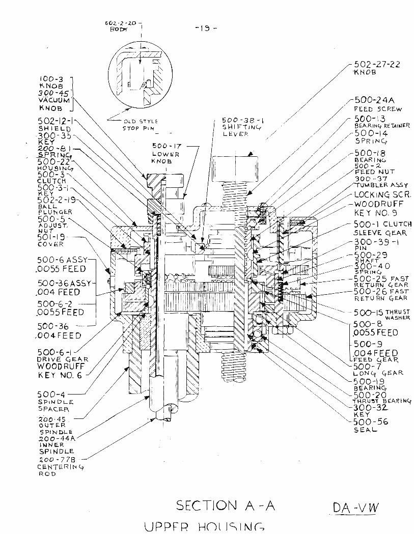
602-2-zo - -t3 -
too -3KNOB3 9!'+sVACUOMKNOB
BALLPLUNqER500 -5AO.IU Sr,NUf50t-t9COvER
50O-6 ASSv.OO55 FLE D
50O-36 ASSY.OO4 FEED
50G6 -2.0O55 FEED
500-36.OO+FEED
500-6 -lDRIVE qEARWOOD RUFFKEY NO. 6
500-4SPTN DLESPACER
2(.j0- 45OUTERSPINDLE2c-0-44AINNERSPI NDLE2oo -7 7g
cENTERtN qROD
OLD S'TYLESTop prN
500 -38- - |SHltrTrlrQLEV EP. ,/
,/ FEED SCREw
,/ r 5OO-l3,/ / BEARing REATNER'/ .,/ "
50 o-14,/ SPRrNc,
'/ .r' ,-5OO-18
502 -27 -22T( NOB
r5OO-2qa
./-JUL,'-I'J,/' BEAR I N(,' 50a-2
/FEED NVT// 30o -.3'lMBLER ASSY
LOCK tNq sc R- -woQDRu FF
KEY NO.9
-L 5OG-15 rHRusrWASHgR
500-BPO55 FE ED500-s.oo 4 FEE DFEEb ({EAR500- 7LON q C?EAR
5 00-19
9 EAL
600 - t7LOWERXNO B
5oo- I cLUrcHsLEEVE qEAR300 -39 -lPIN500-2sSHAFT300-.4 05PRING5OO-25 FAsrRETURN G EAR5OO -26 pnsrRETURN qEAR
--'
"-'-'t'-
SICTION A -A DA -v tv
\ --. BEARINq. \ "-500-20\, \ 1{R!3r_E}EARI}rq\ '-300-32t\ KEY
"-500-56
UPPFR' HOt ISING

./ _soo-7+/ / FEED sLEEy€ BEAFTNG
r j / i/t///-
roo-264DIAilOND TvHELLzoo- 80
DlAtt XT A)ApTOR?oo- g2Fj^* s HRouDL9VER
7- 5OP -Z-30/ FAN SHRouD
5002 -l8sRETAtNIN6 RIHG
zoo- 452OA15< OUTER SPINOLE
SHIiTNaPrNo,_E
//-/ , / // BLonzE lHelST NUTi / ,/ ,- 5oo-7J
/ / / /FEED sLrEyE + ilur ,// // ./, / / f----ry-//t /. / T---:-
2ao-44AINNERSPINOLE
500-ErFELr w^sHER
//// *J/ /,tN
//
2oo-ts-2OUTT.i SPINOLEt{ARrr.c
700- 26NUT
soo-6OUPPER FEED
SCREw prr. Etr.nrrvc-
500-60,4MOTOR EEARING
500-6tMOTOR COUPLING
500-62KEY
5oo-604UPPER PINIONEEARING
5000-156RETAININC RING
SPEEO GHANGE CLUT'CH
500 -64MOTOR PINION
5OO - lOINTERMEOIATE GEAR
500 -t I
L-oW SPEEO GEAR500-7tLOWER MOTORGEAR HOUSING
500-65LOV/ER PINION BEARINC
500-70UPPER MOTORGEAR HOUSING
PINION- 16 TEETH
rEET-H
20 TEETH
5r06 -,ooREIAININC RINGS500-6c^L-OYYER FEED SCREWPINIO}J BF 1RING
\ ./ RrrAlru\ ,/ too_ 35i--_ -/
FELT w^
/___ -
.5EE NEX-I-
500-69
500 - 68FEEO SCREWGE^R SHAFT500-a7 tz
M^-fN_FEEo scREw DRIVE cEAR500-86 24 TeETHFOP
-MACHINE5 AFTIR StrRIAL NO.5I53_1JEE To THE FO LLowtNG PAGLSECTION B-B FoR SPtNDLL Aat'yS.
PAGt:

200-44AINNER SPINDLE
5 0 r-74OIL SEAL
2 0 0-toCEN TER ING F I NG ER S
oPTJONAL-2c,0-30_/CUIT€F, HEAD CAPBLocK BoRtNq
8EFLR. To DA_ V WTOOLI N G pAGE
200-45OUTER SPt NDLt
200-30
6 00-5CUTTTN HEADnn , ^ CAP
' uPpEnCUTTER HEAD
200-31LOWER CUTTT N
HEAD
DA:V!SPINDLE ASS Y
{OOL LOCK SPMNG

500-94
500-98
500-97-2
500-24t
50t-23
5002-t6ssoo-74500-4tsooro-l
soo-73
500-70
SECTION-C-C
HAND FEED

300-37TUMBLER
500 -2sUPPER FASTRETURN GFiR
500 -26LOWER FASTRFTURN GEAR
500 -2EPIN
500-27SPR,NG
GEAR SHAFT300 -29FAST RETURN(wtrH NUT)
SECTION D-D
5HIP\f,fl6
LATCH SCREW
5oo_33 _
DETAIL F

500-30RAPIO-OOWN LEVER ASSY.
RAPIO-DOWN PIN
OLD TYPE
NE W TYPE
DETAIL E
DLE CLUTCH ASSYS
5@-66-5INDEX PIN 5oO- 3t- z
ARM
500-3t-lACARRIE R
RETAINING RING
500-31- I
CARRIER500-3t- 3L EVER
t
eI
oII
500- 3t- 3ALEVER
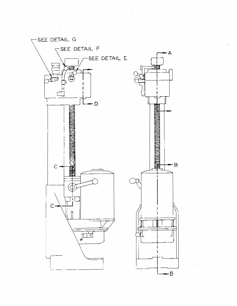
SEE DETAIL
SEE DEIAIL F
SEE DETAIL
I
I
I
II
I
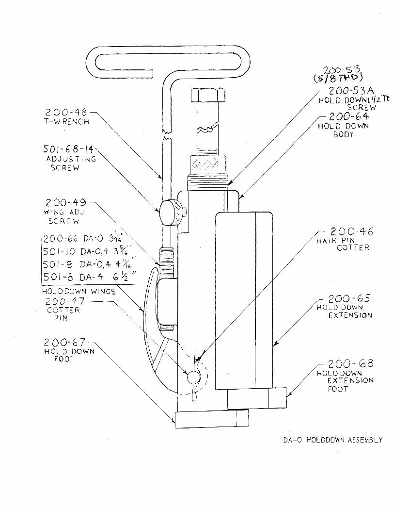
Zrc-s3.15 lsrtsD)
200-qgT_W PENCH
50/- 6 s-t+ADJUSTING
SCREW
200- + eWING ADJ,
SCREW
20 0 -66
50 t- to50,-950t-g
DA-o 3l)DA-O, + 37r"DA-0, 4 1'tr"DA-+ 6lr"
200-53AHoLD DowNttlzTt
SCREW200-6+
HOL D DOb/NBODv
,/' ?OC'+6HAIR PIN
COTrE n
200-65HOLD DOWN
EXTENSION
?oo- 68HOL D DOWN
EXTE NSIONFOOT
HOLDDOWN WINGS200-+7COTTE R \
PIN
2 00- 67HOL D DOWN
FOOT
DA_O HOLDDOWN ASSEMBLY

DA- VI{ TOO L I NG
199- 89
rca-74199-90
501-31
100-76199-94sot- 33D199-96
l0 0 -2s-5200- s2-t200- 32-2240-36-1A200-36_2A200-36-3A200- 37200- s7 _ I200- 38_1200- 39200-39-1D200-39_2200- 40200- 8s20a-40-1A2oo-ro
l-I12n Tool holder (case thrustheadDouble sided facing bit1-S/ltr tool holder (casehead facing)
bearing) us ed in upper cutte(case thrust bearing)nainline, cylinder hole in case,
RB carbi de toor bit (case mainline, cylinder boring , cy-linder hol e in case) used in "pp"r'"rir"_ h ead0ffset bit (head facing) used. i; lower cutrer head2-714'r Tool holder (chamfer head) used in lower cutter 'ead30o Chamfer bit (chamfer head)1-r/4'r tool holder (4th main bearing in case) used in rowercutter h e ad
Of fset bit, I'r long (4th main bearing cas e)Upper locator; case l200ccUpper locator; case 1300_160OccUpper locator; l200cc cylinderUpper locator; I300cc cylinderupper locator; lS0O_ I600cc cylinderTubing ad ap t or; cy I i n derSteel tubing; cylinderLower locator; l20O G l300cc, 1S00 & 160Occcentering busrring; r 300-Is00- re oocc'cyii'a"= headHold dorvn clarup; (short) cylinde,r heai 1300-1500-1600ccCentering bushing; t200cc cylinder headParallel case supportIlold dorvn washer; caseHead support paraIleICENTER,ING FI NqER