ufgs 04 20 00 unit masonry - wbdg 04 20 00.pdf · book. masonry not meeting the above definition...
TRANSCRIPT
**************************************************************************USACE / NAVFAC / AFCEC / NASA UFGS- 04 20 00 ( November 2015) - - - - - - - - - - - - - - - - - - - - - - - - - - - - -Pr epar i ng Act i v i t y: USACE Super sedi ng UFGS- 04 20 00 ( Febr uar y 2011)
UNI FI ED FACI LI TI ES GUI DE SPECI FI CATI ONS
Ref er ences ar e i n agr eement wi t h UMRL dat ed Apr i l 2018**************************************************************************
SECTI ON TABLE OF CONTENTS
DI VI SI ON 04 - MASONRY
SECTI ON 04 20 00
UNI T MASONRY
11/15
PART 1 GENERAL
1. 1 REFERENCES 1. 2 SUBMI TTALS 1. 3 QUALI TY ASSURANCE 1. 3. 1 Masonr y Mock- Up Panel s 1. 3. 1. 1 Mock- Up Panel Locat i on 1. 3. 1. 2 Mock- Up Panel Conf i gur at i on 1. 3. 1. 3 Mock- Up Panel Composi t i on 1. 3. 1. 4 Mock- Up Panel Const r uct i on Met hod 1. 3. 1. 5 Mock- Up Panel Pur pose 1. 3. 2 Speci al Masonr y I nspect or Qual i f i cat i ons 1. 4 DELI VERY, STORAGE, AND HANDLI NG 1. 4. 1 Masonr y Uni t s 1. 4. 2 Rei nf or cement , Anchor s, and Ti es 1. 4. 3 Cement i t i ous Mat er i al s, Sand and Aggr egat es 1. 5 PROJECT/ SI TE CONDI TI ONS 1. 5. 1 Hot Weat her Pr ocedur es 1. 5. 2 Col d Weat her Pr ocedur es
PART 2 PRODUCTS
2. 1 SYSTEM DESCRI PTI ON 2. 1. 1 Desi gn - Speci f i ed Compr essi ve St r engt h of Masonr y 2. 1. 2 Per f or mance - Ver i f y Masonr y Compr essi ve St r engt h 2. 2 MANUFACTURED UNI TS 2. 2. 1 Gener al Requi r ement s 2. 2. 2 Cl ay or Shal e Br i ck 2. 2. 2. 1 Gener al 2. 2. 2. 1. 1 Sampl e Submi t t al 2. 2. 2. 1. 2 Uni f or mi t y 2. 2. 2. 1. 3 Recycl ed Cont ent 2. 2. 2. 1. 4 Ef f l or escence Test 2. 2. 2. 2 Sol i d Cl ay or Shal e Br i ck 2. 2. 2. 3 Hol l ow Cl ay or Shal e Br i ck 2. 2. 2. 4 Ref r act or y Br i ck
SECTI ON 04 20 00 Page 1
2. 2. 2. 5 Gl azed Br i ck and Gl azed St r uct ur al Cl ay Faci ng Ti l e 2. 2. 2. 6 Sal vaged Br i ck 2. 2. 2. 7 Fl ue Li ni ngs and Thi mbl es 2. 2. 3 Concr et e Uni t s 2. 2. 3. 1 Aggr egat es 2. 2. 3. 2 Concr et e Masonr y Uni t s ( CMU) 2. 2. 3. 2. 1 Cement 2. 2. 3. 2. 2 Recycl ed Cont ent 2. 2. 3. 2. 3 Si ze 2. 2. 3. 2. 4 Sur f aces 2. 2. 3. 2. 5 Weat her Exposur e 2. 2. 3. 2. 6 Uni t Types 2. 2. 3. 2. 7 Jamb Uni t s 2. 2. 3. 3 Ar chi t ect ur al Uni t s 2. 2. 3. 4 Pat t er ned, Decor at i ve Scr een Uni t s 2. 2. 3. 5 Fi r e- Rat ed Concr et e Masonr y Uni t s 2. 2. 3. 6 Pr ef aced Concr et e Masonr y Uni t s 2. 2. 3. 7 Concr et e Br i ck 2. 2. 3. 7. 1 Common Concr et e Br i ck 2. 2. 3. 7. 2 Concr et e Br i ck f or Faci ng 2. 2. 3. 7. 3 Sand- Li me Br i ck 2. 2. 4 Pr ecast Concr et e Uni t s 2. 2. 4. 1 Gener al 2. 2. 4. 2 Pr ecast Concr et e Li nt el s 2. 2. 4. 3 Pr ecast Concr et e Si l l s and Copi ngs 2. 2. 5 DI MENSI ON STONE UNI TS 2. 3 EQUI PMENT 2. 3. 1 Vi br at or s 2. 3. 2 Gr out Pumps 2. 4 MATERI ALS 2. 4. 1 Mor t ar Mat er i al s 2. 4. 1. 1 Cement i t i ous Mat er i al s 2. 4. 1. 2 Hydr at ed Li me and Al t er nat es 2. 4. 1. 3 Col or ed Mor t ar 2. 4. 1. 4 Admi xt ur es f or Masonr y Mor t ar 2. 4. 1. 5 Aggr egat e and Wat er 2. 4. 2 Gr out and Ready- Mi x Gr out Mat er i al s 2. 4. 2. 1 Cement i t i ous Mat er i al s f or Gr out 2. 4. 2. 2 Admi xt ur es f or Gr out 2. 4. 2. 3 Aggr egat e and Wat er 2. 5 MORTAR AND GROUT MI XES 2. 5. 1 Mor t ar Mi x 2. 5. 2 Gr out and Ready Mi x Gr out Mi x 2. 6 ACCESSORI ES 2. 6. 1 Gr out Bar r i er s 2. 6. 2 Anchor s, Ti es, and Bar Posi t i oner s 2. 6. 2. 1 Gener al 2. 6. 2. 2 Wi r e Mesh Anchor s 2. 6. 2. 3 Wal l Ti es f or Mul t i - Wyt he Masonr y Const r uct i on 2. 6. 2. 4 Dovet ai l Anchor s 2. 6. 2. 5 Adj ust abl e Anchor s 2. 6. 2. 5. 1 Anchor age t o St r uct ur al St eel 2. 6. 2. 5. 2 Anchor age of Veneer t o Li ght Gauge St eel or Concr et e
Backing 2. 6. 2. 6 Veneer Anchor Scr ews 2. 6. 2. 7 Bar Posi t i oner s 2. 6. 3 Joi nt Rei nf or cement 2. 6. 4 Rei nf or c i ng St eel Bar s 2. 6. 5 Concr et e Masonr y Cont r ol Joi nt Keys
SECTI ON 04 20 00 Page 2
2. 6. 6 Cl ay Masonr y Expansi on- Joi nt Mat er i al s 2. 6. 7 Thr ough Wal l Fl ashi ng and Weeps 2. 6. 7. 1 Gener al 2. 6. 7. 2 Coat ed- Copper Fl ashi ng 2. 6. 7. 3 Copper or St ai nl ess St eel Fl ashi ng 2. 6. 7. 4 Rei nf or ced Membr ane Fl ashi ng 2. 6. 7. 5 Rubber i zed Fl ashi ng 2. 6. 7. 6 Weep Vent i l at or s 2. 6. 7. 7 Met al Dr i p Edge 2. 6. 8 RI GI D BOARD- TYPE I NSULATI ON
PART 3 EXECUTI ON
3. 1 EXAMI NATI ON 3. 2 PREPARATI ON 3. 2. 1 St ai ns 3. 2. 2 Loads 3. 2. 3 Concr et e Sur f aces 3. 2. 4 Shel f Angl es 3. 2. 5 Br aci ng 3. 3 ERECTI ON 3. 3. 1 Gener al 3. 3. 1. 1 Joi nt i ng 3. 3. 1. 1. 1 Tool ed Joi nt s 3. 3. 1. 1. 2 Fl ush Joi nt s 3. 3. 1. 1. 3 Door and Wi ndow Fr ame Joi nt s 3. 3. 1. 1. 4 Joi nt Wi dt hs 3. 3. 1. 2 Cut t i ng and Fi t t i ng 3. 3. 1. 3 Unf i ni shed Wor k 3. 3. 1. 4 Cl ay Masonr y Expansi on Joi nt s 3. 3. 1. 5 Cont r ol Joi nt s 3. 3. 1. 6 Decor at i ve Ar chi t ect ur al Uni t s 3. 3. 2 Cl ay or Shal e Br i ck Masonr y 3. 3. 2. 1 Br i ck Pl acement 3. 3. 2. 2 Wet t i ng of Uni t s 3. 3. 2. 3 Br i ck Si l l s 3. 3. 2. 4 Rei nf or ced Br i ck Wal l s 3. 3. 2. 5 Chi mneys 3. 3. 2. 6 Par t i t i ons 3. 3. 3 Anchor ed Veneer Const r uct i on 3. 3. 4 Composi t e Wal l s 3. 3. 5 Rei nf or ced, Si ngl e Wyt he Concr et e Masonr y Uni t s Wal l s 3. 3. 5. 1 Concr et e Masonr y Uni t Pl acement 3. 3. 5. 2 Pr epar at i on f or Rei nf or cement 3. 3. 6 Cavi t y Wal l s ( Mul t i - Wyt he Noncomposi t e Wal l s 3. 3. 7 ANCHORAGE 3. 3. 7. 1 Anchor age t o Concr et e 3. 3. 7. 2 Anchor age t o St r uct ur al St eel 3. 3. 7. 3 Anchor age at I nt er sect i ng Wal l s 3. 3. 8 Li nt el s 3. 3. 8. 1 Masonr y Li nt el s 3. 3. 8. 2 Pr ecast Concr et e and St eel Li nt el s 3. 3. 9 Si l l s and Copi ngs 3. 4 I NSTALLATI ON 3. 4. 1 Bar Rei nf or cement I nst al l at i on 3. 4. 1. 1 Pr epar at i on 3. 4. 1. 2 Posi t i oni ng Bar s 3. 4. 1. 3 Spl i ces of Bar Rei nf or cement 3. 4. 2 Pl aci ng Gr out
SECTI ON 04 20 00 Page 3
3. 4. 2. 1 Gener al 3. 4. 2. 2 Ver t i cal Gr out Bar r i er s f or Mul t i - Wyt he Composi t e Wal l s 3. 4. 2. 3 Hor i zont al Gr out Bar r i er s 3. 4. 2. 4 Gr out Hol es and Cl eanout s 3. 4. 2. 4. 1 Gr out Hol es 3. 4. 2. 4. 2 Cl eanout s f or Hol l ow Uni t Masonr y Const r uct i on 3. 4. 2. 4. 3 Cl eanout s f or Mul t i - Wyt he Composi t e Masonr y Const r uct i on 3. 4. 2. 5 Gr out Pl acement 3. 4. 3 Joi nt Rei nf or cement I nst al l at i on 3. 4. 4 Bond Beams 3. 4. 5 Fl ashi ng and Weeps 3. 5 APPLI CATI ON 3. 5. 1 I nsul at i on 3. 5. 2 I nt er f ace wi t h Ot her Pr oduct s 3. 5. 2. 1 Bui l t - I n I t ems 3. 5. 2. 2 Door and Wi ndow Fr ame Joi nt s 3. 5. 2. 3 Bear i ng Pl at es 3. 5. 3 Tol er ances 3. 6 FI ELD QUALI TY CONTROL 3. 6. 1 Test s 3. 6. 1. 1 Fi el d Test i ng of Mor t ar 3. 6. 1. 2 Fi el d Test i ng of Gr out 3. 6. 1. 3 Cl ay Br i ck Ef f l or escence Test 3. 6. 1. 4 Pr i sm Test s 3. 6. 1. 5 Si ngl e- Wyt he Masonr y Wal l Wat er Penet r at i on Test 3. 6. 2 Speci al I nspect i on 3. 7 POI NTI NG AND CLEANI NG 3. 7. 1 Dr y- Br ushi ng Concr et e Masonr y 3. 7. 2 Cl ay Br i ck Sur f aces 3. 8 CLOSE- OUT TAKE- BACK PROGRAM 3. 9 PROTECTI ON
- - End of Sect i on Tabl e of Cont ent s - -
SECTI ON 04 20 00 Page 4
**************************************************************************USACE / NAVFAC / AFCEC / NASA UFGS- 04 20 00 ( November 2015) - - - - - - - - - - - - - - - - - - - - - - - - - - - - -Pr epar i ng Act i v i t y: USACE Super sedi ng UFGS- 04 20 00 ( Febr uar y 2011)
UNI FI ED FACI LI TI ES GUI DE SPECI FI CATI ONS
Ref er ences ar e i n agr eement wi t h UMRL dat ed Apr i l 2018**************************************************************************
SECTI ON 04 20 00
UNI T MASONRY11/15
**************************************************************************NOTE: Thi s gui de speci f i cat i on cover s t he r equi r ement s f or r ei nf or ced and nonr ei nf or ced masonr y. Thi s i ncl udes r ei nf or ced si ngl e wyt he masonr y wal l s, cavi t y wal l s, masonr y veneer , composi t e wal l s, par t i t i on wal l s and ot her masonr y wal l t ypes.
Adher e t o UFC 1- 300- 02 Uni f i ed Faci l i t i es Gui de Speci f i cat i ons ( UFGS) For mat St andar d when edi t i ng t hi s gui de speci f i cat i on or pr epar i ng new pr oj ect speci f i cat i on sect i ons. Edi t t hi s gui de speci f i cat i on f or pr oj ect speci f i c r equi r ement s by addi ng, del et i ng, or r evi s i ng t ext . For br acket ed i t ems, choose appl i cabl e i t em( s) or i nser t appr opr i at e i nf or mat i on.
Remove i nf or mat i on and r equi r ement s not r equi r ed i n r espect i ve pr oj ect , whet her or not br acket s ar e present.
Comment s, suggest i ons and r ecommended changes f or t hi s gui de speci f i cat i on ar e wel come and shoul d be submi t t ed as a Cr i t er i a Change Request ( CCR) .
**************************************************************************
PART 1 GENERAL
**************************************************************************NOTE: Thi s gui de speci f i cat i on cover s r ei nf or ced and unr ei nf or ced masonr y and must be t ai l or ed t o r ef l ect t he t ype of const r uct i on used i n t he desi gn.
I n gener al , r ei nf or ced masonr y i s def i ned as masonr y const r uct i on whi ch cont ai ns ver t i cal bar r ei nf or cement , hor i zont al bar or j oi nt r ei nf or cement , mor t ar , and gr out combi ned i n a manner t hat t he component mat er i al s wi l l act t oget her ( wher e masonr y r esi st s t he compr essi on and r ei nf or cement r esi st s t he t ensi on) t o r esi st t he desi gn l oadi ng condi t i ons. Desi gn wi l l conf or m t o TMS MSJC, Masonr y St andar d Joi nt Commi t t ee' s ( MSJC)
SECTI ON 04 20 00 Page 5
Book.
Masonr y not meet i ng t he above def i ni t i on but bonded t oget her wi t h mor t ar and cont ai ni ng, i f necessar y, t he mi ni mum amount of r ei nf or cement f or cr ack cont r ol and ver t i cal st i f f ener s, i s c l assi f i ed as unr ei nf or ced masonr y.
Masonr y desi gn must compl y wi t h UFC 3- 301- 01 St r uct ur al Engi neer i ng. Fol l owi ng ar e some per t i nent modi f i cat i ons t o t he 2012 I CC I BC f r om t hat UFC st andar d.
a. Masonr y may be desi gned by al l owabl e st r ess desi gn or st r engt h desi gn, but empi r i cal desi gn i s not per mi t t ed.
b. Masonr y must be desi gned as r ei nf or ced unl ess t he el ement i s i sol at ed f r om t he st r uct ur e so t hat ver t i cal and l at er al f or ces ar e not i mpar t ed t o t he element.
c. Coupl i ng beams must be desi gned i n accor dance wi t h par agr aph 14. 4. 5. 3 of ASCE 7.
d. Shear wal l s ar e r equi r ed t o be i n r unni ng bond construction.
e. Bel ow- gr ade masonr y wal l s and el evat or shaf t masonr y wal l s must be gr out ed sol i d.
f . Cor r ugat ed met al br i ck t i es ar e not per mi t t ed.
g. Hor i zont al j oi nt r ei nf or cement i s r equi r ed t o be cont i nuous ar ound cor ner s and t hr ough wal l i nt er sect i ons, unl ess t he i nt er sect i ng wal l s ar e separ at ed. Spl i c i ng of j oi nt r ei nf or cement i n accor dance wi t h TMS MSJC pr ovi des cont i nui t y.
h. Concr et e masonr y cont r ol j oi nt spaci ng and pl acement ar e r equi r ed t o compl y wi t h NCMA TEK 10- 2C or 10- 3.
i . Cl ay br i ck masonr y expansi on j oi nt spaci ng, pl acement , and s i ze ar e r equi r ed t o compl y wi t h BI A Techni cal Not es 18 and 18A.
j . The l at er al def l ect i on f or f r ami ng suppor t ed br i ck veneer i s r equi r ed t o be l i mi t ed t o L/ 600.
k. Det ai l s f or masonr y veneer / st eel st ud wal l assembl i es shoul d compl y wi t h BI A Techni cal Not e 28B.
UFC 3- 301- 01 Appendi x B al so pr ovi des t he f ol l owi ng " best pr act i ces" .
a. The base of masonr y veneer shoul d be pl aced on a shel f angl e or a f oundat i on l edge t hat i s at l east 100 mm 4 i nches l ower t han t he base of t he st eel
SECTI ON 04 20 00 Page 6
st ud wal l . The wi dt h of t hi s shel f angl e or f oundat i on l edge must accommodat e t he masonr y veneer and cavi t y, and shoul d not be l ess t han t wo- t hi r ds of t he veneer t hi ckness pl us t he mi ni mum ai r space.
b. Shel f angl es shoul d be hot - di p gal vani zed st r uct ur al st eel member s. Angl es shoul d be pr ovi ded appr oxi mat el y 3 m 10 f eet l ong segment s, wi t h gaps bet ween segment s. Gaps shoul d be det ai l ed t o al l ow f or t her mal expansi on and cont r act i on of t he st eel i n angl e r uns and at bui l di ng cor ner s. At bui l di ng cor ner s, cor ner pi eces wi t h each l eg no l ess t han 1. 2 m 4 f eet i n l engt h shoul d be det ai l ed, wher e possi bl e. Li mi t def l ect i on of hor i zont al l egs of shel f angl es t o 1. 6 mm 1/ 16 i nch at t he end of t he hor i zont al l eg. I ncl ude r ot at i on of t he shel f angl e suppor t i n t he def l ect i on l i mi t cal cul at i on.
Masonr y desi gn i n DOD bui l di ngs must compl y wi t h UFC 3- 310- 04, Sei smi c desi gn of Bui l di ngs. Fol l owi ng ar e some per t i nent modi f i cat i ons t o t he 2012 I CC I BC f r om t hat UFC st andar d.
a. Anchor s i n masonr y shal l be desi gned i n accor dance wi t h TMS MSJC. Addi t i onal l y, at l east one of t he f ol l owi ng must be sat i sf i ed.
b. Anchor s shal l be desi gned t o be gover ned by t he t ensi l e or shear st r engt h of a duct i l e st eel el ement .
c. Anchor s shal l be desi gned f or t he maxi mum l oad t hat can be t r ansmi t t ed t o t he anchor s f r om a duct i l e at t achment , consi der i ng bot h mat er i al over st r engt h and st r ai n har deni ng of t he at t achment .
d. Anchor s shal l be desi gned f or t he maxi mum l oad t hat can be t r ansmi t t ed t o t he anchor s by a non- yi el di ng at t achment .
e. Anchor s shal l be desi gned f or t he maxi mum l oad obt ai ned f r om desi gn l oad combi nat i ons t hat i ncl ude E, wi t h E mul t i pl i ed by Omega0.
f . Post - i nst al l ed anchor s i n masonr y shal l be pr equal i f i ed f or sei smi c appl i cat i ons i n accor dance wi t h appr oved qual i f i cat i on pr ocedur es.
g. Rei nf or cement shal l be cont i nuous ar ound wal l cor ner s and t hr ough wal l i nt er sect i ons, unl ess t he i nt er sect i ng wal l s ar e separ at ed. Rei nf or cement t hat i s spl i ced i n accor dance wi t h appl i cabl e pr ovi s i ons of TMS MSJC shal l be consi der ed cont i nuous.
h. Onl y hor i zont al r ei nf or cement t hat i s cont i nuous i n t he wal l or el ement shal l be i ncl uded i n comput i ng t he ar ea of hor i zont al r ei nf or cement . I nt er medi at e bond beam st eel pr oper l y desi gned at cont r ol j oi nt s shal l be consi der ed cont i nuous.
SECTI ON 04 20 00 Page 7
i . Wher e concr et e abut s st r uct ur al masonr y, and t he j oi nt bet ween t he mat er i al s i s not desi gned as a separ at i on j oi nt , t he j oi nt shal l conf or m t o t he r equi r ement s of ASCE 7 Sect i on 14. 4. 3. 1.
Masonr y desi gn shal l meet t he r equi r ement s of t he f ol l owi ng UFCs i f appl i cabl e: UFC 3- 340- 01 " Desi gn and Anal ysi s of Har dened St r uct ur es t o Resi st convent i onal Weapons Ef f ect s; UFC 3- 340- 02 " St r uct ur es t o Resi st t he Ef f ect s of Acci dent al Expl osi ons" ; and UFC 4- 023- 03 " Desi gn of Bui l di ngs t o Resi st Pr ogr essi ve Col l apse"
Show t he f ol l owi ng i nf or mat i on on t he pr oj ect drawings:
1. Locat i ons and di mensi ons of each t ype of masonr y wor k; wal l sect i ons and anchor det ai l s .
2. Col or , t ext ur e, and si ze of br i ck and col or of mor t ar i f ot her t han nat ur al gr ay.
3. Bond pat t er n i f ot her t han r unni ng bond.
4. Al l f l ashi ng l ocat i ons and det ai l s .
5. Cont r ol j oi nt and expansi on j oi nt l ocat i ons and details.
6. Speci al br i ck shapes i f r equi r ed.
7. Compr essi ve st r engt h ( f ' m) of uni t s, mor t ar , gr out , or ent i r e assembl y and f y of r ei nf or cement .
8. Rei nf or cement l at er al t i e, spl i ce, and bond beam details.
9. Si ze and l ocat i on of any pi pes, duct s, door and wi ndow f r ami ng, or ot her embedded i t ems.
10. Equi val ent t hi ckness, i n accor dance wi t h ACI 216. 1, or UL assembl y f or f i r e r at ed wal l s.
**************************************************************************
1. 1 REFERENCES
**************************************************************************NOTE: Thi s par agr aph i s used t o l i s t t he publ i cat i ons c i t ed i n t he t ext of t he gui de speci f i cat i on. The publ i cat i ons ar e r ef er r ed t o i n t he t ext by basi c desi gnat i on onl y and l i s t ed i n t hi s par agr aph by or gani zat i on, desi gnat i on, dat e, and t i t l e.
Use t he Ref er ence Wi zar d' s Check Ref er ence f eat ur e when you add a Ref er ence I dent i f i er ( RI D) out s i de of t he Sect i on' s Ref er ence Ar t i c l e t o aut omat i cal l y pl ace t he r ef er ence i n t he Ref er ence Ar t i c l e. Al so use t he Ref er ence Wi zar d' s Check Ref er ence f eat ur e
SECTI ON 04 20 00 Page 8

t o updat e t he i ssue dat es.
Ref er ences not used i n t he t ext wi l l aut omat i cal l y be del et ed f r om t hi s sect i on of t he pr oj ect speci f i cat i on when you choose t o r econci l e r ef er ences i n t he publ i sh pr i nt pr ocess.
**************************************************************************
The publ i cat i ons l i s t ed bel ow f or m a par t of t hi s speci f i cat i on t o t he ext ent r ef er enced. The publ i cat i ons ar e r ef er r ed t o wi t hi n t he t ext by t he basi c desi gnat i on onl y.
AMERI CAN CONCRETE I NSTI TUTE I NTERNATI ONAL ( ACI )
ACI 216. 1 ( 2014) Code Requi r ement s f or Det er mi ni ng Fi r e Resi st ance of Concr et e and Masonr y Const r uct i on Assembl i es
ACI 318 ( 2014; Er r at a 1- 2 2014; Er r at a 3- 5 2015; Er r at a 6 2016; Er r at a 7- 9 2017) Bui l di ng Code Requi r ement s f or St r uct ur al Concr et e ( ACI 318- 14) and Comment ar y ( ACI 318R- 14)
ACI 318M ( 2014; ERTA 2015) Bui l di ng Code Requi r ement s f or St r uct ur al Concr et e & Commentary
ACI SP- 66 ( 2004) ACI Det ai l i ng Manual
ASTM I NTERNATI ONAL ( ASTM)
ASTM A1008/ A1008M ( 2016) St andar d Speci f i cat i on f or St eel , Sheet , Col d- Rol l ed, Car bon, St r uct ur al , Hi gh- St r engt h Low- Al l oy, Hi gh- St r engt h Low- Al l oy wi t h I mpr oved For mabi l i t y , Sol ut i on Har dened, and Bake Har denabl e
ASTM A1064/ A1064M ( 2017) St andar d Speci f i cat i on f or Car bon- St eel Wi r e and Wel ded Wi r e Rei nf or cement , Pl ai n and Def or med, f or Concrete
ASTM A153/ A153M ( 2016) St andar d Speci f i cat i on f or Zi nc Coat i ng ( Hot - Di p) on I r on and St eel Hardware
ASTM A167 ( 2011) St andar d Speci f i cat i on f or St ai nl ess and Heat - Resi st i ng Chr omi um- Ni ckel St eel Pl at e, Sheet , and Strip
ASTM A185/ A185M ( 2007) St andar d Speci f i cat i on f or St eel Wel ded Wi r e Rei nf or cement , Pl ai n, f or Concrete
ASTM A615/ A615M ( 2016) St andar d Speci f i cat i on f or Def or med and Pl ai n Car bon- St eel Bar s f or Concr et e Reinforcement
SECTI ON 04 20 00 Page 9

ASTM A641/ A641M ( 2009a; R 2014) St andar d Speci f i cat i on f or Zi nc- Coat ed ( Gal vani zed) Car bon St eel Wi r e
ASTM A653/ A653M ( 2017) St andar d Speci f i cat i on f or St eel Sheet , Zi nc- Coat ed ( Gal vani zed) or Zi nc- I r on Al l oy- Coat ed ( Gal vanneal ed) by t he Hot - Di p Pr ocess
ASTM A951/ A951M ( 2011) St andar d Speci f i cat i on f or St eel Wi r e f or Masonr y Joi nt Rei nf or cement
ASTM A996/ A996M ( 2016) St andar d Speci f i cat i on f or Rai l - St eel and Axl e- St eel Def or med Bar s f or Concr et e Rei nf or cement
ASTM B370 ( 2012) St andar d Speci f i cat i on f or Copper Sheet and St r i p f or Bui l di ng Const r uct i on
ASTM C1019 ( 2018) St andar d Test Met hod f or Sampl i ng and Test i ng Gr out
ASTM C126 ( 2017) St andar d Speci f i cat i on f or Cer ami c Gl azed St r uct ur al Cl ay Faci ng Ti l e, Faci ng Br i ck, and Sol i d Masonr y Uni t s
ASTM C129 ( 2017) St andar d Speci f i cat i on f or Nonl oadbear i ng Concr et e Masonr y Uni t s
ASTM C1314 ( 2014) St andar d Test Met hod f or Compr essi ve St r engt h of Masonr y Pr i sms
ASTM C1384 ( 2012a) St andar d Speci f i cat i on f or Admi xt ur es f or Masonr y Mor t ar s
ASTM C1405 ( 2015) St andar d Speci f i cat i on f or Gl azed Br i ck ( Si ngl e Fi r ed, Br i ck Uni t s)
ASTM C1611/ C1611M ( 2014) St andar d Test Met hod f or Sl ump Fl ow of Sel f - Consol i dat i ng Concr et e
ASTM C1634 ( 2011) St andar d Speci f i cat i on f or Concr et e Faci ng Br i ck
ASTM C207 ( 2006; R 2011) St andar d Speci f i cat i on f or Hydr at ed Li me f or Masonr y Pur poses
ASTM C216 ( 2017) St andar d Speci f i cat i on f or Faci ng Br i ck ( Sol i d Masonr y Uni t s Made f r om Cl ay or Shal e)
ASTM C27 ( 1998; R 2008) Fi r ecl ay and Hi gh- Al umi na Ref r act or y Br i ck
ASTM C270 ( 2014a) St andar d Speci f i cat i on f or Mor t ar f or Uni t Masonr y
ASTM C315 ( 2007; R 2011) Cl ay Fl ue Li ni ngs
ASTM C476 ( 2016) St andar d Speci f i cat i on f or Gr out
SECTI ON 04 20 00 Page 10
f or Masonr y
ASTM C494/ C494M ( 2017) St andar d Speci f i cat i on f or Chemi cal Admi xt ur es f or Concr et e
ASTM C55 ( 2017) St andar d Speci f i cat i on f or Concr et e Bui l di ng Br i ck
ASTM C586 ( 2011) St andar d Test Met hod f or Pot ent i al Al kal i React i v i t y of Car bonat e Rocks as Concr et e Aggr egat es ( Rock- Cyl i nder Met hod)
ASTM C616/ C615M ( 2011) St andar d Speci f i cat i on f or Gr ani t e Di mensi on St one
ASTM C616/ C616M ( 2010) St andar d Speci f i cat i on f or Quar t z- Based Di mensi on St one
ASTM C62 ( 2017) St andar d Speci f i cat i on f or Bui l di ng Br i ck ( Sol i d Masonr y Uni t s Made f r om Cl ay or Shal e)
ASTM C641 ( 2017) St andar d Test Met hod f or I r on St ai ni ng Mat er i al s i n Li ght wei ght Concr et e Aggregates
ASTM C652 ( 2017a) St andar d Speci f i cat i on f or Hol l ow Br i ck ( Hol l ow Masonr y Uni t s Made f r om Cl ay or Shal e)
ASTM C67 ( 2017) St andar d Test Met hods f or Sampl i ng and Test i ng Br i ck and St r uct ur al Cl ay Ti l e
ASTM C73 ( 2017) St andar d Speci f i cat i on f or Cal c i um Si l i cat e Br i ck ( Sand- Li me Br i ck)
ASTM C744 ( 2016) Pr ef aced Concr et e and Cal c i um Si l i cat e Masonr y Uni t s
ASTM C780 ( 2017) St andar d Test Met hod f or Pr econst r uct i on and Const r uct i on Eval uat i on of Mor t ar s f or Pl ai n and Rei nf or ced Uni t Masonr y
ASTM C90 ( 2016) St andar d Speci f i cat i on f or Loadbear i ng Concr et e Masonr y Uni t s
ASTM C979/ C979M ( 2016) St andar d Speci f i cat i on f or Pi gment s f or I nt egr al l y Col or ed Concr et e
ASTM D2000 ( 2012; R 2017) St andar d Cl assi f i cat i on Syst em f or Rubber Pr oduct s i n Aut omot i ve Applications
ASTM D2287 ( 2012) Nonr i gi d Vi nyl Chl or i de Pol ymer and Copol ymer Mol di ng and Ext r usi on Compounds
ASTM E514/ E514M ( 2014a) St andar d Test Met hod f or Wat er Penet r at i on and Leakage Thr ough Masonr y
SECTI ON 04 20 00 Page 11
THE MASONRY SOCI ETY ( TMS)
TMS MSJC ( 2016) Masonr y St andar d Joi nt Commi t t ee' s ( MSJC) Book - Bui l di ng Code Requi r ement s and Speci f i cat i on f or Masonr y St r uct ur es, Cont ai ni ng TMS 402/ ACI 530/ ASCE 5, TMS 602/ ACI 530. 1/ ASCE 6, and Compani on Commentaries
1. 2 SUBMITTALS
**************************************************************************NOTE: Revi ew submi t t al descr i pt i on ( SD) def i ni t i ons i n Sect i on 01 33 00 SUBMI TTAL PROCEDURES and edi t t he f ol l owi ng l i s t t o r ef l ect onl y t he submi t t al s r equi r ed f or t he pr oj ect .
The Gui de Speci f i cat i on t echni cal edi t or s have desi gnat ed t hose i t ems t hat r equi r e Gover nment appr oval , due t o t hei r compl exi t y or cr i t i cal i t y , wi t h a " G. " Gener al l y, ot her submi t t al i t ems can be r evi ewed by t he Cont r act or ' s Qual i t y Cont r ol Syst em. Onl y add a “ G” t o an i t em, i f t he submi t t al i s suf f i c i ent l y i mpor t ant or compl ex i n cont ext of t he pr oj ect .
For submi t t al s r equi r i ng Gover nment appr oval on Ar my pr oj ect s, a code of up t o t hr ee char act er s wi t hi n t he submi t t al t ags may be used f ol l owi ng t he " G" desi gnat i on t o i ndi cat e t he appr ovi ng aut hor i t y. Codes f or Ar my pr oj ect s usi ng t he Resi dent Management Syst em ( RMS) ar e: " AE" f or Ar chi t ect - Engi neer ; " DO" f or Di st r i c t Of f i ce ( Engi neer i ng Di v i s i on or ot her or gani zat i on i n t he Di st r i c t Of f i ce) ; " AO" f or Ar ea Of f i ce; " RO" f or Resi dent Of f i ce; and " PO" f or Pr oj ect Of f i ce. Codes f ol l owi ng t he " G" t ypi cal l y ar e not used f or Navy, Ai r For ce, and NASA pr oj ect s.
Use t he " S" c l assi f i cat i on onl y i n SD- 11 Cl oseout Submi t t al s. The " S" f ol l owi ng a submi t t al i t em i ndi cat es t hat t he submi t t al i s r equi r ed f or t he Sust ai nabi l i t y eNot ebook t o f ul f i l l f eder al l y mandat ed sust ai nabl e r equi r ement s i n accor dance wi t h Sect i on 01 33 29 SUSTAI NABI LI TY REPORTI NG.
Choose t he f i r st br acket ed i t em f or Navy, Ai r For ce and NASA pr oj ect s, or choose t he second br acket ed i t em f or Ar my pr oj ect s.
**************************************************************************
Gover nment appr oval i s r equi r ed f or submi t t al s wi t h a " G" desi gnat i on; submi t t al s not havi ng a " G" desi gnat i on ar e f or [ Cont r act or Qual i t y Cont r ol appr oval . ] [ i nf or mat i on onl y. When used, a desi gnat i on f ol l owi ng t he " G" desi gnat i on i dent i f i es t he of f i ce t hat wi l l r evi ew t he submi t t al f or t he Gover nment . ] Submi t t al s wi t h an " S" ar e f or i ncl usi on i n t he Sust ai nabi l i t y eNot ebook, i n conf or mance t o Sect i on 01 33 29 SUSTAI NABI LI TY REPORTI NG. Submi t t he f ol l owi ng i n accor dance wi t h Sect i on 01 33 00
SECTI ON 04 20 00 Page 12
SUBMI TTAL PROCEDURES:
SD- 02 Shop Dr awi ngs
Cut CMU Dr awi ngs; G[ , [ _____] ]Rei nf or cement Det ai l Dr awi ngs; G[ , [ _____] ]
SD- 03 Pr oduct Dat a
Hot Weat her Pr ocedur es; G[ , [ _____] ]Col d Weat her Pr ocedur es; G[ , [ _____] ]Cl ay or Shal e Br i ck; G[ , [ _____] ]Gl azed St r uct ur al Cl ay Faci ng Ti l e; G[ , [ _____] ]Gl azed Br i ck; G[ , [ _____] ]Sal vaged Br i ck; G[ , [ _____] ]Cement ; G[ , [ _____] ]Cement i t i ous Mat er i al s; G[ , [ _____] ]I nsul at i on; G[ , [ _____] ]
SD- 04 Sampl es
Mock- Up Panel ; G[ , [ _____] ]Cl ay or Shal e Br i ck; G[ , [ _____] ]Gl azed St r uct ur al Cl ay Faci ng Ti l e; G[ , [ _____] ]Gl azed Br i ck; G[ , [ _____] ]Concr et e Masonr y Uni t s ( CMU) ; G[ , [ _____] ]Concr et e Br i ck; G[ , [ _____] ]Di mensi on St one Uni t s; G[ , [ ____] ]Admi xt ur es f or Masonr y Mor t ar ; G[ , [ _____] ]Anchor s, Ti es, and Bar Posi t i oner s; G[ , [ _____] ]Joi nt Rei nf or cement ; G[ , [ _____] ]Cl ay Masonr y Expansi on- Joi nt Mat er i al s; G[ , [ ____] ]I nsul at i on; G[ , [ _____] ]
SD- 05 Desi gn Dat a
Masonr y Compr essi ve St r engt h; G[ , [ _____] ]Fi r e- Rat ed Concr et e Masonr y Uni t sBr aci ng Cal cul at i ons; G[ , [ _____] ]
SD- 06 Test Repor t s
Ef f l or escence TestFi r e- Rat ed Concr et e Masonr y Uni t sFi el d Test i ng of Mor t arFi el d Test i ng of Gr outPr i sm Test sSi ngl e- Wyt he Masonr y Wal l Wat er Penet r at i on Test
SD- 07 Cer t i f i cat es
Speci al Masonr y I nspect or Qual i f i cat i onsCl ay or Shal e Br i ckGl azed St r uct ur al Cl ay Faci ng Ti l eGl azed Br i ckConcr et e Masonr y Uni t s ( CMU)Concr et e Br i ckPr ecast Concr et e Uni t sCement i t i ous Mat er i al s
SECTI ON 04 20 00 Page 13

Admi xt ur es f or Masonr y Mor t arAdmi xt ur es f or Gr outAnchor s, Ti es, and Bar Posi t i oner sJoi nt Rei nf or cementInsulationInsulation
SD- 08 Manuf act ur er ' s I nst r uct i ons
Admi xt ur es f or Masonr y Mor t arAdmi xt ur es f or Gr out
SD- 10 Oper at i on and Mai nt enance Dat a
Take- Back Pr ogr am
SD- 11 Cl oseout Submi t t al s
Recycl ed Cont ent of Cl ay Uni t s; SRecycl ed Cont ent of Cement ; S
1. 3 QUALI TY ASSURANCE
1. 3. 1 Masonr y Mock- Up Panel s
**************************************************************************NOTE: A sampl e panel i s a smal l el ement of const r uct ed masonr y uni t s, usual l y 1. 22 m x 1. 22 m 4 f t x 4 f t . A mock- up i s a wal l segment const r uct ed t o show al l mat er i al s used i n t he const r uct i on as wel l as t ypi cal wor kmanshi p. Mock- up panel s wi l l be r equi r ed f or st r uct ur es havi ng over 185 squar e met er s 2, 000 squar e f eet of ext er i or wal l ar ea, i ncl udi ng openi ngs, and f or smal l er st r uct ur es wher e appear ance i s i mpor t ant . The l i s t of i t ems t o be shown by t he sampl e panel wi l l be edi t ed t o pr ovi de onl y t he r epr esent at i ve i t ems. Typi cal i nst al l at i on of el ect r i cal condui t and boxes may be i l l ust r at ed by t he sampl e panel when deemed appr opr i at e.
**************************************************************************
1. 3. 1. 1 Mock- Up Panel Locat i on
Af t er mat er i al sampl es ar e appr oved and pr i or t o st ar t i ng masonr y wor k, const r uct a mock- up panel f or each t ype and col or of masonr y r equi r ed. At l east 48 hour s pr i or t o const r uct i ng t he panel or panel s, submi t wr i t t en not i f i cat i on t o t he Cont r act i ng Of f i cer . Do not bui l d- i n mock- up panel s as par t of t he st r uct ur e; l ocat e mock- up panel s wher e di r ect ed. Const r uct por t abl e mock- up panel s or l ocat e i n an ar ea wher e t hey wi l l not be di sr upt ed dur i ng const r uct i on.
1. 3. 1. 2 Mock- Up Panel Conf i gur at i on
Const r uct mock- up panel s L- shaped or ot her wi se conf i gur ed t o r epr esent al l of t he wal l el ement s. Const r uct panel s of t he s i ze necessar y t o demonst r at e t he accept abl e l evel of wor kmanshi p f or each t ype of masonr y r epr esent ed on t he pr oj ect . Pr ovi de a st r ai ght panel or a l eg of an L- shaped panel of mi ni mum si ze 2. 5 m 8 f eet l ong by [ 1. 2] [ 1. 8] m [ 4] [ 6] f eet hi gh.
SECTI ON 04 20 00 Page 14
1. 3. 1. 3 Mock- Up Panel Composi t i on
Show f ul l col or r ange, t ext ur e, and bond pat t er n of t he masonr y wor k. Demonst r at e mor t ar j oi nt t ool i ng; gr out i ng of r ei nf or ced ver t i cal cor es, col l ar j oi nt s, bond beams, and l i nt el s; posi t i oni ng, secur i ng, and l appi ng of r ei nf or c i ng st eel ; posi t i oni ng and l appi ng of j oi nt r ei nf or cement ( i ncl udi ng pr ef abr i cat ed cor ner s) ; and c l eani ng of masonr y wor k dur i ng t he const r uct i on of t he panel s. Al so i ncl ude i nst al l at i on or appl i cat i on pr ocedur es f or anchor s, wal l t i es, CMU cont r ol j oi nt s, br i ck expansi on joints, insulation, f l ashi ng, br i ck sol di er , r ow l ock cour ses and weeps. I ncl ude a [ a masonr y bonded cor ner ] [ a st acked bond cor ner ] [ a bond beam cor ner ] [ and] [ par gi ng] [ and] [ i nst al l at i on of el ect r i cal boxes and condui t ] . When t he panel r epr esent s r ei nf or ced masonr y, i ncl ude a 610 by 610 mm 2 by 2 f oot openi ng pl aced at l east 610 mm 2 f eet above t he panel base and 610 mm 2 f eet away f r om al l f r ee edges, cor ner s, and cont r ol j oi nt s. Pr ovi de r equi r ed r ei nf or c i ng ar ound t hi s openi ng as wel l as at wal l cor ner s and cont r ol j oi nt s.
1. 3. 1. 4 Mock- Up Panel Const r uct i on Met hod
Wher e anchor ed veneer wal l s or cavi t y wal l s ar e r equi r ed, demonst r at e and r ecei ve appr oval f or t he met hod of const r uct i on; i . e. , ei t her br i ng up t he t wo wyt hes t oget her or separ at el y, wi t h t he i nsul at i on and appr opr i at e t i es pl aced wi t hi n t he speci f i ed t ol er ances acr oss t he cavi t y. Demonst r at e pr ovi s i ons t o pr ecl ude mor t ar or gr out dr oppi ngs i n t he cavi t y and t o pr ovi de a c l ear open ai r space of t he di mensi ons shown on t he dr awi ngs. Wher e masonr y i s t o be gr out ed, demonst r at e and r ecei ve appr oval on t he met hod t hat wi l l be used t o br i ng up t he masonr y wyt hes; suppor t t he r ei nf or c i ng bar s; and gr out cel l s , bond beams, l i nt el s, and col l ar j oi nt s usi ng t he r equi r ement s speci f i ed her ei n. When wat er - r epel l ent i s speci f i ed t o be appl i ed t o t he masonr y, appl y t he appr oved pr oduct t o t he mock- up panel . Const r uct panel s on a pr oper l y desi gned concr et e f oundat i on.
1. 3. 1. 5 Mock- Up Panel Pur pose
The compl et ed panel s i s used as t he st andar d of wor kmanshi p f or t he t ype of masonr y r epr esent ed. Do not commence masonr y wor k unt i l t he mock- up panel f or t hat t ype of masonr y const r uct i on has been compl et ed and appr oved. Pr ot ect panel s f r om t he weat her and const r uct i on oper at i ons unt i l t he masonr y wor k has been compl et ed and appr oved. Per f or m cl eani ng pr ocedur es on t he mockup and obt ai n appr oval of t he Cont r act i ng Of f i cer pr i or t o c l eani ng t he bui l di ng. Af t er compl et i on of t he wor k, compl et el y r emove t he mock- up panel s, i ncl udi ng al l f oundat i on concr et e, f r om t he const r uct i on site.
1. 3. 2 Speci al Masonr y I nspect or Qual i f i cat i ons
Ref er t o Sect i on 01 45 35 SPECI AL I NSPECTI ONS f or qual i f i cat i ons and r esponsi bi l i t i es of t he masonr y speci al i nspect or .
1. 4 DELI VERY, STORAGE, AND HANDLI NG
Del i ver , st or e, handl e, and pr ot ect mat er i al t o avoi d chi ppi ng, br eakage, and cont act wi t h soi l or cont ami nat i ng mat er i al . St or e and pr epar e mat er i al s i n al r eady di st ur bed ar eas t o mi ni mi ze pr oj ect s i t e di st ur bance and si ze of pr oj ect s i t e.
SECTI ON 04 20 00 Page 15
1. 4. 1 Masonr y Uni t s
Cover and pr ot ect masonr y uni t s f r om pr eci pi t at i on. Conf or m t o handl i ng and st or age r equi r ement s of TMS MSJC.
a. Pack gl azed br i ck, gl azed st r uct ur al c l ay t i l e, and pr ef aced concr et e masonr y uni t s i n t he manuf act ur er ' s st andar d paper car t ons, t r ays, or shr i nk wr apped pal l et s wi t h a di v i der bet ween each uni t . Do not st ack pal l et s. Do not r emove uni t s f r om car t ons unt i l car t ons ar e pl aced on scaf f ol ds or i n t he l ocat i on wher e uni t s ar e t o be l ai d.
b. Mar k pr ef abr i cat ed l i nt el s on t op s i des t o show ei t her t he l i nt el schedul e number or t he number and si ze of t op and bot t om bar s.
1. 4. 2 Rei nf or cement , Anchor s, and Ti es
St or e st eel r ei nf or c i ng bar s, coat ed anchor s, t i es, and j oi nt r ei nf or cement above t he gr ound. Mai nt ai n st eel r ei nf or c i ng bar s and uncoat ed t i es f r ee of l oose mi l l scal e and l oose r ust .
1. 4. 3 Cement i t i ous Mat er i al s, Sand and Aggr egat es
Del i ver cement i t i ous and ot her packaged mat er i al s i n unopened cont ai ner s, pl ai nl y mar ked and l abel ed wi t h manuf act ur er s ' names and br ands. St or e cement i t i ous mat er i al i n dr y, weat her t i ght encl osur es or compl et el y cover . Handl e cement i t i ous mat er i al s i n a manner t hat wi l l pr event t he i nc l usi on of f or ei gn mat er i al s and damage by wat er or dampness. St or e sand and aggr egat es i n a manner t o pr event cont ami nat i on and segr egat i on.
1. 5 PROJECT/ SI TE CONDI TI ONS
Conf or m t o TMS MSJC f or hot and col d weat her masonr y er ect i on.
1. 5. 1 Hot Weat her Pr ocedur es
When ambi ent ai r t emper at ur e exceeds 38 degr ees C 100 degr ees F, or exceeds 32 degr ees C 90 degr ees F and t he wi nd vel oci t y i s gr eat er t han 13 km/ h 8 mph, compl y wi t h TMS MSJC Ar t i c l e 1. 8 D f or : pr epar at i on pr i or t o conduct i ng masonr y wor k; const r uct i on whi l e masonr y wor k i s i n pr ogr ess; and pr ot ect i on f or newl y compl et ed masonr y.
1. 5. 2 Col d Weat her Pr ocedur es
When ambi ent t emper at ur e i s bel ow 4 degr ees C 40 degr ees F, compl y wi t h TMS MSJC Ar t i c l e 1. 8 C f or : pr epar at i on pr i or t o conduct i ng masonr y wor k; const r uct i on whi l e masonr y wor k i s i n pr ogr ess; and pr ot ect i on f or newl y compl et ed masonr y.
PART 2 PRODUCTS
2. 1 SYSTEM DESCRI PTI ON
2. 1. 1 Desi gn - Speci f i ed Compr essi ve St r engt h of Masonr y
The speci f i ed compr essi ve st r engt h of masonr y, f ' m, i s [ _____] [ as i ndi cat ed f or each t ype of masonr y] [ i ndi cat ed i n a schedul e i n t hi s Specification].
SECTI ON 04 20 00 Page 16
2. 1. 2 Per f or mance - Ver i f y Masonr y Compr essi ve St r engt h
**************************************************************************NOTE: The Uni t St r engt h Met hod can be used f or c l ay masonr y wi t h uni t s conf or mi ng t o ASTM C216, ASTM C62, or ASTM C652, wi t h bed j oi nt s not exceedi ng 16 mm 5/ 8 i nch, and wi t h gr out conf or mi ng t o ASTM C476, wher e gr out compr essi ve st r engt h i s at l east equal t o f ' m. I t can al so be used f or concr et e masonr y wi t h uni t s conf or mi ng t o ASTM C90 or ASTM C55, wi t h bed j oi nt s and gr out same as c l ay masonr y. The Pr i sm Test Met hod must be used when t he Uni t St r engt h Met hod, whi ch i s conser vat i ve, i s i nsuf f i c i ent t o ver i f y compl i ance and when t he above- l i s t ed par amet er s ar e not met . The Pr i sm Test Met hod may be used at any t i me, at t he Cont r act or ' s option.
**************************************************************************
Ver i f y speci f i ed compr essi ve st r engt h of masonr y usi ng t he " Uni t St r engt h Met hod" of TMS MSJC. Submi t cal cul at i ons and cer t i f i cat i ons of uni t and mor t ar st r engt h.
Ver i f y speci f i ed compr essi ve st r engt h of masonr y usi ng t he " Pr i sm Test Met hod" of TMS MSJC when t he " Uni t St r engt h Met hod" cannot be used. Submi t t est r esul t s.
2. 2 MANUFACTURED UNI TS
2. 2. 1 Gener al Requi r ement s
Do not change t he sour ce of mat er i al s, whi ch wi l l af f ect t he appear ance of t he f i ni shed wor k, af t er t he wor k has st ar t ed except wi t h Cont r act i ng Of f i cer ' s appr oval . Submi t t est r epor t s f r om an appr oved i ndependent l abor at or y. Cer t i f y t est r epor t s on a pr evi ousl y t est ed mat er i al as t he same mat er i al s as t hat pr oposed f or use i n t hi s pr oj ect . Submi t cer t i f i cat es of compl i ance st at i ng t hat t he mat er i al s meet t he speci f i ed requirements.
2. 2. 2 Cl ay or Shal e Br i ck
**************************************************************************NOTE: The manuf act ur er ' s name and col or number or col or r ange wi l l be i ndi cat ed on t he dr awi ngs al ong wi t h t he f ol l owi ng not e: " Col or s or col or r anges i ndi cat ed ar e f or i dent i f i cat i on pur poses onl y and ar e not i nt ended t o l i mi t sel ect i on of s i mi l ar col or or col or r ange f r om ot her manuf act ur er s. "
Gr ade SW br i ck pr ovi des a hi gh degr ee of r esi st ance t o f r ost act i on and det er i or at i on by weat her i ng. Gr ade MW br i ck pr ovi des a moder at e degr ee of r esi st ance and i s onl y sui t abl e f or ext er i or use i n cer t ai n par t s of t he count r y. Ref er t o ASTM C216.
Types FBS and HBS br i ck ar e f or gener al use wher e nor mal s i ze var i at i on and chi ppage i s accept abl e. Types FBX and HBX per mi t l ess var i at i on i n s i ze and chi ppage and ar e; t her ef or e, mor e expensi ve. Types
SECTI ON 04 20 00 Page 17
FBA and HBA per mi t l ar ger var i at i ons f or speci al ar chi t ect ur al ef f ect .
Br i cks of var i ous s i zes ar e avai l abl e and, i f f or ar chi t ect ur al r easons, ot her s i zed br i cks ar e i ncl uded i n t he desi gn, t he s i ze shal l be speci f i ed by l i s t i ng t he speci f i ed ( not nomi nal ) di mensi ons and not by name because names can var y. I f l ar ger uni t s ar e r equi r ed, change t he speci f i ed di mensi ons. Nomi nal di mensi ons shoul d not be used as t hey may r esul t i n conf usi on wi t h speci f i ed s i ze.
**************************************************************************
2. 2. 2. 1 General
2. 2. 2. 1. 1 Sampl e Submi t t al
Submi t br i ck sampl es as speci f i ed, showi ng t he col or r ange and t ext ur e of c l ay or shal e br i ck. Li mi t uni t s used on t he pr oj ect t o t hose t hat conf or m t o t he appr oved sampl e. Submi t sampl e of col or ed mor t ar wi t h appl i cabl e masonr y uni t and col or sampl es of t hr ee st r et cher uni t s and one uni t f or each t ype of speci al shape.
2. 2. 2. 1. 2 Uniformity
[ Manuf act ur e br i cks at one t i me and f r om t he same r un. ] Del i ver c l ay or shal e br i ck uni t s f act or y- bl ended t o pr ovi de a uni f or m appear ance and col or r ange i n t he compl et ed wal l .
[ 2. 2. 2. 1. 3 Recycl ed Cont ent
**************************************************************************NOTE: Use of mat er i al s wi t h r ecycl ed cont ent , cal cul at ed on t he basi s of post - i ndust r i al and post - consumer per cent age cont ent , cont r i but es t o meet i ng t he r equi r ement s of Sect i on 01 33 29 SUSTAI NABI LI TY REPORTI NG. Desi gner must ver i f y t hat pr oduct s meet i ng t he i ndi cat ed mi ni mum r ecycl ed cont ent ar e avai l abl e, pr ef er abl y f r om at l east t hr ee sour ces, t o ensur e adequat e compet i t i on. Use t hi s par agr aph i f choosi ng r ecycl ed cont ent .
**************************************************************************
Pr ovi de c l ay uni t s cont ai ni ng a mi ni mum of [ 0] [ 5] [ _____] per cent post - consumer r ecycl ed cont ent , and a mi ni mum of [ 10] [ 20] [ _____] per cent post - i ndust r i al r ecycl ed cont ent .
] 2. 2. 2. 1. 4 Ef f l or escence Test
**************************************************************************NOTE: Del et e t hi s par agr aph i n ar eas wher e ef f l or escence has not been a pr obl em. Ef f l or escence i s gener al l y t he r esul t of poor desi gn and det ai l i ng. Pr oper l y cover ed or f l ashed wal l s ar e gener al l y f r ee of ef f l or escence. Ef f l or escence t est i ng i s gener al l y not r equi r ed.
**************************************************************************
Test c l ay br i ck t hat wi l l be exposed t o weat her i ng f or ef f l or escence i n
SECTI ON 04 20 00 Page 18

accor dance wi t h ASTM C67. Schedul e t est s f ar enough i n advance of st ar t i ng masonr y wor k t o per mi t r et est i ng i f necessar y. Uni t s meet i ng t he def i ni t i on of " ef f l or esced" ar e subj ect t o r ej ect i on.
2. 2. 2. 2 Sol i d Cl ay or Shal e Br i ck
**************************************************************************NOTE: Speci f y ASTM C216 f aci ng br i ck wher e aest het i c val ue i s a pr i me consi der at i on or t o mat ch exi st i ng const r uct i on. ASTM C216 may be r epl aced wi t h ASTM C62 f or pr oj ect s wher e br i ck conf or mi ng t o ASTM C62 pr ovi des aest het i c appear ance t hat does not det r act f r om t he desi gn, i s gener al l y avai l abl e and pr edomi nant l y used i n t he ar ea, and t he speci f i c br i ck wi l l bl end wi t h exi st i ng or adj acent architecture.
I f l ar ger uni t s, such as c l osur e s i ze ( 92 mm x 92 mm x 194 mm3- 5/ 8 i nch x 3- 5/ 8 i nch x 7- 5/ 8 i nch) or ut i l i t y s i ze ( 92 mm x 92 mm x 295 mm3- 5/ 8 i nch x 3- 5/ 8 i nch x 11- 5/ 8 i nch) br i ck, ar e r equi r ed, change t he speci f i ed di mensi ons. Consi der t he use of c l osur e or ut i l i t y s i ze br i ck when i t i s ar chi t ect ur al l y accept abl e. The cost per squar e f oot of wal l i s gener al l y l ess when usi ng l ar ger uni t s. Use par agr aph t i t l ed " Cl osur e or Ut i l i t y Br i ck" bel ow.
Compr essi ve st r engt h of t he br i ck uni t s onl y needs t o be speci f i ed when i t i s used st r uct ur al l y ; a veneer wyt he i s nonst r uct ur al . Ccommonl y avai l abl e f ace br i ck ar e pr oduced t o much hi gher compr essi ve st r engt h t han t he mi ni mum r equi r ed by ASTM C216.
**************************************************************************
Pr ovi de sol i d c l ay or shal e br i ck t hat conf or ms t o [ ASTM C216, Type [ FBS] [ FBA] [ FBX] ] [ ASTM C62] . [ Pr ovi de br i ck wi t h mi ni mum compr essi ve st r engt h of [ _____] MPa psi . ] Wher e br i ck cor es, r ecesses, or def or mat i on woul d be exposed t o v i ew, pr ovi de 100 per cent sol i d uni t s. Pr ovi de br i ck wi t h t ext ur e and col or t ange t o mat ch t he br i ck [ on di spl ay at [ _____] ] [indicated].
Pr ovi de br i ck wi t h speci f i ed s i zes.
[ a. Modul ar s i ze, 92 mm 3- 5/ 8 i nches t hi ck, 57 mm 2- 1/ 4 i nches hi gh, and 194 mm 7- 5/ 8 i nches l ong.
][ b. Cl osur e s i ze, 92 mm 3- 5/ 8 i nches t hi ck, 92 mm 3- 5/ 8 i nches hi gh, and 194 mm 7- 5/ 8 i nches l ong.
][ c. Ut i l i t y s i ze, 92 mm 3- 5/ 8 i nches t hi ck, 92 mm 3- 5/ 8 i nches hi gh, and 295 mm 11- 5/ 8 i nches l ong.
]2. 2. 2. 3 Hol l ow Cl ay or Shal e Br i ck
**************************************************************************NOTE: For exposed ext er i or and i nt er i or masonr y, Type HBX br i ck i s manuf act ur ed t o t i ght er t ol er ances and l ess chi ppage t han Type HBS, but i s al so mor e
SECTI ON 04 20 00 Page 19
expensi ve. Type HBS i s f or gener al use wher e gr eat er var i at i on i s al l owed. For ar chi t ect ur al ef f ect s r esul t i ng f r om nonuni f or mi t y i n s i ze, use Type HBA. Use Type HBB wher e col or and t ext ur e ar e not a consi der at i on and a gr eat er var i at i on i n s i ze i s per mi t t ed.
Commonl y avai l abl e hol l ow br i ck ar e pr oduced t o much hi gher compr essi ve st r engt h t han t he mi ni mum r equi r ed by ASTM C652.
**************************************************************************
Pr ovi de hol l ow c l ay or shal e br i ck t hat conf or ms t o ASTM C652, Type [ HBS] [ HBX] [ HBA] [ HBB] .
a. Pr ovi de br i ck s i ze of [ _____] mm i nches t hi ck, [ _____] mm i nches hi gh, and [ _____] mm i nches l ong.
b. Wher e ver t i cal r ei nf or cement i s shown i n hol l ow br i ck, pr ovi de hol l ow br i ck desi gned t o pr ovi de pr eci se ver t i cal al i gnment of t he cel l s, wi t h mi ni mum cel l di mensi on of 64 mm 2- 1/ 2 i nches.
c. Pr ovi de hol l ow br i ck wi t h mi ni mum compr essi ve st r engt h of [ _____] MPa psi.
2. 2. 2. 4 Ref r act or y Br i ck
Pr ovi de br i ck uni t s t hat compl y wi t h ASTM C27, l ow- dut y t ype, [ _____] mm i nches t hi ck, [ _____] mm i nches hi gh, and [ _____] mm i nches l ong.
2. 2. 2. 5 Gl azed Br i ck and Gl azed St r uct ur al Cl ay Faci ng Ti l e
**************************************************************************NOTE: I ndi cat e t he desi gnat i on of cer ami c gl azed br i ck and gl azed st r uct ur al c l ay f aci ng t i l e on t he pr oj ect dr awi ngs, or use t he schedul e t o i ndi cat e l ocat i ons. Del et e t he schedul e i f i t i s not used.
ASTM C1405 appl i es t o br i ck uni t s f i r ed wi t h a gl aze i n a s i ngl e pr ocess; ASTM C126 appl i es t o br i ck uni t s f i r ed t hen f i r ed agai n wi t h a gl aze. ASTM C126 al so appl i es t o hol l ow f aci ng t i l es. For bot h st andar ds, speci f y Gr ade SS ( sel ect ) f or wal l s l ai d i n st ack bond; Gr ade S ( st andar d) i s suppl i ed i f not hi ng i s speci f i ed. Type I i ndi cat es a s i ngl e gl azed f ace whi l e Type I I i s doubl e f aced. Type I i s t he def aul t .
Nor mal l y, pr ef aced ASTM C1634 concr et e masonr y uni t s wi l l be speci f i ed as a Cont r act or ' s opt i on t o cer ami c gl azed st r uct ur al c l ay f aci ng uni t s. St r uct ur al l y , t he uni t s wi l l be consi der ed as equal .
**************************************************************************
Pr ovi de [ cer ami c gl azed br i ck] [ gl azed f aci ng t i l e] i ndi cat ed as [ _____] , conf or mi ng t o ASTM C1405 [ ASTM C126] , Type I , Gr ade [ SS] [ S] , gl aze as i ndi cat ed. I n t wo- f aced wal l s, Type I I uni t s may be used f or t he base cour se. Pr ovi de al l shapes and s i zes f or a compl et e i nst al l at i on. Use bul l nose uni t s al ong si l l s and caps and at ver t i cal ext er nal cor ner s
SECTI ON 04 20 00 Page 20
i nc l udi ng door j ambs, wi ndow j ambs, and ot her such openi ngs. Pr ovi de coved base uni t s t o meet f i ni shed f l oor sur f aces wher e cer ami c t i l e f l oor occur s.
a. Wher e backs of uni t s wi l l be exposed i n unf i ni shed r ooms, pr ovi de smoot h backs, f r ee f r om gl aze. Wher e backs of uni t s wi l l r ecei ve pl ast er , pr ovi de scor ed, combed, or ot her wi se r oughened backs.
b. Pr ovi de uni t sur f aces, t o r ecei ve mor t ar , r easonabl y f r ee f r om gl aze and sui t abl e f or r ecei v i ng mor t ar .
c. Pr ovi de t i l e f or f i r e r at ed wal l s wi t h t he per cent of sol i d r equi r ed f or t hat r at i ng.
**************************************************************************NOTE: Appr opr i at e i nf or mat i on shoul d be i ndi cat ed. I ncl ude t hi s schedul e f or i nf or mat i on when i t i s not conveni ent t o i ndi cat e on t he pr oj ect dr awi ngs. Sel ect col or s f r om manuf act ur er ' s st andar d col or s.
**************************************************************************
d. St r uct ur al Cl ay Faci ng Ti l e Schedul e
Location Nomi nal FaceDimensions
Col or of Fi el d Col or of Base
[_____] [_____] [_____] [_____]
2. 2. 2. 6 Sal vaged Br i ck
**************************************************************************NOTE: Use of sal vaged/ r ecover ed mat er i al s cont r i but es t o meet i ng t he r equi r ement s of Sect i on 01 33 29 SUSTAI NABI LI TY REPORTI NG.
I ncl ude br acket ed wor di ng i f br i cks wi l l be i n st r uct ur es used f or chi l dr en or r esi dences. I ndi cat e on dr awi ngs l ocat i ons wher e sal vaged br i ck i s accept abl e.
**************************************************************************
Use [ l ead- f r ee] sal vaged br i cks and ot her masonr y uni t s i n pl ace of new br i cks or masonr y uni t s as i ndi cat ed. [ Wash br i cks sal vaged f r om f oundr i es or i ndust r i al bui l di ngs wi t h appr opr i at e met al - dust r emovi ng c l eaner . ] When usi ng sal vaged br i ck, sel ect sal vaged ext er i or f ace br i cks f r om ext er i or l ocat i ons.
Pr ovi de sal vaged br i cks t hat meet st andar ds of new br i cks ot her wi se used i n appl i cat i on, and cl eaned of al l mor t ar pr i or t o use. Submi t document at i on cer t i f y i ng pr oduct s ar e f r om sal vaged/ r ecover ed sour ces. I ndi cat e r el at i ve dol l ar val ue of sal vaged cont ent pr oduct s t o t ot al dol l ar val ue of pr oduct s i ncl uded i n pr oj ect .
2. 2. 2. 7 Fl ue Li ni ngs and Thi mbl es
Pr ovi de uni t s t hat compl y wi t h ASTM C315, and ar e f r ee f r om f r act ur es. Pr ovi de s i zes and shapes as i ndi cat ed.
SECTI ON 04 20 00 Page 21
2. 2. 3 Concr et e Uni t s
2. 2. 3. 1 Aggregates
**************************************************************************NOTE: Wher e suf f i c i ent evi dence based on pr evi ous const r uct i on exper i ence i ndi cat es concr et e masonr y uni t s manuf act ur ed f r om aggr egat e f r om a speci f i c sour ce may be subj ect t o excessi ve popout s and/ or st ai ni ng, cont r act speci f i cat i ons may be wr i t t en t o excl ude such aggr egat e. Del et e t hi s ar t i c l e when t he concr et e uni t s wi l l not be exposed t o v i ew.
**************************************************************************
Test l i ght wei ght aggr egat es, and bl ends of l i ght wei ght and heavi er aggr egat es i n pr opor t i ons used i n pr oduci ng t he uni t s, f or st ai n- pr oduci ng i r on compounds i n accor dance wi t h ASTM C641, vi sual c l assi f i cat i on met hod. Do not i ncor por at e aggr egat es f or whi ch t he i r on st ai n deposi t ed on t he f i l t er paper exceeds t he " l i ght s t ai n" c l assi f i cat i on.
Use i ndust r i al wast e by- pr oduct s ( ai r - cool ed s l ag, c i nder s, or bot t om ash) , gr ound wast e gl ass and concr et e, gr anul at ed s l ag, and expanded sl ag i n aggregates.
2. 2. 3. 2 Concr et e Masonr y Uni t s ( CMU)
**************************************************************************NOTE: Concr et e uni t s may be pr oduced i n t hr ee wei ght c l assi f i cat i ons. I t i s i mpor t ant t hat t he wei ght c l assi f i cat i on desi r ed be desi gnat ed.
Low al kal i cement maybe speci f i ed f or use i n CMU i f ef f l or escence caused by t he use of avai l abl e cement i s a pr obl em. However , t hese cement s ar e di f f i cul t t o obt ai n i n some r egi ons wher e sul f at es ar e not an i ssue. Al so, al kal i - s i l i ca r eact i v i t y ( ASR) i s not as bi g an i ssue i n concr et e masonr y uni t s as i t i s i n cast - i n- pl ace concr et e. I f ef f l or escence i s not a pr obl em, or i f t he CMU wi l l not be exposed t o weat her , del et e t he f i r st sent ence.
Speci f y l i ght wei ght aggr egat e wher e r equi r ed f or f i r e- r esi st i ve or " U" val ue pur poses. Coor di nat e wi t h st r uct ur al and mechani cal desi gner s. Ot her wi se, uni t densi t y i s at t he opt i on of t he cont r act or , i ncl udi ng s i ngl e wyt he, gr out ed wal l s.
For s i ngl e- wyt he, concr et e masonr y uni t ext er i or wal l s, speci f y wat er - r epel l ant admi xt ur e f or bot h t he masonr y uni t s and t he mor t ar .
See addi t i on i nf or mat i on r egar di ng use of r ecycl ed cont ent mat er i al s i n Sect i on 01 33 29 SUSTAI NABI LI TY REPORTI NG.
**************************************************************************
[ 2. 2. 3. 2. 1 Cement
Use onl y cement t hat has a l ow al kal i cont ent and i s of one br and.
SECTI ON 04 20 00 Page 22
] 2. 2. 3. 2. 2 Recycl ed Cont ent
[ Pr ovi de uni t s wi t h a mi ni mum of [ 5] [ 10] [ _____] per cent post - consumer r ecycl ed cont ent , or a mi ni mum of [ 20] [ 40] [ _____] per cent post - i ndust r i al r ecycl ed cont ent , based on mass, cost , or vol ume. ] [ Uni t s may cont ai n post - consumer or post - i ndust r i al r ecycl ed cont ent . ]
2. 2. 3. 2. 3 Size
Pr ovi de uni t s wi t h speci f i ed di mensi on of [ _____] mm i nches wi de, [ _____] mm i nches hi gh, and [ _____] mm i nches l ong.
2. 2. 3. 2. 4 Surfaces
[ For uni t s t hat ar e t o be pl ast er ed or st uccoed, pr ovi de sur f aces t hat ar e suf f i c i ent l y r ough t o pr ovi de bond. ] [ [ El sewher e, pr ovi de] [ Pr ovi de] uni t s wi t h exposed sur f aces t hat ar e smoot h and of uni f or m t ext ur e. ]
2. 2. 3. 2. 5 Weat her Exposur e
Pr ovi de concr et e masonr y uni t s wi t h wat er - r epel l ant admi xt ur e added dur i ng manuf act ur e wher e uni t s wi l l be exposed t o weat her . .
2. 2. 3. 2. 6 Uni t Types
a. Hol l ow Load- Bear i ng Uni t s: ASTM C90, l i ght wei ght [ or medi um wei ght ] [ or nor mal wei ght ] . Pr ovi de l oad- bear i ng uni t s f or ext er i or wal l s, f oundat i on wal l s , l oad- bear i ng wal l s, and shear wal l s.
b. Hol l ow Non- Load- Bear i ng Uni t s: ASTM C129, l i ght wei ght [ or medi um wei ght ] [ or nor mal wei ght ] . Load- bear i ng uni t s may be pr ovi ded i n l i eu of non- l oad- bear i ng uni t s.
c. Sol i d Load- Bear i ng Uni t s: ASTM C90, l i ght wei ght [ or medi um wei ght ] [ or nor mal wei ght ] uni t s. Pr ovi de sol i d uni t s as i ndi cat ed.
2. 2. 3. 2. 7 Jamb Uni t s
Pr ovi de j amb uni t s of t he shapes and si zes t o conf or m wi t h wal l uni t s. Sol i d uni t s may be i ncor por at ed i n t he masonr y wor k wher e necessar y t o f i l l out at cor ner s, gabl e s l opes, and el sewher e as appr oved.
Pr ovi de sash j amb uni t s wi t h a 19 by 19 mm 3/ 4 by 3/ 4 i nch gr oove near t he cent er at end of each uni t .
2. 2. 3. 3 Ar chi t ect ur al Uni t s
**************************************************************************NOTE: Wher e ar chi t ect ur al uni t s ar e used, l ocal sour ces shoul d be checked t o det er mi ne avai l abl e shapes, s i zes, pat t er ns, and col or s. Desi r ed uni t pat t er n shoul d be c l ear l y i ndi cat ed. Del et e i nt egr al col or i ng i f uni t s wi l l be pai nt ed or i f nat ur al col or i s sat i sf act or y. Concr et e masonr y veneer wyt hes shoul d be 100 per cent sol i d uni t s t o mi ni mi ze t r appi ng wat er whi ch coul d l ead t o damage f r om f r eezi ng, mi l dew, and ef f l or escence.
**************************************************************************
SECTI ON 04 20 00 Page 23

Pr ovi de ar chi t ect ur al uni t s wi t h pat t er ned f ace shel l : [ f l ut ed] [ ver t i cal scor ed] [ spl i t r i bbed] [ _____] .
Pr ovi de uni t s t hat ar e i nt egr al l y col or ed dur i ng manuf act ur e, wi t h col or [_____].
2. 2. 3. 4 Pat t er ned, Decor at i ve Scr een Uni t s
**************************************************************************NOTE: Manuf act ur er ' s cat al ogs wi l l be consul t ed f or pat t er ned uni t s t hat ar e l ocal l y avai l abl e. Opt i onal desi gns of pat t er ned uni t s wi l l be shown as necessar y f or compet i t i ve bi ddi ng.
Concr et e masonr y uni t s conf or mi ng t o appl i cabl e r equi r ement s of ASTM C129 ar e sui t abl e f or i nt er i or nonl oad- bear i ng scr eens, and may be speci f i ed wher e required.
**************************************************************************
Pr ovi de pat t er ned, decor at i ve scr een uni t s t hat conf or m t o [ ASTM C90] [ASTM C129] . Pr ovi de uni t s t hat have uni f or m t hr ough- t he- wal l pat t er n, col or , and t ext ur e.
2. 2. 3. 5 Fi r e- Rat ed Concr et e Masonr y Uni t s
**************************************************************************NOTE: The t hi ckness of f i r e- r at ed wal l s as wel l as t he r equi r ed f i r e r at i ng wi l l be i ndi cat ed on t he dr awi ngs. Such wal l s wi l l be shown as cont i nuous f r om f l oor t o deck above. Sect i ons and det ai l s of t hese wal l s wi l l c l ear l y i ndi cat e t he ext ent of such wal l s. Sol i d gr out ed hol l ow concr et e uni t s and concr et e br i ck masonr y 150 mm 6 i nches or gr eat er i n t hi ckness wi l l be consi der ed a 4- hour f i r e- r at ed wal l r egar dl ess of aggr egat e t ype.
**************************************************************************
For i ndi cat ed f i r e- r at ed const r uct i on, pr ovi de concr et e masonr y uni t s of mi ni mum equi val ent t hi ckness f or t he f i r e r at i ng i ndi cat ed and t he cor r espondi ng t ype of aggr egat es i ndi cat ed i n TABLE I . Uni t s cont ai ni ng mor e t han one of t he aggr egat es l i s t ed i n TABLE I wi l l be r at ed by l i near i nt er pol at i on based on t he per cent by dr y- r odded vol ume of each aggr egat e used i n manuf act ur i ng t he uni t s.
TABLE IFI RE- RATED CONCRETE MASONRY UNI TS
Aggr egat e Type Mi ni mum Equi val ent Thi ckness f or Fi r e- Resi st ance Rat i ng, mminch
1/ 2 hour 3/ 4 hour 1 hour 1-1/2hour
2 hour s 3 hour s 4 hour s
Cal car eous or s i l i ceous gr avel ( ot her t han limestone)
50.82.0 70.02.4 71.12.8 91.43.6 106.74.2 134.65.3 157.56.2
SECTI ON 04 20 00 Page 24
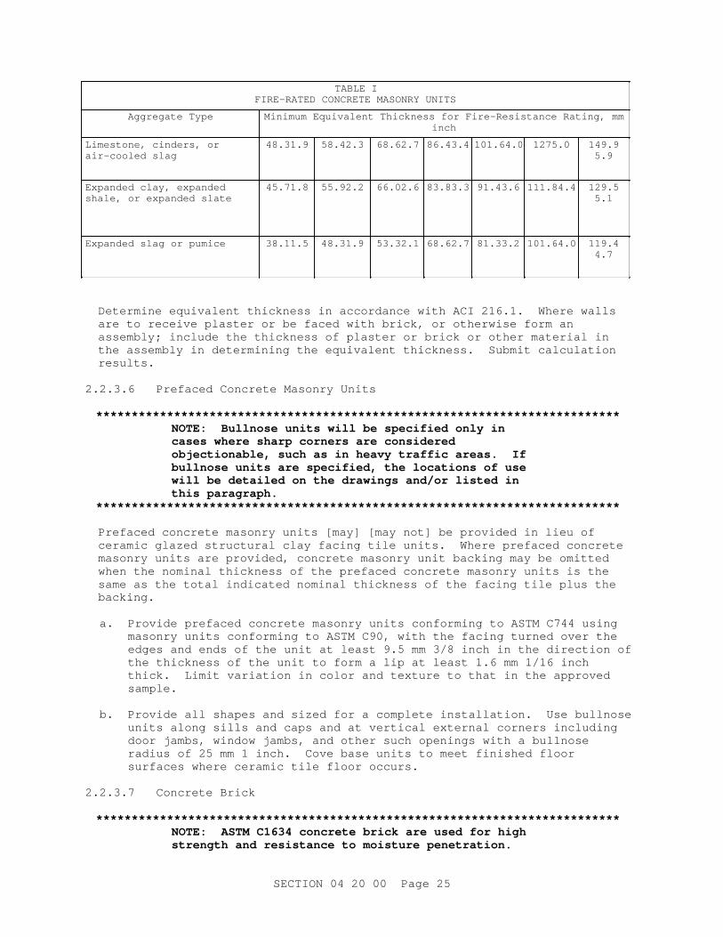
TABLE IFI RE- RATED CONCRETE MASONRY UNI TS
Aggr egat e Type Mi ni mum Equi val ent Thi ckness f or Fi r e- Resi st ance Rat i ng, mminch
Li mest one, c i nder s, or ai r - cool ed sl ag
48.31.9 58.42.3 68.62.7 86.43.4 101.64.0 1275.0 149.95.9
Expanded cl ay, expanded shal e, or expanded sl at e
45.71.8 55.92.2 66.02.6 83.83.3 91.43.6 111.84.4 129.55.1
Expanded sl ag or pumi ce 38.11.5 48.31.9 53.32.1 68.62.7 81.33.2 101.64.0 119.44.7
Det er mi ne equi val ent t hi ckness i n accor dance wi t h ACI 216. 1. Wher e wal l s ar e t o r ecei ve pl ast er or be f aced wi t h br i ck, or ot her wi se f or m an assembl y; i ncl ude t he t hi ckness of pl ast er or br i ck or ot her mat er i al i n t he assembl y i n det er mi ni ng t he equi val ent t hi ckness. Submi t cal cul at i on results.
2. 2. 3. 6 Pr ef aced Concr et e Masonr y Uni t s
**************************************************************************NOTE: Bul l nose uni t s wi l l be speci f i ed onl y i n cases wher e shar p cor ner s ar e consi der ed obj ect i onabl e, such as i n heavy t r af f i c ar eas. I f bul l nose uni t s ar e speci f i ed, t he l ocat i ons of use wi l l be det ai l ed on t he dr awi ngs and/ or l i s t ed i n t hi s par agr aph.
**************************************************************************
Pr ef aced concr et e masonr y uni t s [ may] [ may not ] be pr ovi ded i n l i eu of cer ami c gl azed st r uct ur al c l ay f aci ng t i l e uni t s. Wher e pr ef aced concr et e masonr y uni t s ar e pr ovi ded, concr et e masonr y uni t backi ng may be omi t t ed when t he nomi nal t hi ckness of t he pr ef aced concr et e masonr y uni t s i s t he same as t he t ot al i ndi cat ed nomi nal t hi ckness of t he f aci ng t i l e pl us t he backing.
a. Pr ovi de pr ef aced concr et e masonr y uni t s conf or mi ng t o ASTM C744 usi ng masonr y uni t s conf or mi ng t o ASTM C90, wi t h t he f aci ng t ur ned over t he edges and ends of t he uni t at l east 9. 5 mm 3/ 8 i nch i n t he di r ect i on of t he t hi ckness of t he uni t t o f or m a l i p at l east 1. 6 mm 1/ 16 i nch t hi ck. Li mi t var i at i on i n col or and t ext ur e t o t hat i n t he appr oved sample.
b. Pr ovi de al l shapes and si zed f or a compl et e i nst al l at i on. Use bul l nose uni t s al ong si l l s and caps and at ver t i cal ext er nal cor ner s i ncl udi ng door j ambs, wi ndow j ambs, and ot her such openi ngs wi t h a bul l nose r adi us of 25 mm 1 i nch. Cove base uni t s t o meet f i ni shed f l oor sur f aces wher e cer ami c t i l e f l oor occur s.
2. 2. 3. 7 Concr et e Br i ck
**************************************************************************NOTE: ASTM C1634 concr et e br i ck ar e used f or hi gh st r engt h and r esi st ance t o moi st ur e penet r at i on.
SECTI ON 04 20 00 Page 25

Spl i t f ace br i ck ( sol i d concr et e f aci ng uni t s) , wher e r equi r ed by desi gn, shoul d be added t o t hi s par agr aph. A par t i cul ar col or and t ext ur e may be speci f i ed when l ocal l y avai l abl e and compet i t i vel y pr i ced. Si zes may be speci f i ed f or br i ck or spl i t f ace br i ck wher e r equi r ed by t he desi gn.
ASTM C55 concr et e br i ck ar e used f or l esser st r engt h and moi st ur e r esi st ance, and wher e appear ance i s of l ow i mpor t ance.
ASTM C73 sand- l i me br i ck may be used on t he i nt er i or or ext er i or . Wher e l i mi t ed t o i nt er i or use, Gr ade MSW may be speci f i ed as an opt i on t o Gr ade SW.
**************************************************************************
2. 2. 3. 7. 1 Common Concr et e Br i ck
Pr ovi de common concr et e br i ck conf or mi ng t o ASTM C55. Common concr et e br i ck may be used wher e necessar y f or f i l l i ng out i n concr et e masonr y uni t construction.
2. 2. 3. 7. 2 Concr et e Br i ck f or Faci ng
Pr ovi de concr et e br i ck f or exposed appl i cat i ons t hat conf or ms t o ASTM C1634. Submi t sampl es as speci f i ed.
2. 2. 3. 7. 3 Sand- Li me Br i ck
Pr ovi de cal c i um- si l i cat e ( sand- l i me) t hat conf or ms t o ASTM C73, Gr ade SW, appr oxi mat el y 92 mm t hi ck, 57 mm hi gh, 194 mm l ong 3- 5/ 8 i nches t hi ck, 2- 1/ 4 i nches hi gh, and 8 i nches l ong or modul ar , wi t h smoot h sur f aces and nat ur al col or .
2. 2. 4 Pr ecast Concr et e Uni t s
**************************************************************************NOTE: Ar chi t ect ur al Cast St one i s a r ef i ned ar chi t ect ur al concr et e bui l di ng uni t manuf act ur ed t o s i mul at e nat ur al cut st one and may be speci f i ed i n l i eu of pr ecast concr et e. I t exceeds mi ni mum r equi r ement s f or compr essi ve st r engt h and weat her i ng qual i t i es essent i al f or common i nst al l at i ons and may be a sui t abl e r epl acement f or nat ur al cut l i mest one, br ownst one, sandst one, bl uest one, gr ani t e, s l at e, keyst one, t r aver t i ne, and ot her nat ur al bui l di ng st ones. When speci f i ed f or use i n c l i mat es t hat exper i ence f r eeze- t haw, i t s dur abi l i t y can be demonst r at ed by f i el d per f or mance of s i mi l ar pr oduct s i n s i mi l ar exposur es f or many year s, or i t can be t est ed by a modi f i ed ver si on of ASTM C666, Pr ocedur e A, per Cast St one I nst i t ut e l i t er at ur e. Cast st one masonr y pr oduct s may be used as ar chi t ect ur al f eat ur e, t r i m, and or nament , f aci ng or ot her non- st r uct ur al use i n bui l di ngs and ot her structures.
**************************************************************************
SECTI ON 04 20 00 Page 26
2. 2. 4. 1 General
a. Pr ovi de pr ecast concr et e t r i m, l i nt el s, copi ngs, spl ashbl ocks and si l l s t hat ar e f act or y- made uni t s i n a pl ant r egul ar l y engaged i n pr oduci ng pr ecast concr et e uni t s. Unl ess ot her wi se i ndi cat ed, pr ovi de pr ecast concr et e wi t h mi ni mum [ 28] [ 20] MPa [ 4, 000] [ 3000] psi compr essi ve st r engt h, conf or mi ng t o Sect i on [ 03 30 00. 00 10 CAST- I N- PLACE CONCRETE] [ 03 30 00 CAST- I N- PLACE CONCRETE] usi ng 13 mm 1/ 2 i nch t o No. 4 nomi nal - s i ze coar se aggr egat e, and wi t h r ei nf or cement r equi r ed f or handl i ng of t he uni t s. Mai nt ai n mi ni mum cl ear ance of 19 mm 3/ 4 i nch bet ween r ei nf or cement and f aces of uni t s.
b. Unl ess pr ecast - concr et e i t ems have been subj ect ed dur i ng manuf act ur e t o sat ur at ed- st eam pr essur e of at l east 827 kPa 120 psi f or at l east 5 hour s, ei t her damp- cur e f or 24 hour s or st eam- cur e and t hen age under cover f or 28 days or l onger . I n pr ecast concr et e member s wei ghi ng over 35 kg 80 pounds pr ovi de bui l t - i n l oops of gal vani zed wi r e or ot her appr oved pr ovi s i ons f or l i f t i ng and anchor i ng.
c. Fabr i cat e uni t s wi t h beds and j oi nt s at r i ght angl es t o t he f ace, wi t h shar p t r ue ar i ses and wi t h dr i p gr ooves on t he under si de wher e uni t s over hang wal l s. For m exposed- t o- v i ew sur f aces f r ee of sur f ace voi ds, spal l s, cr acks, and chi pped or br oken edges and wi t h uni f or m appear ance and col or . Unl ess ot her wi se speci f i ed, pr ovi de uni t s wi t h a smoot h dense f i ni sh.
d. Pr i or t o i nst al l at i on, wet and i nspect each uni t f or cr azi ng. I t ems
showi ng evi dence of dust i ng, spal l i ng, cr azi ng, or havi ng sur f aces t r eat ed wi t h a pr ot ect i ve coat i ng wi l l be r ej ect ed.
e. Submi t speci f i ed f act or y cer t i f i cat es. [
f . Pr ovi de ar chi t ect ur al cast st one masonr y t r i m, copi ngs, heads, and si l l s t hat ar e manuf act ur ed i n a pl ant by a pr oducer r egul ar l y engaged i n pr oduci ng cast st one. Pr ovi de cast st one uni t s t hat compl y wi t h ASTM C1364. Submi t t est r epor t s and t hr ee exempl ar s of t he same cast st one pr oduct i nst al l ed i n s i mi l ar pr oj ect s i n s i mi l ar c l i mat i c conditions. ]
2. 2. 4. 2 Pr ecast Concr et e Li nt el s
**************************************************************************NOTE: I nser t st r engt h of concr et e; pr ecast l i nt el s usual l y r ange f r om 17 t o 25 MPa 2500 t o 3500 psi . Al t er nat i vel y, r ei nf or ced masonr y l i nt el s may be desi gned i n conf or mance wi t h TMS MSJC.
**************************************************************************
Pr ovi de pr ecast concr et e l i nt el s, unl ess ot her wi se shown, of a t hi ckness equal t o t he wal l and r ei nf or ced wi t h mi ni mum t wo No. 4 bar s f or t he f ul l l engt h. Pr ovi de t op and bot t om bar s f or l i nt el s over 914 mm 36 i nches i n l engt h. Pr ovi de at l east 200 mm 8 i nches bear i ng at each end. Label t he t op of l i nt el s and cl ear l y mar k each l i nt el t o show l ocat i on i n t he st r uct ur e. Desi gn r ei nf or ced l i nt el s i n conf or mance wi t h ACI 318M ACI 318 f or f l exur al and shear st r engt h, usi ng concr et e wi t h a mi ni mum 28 day compr essi ve st r engt h of [ _____] MPa psi . Li mi t l i nt el def l ect i on due t o dead pl us l i ve l oad t o L/ 600 or 7. 6 mm 0. 3 i nches.
SECTI ON 04 20 00 Page 27

2. 2. 4. 3 Pr ecast Concr et e Si l l s and Copi ngs
**************************************************************************NOTE: Lug si l l s , whi ch ar e l onger t han t he wi ndow openi ng, el i mi nat e t he vul ner abl e head j oi nt t hat occur s at t he end of s l i p s i l l s , whi ch ar e t he same l engt h as t he wi ndow openi ng.
**************************************************************************
Cast s i l l s and copi ngs washes. For wi ndows havi ng mul l i ons, cast s i l l s i n sect i ons wi t h head j oi nt s at mul l i ons and a 6 mm 1/ 4 i nch al l owance f or mor t ar j oi nt s. Roughen t he ends of s i l l s , except a 19 mm 3/ 4 i nch wi de mar gi n at exposed sur f aces, f or bond. Pr ovi de r ounded nosi ngs on t r eads of door s i l l s . [ Rei nf or ce s i l l s wi t h not l ess t han t wo No. 15 No. 4 bar s. ]
2. 2. 5 DI MENSI ON STONE UNI TS
**************************************************************************NOTE: The st one speci f i ed her ei n i s f or st r uct ur es r equi r i ng a l i mi t ed quant i t y of cut st one. Wher e pr evi ous exper i ence i ndi cat es di f f i cul t y i n obt ai ni ng pr ecast concr et e t r i m of t he speci f i ed qual i t y , st one may be speci f i ed as a Cont r act or ' s option.
**************************************************************************
Pr ovi de di mensi on st one f or t r i m, s i l l s , l i nt el s, and copi ngs cut t o t he desi gn shown and conf or mi ng t o:
Limestone ASTM C586 St andar d buf f col or wi t h a smoot h machi ne f i ni sh f r ee f r om t ool mar ks
Sandstone ASTM C616/ C616M St andar d gr ade, buf f , gr ay, or buf f br own, wi t h a smoot h f i ni sh f r ee f r om cl ay pi t s and t ool mar ks
Granite ASTM C616/ C615M Commer ci al gr ade of medi um or moder at el y coar se gr ai n, wi t h a l i ght or medi um gr ay or l i ght pi nk color
Pr ovi de a smoot h machi ne f i ni sh on washes, 4- cut f i ni sh on t r eads, and 6- cut or equi val ent machi ne f i ni sh on ot her exposed sur f aces. Except when suppor t ed by a st eel member , pr ovi de l i nt el s 100 mm 4 i nches or mor e i n t hi ckness f r om f ace t o back edge and of t he dept h r equi r ed t o suppor t t he masonr y over t he openi ng. Fabr i cat e st one wi t h beds and j oi nt s at r i ght angl es t o t he f ace, and wi t h shar p, t r ue ar i ses. Pr ovi de copi ngs and si l l s wi t h washes, and wher e over hangi ng t he wal l s, wi t h dr i ps cut on t he under si de. Submi t sampl es as speci f i ed.
2. 3 EQUIPMENT
**************************************************************************NOTE: The r equi r ement f or spar e v i br at or may be del et ed on smal l pr oj ect s.
**************************************************************************
SECTI ON 04 20 00 Page 28
2. 3. 1 Vibrators
Mai nt ai n at l east one spar e v i br at or on s i t e at al l t i mes.
2. 3. 2 Gr out Pumps
Pumpi ng t hr ough al umi num t ubes i s not per mi t t ed.
2. 4 MATERIALS
2. 4. 1 Mor t ar Mat er i al s
**************************************************************************NOTE: Ref er t o ASTM C270 f or speci f y i ng mor t ar , whi ch al l ows mor t ar t o be speci f i ed by pr opor t i ons ( ASTM C270 Tabl e 1) or pr oper t i es ( ASTM C270 Tabl e 2) but not bot h. Accept abl e cement i t i ous mat er i al s ar e l i s t ed i n t he st andar d, t hough not al l ar e appr opr i at e f or al l appl i cat i ons. For i nst ance, some cement s ar e used f or hi gh ear l y st r engt h or f or sul f at e r esi st ance. See Tabl e Hydr aul i c Cement s f or Masonr y Mor t ar bel ow f or compar abl e desi gnat i ons bet ween di f f er ent cement speci f i cat i ons. Al so, ASTM C270 Appendi x X1 cont ai ns gui dance on sel ect i on and use of mor t ar f or uni t masonr y by l ocat i on ( ext er i or , i nt er i or , above gr ade, bel ow gr ade) and bui l di ng segment t ype ( wal l , par t i t i on, f oundat i on, etc.).
Mor t ar t hat compl i es wi t h ASTM C1714 f or Uni t Masonr y, meet s t he r equi r ement s of ASTM C270. These mor t ar s ar e pr ebl ended dr y i n a f act or y and del i ver ed t o t he j ob- si t e i n packages ( bags or s i l os or t r ucks) .
A good r ul e of t humb i s t o speci f y t he weakest mor t ar t hat wi l l per f or m adequat el y, not t he st r ongest . I n accor dance wi t h TMS MSJC, mor t ar i n masonr y el ement s t hat ar e par t of t he sei smi c f or ce- r esi st i ng syst em i n Sei smi c Desi gn Cat egor y D or hi gher must be Type S or Type M, and must use por t l and cement / l i me or mor t ar cement as t hei r cement i t i ous mat er i al ( masonr y cement i s not per mi t t ed) . Ther ef or e, t hese masonr y member s must be i ndi cat ed on t he Dr awi ngs. Type O mor t ar shoul d not be used i n new const r uct i on.
Labor at or y t est i ng of mor t ar i s onl y r equi r ed f or accept ance of mor t ar mi xes under t he pr oper t y speci f i cat i ons of ASTM C270. Fi el d t est i ng of mor t ar s, conduct ed under ASTM C780, i s used t o ver i f y consi st ency of mat er i al s and pr ocedur es, not mor t ar st r engt h. Whi l e f i el d t est i ng of mor t ar st r engt h i s not r ecommended, i t can pr ovi de i nf or mat i on about degr ee of qual i t y cont r ol exer ci sed dur i ng mor t ar pr oduct i on at t he const r uct i on s i t e i f compar ed t o pr econst r uct i on t est val ues. However , compr essi ve t est r esul t s f or mor t ar ar e eval uat ed af t er 28 days, so
SECTI ON 04 20 00 Page 29
mor t ar - aggr egat e r at i o t est i ng per ASTM C780, whi ch can t ake as l i t t l e as f our hour s, may be mor e usef ul f or eval uat i ng mor t ar consi st ency. Obser vat i on of mor t ar mi xi ng, t o ver i f y pr oper pr opor t i oni ng, i s t he best eval uat or of mor t ar consi st ency and qual i t y .
For whi t e mor t ar , speci f y whi t e cement . For col or ed mor t ar , whi t e cement or gr ay cement may be speci f i ed, dependi ng on t he desi r ed col or . Col or i s achi eved by addi ng pi gment s at t he t i me of mi x i ng or by sel ect i ng pr ebl ended col or ed cement i t i ous mat er i al s or pr ebl ended col or ed mor t ar mat er i al s. Excessi ve use of pi gment s t o achi eve mor t ar col or may r educe bot h compr essi ve and t ensi l e st r engt hs of masonr y. Conf or mance t o maxi mum per cent ages i ndi cat ed wi l l l i mi t l oss of st r engt h t o accept abl e amount s. Due t o t hei r f i ne par t i c l e s i ze, col or i ng pi gment s i ncr ease wat er demand.
Wher e ef f l or escence i s a concer n, t echni ques f or mi ni mi zi ng i t s occur r ence ar e descr i bed i n ASTM C1400. Techni ques i ncl ude: mi ni mi zi ng wat er penet r at i on i nt o t he wal l , such as by use of over hangs; f aci l i t at i ng dr ai nage of wat er i n t he wal l ; avoi di ng cont act bet ween di ssi mi l ar masonr y uni t s; and mi ni mi zi ng pot ent i al ef f l or escence compounds i n t he wal l mat er i al s.
**************************************************************************
2. 4. 1. 1 Cement i t i ous Mat er i al s
**************************************************************************NOTE: See Sect i on 01 33 29 SUSTAI NABI LI TY REPORTI NG and i ncl ude addi t i ve opt i ons unl ess desi gner det er mi nes t hat j ust i f i cat i on f or non- use exi st s. Suppl ement ar y cement i t i ous mat er i al s ar e of t en i ncl uded as i ngr edi ent s i n mor t ar t hat conf or ms t o ASTM C595 bl ended cement s or ASTM C1157 hydr aul i c cement s. See " Hydr aul i c Cement s f or Masonr y Mor t ar " t abl e bel ow f or di f f er ent ASTM C150, C595, and C1157 cement s t hat ar e al l owed i n masonr y mor t ar by ASTM C270. For exampl e, hi gh- ear l y st r engt h cement may be used when const r uct i ng i n col d weat her . Cont r act or s sel ect cement i t i ous mat er i al s based on per f or mance, avai l abi l i t y , and f ami l i ar i t y , and t he Cont r act i ng Of f i cer shoul d be awar e t hat mor e t han one cement desi gnat i on can sat i sf y t he same need, such as hi gh ear l y st r engt h.
SECTI ON 04 20 00 Page 30

Hydr aul i c Cement s f or Masonr y Mor t ar
Cement Speci f i cat i on+
ASTM C150 por t l andcements
ASTM C595 bl ended
hydr aul i c cement s*ASTM C595 bl ended
hydr aul i c cement s*
Gener al Pur pose I ILIS(<70)
IPIT(S<70)
GU
Moder at e heat of hydration
II(MH) IL(MH)IS(<70)(MH)
IP(MH)IT(S<70)(MH)
MH
Hi gh ear l y st r engt h III - HE
Low heat of hydration
IV IL(LH)IS(<70)(LH)
IP(LH)IT(S<70)(LH)
LH
Moder at e sul f at e resistance
I I , I I ( MH) IS(<70)(MS)IP(MS)
IT(S<70)(MS) **
MS
Hi gh sul f at e resistance
V IS(<70)(HS)IP(HS)
IT(S<70)(HS) **
HS
* Type I T( S<70) cement s ar e t er nar y bl ended cement s wi t h l ess t han 70 per cent by mass sl ag cement cont ent . For t hi s t abl e, t hi s i ncl udes t er nar y bl ended cement s wi t h pozzol ans and l i mest one ( no sl ag cement ) as t he non- por t l and i ngr edi ent s.
* * Type I T cement s wi t h bet ween 5 and 15 per cent ( by mass) l i mest one cont ent ar e not per mi t t ed t o be used i n sul f at e exposur e appl i cat i ons, pendi ng r esul t s of research.
+Ai r - ent r ai ned count er par t s f or cement s l i s t ed ar e al so al l owed i n masonr y mor t ar per t he pr opor t i oni ng r equi r ement s of ASTM C270.
**************************************************************************
Pr ovi de cement i t i ous mat er i al s t hat conf or m t o t hose per mi t t ed by ASTM C270.
2. 4. 1. 2 Hydr at ed Li me and Al t er nat es
**************************************************************************NOTE: Hi gher l i me cont ent i ncr eases wor kabi l i t y and wat er r et ent i v i t y. Al l owabl e l i me mat er i al s i ncl ude ASTM C207 hydr at ed l i me and ASTM C5 qui ckl i me.
**************************************************************************
Pr ovi de l i me t hat conf or ms t o one of t he mat er i al s per mi t t ed by ASTM C207 f or use i n combi nat i on wi t h por t l and cement , hydr aul i c cement , and bl ended hydr aul i c cement . Do not use l i me i n combi nat i on wi t h masonr y cement or mor t ar cement .
SECTI ON 04 20 00 Page 31

2. 4. 1. 3 Col or ed Mor t ar
**************************************************************************NOTE: I ndi cat e on t he dr awi ngs l ocat i ons of col or ed mor t ar . Maxi mum al l owabl e pi gment dosages ar e based on ASTM C270 Appendi x X1 and TMS MSJC Ar t i c l e 2. 6 A. 2. When pi gment s t hat compl y wi t h ASTM C979 ar e used at maxi mum per mi t t ed dosage, 28- day st r engt h of col or ed mor t ar i s not l ess t han 90 per cent of t he cont r ol mi x and wat er - cement i t i ous mat er i al s r at i o i s no mor e t han 110 per cent of t he cont r ol mi x.
**************************************************************************
Use mor t ar pi gment t hat conf or ms t o ASTM C979/ C979M. Add pi gment t o mor t ar t o pr oduce a uni f or m col or mat chi ng [ _____] . Fur ni sh pi gment s i n accur at el y pr e- measur ed and packaged uni t s t hat can be added t o a measur ed amount of cement i t i ous mat er i al s or suppl y pi gment s v i a pr ebl ended cement i t i ous mat er i al s or dr y mor t ar mi x.
a. I n masonr y cement or mor t ar cement , do not exceed [ 5] [ _____] per cent of cement wei ght f or mi ner al oxi de pi gment ; do not exceed [ 1] [ _____] per cent of cement wei ght f or car bon bl ack pi gment .
b. I n cement - l i me mor t ar mi x, do not exceed [ 10] [ _____] per cent of cement i t i ous mat er i al s ' wei ght f or mi ner al oxi de pi gment ; do not exceed [ 2] [ _____] per cent of cement i t i ous mat er i al s ' wei ght f or car bon bl ack pigment.
2. 4. 1. 4 Admi xt ur es f or Masonr y Mor t ar
**************************************************************************NOTE: Admi xt ur es can i mpr ove per f or mance of mor t ar and ar e speci f i ed f or benef i c i al pur poses, but pot ent i al negat i ve s i de ef f ect s i ncl ude an i ncr eased r i sk of ef f l or escence, r educed st r engt h of mor t ar , and cor r osi on of embedded st eel i t ems. Admi xt ur es t hat compl y wi t h ASTM C1384 have l i mi t ed negat i ve s i de ef f ect s and meet t he mi ni mum r equi r ement s f or i mpr ovement i n per f or mance of t he desi r ed at t r i but e, such as r at e of set , wat er - r epel l ency, or bond.
Shower s, k i t chens, and si ngl e- wyt he concr et e masonr y uni t ext er i or wal l s shoul d be bui l t wi t h concr et e bl ock cont ai ni ng i nt egr al wat er - r epel l ent admi xt ur e. When wat er r epel l ent s ar e used i n concr et e masonr y, t he mor t ar shoul d cont ai n a compat i bl e wat er - r epel l ent admi xt ur e. A compl ement ar y mat er i al f r om t he same manuf act ur er and of t he same br and i s desi gned t o be compat i bl e wi t h t he bl ock admi xt ur e.
**************************************************************************
I n col d weat her , use a non- chl or i de based accel er at i ng admi xt ur e t hat conf or ms t o ASTM C1384, unl ess Type I I I por t l and cement i s used i n t he mortar.
I n shower s and k i t chens, use mor t ar t hat cont ai ns a wat er - r epel l ent admi xt ur e t hat conf or ms t o ASTM C1384. Pr ovi de a wat er - r epel l ent admi xt ur e, conf or mi ng t o ASTM C1384 and of t he same br and and manuf act ur er
SECTI ON 04 20 00 Page 32

as t he bl ock' s i nt egr al wat er - r epel l ent , i n t he mor t ar used t o pl ace concr et e masonr y uni t s t hat have an i nt egr al wat er - r epel l ent admi xt ur e.
2. 4. 1. 5 Aggr egat e and Wat er
Pr ovi de aggr egat e ( sand) and wat er t hat conf or m t o mat er i al s per mi t t ed by ASTM C270.
2. 4. 2 Gr out and Ready- Mi x Gr out Mat er i al s
**************************************************************************NOTE: Accept abl e cement s f or masonr y gr out ar e l i s t ed i n ASTM C476 and ar e summar i zed i n Tabl e " Hydr aul i c Cement s f or Masonr y Gr out Const r uct i on i n ASTM C476" bel ow. Check t he l ocal avai l abi l i t y of speci f i c cement s as al l cement s ar e not avai l abl e ever ywher e. Per ASTM C476, ot her accept abl e cement i t i ous mat er i al s f or masonr y gr out ar e f l y ash and sl ag and smal l quant i t i es of l i me. Not e t hat masonr y cement and mor t ar cement ar e not per mi t t ed t o be used i n gr out . When hi gh- ear l y st r engt h cement , such as Type I I I Por t l and cement , i s used f or col d weat her const r uct i on, t he pr ot ect i on per i od f or gr out ed masonr y may be r educed.
Hydr aul i c Cement s f or Masonr y Gr out Const r uct i on i n ASTM C476
Cement specification*
Gener al Pur pose Hi gh ear l ystrength
Moderatesulfate
resistance
Hi gh sul f at eresistance
ASTM C150 por t l and cement s
I III II -
ASTM C595 blended hydraulic cements**
IS(<70)IP
- IS(<70)(MS) -
ASTM C1157 hydraulic cements
GU HE MS HS
* Ai r - ent r ai ned count er par t s f or t hese cement s l i st ed ar e al so al l owed i n masonr y gr out . However , use of ai r - ent r ai nment i s not r ecommended when t he gr out wi l l be used t o bond r ei nf or cement t o t he masonr y uni t s.
**
**************************************************************************
2. 4. 2. 1 Cement i t i ous Mat er i al s f or Gr out
Pr ovi de cement i t i ous mat er i al s t hat conf or m t o t hose per mi t t ed by ASTM C476.
2. 4. 2. 2 Admi xt ur es f or Gr out
**************************************************************************NOTE: Admi xt ur es, i ncl udi ng ai r ent r ai nment , may cont r i but e t o ef f l or escence and may adver sel y af f ect
SECTI ON 04 20 00 Page 33

t he st r engt h of t he mi x or t he pr ot ect i on of embedded st eel i t ems. Admi xt ur es t hat compl y wi t h C494/ C494M Type F or G wat er r educi ng admi xt ur es and vi scosi t y- modi f y i ng admi xt ur es ar e per mi t t ed, but ot her s, such as i nt egr al wat er pr oof i ng compounds, accel er at or s, and ot her s, r equi r e appr oval f r om purchaser.
When concr et e masonr y and cl ay br i ck uni t s ar e hi ghl y absor bent , a gr out i ng ai d admi xt ur e may be desi r abl e t o r educe ear l y wat er l oss, pr omot e bondi ng, and pr oduce sl i ght expansi on t o hel p ensur e compl et e f i l l i ng of cavi t i es.
**************************************************************************
Wat er - r educi ng admi xt ur es t hat conf or m t o ASTM C494/ C494M Type F or G and vi scosi t y- modi f y i ng admi xt ur es t hat conf or m t o ASTM C494/ C494M Type S ar e per mi t t ed f or use i n gr out . Ot her admi xt ur es r equi r e appr oval by t he Cont r act i ng Of f i cer .
I n col d weat her , a non- chl or i de based accel er at i ng admi xt ur e may be used subj ect t o appr oval by t he Cont r act i ng Of f i cer ; use accel er at i ng admi xt ur e t hat i s non- cor r osi ve and conf or ms t o ASTM C494/ C494M, Type C.
2. 4. 2. 3 Aggr egat e and Wat er
Pr ovi de f i ne and coar se aggr egat es and wat er t hat conf or m t o mat er i al s per mi t t ed by ASTM C476.
2. 5 MORTAR AND GROUT MI XES
**************************************************************************NOTE: Some pr ebl ended mor t ar s may r equi r e speci al mi x i ng pr ocedur es. I f so, f ol l ow manuf act ur er s publ i shed r ecommendat i ons.
I ndi cat e sei smi c f or ce- r esi st i ng masonr y el ement s on t he Dr awi ngs.
**************************************************************************
2. 5. 1 Mor t ar Mi x
a. Pr ovi de mor t ar Type [ N] [ S] [ M] unl ess speci f i ed ot her wi se her ei n. [ Do not use masonr y cement i n t he mor t ar . ] [ Do not use ai r - ent r ai nment i n t he mor t ar . ]
b. Use ASTM C270 Type [ S] [ M] cement - l i me mor t ar or mor t ar cement mor t ar f or sei smi c- f or ce- r esi st i ng el ement s i ndi cat ed. [
c. Pr ovi de mor t ar t hat conf or ms t o ASTM C270. Use Type [ M] [ S] [ N] mor t ar [ f or f oundat i on wal l s] [ , basement wal l s, ] [ and i n pi er s] . ][
d. Pr ovi de Type N or S mor t ar f or non- l oad- bear i ng, non- shear - wal l i nt er i or masonr y. ][
e. Pr ovi de appr oved commer ci al f i r e c l ay mor t ar or r ef r act or y cement ( cal c i um- al umi nat e) mor t ar f or f i r e br i ck and f l ue l i ner s. ]
[ c] [ d] [ e] [ f ] . For f i el d- bat ched mor t ar , measur e component mat er i al s by
SECTI ON 04 20 00 Page 34

vol ume. Use measur i ng boxes f or mat er i al s t hat do not come i n packages, such as sand, f or consi st ent bat chi ng. Mi x cement i t i ous mat er i al s and aggr egat es bet ween 3 and 5 mi nut es i n a mechani cal bat ch mi xer wi t h a suf f i c i ent amount of wat er t o pr oduce a wor kabl e consi st ency. Do not hand mi x mor t ar unl ess appr oved by t he Cont r act i ng Of f i cer . Mai nt ai n wor kabi l i t y of mor t ar by r emi xi ng or r et emper i ng. Di scar d mor t ar t hat has begun t o st i f f en or i s not used wi t hi n 2- 1/ 2 hour s af t er i ni t i al mi x i ng.
[ d] [ e] [ f ] [ g] . For pr ebl ended mor t ar , f ol l ow manuf act ur er ' s mi xi ng instructions.
2. 5. 2 Gr out and Ready Mi x Gr out Mi x
**************************************************************************NOTE: Gr out st r engt h must be at l east as gr eat as t he speci f i ed compr essi ve st r engt h of masonr y ( f ' m) but not l ess t han 14 MPa 2000 psi at 28 days. Revi se speci f i cat i on when gr out compr essi ve st r engt h i s r equi r ed t o be i n excess of 14 MPa 2000 psi .
Choi ce of f i ne or coar se gr out depends on wi dt h of gr out space and pour hei ght ; t abul at ed l i mi t at i on can be f ound i n TMS MSJC. The Cont r act or usual l y has t he opt i on t o sel ect gr out t ype, but under speci al c i r cumst ances, t he Engi neer - of - Recor d may want t o def i ne gr out t ype.
**************************************************************************
Use gr out t hat conf or ms t o ASTM C476, [ f i ne] [ coar se] . Use convent i onal gr out wi t h a s l ump bet ween 203 and [ 279] mm 8 and [ 11] i nches. Use sel f - consol i dat i ng gr out wi t h s l ump f l ow of 610 t o 762 mm 24 t o 30 i nches and a v i sual st abi l i t y i ndex ( VSI ) not gr eat er t han 1. Pr ovi de mi ni mum gr out st r engt h of [ 14] [ _____] MPa [ 2000] [ _____] ps i i n 28 days, as t est ed i n accor dance wi t h ASTM C1019. Do not change pr opor t i ons and do not use mat er i al s wi t h di f f er ent physi cal or chemi cal char act er i st i cs i n gr out f or t he wor k unl ess addi t i onal evi dence i s f ur ni shed t hat gr out meet s t he speci f i ed r equi r ement s. Use r eady- mi xed gr out t hat conf or ms t o ASTM C476.
2. 6 ACCESSORIES
2. 6. 1 Gr out Bar r i er s
Gr out bar r i er s f or ver t i cal cor es t hat consi st of f i ne mesh wi r e, f i ber gl ass, or expanded met al .
2. 6. 2 Anchor s, Ti es, and Bar Posi t i oner s
**************************************************************************NOTE: By def i ni t i on, t i es ar e connect i ons bet ween masonr y wyt hes, anchor s connect masonr y t o t he st r uct ur e and connect veneer t o i t s backi ng, and f ast ener s ar e f or at t achment of non- masonr y i t ems t o masonr y. The anchor s and t i es speci f i ed i n t hi s par agr aph ar e pr i mar i l y used t o l at er al l y t i e masonr y veneer t o backup el ement s. Anchor s and t i es not i ncor por at ed i n t he desi gn shoul d be del et ed. I f speci al anchor s or t i es ar e r equi r ed by t he desi gn, t hey wi l l be speci f i ed t o meet t he necessar y
SECTI ON 04 20 00 Page 35

r equi r ement s. St andar d anchor s and t i es can be used i n cavi t i es up t o 114 mm 4. 5 i nches wi de.
The r equi r ed mi ni mum zi nc coat i ng t hi cknesses f or wi r e t i es, anchor s, and j oi nt r ei nf or cement ar e shown i n t he f ol l owi ng t abl e and ar e based on exposure:
Exposure Finish Wt . of Coat i ng i n Gr amPer Sq. Met er Oz. Per Sq.
Foot
Joi nt r ei nf or cement , i nt er i or walls
ASTM A641/ A641M 31 0. 1
Wi r e t i es or anchor s ASTM A53/ A153M 458 1. 50
St eel pl at es and bar s ASTM A153/ A153M Cl ass B or ASTM A123/ A123M as appl i cabl e t o s i ze and f or m
Joi nt r ei nf or cement i n ext er i or wal l s or i nt er i or wal l s exposed t o moi st envi r onment s ( e. g. nat at or i a and f ood pr ocessi ng)
ASTM A153/ A153M 458 1. 50
Sheet met al t i es or anchor s i n masonr y exposed t o weat her
ASTM A153/ A153MCl ass B
458 1. 50
Sheet met al t i es or anchor s ASTM A653/ A653M ( Cl ass G60)
180 . 60
**************************************************************************
2. 6. 2. 1 General
a. Fabr i cat e anchor s and t i es wi t hout dr i ps or cr i mps. Si ze anchor s and t i es t o pr ovi de a mi ni mum of 16 mm 5/ 8 i nch mor t ar cover f r om each f ace of masonr y.
b. Fabr i cat e st eel wi r e anchor s and t i es shal l f r om wi r e conf or mi ng t o
SECTI ON 04 20 00 Page 36
ASTM A1064/ A1064M and hot - di p gal vani ze i n accor dance wi t h ASTM A153/ A153M.
c. Fabr i cat e j oi nt r ei nf or cement i n conf or mance wi t h ASTM A951/ A951M. Hot di p gal vani ze j oi nt r ei nf or cement i n ext er i or wal l s and i n i nt er i or wal l s exposed t o moi st envi r onment i n conf or mance wi t h ASTM A153/ A153M. Gal vani ze j oi nt r ei nf or cement i n ot her i nt er i or wal l s i n conf or mance with ASTM A641/ A641M; coor di nat e wi t h par agr aph JOI NT REI NFORCEMENT below.
d. Fabr i cat e sheet met al anchor s and t i es i n conf or mance wi t h ASTM A1008/ A1008M. Hot di p gal vani ze sheet met al anchor s and t i es i n ext er i or wal l s and i n i nt er i or wal l s exposed t o moi st envi r onment i n compl i ance wi t h ASTM A153/ A153M Cl ass B. Gal vani ze sheet met al anchor s and t i es i n ot her i nt er i or wal l s i n compl i ance wi t h ASTM A653/ A653M, Coat i ng Desi gnat i on G60.
e. Submi t t wo anchor s, t i es and bar posi t i oner s of each t ype used, as samples.
2. 6. 2. 2 Wi r e Mesh Anchor s
**************************************************************************NOTE: Wi r e mesh anchor s wi l l onl y be used t o connect i nt er i or non- bear i ng wal l s t o ot her i nt er sect i ng i nt er i or non- bear i ng masonr y wal l s.
**************************************************************************
Pr ovi de wi r e mesh anchor s of 6 mm 1/ 4 i nch mesh gal vani zed har dwar e c l ot h, conf or mi ng t o ASTM A185/ A185M, wi t h l engt h not l ess t han 305 mm 12 i nches, at i nt er sect i ons of i nt er i or non- bear i ng masonr y wal l s.
2. 6. 2. 3 Wal l Ti es f or Mul t i - Wyt he Masonr y Const r uct i on
**************************************************************************NOTE: Wal l t i es wi l l be speci f i ed t o pr ovi de an opt i on t o t he t ypi cal l y used cont i nuous j oi nt r ei nf or cement t o anchor t he out er wyt he t o t he i nner wyt he of mul t i pl e wyt he masonr y const r uct i on. Ver t i cal spaci ng wi l l nor mal l y be 400 mm 16 i nches on cent er and hor i zont al spaci ng of t he uni t t i es wi l l nor mal l y be 600 mm 24 i nches on cent er .
Rect angul ar t i es may be used wi t h ei t her sol i d or hol l ow uni t s. The maxi mum wal l ar ea per r ect angul ar t i e of wi r e s i ze MW11 W1. 7 i s 0. 25 m2 2- 2/ 3 f t 2; when t he wi r e s i ze i s MW18 W2. 8 t he maxi mum wal l ar ea per t i e i s 0. 42 m2 4. 5 f t 2. Ther e ar e addi t i onal r equi r ement s f or wal l t i es based on how t he masonr y i s desi gned ( veneer or engi neer ed non- composi t e) , spaci ng, and sei smi c desi gn cat egor y of bui l di ngs wi t h veneer .
Adj ust abl e wal l t i es ar e nor mal l y used when const r uct i ng one wyt he i ndependent of t he ot her . The pr ef er r ed met hod of const r uct i on, however , i s t o br i ng t he wyt hes up t oget her . Del et e t he sent ences per t ai ni ng t o adj ust abl e t i es when t hey ar e not permitted.
SECTI ON 04 20 00 Page 37
**************************************************************************
Pr ovi de r ect angul ar - shaped wal l t i es, f abr i cat ed of hot - di pped gal vani zed [MW11W1. 7] [ MW18W2. 8] di amet er st eel wi r e. Pr ovi de r ect angul ar wal l t i es no l ess t han 100 mm 4 i nches wi de.
Pr ovi de adj ust abl e t ype wal l t i es, i f appr oved f or use, t hat consi st of t wo essent i al l y U- shaped el ement s f abr i cat ed of mi ni mum MW18 W2. 8 di amet er st eel wi r e or pi nt l e t ype t i es t hat ar e i nser t ed t o eyes of hor i zont al j oi nt r ei nf or cement , hot - di p gal vani zed. Pr ovi de adj ust abl e t i es wi t h doubl e pi nt l e l egs and al l ows a maxi mum of f set of 32 mm 1- 1/ 4 i nch bet ween each el ement of t he t i e and maxi mum di st ance bet ween connect i ng par t s no mor e t han 2 mm 1/ 16 i nch. For m t he pi nt l e and eye el ement s shal l be f or med so t hat bot h can be i n t he same pl ane. Wal l t i es may al so be of a cont i nuous t ype conf or mi ng t o par agr aph JOI NT REI NFORCEMENT.
2. 6. 2. 4 Dovet ai l Anchor s
Pr ovi de dovet ai l anchor s of 5 mm 3/ 16 i nch di amet er st eel wi r e, t r i angul ar shaped, and at t ached t o a 12 gauge 12 gauge or heavi er st eel dovet ai l sect i on. Use t hese anchor s t o connect t he ext er i or masonr y wyt he as i t passes over t he f ace of concr et e col umns, beams, or wal l s. Fi l l cel l s i mmedi at el y above and bel ow t hese anchor s unl ess sol i d uni t s ar e used. Fur ni sh dovet ai l s l ot s, whi ch ar e speci f i ed t o be i nst al l ed by ot her s, i n accor dance wi t h Sect i on [ 03 30 00. 00 10 CAST- I N- PLACE CONCRETE] [ 03 30 00 CAST- I N- PLACE CONCRETE] .
2. 6. 2. 5 Adj ust abl e Anchor s
**************************************************************************NOTE: Adj ust abl e anchor s wi l l be used t o anchor masonr y t o st r uct ur al st eel col umns or beams. Such anchor s wi l l be ei t her be det ai l ed on t he dr awi ngs, or t he capaci t y r equi r ement s wi l l be gi ven i n t he speci f i cat i on and t he cont r act or wi l l be r equi r ed t o submi t t est dat a t o ver i f y compl i ance. Sel ect t he appr opr i at e opt i on.
Adj ust abl e anchor s may al so be used t o connect veneer t o i t s backi ng. Adj ust abl e anchor s ar e r equi r ed when t he backi ng f or t he veneer i s st eel st ud f r ami ng or concr et e.
**************************************************************************
2. 6. 2. 5. 1 Anchor age t o St r uct ur al St eel
Pr ovi de [ hot - di p gal vani zed] [ st ai nl ess st eel ] adj ust abl e anchor s f or connect i ng masonr y wal l s t o t he st r uct ur al st eel f r ame [ as det ai l ed on t he dr awi ngs] [ t hat have [ _____] kg pounds capaci t y i n bot h t ensi on and compr essi on f or t he span i ndi cat ed when pl aced at [ _____] mm i nches on cent er ; submi t t est dat a t o ver i f y compl i ance] . [ Pr ovi de z i nc- r i ch pai nt f or t ouchi ng up pai nt af t er wel di ng gal vani zed anchor s t o st r uct ur al st eel . ]
2. 6. 2. 5. 2 Anchor age of Veneer t o Li ght Gauge St eel or Concr et e Backi ng
Use one of t he f ol l owi ng t ypes of adj ust abl e anchor s t o connect veneer t o l i ght gauge st eel or concr et e backi ng:
a. sheet met al at l east 22 mm 7/ 8 i nch wi de, 1. 5 mm 0. 06 i nch t hi ck, and
SECTI ON 04 20 00 Page 38
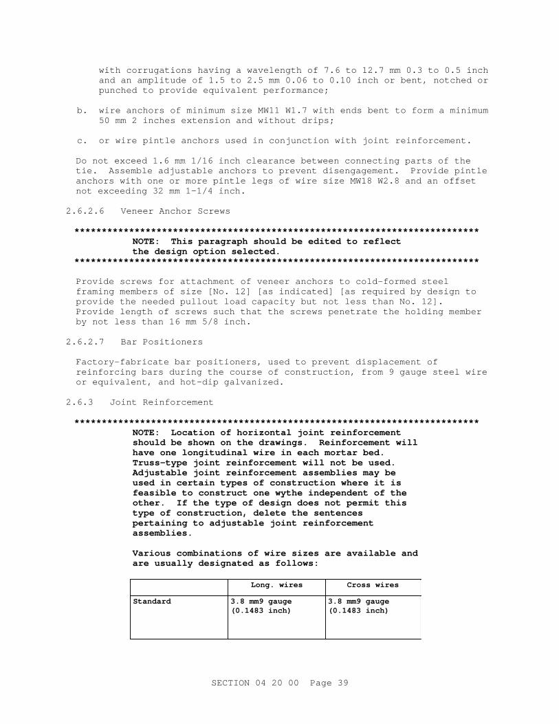
wi t h cor r ugat i ons havi ng a wavel engt h of 7. 6 t o 12. 7 mm 0. 3 t o 0. 5 i nch and an ampl i t ude of 1. 5 t o 2. 5 mm 0. 06 t o 0. 10 i nch or bent , not ched or punched t o pr ovi de equi val ent per f or mance;
b. wi r e anchor s of mi ni mum si ze MW11 W1. 7 wi t h ends bent t o f or m a mi ni mum 50 mm 2 i nches ext ensi on and wi t hout dr i ps;
c. or wi r e pi nt l e anchor s used i n conj unct i on wi t h j oi nt r ei nf or cement .
Do not exceed 1. 6 mm 1/ 16 i nch c l ear ance bet ween connect i ng par t s of t he t i e. Assembl e adj ust abl e anchor s t o pr event di sengagement . Pr ovi de pi nt l e anchor s wi t h one or mor e pi nt l e l egs of wi r e s i ze MW18 W2. 8 and an of f set not exceedi ng 32 mm 1- 1/ 4 i nch.
2. 6. 2. 6 Veneer Anchor Scr ews
**************************************************************************NOTE: Thi s par agr aph shoul d be edi t ed t o r ef l ect t he desi gn opt i on sel ect ed.
**************************************************************************
Pr ovi de scr ews f or at t achment of veneer anchor s t o col d- f or med st eel f r ami ng member s of s i ze [ No. 12] [ as i ndi cat ed] [ as r equi r ed by desi gn t o pr ovi de t he needed pul l out l oad capaci t y but not l ess t han No. 12] . Pr ovi de l engt h of scr ews such t hat t he scr ews penet r at e t he hol di ng member by not l ess t han 16 mm 5/ 8 i nch.
2. 6. 2. 7 Bar Posi t i oner s
Fact or y- f abr i cat e bar posi t i oner s, used t o pr event di spl acement of r ei nf or c i ng bar s dur i ng t he cour se of const r uct i on, f r om 9 gauge st eel wi r e or equi val ent , and hot - di p gal vani zed.
2. 6. 3 Joi nt Rei nf or cement
**************************************************************************NOTE: Locat i on of hor i zont al j oi nt r ei nf or cement shoul d be shown on t he dr awi ngs. Rei nf or cement wi l l have one l ongi t udi nal wi r e i n each mor t ar bed. Tr uss- t ype j oi nt r ei nf or cement wi l l not be used. Adj ust abl e j oi nt r ei nf or cement assembl i es may be used i n cer t ai n t ypes of const r uct i on wher e i t i s f easi bl e t o const r uct one wyt he i ndependent of t he ot her . I f t he t ype of desi gn does not per mi t t hi s t ype of const r uct i on, del et e t he sent ences per t ai ni ng t o adj ust abl e j oi nt r ei nf or cement assemblies.
Var i ous combi nat i ons of wi r e s i zes ar e avai l abl e and ar e usual l y desi gnat ed as f ol l ows:
Long. wi r es Cr oss wi r es
Standard 3. 8 mm9 gauge ( 0. 1483 i nch)
3. 8 mm9 gauge ( 0. 1483 i nch)
SECTI ON 04 20 00 Page 39
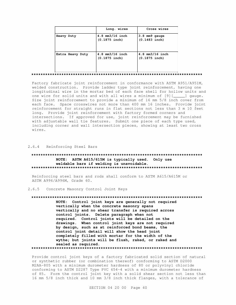
Long. wi r es Cr oss wi r es
Heavy Dut y 4. 8 mm3/ 16 i nch ( 0. 1875 i nch)
3. 8 mm9 gauge ( 0. 1483 i nch)
Ext r a Heavy Dut y 4. 8 mm3/ 16 i nch ( 0. 1875 i nch)
4. 8 mm3/ 16 i nch ( 0. 1875 i nch)
**************************************************************************
Fact or y f abr i cat e j oi nt r ei nf or cement i n conf or mance wi t h ASTM A951/ A951M, wel ded const r uct i on. Pr ovi de l adder t ype j oi nt r ei nf or cement , havi ng one l ongi t udi nal wi r e i n t he mor t ar bed of each f ace shel l f or hol l ow uni t s and one wi r e f or sol i d uni t s and wi t h al l wi r es a mi ni mum of [ 9] [ _____] gauge. Si ze j oi nt r ei nf or cement t o pr ovi de a mi ni mum of 16 mm 5/ 8 i nch cover f r om each f ace. Space cr osswi r es not mor e t han 400 mm 16 i nches. Pr ovi de j oi nt r ei nf or cement f or st r ai ght r uns i n f l at sect i ons not l ess t han 3 m 10 f eet l ong. Pr ovi de j oi nt r ei nf or cement wi t h f act or y f or med cor ner s and i nt er sect i ons. I f appr oved f or use, j oi nt r ei nf or cement may be f ur ni shed wi t h adj ust abl e wal l t i e f eat ur es. Submi t one pi ece of each t ype used, i ncl udi ng cor ner and wal l i nt er sect i on pi eces, showi ng at l east t wo cr oss wires.
2. 6. 4 Rei nf or c i ng St eel Bar s
**************************************************************************NOTE: ASTM A615/ 615M i s t ypi cal l y used. Onl y use wel dabl e bar s i f wel di ng i s unavoi dabl e.
**************************************************************************
Rei nf or c i ng st eel bar s and r ods shal l conf or m t o ASTM A615/ A615M or ASTM A996/ A996M, Gr ade 60.
2. 6. 5 Concr et e Masonr y Cont r ol Joi nt Keys
**************************************************************************NOTE: Cont r ol j oi nt keys ar e gener al l y not r equi r ed ver t i cal l y when t he concr et e masonr y spans ver t i cal l y and no shear t r ansf er i s r equi r ed acr oss cont r ol j oi nt s. Del et e par agr aph when not r equi r ed. Cont r ol j oi nt s wi l l be det ai l ed on t he dr awi ngs. When cont r ol j oi nt keys ar e not r equi r ed by desi gn, such as at r ei nf or ced bond beams, t he cont r ol j oi nt det ai l wi l l show t he head j oi nt compl et el y f i l l ed wi t h mor t ar f or t he wi dt h of t he wyt he; but j oi nt s wi l l be f l ush, r aked, or r aked and seal ed as r equi r ed.
**************************************************************************
Pr ovi de cont r ol j oi nt keys of a f act or y f abr i cat ed sol i d sect i on of nat ur al or synt het i c r ubber ( or combi nat i on t her eof ) conf or mi ng t o ASTM D2000 M2AA- 805 wi t h a mi ni mum dur omet er har dness of 80 or pol yvi nyl chl or i de conf or mi ng t o ASTM D2287 Type PVC 654- 4 wi t h a mi ni mum dur omet er har dness of 85. For m t he cont r ol j oi nt key wi t h a sol i d shear sect i on not l ess t han 16 mm 5/ 8 i nch t hi ck and 10 mm 3/ 8 i nch t hi ck f l anges, wi t h a t ol er ance of
SECTI ON 04 20 00 Page 40
pl us or mi nus 1. 5 mm 1/ 16 i nch, t o f i t neat l y, but wi t hout f or c i ng, i n masonr y uni t j amb sash gr ooves.
2. 6. 6 Cl ay Masonr y Expansi on- Joi nt Mat er i al s
**************************************************************************NOTE: Usi ng i nt er i or l ow- VOC pr oduct s cont r i but es t o meet i ng t he r equi r ement s of Sect i on 01 33 29 SUSTAI NABI LI TY REPORTI NG.
**************************************************************************
Pr ovi de backer r od and seal ant , adequat e t o accommodat e j oi nt compr essi on and ext ensi on equal t o 50 per cent of t he wi dt h of t he j oi nt . Pr ovi de t he backer r od of compr essi bl e r od st ock of c l osed cel l pol yet hyl ene f oam, pol yur et hane f oam, but y l r ubber f oam, or ot her f l exi bl e, nonabsor pt i ve mat er i al as r ecommended by t he seal ant manuf act ur er . Pr ovi de seal ant i n conf or mance wi t h Sect i on 07 92 00 JOI NT SEALANTS[ wi t h a maxi mum vol at i l e or gani c compound ( VOC) cont ent of 600 gr ams/ l i t er ] .
Submi t one pi ece of each t ype of mat er i al used.
2. 6. 7 Thr ough Wal l Fl ashi ng and Weeps
**************************************************************************NOTE: Requi r e f l ashi ng i n ext er i or masonr y wal l s, i ncl udi ng s i ngl e- wyt he const r uct i on, at al l obst r uct i ons such as bond beams, s i l l s , l i nt el s, shel f angl es, and concr et e t i e beams. The wal l desi gn and det ai l i ng must conf or m t o Nat i onal Concr et e Masonr y Associ at i on ( NCMA) publ i cat i ons: TEK 19- 2B, " Desi gn f or Dr y Si ngl e- Wyt he Concr et e Masonr y Wal l s" ; TEK 19- 4A, " Fl ashi ng St r at egi es f or Concr et e Masonr y Wal l s" ; TEK 19- 5A, " Fl ashi ng Det ai l s f or Concr et e Masonr y Wal l s" ; TEK 10- 2C, " Cont r ol Joi nt s f or Concr et e Masonr y Wal l s" ; and BI A Techni cal Not es 7 Wat er Penet r at i on, Resi st ance. Show l ocat i ons and det ai l s on pr oj ect dr awi ngs. Thi s i s a r egi onal r equi r ement whi ch shal l be used, when appl i cabl e, f or NAVFAC SE pr oj ect s; when appr opr i at e, t he r equi r ement s may be used f or pr oj ect s i n ot her ar eas.
Copper may st ai n masonr y and det er i or at e i n hi gh chl or i de envi r onment s. Def or med copper may be speci f i ed onl y when mor t ar must bond t o t he f l ashi ng, such as under copi ngs wi t hout dowel s.
Thr ough wal l f l ashi ng of s i ngl e wyt he wal l s i s not appr opr i at e f or al l appl i cat i ons. Omi t t hi s sect i on when desi gn r equi r es sei smi c shear r esi st ance of t he masonr y wal l .
**************************************************************************
2. 6. 7. 1 General
Pr ovi de coat ed copper , copper or st ai nl ess st eel sheet , sel f - adhesi ve r ubber i zed sheet , or r ei nf or ced membr ane sheet f l ashi ng [ except t hat f l ashi ng i ndi cat ed t o t er mi nat e i n r egl et s shal l be met al or coat ed- met al f l ashi ng] [ and] [ except t hat t he mat er i al shal l be one whi ch i s not
SECTI ON 04 20 00 Page 41

adver sel y af f ect ed by damppr oof i ng mat er i al . ]
2. 6. 7. 2 Coat ed- Copper Fl ashi ng
Pr ovi de 0. 2 kg 7 ounce, el ect r ol yt i c copper sheet , uni f or ml y coat ed on bot h s i des wi t h aci dpr oof , al kal i pr oof , asphal t i mpr egnat ed kr af t paper or pol yet hyl ene sheet s.
2. 6. 7. 3 Copper or St ai nl ess St eel Fl ashi ng
Pr ovi de copper sheet , compl yi ng wi t h ASTM B370, mi ni mum 450 kg 16 ounce wei ght ; or st ai nl ess st eel , ASTM A167, Type 304 or 316, 0. 4 mm 0. 015 i nch t hi ck, No. 2D f i ni sh. [ Wher e i ndi cat ed, pr ovi de wi t h f act or y- f abr i cat ed def or mat i ons t hat mechani cal l y bond f l ashi ng agai nst hor i zont al movement i n al l di r ect i ons, wher e def or mat i ons consi st of di mpl es, di agonal cor r ugat i ons, or a combi nat i on of di mpl es and t r ansver se cor r ugat i ons. ]
[ 2. 6. 7. 4 Rei nf or ced Membr ane Fl ashi ng
Pr ovi de pol yest er f i l m cor e wi t h a r ei nf or c i ng f i ber gl ass scr i m bonded t o one si de. Pr ovi de membr ane t hat i s i mper vi ous t o moi st ur e, f l exi bl e, i s not af f ect ed by caust i c al kal i s , and af t er bei ng exposed f or not l ess t han 1/ 2 hour t o a t emper at ur e of 0 degr ees C 32 degr ees F, shows no cr acki ng when, at t hat t emper at ur e, i t i s bent 180 degr ees over a 2 mm 1/ 16 i nch di amet er mandr el and t hen bent at t he same poi nt over t he same si ze mandr el i n t he opposi t e di r ect i on 360 degr ees.
] 2. 6. 7. 5 Rubber i zed Fl ashi ng
Pr ovi de sel f - adhesi ve r ubber i zed asphal t sheet f l ashi ng consi st i ng of 0. 8 mm 32- mi l t hi ck pl i abl e and hi ghl y adhesi ve r ubber i zed asphal t compound bonded compl et el y and i nt egr al l y t o 0. 2 8- mi l t hi ck, hi gh densi t y, cr oss- l ami nat ed pol yet hyl ene f i l m t o pr oduce an over al l t hi ckness of 1 mm 40 mi l s. Pr ovi de r ubber i zed, asphal t - based mast i c and sur f ace condi t i oner t hat ar e each appr oved by f l ashi ng manuf act ur er f or use wi t h f l ashi ng material.
2. 6. 7. 6 Weep Vent i l at or s
Pr ovi de weep vent i l at or s t hat ar e pr ef abr i cat ed f r om st ai nl ess st eel or pl ast i c. Pr ovi de i nser t s wi t h gr i l l or l ouver - t ype openi ngs desi gned t o al l ow t he passage of moi st ur e f r om cavi t i es and t o pr event t he ent r ance of i nsect s, and wi t h a r ect angul ar c l osur e st r i p t o pr event mor t ar dr oppi ngs f r om cl oggi ng t he openi ng. Pr ovi de vent i l at or s wi t h compr essi bl e f l anges t o f i t i n a st andar d 10 mm 3/ 8 i nch wi de mor t ar j oi nt and wi t h hei ght equal t o t he nomi nal hei ght of t he uni t . .
2. 6. 7. 7 Met al Dr i p Edge
Pr ovi de st ai nl ess st eel dr i p edge, 0. 4 mm 15- mi l t hi ck, hemmed edges, wi t h down- t ur ned dr i p at t he out s i de edge and upt ur ned dam at t he i nsi de edge f or use wi t h membr ane f l ashi ngs.
2. 6. 8 RI GI D BOARD- TYPE I NSULATI ON
**************************************************************************NOTE: I nser t t he appr opr i at e t hi ckness and R- Val ue t o be used f or t he i nsul at i on. The t ot al R- val ue f or t he i nsul at i on and t he t ot al t hi ckness of t he
SECTI ON 04 20 00 Page 42
i nsul at i on must be coor di nat ed t o f i t t he space pr ovi ded wi t hi n t he wal l cavi t y. The t hi ckness of t he i nsul at i on must al l ow f or not l ess t han 19 mm 3/ 4 i nch ai r space bet ween t he i nsul at i on and t he f aci ng veneer . Thi s wi l l l i mi t t he i nsul at i on t hi ckness t o 50 mm 2 i nches i n a 70 mm 2- 3/ 4 i nch) cavi t y space. I f gr eat er i nsul at i on t hi ckness i s r equi r ed t he masonr y wal l must be desi gned t o pr ovi de a l ar ger cavi t y.
To assur e adequat e compet i t i on, an R- val ue shoul d be chosen t hat al l ows sever al pr oduct s t o meet t he speci f i ed t hi ckness. The r ange of desi gn R- val ues ( i n I P uni t s) f or f oam i nsul at i ons gi ven by ASHRAE i s 5 t o 7 per i nch. Ver i f y r ange avai l abl e f r om manuf act ur er s. An aged R- val ue i n SI uni t s of 2 I P uni t s of 11) can be r eadi l y achi eved wi t h 50 mm 2 i nches of i nsul at i on.
Cel l ul ar pl ast i c i nsul at i ons ( pol yst yr ene, pol yur et hane and pol y i socyanur at e) ar e t her mal l y ef f i c i ent , however , cer t ai n pr ecaut i ons shoul d be obser ved i n t hei r use due t o hi gh smoke devel opment and t oxi c i t y of t he smoke gener at ed by t he bur ni ng of t hese mat er i al s. Cel l ul ar pl ast i c i nsul at i ons shoul d onl y be used i n anchor ed veneer masonr y wal l s wher e t he i nsul at i on i s compl et el y i sol at ed f r om t he i nt er i or of t he bui l di ng by masonr y, i ncl udi ng al l penet r at i ons of t he i nt er i or wyt he.
**************************************************************************
Pr ovi de r i gi d boar d- t ype i nsul at i on as speci f i ed i n Sect i on 07 21 13 BOARD AND BLOCK I NSULATI ON.
PART 3 EXECUTI ON
3. 1 EXAMINATION
Pr i or t o st ar t of wor k, ver i f y t he appl i cabl e condi t i ons as set f or t h i n TMS MSJC, i nspect i on.
3. 2 PREPARATION
3. 2. 1 Stains
Pr ot ect exposed sur f aces f r om mor t ar and ot her st ai ns. When mor t ar j oi nt s ar e t ool ed, r emove mor t ar f r om exposed sur f aces wi t h f i ber br ushes and wooden paddl es. Pr ot ect base of wal l s f r om spl ash st ai ns by cover i ng adj acent gr ound wi t h sand, sawdust , or pol yet hyl ene.
3. 2. 2 Loads
Do not appl y uni f or m l oads f or at l east 12 hour s or concent r at ed l oads f or at l east 72 hour s af t er masonr y i s const r uct ed. Pr ovi de t empor ar y br aci ng as r equi r ed.
3. 2. 3 Concr et e Sur f aces
Wher e masonr y i s t o be pl aced, c l ean concr et e of l ai t ance, dust , di r t , oi l ,
SECTI ON 04 20 00 Page 43

or gani c mat t er , or ot her f or ei gn mat er i al s and sl i ght l y r oughen t o pr ovi de a sur f ace t ext ur e wi t h a dept h of at l east 3 mm 1/ 8 i nch. Sandbl ast , i f necessar y, t o r emove l ai t ance f r om por es and t o expose t he aggr egat e.
3. 2. 4 Shel f Angl es
Adj ust shel f angl es as r equi r ed t o keep t he masonr y l evel and at t he pr oper elevation.
3. 2. 5 Bracing
**************************************************************************NOTE: TMS MSJC, Ar t i c l e 3. 3 E Comment ar y r ef er ences " St andar d Pr act i ce f or Br aci ng Masonr y Wal l s Under Const r uct i on" f or gui dance on wal l br aci ng r equi r ement s. Desi gn wi nd pr essur e f or br aci ng desi gn i s l ower t han t hat r equi r ed by bui l di ng code f or l ong t er m bui l di ng per f or mance.
**************************************************************************
Pr ovi de br aci ng and scaf f ol di ng necessar y f or masonr y wor k. Desi gn br aci ng t o r esi st wi nd pr essur e as r equi r ed by OSHA and l ocal codes and submi t br aci ng cal cul at i ons, seal ed by a r egi st er ed pr of essi onal engi neer . Do not r emove br aci ng i n l ess t han 10 days.
3. 3 ERECTION
**************************************************************************NOTE: Speci f y bond pat t er n f or each t ype of masonr y. Wher e mor e t han one bond pat t er n i s r equi r ed, t he dr awi ngs shoul d i ndi cat e t he l ocat i on and ext ent of each bond pat t er n. Bond pat t er ns f or r ei nf or ced hol l ow masonr y const r uct i on shoul d be such t hat cor es of uni t s wi l l be i n ver t i cal al i gnment . Per f ect ver t i cal al i gnment of cel l s may r equi r e speci al masonr y uni t s. Wher e st acked bond i s speci f i ed i n r ei nf or ced hol l ow masonr y, hor i zont al r ei nf or c i ng bar s shal l be pr ovi ded at maxi mum 1220 mm 4 f oot i nt er val s or hor i zont al j oi nt r ei nf or cement must be r equi r ed i n ever y ot her hor i zont al j oi nt t o pr ovi de mechani cal bond bet ween adj acent uni t s. When veneer i s speci f i ed t o be l ai d i n st ack bond and t he pr oj ect i s i n Sei smi c Desi gn Cat egor y E or hi gher , hor i zont al j oi nt r ei nf or cement consi st i ng of a s i ngl e wi r e s i ze MW11 W1. 7 i s r equi r ed at a maxi mum spaci ng of 460 mm 18 i nches. The use of st acked bond i s di scour aged and shoul d onl y be per mi t t ed f or smal l wal l ar eas t o gi ve an ar chi t ect ur al f eat ur e, such as f or a bui l di ng ent r ance det ai l .
**************************************************************************
3. 3. 1 General
a. Coor di nat e masonr y wor k wi t h t he wor k of ot her t r ades t o accommodat e bui l t - i n i t ems and t o avoi d cut t i ng and pat chi ng. Lay masonr y uni t s i n [ r unni ng] [ st acked] [ t he i ndi cat ed] bond pat t er n. Lay f aci ng cour ses l evel wi t h back- up cour ses, unl ess t he use of adj ust abl e t i es has been appr oved i n whi ch case t he t ol er ances i s pl us or mi nus 13 mm 1/ 2 i nch.
SECTI ON 04 20 00 Page 44
Adj ust each uni t t o i t s f i nal posi t i on whi l e mor t ar i s st i l l sof t and has pl ast i c consi st ency.
b. Remove and c l ean uni t s t hat have been di st ur bed af t er t he mor t ar has st i f f ened, and r el ay wi t h f r esh mor t ar . Keep ai r spaces, cavi t i es, chases, expansi on j oi nt s, and spaces t o be gr out ed f r ee f r om mor t ar and ot her debr i s. Sel ect uni t s t o be used i n exposed masonr y sur f aces f r om t hose havi ng t he l east amount of chi pped edges or ot her i mper f ect i ons det r act i ng f r om t he appear ance of t he f i ni shed wor k.
c. When necessar y t o t empor ar i l y di scont i nue t he wor k, st ep ( r ack) back t he masonr y f or j oi ni ng when wor k r esumes. Toot hi ng may be used onl y when speci f i cal l y appr oved by t he Cont r act i ng Of f i cer . Bef or e r esumi ng wor k, r emove l oose mor t ar and t hor oughl y c l ean t he exposed j oi nt . Cover t he t op of wal l s subj ect ed t o r ai n or snow wi t h nonst ai ni ng wat er pr oof cover i ng or membr ane when wor k i s not i n pr ocess. Ext end t he cover i ng a mi ni mum of 610 mm 2 f eet down on each si de of t he wal l and hol d secur el y i n pl ace.
d. Ensur e t hat uni t s bei ng l ai d and sur f aces t o r ecei ve uni t s ar e f r ee of wat er f i l m and f r ost . Lay sol i d uni t s i n a nonf ur r owed f ul l bed of mor t ar . Bevel mor t ar f or veneer wyt hes and sl ope down t owar d t he cavi t y s i de. Shove uni t s i nt o pl ace so t hat t he ver t i cal j oi nt s ar e t i ght . Compl et el y f i l l ver t i cal j oi nt s bet ween sol i d uni t s wi t h mor t ar , except wher e i ndi cat ed at cont r ol , expansi on, and i sol at i on j oi nt s. Pl ace hol l ow uni t s so t hat mor t ar ext ends t o t he dept h of t he f ace shel l at heads and beds, unl ess ot her wi se i ndi cat ed. Mor t ar wi l l be per mi t t ed t o pr ot r ude up t o 13 mm 1/ 2 i nch i nt o t he space or cel l s t o be gr out ed. Pr ovi de means t o pr event mor t ar f r om dr oppi ng i nt o t he space bel ow or c l ean gr out spaces pr i or t o gr out i ng.
e. I n mul t i - wyt he const r uct i on wi t h col l ar j oi nt s no mor e t han 20 mm 3/ 4 i nch wi de, br i ng up t he i nner wyt he not mor e t han 400 mm 16 i nches ahead of t he out er wyt he. Fi l l col l ar j oi nt s wi t h mor t ar dur i ng t he l ayi ng of t he f aci ng wyt he, and f i l l i ng shal l not l ag t he l ayi ng of t he f aci ng wyt he by back- but t er i ng each uni t as i t i s l ai d.
3. 3. 1. 1 Jointing
Tool mor t ar j oi nt s when t he mor t ar i s t humbpr i nt har d. Tool hor i zont al j oi nt s af t er t ool i ng ver t i cal j oi nt s. Br ush mor t ar j oi nt s t o r emove l oose and excess mor t ar .
3. 3. 1. 1. 1 Tool ed Joi nt s
**************************************************************************NOTE: Joi nt s i n ext er i or masonr y wal l s exposed t o weat her wi l l be t ool ed wi t h an appr oved mor t ar j oi nt er , t ypi cal l y a concave j oi nt er . Ot her j oi nt s t hat ar e sui t abl e f or weat her t i ght const r uct i on and may be consi der ed f or ar chi t ect ur al pur poses ar e: Vee, Beaded, or Weat her ed t ypes. Exposed t o v i ew or pai nt ed i nt er i or masonr y wal l s wi l l al so be t ool ed, t ypi cal l y wi t h a s l i ght l y concaved j oi nt , but may al so be t ool ed wi t h ot her j oi nt t ypes as ar chi t ect ur al l y desi r ed.
**************************************************************************
Tool mor t ar j oi nt s i n exposed ext er i or and i nt er i or masonr y sur f aces
SECTI ON 04 20 00 Page 45
[ concave] [ _____] , usi ng a j oi nt er t hat i s s l i ght l y l ar ger t han t he j oi nt wi dt h so t hat compl et e cont act i s made al ong t he edges of t he uni t . Per f or m t ool i ng so t hat t he mor t ar i s compr essed and t he j oi nt sur f ace i s seal ed. Use a j oi nt er of suf f i c i ent l engt h t o obt ai n a st r ai ght and t r ue mor t ar j oi nt .
3. 3. 1. 1. 2 Fl ush Joi nt s
**************************************************************************NOTE: Label " wet ar eas" on t he dr awi ngs.
**************************************************************************
Fl ush cut mor t ar j oi nt s i n conceal ed masonr y sur f aces and j oi nt s at el ect r i cal out l et boxes i n wet ar eas. Fi ni sh f l ush cut j oi nt s by cut t i ng of f t he mor t ar f l ush wi t h t he f ace of t he wal l . Poi nt j oi nt s i n unpar ged masonr y wal l s bel ow gr ade t i ght . For ar chi t ect ur al uni t s, such as f l ut ed uni t s, compl et el y f i l l bot h t he head and bed j oi nt s and f l ush cut .
3. 3. 1. 1. 3 Door and Wi ndow Fr ame Joi nt s
On t he exposed i nt er i or s i de of ext er i or f r ames, j oi nt s bet ween f r ames and abut t i ng masonr y wal l s shal l be r aked t o a dept h of 10 mm 3/ 8 i nch. On t he ext er i or s i de of ext er i or f r ames, j oi nt s bet ween f r ames and abut t i ng masonr y wal l s shal l be r aked t o a dept h of 10 mm 3/ 8 i nch.
3. 3. 1. 1. 4 Joi nt Wi dt hs
a. Const r uct br i ck masonr y wi t h mor t ar j oi nt wi dt hs equal t o t he di f f er ence bet ween t he speci f i ed and nomi nal di mensi ons of t he uni t , wi t hi n t ol er ances per mi t t ed by TMS MSJC.
b. Pr ovi de 10 mm 3/ 8 i nch wi de mor t ar j oi nt s i n concr et e masonr y, except f or pr ef aced concr et e masonr y uni t s.
c. Pr ovi de 10 mm 3/ 8 i nch wi de mor t ar j oi nt s on unf aced si de of pr ef aced concr et e masonr y uni t s and not l ess t han 5 mm 3/ 16 i nch nor mor e t han 6 mm 1/ 4 i nch wi de on pr ef aced si de.
d. Mai nt ai n mor t ar j oi nt wi dt hs wi t hi n t ol er ances per mi t t ed by TMS MSJC
3. 3. 1. 2 Cut t i ng and Fi t t i ng
Use f ul l uni t s of t he pr oper s i ze wher ever possi bl e, i n l i eu of cut uni t s. Locat e cut uni t s wher e t hey woul d have t he l east i mpact on t he ar chi t ect ur al aest het i c goal s of t he f aci l i t y . Per f or m cut t i ng and f i t t i ng, i ncl udi ng t hat r equi r ed t o accommodat e t he wor k of ot her s, by masonr y mechani cs usi ng power masonr y saws. Concr et e masonr y uni t s may be wet or dr y cut . Bef or e bei ng pl aced i n t he wor k, dr y wet - cut uni t s t o t he same sur f ace- dr y appear ance as uncut uni t s bei ng l ai d i n t he wal l . Pr ovi de cut edges t hat ar e c l ean, t r ue and shar p.
a. Car ef ul l y make openi ngs i n t he masonr y so t hat wal l pl at es, cover pl at es or escut cheons r equi r ed by t he i nst al l at i on wi l l compl et el y conceal t he openi ngs and wi l l have bot t oms par al l el wi t h t he masonr y bed j oi nt s. Pr ovi de r ei nf or ced masonr y l i nt el s above openi ngs over 300 mm 12 i nches wi de f or pi pes, duct s, cabl e t r ays, and ot her wal l penet r at i ons, unl ess st eel s l eeves ar e used.
b. Do not r educe masonr y uni t s i n s i ze by mor e t han one- t hi r d i n hei ght
SECTI ON 04 20 00 Page 46

and one- hal f i n l engt h. Do not l ocat e cut pr oduct s at ends of wal l s, cor ner s, and ot her openi ngs.
3. 3. 1. 3 Unf i ni shed Wor k
Rack back unf i ni shed wor k f or j oi ni ng wi t h new wor k. Toot hi ng may be r esor t ed t o onl y when speci f i cal l y appr oved by t he Cont r act i ng Of f i cer . Remove l oose mor t ar and t hor oughl y c l ean t he exposed j oi nt s bef or e l ayi ng new wor k.
3. 3. 1. 4 Cl ay Masonr y Expansi on Joi nt s
**************************************************************************NOTE: Expansi on j oi nt s i n c l ay or shal e masonr y wi l l be l ocat ed and det ai l ed on t he dr awi ngs. The wal l desi gn and det ai l i ng must conf or m t o BI A Techni cal Not es 18A Accommodat i ng Expansi on of Brickwork.
**************************************************************************
Pr ovi de c l ay masonr y expansi on j oi nt s as i ndi cat ed. Const r uct by [ l eavi ng a gap] [ f i l l i ng wi t h a compr essi bl e f oam pad] . Ensur e t hat no mor t ar or ot her noncompr essi bl e mat er i al s ar e wi t hi n t he j oi nt . I nst al l backer r od and seal ant i n accor dance wi t h Sect i on 07 92 00 JOI NT SEALANTS.
3. 3. 1. 5 Cont r ol Joi nt s
**************************************************************************NOTE: Cont r ol j oi nt s wi l l be l ocat ed and det ai l ed on t he dr awi ngs. The wal l desi gn and det ai l i ng f or movement cont r ol must conf or m t o Nat i onal Concr et e Masonr y Associ at i on ( NCMA) publ i cat i ons: TEK 10- 01A, and 10- 02C or 10- 03 or 10- 04, as appl i cabl e. When cont r ol j oi nt keys ar e r equi r ed, i t i s t he Cont r act or ' s opt i on t o use ei t her speci al cont r ol j oi nt uni t s or sash j amb uni t s wi t h cont r ol j oi nt keys. I f one i s pr ef er r ed over t he ot her i n t he desi gn, edi t t hi s par agr aph accor di ngl y and pr ovi de speci f i c det ai l s on t he dr awi ngs. St andar d i ndust r y pr act i ce i s t o di scont i nue hor i zont al r ei nf or cement at cont r ol j oi nt s except at f l oor and r oof di aphr agms, wher e t he r ei nf or cement must be cont i nuous. Wher e hor i zont al shear r ei nf or cement i s needed by desi gn, however , t he r ei nf or cement must be cont i nuous t hr ough t he cont r ol j oi nt . Sel ect t he appr opr i at e opt i on.
**************************************************************************
Pr ovi de cont r ol j oi nt s i n concr et e masonr y as i ndi cat ed. Const r uct by [ r aki ng out mor t ar wi t hi n t he head j oi nt ] [ usi ng speci al cont r ol - j oi nt uni t s] [ usi ng sash j amb uni t s wi t h cont r ol j oi nt key] [ usi ng open end st r et cher uni t s pl aced wi t h t he c l osed end at t he j oi nt ] i n accor dance wi t h t he det ai l s shown on t he Dr awi ngs. For m a cont i nuous ver t i cal j oi nt at cont r ol j oi nt l ocat i ons, i ncl udi ng t hr ough bond beams, by ut i l i z i ng hal f bl ocks i n al t er nat i ng cour ses on each si de of t he j oi nt . I nt er r upt t he cont r ol j oi nt key i n cour ses cont ai ni ng cont i nuous bond beam r ei nf or cement . [ Do not i nt er r upt t he hor i zont al r ei nf or cement and gr out at t he cont r ol j oi nt . ] [ I nt er r upt t he hor i zont al r ei nf or cement and gr out i n bond beams at t he cont r ol j oi nt except i n bond beams at t he f l oor and r oof
SECTI ON 04 20 00 Page 47
diaphragms.]
Wher e mor t ar was pl aced i n t he j oi nt , r ake bot h f aces of t he cont r ol j oi nt s t o a dept h of 19 mm 3/ 4 i nch. I nst al l backer r od and seal ant on bot h f aces i n accor dance wi t h Sect i on 07 92 00 JOI NT SEALANTS.
3. 3. 1. 6 Decor at i ve Ar chi t ect ur al Uni t s
Pl ace decor at i ve masonr y uni t s wi t h t he pat t er ned f ace shel l pr oper l y al i gned i n t he compl et ed wal l .
3. 3. 2 Cl ay or Shal e Br i ck Masonr y
**************************************************************************NOTE: Speci f y t ype of bond r equi r ed, i f ot her t han r unni ng bond i s desi r ed.
**************************************************************************
3. 3. 2. 1 Br i ck Pl acement
Bl end al l br i ck at t he j obsi t e f r om sever al cubes t o pr oduce a uni f or m appear ance when i nst al l ed. An obser vabl e " bandi ng" or " l ayer i ng" of col or s or t ext ur es caused by i mpr oper l y mi xed br i ck i s unaccept abl e. Lay br i ck f aci ng wi t h t he bet t er f ace exposed. Lay br i ck i n r unni ng bond wi t h each cour se bonded at cor ner s, unl ess ot her wi se i ndi cat ed. Lay mol ded br i ck wi t h t he f r og s i de down. Do not l ay br i ck t hat i s cor ed, r ecessed, or has ot her def or mat i ons i n a manner t hat al l ows t hose def or mat i ons t o be exposed t o v i ew; l ay 100 per cent sol i d uni t s i n t hese ar eas. Compl et el y f i l l head and bed j oi nt s of sol i d uni t s wi t h mor t ar . Lay hol l ow uni t s wi t h mor t ar j oi nt s as speci f i ed f or concr et e masonr y uni t s. [ Lay f i r e br i ck by di ppi ng each br i ck i n a sof t mi xt ur e of f i r e c l ay and wat er and t hen r ubbi ng t he br i ck i nt o pl ace wi t h j oi nt s as t hi n as pr act i cabl e or pr ovi de r ef r act or y mor t ar wi t h j oi nt s not mor e t han 10 mm 3/ 8 i nch t hi ck. ]
Pl ace ext er i or f ace of sal vaged br i cks t owar ds t he ext er i or .
3. 3. 2. 2 Wet t i ng of Uni t s
**************************************************************************NOTE: I f c l ay, shal e br i ck, or hol l ow br i ck i s speci f i ed, i ncl ude wet t i ng r equi r ement s f or uni t s havi ng an i ni t i al r at e of absor pt i on ( I RA) of mor e t han 0. 155 gm per mi nut e per squar e cm 1 gm per mi nut e per squar e i nch of bed sur f ace.
I RA i s measur ed i n t he l abor at or y and r epor t ed i n t est r esul t s. However , t he I RA can i ncr ease under hot weat her condi t i ons i n t he f i el d. The wax penci l t est can appr oxi mat e t he f i el d I RA condi t i on.
**************************************************************************
Wet t i ng of c l ay, shal e br i ck, or hol l ow br i ck uni t s havi ng an i ni t i al r at e of absor pt i on of mor e t han 0. 155 gm per mi nut e per squar e cm 1 gr am per mi nut e per squar e i nch of bed sur f ace shal l be i n conf or mance wi t h ASTM C67. Ensur e t hat each uni t i s near l y sat ur at ed when wet t ed but sur f ace dr y when laid.
Test c l ay or shal e br i ck dai l y on t he j ob, pr i or t o l ayi ng, as f ol l ows: Usi ng a wax penci l , dr aw a c i r c l e t he s i ze of a quar t er on f i ve r andoml y
SECTI ON 04 20 00 Page 48
sel ect ed br i cks. Appl y 20 dr ops of wat er wi t h a medi c i ne dr opper t o t he sur f ace wi t hi n t he c i r c l e on each br i ck. I f t he aver age t i me t hat t he wat er i s compl et el y absor bed i n t he f i ve br i cks i s l ess t han 1- 1/ 2 mi nut es, wet br i cks r epr esent ed by t he f i ve br i cks t est ed.
3. 3. 2. 3 Br i ck Si l l s
**************************************************************************NOTE: Br i ck s i l l s ar e mor e suscept i bl e t o f r eeze- / t haw damage and shoul d be car ef ul l y consi der ed i n f r eezi ng c l i mat es.
**************************************************************************
Lay br i ck on edge, s l ope not l ess t han 19 mm 3/ 4 i nch downwar d t o t he out s i de, and pr oj ect not l ess t han 13 mm 1/ 2 i nch beyond t he f ace of t he wal l t o f or m a wash and dr i p. Fi l l al l j oi nt s sol i dl y wi t h mor t ar and t ool .
3. 3. 2. 4 Rei nf or ced Br i ck Wal l s
**************************************************************************NOTE: Mul t i - wyt he wal l s wi t h masonr y header s ar e mor e suscept i bl e t o wat er penet r at i on and efflorescence.
Show r equi r ed l engt h of r ei nf or c i ng bar l ap spl i ces on t he Dr awi ngs or by a schedul e i n t he Speci f i cat i on. Requi r ed l ap l engt h of bar s may be di f f er ent dependi ng on whet her t he masonr y i s desi gned by al l owabl e st r ess or by st r engt h.
**************************************************************************
Pr ovi de t wo wyt hes of br i ck separ at ed by a [ _____] mm i nch wi de cont i nuous space f i l l ed wi t h [ gr out ] [ br i cks " f l oat ed" i n gr out ] and r ei nf or ced as i ndi cat ed. Bevel mor t ar beds away f r om gr out space t o pr event pr oj ect i on i nt o gr out space when br i cks ar e shoved i n pl ace. Deepl y f ur r owed bed j oi nt s wi l l not be per mi t t ed. Lay ext er i or wyt he of br i ck t o t he hei ght of each gr out pour i n advance of i nt er i or wyt he. Cl ean gr out space and set r ei nf or c i ng bef or e l ayi ng i nt er i or wyt he. Pr ovi de met al t i es t o pr event spr eadi ng of t he wyt hes and t o mai nt ai n ver t i cal al i gnment of wal l s . Pl ace r ei nf or cement and gr out i n accor dance wi t h par agr aph BAR REI NFORCEMENT I NSTALLATI ON and par agr aph PLACI NG GROUT i n t hi s Sect i on.
3. 3. 2. 5 Chimneys
**************************************************************************NOTE: I f a chi mney wal l i s 200 mm 8 i nches or l ess i n t hi ckness, t he space bet ween t he f l ue l i ner and br i ckwor k shoul d be kept c l ean and cl ear t o avoi d cr acki ng t he br i ckwor k.
**************************************************************************
Const r uct chi mneys of br i ck wi t h c l ay f l ue l i ni ngs of t he s i zes i ndi cat ed. Ext end f l ue l i ni ngs f r om 300 mm 12 i nches bel ow t he smoke i nl et t o 100 mm 4 i nches above t he chi mney cap. Pl ace t hi mbl es as i ndi cat ed, f l ush wi t h i nsi de of or up t o 25 mm one i nch i nt o t he f l ue l i ni ng. Set l i ni ngs i n f i r e c l ay mor t ar or r ef r act or y mor t ar and f i l l and smoot h t he j oi nt s on t he i nsi de. Set each sect i on of f l ue l i ni ng bef or e sur r oundi ng br i ckwor k r eaches t op of f l ue l i ni ng sect i on bel ow. Bui l d br i ckwor k ar ound l i ni ng, and [ f i l l t he space] [ l eave a 25 mm one i nch ai r space] bet ween l i ni ng and
SECTI ON 04 20 00 Page 49

br i ckwor k [ wi t h gr out ] . [ Seal t op of ai r space bef or e i nst al l i ng chi mney cap. ] Do not cut l i ni ngs af t er t hey ar e i nst al l ed i n chi mney. Unl ess i ndi cat ed ot her wi se, pr ovi de a chi mney cap of ai r - ent r ai ned concr et e. Sl ope cap t o a mi ni mum edge t hi ckness of 50 mm 2 i nches and r ei nf or ce wi t h t wo r i ngs of No. 3 gage gal vani zed st eel wi r e.
3. 3. 2. 6 Partitions
**************************************************************************NOTE: Wal l s and par t i t i ons t hat ser ve as f i r e wal l s or f i r e- r at ed wal l s wi l l be shown. Sect i ons and det ai l s of t hese wal l s wi l l c l ear l y i ndi cat e t he ext ent of such wal l s. Non- st r uct ur al masonr y par t i t i on wal l s wi l l not be t i ed i n any way t o st r uct ur al or ext er i or masonr y wal l s. I sol at i on j oi nt s wi l l be used at t hese i nt er sect i ons. When 100 mm 4 i nch masonr y par t i t i ons ar e not used, del et e r ef er ence t o t hese uni t s and t hei r intersections.
**************************************************************************
a. Const r uct par t i t i ons cont i nuous f r om f l oor t o under si de of f l oor or r oof deck wher e shown. Fi l l openi ngs i n f i r ewal l s ar ound j oi st s and ot her st r uct ur al member s as i ndi cat ed or appr oved. Wher e suspended cei l i ngs on bot h s i des of par t i t i ons ar e i ndi cat ed, t he par t i t i ons ot her t han t hose shown t o be cont i nuous may be st opped appr oxi mat el y 100 mm 4 i nches above t he cei l i ng l evel . Const r uct an i sol at i on j oi nt i n t he i nt er sect i on bet ween par t i t i ons and st r uct ur al or ext er i or wal l s.
b. Ti e i nt er i or par t i t i ons havi ng 100 mm 4 i nch nomi nal t hi ckness uni t s t o i nt er sect i ng par t i t i ons of 100 mm 4 i nch uni t s, 125 mm 5 i nches i nt o par t i t i ons of 150 mm 6 i nch uni t s , and 175 7 i nches i nt o par t i t i ons of 200 mm 8 i nch or t hi cker uni t s. Cel l s wi t hi n ver t i cal pl ane of t i es shal l be f i l l ed sol i d wi t h gr out f or f ul l hei ght of par t i t i on or sol i d masonr y uni t s may be used. Ti e i nt er i or par t i t i ons over 100 mm 4 i nches t hi ck t oget her wi t h j oi nt r ei nf or cement . Pr ovi de j oi nt r ei nf or cement wi t h pr ef abr i cat ed pi eces at cor ner s and i nt er sect i ons of par t i t i ons.
c. Doubl e- Faced Bases or Par t i t i ons: Const r uct doubl e- f aced cl ay uni t bases and par t i t i ons of t wo- uni t const r uct i on. Bond uni t s by over l appi ng f r om opposi t e f aces of t he wal l , 50 mm f or 150 mm 2 i nches f or 6 i nch t hi ck par t i t i ons and 100 mm f or 200 mm 4 i nches f or 8 i nch t hi ck or gr eat er . A s i ngl e wyt he pr ef aced concr et e masonr y base or par t i t i on may be made wi t h doubl e f aced uni t s.
3. 3. 3 Anchor ed Veneer Const r uct i on
**************************************************************************NOTE: The ai r space behi nd t he veneer shoul d be a mi ni mum of 25 mm 1 i nch. The maxi mum di st ance bet ween t he i nsi de f ace of veneer and out s i de f ace of backi ng ( concr et e sur f ace, masonr y sur f ace, or wood or st eel st ud f ace) shoul d be 114 mm 4. 5 i nches, unl ess speci al l y desi gned anchor s ar e used. Coor di nat e cavi t y di mensi ons wi t h st andar d l i nt el and shel f angl e di mensi ons.
Bond pat t er n shoul d be r unni ng bond unl ess t her e ar e
SECTI ON 04 20 00 Page 50
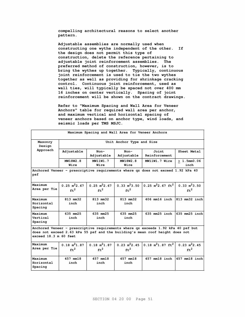
compel l i ng ar chi t ect ur al r easons t o sel ect anot her pattern.
Adj ust abl e assembl i es ar e nor mal l y used when const r uct i ng one wyt he i ndependent of t he ot her . I f t he desi gn does not per mi t t hi s t ype of const r uct i on, del et e t he r ef er ence per t ai ni ng t o adj ust abl e j oi nt r ei nf or cement assembl i es. The pr ef er r ed met hod of const r uct i on, however , i s t o br i ng t he wyt hes up t oget her . Typi cal l y , cont i nuous j oi nt r ei nf or cement i s used t o t i e t he t wo wyt hes t oget her as wel l as pr ovi di ng f or shr i nkage cr acki ng cont r ol . Cont i nuous j oi nt r ei nf or cement , used as wal l t i es, wi l l t ypi cal l y be spaced not over 400 mm 16 i nches on cent er ver t i cal l y . Spaci ng of j oi nt r ei nf or cement wi l l be shown on t he cont r act dr awi ngs.
Ref er t o " Maxi mum Spaci ng and Wal l Ar ea f or Veneer Anchor s" t abl e f or r equi r ed wal l ar ea per anchor , and maxi mum ver t i cal and hor i zont al spaci ng of veneer anchor s based on anchor t ype, wi nd l oads, and sei smi c l oads per TMS MSJC.
Maxi mum Spaci ng and Wal l Ar ea f or Veneer Anchor s
MasonryDesign
Approach
Uni t Anchor Type and Si ze
Adjustable Non-Adjustable
Non-Adjustable
JointReinforcement
Sheet Met al
MW18W2.8Wire
MW11W1.7Wire
MW18W2.8Wire
MW11W1. 7 Wi r e > 1. 5mm0. 06inch
Anchor ed Veneer - pr escr i pt i ve r equi r ement s wher e qz does not exceed 1. 92 kPa 40 psf
Maximum Ar ea per Ti e
0. 25 m22.67
ft 20. 25 m22.67
ft 20. 33 m23.50
ft 20. 25 m22. 67 f t 2 0. 33 m23.50
ft 2
Maximum Horizontal Spacing
813 mm32inch
813 mm32inch
813 mm32inch
406 mm16 i nch 813 mm32 i nch
Maximum Vertical Spacing
635 mm25inch
635 mm25inch
635 mm25inch
635 mm25 i nch 635 mm25 i nch
Anchor ed Veneer - pr escr i pt i ve r equi r ement s wher e qz exceeds 1. 92 kPa 40 psf but does not exceed 2. 63 kPa 55 psf and t he bui l di ng' s mean r oof hei ght does not exceed 18. 3 m 60 f eet
Maximum Ar ea per Ti e
0. 18 m21.87
ft 20. 18 m21.87
ft 20. 23 m22.45
ft 20. 18 m21. 87 f t 2 0. 23 m22.45
ft 2
Maximum Horizontal Spacing
457 mm18inch
457 mm18inch
457 mm18inch
457 mm18 i nch 457 mm18 i nch
SECTI ON 04 20 00 Page 51
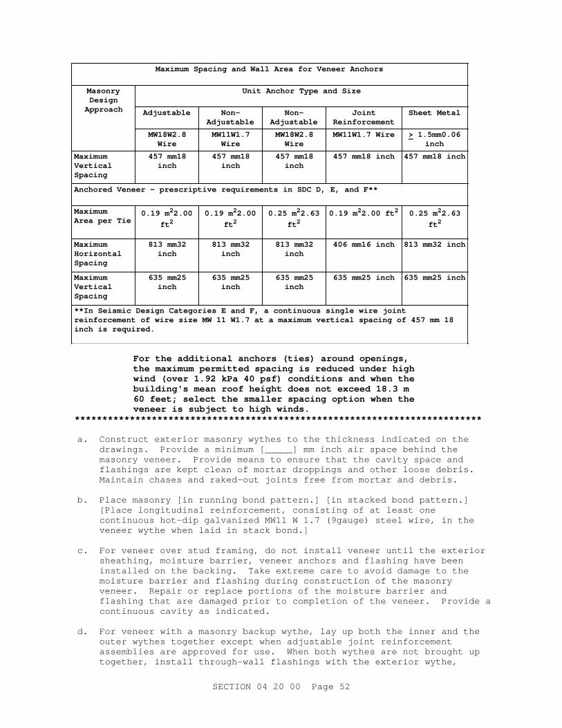
Maxi mum Spaci ng and Wal l Ar ea f or Veneer Anchor s
MasonryDesign
Approach
Uni t Anchor Type and Si ze
Adjustable Non-Adjustable
Non-Adjustable
JointReinforcement
Sheet Met al
MW18W2.8Wire
MW11W1.7Wire
MW18W2.8Wire
MW11W1. 7 Wi r e > 1. 5mm0. 06inch
Maximum Vertical Spacing
457 mm18inch
457 mm18inch
457 mm18inch
457 mm18 i nch 457 mm18 i nch
Anchor ed Veneer - pr escr i pt i ve r equi r ement s i n SDC D, E, and F* *
Maximum Ar ea per Ti e
0. 19 m22.00
ft 20. 19 m22.00
ft 20. 25 m22.63
ft 20. 19 m22. 00 f t 2 0. 25 m22.63
ft 2
Maximum Horizontal Spacing
813 mm32inch
813 mm32inch
813 mm32inch
406 mm16 i nch 813 mm32 i nch
Maximum Vertical Spacing
635 mm25inch
635 mm25inch
635 mm25inch
635 mm25 i nch 635 mm25 i nch
* * I n Sei smi c Desi gn Cat egor i es E and F, a cont i nuous si ngl e wi r e j oi nt r ei nf or cement of wi r e s i ze MW 11 W1. 7 at a maxi mum ver t i cal spaci ng of 457 mm 18 i nch i s r equi r ed.
For t he addi t i onal anchor s ( t i es) ar ound openi ngs, t he maxi mum per mi t t ed spaci ng i s r educed under hi gh wi nd ( over 1. 92 kPa 40 psf ) condi t i ons and when t he bui l di ng' s mean r oof hei ght does not exceed 18. 3 m 60 f eet ; sel ect t he smal l er spaci ng opt i on when t he veneer i s subj ect t o hi gh wi nds.
**************************************************************************
a. Const r uct ext er i or masonr y wyt hes t o t he t hi ckness i ndi cat ed on t he dr awi ngs. Pr ovi de a mi ni mum [ _____] mm i nch ai r space behi nd t he masonr y veneer . Pr ovi de means t o ensur e t hat t he cavi t y space and f l ashi ngs ar e kept c l ean of mor t ar dr oppi ngs and ot her l oose debr i s . Mai nt ai n chases and r aked- out j oi nt s f r ee f r om mor t ar and debr i s.
b. Pl ace masonr y [ i n r unni ng bond pat t er n. ] [ i n s t acked bond pat t er n. ] [ Pl ace l ongi t udi nal r ei nf or cement , consi st i ng of at l east one cont i nuous hot - di p gal vani zed MW11 W 1. 7 ( 9gauge) st eel wi r e, i n t he veneer wyt he when l ai d i n st ack bond. ]
c. For veneer over st ud f r ami ng, do not i nst al l veneer unt i l t he ext er i or sheat hi ng, moi st ur e bar r i er , veneer anchor s and f l ashi ng have been i nst al l ed on t he backi ng. Take ext r eme car e t o avoi d damage t o t he moi st ur e bar r i er and f l ashi ng dur i ng const r uct i on of t he masonr y veneer . Repai r or r epl ace por t i ons of t he moi st ur e bar r i er and f l ashi ng t hat ar e damaged pr i or t o compl et i on of t he veneer . Pr ovi de a cont i nuous cavi t y as i ndi cat ed.
d. For veneer wi t h a masonr y backup wyt he, l ay up bot h t he i nner and t he out er wyt hes t oget her except when adj ust abl e j oi nt r ei nf or cement assembl i es ar e appr oved f or use. When bot h wyt hes ar e not br ought up t oget her , i nst al l t hr ough- wal l f l ashi ngs wi t h t he ext er i or wyt he,
SECTI ON 04 20 00 Page 52
secur i ng t he t op edge of t he f l ashi ng wi t h a t er mi nat i on bar and seal ant , or pr ot ect f l ashi ngs t hat ar e i nst al l ed wi t h t he i nt er i or wyt he f r om damage unt i l t hey ar e f ul l y encl osed i n t he wal l .
e. Pr ovi de anchor s ( t i es) t o connect t he veneer t o i t s backi ng i n suf f i c i ent quant i t y t o compl y wi t h t he f ol l owi ng r equi r ement s: maxi mum wal l ar ea per anchor { t i e) of [ _____] , and maxi mum ver t i cal spaci ng of [ _____] , and maxi mum hor i zont al spaci ng of [ _____] . Pr ovi de addi t i onal anchor s ar ound openi ngs l ar ger t han 406 mm 16 i nch i n ei t her di r ect i on. Space anchor s ar ound per i met er of openi ng at a maxi mum of [ 0. 91 m3 f eet] [ 610 mm24 i nches] on cent er . Pl ace anchor s wi t hi n 305 mm 12 i nches of openi ngs. Anchor s wi t h dr i ps ar e not per mi t t ed.
f . Wi t h sol i d uni t s, embed anchor s i n mor t ar j oi nt and ext end i nt o t he veneer a mi ni mum of 38 mm 1- 1/ 2 i nch, wi t h at l east 16 mm 5/ 8 i nch mor t ar cover t o t he out s i de f ace.
g. Wi t h hol l ow uni t s, embed anchor s i n mor t ar or gr out and ext end i nt o t he veneer a mi ni mum of 38 mm 1- 1/ 2 i nch, wi t h at l east 16 mm 5/ 8 i nch mor t ar or gr out cover t o out s i de f ace.
3. 3. 4 Composi t e Wal l s
Ti e masonr y wyt hes t oget her wi t h j oi nt r ei nf or cement or wi t h uni t wal l t i es. Embed wal l t i es at l east 38 mm 1- 1/ 2 i nch i nt o mor t ar of sol i d uni t s and at l east 13 mm 1/ 2 i nch i nt o t he mor t ar of t he out er f ace shel l of hol l ow uni t s. Pr ovi de at l east one t i e ever y 0. 25 squar e m 2. 67 squar e f eet f or wi r e s i ze MW11 W1. 7 and at l east one t i e ever y 0. 42 squar e m 4. 50 squar e f eet f or wi r e s i ze MW18 W2. 8. Space t i es at a maxi mum of 900 mm 36 i nches hor i zont al l y and 610 mm 24 i nches ver t i cal l y . Do not cr oss expansi on j oi nt s or cont r ol j oi nt s wi t h t i es. Fi l l col l ar j oi nt s bet ween masonr y f aci ng and masonr y backup sol i dl y wi t h gr out .
3. 3. 5 Rei nf or ced, Si ngl e Wyt he Concr et e Masonr y Uni t s Wal l s
**************************************************************************NOTE: For s i ngl e- wyt he, concr et e masonr y uni t ext er i or wal l s, speci f y wat er - r epel l ant appl i cat i on f or t he const r uct ed masonr y wal l s or speci f y i nt egr al wat er r epel l ent admi xt ur e f or bot h t he masonr y uni t s and t he mor t ar . Uni t s wi t h an i mper vi ous coat i ng, such as gl azed- f aced uni t s, do not r equi r e a wat er - r epel l ent . Thi s i s a r egi onal r equi r ement whi ch shal l be used, when appl i cabl e, f or NAVFAC SE pr oj ect s; when appr opr i at e, t he r equi r ement s may be used f or pr oj ect s i n ot her ar eas.
Show r equi r ed l engt h of r ei nf or c i ng bar l ap spl i ces on t he Dr awi ngs or by a schedul e i n t he Speci f i cat i on. Requi r ed l ap l engt h of bar s may be di f f er ent dependi ng on whet her t he masonr y i s desi gned by al l owabl e st r ess or by st r engt h.
**************************************************************************
3. 3. 5. 1 Concr et e Masonr y Uni t Pl acement
a. Ful l y bed uni t s used t o f or m pi er s, pi l ast er s, col umns, st ar t i ng cour ses on f oot i ngs, sol i d f oundat i on wal l s, l i nt el s, and beams, and wher e cel l s ar e t o be f i l l ed wi t h gr out i n mor t ar under bot h f ace
SECTI ON 04 20 00 Page 53

shel l s and webs. Pr ovi de mor t ar beds under bot h f ace shel l s f or ot her uni t s. Mor t ar head j oi nt s f or a di st ance i n f r om t he f ace of t he uni t not l ess t han t he t hi ckness of t he f ace shel l .
b. Sol i dl y gr out f oundat i on wal l s bel ow gr ade.
c. St i f f en doubl e wal l s at wal l - mount ed pl umbi ng f i x t ur es by use of st r ap anchor s, t wo above each f i x t ur e and t wo bel ow each f i x t ur e, l ocat ed t o avoi d pi pe r uns, and ext endi ng f r om cent er t o cent er of each wal l wi t hi n t he doubl e wal l . Adequat el y r ei nf or ce wal l s and par t i t i ons f or suppor t of wal l - hung pl umbi ng f i x t ur es when chai r car r i er s ar e not specified.
d. Submi t dr awi ngs showi ng el evat i ons of wal l s exposed t o v i ew and i ndi cat i ng t he l ocat i on of al l cut CMU pr oduct s.
3. 3. 5. 2 Pr epar at i on f or Rei nf or cement
Lay uni t s i n such a manner as t o pr eser ve t he unobst r uct ed ver t i cal cont i nui t y of cor es t o be gr out ed. Remove mor t ar pr ot r usi ons ext endi ng 13 mm 1/ 2 i nch or mor e i nt o cel l s bef or e pl aci ng gr out . Posi t i on r ei nf or c i ng bar s accur at el y as i ndi cat ed bef or e pl aci ng gr out . Wher e ver t i cal r ei nf or cement occur s, f i l l cor es sol i d wi t h gr out i n accor dance wi t h par agr aph PLACI NG GROUT i n t hi s Sect i on.
3. 3. 6 Cavi t y Wal l s ( Mul t i - Wyt he Noncomposi t e Wal l s
**************************************************************************NOTE: I ncl ude damppr oof i ng or ai r bar r i er r equi r ement s i n geogr aphi c ar eas wher e t hese ar e r equi r ed or as an accept abl e pr act i ces. Now t hat masonr y wal l cavi t i es ar e usual l y at l east hal f f ul l of r i gi d boar d i nsul at i on, and t he backup wyt he i s usual l y compl et ed bef or e t he br i ckwor k i s st ar t ed, t he wood st r i p met hod of keepi ng t he cavi t i es c l ean i s nei t her pr act i cabl e nor ef f ect i ve. A mor t ar di ver t i ngal pl aced at t he bot t om of t he cavi t y wi l l pr ovi de a pat h f or wat er t o dr ai n t hr ough t he weep hol es. The speci f i ed met hod f or concr et e masonr y uni t and br i ck cavi t y wal l i s ef f ect i ve, but may be del et ed i f t he speci f i er i s r el uct ant t o r equi r e i t . Car e must be t aken ( 1) t o pr event damage t o mor t ar j oi nt s, especi al l y adj acent t o t he washout hol es, and ( 2) t o pr event accumul at i on of wat er at t he bot t om of t he wal l . The cavi t i es must be i nspect ed t o ver i f y t hat t hey ar e c l ean and functional.
Ref er t o " Maxi mum Spaci ng and Wal l Ar ea f or Ti es" t abl e f or maxi mum wal l ar ea per t i e, and maxi mum ver t i cal and hor i zont al spaci ng of t i es based on t i e t ype per TMS MSJC.
SECTI ON 04 20 00 Page 54
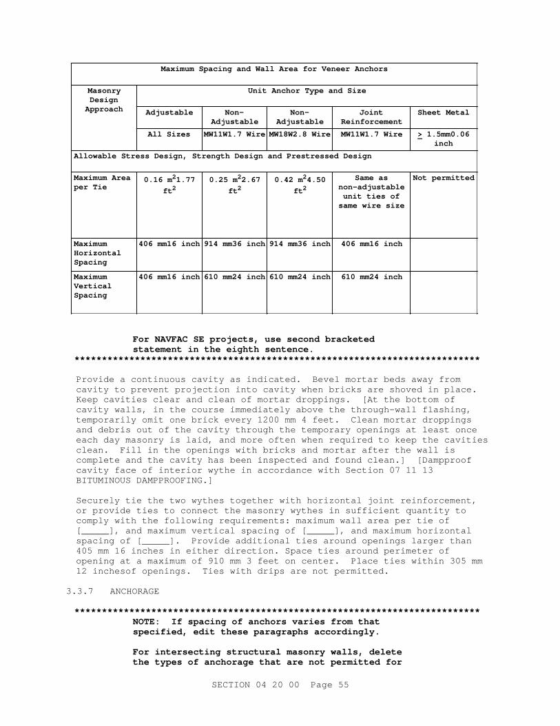
Maxi mum Spaci ng and Wal l Ar ea f or Veneer Anchor s
MasonryDesign
Approach
Uni t Anchor Type and Si ze
Adjustable Non-Adjustable
Non-Adjustable
JointReinforcement
Sheet Met al
Al l Si zes MW11W1. 7 Wi r e MW18W2. 8 Wi r e MW11W1. 7 Wi r e > 1. 5mm0. 06inch
Al l owabl e St r ess Desi gn, St r engt h Desi gn and Pr est r essed Desi gn
Maxi mum Ar ea per Ti e
0. 16 m21.77
ft 20. 25 m22.67
ft 20. 42 m24.50
ft 2
Same asnon-adjustable
uni t t i es ofsame wi r e s i ze
Not per mi t t ed
Maximum Horizontal Spacing
406 mm16 i nch 914 mm36 i nch 914 mm36 i nch 406 mm16 i nch
Maximum Vertical Spacing
406 mm16 i nch 610 mm24 i nch 610 mm24 i nch 610 mm24 i nch
For NAVFAC SE pr oj ect s, use second br acket ed st at ement i n t he ei ght h sent ence.
**************************************************************************
Pr ovi de a cont i nuous cavi t y as i ndi cat ed. Bevel mor t ar beds away f r om cavi t y t o pr event pr oj ect i on i nt o cavi t y when br i cks ar e shoved i n pl ace. Keep cavi t i es c l ear and cl ean of mor t ar dr oppi ngs. [ At t he bot t om of cavi t y wal l s, i n t he cour se i mmedi at el y above t he t hr ough- wal l f l ashi ng, t empor ar i l y omi t one br i ck ever y 1200 mm 4 f eet . Cl ean mor t ar dr oppi ngs and debr i s out of t he cavi t y t hr ough t he t empor ar y openi ngs at l east once each day masonr y i s l ai d, and mor e of t en when r equi r ed t o keep t he cavi t i es c l ean. Fi l l i n t he openi ngs wi t h br i cks and mor t ar af t er t he wal l i s compl et e and t he cavi t y has been i nspect ed and f ound cl ean. ] [ Damppr oof cavi t y f ace of i nt er i or wyt he i n accor dance wi t h Sect i on 07 11 13 BI TUMI NOUS DAMPPROOFI NG. ]
Secur el y t i e t he t wo wyt hes t oget her wi t h hor i zont al j oi nt r ei nf or cement , or pr ovi de t i es t o connect t he masonr y wyt hes i n suf f i c i ent quant i t y t o compl y wi t h t he f ol l owi ng r equi r ement s: maxi mum wal l ar ea per t i e of [ _____] , and maxi mum ver t i cal spaci ng of [ _____] , and maxi mum hor i zont al spaci ng of [ _____] . Pr ovi de addi t i onal t i es ar ound openi ngs l ar ger t han 405 mm 16 i nches i n ei t her di r ect i on. Space t i es ar ound per i met er of openi ng at a maxi mum of 910 mm 3 f eet on cent er . Pl ace t i es wi t hi n 305 mm 12 i nchesof openi ngs. Ti es wi t h dr i ps ar e not per mi t t ed.
3. 3. 7 ANCHORAGE
**************************************************************************NOTE: I f spaci ng of anchor s var i es f r om t hat speci f i ed, edi t t hese par agr aphs accor di ngl y.
For i nt er sect i ng st r uct ur al masonr y wal l s, del et e t he t ypes of anchor age t hat ar e not per mi t t ed f or
SECTI ON 04 20 00 Page 55
t he pr oj ect .**************************************************************************
3. 3. 7. 1 Anchor age t o Concr et e
Anchor age of masonr y t o t he f ace of concr et e col umns, beams, or wal l s shal l be wi t h dovet ai l anchor s spaced not over 400 mm 16 i nches on cent er s ver t i cal l y and 600 mm 24 i nches on cent er hor i zont al l y .
3. 3. 7. 2 Anchor age t o St r uct ur al St eel
Masonr y shal l be anchor ed t o ver t i cal st r uct ur al s t eel f r ami ng wi t h adj ust abl e st eel wi r e anchor s spaced not over 400 mm 16 i nches on cent er s ver t i cal l y , and i f appl i cabl e, not over 600 mm 24 i nches on cent er s horizontally.
3. 3. 7. 3 Anchor age at I nt er sect i ng Wal l s
Pr ovi de wi r e mesh anchor s at maxi mum 400 mm 16 i nches spaci ng at i nt er sect i ons of i nt er i or non- bear i ng masonr y wal l s.
**************************************************************************NOTE: Det ai l s wi l l be shown on t he dr awi ngs whi ch i l l ust r at e cor ner s and i nt er sect i ons of st r uct ur al bond beam r ei nf or cement and f act or y- f or med j oi nt r ei nf or cement . When j oi nt r ei nf or cement i s not used, del et e pr ef abr i cat ed cor ner s or t ee pi eces.
**************************************************************************
Anchor st r uct ur al masonr y wal l s wi t h [ r ei nf or ced bond beams spaced no mor e t han [ _____] mm f eet on cent er ] [ hor i zont al j oi nt r ei nf or cement spaced no mor e t han [ _____] mm f eet on cent er ] [ over l appi ng masonr y uni t s] [ st r ap anchor s of mi ni mum si ze 6 mm 1/ 4 i nch x 38 mm 1- 1/ 2 i nch x 710 mm 28 i nches i ncl udi ng 50 mm 2 i nch) 90 degr ee bends at each end t o f or m U or Z shape at maxi mum spaci ng 1220 mm 48 i nches, gr out ed i nt o t he wal l ] , unl ess t he dr awi ngs i ndi cat e a movement j oi nt at t he i nt er sect i on.
3. 3. 8 Lintels
3. 3. 8. 1 Masonr y Li nt el s
Const r uct masonr y l i nt el s wi t h l i nt el uni t s f i l l ed sol i d wi t h gr out i n al l cour ses and r ei nf or ced wi t h a mi ni mum of t wo No. 4 bar s i n t he bot t om cour se unl ess ot her wi se i ndi cat ed. Ext end l i nt el r ei nf or cement beyond each si de of masonr y openi ng 40 bar di amet er s or 600 mm 24 i nches, whi chever i s gr eat er . Suppor t r ei nf or c i ng bar s i n pl ace pr i or t o gr out i ng and l ocat e 13 mm 1/ 2 i nch above t he bot t om i nsi de sur f ace of t he l i nt el uni t .
3. 3. 8. 2 Pr ecast Concr et e and St eel Li nt el s
Pr ovi de pr ecast concr et e and st eel l i nt el s as shown on t he Dr awi ngs. Set l i nt el s i n a f ul l bed of mor t ar wi t h f aces pl umb and t r ue. Pr ovi de st eel and pr ecast l i nt el s wi t h a mi ni mum bear i ng l engt h of 200 mm 8 i nches unl ess ot her wi se i ndi cat ed. I n par t i al l y gr out ed masonr y, pr ovi de f ul l y gr out ed uni t s under t he f ul l l i nt el bear i ng l engt h, unl ess ot her wi se i ndi cat ed.
3. 3. 9 Si l l s and Copi ngs
**************************************************************************
SECTI ON 04 20 00 Page 56

NOTE: Copi ng and si l l s exceedi ng 1200 mm 4 f eet shoul d be mechani cal l y anchor ed and det ai l ed on t he pr oj ect dr awi ngs. Wher e such anchor s penet r at e t hr ough- wal l f l ashi ng, seal i ng of t he penet r at i on shoul d be r equi r ed.
**************************************************************************
Set s i l l s and copi ngs i n a f ul l bed of mor t ar wi t h f aces pl umb and t r ue. Sl ope si l l s and copi ngs t o dr ai n wat er . Mechani cal l y anchor copi ngs and si l l s l onger t han 1200 mm 4 f eet as i ndi cat ed.
3. 4 INSTALLATION
3. 4. 1 Bar Rei nf or cement I nst al l at i on
3. 4. 1. 1 Preparation
Submi t det ai l dr awi ngs showi ng bar spl i ce l ocat i ons. I dent i f y bent bar s on a bendi ng di agr am and r ef er ence and l ocat e such bar s on t he dr awi ngs. Show wal l di mensi ons, bar c l ear ances, and wal l openi ngs. Ut i l i ze bendi ng det ai l s t hat conf or m t o t he r equi r ement s of ACI SP- 66. No appr oval wi l l be gi ven t o t he shop dr awi ngs unt i l t he Cont r act or cer t i f i es t hat al l openi ngs, i ncl udi ng t hose f or mechani cal and el ect r i cal ser vi ce, ar e shown. I f , dur i ng const r uct i on, addi t i onal masonr y openi ngs ar e r equi r ed, r esubmi t t he appr oved shop dr awi ngs wi t h t he addi t i onal openi ngs shown al ong wi t h t he pr oposed changes. Cl ear l y hi ghl i ght l ocat i on of t hese addi t i onal openi ngs. Pr ovi de wal l el evat i on dr awi ngs wi t h mi ni mum scal e of 1 t o 50 1/ 4 i nch per f oot . Submi t dr awi ngs i ncl udi ng pl ans, el evat i ons, and det ai l s of wal l r ei nf or cement ; det ai l s of r ei nf or c i ng bar s at cor ner s and wal l i nt er sect i ons; of f set s; t ops, bot t oms, and ends of wal l s; cont r ol and expansi on j oi nt s; l i nt el s; and wal l openi ngs.
Cl ean r ei nf or cement of l oose, f l aky r ust , scal e, gr ease, mor t ar , gr out , and ot her coat i ngs t hat mi ght dest r oy or r educe i t s bond pr i or t o pl aci ng gr out . Do not use bar s wi t h k i nks or bends not shown on t he appr oved shop dr awi ngs. Pl ace r ei nf or cement pr i or t o gr out i ng. Unl ess ot her wi se i ndi cat ed, ext end ver t i cal wal l r ei nf or cement t o wi t hi n 50 mm 2 i nches of t ops of wal l s.
3. 4. 1. 2 Posi t i oni ng Bar s
**************************************************************************NOTE: Posi t i oni ng of bar s wi l l be shown on t he drawings.
**************************************************************************
a. Accur at el y pl ace ver t i cal bar s wi t hi n t he cel l s at t he posi t i ons i ndi cat ed on t he dr awi ngs. A mi ni mum cl ear ance of 13 mm 1/ 2 i nch shal l be mai nt ai ned bet ween t he bar s and masonr y uni t s. Pr ovi de mi ni mum cl ear ance bet ween par al l el bar s of 13 mm 1/ 2 i nch bet ween t he bar s and masonr y uni t s f or coar se gr out and a mi ni mum cl ear ance of 6 mm 1/ 4 i nch bet ween t he bar s and masonr y uni t s f or f i ne gr out . Pr ovi de mi ni mum cl ear ance bet ween par al l el bar s of 25 mm 1 i nch or one di amet er of t he r ei nf or cement , whi chever i s gr eat er . Ver t i cal r ei nf or cement may be hel d i n pl ace usi ng bar posi t i oner s l ocat ed near t he ends of each bar and at i nt er medi at e i nt er val s of not mor e t han 192 di amet er s of t he r ei nf or cement or by ot her means t o pr event di spl acement beyond per mi t t ed t ol er ances. As masonr y wor k pr ogr esses, secur e ver t i cal r ei nf or cement t o pr event di spl acement beyond al l owabl e t ol er ances.
SECTI ON 04 20 00 Page 57
b. Wi r e col umn and pi l ast er l at er al t i es i n posi t i on ar ound t he ver t i cal r ei nf or c i ng bar s. Pl ace l at er al t i es i n cont act wi t h t he ver t i cal r ei nf or cement and do not pl ace i n hor i zont al mor t ar bed j oi nt s.
c. Posi t i on hor i zont al r ei nf or c i ng bar s as i ndi cat ed. St agger spl i ces i n adj acent hor i zont al bar s, unl ess ot her wi se i ndi cat ed.
d. For m spl i ces by l appi ng bar s as i ndi cat ed. Do not cut , bend or el i mi nat e r ei nf or c i ng bar s. Foundat i on dowel bar s may be f i el d- bent when per mi t t ed by TMS MSJC.
3. 4. 1. 3 Spl i ces of Bar Rei nf or cement
**************************************************************************NOTE: The desi gner must det er mi ne t he r equi r ed l ap spl i ce l engt hs and i ndi cat e on t he pr oj ect document s. Requi r ed l ap spl i ce l engt h may var y dependi ng upon whet her t he masonr y i s desi gned by al l owabl e st r ess or st r engt h.
**************************************************************************
Lap spl i ce r ei nf or c i ng bar s as i ndi cat ed. When used, pr ovi de wel ded or mechani cal connect i ons t hat devel op at l east 125 per cent of t he speci f i ed y i el d st r engt h of t he r ei nf or cement .
3. 4. 2 Pl aci ng Gr out
**************************************************************************NOTE: Mechani cal consol i dat i on of sel f - consol i dat i ng gr out shoul d not be per f or med because i t may cause segr egat i on. When pl aci ng sel f - consol i dat i ng gr out , t he pr oper t i es l i s t ed i n ASTM C476 shoul d be ver i f i ed.
**************************************************************************
3. 4. 2. 1 General
Fi l l cel l s cont ai ni ng r ei nf or c i ng bar s wi t h gr out . Sol i dl y gr out hol l ow masonr y uni t s i n wal l s or par t i t i ons suppor t i ng pl umbi ng, heat i ng, or ot her mechani cal f i x t ur es, voi ds at door and wi ndow j ambs, and ot her i ndi cat ed spaces. Sol i dl y gr out cel l s under l i nt el bear i ngs on each si de of openi ngs f or f ul l hei ght of openi ngs. Sol i dl y gr out wal l s bel ow gr ade, l i nt el s, and bond beams. Uni t s ot her t han open end uni t s may r equi r e gr out i ng each cour se t o pr ecl ude voi ds i n t he uni t s.
Di scar d s i t e- mi xed gr out t hat i s not pl aced wi t hi n 1- 1/ 2 hour s af t er wat er i s f i r st added t o t he bat ch or when t he speci f i ed s l ump i s not met wi t hout addi ng wat er af t er i ni t i al mi x i ng. Di scar d r eady- mi xed gr out t hat does not meet t he speci f i ed s l ump wi t hout addi ng wat er ot her t han wat er t hat was added at t he t i me of i ni t i al di schar ge. Al l ow suf f i c i ent t i me bet ween gr out l i f t s t o pr ecl ude di spl acement or cr acki ng of f ace shel l s of masonr y uni t s. Pr ovi de a gr out shear key bet ween l i f t s when gr out i ng i s del ayed and t he l ower l i f t l oses pl ast i c i t y. I f bl owout s, f l owout s, mi sal i gnment , or cr acki ng of f ace shel l s shoul d occur dur i ng const r uct i on, t ear down t he wal l and r ebui l d.
SECTI ON 04 20 00 Page 58

3. 4. 2. 2 Ver t i cal Gr out Bar r i er s f or Mul t i - Wyt he Composi t e Wal l s
I n mul t i - wyt he composi t e wal l s, pr ovi de gr out bar r i er s i n t he col l ar j oi n not mor e t han 9 m 30 f eet apar t , or as r equi r ed, t o l i mi t t he hor i zont al f l ow of gr out f or each pour .
3. 4. 2. 3 Hor i zont al Gr out Bar r i er s
Embed hor i zont al gr out bar r i er s i n mor t ar bel ow cel l s of hol l ow uni t s r ecei v i ng gr out .
3. 4. 2. 4 Gr out Hol es and Cl eanout s
3. 4. 2. 4. 1 Gr out Hol es
Pr ovi de gr out i ng hol es i n s l abs, spandr el beams, and ot her i n- pl ace over head const r uct i on. Locat e hol es over ver t i cal r ei nf or c i ng bar s or as r equi r ed t o f aci l i t at e gr out f i l l i n bond beams. Pr ovi de addi t i onal openi ngs spaced not mor e t han 400 mm 16 i nches on cent er s wher e gr out i ng of hol l ow uni t masonr y i s i ndi cat ed. Fom such openi ngs not l ess t han 100 mm 4 i nches i n di amet er or 75 by 100 mm 3 by 4 i nches i n hor i zont al di mensi ons. Upon compl et i on of gr out i ng oper at i ons, pl ug and f i ni sh gr out i ng hol es t o mat ch sur r oundi ng sur f aces.
3. 4. 2. 4. 2 Cl eanout s f or Hol l ow Uni t Masonr y Const r uct i on
For hol l ow masonr y uni t s. pr ovi de c l eanout hol es at t he bot t om of ever y gr out pour i n cor es cont ai ni ng ver t i cal r ei nf or cement when t he hei ght of t he gr out pour exceeds 1. 6 m 5 f eet 4 i nches. Wher e al l cel l s ar e t o be gr out ed, const r uct c l eanout cour ses usi ng bond beam uni t s i n an i nver t ed posi t i on t o per mi t c l eani ng of al l cel l s . Pr ovi de c l eanout hol es at a maxi mum spaci ng of 800 mm 32 i nches wher e al l cel l s ar e t o be f i l l ed wi t h grout.
Est abl i sh a new ser i es of c l eanout s i f gr out i ng oper at i ons ar e st opped f or mor e t han 4 hour s. Pr ovi de c l eanout s not l ess t han 75 by 75 mm 3 by 3 i nch by cut t i ng openi ngs i n one f ace shel l . Manuf act ur er ' s st andar d cut out uni t s may be used at t he Cont r act or ' s opt i on. Do not c l eanout hol es unt i l masonr y wor k, r ei nf or cement , and f i nal c l eani ng of t he gr out spaces have been compl et ed and i nspect ed. For wal l s whi ch wi l l be exposed t o v i ew, c l ose c l eanout hol es i n an appr oved manner t o mat ch sur r oundi ng masonr y.
3. 4. 2. 4. 3 Cl eanout s f or Mul t i - Wyt he Composi t e Masonr y Const r uct i on
Pr ovi de c l eanout s f or const r uct i on of wal l s t hat i ncor por at e a gr out f i l l ed cavi t y bet ween sol i d masonr y wyt hes, pr ovi de c l eanout s at t he bot t om of ever y pour by omi t t i ng ever y ot her masonr y uni t f r om one wyt he. Est abl i sh a new ser i es of c l eanout s i f gr out i ng oper at i ons ar e st opped f or mor e t han 4 hour s. Do not pl ug c l eanout hol es unt i l masonr y wor k, r ei nf or cement , and f i nal c l eani ng of t he gr out spaces have been compl et ed and i nspect ed. For wal l s whi ch wi l l be exposed t o v i ew, c l ose c l eanout hol es i n an appr oved manner t o mat ch sur r oundi ng masonr y.
3. 4. 2. 5 Gr out Pl acement
**************************************************************************NOTE: The r equi r ement s l i s t ed ar e f or nor mal gr out i ng pr ocedur es. Ot her opt i ons, such as hi gher gr out l i f t s , hi gher gr out pour s, or al t er nat e
SECTI ON 04 20 00 Page 59
met hods of keepi ng t he gr out space cl ean, may be accept abl e i f pr oven t hr ough t he pr ocess of const r uct i ng and exami ni ng a gr out demonst r at i on panel.
A gr out pour i s t he t ot al hei ght of masonr y t o be gr out ed pr i or t o er ect i on of addi t i onal masonr y. A gr out l i f t i s an i ncr ement of gr out pl acement wi t hi n a gr out pour . A gr out pour i s f i l l ed by one or mor e l i f t s of gr out . Maxi mum gr out pour hei ght i s based on gr out t ype ( f i ne or coar se) and di mensi ons of gr out space, per TMS MSJC Tabl e 7. Fi ne gr out has sand as t he onl y aggr egat e whi l e coar se gr out uses bot h sand and pea gr avel up t o 10 mm 3/ 8 i nch di amet er . Coar se gr out i s pr ef er r ed when gr out wi l l be pl aced i n r el at i vel y l ar ge cr oss- sect i onal ar eas because shr i nkage of t he gr out i s r educed.
By f ol l owi ng t he TMS gr out pour and l i f t r ecommendat i ons and usi ng gr out of t he pr oper consi st ency, gr out pl acement occur s at a r at e t hat does not cause di spl acement of masonr y due t o hydr ost at i c pr essur e of gr out . Sel f - consol i dat i ng gr out ( SCG) at t ai ns i t s f l ow pr i mar i l y f r om super pl ast i c i z i ng admi xt ur es, not wat er , so i t exer t s a l ower hydr ost at i c pr essur e t han convent i onal gr out dur i ng pl acement . Gr out shoul d be pl aced as r api dl y as pr act i cal by met hods t hat do not cause segr egat i on and t hat mi ni mi ze spl at t er on r ei nf or cement and sur r oundi ng masonr y. Convent i onal gr out l i f t s shoul d be consol i dat ed ( and r econsol i dat ed) by mechani cal v i br at i on bef or e t he next l i f t i s pl aced. SCG does not need t o be consolidated.
**************************************************************************
A gr out pour i s t he t ot al hei ght of masonr y t o be gr out ed pr i or t o er ect i on of addi t i onal masonr y. A gr out l i f t i s an i ncr ement of gr out pl acement wi t hi n a gr out pour . A gr out pour i s f i l l ed by one or mor e l i f t s of gr out .
a. Lay masonr y t o t he t op of a pour per mi t t ed by TMS MSJC Tabl e 7, based on t he s i ze of t he gr out space and t he t ype of gr out . Pr i or t o gr out i ng, r emove masonr y pr ot r usi ons t hat ext end 13 mm 1/ 2 i nch or mor e i nt o cel l s or spaces t o be gr out ed. Pr ovi de gr out hol es and cl eanout s i n accor dance wi t h par agr aph GROUT HOLES AND CLEANOUTS above when t he gr out pour hei ght exceeds 1. 6 m 5 f eet 4 i nches. Hol d r ei nf or cement , bol t s, and embedded connect i ons r i gi dl y i n posi t i on bef or e gr out i ng i s st ar t ed. Do not pr ewet concr et e masonr y uni t s.
b. Pl ace gr out usi ng a hand bucket , concr et e hopper , or gr out pump t o f i l l t he gr out space wi t hout segr egat i on of aggr egat e. Oper at e gr out pumps t o pr oduce a cont i nuous st r eam of gr out wi t hout ai r pocket s, segr egat i on, or cont ami nat i on.
c. I f t he masonr y has cur ed at l east 4 hour s, gr out s l ump i s mai nt ai ned bet ween 250 and 275 mm 10 t o 11 i nches, and no i nt er medi at e r ei nf or ced bond beams ar e pl aced bet ween t he t op and bot t om of t he pour hei ght , pl ace convent i onal gr out i n l i f t s not exceedi ng 3. 9 m 12 f eet 8 i nches. For t he same cur i ng and sl ump condi t i ons but wi t h i nt er medi at e bond
SECTI ON 04 20 00 Page 60

beams, l i mi t convent i onal gr out l i f t t o t he bot t om of t he l owest bond beam t hat i s mor e t han 1. 6 m 5 f eet 4 i nches above t he bot t om of t he l i f t , but do not exceed 3. 9 m 12 f eet 8 i nches. I f masonr y has not cur ed at l east 4 hour s or gr out s l ump i s not mai nt ai ned bet ween 250 and 275 mm 10 t o 11 i nches, pl ace convent i onal gr out i n l i f t s not exceedi ng 1. 6 m 5 f eet 4 i nches.
d. Consol i dat e convent i onal gr out l i f t and r econsol i dat e af t er i ni t i al set t l ement bef or e pl aci ng next l i f t . For gr out pour s t hat ar e 300 mm 12 i nches or l ess i n hei ght , consol i dat e and r econsol i dat e gr out by mechani cal v i br at i on or puddl i ng. For gr out pour s t hat ar e gr eat er t han 300 mm 12 i nches i n hei ght , consol i dat e and r econsol i dat e gr out by mechani cal v i br at i on. Appl y v i br at or s at uni f or ml y spaced poi nt s not f ur t her apar t t han t he v i s i bl e ef f ect i veness of t he machi ne. Li mi t dur at i on of v i br at i on t o t i me necessar y t o pr oduce sat i sf act or y consol i dat i on wi t hout causi ng segr egat i on. I f pr evi ous l i f t i s not per mi t t ed t o set , di p v i br at or i nt o pr evi ous l i f t . Do not i nser t v i br at or s i nt o l ower l i f t s t hat ar e i n a semi - sol i di f i ed st at e. I f l ower l i f t set s pr i or t o pl acement of subsequent l i f t , f or m a gr out key by t er mi nat i ng gr out a mi ni mum of 38 mm 1- 1/ 2 i nch bel ow a mor t ar j oi nt . Vi br at e each ver t i cal cel l cont ai ni ng r ei nf or cement i n par t i al l y gr out ed masonr y. Do not f or m gr out keys wi t hi n beams.
e. I f t he masonr y has cur ed 4 hour s, pl ace sel f - consol i dat i ng gr out ( SCG) i n l i f t s not exceedi ng t he pour hei ght . I f masonr y has not cur ed f or at l east 4 hour s, pl ace SCG i n l i f t s not exceedi ng 1. 6 m 5 f eet 4 i nches. Do not mechani cal l y consol i dat e sel f - consol i dat i ng gr out . Pl ace sel f - consol i dat i ng gr out i n accor dance wi t h manuf act ur er ' s recommendations.
f . Upon compl et i on of each day' s gr out i ng, r emove wast e mat er i al s and debr i s f r om t he equi pment , and di spose of out s i de t he masonr y.
3. 4. 3 Joi nt Rei nf or cement I nst al l at i on
**************************************************************************NOTE: Locat i on of hor i zont al j oi nt r ei nf or cement shoul d be shown on t he dr awi ngs wi t h t he maxi mum ver t i cal spaci ng nor mal l y bei ng 400 mm 16 i nches. A 150 mm 6 i nch l ap spl i ce l engt h i s suf f i c i ent f or j oi nt r ei nf or cement whose onl y pur pose i s shr i nkage cont r ol . Joi nt r ei nf or cement t hat i s used st r uct ur al l y may need l onger l ap spl i ces.
**************************************************************************
I nst al l j oi nt r ei nf or cement at 400 mm 16 i nches on cent er unl ess ot her wi se i ndi cat ed. Lap j oi nt r ei nf or cement not l ess t han [ 150] [ _____] mm [ 6] [ _____] i nches. I nst al l pr ef abr i cat ed sect i ons at cor ner s and wal l i nt er sect i ons. Pl ace t he l ongi t udi nal wi r es of j oi nt r ei nf or cement i n mor t ar beds t o pr ovi de not l ess t han 16 mm 5/ 8 i nch cover t o ei t her f ace of t he uni t .
3. 4. 4 Bond Beams
**************************************************************************NOTE: Bond beams t hat ar e cont i nuous over openi ngs wi l l be r ei nf or ced t o ser ve as l i nt el s.
Bond beams at f l oor l i nes and r oof s, wher e t he beam
SECTI ON 04 20 00 Page 61

act s as a t ensi on t i e f or t he di aphr agm, ar e t ypi cal l y r ei nf or ced cont i nuousl y t hr ough masonr y movement j oi nt s, and t he mor t ar i s r aked back and f i ni shed wi t h backer r od and seal ant . I nt er medi at e bond beams ar e t ypi cal l y det ai l ed wi t h t he r ei nf or cement i nt er r upt ed, but dowel ed, at cont r ol j oi nt s and agai n f i ni shed wi t h r aked back mor t ar , backer r od and seal ant .
I nt er i or cont r ol j oi nt s ar e r aked t o weaken t he j oi nt t o f ocus cr acks i n t he cont r ol j oi nt and caul ked so t hat 1) cr acks don' t show and 2) pr ovi de a second l i ne of def ense shoul d moi st ur e t r y t o t r avel t hr ough t he cr acks i n t he cont r ol j oi nt .
**************************************************************************
Rei nf or ce and gr out bond beams as i ndi cat ed and as descr i bed i n par agr aphs above. I nst al l gr out bar r i er s under bond beam uni t s t o r et ai n t he gr out as r equi r ed, unl ess wal l i s f ul l y gr out ed or sol i d bot t om uni t s ar e used. For hi gh l i f t gr out i ng i n par t i al l y gr out ed masonr y, pr ovi de gr out r et ai ni ng mat er i al on t he t op of bond beams t o pr event upwar d f l ow of gr out . Ensur e t hat r ei nf or cement i s cont i nuous, i ncl udi ng ar ound cor ner s, except t hr ough cont r ol j oi nt s or expansi on j oi nt s, unl ess ot her wi se i ndi cat ed.
3. 4. 5 Fl ashi ng and Weeps
**************************************************************************NOTE: Locat e weeps and vent i l at or s t o ensur e t hat i n sever e weat her , wi nd dr i ven wat er does not ent er and dr ai n i nt o t he i nt er st i t i al space. I ndi cat e accept abl e l ocat i ons on dr awi ngs.
Weep spaci ng of 610 mm 24 i nches i s appr opr i at e f or open head j oi nt weeps and weep vent s. When smal l er weeps ar e used, t he spaci ng shoul d be r educed t o 406 mm 16 i nches.
**************************************************************************
I nst al l t hr ough- wal l f l ashi ng at obst r uct i ons i n t he cavi t y and wher e i ndi cat ed on Dr awi ngs. Ensur e cont i nui t y of t he f l ashi ng at l aps and i nsi de and out s i de cor ner s by spl i c i ng i n a manner appr oved by t he f l ashi ng manuf act ur er . Ensur e t hat t he t op edge of t he f l ashi ng i s seal ed by [ t ur ni ng t he f l ashi ng 13 mm 1/ 2 i nch i nt o t he mor t ar bed j oi nt of backup masonr y] [ at t achi ng a t er mi nat i on bar and appl y i ng compat i bl e seal ant at t he t op edge of t he t er mi nat i on bar ] [ l appi ng a mi ni mum of 150 mm 6 i nches under t he weat her r esi st i ve bar r i er ] [ secur i ng t he sheet met al f l ashi ng i nt o a r egl et cast i nt o t he concr et e backup] . Ter mi nat e t he hor i zont al l eg of t he f l ashi ng [ by ext endi ng t he sheet met al 13 mm 1/ 2 i nch beyond t he out s i de f ace of masonr y and t ur ni ng downwar d wi t h a hemmed dr i p] [ t er mi nat i ng t he f abr i c f l ashi ng 13 mm 1/ 2 i nch shor t of t he out s i de f ace of masonr y and adher i ng t he f l ashi ng t o a sheet met al dr i p edge] [ ext endi ng t he f abr i c f l ashi ng beyond t he out s i de f ace of masonr y and, when const r uct i on i s compl et e, cut t i ng t he f l ashi ng f l ush wi t h t he f ace of masonr y] . Pr ovi de seal ant bel ow t he dr i p edge of t hr ough- wal l f l ashi ng.
Wher ever t hr ough- wal l f l ashi ng occur s, pr ovi de weep hol es t o dr ai n f l ashi ng t o ext er i or at accept abl e l ocat i ons as i ndi cat ed. Pr ovi de weeps of [ open head j oi nt s] [ weep vent i l at or s] . Locat e weeps not mor e t han 600 mm 24 i nches on cent er s i n mor t ar j oi nt s of t he ext er i or wyt he di r ect l y on t he
SECTI ON 04 20 00 Page 62
hor i zont al l eg of t hr ough- wal l f l ashi ng over f oundat i ons, bond beams, and any ot her hor i zont al i nt er r upt i ons of t he cavi t y. Pl ace weep hol es per f ect l y hor i zont al or s l i ght l y cant ed downwar d t o encour age wat er dr ai nage out war d and not i nwar d. Ot her met hods may be used f or pr ovi di ng weeps when spaci ng i s r educed t o406 mm 16 i nches on cent er and appr oved by t he Cont r act i ng Of f i cer . Mai nt ai n weeps f r ee of mor t ar and ot her obstructions.
3. 5 APPLICATION
3. 5. 1 Insulation
**************************************************************************NOTE: Speci f y t api ng or seal i ng of boar d j oi nt s when t he i nsul at i on must act as t he ai r or vapor barrier.
**************************************************************************
I nsul at e cavi t y wal l s ( mul t i - wyt he noncomposi t e masonr y wal l s) , wher e shown, by i nst al l i ng boar d- t ype i nsul at i on on t he cavi t y s i de of t he i nner wyt he. Appl y boar d t ype i nsul at i on di r ect l y t o t he masonr y or t hr u- wal l f l ashi ng wi t h adhesi ve. Neat l y f i t i nsul at i on bet ween obst r uct i ons wi t hout i mpal i ng i nsul at i on on t i es or anchor s. Appl y i nsul at i on i n par al l el cour ses wi t h ver t i cal j oi nt s br eaki ng mi dway over t he cour se bel ow and i n moder at e cont act wi t h adj oi ni ng uni t s wi t hout f or c i ng. Cut t o f i t neat l y agai nst adj oi ni ng sur f aces. [ Tape or seal t he j oi nt s bet ween t he boar ds. ]
3. 5. 2 I nt er f ace wi t h Ot her Pr oduct s
**************************************************************************NOTE: Label " wet l ocat i ons" on t he dr awi ngs.
**************************************************************************
3. 5. 2. 1 Bui l t - I n I t ems
Fi l l spaces ar ound bui l t - i n i t ems wi t h mor t ar . Poi nt openi ngs ar ound f l ush- mount el ect r i cal out l et boxes i n wet l ocat i ons wi t h mor t ar . Embed anchor s, t i es, wal l pl ugs, accessor i es, f l ashi ng, pi pe s l eeves and ot her i t ems r equi r ed t o be bui l t - i n as t he masonr y wor k pr ogr esses. Ful l y embed anchor s, t i es and j oi nt r ei nf or cement i n t he mor t ar . Fi l l cel l s r ecei v i ng anchor bol t s and cel l s of t he f i r st cour se bel ow bear i ng pl at es wi t h gr out , unl ess ot her wi se i ndi cat ed.
3. 5. 2. 2 Door and Wi ndow Fr ame Joi nt s
On t he exposed i nt er i or and ext er i or s i des of ext er i or f r ames, r ake j oi nt s bet ween f r ames and abut t i ng masonr y wal l s t o a dept h of 10 mm 3/ 8 i nch.
3. 5. 2. 3 Bear i ng Pl at es
**************************************************************************NOTE: The bear i ng det ai l s must be shown on t he dr awi ngs. The t her mal ef f ect s must be consi der ed f or st eel beams bear i ng on masonr y t o pr event cr acki ng of masonr y wal l s due t o t her mal expansi on of st eel f r ami ng member s.
**************************************************************************
Set bear i ng pl at es f or beams, j oi st s, j oi st gi r der s and si mi l ar st r uct ur al
SECTI ON 04 20 00 Page 63
member s t o t he pr oper l i ne and el evat i on wi t h damp- pack beddi ng mor t ar , except wher e non- shr i nk gr out i s i ndi cat ed. Pr ovi de beddi ng mor t ar and non- shr i nk gr out s speci f i ed i n Sect i on [ 03 30 00. 00 10 CAST- I N- PLACE CONCRETE] [ 03 30 00 CAST- I N- PLACE CONCRETE] .
3. 5. 3 Tolerances
Lay masonr y pl umb, t r ue t o l i ne, wi t h cour ses l evel wi t hi n t he t ol er ances of TMS MSJC, Ar t i c l e 3. 3 F.
3. 6 FI ELD QUALI TY CONTROL
3. 6. 1 Tests
3. 6. 1. 1 Fi el d Test i ng of Mor t ar
**************************************************************************NOTE: Fi el d t est i ng of mor t ar shoul d be l i mi t ed or avoi ded. Bet t er i nf or mat i on can be obt ai ned by obser vi ng mor t ar bat chi ng t o conf i r m t hat pr oper pr opor t i ons and mi xi ng pr ocedur es have been f ol l owed. When f i el d t est i ng i s r equi r ed, ver i f i cat i on of pr opor t i ons i s pr ef er r ed t o mor t ar compr essi ve st r engt h t est i ng. Resul t s ar e avai l abl e i n a mat t er of hour s r at her t han days or weeks. Pr opor t i ons of f r esh mor t ar s can be det er mi ned by r unni ng t he mor t ar aggr egat e r at i o t est of ASTM C780 Appendi x A4. Mor t ar compr essi ve st r engt h, t est ed i n accor dance wi t h ASTM C780 Appendi x 6, i s not r equi r ed or expect ed t o meet t he pr oper t y r equi r ement s of ASTM C270 Tabl e 2 and has mor e meani ngf ul compar i sons t o pr econst r uct i on t est val ues t o eval uat e consi st ency. Ther ef or e, when mor t ar i s t est ed f or compr essi ve st r engt h, t est i ng must be per f or med pr i or t o const r uct i on as wel l as dur i ng const r uct i on. Fr equency of t est i ng, i f any, depends on t he s i ze and compl exi t y of t he pr oj ect . Modi f y par agr aph bel ow t o advi se r equi r ed f r equency of t est i ng and t ype( s) of t est i ng r equi r ed.
**************************************************************************
Per f or m mor t ar t est i ng at t he f ol l owi ng f r equency: [ _____] t i mes per [ _____] . For each r equi r ed mor t ar t est , pr ovi de a mi ni mum of t hr ee mor t ar sampl es. Per f or m i ni t i al mor t ar t est i ng pr i or t o const r uct i on f or compar i son pur poses dur i ng const r uct i on.
Pr epar e and t est mor t ar sampl es f or mor t ar aggr egat e r at i o i n accor dance with ASTM C780 Appendi x A4. [ Pr epar e and t est mor t ar compr essi ve st r engt h speci mens i n accor dance wi t h ASTM C780 Appendi x A6. ]
3. 6. 1. 2 Fi el d Test i ng of Gr out
**************************************************************************NOTE: Fi el d t est i ng of gr out i nvol ves measur i ng t emper at ur e, s l ump of convent i onal gr out , s l ump f l ow of SCG, v i sual s t abi l i t y i ndex of SCG, and compr essi ve st r engt h. Fi el d t est i ng of gr out i s not r equi r ed when masonr y compr essi ve st r engt h i s ver i f i ed by t he pr i sm t est met hod.
SECTI ON 04 20 00 Page 64

Fr equency of t est i ng depends on t he s i ze and compl exi t y of t he pr oj ect . Mi ni mum r equi r ement s f or t est i ng f r equency ar e pr ovi ded i n TMS MSJC Tabl es 1. 19. 1, 1. 19. 2, and 1. 19. 3 dependi ng upon how t he masonr y i s desi gned ( pr escr i pt i ve or engi neer ed) and t he Ri sk Cat egor y of t he pr oj ect . Modi f y par agr aph bel ow t o advi se r equi r ed f r equency of t est i ng.
**************************************************************************
a. Per f or m gr out t est i ng at t he f ol l owi ng f r equency: [ _____] t i mes per [ _____] . For each r equi r ed gr out pr oper t y t o be eval uat ed, pr ovi de a mi ni mum of t hr ee speci mens.
b. Sampl e and t est convent i onal and sel f - consl i dat i ng gr out f or compr essi ve st r engt h and t emper at ur e i n accor dance wi t h ASTM C1019.
c. Eval uat e s l ump i n convent i onal gr out i n accor dance wi t h ASTM C1019.
d. Eval uat e s l ump f l ow and vi sual st abi l i t y i ndex of sel f - consol i dat i ng gr out i n accor dance wi t h ASTM C1611/ C1611M.
[ 3. 6. 1. 3 Cl ay Br i ck Ef f l or escence Test
**************************************************************************NOTE: Del et e t hi s par agr aph i n ar eas wher e ef f l or escence has not been a pr obl em. Ef f l or escence i s gener al l y t he r esul t of poor desi gn and det ai l i ng and/ or poor qual i t y of const r uct i on. Pr oper l y cover ed and/ or f l ashed wal l s wi t h a good dr ai nage and weep syst em ar e gener al l y f r ee of ef f l or escence. Ef f l or escence t est i ng i s gener al l y not r equi r ed.
**************************************************************************
Test c l ay br i ck t hat wi l l be exposed t o weat her i ng f or ef f l or escence i n accor dance wi t h ASTM C67. Schedul e t est s f ar enough i n advance of st ar t i ng masonr y wor k t o per mi t r et est i ng i f necessar y. Uni t s meet i ng t he def i ni t i on of " ef f l or esced" ar e subj ect t o r ej ect i on.
] [ 3. 6. 1. 4 Pr i sm Test s
**************************************************************************NOTE: Pr i sm t est i ng wi l l onl y be r equi r ed f or st r uct ur es r equi r i ng masonr y compr essi ve st r engt hs hi gher t han t hose i ndi cat ed by t he conser vat i ve val ues der i ved by t he Uni t St r engt h Met hod. When t he compr essi ve st r engt h of masonr y can be ver i f i ed by t he Uni t St r engt h met hod, pr i sm t est i ng nor mal l y wi l l not be r equi r ed. Del et e t hi s par agr aph when pr i sm t est i ng i s not r equi r ed. When pr i sm t est r esul t s ar e l ower t han t he speci f i ed compr essi ve st r engt h, handl i ng and t est i ng of t he pr i sm speci mens shoul d be r evi ewed f or compl i ance t o t he r equi r ement s cont ai ned i n t he ASTM st andar d.
I ndi cat e t he speci f i ed compr essi ve st r engt h of masonr y i n par agr aph SYSTEM DESCRI PTI ON or on t he Drawings.
SECTI ON 04 20 00 Page 65
**************************************************************************
Per f or m at l east one pr i sm t est sampl e f or each 465 squar e met er s 5, 000 squar e f eet of wal l but not l ess t han t hr ee such t est s f or any bui l di ng. Eval uat e t hr ee pr i sms i n each t est . Fabr i cat e, st or e, handl e, and t est pr i sms i n accor dance wi t h ASTM C1314.
Seven- day t est s may be used pr ovi ded t he r el at i onshi p bet ween t he 7- and 28- day st r engt hs of t he masonr y i s est abl i shed by t he t est s of t he mat er i al s used. I f t he compr essi ve st r engt h of any pr i sm f al l s bel ow t he speci f i ed val ue by mor e t han 3. 5 MPa 500 psi , t ake st eps t o assur e t hat t he l oad- car r y i ng capaci t y of t he st r uct ur e i s not j eopar di zed. I f t he l i kel i hood of l ow- st r engt h masonr y i s conf i r med and comput at i ons i ndi cat e t hat t he l oad- car r y i ng capaci t y may have been si gni f i cant l y r educed, t est s of cor es dr i l l ed, or pr i sms sawed, f r om t he ar ea i n quest i on may be r equi r ed. I n such case, t ake t hr ee speci mens f or each pr i sm t est mor e t han 3. 5 MPa 500 psi bel ow t he speci f i ed val ue. Masonr y i n t he ar ea i n quest i on wi l l be consi der ed st r uct ur al l y adequat e i f t he aver age compr essi ve st r engt h of t hr ee speci mens i s equal t o or exceeds t he speci f i ed val ue. Addi t i onal t est i ng of speci mens ext r act ed f r om l ocat i ons r epr esent ed by er r at i c cor e or pr i sm st r engt h t est r esul t s wi l l be per mi t t ed.
] 3. 6. 1. 5 Si ngl e- Wyt he Masonr y Wal l Wat er Penet r at i on Test
**************************************************************************NOTE: I ncl ude masonr y wal l wat er penet r at i on t est i ng onl y f or s i ngl e- wyt he masonr y wal l const r uct i ons wher e wal l wat er penet r at i on wi l l i mpai r mi ssi on- cr i t i cal oper at i ons, cr eat e an i mmedi at e saf et y hazar d, or have a det r i ment al i mpact on i nt er i or f i ni shes. Test i ng eval uat es t he assembl ed wal l t est panel and does not assur e compl i ant wal l const r uct i on i n t he f i el d. As an opt i on addi t i onal t est i ng may be per f or med on t he act ual wal l const r uct i on i n accor dance wi t h ASTM C1601.
**************************************************************************
Pr i or t o st ar t of f i el d const r uct i on of t he s i ngl e- wyt he concr et e masonr y wal l , per f or m masonr y wal l wat er penet r at i on t est on mock- up wal l assembl i es consi st i ng of t he i dent i cal desi gn, mat er i al s, mi x, and const r uct i on met hods as t he act ual wal l const r uct i on and i n accor dance wi t h ASTM E514/ E514M. Pr epar e a mi ni mum of t hr ee speci mens and cur e f or mi ni mum 28 days pr i or t o t est i ng. Const r uct panel s by t he same met hods, pr ocesses, and appl i cat i ons t o be used on t he pr oj ect ' s const r uct i on s i t e. Spr ay t est f or 6 hour s on each speci men. I f wat er i s v i s i bl e on back of t est panel s dur i ng t he t est and ar eas of dampness on t he backsi de of t he t est panel s do not exceed 25 per cent of t he wal l ar ea, t he panel s wi l l be consi der ed t o have passed. Dampness i s def i ned as any ar ea of sur f ace dar keni ng or di scol or at i on due t o moi st ur e penet r at i on or accumul at i on bel ow t he obser ved sur f ace.
Const r uct addi t i onal t est panel s f or each f ai l ed t est per f or med unt i l t hr ee t est panel s pass t he t est . Fact or s t hat can af f ect t est per f or mance i ncl ude mat er i al s, mi x i ng, and qual i t y of appl i cat i on and wor kmanshi p. Mat er i al s, mi x i ng, and met hods adj ust ment s may be necessar y i n or der t o pr ovi de const r uct i on t hat passes t he wat er penet r at i on t est . Document and r ecor d t he t est speci men const r uct i on mat er i al s and appl i cat i on and pr ovi de wr i t t en t est r epor t i n accor dance wi t h ASTM E514/ E514M, suppl ement ed by a
SECTI ON 04 20 00 Page 66

det ai l ed di scussi on of t he speci f i cs of t est panel const r uct i on, appl i cat i on met hods and pr ocesses used, qual i t y of const r uct i on, and any var i ances or devi at i ons t hat may have occur r ed bet ween t est panel s dur i ng t est panel const r uct i on. For f ai l ed t est panel s, i dent i f y i n t he suppl ement al r epor t t he var i ances, def i c i enci es or f l aws t hat cont r i but ed t o t est panel f ai l ur e and i t emi ze t he pr ecaut i ons t o be t aken i n f i el d const r uct i on of t he masonr y wal l t o pr event s i mi l ar def i c i enci es and assur e t he wal l const r uct i on r epl i cat es t est panel condi t i ons t hat pass t he wat er penet r at i on t est . Submi t t he compl et e, cer t i f i ed t est r epor t , i ncl udi ng suppl ement al r epor t , t o t he Cont r act i ng Of f i cer pr i or t o st ar t of s i ngl e- wyt he concr et e masonr y wal l const r uct i on. Si gni f i cant changes t o mat er i al s, pr opor t i ons, or const r uct i on t echni ques f r om t hose used i n t he passi ng wat er penet r at i on t est ar e gr ounds f or per f or mi ng new t est s, at t he di scr et i on of t he Cont r act i ng Of f i cer .
3. 6. 2 Speci al I nspect i on
**************************************************************************NOTE: The desi gner must i ndi cat e on t he dr awi ngs al l l ocat i ons and al l f eat ur es f or whi ch speci al i nspect i on and t est i ng i s r equi r ed. Thi s i ncl udes i ndi cat i ng t he l ocat i ons of al l s t r uct ur al component s and connect i ons r equi r i ng i nspect i on.
**************************************************************************
Per f or m speci al i nspect i ons and t est i ng i n accor dance wi t h Sect i on 01 45 35 SPECI AL I NSPECTI ONS.
3. 7 POI NTI NG AND CLEANI NG
**************************************************************************NOTE: Cl eani ng of masonr y usi ng wat er pr essur e may be necessar y, but t he pr essur e used shoul d be t he mi ni mum r equi r ed t o successf ul l y c l ean t he masonr y sur f ace. Sat ur at i ng t he masonr y wal l i n t he c l eani ng pr ocess shoul d be avoi ded.
**************************************************************************
Af t er mor t ar j oi nt s have at t ai ned t hei r i ni t i al set , but pr i or t o har deni ng, compl et el y r emove mor t ar and gr out daubs and spl ashi ngs f r om masonr y- uni t sur f aces t hat wi l l be exposed or pai nt ed. Bef or e compl et i on of t he wor k, r ake out def ect s i n j oi nt s of masonr y t o be exposed or pai nt ed, f i l l wi t h mor t ar , and t ool t o mat ch exi st i ng j oi nt s. I mmedi at el y af t er gr out wor k i s compl et ed, r emove scum and st ai ns t hat have per col at ed t hr ough t he masonr y wor k usi ng a l ow pr essur e st r eam of wat er and a st i f f br i st l ed br ush. Do not c l ean masonr y sur f aces, ot her t han r emovi ng excess sur f ace mor t ar , unt i l mor t ar i n j oi nt s has har dened. Leave masonr y sur f aces c l ean, f r ee of mor t ar daubs, di r t , s t ai n, and di scol or at i on, i ncl udi ng scum f r om cl eani ng oper at i ons, and wi t h t i ght mor t ar j oi nt s t hr oughout . Do not use met al t ool s and met al br ushes f or c l eani ng.
3. 7. 1 Dr y- Br ushi ng Concr et e Masonr y
Dr y br ush exposed concr et e masonr y sur f aces at t he end of each day' s wor k and af t er any r equi r ed poi nt i ng, usi ng st i f f - f i ber br i st l ed br ushes.
3. 7. 2 Cl ay Br i ck Sur f aces
Cl ean exposed cl ay br i ck masonr y sur f aces t o obt ai n sur f aces f r ee of st ai n,
SECTI ON 04 20 00 Page 67
di r t , mor t ar and gr out daubs, ef f l or escence, and di scol or at i on or scum f r om cl eani ng oper at i ons. Per f or m cl eani ng i n accor dance wi t h t he appr oved cl eani ng pr ocedur e demonst r at ed on t he mockup.
Af t er c l eani ng, exami ne t he sampl e panel of s i mi l ar mat er i al f or di scol or at i on or st ai n as a r esul t of c l eani ng. I f t he sampl e panel i s di scol or ed or st ai ned, change t he met hod of c l eani ng t o ensur e t hat t he masonr y sur f aces i n t he st r uct ur e wi l l not be adver sel y af f ect ed. Wat er - soak exposed masonr y sur f aces and t hen cl ean wi t h a pr opr i et ar y masonr y c l eani ng agent speci f i cal l y r ecommended f or t he col or and t ext ur e by t he c l ay br i ck manuf act ur er and manuf act ur er of t he c l eani ng pr oduct . Appl y t he sol ut i on wi t h st i f f f i ber br ushes, f ol l owed i mmedi at el y by t hor ough r i nsi ng wi t h c l ean wat er . Use pr opr i et ar y c l eani ng agent s i n conf or mance wi t h t he c l eani ng pr oduct manuf act ur er ' s pr i nt ed r ecommendat i ons. Remove ef f l or escence i n conf or mance wi t h t he br i ck manuf act ur er ' s r ecommendat i ons.
3. 8 CLOSE- OUT TAKE- BACK PROGRAM
**************************************************************************NOTE: Take- back pr ogr ams r ef er t o pr ogr ams i n whi ch t he pr oduct manuf act ur er " t akes- back" scr ap mat er i al and/ or packagi ng associ at ed wi t h i t s pr oduct .
**************************************************************************
Col l ect i nf or mat i on f r om manuf act ur er f or t ake- back pr ogr am opt i ons. Set asi de [ masonr y uni t s, f ul l and par t i al ] [ scr ap] [ packagi ng] [ _____] t o be r et ur ned t o manuf act ur er f or r ecycl i ng i nt o new pr oduct . When such a ser vi ce i s not avai l abl e, seek l ocal r ecycl er s t o r ecl ai m t he mat er i al s. Submi t document at i on t hat i ncl udes cont act i nf or mat i on, summar y of pr ocedur es, and t he l i mi t at i ons and condi t i ons appl i cabl e t o t he pr oj ect . I ndi cat e manuf act ur er ' s commi t ment t o r ecl ai m mat er i al s f or r ecycl i ng and/ or r euse.
3. 9 PROTECTION
**************************************************************************NOTE: Cover i ng masonr y wal l s i s r equi r ed f or pr ot ect i on f r om det r i ment al moi st ur e i nt r usi on, whi ch can r esul t i n ef f l or escence, or as r equi r ed by col d weat her masonr y const r uct i on pr ovi s i ons. I n cer t ai n geogr aphi cal ar eas, ver t i cal r ei nf or cement may be pl aced pr i or t o i nst al l at i on of masonr y uni t s, whi ch can si gni f i cant l y i nt er f er e wi t h cover i ng masonr y wal l s.
**************************************************************************
Pr ot ect f aci ng mat er i al s agai nst st ai ni ng. Cover t op of wal l s wi t h nonst ai ni ng wat er pr oof cover i ng or membr ane t o pr ot ect f r om moi st ur e i nt r usi on when wor k i s not i n pr ogr ess. Cont i nue cover i ng t he t op of t he unf i ni shed wal l s unt i l t he wal l i s wat er pr oof ed wi t h a compl et e r oof or par apet syst em. Ext end cover i ng a mi ni mum of 600 mm 2 f eet down on each si de of t he wal l and hol d secur el y i n pl ace. Bef or e st ar t i ng or r esumi ng wor k, c l ean t op sur f ace of masonr y i n pl ace of l oose mor t ar and f or ei gn material.
- - End of Sect i on - -
SECTI ON 04 20 00 Page 68