va 28 16 00 intrusion detection system - wbdg 28 16 00.pdfsection 28 16 00 intrusion detection...
TRANSCRIPT
10-11
28 16 00-1
SECTION 28 16 00 INTRUSION DETECTION SYSTEM
SPECS WRITER NOTE: Delete // ________ // if not applicable to project. Also delete any other item or paragraph not applicable in the section and renumber the paragraphs. Insert additional provisions as required for this project.
PART 1 – GENERAL
1.1 DESCRIPTION
A. Provide and install a complete Intrusion Detection System, hereinafter
referred to as IDS, as specified in this section.
B. This Section includes the following:
1. Intrusion detection with [hard-wired] [multiplexed], modular,
microprocessor-based controls, intrusion sensors and detection
devices, and communication links to perform monitoring, alarm, and
control functions.
2. Responsibility for integrating electronic and electrical systems and
equipment is specified in the following Sections, with Work
specified in this Section:
a. Division 08 Section "DOOR HARDWARE".
b. Division 14 Section "ELECTRIC TRACTION ELEVATORS".
c. Division 27 Section "INTERCOMMUNICATIONS AND PROGRAM SYSTEMS".
d. Division 28 Section "PHYSICAL ACCESS CONTROL".
e. Division 28 Section "FIRE DETECTION AND ALARM".
f. Division 28 Section "VIDEO SURVEILLANCE".
g. Division 32 Section "CHAIN LINK FENCES AND GATES".
C. Related Sections include the following:
1. Division 28 Section "VIDEO SURVEILLANCE" for closed-circuit
television cameras that are used as devices for video motion
detection.
2. Division 28 Section "CONDUCTORS AND CABLES FOR ELECTRONIC SAFETY AND
SECURITY" for cabling between central-station control units and
field-mounted devices and controllers.
1.2 RELATED WORK
SPECS WRITER NOTE: Delete any item or paragraph not applicable in the section.
A. Section 01 00 00 - GENERAL REQUIREMENTS. For General Requirements.
B. Section 07 84 00 - FIRESTOPPING. Requirements for firestopping
application and use.

10-11
28 16 00-2
C. Section 14 21 00 - ELECTRIC TRACTION ELEVATORS. Requirements for
elevators.
D. Section 14 24 00 - HYDRAULIC ELEVATORS. Requirements for elevators.
E. Section 10 14 00 - SIGNAGE. Requirements for labeling and signs.
F. Section 26 05 11 - REQUIREMENTS FOR ELECTRICAL INSTALLATIONS.
Requirements for connection of high voltage.
G. Section 26 05 21 - LOW VOLTAGE ELECTRICAL POWER CONDUCTORS AND CABLES
(600 VOLTS AND BELOW). Requirements for power cables.
H. Section 28 05 00 – COMMON WORK RESULTS FOR ELECTRONIC SAFETY AND
SECURITY. Requirements for general requirements that are common to more
than one section in Division 28.
I. Section 28 05 13 - CONDUCTORS AND CABLES FOR ELECTRONIC SAFETY AND
SECURITY. Requirements for conductors and cables.
J. Section 28 05 26 - GROUNDING AND BONDING FOR ELECTRONIC SAFETY AND
SECURITY. Requirements for grounding of equipment.
K. Section 28 05 28.33 - CONDUITS AND BACKBOXES FOR ELECTRONIC SAFETY AND
SECURITY. Requirements for infrastructure.
L. Section 28 08 00 - COMMISIONING OF ELECTRONIC SAFETY AND SECURITY.
Requirements for commissioning - systems readiness checklists, and
training.
M. Section 28 13 00 - PHYSICAL ACCESS CONTROL SYSTEMS (PACS). Requirements
for physical access control integration.
N. Section 28 13 16 - ACCESS CONTROL SYSTEM AND DATABASE MANAGEMENT.
Requirements for control and operation of all security systems.
O. Section 28 23 00 - VIDEO SURVEILLANCE. Requirements for security camera
systems.
P. Section 28 26 00 - ELECTRONIC PERSONAL PROTECTION SYSTEM (EPPS).
Requirements for emergency and interior communications.
Q. Section 28 31 00 - FIRE DETECTION AND ALARM. Requirements for
integration with fire detection and alarm system.
1.3 QUALITY ASSURANCE
A. The Contractor shall be responsible for providing, installing, and the
operation of the IDS as shown. The Contractor shall also provide
certification as required.
B. The security system shall be installed and tested to ensure all
components are fully compatible as a system and can be integrated with
all associated security subsystems, whether the security system is

10-11
28 16 00-3
stand-alone or a part of a complete Information Technology (IT)
computer network.
C. The Contractor or security sub-contractor shall be a licensed security
Contractor as required within the state or jurisdiction of where the
installation work is being conducted.
1.4 DEFINITIONS
A. Controller: An intelligent peripheral control unit that uses a
computer for controlling its operation. Where this term is presented
with an initial capital letter, this definition applies.
B. I/O: Input/Output.
C. Intrusion Zone: A space or area for which an intrusion must be
detected and uniquely identified, the sensor or group of sensors
assigned to perform the detection, and any interface equipment between
sensors and communication link to central-station control unit.
D. LED: Light-emitting diode.
E. NEC: National Electric Code
F. NEMA: National Electrical Manufacturers Association
G. NFPA: National Fire Protection Association
H. NRTL: Nationally Recognized Testing Laboratory.
I. SMS: Security Management System – A SMS is software that incorporates
multiple security subsystems (e.g., physical access control, intrusion
detection, closed circuit television, intercom) into a single platform
and graphical user interface.
J. PIR: Passive infrared.
K. RF: Radio frequency.
L. Standard Intruder: A person who weighs 45 kg (100 lb.) or less and
whose height is 1525 mm (60 in) or less; dressed in a long-sleeved
shirt, slacks, and shoes.
M. Standard-Intruder Movement: Any movement, such as walking, running,
crawling, rolling, or jumping, of a "standard intruder" in a protected
zone.
N. TCP/IP: Transport control protocol/Internet protocol incorporated into
Microsoft Windows.
O. UPS: Uninterruptible Power Supply
P. UTP: Unshielded Twisted Pair
1.5 SUBMITTALS
SPEC WRITER NOTE: Delete and/or amend all paragraphs and sub-paragraphs and information as needed to ensure that only

10-11
28 16 00-4
the documentation required is requested per the Request for Proposal (RFP).
//A. Refer to Section 28 05 00, Part1//
A. Submit below items in conjunction with Master Specification Sections 01
33 23, SHOP DRAWINGS, PRODUCT DATA, AND SAMPLES, and Section 02 41 00,
DEMOLITION.
B. Provide certificates of compliance with Section 1.3, Quality Assurance.
C. Provide a shop drawing and as-built design package in both electronic
format and on paper, minimum size 1220 x 1220 millimeters (48 x 48
inches); drawing submittals shall be per the established project
schedule.
D. Shop drawing and as-built packages shall include, but not be limited
to:
1. Index Sheet that shall:
a. Define each page of the design package to include facility name,
building name, floor, and sheet number.
b. Provide a list of all security abbreviations and symbols.
c. Reference all general notes that are utilized within the design
package.
d. Specification and scope of work pages for all security systems
that are applicable to the design package that will:
1) Outline all general and job specific work required within the
design package.
2) Provide a device identification table outlining device
Identification (ID) and use for all security systems equipment
utilized in the design package.
2. Drawing sheets that will be plotted on the individual floor plans or
site plans shall:
a. Include a title block as defined above.
b. Define the drawings scale in both standard and metric
measurements.
c. Provide device identification and location.
d. Address all signal and power conduit runs and sizes that are
associated with the design of the electronic security system and
other security elements (e.g., barriers, etc.).
e. Identify all pull box and conduit locations, sizes, and fill
capacities.
f. Address all general and drawing specific notes for a particular
drawing sheet.

10-11
28 16 00-5
3. A riser drawing for each applicable security subsystem shall:
a. Indicate the sequence of operation.
b. Relationship of integrated components on one diagram.
c. Include the number, size, identification, and maximum lengths of
interconnecting wires.
d. Wire/cable types shall be defined by a wire and cable schedule.
The schedule shall utilize a lettering system that will
correspond to the wire/cable it represents (example: A = 18 AWG/1
Pair Twisted, Unshielded). This schedule shall also provide the
manufacturer’s name and part number for the wire/cable being
installed.
4. A system drawing for each applicable security system shall:
a. Identify how all equipment within the system, from main panel to
device, shall be laid out and connected.
b. Provide full detail of all system components wiring from point-
to-point.
c. Identify wire types utilized for connection, interconnection with
associate security subsystems.
d. Show device locations that correspond to the floor plans.
e. All general and drawing specific notes shall be included with the
system drawings.
5. A schedule for all of the applicable security subsystems shall be
included. All schedules shall provide the following information:
a. Device ID.
b. Device Location (e.g. site, building, floor, room number,
location, and description).
c. Mounting type (e.g. flush, wall, surface, etc.).
d. Power supply or circuit breaker and power panel number.
e. In addition, for the IDS, provide the sensor ID, sensor type and
housing model number.
6. Detail and elevation drawings for all devices that define how they
were installed and mounted.
E. Shop drawing packages shall be reviewed by the Contractor along with a
VA representative to ensure all work has been clearly defined and
completed. All reviews shall be conducted in accordance with the
project schedule. There shall be four (4) stages to the review process:
1. 35 percent
2. 65 percent

10-11
28 16 00-6
3. 90 percent
4. 100 percent
F. Provide manufacturer security system product cut-sheets. Submit for
approval at least 30 days prior to commencement of formal testing, a
Security System Operational Test Plan. Include procedures for
operational testing of each component and security subsystem, to
include performance of an integrated system test.
G. Submit manufacture’s certification of Underwriters Laboratories, Inc.
(UL) listing as specified. Provide all maintenance and operating
manuals per the VA General Requirements, Section 01 00 00, GENERAL
REQUIREMENTS.
H. Completed System Readiness Checklists provided by the Commissioning
Agent and completed by the contractor, signed by a qualified technician
and dated on the date of completion, in accordance with the
requirements of Section 28 08 00 COMMISSIONING OF ELECTRONIC SAFETY AND
SECURITY SYSTEMS.
1.6 APPLICABLE PUBLICATIONS
A. The publications listed below (including amendments, addenda,
revisions, supplement, and errata) form a part of this specification to
the extent referenced. The publications are referenced in the text by
the basic designation only.
B. American National Standards Institute (ANSI)/Security Industry
Association (SIA):
PIR-01-00 .............. Passive Infrared Motion Detector Standard -
Features for Enhancing False Alarm Immunity
CP-01-00 ............... Control Panel Standard-Features for False Alarm
Reduction
C. Department of Justice American Disability Act (ADA)
28 CFR Part 36 ......... 2010 ADA Standards for Accessible Design
D. Federal Communications Commission (FCC):
(47 CFR 15) Part 15 .... Limitations on the Use of Wireless
Equipment/Systems
E. National Electrical Manufactures Association (NEMA):
250-08 ................. Enclosures for Electrical Equipment (1000 Volts
Maximum)
F. National Fire Protection Association (NFPA):
70-11 .................. National Electrical Code

10-11
28 16 00-7
731-08 ................. Standards for the Installation of Electric
Premises Security Systems
G. Underwriters Laboratories, Inc. (UL):
464-09 ................. Audible Signal Appliances
609-96 ................. Local Burglar Alarm Units and Systems
634-07 ................. Standards for Connectors with Burglar-Alarm
Systems
639-07 ................. Standards for Intrusion Detection Units
1037-09 ................ Standard for Anti-theft Alarms and Devices
1635-10 ................ Digital Alarm Communicator System Units
H. Uniform Federal Accessibility Standards (UFAS), 19841.
1.7 COORDINATION
A. Coordinate arrangement, mounting, and support of intrusion detection
system equipment:
1. To allow maximum possible headroom unless specific mounting heights
that reduce headroom are indicated.
2. To provide for ease of disconnecting the equipment with minimum
interference to other installations.
3. To allow right of way for piping and conduit installed at required
slope.
4. So connecting raceways, cables, wireways, cable trays, and busways
will be clear of obstructions and of the working and access space of
other equipment.
B. Coordinate installation of required supporting devices and set sleeves
in cast-in-place concrete, masonry walls, and other structural
components as they are constructed.
C. Coordinate location of access panels and doors for electronic safety
and security items that are behind finished surfaces or otherwise
concealed.
1.8 EQUIPMENT AND MATERIALS
A. General
1. All equipment associated within the IDS shall be rated for
continuous operation. Environmental conditions (i.e. temperature,
humidity, wind, and seismic activity) shall be taken under
consideration at each facility and site location prior to
installation of the equipment.
2. All equipment shall operate on a 120 or 240 volts alternating
current (VAC); 50 Hz or 60 Hz AC power system unless documented
10-11
28 16 00-8
otherwise in subsequent sections listed within this specification.
All equipment shall have a back-up source of power that will provide
a minimum of 96 hours of run time in the event of a loss of primary
power to the facility.
3. The system shall be designed, installed, and programmed in a manner
that will allow for ease of operation, programming, servicing,
maintenance, testing, and upgrading of the system.
4. All IDS components located in designated “HAZARDOUS ENVIRONMENT”
areas where fire or explosion could occur due to the presence of
natural gases or vapors, flammable liquids, combustible residue, or
ignitable fibers or debris, shall be rated Class II, Division I,
Group F, and installed in accordance with National Fire Protection
Association (NFPA) 70 National Electric Code, Chapter 5.
5. All equipment and materials for the system will be compatible to
ensure functional operation in accordance with requirements.
1.9 WARRANTY OF CONSTRUCTION.
A. Warrant IDS work subject to the Article “Warranty of Construction” of
FAR 52.246-21.
B. Demonstration and training shall be performed prior to system
acceptance.
PART 2 – PRODUCTS
SPEC WRITER NOTE: Delete or amend all paragraphs and sub-paragraphs as needed to ensure that only the equipment required per the Request for Proposal (RFP) is provided.
2.1 FUNCTIONAL DESCRIPTION OF SYSTEM
SPEC WRITER NOTE: Revise functional description to fit the project requirements.
A. Supervision: System components shall be continuously monitored for
normal, alarm, supervisory, and trouble conditions. Indicate
deviations from normal conditions at any location in system.
Indication includes identification of device or circuit in which
deviation has occurred and whether deviation is an alarm or
malfunction.
SPEC WRITER NOTE: Retain subparagraphs below if retaining option in paragraph above.

10-11
28 16 00-9
1. Alarm Signal: Display at central-station control unit and actuate
audible and visual alarm devices.
2. Trouble Condition Signal: Distinct from other signals, indicating
that system is not fully functional. Trouble signal shall indicate
system problems such as battery failure, open or shorted
transmission line conductors, or controller failure.
3. Supervisory Condition Signal: Distinct from other signals,
indicating an abnormal condition as specified for the particular
device or controller.
SPEC WRITER NOTE: Select one of the first two paragraphs below.
B. System Control: Central-station control unit shall directly monitor
intrusion detection units and connecting wiring.
C. System Control: Central-station control unit shall directly monitor
intrusion detection devices /, perimeter detection units,/ /,
controllers associated with perimeter detection units,/ and connecting
wiring in a multiplexed distributed control system or as part of a
network.
D. System shall automatically reboot program without error or loss of
status or alarm data after any system disturbance.
E. Operator Commands:
SPEC WRITER NOTE: Edit list below to suit Project. Coordinate with operator commands listed for "Central-Station Control Units" Article. Delete nonapplicable commands.
1. Help with System Operation: Display all commands available to
operator. Help command, followed by a specific command, shall
produce a short explanation of the purpose, use, and system reaction
to that command.
2. Acknowledge Alarm: To indicate that alarm message has been observed
by operator.
3. Place Protected Zone in Access: Disable all intrusion-alarm
circuits of a specific protected zone. Tamper circuits may not be
disabled by operator.
4. Place Protected Zone in Secure: Activate all intrusion-alarm
circuits of a protected zone.
5. Protected Zone Test: Initiate operational test of a specific
protected zone.
6. System Test: Initiate system-wide operational test.

10-11
28 16 00-10
7. Print Reports.
SPEC WRITER NOTE: Coordinate function in paragraph below with timing device specified in "Central-Station Control Units" Article.
F. Timed Control at Central-Station Control Unit: Allow automatically
timed "secure" and "access" functions of selected protected zones.
SPEC WRITER NOTE: Retain paragraph and subparagraphs below if alarm signals control lights, elevators, intercom, sound, or closed-circuit television components. Edit to suit Project design and systems integration specifications. Coordinate with Drawings.
G. Automatic Control of Related Systems: Alarm or supervisory signals
from certain intrusion detection devices control the following
functions in related systems:
1. Switch selected lights.
2. Shift elevator control to a different mode.
3. Open a signal path between certain intercommunication stations.
4. Shift sound system to "listening mode" and open a signal path to
certain system speakers.
5. Switch signal to selected monitor from closed-circuit television
camera in vicinity of sensor signaling an alarm.
SPEC WRITER NOTE: Delete paragraph below if no printer in system.
H. Printed Record of Events: Print a record of alarm, supervisory, and
trouble events on system printer. Sort and report by protected zone,
device, and function. When central-station control unit receives a
signal, print a report of alarm, supervisory, or trouble condition.
Report type of signal (alarm, supervisory, or trouble), protected zone
description, date, and time of occurrence. Differentiate alarm signals
from other indications. When system is reset, report reset event with
the same information concerning device, location, date, and time.
Commands shall initiate the reporting of a list of current alarm,
supervisory, and trouble conditions in system or a log of past events.
I. Response Time: 2 seconds between actuation of any alarm and its
indication at central-station control unit.
J. Circuit Supervision: Supervise all signal and data transmission lines,
links with other systems, and sensors from central-station control
unit. Indicate circuit and detection device faults with both protected
zone and trouble signals, sound a distinctive audible tone, and
10-11
28 16 00-11
illuminate an LED. Maximum permissible elapsed time between occurrence
of a trouble condition and indication at central-station control unit
is 20 seconds. Initiate an alarm in response to opening, closing,
shorting, or grounding of a signal or data transmission line.
SPEC WRITER NOTE: Delete paragraph below if not required for the Project. Coordinate with Drawings.
K. Programmed Secure-Access Control: System shall be programmable to
automatically change status of various combinations of protected zones
between secure and access conditions at scheduled times. Status
changes may be preset for repetitive, daily, and weekly; specially
scheduled operations may be preset up to a year in advance. Manual
secure-access control stations shall override programmed settings.
L. Manual Secure-Access Control: Coded entries at manual stations shall
change status of associated protected zone between secure and access
conditions.
2.2 SYSTEM COMPONENT REQUIREMENTS
SPEC WRITER NOTE: Retain first paragraph and subparagraph below if systems integration is required. If retaining, identify equipment and Section that specifies integrated system console.
A. Compatibility: Detection devices and their communication features,
connecting wiring, and central-station control unit shall be selected
and configured with accessories for full compatibility with the
following equipment:
1. Data Gathering Panel, Output Module, Input Module, 28 13 00 PHYSICAL
ACCESS CONTROL SYSTEM.
//2. List devices…//
B. Surge Protection: Protect components from voltage surges originating
external to equipment housing and entering through power,
communication, signal, control, or sensing leads. Include surge
protection for external wiring of each conductor entry connection to
components.
1. Minimum Protection for Power Lines 120 V and More: Auxiliary panel
suppressors complying with requirements in Division 26 Section
TRANSIENT-VOLTAGE SUPPRESSION FOR LOW-VOLTAGE ELECTRICAL POWER
CIRCUITS.
2. Minimum Protection for Communication, Signal, Control, and Low-
Voltage Power Lines: Comply with requirements in Division 26
Section TRANSIENT-VOLTAGE SUPPRESSION FOR LOW-VOLTAGE ELECTRICAL

10-11
28 16 00-12
POWER CIRCUITS as recommended by manufacturer for type of line being
protected.
C. Interference Protection: Components shall be unaffected by radiated
RFI and electrical induction of 15 V/m over a frequency range of 10 to
10,000 MHz and conducted interference signals up to 0.25-V RMS injected
into power supply lines at 10 to 10,000 MHz.
SPEC WRITER NOTE: Coordinate paragraph below with Drawings and detailed component Specifications.
D. Tamper Protection: Tamper switches on detection devices, controllers,
annunciators, pull boxes, junction boxes, cabinets, and other system
components shall initiate a tamper-alarm signal when unit is opened or
partially disassembled and when entering conductors are cut or
disconnected. Central-station control-unit alarm display shall
identify tamper alarms and indicate locations.
SPEC WRITER NOTES: Coordinate three paragraphs below with Drawings and with features listed in central-station control units and at central-station control unit. Delete items not in Project. Indicate features in a device schedule.
E. Self-Testing Devices: Automatically test themselves periodically, but
not less than once per hour, to verify normal device functioning and
alarm initiation capability. Devices transmit test failure to central-
station control unit.
F. Antimasking Devices: Automatically check operation continuously or at
intervals of a minute or less, and use signal-processing logic to
detect blocking, masking, jamming, tampering, or other operational
dysfunction. Devices transmit detection of operational dysfunction to
central-station control unit as an alarm signal.
G. Addressable Devices: Transmitter and receivers shall communicate
unique device identification and status reports to central-station
control unit.
SPEC WRITER NOTE: Delete paragraph below unless remotely adjustable detectors are used.
H. Remote-Controlled Devices: Individually and remotely adjustable for
sensitivity and individually monitored at central-station control unit
for calibration, sensitivity, and alarm condition.

10-11
28 16 00-13
2.3 ENCLOSURES
A. Interior Sensors: Enclosures that protect against dust, falling dirt,
and dripping noncorrosive liquids.
B. Interior Electronics: NEMA 250, Type 12.
C. Exterior Electronics: NEMA 250, Type 4X [fiberglass] [stainless
steel].
D. Corrosion Resistant: NEMA 250, Type 4X [PVC] [stainless steel].
E. Screw Covers: Where enclosures are accessible to inmates, secure with
security fasteners of type appropriate for enclosure.
2.5 EQUIPMENT ITEMS
A. General:
1. All requirements listed below are the minimum specifications that
need to be met in order to comply with the IDS.
2. All IDS sensors shall conform to UL 639, Intrusion Detection
Standard.
3. Ensure that IDS is fully integrated with other security subsystems
as required to include, but not limited to, the CCTV, PACS, EPPS,
and Physical Access Control System and Database Management. The IDS
provided shall not limit the expansion and growth capability to a
single manufacturer and shall allow modular expansion with minimal
equipment modifications.
B. IDS Components: The IDS shall consist of, but not be limited to, the
following components:
1. Control Panel
2. Exterior Detection Devices (Sensors)
3. Interior Detection Devices (Sensors)
4. Power Supply
5. Enclosures
2.6 CONTROL PANEL
A. The Control panel shall be the main point of programming, monitoring,
accessing, securing, and troubleshooting the IDS. Refer to American
National Standards Institute (ANSI) CP-01 Control Panel Standard-
Features for False Alarm Reduction.
B. The Control Panel shall provide a means of reporting alarms to an
Physical Access Control System and Database Management via a computer
interface or direct connection to an alarm control monitoring panel.
C. The Control panel shall utilize a Multifunctional Keypad, Input and
Output Modules for expansion of alarm zones, interfacing with

10-11
28 16 00-14
additional security subsystems, programming, monitoring and controlling
the IDS.
D. The Control panel shall meet or exceed the following minimum functional
requirements for programming outputs, system response, and user
interface:
1. Programming Outputs:
a. 2 Amps alarm power at 12 VDC
b. 1.4 Amps auxiliary power at 12 VDC
c. Four alarm output patterns
d. Programmable bell test
e. Programmable bell shut-off timer
2. System Response:
a. Selectable point response time
b. Cross point capability
c. Alarm verification
d. Watch mode
e. Scheduled events arm, disarm, bypass and un-bypass points,
control relays, and control authority levels
3. User Interface:
a. Supervises up to eight command points (e.g. Up to 16 unsupervised
keypads can be used)
b. Provides custom keypad text
c. Addresses full function command menu including custom functions
d. Allows user authority by defined area and 16-character name
e. Provides for 14 custom authority control levels allowing user’s
authority to change, add, delete pass codes, disarm, bypass
points, and start system tests.
4. The Control panel shall meet or exceed the following technical
characteristics:
Input Voltage via 110 VAC or 220 VAC Step-down Transformer
16 or 18 VAC
Operating Voltage 12 VDC
Output Voltage 12 VDC @ 2 A max
Direct Hardwire Zones 7
Partitions 8
Multifunctional Keypads 16 (2 per partition)
Communications Port RJ-11

10-11
28 16 00-15
E. A multifunctional keypad shall be utilized as a user interface for
arming, disarming, monitoring, troubleshooting, and programming the
alarm control panel.
F. Keypads shall have the following features:
1. Multiple function keypads suitable for remote mounting, no greater
than 1333 m (4000 ft), shall be provided from the control panel and
have a light emitting diode (LED) readout of alarm and trouble
conditions by zone.
2. An alphanumeric English language display, with keypad
programmability, and EE-PROM memory, shall also be provided.
3. Trouble alarm indicators shall be distinguishable from intrusion
alarms.
4. A minimum of four (4) zones selectable as entry and exit with
programmable time delay.
5. Complete system test activated capability at the keypad.
6. Capability for opening and closing reports to a remote monitoring
location.
7. Adjustable entry and exit delay times.
8. Capability for a minimum of two (2) multiple function keypads.
9. Capability to shunt or bypass selected interior zones while arming
perimeter protection and remaining interior zones.
10. Capability for a minimum of seven assignable pass-codes that are
keypad programmable from a suppressed master code.
11. The control panel shall have a communications port that will allow
for communications with a computer for programming, monitoring, and
troubleshooting purposes. The communications port will be, at a
minimum, and RJ-11 or better.
12. The control panel will have a systems success probability of 95% or
better, and shall include the following success considerations:
a. False Alarm: Shall not exceed one (1) false alarm per 30 days per
sensor zone.
b. Nuisance Alarm: Shall not exceed a rate of one (1) alarm per
seven (7) days per zone within the first 60 days after
installation and acceptance. Sensor adjustments will be made and
then shall not exceed one (1) alarm per 30 days.
13. The Control Panel will be able to detect either a line fault or
power loss for all supervised data cables.

10-11
28 16 00-16
a. Line Fault Detection: Communication links of the IDS shall have
an active mode for line fault detection. Fault isolation at the
systems level shall have the same geographic resolutions as
provided for intrusion detection. The line fault alarm shall be
clearly distinguishable from other alarms.
b. Power Loss Detection: Provide the capability to detect when
critical components experience temporary or permanent loss of
power and annunciate to clearly identify the component
experiencing power loss.
2.7 KEYPADS
A. Keypads shall meet or exceed the following technical characteristics:
Connections 4-wire flying lead for data and power
Operating Temperature 0°C to +50°C (+32°F to +122°F)
Display Window 8-point LED
Indicators: Illuminated keys Armed Status-LED
Point Status-LED
Command Mode-LED
Power-LED
Voltage Nominal 12 VDC
2.8 INPUT MODULE
A. An input module shall be utilized to connect additional detection
devices to the control panel. This module will meet or exceed the
following technical characteristics:
Operating Voltage 8.5 to 14.5 VDC Nominal
Zone Inputs Style A (Class B) Supervised
Operating Temperature 0 to 40 degrees C (32 to 140 degrees F)
2.9 OUTPUT MODULE
A. An output module shall be utilized to interface the control panel with
other security subsystems. The output module shall meet or exceed the
following technical characteristics:
Operating Voltage 8.5 to 14.5 VDC Nominal
Output Relays “Form C” Dry Relay Contracts
Relay Contact Rating 4A @ 24 VDC
4A @ 24 VAC

10-11
28 16 00-17
1A @ 70 VAC
Operating Temperature 0 to 40 degrees C F (32 to 140 degrees)
2.10 EXTERIOR DETECTION DEVICES (SENSORS)
A. The IDS shall consist of interior, exterior, and other detection
devices that are capable of:
1. Locating intrusions at individually protected asset areas or at an
individual portal;
2. Locating intrusions within a specific area of coverage;
3. Locating failures or tampering of individual sensors or components.
B. Audible annunciation shall meet UL 464 Audible Signal Appliance
requirements as well as other stated within this specification. IDS
shall provide and adjust for devices so that coverage is maximized in
the space or area it is installed in. For large areas where multiple
devices are required, ensure exterior device coverage is overlapping.
C. Detection sensitivity shall be set up to ensure maximum coverage of the
secure area is obtained while at the same time limiting excessive false
alarms due to the environment and impact of small animals. All
detection devices shall be anti-masking with exception of video motion
detection.
D. Dual sensor technology shall be used when possible. Sensor technology
shall not be of the same type that is easily defeated by a single
method. This will reduce the amount of false alarms.
E. Exterior sensors described in this section are intended for outdoor use
for perimeter and fence control monitoring purposes. Some sensors
described in the interior sensor section may be utilized that can
provide both outdoor and indoor protection.
F. External Sensors Environmental Characteristics:
Temperature -25°F - 140°F (-32°C - 60°C)
Pressure Sea Level to 15,000 ft. (4573m) above sea level
Solar Radiation Six (6) hrs. exposure at dry bulb temp. 120°F (60°C)
Rain Two (2) in. (50 mm) per hour
Humidity 5% - 95%
Fungus Components of non-fungus nutrient materials
Salt/fog Atmosphere 5% salinity
Snow loading 48 lbs per sq. ft. (234 kg per sq. meter)

10-11
28 16 00-18
Ice accumulation Up to ½ in. (12.7 mm) radial ice
Wind limitations 50 mph (80 km/h) Gusts to 66 mph (106 km/h)
Acoustical Noise Suitability
> 110 decibels (dB)
G. Electromechanical Fence Sensors
1. Electromechanical Fence Sensors: Shall sense mechanical vibrations
or motion associated with scaling, cutting, or attempting to lift
standard security chain link fence as follows: Note: Dead zones
shall not exist from a monitoring and alarm coverage perspective.
2. The sensor zone control unit shall alarm when a sufficient number of
sensing unit activations surface within a specified time period.
3. Individual sensing units and the alarm thresholds shall be field
adjustable (i.e., performed by an authorized technician or trained
maintenance personnel). Midrange sensitivity settings shall alarm a
sensor when an intruder attempts to scale or climb the fence in
areas of reduced sensitivity (e.g. around poles and rigid supports,
etc.) and attempted lifting or scaling of a fence, including using
assisted methods (e.g. items leaned against the fence, etc.)occur.
Sensors shall allow gradual changes in fence positioning due to
expansion, settling, and aging, without increased numbers of
nuisance alarms taking place.
4. Exterior sensor components shall be housed in rugged, corrosion-
resistant enclosures, protected from environmental impact and
degradation.
5. Fence cable support hardware shall be weather-resistant. Interfacing
between sensor zones and alarm enunciators, require they be
installed in underground conduit and cables.
6. Fencing Cable Technical Characteristics:
Input voltage 12-30 V DC
Current requirement 4 mA quiescent 25 mA (max) in alarm
Transient suppression On data, power input lines and on relay output
Enclosure Weatherproof
Sensor type Inertial band-pass-filter

10-11
28 16 00-19
Transponder 4 zone controller Output relays for dry contacts, or
RS-485 communication Inputs for weather sensor
Sensor spacing 2.5 to 3 m (8.2 to 9.9 ft.)
Data I/O RS 485 communications
Data output • Vibration alarm (in either line) • Line alarm (in either line)
• End of line action • Wind situation
• Weather sensor line failure • Enclosure tamper switch
• Program fail • A dry contact output with end of line resistor per each of 4 vibration inputs
H. Strain Sensitive Cable Sensors
1. Strain-Sensitive Cable Sensors: These devices shall detect movement
on a standard security chain link fence associated with an intruder
scaling, cutting through, or attempting to lift the fence fabric.
The entire sensor system shall be mounted directly on the fence and
able to withstand the same environmental condition exposures. Note:
The length of the fence shall also maintain no sensor monitoring
dead zones.
a. Individual sensing units and the alarm threshold shall be field
adjustable (i.e. by authorized technicians or trained maintenance
personnel) for compensation of winds up to 40km/h (25 mph) or by
zone without increased nuisance alarms while maintaining
specified sensor performance as under ambient conditions.
b. Sensor zone control units shall provide an analog audio output
for interface to an external audio amplifier to permit remote
audio assessment regardless of sensor alarm status. The sensor
zone control unit alarm output interface shall be a separately
supervised relay contact normally open or normally closed.
c. The length of the fence shall be divided into 100m (300 ft)
zones.
d. The sensing unit shall consist of transducer cable capable of
achieving specified performance either by attachment directly to
the fence fabric by plastic cable every 300 to 455 mm (12 to 18
10-11
28 16 00-20
inches) or by installation inside electrical metallic tubing
conduit mounted on the fence.
e. The sensing unit shall have equal adjustable sensitivity
throughout the entire fence length. Only conventional waterproof
coaxial cable connectors shall be used for connections of the
sensing unit to avoid electrical magnetic interference.
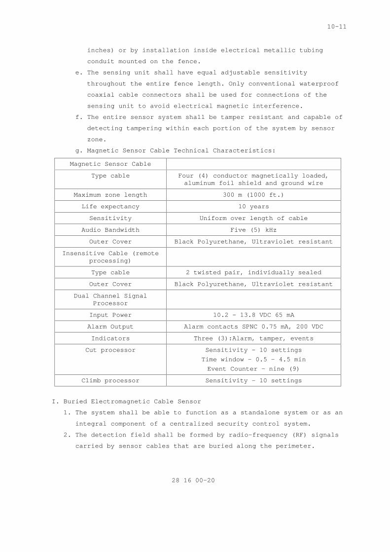
f. The entire sensor system shall be tamper resistant and capable of
detecting tampering within each portion of the system by sensor
zone.
g. Magnetic Sensor Cable Technical Characteristics:
Magnetic Sensor Cable
Type cable Four (4) conductor magnetically loaded, aluminum foil shield and ground wire
Maximum zone length 300 m (1000 ft.)
Life expectancy 10 years
Sensitivity Uniform over length of cable
Audio Bandwidth Five (5) kHz
Outer Cover Black Polyurethane, Ultraviolet resistant
Insensitive Cable (remote processing)
Type cable 2 twisted pair, individually sealed
Outer Cover Black Polyurethane, Ultraviolet resistant
Dual Channel Signal Processor
Input Power 10.2 – 13.8 VDC 65 mA
Alarm Output Alarm contacts SPNC 0.75 mA, 200 VDC
Indicators Three (3):Alarm, tamper, events
Cut processor Sensitivity - 10 settings Time window – 0.5 – 4.5 min Event Counter – nine (9)
Climb processor Sensitivity – 10 settings
I. Buried Electromagnetic Cable Sensor
1. The system shall be able to function as a standalone system or as an
integral component of a centralized security control system.
2. The detection field shall be formed by radio-frequency (RF) signals
carried by sensor cables that are buried along the perimeter.

10-11
28 16 00-21
3. The RF signals shall form an invisible electromagnetic detection
field around the sensor cables that can detect the presence of an
intruder passing through the field.
4. The system shall detect moving intruders that have a significant
electromagnetic field (e.g. humans, vehicles, and other large
conductive objects) while rejecting other environmental stimuli such
as birds, small animals, weather elements.
5. A sensor module shall contain the electronics required to:
a. Transmit and receive the RF signal without the use of an external
antenna.
b. Monitor the detection fields of two (2) zones and produce an
alarm when an intruder enters the zones.
6. Field power modules shall be available for standalone systems and
networked systems.
7. As a standalone system, the primary operator interface shall be a
local interface module that is connected directly to the sensor
module.
8. As part of a network configuration, the primary operator interface
shall be a personal computer (PC) based central controller. The
central controller shall monitor the performance of the entire
buried coaxial cable outdoor intrusion detection system and any
auxiliary sensors. The central controller shall have the capability
of acknowledging, processing and reporting alarms. A customized
color site map that is displayed on the PC monitor shall be an
available option for the system to monitor sensor locations.
9. Transmission and reception shall be accomplished without the use of
antennae. The RF signal shall be monitored and analyzed by the
sensor module for any changes in the detection field properties that
would indicate the presence of an intruder.
10. Alarms generated by internal electronic processes (cables excluded)
shall not exceed one (1) per zone per month. System generated alarms
are averaged based on the total number of zones in the system.
11. When the system is calibrated in accordance with the manufacturers'
recommendations, the detection field shall be continuous and uniform
over the protected site perimeter.
12. When system sensitivity is calibrated according to manufacturers'
recommendations, the detection field shall not detect a valid target
that is a minimum of 2 m. (6.5 ft) from the nearest sensor cable.

10-11
28 16 00-22
13. Buried Electromagnetic Cable Sensor Technical Characteristics:
Burial Medium Clay, sand, soil, asphalt, concrete
Snow limitation Up to 30c. (1 foot) deep
Degradation Guaranty Minimum 10 yr.
Detection Medium Radio Frequency (RF)
Detection Coverage Maximum 200m (656 ft.) per zone
Detection Capability Human: >34 kg. (75 lbs)
Detection Speed Human walk, crawl, run, roll, jump 2.5 cm/sec (1 in./sec.) –15 m/sec
(50 ft./sec.) regardless of direction across field
Velocity Response Programmable
Detection Probability Human: 99% with 95% confidence factor Animal: Less than 10 kg. (22 lbs.) Less than 5% with 90% confidence
factor
Terrain Detection Capabilities
Even to uneven ground with maximum (max) grade 4 m (13 ft.)
Corner bend radius 6.5m (22 ft.)
Detection Field Cross Section
Upright walking; Height1m: (3.2 ft.) above ground Width: 2m (6.5 ft.) single cable 3m. (9.75 ft) double cable
Sensing Element Ported (leaky) coaxial cables
Cable Construction Abrasion and chemical resistant, high density polyethylene, with flooding
compound
Cable Requirements Two (2):Transmit cable, receive cable
Configurations Available
Two (2):Single cable, double cable
Cable Lengths 50 m (164 ft.), 100 m (328 ft.), 150 m (492 ft.), 200 m (656 ft.)
Zone Length Minimum 10 m (33 ft.)
Antenna Requirements None
False alarm rate Less than one (1) per day
14. Sensor Module: Each sensor module shall transmit, receive and
process the electromagnetic detection fields independently from
other sensor modules. Failure of one (1) sensor module shall not
affect the remainder of the perimeter. The sensor module shall
10-11
28 16 00-23
operate as either a standalone unit, or in a network configuration
in conjunction with a central controller. The sensor module shall be
mounted in a weatherproof enclosure when installed outdoors as
follows.
a. The sensor module shall use an adaptive filter to analyze the
detection signal and adjust the signal processing to reduce
nuisance alarms caused by environmental factors such as rainfall
or slow-running water.
b. The sensor module shall identify, by type, sensor, tamper, and
failure alarms either locally at the sensor module, or centrally
at a central controller. The sensor cables shall provide the data
paths between the sensor modules, for the transmission, reception
and display of alarm conditions.
c. Each sensor module shall include an internal interface for the
collection of auxiliary sensor data.
d. It shall be possible to supply power directly to each unit for
applications that require either a single sensor module or
multiple sensor modules with independent power sources.
e. The sensor module's response shall be demonstrated by an analog
output signal that can be displayed on a voltmeter or on an
analog voltage-recording device. The output signal shall be
encoded to indicate the alarm trip-point, thereby showing the
sensor module’s degree of detection above or below the level
required to cause an alarm.
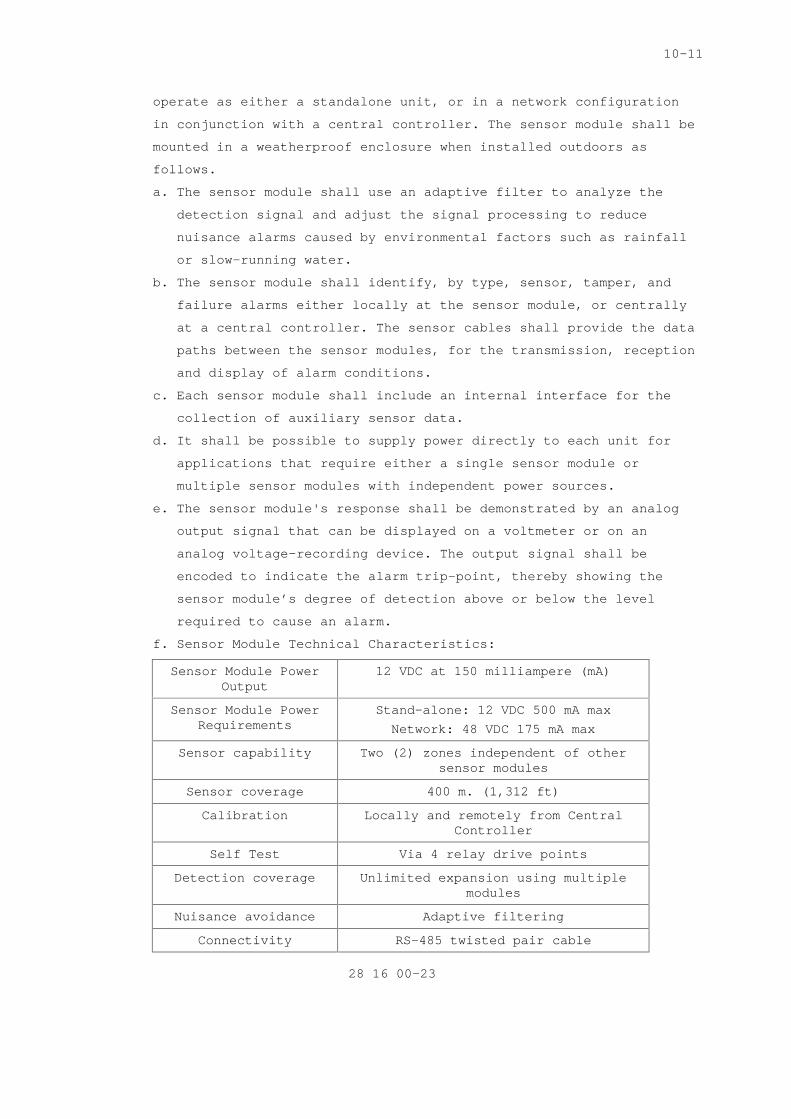
f. Sensor Module Technical Characteristics:
Sensor Module Power Output
12 VDC at 150 milliampere (mA)
Sensor Module Power Requirements
Stand-alone: 12 VDC 500 mA max Network: 48 VDC 175 mA max
Sensor capability Two (2) zones independent of other sensor modules
Sensor coverage 400 m. (1,312 ft)
Calibration Locally and remotely from Central Controller
Self Test Via 4 relay drive points
Detection coverage Unlimited expansion using multiple modules
Nuisance avoidance Adaptive filtering
Connectivity RS-485 twisted pair cable
10-11
28 16 00-24
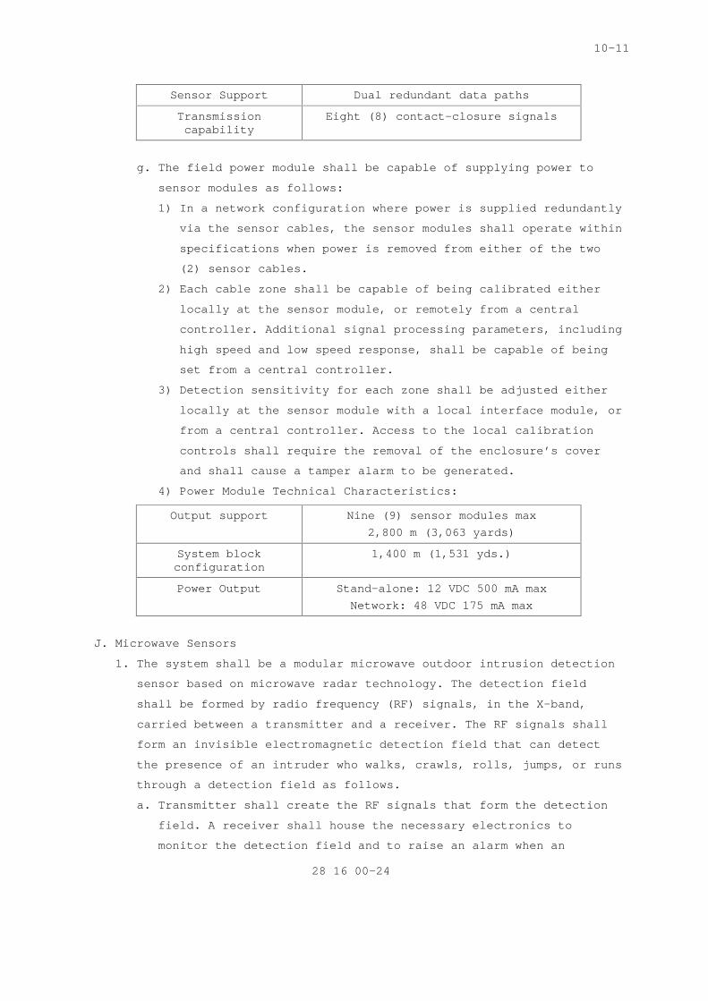
Sensor Support Dual redundant data paths
Transmission capability
Eight (8) contact-closure signals
g. The field power module shall be capable of supplying power to
sensor modules as follows:
1) In a network configuration where power is supplied redundantly
via the sensor cables, the sensor modules shall operate within
specifications when power is removed from either of the two
(2) sensor cables.
2) Each cable zone shall be capable of being calibrated either
locally at the sensor module, or remotely from a central
controller. Additional signal processing parameters, including
high speed and low speed response, shall be capable of being
set from a central controller.
3) Detection sensitivity for each zone shall be adjusted either
locally at the sensor module with a local interface module, or
from a central controller. Access to the local calibration
controls shall require the removal of the enclosure’s cover
and shall cause a tamper alarm to be generated.
4) Power Module Technical Characteristics:
Output support Nine (9) sensor modules max 2,800 m (3,063 yards)
System block configuration
1,400 m (1,531 yds.)
Power Output Stand-alone: 12 VDC 500 mA max Network: 48 VDC 175 mA max
J. Microwave Sensors
1. The system shall be a modular microwave outdoor intrusion detection
sensor based on microwave radar technology. The detection field
shall be formed by radio frequency (RF) signals, in the X-band,
carried between a transmitter and a receiver. The RF signals shall
form an invisible electromagnetic detection field that can detect
the presence of an intruder who walks, crawls, rolls, jumps, or runs
through a detection field as follows.
a. Transmitter shall create the RF signals that form the detection
field. A receiver shall house the necessary electronics to
monitor the detection field and to raise an alarm when an

10-11
28 16 00-25
intruder enters the field. The transmitter and receiver shall be
powered individually, as a standalone unit.
b. An electromagnetic wave is emitted by the antenna of the
transmitter and received by the antenna of the receiver. The
receiver shall detect changes that are caused by the presence of
an intruder.
c. The system shall detect moving intruders having a significant
electromagnetic cross-section (e.g. humans, vehicles, and other
large conductive objects) rejecting other environmental stimuli.
d. The system shall be capable of detecting human intruders moving
through the detection field regardless of the direction of
motion.
e. Processor description: The receiver shall contain the necessary
electronics to perform the signal processing for the detection
zone. The transmitter and receiver shall be operated as a
standalone unit with independent power and data. Both the
transmitter and receiver shall be installed in weatherproof
enclosures.
f. Distributed processing: Transmitter-receiver pairs distributed
along a perimeter shall provide extended range and fail-safe
operation. The failure of one (1) pair shall not affect the
coverage of the remainder of the perimeter.
g. Alarms: The signal processor shall identify intrusion and
tamper/fail alarms locally, at the transmitter or receiver.
1) An alarm caused by opening the outer enclosure of the
transmitter or receiver shall be identified as a tamper alarm.
Tamper alarms shall be distinctive from intrusion alarms.
2) Alarms caused by power failure or internal electronic failure
are fail alarms, distinctive from intrusion alarms.
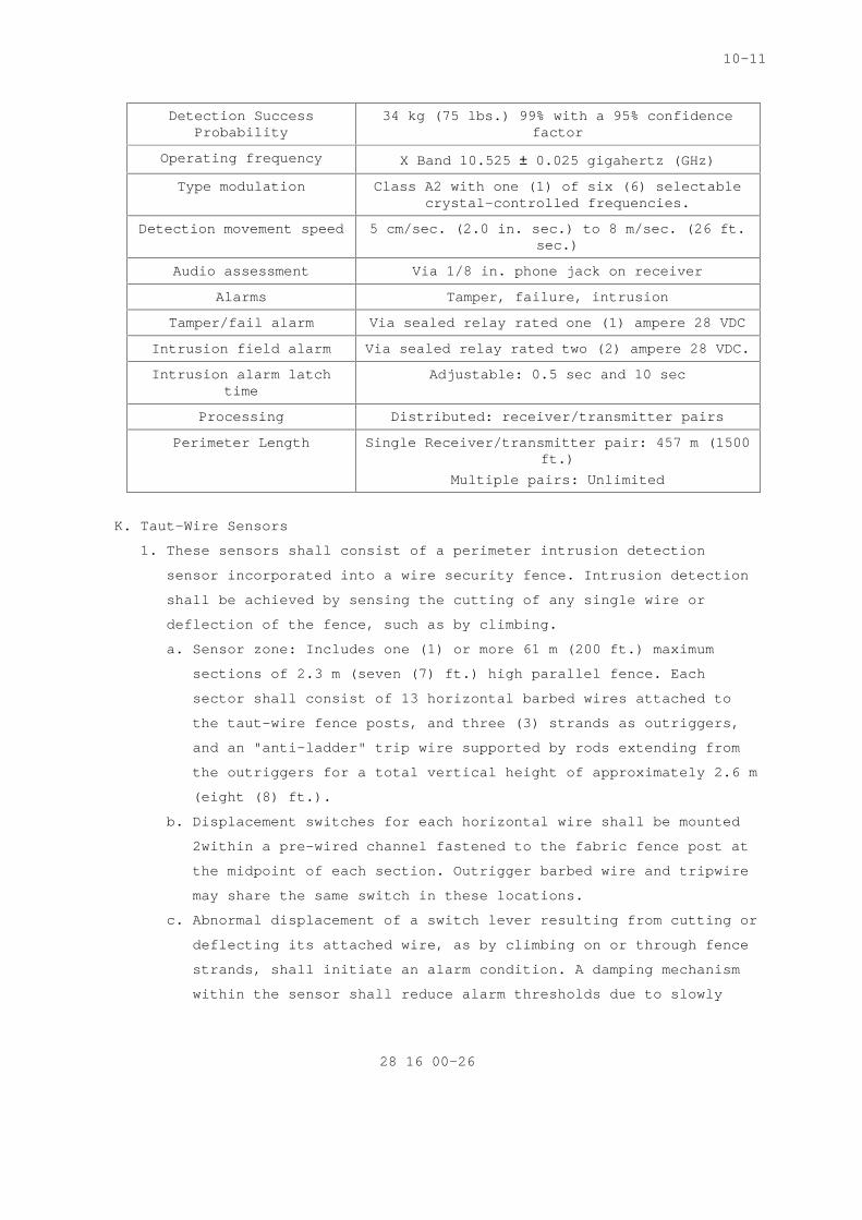
h. Microwave Sensor System Technical Characteristics:
Operating voltage Transmitter
11 – 15 VDC 70mA max. current
Operating voltage Receiver
11 – 15 VDC 30mA max. current
Operating Environment –30ºC (-22F) and 60ºC (140 F)
LEDs POWER ON, WRONG CHANNEL, ALARM
Maximum zone length 10 m (33 ft.) and a maximum of 457 m (1500 ft.) per zone.
10-11
28 16 00-26
Detection Success Probability
34 kg (75 lbs.) 99% with a 95% confidence factor
Operating frequency X Band 10.525 ± 0.025 gigahertz (GHz)
Type modulation Class A2 with one (1) of six (6) selectable crystal-controlled frequencies.
Detection movement speed 5 cm/sec. (2.0 in. sec.) to 8 m/sec. (26 ft. sec.)
Audio assessment Via 1/8 in. phone jack on receiver
Alarms Tamper, failure, intrusion
Tamper/fail alarm Via sealed relay rated one (1) ampere 28 VDC
Intrusion field alarm Via sealed relay rated two (2) ampere 28 VDC.
Intrusion alarm latch time
Adjustable: 0.5 sec and 10 sec
Processing Distributed: receiver/transmitter pairs
Perimeter Length Single Receiver/transmitter pair: 457 m (1500 ft.)
Multiple pairs: Unlimited
K. Taut-Wire Sensors
1. These sensors shall consist of a perimeter intrusion detection
sensor incorporated into a wire security fence. Intrusion detection
shall be achieved by sensing the cutting of any single wire or
deflection of the fence, such as by climbing.
a. Sensor zone: Includes one (1) or more 61 m (200 ft.) maximum
sections of 2.3 m (seven (7) ft.) high parallel fence. Each
sector shall consist of 13 horizontal barbed wires attached to
the taut-wire fence posts, and three (3) strands as outriggers,
and an "anti-ladder" trip wire supported by rods extending from
the outriggers for a total vertical height of approximately 2.6 m
(eight (8) ft.).
b. Displacement switches for each horizontal wire shall be mounted
2within a pre-wired channel fastened to the fabric fence post at
the midpoint of each section. Outrigger barbed wire and tripwire
may share the same switch in these locations.
c. Abnormal displacement of a switch lever resulting from cutting or
deflecting its attached wire, as by climbing on or through fence
strands, shall initiate an alarm condition. A damping mechanism
within the sensor shall reduce alarm thresholds due to slowly

10-11
28 16 00-27
changing environmental phenomena such as the ground shifting,
daily and seasonal temperature variations, winds changes, etc.
d. Sensor switches shall be provided with electrical contact
closures as a means for initiating an alarm condition.
e. The system shall provide relay outputs to interface alarm outputs
with the overall IDS.
f. Taut-wire Sensor Technical Characteristics:
Power requirements Input: 120 – 208 VAC
Sensor zone control unit capability
Up to 10 zones
Sensitivity 19 mm (0.75 in.)
Environment Limits Winds up to 56 km/h (35 mph)
L. Electrostatic Field Sensors
1. These sensors generate an electrostatic field around one (1) or more
horizontal wires and detect intrusion of the electrostatic field as
follows.
a. Sensors shall initiate an alarm when an intruder attempts to
approach or scale a fence or physical barrier. Electrostatic
field sensors shall detect human presence by generating an
electric field around one (1) or more horizontal wires that
detects the induced signal in parallel sensing wires.
b. Sensors shall monitor the induced signal for changes that result
from the presence of a human body, which distorts coupling
between transmitting and sensor wires.
c. Sensor components shall consist of one (1) or more signal
generator field wires and mounting hardware, sensing wires, an
amplifier/signal processors, power supplies, and necessary
circuitry hardware. Mounting and support hardware shall be
provided by the equipment manufacturer.
d. Wires shall be spring tension-mounted and provided with end-of-
line terminators to detect cutting, shorting, or breaking of the
wires.
e. Sensor configuration shall be able to detect an intruder that may
crawl under the bottom wire, through the wires, or over the top
wire by divided sensor zones.
f. Signal processing circuitry shall provide filtering to
distinguish nuisance alarms.

10-11
28 16 00-28
g. Sensor configuration shall incorporate balanced, opposed field
construction to eliminate distant field noise.
h. Sensor sensitivity shall be adjustable. Adjustment controls shall
be inaccessible to operating personnel and system sensitivity
controls shall be set at approximately midrange.
i. Sensors shall provide some means of indicating an alarm condition
at the protected perimeter to facilitate installation and
calibration.
j. The sensor system shall include an indicator disabling device
within a tamperproof enclosure.
2. Electrostatic Field Sensor Technical Characteristics:
Power 115 -120 VAC transformer
Operating Power Requirements
16-22 VAC, 225 mA single zone 275 dual zone
Detection Sensitivity 77 lbs within 915 mm (3 ft.)- midrange setting
Detection Velocity 30 m (0.1 ft.) - 300 m (10 ft.) per sec
Supervision AC Monitoring of fence and field wires – open, short, and grounded
circuits
Tamper Switch One (1)-pole, two (2) position
Lightening arrestor Transistors on all relay output and power inputs
Battery Charger Built-in
Processor Enclosure Base plate, steel NEMA enclosure Weather resistant
M. Gate Sensors
1. They shall be provided in accordance with specific fence sensor
manufacturer's recommendations to ensure continuous fence sensor
zone protection for the entire protected perimeter.
a. When gate units are not provided by the fence sensor
manufacturer, provide separately zoned Balanced Magnetic Switch
(BMS) gate sensors.
b. Sensors shall perform as specified in Section 2.3-E.6 entitled
"Balanced Magnetic Switches (BMS)."

10-11
28 16 00-29
2.11 INTERIOR DETECTION DEVICES (SENSORS)
A. The IDS shall consist of interior, exterior, and other detection
devices that are capable of:
1. Locating intrusions at individually protected asset areas or at an
individual portal;
2. Locating intrusions within a specific area of coverage;
3. Locating failures or tampering of individual sensors or components.
B. Provide and adjust for devices so that coverage is maximized in the
space or area it is installed in. For large rooms where multiple
devices are required, ensure device coverage is overlapping.
C. Detection sensitivity shall be set up to ensure maximum coverage of the
secure area is obtained while at the same time limiting excessive false
alarms due to the environment and impact of small animals. All
detection devices shall be anti-masking with exception of video motion
detection.
D. Dual sensor technology shall be used when possible. Sensor technology
shall not be of the same type that is easily defeated by a single
method. This will reduce the amount of false alarms.
E. Interior Environmental Conditions: Systems shall be able to operate in
environmentally protected interior areas and shall meet operational
performance requirements for the following ambient conditions:
1. If components are installed in unheated areas they shall be able to
operate in temperatures as low as -17 C (0 F);
2. Interior Sensor Environmental Characteristics:
Temperatures 0 to 50 C (32F to 120 F)
Pressure Sea Level to 4573m (15,000 ft.) above sea level
Humidity 5% - 95%
Fungus Components of non-fungus nutrient materials
Acoustical Noise Suitable for high noise environments above 100db
F. Balanced Magnetic Switches (BMS)
1. BMS switches shall be surface or recessed mounted according to
manufacturer’s instructions. Recessed mounted is the preferred
method to reduce tampering or defeating of the system. Switches
shall activate when a disturbance in the balanced magnetic field
occurs.

10-11
28 16 00-30
2. Switches shall have a minimum of two (2) encapsulated reed switches.
3. Contractor shall provide each BMS with a current protective device,
rated to limit current to 80% of the switch capacity.
4. Surface Mounted BMS: For exterior application, components shall be
housed in weatherproof enclosures.
5. BMS field adjustments in the fixed space between magnet and switch
housing shall not be possible. Attempts to adjust or disturb the
magnetic field shall cause a tamper alarm.
6. BMS Technical Characteristics:
Maximum current .25 amperes
Maximum voltage 30 VDC
Maximum power 3.0 W (without internal terminating resistors). 1.0 W (with internal
terminating resistors).
Components Three (3) pre-adjusted reed switches Three (3) pre-adjusted magnets
Output contacts Transfer type SPDT
Contact rating 0.5 amperes, 28 VDC
Switch mechanism Internally adjustable ¼ - ½ in. (6-13 mm)
Wiring Two (2) wires #22 American Wire Gauge (AWG), three (3) or 11 foot attached
cable
Activation lifetime 1,000,000 activations
Enclosure Nonferrous materials
Tamper alarm activation
Cover opened 3 mm (1/8 in.) and inaccessible until actuated
G. Window Intrusion Detection
1. These IDS devices shall detect intrusions thru inertia (shock) or by
sound, and shall utilize either a Breakwire Sensor or Acoustic and
Seismic Sensor.
2. Break wire Sensors (wire trap):
a. Detect intrusion thru shock or breakage of window glazing. Also
used for the protection of utility openings.
b. Sensors shall consist of fine wire embedded in or affixed to
interior of glazing. Breakage of protected glazing shall result
in wire breakage.
c. Wire shall be hard-drawn copper up to #26 AWG diameter.

10-11
28 16 00-31
d. If sensors are affixed to glazing the sensor shall be protected
by a clear coating which shall not affect sensor functioning.
e. Sensor shall be terminated in insulated connectors which are
concealed and tamper resistant.
f. Protection of inlet openings:
1) Shall consist of up to 26 AWG hard-drawn copper wire with a
tensile strength of 17.8 N 4 pounds maximum.
2) Wire shall be interlaced throughout the opening such that no
opening between wires shall be larger than 100 mm (4 in.. on
center.
3) Sensors shall be terminated so that attempts to cut the wire
or otherwise enlarge openings between wires shall cause an
alarm.
4) Sensors shall be terminated in insulated connectors which are
concealed and tamper resistant.
H. Acoustic and Seismic Glass Break Detectors
1. Detects intrusion thru the use of audible sound and vibration
emitted from the breaking of glass using a tuned frequency range and
sound pattern recognition. This initiates an alarm when glass they
protect is broken or cracked.
2. Detectors shall be installed in strict conformance with
manufacture’s installation instructions.
3. The detector’s power circuit shall be switched via an output relay
on the control panel to provide latching alarm LED reset capability.
4. Sensors shall be contained in a fire-resistant ABS plastic housing
and must be mounted in contact with a window.
5. Sensing shall be accomplished through the use of a mechanical
filtered piezoelectric element.
6. Sensors shall have a sensitivity adjustment controlling output
voltage from the piezoelectric element which triggers a solid-state
latching device.
7. Sensors shall selectively filter input to minimize false alarms and
not initiate alarm in response to ambient seismic vibrations or
other ambient stimuli.
8. A manufacture’s test unit will be used to validate the sensor by
simulating glass breakage.

10-11
28 16 00-32
9. The Contractor shall provide sensors for adjusting sensitivity and
two-sided polyurethane tape with acrylic adhesive for window
attachment.
10. Sensor shall include exterior label to protect adhesive tape from
direct sunlight.
11. Window Intrusion Detection Sensor Technical Specifications:
Power Auxiliary power supply 12 VDC @ 25 mA (+/-) 10%
Power Input 10 – 15 VDC at 16mA protected against reverse polarity, 20 mA during relay
closure
Relay Output Rating Minimum of 25 VDC mA
Coverage Audio 6,000 Square ft.
Coverage Glass Break 7.5 m (25 ft.) wide by 7.5 m wide (25 ft.)
Minimum: 7.62 m (25 feet) from the detector to the furthest point on
protected glass.
Audio Output 300 – 12,000 HZ
Alarm Output Relay NO or NC selectable
Interconnection 12 pin Panduit connector, 22 AWG
Radio Frequency Interface
No alarm or setup on between frequencies 26 – 100 MHz 50 v/m
Immunity to mobile RF interference 100 watts 3 m @ (9.8 Ft.) in 27-100
MHz range
Alarm period Two (2) to three (3)
Mounting Ceiling, same wall, adjacent wall, opposite wall
Features Test and alarm LEDs for acoustic seismic and alarm condition latching, Alarm LED and tamper switch on cover.
Alarm verification Digital signal processing or dual acoustic processing technologies
Detection ability Single and multi-pane glass, wired glass, tempered and laminated glass
to 6 mm (¼ inch) or thickness
I. Screening
1. This material shall be used on windows to protect and detect
intrusion as follows.

10-11
28 16 00-33
a. Security screens shall be constructed from a maximum of 26 AWG
insulated hard-drawn copper.
b. Screens shall be connected to an alarm circuitry by means of
flexible armored cords. Security screen circuitry shall provide
end-of-line resistors in series or equivalent methods ensuring
alarm activation if short-circuiting of the screen is attempted.
c. If unable to install a break wire sensor (wire traps), then
tamper switches will be provided.
d. Contractor shall provide tamper switches in the frames as
required with not less than one (1) switch on each side if
dimensions are 610 mm two ((2) ft. square) or less, and two (2)
switches if dimensions exceed 610 mm (2 ft. square). Tamper
switches shall be corrosion-resistant, spring-operated, and shall
initiate an alarm with a movement of 50 mm (two (2) in.) or less
before access to the switch is possible.
e. Electrical characteristics of the switch shall match the alarm
system requirements.
J. Vibration Sensors
1. These sensors shall initiate alarms upon detecting drilling,
cutting, or blasting through walls, or other methods of forced entry
through a structure as follows.
2. Sensors shall detect and selectively amplify signals generated by
forced penetration of a protective structure.
3. Sensors shall be designed to give peak response to structurally
conveyed vibrations associated with forcible attack on the protected
surface.
4. Sensors will initiate an alarm if attempts are made to remove them
from the surface of the wall.
5. Sensors shall be enclosed in protective mountings.
6. Sensors shall include an adjustable alarm discriminator to prevent
incidental vibrations which may occur from triggering the alarm
circuit.
7. Sensors shall be provided with a tamper switch.
8. Sensor sensitivity shall be individually adjustable unless a sensor
is designed to accommodate vibration ranges of specific surface type
on which it will be mounted. Sensitivity adjustments shall not be
accessible without removing the sensor cover. Also, a sensor shall
not be responsive to airborne sound.

10-11
28 16 00-34
9. Vibration Sensor Technical Characteristics:
Power requirements External DC power source Eight (8)- 14.5 VDC, two (2) volt max
peak to peak ripple
Alarm output Form C (NO/C/NC) solid state alarm relay, rated 100 mA, 28 VDC
Tamper Connection Tamper switch and external magnetic
Current rating and alarm output
No alarm state 20mA SPDT relay contact rating (Form C)
Sensor range Concrete (poured) 4 m (13.2 ft.) Concrete block 2 m (6.6 ft.) Brick block 1 m (3.3 ft.)
Frequency range 3kHz-20kHz (-15db) 7kHz-10kHz (-10db)
Adjustable Sensitivity eight (8) steps Alarm response 0-30 sec
K. Passive Infrared Motion Sensors (PIR)
1. These sensors shall detect an intruder presence by monitoring the
level of infrared energy emitted by objects within a protected zone
and meet ANSI PIR-01 Passive Infrared Motion Detector Standards
Features for Enhancing False Alarm Immunity. An alarm shall be
initiated when motion and temperature changes within set patterns
are detected as follows.
2. The detector shall provide multiple detection zones distributed at a
variety of angles and distance.
3. Sensors shall be passive in nature; no transmitted energy shall be
required for detection.
4. Sensors shall be sensitive to infrared energy emitted at wavelengths
corresponding to human body and other objects at ambient
temperatures.
5. Sensors shall not alarm in response to general area thermal
variations and shall be immune to radio frequency interference.
6. Sensors shall not be susceptible to changes in temperature due to an
air conditioner being turned on or off.
7. Sensors shall be housed in a tamper-alarmed enclosure.
8. Sensor detectors shall include motion analyzer processing,
adjustable lens, and walk test LED’s visible from any angle.
10-11
28 16 00-35
9. Sensors shall provide some means of indicating an alarm condition
during installation and calibration. A means of disabling the
indication shall be provided within the sensor enclosure.
10. Sensor detectors shall include a motion monitoring verification
circuit that will signal trouble or alarm if the detector fails to
detect motion for an extended period.
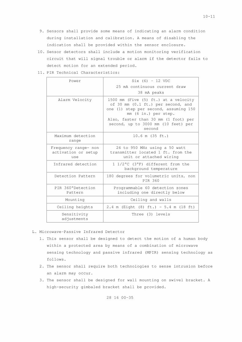
11. PIR Technical Characteristics:
Power Six (6) – 12 VDC 25 mA continuous current draw
38 mA peaks
Alarm Velocity 1500 mm (Five (5) ft.) at a velocity of 30 mm (0.1 ft.) per second, and
one (1) step per second, assuming 150 mm (6 in.) per step.
Also, faster than 30 mm (1 foot) per second, up to 3000 mm (10 feet) per
second
Maximum detection range
10.6 m (35 ft.)
Frequency range- non activation or setup
use
26 to 950 MHz using a 50 watt transmitter located 1 ft. from the
unit or attached wiring
Infrared detection 1 1/2°C (3°F) different from the background temperature
Detection Pattern 180 degrees for volumetric units, non PIR 360
PIR 360°Detection Pattern
Programmable 60 detection zones including one directly below
Mounting Ceiling and walls
Ceiling heights 2.4 m (Eight (8) ft.) – 5.4 m (18 ft)
Sensitivity adjustments
Three (3) levels
L. Microwave-Passive Infrared Detector
1. This sensor shall be designed to detect the motion of a human body
within a protected area by means of a combination of microwave
sensing technology and passive infrared (MPIR) sensing technology as
follows.
2. The sensor shall require both technologies to sense intrusion before
an alarm may occur.
3. The sensor shall be designed for wall mounting on swivel bracket. A
high-security gimbaled bracket shall be provided.

10-11
28 16 00-36
4. The PIR fields of view shall be focused on the pyroelectric element
by means of an internal multi-faceted mirror.
5. The sensor shall incorporate a look-down lens system that detects
the passing of an intruder directly beneath the sensor.
6. The sensor shall incorporate a microwave supervision system which
shall activate the trouble output if the device technology fails.
7. The sensor shall incorporate self-diagnostics which shall monitor
the sensor systems and report a trouble to the control panel if any
system device fails.
8. The sensor shall have compensation against loss of sensitivity as
the ambient temperature nears human body temperature.
9. MPIR Technical Characteristics:
Technology Microwave and Passive Infrared
Power Nine (9) – 15 VDC max current consumption 22 mA at 12 VDC
Operating Temperature 0° C (32°F) – 49° C (120° F)
Detection Area 30 m (98 ft.) long by 3 m (9.8 ft.) wide or 21 m (69 ft.) long by 21m
(69 ft.) wide
Electronics Microcontroller based
Alarm Contact Form-C rated 125 mA, 28 VDC
Tamper Contact 125 mA, 28 VDC
Trouble Contact Form-B rated 25 mA, 30 VDC
Microwave Operating Frequency
10.525 GHz
Microwave Sensitivity Adjustable on circuit board
Detection pattern adjustment
Changing of internal lens
Sensing element Pyro-electric
LED Indicators PIR, microwave, alarm
Bug and Dust protection
zero-clearance, gasket bug guard
Lens Interchangeable: standard 18x24 m (60x80 ft.), corner mounting, ultra-wide, pet alley, long range, room and
corridor combo, room and ceiling combo, creep zone
M. Photoelectric Sensors

10-11
28 16 00-37
1. The sensor devices shall be able to detect an intruder presence by
sending out a series of infrared or ultraviolet beams. Intrusion is
based on disruption of the signal beams as follows.
a. Sensors shall consist of a modulating transmitter, focusing
lenses, mirrors, demodulating receiver, power supply, and
interconnecting lines.
b. Beam transmitters shall be designed to emit light. Beams may be
reflected by one (1) or more mirrors before being received and
amplified.
c. The photoelectric sensor shall initiate an alarm when the beam is
interrupted with monitoring controls set at midrange.
d. Transmitted beams shall be uniquely modulated to prohibit defeat
of the IDS system by shining another light source into the
receiver.
e. Sensors shall provide a means of local alarm indication on the
detector for use at the protected zone during installation and
calibration.
f. Sensors shall include an indicator-disabling device within the
sensor enclosure.
g. Sensors shall utilize automatic gain control or be provided with
sensitivity adjustments to allow for various beam lengths.
h. Sensor controls shall be inaccessible to operating personnel.
i. Sensors that use multiple beams shall be tested by attempting to
crawl under and jump through and over beams. Each system sensor
shall provide cutoffs of at least 90% to handle a high percentage
of light cutoffs prior to initiating an alarm.
j. Sensor components shall be housed in tamper-alarmed enclosure.
2. Photoelectric Sensor Technical Characteristics:
Power requirements Nine (9)-16 VDC, protected against reverse polarity
Relay output Normally closed. 18 ohm resister in series with contacts. 0.5 amperes
resistance/24 VDC
Current Transmitter 15 mA, Receiver 15 mA
LED Alignment, walk-test alarm, off
Range Indoor: 39 m (130 ft.) Outdoor19.5 m: (65 ft.)
Alarm relay contacts Two (2) amperes at 120 VAC minimum

10-11
28 16 00-38
Enclosure High impact acrylic
Type Dual beam
Mounting Wall, corner, flush
Beam width Six (6) degrees
Receiver field of view
Six (6) degrees horizontal and vertical
Adjustments Vertical +10 – 20 degrees Horizontal 30 degrees
Alarm period Two (2) – three (3) sec
Infrared source Long-life Gallium Arsenide LED
Infrared sensor PIN photodiode
Transmitter Frequency One (1) kHz 10 microsecond pulse width
IR Wavelength 950 nm
N. CCTV Video Motion Detection Sensors: Refer to Section 28 23 00 VIDEO
SURVEILLANCE that outlines related video motion detection requirements.
2.12 TAMPER ALARM SWITCHES
A. The following IDS sensors shall be used to monitor and detect potential
tampering of sensors, control panels and enclosures.
1. Tamper Switches: All enclosures including cabinets, housings, boxes,
raceways, and fittings with hinged doors or removable covers
containing circuits and power supplies related to the IDS shall
include corrosion-resistant tamper switches.
2. Tamper alarms shall be annunciated to be clearly distinguishable
from IDS alarms.
3. Tamper switches will not be in a viewable from a direct line of
sight perspective. The minimum amount of time the tamper switch
becomes active and sends a signal after an enclosure is opened or
panel removable is attempted, shall be one (1) second.
4. Tamper switches will initiate when enclosure doors or covers is
removed as little as 6.35 mm (1/4 inch) from the closed position
unless otherwise indicated. Tamper switches shall be:
a. Push/pull automatic reset type;
b. Inaccessible until switch is activated;
c. Spring-loaded and held in closed position by door or cover; and
10-11
28 16 00-39
d. Wired to break a circuit when door or cover is removed with each
sensor annunciated individually at a central reporting processor.
5. Fail-Safe Mode: Shall provide the capability to detect and
annunciate diminished functional capabilities and perform self-
tests. Fail-safe alarms shall be annunciated to be clearly
distinguishable from other types of alarms.
2.13 POWER SUPPLY
A. A power supply shall only be utilized if the control panel is unable to
support the load requirements of the IDS system.
B. All power supplies shall be UL rated and able to adequately power two
entry control devices on a continuous base without failure.
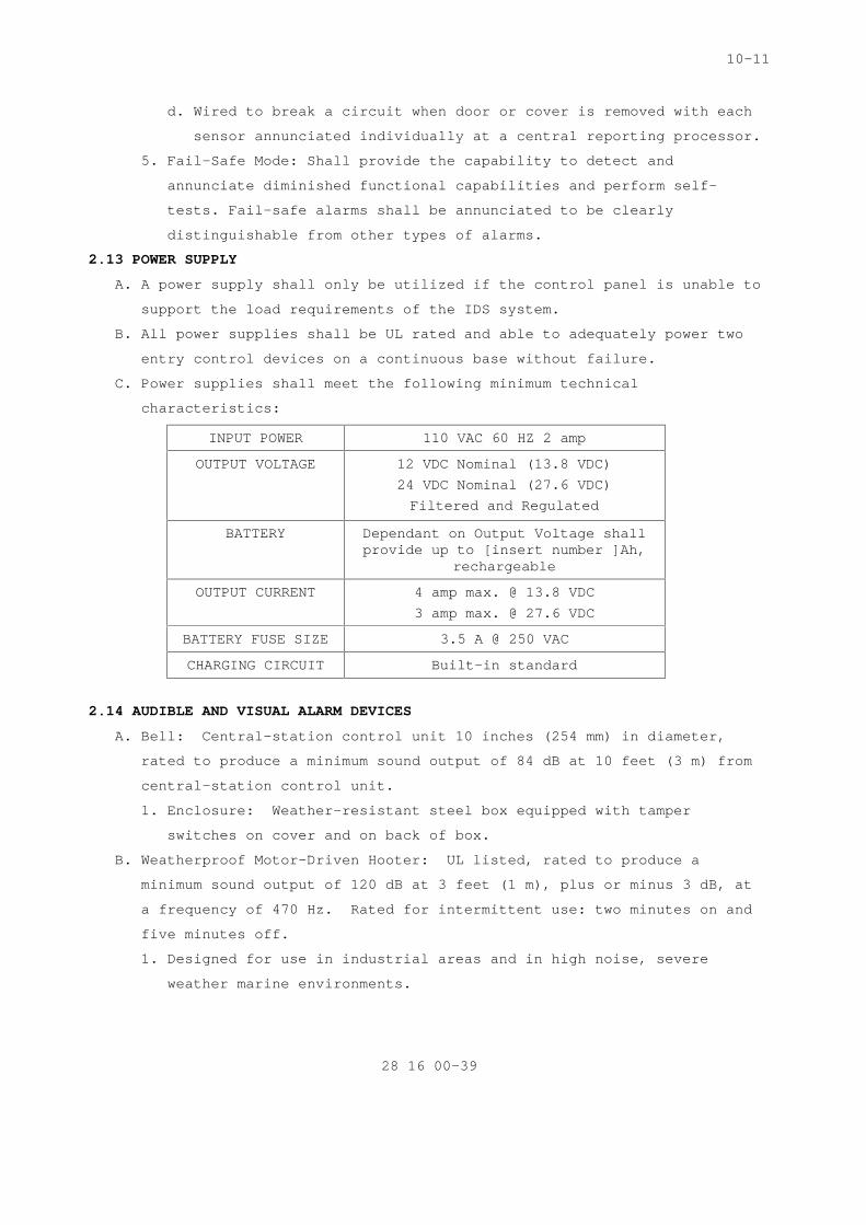
C. Power supplies shall meet the following minimum technical
characteristics:
INPUT POWER 110 VAC 60 HZ 2 amp
OUTPUT VOLTAGE 12 VDC Nominal (13.8 VDC) 24 VDC Nominal (27.6 VDC) Filtered and Regulated
BATTERY Dependant on Output Voltage shall provide up to [insert number ]Ah,
rechargeable
OUTPUT CURRENT 4 amp max. @ 13.8 VDC 3 amp max. @ 27.6 VDC
BATTERY FUSE SIZE 3.5 A @ 250 VAC
CHARGING CIRCUIT Built-in standard
2.14 AUDIBLE AND VISUAL ALARM DEVICES
A. Bell: Central-station control unit 10 inches (254 mm) in diameter,
rated to produce a minimum sound output of 84 dB at 10 feet (3 m) from
central-station control unit.
1. Enclosure: Weather-resistant steel box equipped with tamper
switches on cover and on back of box.
B. Weatherproof Motor-Driven Hooter: UL listed, rated to produce a
minimum sound output of 120 dB at 3 feet (1 m), plus or minus 3 dB, at
a frequency of 470 Hz. Rated for intermittent use: two minutes on and
five minutes off.
1. Designed for use in industrial areas and in high noise, severe
weather marine environments.

10-11
28 16 00-40
C. Siren: 30-W speaker with siren driver, rated to produce a minimum
sound output of 103 dB at 10 feet (3 m) from central-station control
unit.
1. Enclosure: Weather-resistant steel box with tamper switches on
cover and on back of box.
D. Strobe: Xenon light complying with UL 1638, with a clear polycarbonate
lens.
1. Light Output: 115 cd, minimum.
2. Flash Rate: 60 per minute.
2.15 SECURITY FASTENERS
A. Security fasteners shall be operable only by tools produced for use on
specific type of fastener by fastener manufacturer or other licensed
fabricator. Drive system type, head style, material, and protective
coating as required for assembly, installation, and strength.
SPEC WRITER NOTE: Insert additional types of security fasteners below with other drive systems and head styles if necessary or for special applications. Coordinate type of security fasteners retained in this Section with other Sections specifying security fasteners. See Evaluations.
B. Drive System Types: Pinned Torx or pinned hex (Allen).
C. Socket Flat Countersunk Head Fasteners:
1. Heat-treated alloy steel, ASTM F 835 (ASTM F 835M).
2. Stainless steel, ASTM F 879 (ASTM F 879M), Group 1 CW.
D. Socket Button Head Fasteners:
1. Heat-treated alloy steel, ASTM F 835 (ASTM F 835M).
2. Stainless steel, ASTM F 879 (ASTM F 879M), Group 1 CW.
E. Socket Head Cap Fasteners:
1. Heat-treated alloy steel, ASTM A 574 (ASTM A 574M).
2. Stainless steel, ASTM F 837 (ASTM F 837M), Group 1 CW.
F. Protective Coatings for Heat-Treated Alloy Steel:
1. Zinc chromate, ASTM F 1135, Grade 3 or 4; for exterior applications
and interior applications where indicated.
2. Zinc phosphate with oil, ASTM F 1137, Grade I, or black oxide.
PART 3 - EXECUTION
SPEC WRITER NOTE: Delete and/or amend this all paragraphs and sub-paragraphs to

10-11
28 16 00-41
apply to only the equipment and devices that are being installed.
3.1 INSTALLATION
A. IDS installation shall be in accordance with Underwriters Laboratories
(UL) 639 Standards for Intrusion Detection Units and UL 634 Standards
for Connectors with Burglar Alarm Systems, and appropriate
manufacture’s installation manuals for each type of IDS.
B. Components shall be configured with appropriate “service points” to
pinpoint system trouble in less than 30 minutes.
C. The Contractor shall install all system components including VA
furnished equipment, and appurtenances in accordance with the
manufacturer's instructions and shall furnish all necessary connectors,
terminators, interconnections, services, and adjustments required for a
complete and operable system.
D. The IDS will be designed, engineered, installed, and tested to ensure
all components are fully compatible as a system and can be integrated
with all associated security subsystems, whether the system is a stand
alone or designed as a computer network.
E. The IDS shall be able to be integrated with other security subsystems.
Integration with these security subsystems shall be achieved by
computer programming and the direct hardwiring of the systems.
Determination for methodology shall be outlined when the system(s)
is/are being designed and engineered. For installation purposes, the
IDS shall utilize an output module for integration with other security
subsystems. The Contractor will ensure all connections are per the OEM
and that any and all software upgrades required to integrate the
systems are installed prior to system start-up.
F. For programming purposes, the Contractor shall refer to the
manufacturer’s requirements and Contracting Officer instructions for
correct system operations. This includes ensuring computers being
utilized for system integration meet or exceeds the minimum system
requirements outlined in the IDS software packages.
G. Lightening and power surges to the central alarm reporting and display
unit shall be protected at both ends against excessive voltages. This
requirement shall apply for circuits that are routed both in
underground conduits and overhead runs.
H. At a minimum, the Contractor shall install primary detection devices,
such as three electrode gas-type surge arresters, and secondary

10-11
28 16 00-42
protectors to reduce dangerous voltages to levels that will cause no
damage. Fuses shall not be permitted as protection devices.
I. The Contractor shall provide fail-safe gas tube type surge arresters on
exposed IDS data circuits. In addition, transient protection shall
protect against spikes up to 1000 volts peak voltage with a one-
microsecond rise time and 100-microsecond decay time, without causing
false alarms. The protective device shall be automatic and self-
restoring. Also, circuits shall be designed or selected assuming a
maximum of 25 ohms to ground.
J. Product Delivery, Storage and Handling:
1. Delivery: Deliver materials to the job site in OEM's original
unopened containers, clearly labeled with the OEM's name, equipment
model and serial identification numbers, and UL logo. The
Contracting Officer may inventory the IDS equipment at the time of
delivery and reject items that do not conform to this requirement.
2. Storage and Handling: Store and protect equipment in a manner that
will preclude damage as directed by the Contracting Officer.
K. Cleaning and Adjustments:
1. Cleaning: Subsequent to installation, clean each system component of
dust, dirt, grease, or oil incurred during installation in
accordance to manufacture instructions.
2. Prepare for system activation by following manufacturer’s
recommended procedures for adjustment, alignment, or
synchronization. Prepare each component in accordance with
appropriate provisions of the component’s installation, operations,
and maintenance instructions.
L. Tamper Switches
1. Install tamper switches to initiate an alarm signal when a panel,
box, or component housing door or cover is moved as little as 6.35
mm (1/4 inch) from the normally closed position unless otherwise
specified.
2. Locate tamper switches within enclosures, cabinets, housings, boxes,
raceways, and fittings to prevent direct line of sight to any
internal components and to prevent tampering with switch or
circuitry.
3. Conceal tamper switch mounting hardware so that the location of the
switch within the enclosure cannot be determined from the exterior.
M. Unique IDS Installation Components:

10-11
28 16 00-43
1. BMS Surface Mounted:
a. Surface mounted BMS housing for the switch element shall have the
capability to receive threaded conduit. Housing covers for
surface mounted BMS, if made of cast aluminum, shall be secured
by stainless steel screws. Magnet housing cover shall not be
readily removable and BMS housings shall be protected from
unauthorized access by a cover operated, corrosion-resistant
tamper device.
b. Conductors running from a door to alarm circuits shall be
contained within a flexible armored cord constructed from
corrosion-resistant metal. Each end of the armored cord shall
terminate in a junction box or other enclosure. Armored cord ends
shall be mechanically secured to the junction boxes by clamps or
bushings. Conductors within the armored cord shall be provided
with lug terminals at each end. Conductors and the armored cord
shall experience no mechanical strain as the door is removed from
fully open to closed position. Switch circuits shall initiate an
alarm if a short circuit is applied to the door cord.
c. For exterior application on double gates, both BMS elements must
be mounted on the gate. Flexible armored cord constructed from
corrosion-resistant metal shall be used to provide electrical
connection.
2. BMS Recessed Mounted:
a. Ball bearing door trips shall be mounted within vault door
headers such that when the locking mechanism is secured, the door
bolt engages an actuator, mechanically closing the switch.
b. Door bolt locking mechanisms shall be fully engaged before the
ball bearing door trip is activated. Also, circuit jumpers from
the door shall be provided.
3. Vibration Sensors:
a. Mount vibration sensors directly contacting the surface to be
protected.
b. Provide at least one (1) sensor on each monolithic slab or wall
section, even though spacing closer than that required for
midrange sensitivity may result.
c. House sensors in protective mountings and fasten to surface with
concealed mounting screws or an epoxy.

10-11
28 16 00-44
d. Adjust discriminator on the job to precise needs of application.
Connect sensors to an electronic control unit by means of wiring
or fiber optics cable run in rigid steel conduit or electrical
metallic tubing (EMT).
4. Passive Infrared Detectors: (PIR)
a. The protective beam shall be focused in a straight line.
b. Installed beam distance from transmitter to receiver shall not
exceed 80% of the manufacturer's maximum recommended rating.
c. Mirrors may be used to extend the beam or to establish a network
of beams. Each mirror used shall not lower the rated maximum
system range by more than 50%.
d. Mirrors and photoelectric sources used in outdoor applications
shall have self-heating capability to eliminate condensation and
shall be housed in weatherproof enclosures.
5. Taut-Wire:
a. Housing for switch assembly shall be covered by a neoprene cap to
retain the center bolt (lever arm), which functions as a lever to
translate movement of the attached horizontal wire into contact
closure. When the neoprene cap is firmly seated on the cup-shaped
polycarbonate housing, it shall function as the fulcrum for the
lever (bolt).
b. Upper exposed end of the lever shall be threaded to accommodate
clamping to the horizontal wire. The lower end of the lever,
which is fashioned to serve as the movable electrical contact,
shall be held suspended in a small cup-shaped contact that floats
in a plastic putty material.
c. Plastic putty used shall retain a degree of elasticity under
varying temperature conditions and provide the sensor switch with
a self-adjusting property. This provides the switch with a built-
in compensating mechanism that ignores small, very slow changes
in lever alignment (i.e. which may result from environmental
changes such as extreme temperature variations and ground seepage
due to weather conditions) and to react to fast changes only, as
caused by manual deflection or cutting of the wires.
d. Contractor shall provide metal slider strips having slots through
which the barbed wires pass. Wires shall be prevented from
leaving the slots by rivets. A slider strip shall be used to

10-11
28 16 00-45
translate normal forces to the barbed wire and to the horizontal
displacement of the sensor.
e. Install one (1) slider strip pair, upper and lower, on every
fence post except where sensor posts or anchor strips are
installed.
f. Separation between slider elements along the fence shall be 3000
mm (10 feet).
g. Attach wires of sensor to existing, specially installed fence
posts, called anchor posts, located equidistant on both sides of
sensor posts and at ends of sensor zone run.
h. Anchor strip shall be a strip of steel plate on which fastening
plates are installed. Weld or otherwise attach the strip to
anchor post and ends of tensed barbed wires wrapped around the
fastening plates. Attempts to climb on fastening plates or on the
attached barbed wires shall cause plates to break off, creating
an alarm and making it impossible to defeat the system by
climbing at the anchor post.
i. The use of barbed wire as part of the IDS system shall be
suitable for installation under a preload tension of
approximately 392 N 88 pounds and be flexible enough for
convenient manipulation during tensioning. Double-strand 15 1/2-
gage barbed wire shall be the minimum acceptable.
6. Electromechanical Fence Sensors:
a. The fence length shall be divided into 100m (300 ft). or zones.
b. Sensors shall consist of individual electromechanical sensing
units mounted every three-thousand and 3045mm (10 ft). on the
fence fabric or posts and wired in series to a sensor zone
control unit and associated power supply.
7. Electrostatic Field Sensors:
a. Sensors shall be capable of following irregular contours and
barrier bends without degrading sensitivity below the specified
detection level.
b. In no case shall a single sensor zone exceed 100m (300 ft). or
be long enough to significantly degrade sensitivity.
c. Adjacent zones shall provide continuous coverage to avoid a dead
zone. Adjacent zones shall be designed to prevent crosstalk
interference.

10-11
28 16 00-46
d. Exterior components shall be housed in rugged corrosion-resistant
enclosures, protected from environmental degradation and include
tamper switches.
e. Interfacing between exterior units shall be carried in
underground cables.
f. Exterior support hardware shall be stainless or galvanized to
avoid tension degradation.
g. Sensor and field wires shall be stainless steel. Wire spacing for
various configurations shall be maintained constant throughout
each zone and shall be uniform with respect to the ground and
follow manufacturer's specifications.
h. Signal processing equipment shall be separately mounted such that
no desensitized zones are created within the zone of detection.
8. Microwave: Do not install microwave sensors where fluorescent lights
may pose a problem due to radiated ionization from lights.
3.2 WIRING INSTALLATION
SPECS WRITER NOTE: Coordinate this Article with Drawings. Select one of first three paragraphs below to specify wiring method. Retain/Delete first two paragraphs and retain and revise third paragraph to suit Project.
A. Wiring Method: Install wiring in metal raceways according to Section
28 05 28.33 "CONDUITS AND BOXES FOR ELECTRONIC SAFETY AND SECURITY."
Conceal raceway except in unfinished spaces and as indicated. Minimum
conduit size shall be 3/4 inch (20 mm). Control and data transmission
wiring shall not share conduit with other building wiring systems.
B. Wiring Method: Install wiring in raceways except in accessible indoor
ceiling spaces and in interior hollow gypsum board partitions where
cable may be used. Conceal raceways and wiring except in unfinished
spaces and as indicated. Minimum conduit size shall be 3/4 inch (20
mm). Control and data transmission wiring shall not share conduit with
other building wiring systems.
C. Wiring Method: Cable, concealed in accessible ceilings, walls, and
floors when possible.
D. Wiring within Enclosures: Bundle, lace, and train conductors to
terminal points. Use lacing bars and distribution spools. Separate
power-limited and non-power-limited conductors as recommended in
writing by manufacturer. Install conductors parallel with or at right

10-11
28 16 00-47
angles to sides and back of enclosure. Connect conductors that are
terminated, spliced, or interrupted in any enclosure associated with
intrusion system to terminal blocks. Mark each terminal according to
system's wiring diagrams. Make all connections with approved crimp-on
terminal spade lugs, pressure-type terminal blocks, or plug connectors.
E. Wires and Cables:
SPECS WRITER NOTE: Coordinate subparagraphs below with Drawings.
1. Conductors: Size as recommended in writing by system manufacturer,
unless otherwise indicated.
2. 120-V Power Wiring: Install according to Division 26 Section "LOW-
VOLTAGE ELECTRICAL POWER CONDUCTORS AND CABLES," unless otherwise
indicated.
3. Control and Signal Transmission Conductors: Install unshielded,
twisted-pair cable, unless otherwise indicated or if manufacturer
recommends shielded cable, according to Division 28 Section
"CONDUCTORS AND CABLES FOR ELECTRONIC SAFETY AND SECURITY."
4. Computer and Data-Processing Cables: Install according to Division
28 Section "CONDUCTORS AND CABLES FOR ELECTRONIC SAFETY AND
SECURITY."
5. Television Signal Transmission Cables: Install according to
Division 28 Section "CONDUCTORS AND CABLES FOR ELECTRONIC SAFETY AND
SECURITY."
F. Splices, Taps, and Terminations: Make connections only on numbered
terminal strips in junction, pull, and outlet boxes; terminal cabinets;
and equipment enclosures.
G. Install power supplies and other auxiliary components for detection
devices at controllers, unless otherwise indicated or required by
manufacturer. Do not install such items near devices they serve.
H. Identify components with engraved, laminated-plastic or metal nameplate
for central-station control unit and each terminal cabinet, mounted
with corrosion-resistant screws.
3.3 GROUNDING
A. Ground system components and conductor and cable shields to eliminate
shock hazard and to minimize ground loops, common-mode returns, noise
pickup, cross talk, and other impairments.
B. Signal Ground Terminal: Locate at main equipment rack or cabinet.
Isolate from power system and equipment grounding. Provide [5] <Insert

10-11
28 16 00-48
selected maximum value>-ohm ground. Measure, record, and report ground
resistance.
SPECS WRITER NOTE: Coordinate paragraph below with Drawings.
C. Install grounding electrodes of type, size, location, and quantity
indicated. Comply with installation requirements in Division 28
Section "GROUNDING AND BONDING FOR ELECTRONIC SAFETY AND SECURITY
SYSTEMS."
3.4 STARTUP AND TESTING
A. The Commissioning Agent will observe startup and contractor testing of
selected equipment. Coordinate the startup and contractor testing
schedules with the Resident Engineer and Commissioning Agent. Provide
a minimum of 7 days prior notice.
3.5 COMMISIONING
A. Provide commissioning documentation in accordance with the requirements
of Section 28 08 00 – COMMISSIONING OF ELECTRONIC SAFETY AND SECURITY
SYSTEMS for all inspection, start up, and contractor testing required
above and required by the System Readiness Checklist provided by the
Commissioning Agent.
B. Components provided under this section of the specification will be
tested as part of a larger system. Refer to Section 28 08 00 –
COMMISSIONING OF ELECTRONIC SAFETY AND SECURITY SYSTEMS and related
sections for contractor responsibilities for system commissioning.
3.6 TESTS AND TRAINING
SPECS WRITER NOTE: Edit text below per project requirements.
A. All testing and training shall be compliant with the VA General
Requirements, Section 01 00 00, GENERAL REQUIREMENTS.
B. Provide services of manufacturer’s technical representative for [insert
number] hours to instruct VA personnel in operation and maintenance of
units.
C. Submit training plans and instructor qualifications in accordance with
the requirements of Section 28 08 00 – COMMISSIONING OF ELECTRONIC
SAFETY AND SECURITY SYSTEMS.
-----END----