uctt 2 broch pg1 copy - sage test solutions · uctt making communications ... • pilot dominance...
TRANSCRIPT
UCTTMAKING COMMUNICATIONSBETTER
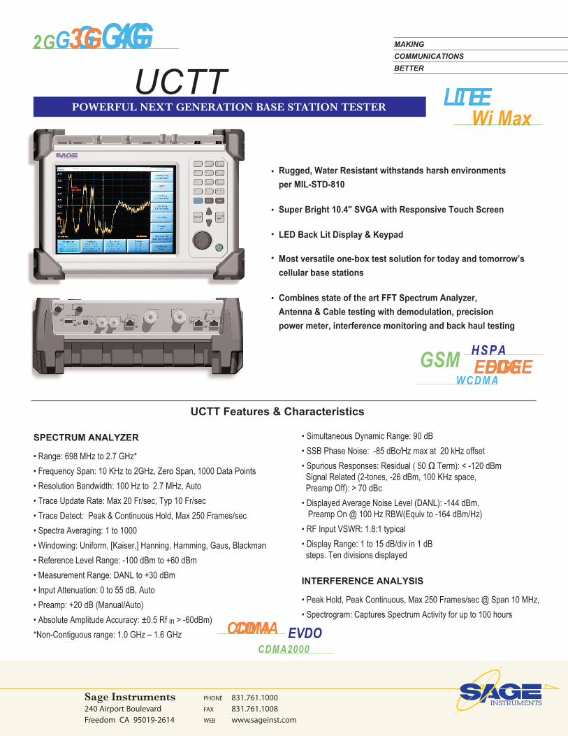
POWERFUL NEXT GENERATION BASE STATION TESTER
240 Airport BoulevardFreedom CA 95019-2614
PHONE 831.761.1000FAX 831.761.1008WEB www.sageinst.com
GSM EDGEEDGEWCDMA
HSPA
Wi MaxLTELTE
G2G 3G 4GG GG
UCTT Features & Characteristics
Rugged, Water Resistant withstands harsh environments per MIL-STD-810
Super Bright 10.4" SVGA with Responsive Touch Screen
LED Back Lit Display & Keypad
Most versatile one-box test solution for today and tomorrow’s cellular base stations
Combines state of the art FFT Spectrum Analyzer, Antenna & Cable testing with demodulation, precision power meter, interference monitoring and back haul testing
•
•
•
•
•
SPECTRUM ANALYZER
• Range: 698 MHz to 2.7 GHz*
• Frequency Span: 10 KHz to 2GHz, Zero Span, 1000 Data Points
• Resolution Bandwidth: 100 Hz to 2.7 MHz, Auto
• Trace Update Rate: Max 20 Fr/sec, Typ 10 Fr/sec
• Trace Detect: Peak & Continuous Hold, Max 250 Frames/sec
• Spectra Averaging: 1 to 1000
• Windowing: Uniform, [Kaiser,] Hanning, Hamming, Gaus, Blackman
• Reference Level Range: -100 dBm to +60 dBm
• Measurement Range: DANL to +30 dBm
• Input Attenuation: 0 to 55 dB, Auto
• Preamp: +20 dB (Manual/Auto)
• Absolute Amplitude Accuracy: ±0.5 Rf in > -60dBm)
*Non-Contiguous range: 1.0 GHz – 1.6 GHz
• Simultaneous Dynamic Range: 90 dB
• SSB Phase Noise: -85 dBc/Hz max at 20 kHz offset
• Spurious Responses: Residual ( 50 Ω Term): < -120 dBm Signal Related (2-tones, -26 dBm, 100 KHz space, Preamp Off): > 70 dBc
• Displayed Average Noise Level (DANL): -144 dBm, Preamp On @ 100 Hz RBW(Equiv to -164 dBm/Hz)
• RF Input VSWR: 1.8:1 typical
• Display Range: 1 to 15 dB/div in 1 dB steps. Ten divisions displayed
INTERFERENCE ANALYSIS
• Peak Hold, Peak Continuous, Max 250 Frames/sec @ Span 10 MHz,
• Spectrogram: Captures Spectrum Activity for up to 100 hours
CDMACDMA EVDOCDMA2000

CABLE AND ANTENNA ANALYZER • Frequency Range: 698 MHz to 2.7 GHz* • Frequency Resolution: 10 KHz & 1 MHz• Interference Immunity: On-Channel: 18 dBm @ > 1.0 MHz from carrier On-Frequency: + 10 dBm within 100 KHz of carrier • Insertion Loss: One Port & Two Port VNA• Insertion Loss Range: <80 dB Accuracy: ± .5 dB, ≥ 80 dB Accuracy: ±5 dB, Scale: 0-60 dB• RFout +5 dBm• Distance-to-Fault Range: 200 M Data Points: 1024 Accuracy: Typical ± 8 cm Measurement Speed: Max < 1 sec • Return Loss: Range: 0 to 100 dB Resolution: 0.01 dB • Accuracy: RL ≤, 25 dB, ± 1.0 dB• 25 dB < RL ≤, 60 dB, ± 3 dB• RL ≥ 60 dB, ± 5 dB• VSWR: Range: 1 to 3.5 Resolution: 0.01 dB
POWER METER • Frequency Range: 698 MHz to 2.7 GHz* • Display Range: -80 dBm to +80 dBm • Measurement Range: -60 dBm to +30 dBm Offset Range: 0 to +60 dB • Accuracy: ± 0.25 dB (RFin > -20 dBm)• VSWR: < 1.8:1 typical • Maximum Power: +30 dBm (1W) without external attenuator • Attenuation Offset Range: -20 to +80 dB
ADJACENT CHANNEL POWER • Frequency Range: 698 MHz to 2.7 GHz* • Measurement Range: +30 dBm to -144 dBm • Channel Power Accuracy: ±1.0 dB • Adjacent Channel Power Accuracy: ±0.50 dBc • Occupied Bandwidth Accuracy: ±100 kHz CHANNEL SCANNER• Simultaneous Channels: 1 to 20• Frequency Range: 68 MHz to 2.7 GHz*• Level Accuracy ± 0.5 dB (RFin > -60 dBm)• Level Range: - 30 dBm to 120 dBm
GSM/EDGE ANALYZERGSM/EDGE Modulation Quality • RMS Phase Measurement Accuracy: ±1 deg • Peak Phase Measurement Accuracy: ±1 deg • Residual Error (GSMK): 1 deg • Frequency Offset Accuracy: ±1 Hz • TSC: 0-7 • SBC: 0-2
*Non-Contiguous range: 1.0 GHz – 1.6 GHz
• Burst Type Capture: Frequency Correction, Dummy, Normal, Synchronization, Access• (EVM) Measurement Accuracy: ±1.5% • Residual Error (8PSK): 2.5% • Frequency Offset Accuracy: ±1 Hz GSM/EDGE Contellation • IQ Diagram • Burst Type Decode • Frame Number Decode • BSIC Number Decode GSM/EDGE BURST ANALYZER TimeSlot Mask per 3GPP-TS-05.05
GSM Mask Support for all Mask Templates per Annex B • Reference Power Level: -90 dBm to +58 dBm
WCDMA/HSPA ANALYZERDemodulator Summary • Code Domain Diagram• Scrambling Detection: Manual, [Auto]• Active Code Channel Detection Threshold: • Manual, [Auto]• OVSF: 2, 4, 8, 16, 32, 64, 128, 256, 512 • Scrambling Code • Frequency Offset • Channel Power• EVM • Rho • PSCH • SSCH • CPICH • P-CCPCH• S-CCPCH • PICH • IQ Offset • Peak CD Error• Noise Floor • EVM AccuracyScrambling Code Scanner• Displays Up to 7 Scrambling Code Pilots• Pilot Dominance • Ec/Io• Total Channel PowerWCDMA Constellation • IQ Multi-Stage Constellation DiagramSpectral Emission Mask CDMA One/CDMA 2000/EVDO Analyzer• RF Spectrum (Rev 0,A,B & C)• CDMA Signal Type Auto Detection• Filtered Signal Trace• Channel Power• Frequency Error• Occupied Bandwidth
CDMAOne/CDMA2000 Summary• Walsh Codes: 62, 128• Code Doman Diagram• Total Power • Rho• IQ Offset • Frequency Offset• Code Channel Utilization (%) • Tau
P O W E R F U L N E X T G E N E R A T I O N B A S E S T A T I O N T E S T E RUCTT
continued
240 Airport Boulevard Freedom, CA 95019-2614 PHONE: 831.761.1000 FAX: 831.761.1008 WEB: www.sageinst.com
MAKING
COMMUNICATIONS
BETTER

MAKING
COMMUNICATIONS
BETTER
EVDO Summary • Walsh Codes: 62, 128• MAC Code Domain Diagram• Data Channel IQ Power Diagram• Data Activity • Modulation Type • Pilot Power & Rho • MAC Power & Rho• Data Power & Rho • Overall Power & Rho• Frequency Offset • IQ Offset (dBc)• Noise Floor dB) • Pilot Ec/Io (dB)• PN Offset • TauMultipath Analyzer• Main Power • Multipath Power• Displays 32 ChipPN Scanner• Pilot • Pilot Dominance• Ec/Io • PN Delay (Chips offset)• Total Channel PowerLTE ANALYZER• Channel Bandwidth: 1.4, 3, 5, 10, 15*, 20* MHz • Cell ID, Sector ID, Group ID.• RS Signal Level (dBm) and correlation Coefficient• P-SS Signal level (dBm) and Correlation Coefficient• S-SS Signal level (dBm) and Correlation Coefficient• PDSCH Signal Level (dBm) and EVM• PBCH Signal Level (dBm) and EVM• PMCH Signal Level (dBm) and EVM• PCFICH Signal Level (dBm) and EVM• PDCCH Signal Level (dBm) and EVM• PHICH Signal Level (dBm) and EVM• Frequency Offset (Hz)• Total Average Channel Power (dBm)• Carrier feed through (dB)• Carrier frequency offset (Hz)• Occupied Bandwidth Measurement Screens: Summary, Symbol Power (Resource Block Selection), Sub-Carrier Spectrogram,IQ Modulation DiagramWiMax Analyzer Channel Bandwidth: 1.25, 1.5, 1.75, 2.5, 3, 3.5, 5, 5.5, 6, 7, 8.75, 10, 12*, 14*, 15*, 17.5*, 20* MHz • Base Station ID• Channel Power (dBm)• Burst Power (dBm)• Preable Power (dBm)• Occupied Bandwidth• EVM (RMS, Peak)• Frequency Error (Hz,ppm)• Relative Constellation Error (RMS, Peak)
* Requires Option 0231
Measurement Screens: Summary, IQ Modulation Diagram, Spectrum (Time/Freq Domain)Protocol AnalyzersGSM ABIS MONITOR • Codec Type: GSM, AMR, ACELP • TRAU FRAME Decode • LAPD Decode Backhaul AnalyzersT1/E1 Analyzer • Fractional T1/E1 and Sub-channels(DS0) • Line Coding: AMI, B8ZS • Framing Modes: D4 (Superframe), ESF (Extended Superframe) • Connection Configurations: Terminate (100 O) Bridge (100K O) Monitor (100 O) Drop&Insert (100 O) • Receiver Sensitivity: Terminate +6 dB to -36 dB Bridge +6 dB to -36 dB Monitor 20 dB flat gain Drop&Insert +6 dB to -36 dB • Transmit Level: 0 dB, -7.5 dB, and -15 dB • Clock Sources: External Bits clock • Internal: 1.544 Mb/s ±5 ppm / 2.048 Mb/s / ±5 ppm • Pulse Shapes: Conform to ANSI T1.403 and ITU G.703 • Pattern Generation and Detection: • PRBS: 2-9, 2-11, 2-15, 2-20, 2-23 Inverted and non-inverted QRSS, 1-in-8 (1-in-7), 2-in-8, 3-in-24, All ones, All zeros, T1-Daly, User defined (128 bits) • Pulse Capture• Circuit Status Reports: Carrier present, Frame ID and Sync., Pattern ID and Sync. • Alarm Detection: AIS, RAI • Error Detection: Frame Bits, Bit, BER, BPV, CRC, Error Sec • Error Insertion: Bit, BPV, Framing Bits, RAI, AIS• Error Events Log and Time Stamp • Loopback Modes: Self loop, CSU, NIU, User defined, In-band or Data Link • Level Measurements: Vp-p (±5%), can also display in dBdsx • Data Log: Continuous, up to 48 hrs • T1 Frequency Measurement: ±5 ppm • DS0 Channel Access Testing: Tone Generator Frequency: 100 Hz to 3000 Hz • Level: -30 to 0 dBm, with 1 dB steps • VF Measurement: Frequency: 100 Hz to 3000 Hz, ±1 Hz Level: -40.0 to +3.0 dBm, ±0.2 dBm • Audio Monitor: Manually select channel 1 to 24 • ITU G.826 Analysis & G.821 Error Reporting: Errored seconds, error free seconds, severely errored seconds, unavailable seconds, available seconds, degraded minutes
P O W E R F U L N E X T G E N E R A T I O N B A S E S T A T I O N T E S T E RUCTT
240 Airport Boulevard Freedom, CA 95019-2614 PHONE: 831.761.1000 FAX: 831.761.1008 WEB: www.sageinst.com
continued

Ethernet Analyzer
• Physical Layer 10/100/1000 Base T
• RFC 2544 /ITU-T Y.156am
• (Throughput, Latency & Packet Loss Rate)Cable Testing (TDR)
ARBITRARY RF SIGNAL GENERATOR
• Frequency Range: 698 MHz to 2.7 GHz *
• Power Output: 0 dBm, ± 1dB
• Phase Noise: 85 dBc
• Waveforms: AMPS, TDMA, GSM, CDMA, WDCMA, LTE, WiMax
GENERAL SPECIFICATIONS
• Uplink/Downlink Channel Plans:
AMPS, CDMA, GSM, UMTS, LTE (EUTRA) BANDS
• Maximum Continuous Input: +30 dBm
• Maximum Continuous Input without Damage: +33 dBm
• Turning Resolution: 1 Hz
• Frequency Accuracy:
Internal Time Base Accuracy: ± 0.1 ppm after warm up
Internal Time Base Aging: ± 0.1 ppm/year GPS Lock:
±1.0 ppb (25° C), Hold-over < 25 ppb (72 hrs)
• Frequency and Time Reference:
InternalReference: GPS derived 1 pps
External: One Pulse Per Second, Even Second Clock
Multiples of 1 MHz to 20 MHz
Multiples of 1.2288 MHz to 19.6608 MHz 2.048 MHz
• Remote Control: Command Line & GUI Emulation
• Interfaces: RF Out Port: Type-N F (50Ω)
RFin Port: Type-N F (50Ω)
• Ext Ref: BNC
• Even Sec/Ext Trig: BNC
• GPS Antenna: SMB
• On-board Memory: 4 GB
• Dual E1/T1: RJ-45
• Dual 10/100/1000: RJ-45 10/100 Base T
Ethernet: RJ-45
• Ext DC Input: MIL-57D Circular
• Audio: MIL-STD Circular (Acc)
*Non-Contiguous range 1.0 GHz - 1.6 GHz
P O W E R F U L N E X T G E N E R A T I O N B A S E S T A T I O N T E S T E RUCTT
240 Airport Boulevard Freedom, CA 95019-2614 PHONE: 831.761.1000 FAX: 831.761.1008 WEB: www.sageinst.com
USB Slave: Type-A
USB Host: Type-B
• Environmental: MIL-STD-810-F
Operating: -20 °C to 55 °C, humidity 85%
Storage: -51-C to 71° C
Altitude: 5000m (16,404 ft)
• Safety: EN 61010-1, portable equipment
• Electromagnetic Compatibility: CE
• Power: 1 or 2 Lithium Batteries
• Battery Life: One Battery 3-4 hr, Two Batteries 7-8 hrs
• Size: 300 x 216 x 114 mm (13.0 x 8.5 x 4.5 in.)
• Weight:
+ One Bat: 6.03 Kg (13.3 lbs)
+ Two Bat: 6.58 (14.5 lbs)
+ Bumpers: 0.59 Kg (1.3 lbs)
UCTT OPTIONS
Part Number Description
8901-0000-01 Base Unit
8901-0010-01 GPS Receiver (with Antenna)8901-0020-01 E1/T1 Back Haul Testing (BERT)8901-0030-01 GigE Analyzer and RF2544 Tester8901-0040-01 Bias Tee Adapter8901-0100-01 FFT Spectrum Analyzer8901-0110-01 Antenna & Cable Analyzer [RL,DTF,& Insertion Loss]8901-0120-01 Power Meter8901-0130-01 Channel Scanner8901-0140-01 Interference Monitor
8901-0150-01 Adjacent Channel Power8901-0210-01 GSM/Edge Analyzer8901-0220-01 W-CDMA/HSPA Analyzer8901-0230-01 LTE Analyzer8901-0231-01 LTE BW 15 & 20 MHz8901-0240-01 CDMAOne/CDMA2000/EVDO Analyzer8901-0250-01 WiMax Analyzer8901-0251-01 WiMax BW 12,14,15,17.5 & 20 MHz
8901-0300-01 GSM MAP Protocol Monitor (T1/E1)8901-0310-01 RF Coverage Mapping
MAKING
COMMUNICATIONS
BETTER