mtk manual pg1
TRANSCRIPT
Monster Tower, Inc.5714 Hwy 411SMaryville, TN 37801
Reference 13-4 July 2012 pg.1 of 8Copyright 2012 Monster Tower, Inc.
Installation Instructions and Owners Manual MTK
Thank you for your purchse. If you are not completely satistied in any way with your new MTK, please contact us immediately. Our entire purpose as a company is to create great products at affordable prices that our customers love.
Phone: 877-778-6937Fax: 877-232-6535
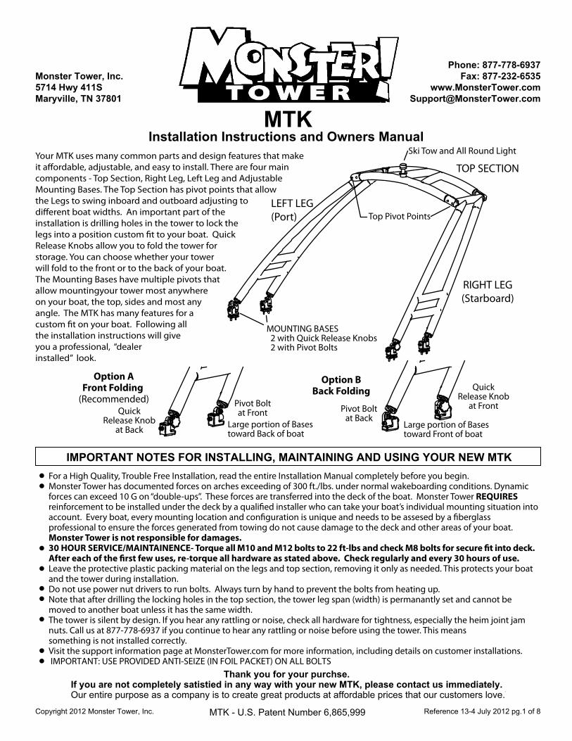
Your MTK uses many common parts and design features that make it a�ordable, adjustable, and easy to install. There are four main components - Top Section, Right Leg, Left Leg and Adjustable Mounting Bases. The Top Section has pivot points that allow the Legs to swing inboard and outboard adjusting to di�erent boat widths. An important part of the installation is drilling holes in the tower to lock the legs into a position custom �t to your boat. Quick Release Knobs allow you to fold the tower for storage. You can choose whether your tower will fold to the front or to the back of your boat. The Mounting Bases have multiple pivots that allow mountingyour tower most anywhere on your boat, the top, sides and most any angle. The MTK has many features for a custom �t on your boat. Following all the installation instructions will give you a professional, “dealer installed” look.
Large portion of Basestoward Back of boat
Option AFront Folding
(Recommended)Quick
Release Knobat Back
Pivot Boltat Front
QuickRelease Knob
at FrontPivot Boltat Back
Option BBack Folding
Large portion of Basestoward Front of boat
RIGHT LEG(Starboard)
LEFT LEG(Port)
TOP SECTION
Top Pivot Points
Ski Tow and All Round Light
MOUNTING BASES 2 with Quick Release Knobs 2 with Pivot Bolts
IMPORTANT NOTES FOR INSTALLING, MAINTAINING AND USING YOUR NEW MTKFor a High Quality, Trouble Free Installation, read the entire Installation Manual completely before you begin.Monster Tower has documented forces on arches exceeding of 300 ft./lbs. under normal wakeboarding conditions. Dynamic forces can exceed 10 G on “double-ups”. These forces are transferred into the deck of the boat. Monster Tower REQUIRES reinforcement to be installed under the deck by a quali�ed installer who can take your boat’s individual mounting situation into account. Every boat, every mounting location and con�guration is unique and needs to be assesed by a �berglass professional to ensure the forces generated from towing do not cause damage to the deck and other areas of your boat. Monster Tower is not responsible for damages. 30 HOUR SERVICE/MAINTAINENCE- Torque all M10 and M12 bolts to 22 ft-lbs and check M8 bolts for secure �t into deck. After each of the �rst few uses, re-torque all hardware as stated above. Check regularly and every 30 hours of use.Leave the protective plastic packing material on the legs and top section, removing it only as needed. This protects your boat and the tower during installation. Do not use power nut drivers to run bolts. Always turn by hand to prevent the bolts from heating up.Note that after drilling the locking holes in the top section, the tower leg span (width) is permanantly set and cannot be moved to another boat unless it has the same width. The tower is silent by design. If you hear any rattling or noise, check all hardware for tightness, especially the heim joint jam nuts. Call us at 877-778-6937 if you continue to hear any rattling or noise before using the tower. This means something is not installed correctly.Visit the support information page at MonsterTower.com for more information, including details on customer installations. IMPORTANT: USE PROVIDED ANTI-SEIZE (IN FOIL PACKET) ON ALL BOLTS
MTK - U.S. Patent Number 6,865,999
Reference 13-4 July 2012 pg.2 of 8Copyright 2012 Monster Tower, Inc.
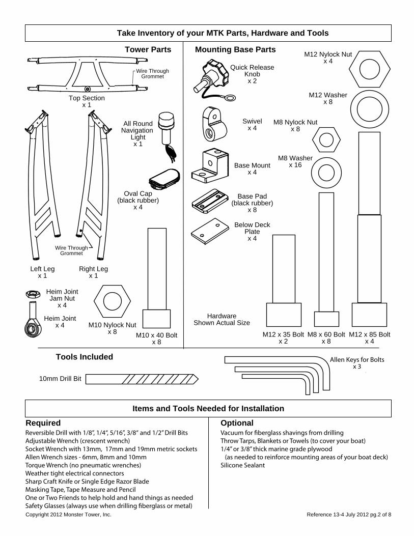
Take Inventory of your MTK Parts, Hardware and Tools
Tower Parts Mounting Base Parts
Top Sectionx 1
Right Legx 1
Left Legx 1
Wire ThroughGrommet
Wire ThroughGrommet
Heim JointJam Nut
x 4
Heim Jointx 4
All RoundNavigation
Lightx 1
Swivelx 4
Base Mountx 4
Below DeckPlatex 4
Quick ReleaseKnobx 2
Base Pad(black rubber)
x 8
M10 x 40 Boltx 8
HardwareShown Actual Size
M12 x 35 Boltx 2
M8 x 60 Boltx 8
M12 x 85 Boltx 4
M10 Nylock Nutx 8
M12 Nylock Nutx 4
M8 Nylock Nutx 8
M8 Washerx 16
M12 Washerx 8
Tools Included
10mm Drill Bit
Items and Tools Needed for Installation
Required OptionalVacuum for �berglass shavings from drillingThrow Tarps, Blankets or Towels (to cover your boat) 1/4” or 3/8” thick marine grade plywood (as needed to reinforce mounting areas of your boat deck)Silicone Sealant
Reversible Drill with 1/8”, 1/4“, 5/16”, 3/8“ and 1/2” Drill BitsAdjustable Wrench (crescent wrench)Socket Wrench with 13mm, 17mm and 19mm metric socketsAllen Wrench sizes - 6mm, 8mm and 10mmTorque Wrench (no pneumatic wrenches)Weather tight electrical connectorsSharp Craft Knife or Single Edge Razor BladeMasking Tape, Tape Measure and PencilOne or Two Friends to help hold and hand things as neededSafety Glasses (always use when drilling �berglass or metal)
Oval Cap(black rubber)
x 4
Allen Keys for Boltsx 3
Reference 13-4July 2012 pg.3 of 8Copyright 2012 Monster Tower, Inc.
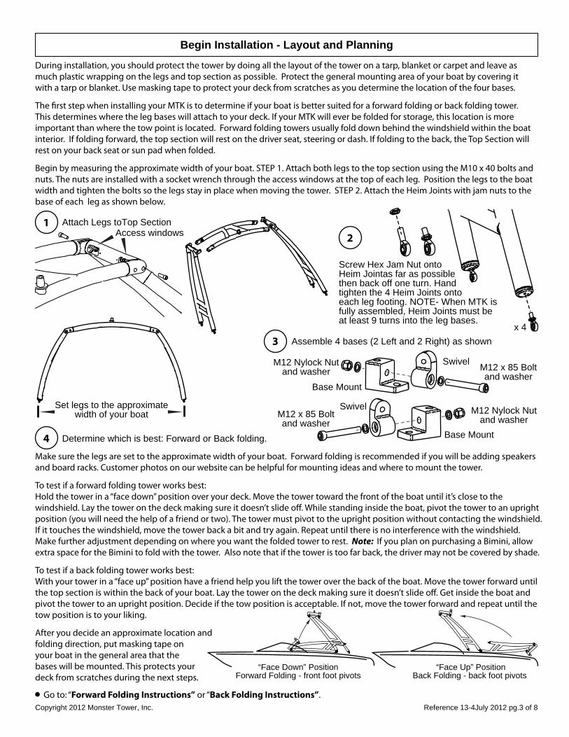
2
x 4
Screw Hex Jam Nut onto Heim Jointas far as possible then back off one turn. Hand tighten the 4 Heim Joints ontoeach leg footing. NOTE- When MTK isfully assembled, Heim Joints must be at least 9 turns into the leg bases.
3
Attach Legs toTop Section1
Begin Installation - Layout and Planning
During installation, you should protect the tower by doing all the layout of the tower on a tarp, blanket or carpet and leave as much plastic wrapping on the legs and top section as possible. Protect the general mounting area of your boat by covering it with a tarp or blanket. Use masking tape to protect your deck from scratches as you determine the location of the four bases.
The �rst step when installing your MTK is to determine if your boat is better suited for a forward folding or back folding tower. This determines where the leg bases will attach to your deck. If your MTK will ever be folded for storage, this location is more important than where the tow point is located. Forward folding towers usually fold down behind the windshield within the boat interior. If folding forward, the top section will rest on the driver seat, steering or dash. If folding to the back, the Top Section will rest on your back seat or sun pad when folded.
Begin by measuring the approximate width of your boat. STEP 1. Attach both legs to the top section using the M10 x 40 bolts and nuts. The nuts are installed with a socket wrench through the access windows at the top of each leg. Position the legs to the boat width and tighten the bolts so the legs stay in place when moving the tower. STEP 2. Attach the Heim Joints with jam nuts to the base of each leg as shown below.
Set legs to the approximatewidth of your boat
Access windows
Assemble 4 bases (2 Left and 2 Right) as shown
M12 x 85 Boltand washer
Base Mount
Base Mount
M12 x 85 Boltand washer
M12 Nylock Nutand washer
M12 Nylock Nutand washer
Swivel
Swivel
4Make sure the legs are set to the approximate width of your boat. Forward folding is recommended if you will be adding speakers and board racks. Customer photos on our website can be helpful for mounting ideas and where to mount the tower.
To test if a forward folding tower works best:Hold the tower in a “face down” position over your deck. Move the tower toward the front of the boat until it’s close to the windshield. Lay the tower on the deck making sure it doesn’t slide o�. While standing inside the boat, pivot the tower to an upright position (you will need the help of a friend or two). The tower must pivot to the upright position without contacting the windshield. If it touches the windshield, move the tower back a bit and try again. Repeat until there is no interference with the windshield. Make further adjustment depending on where you want the folded tower to rest. Note: If you plan on purchasing a Bimini, allow extra space for the Bimini to fold with the tower. Also note that if the tower is too far back, the driver may not be covered by shade.
To test if a back folding tower works best:With your tower in a “face up” position have a friend help you lift the tower over the back of the boat. Move the tower forward until the top section is within the back of your boat. Lay the tower on the deck making sure it doesn’t slide o�. Get inside the boat and pivot the tower to an upright position. Decide if the tow position is acceptable. If not, move the tower forward and repeat until the tow position is to your liking.
After you decide an approximate location andfolding direction, put masking tape on your boat in the general area that the bases will be mounted. This protects your deck from scratches during the next steps.
Determine which is best: Forward or Back folding.
“Face Down” PositionForward Folding - front foot pivots
“Face Up” PositionBack Folding - back foot pivots
Go to: “Forward Folding Instructions” or “Back Folding Instructions”.
Reference 13-4 July 2012 pg.4 of 8Copyright 2012 Monster Tower, Inc.
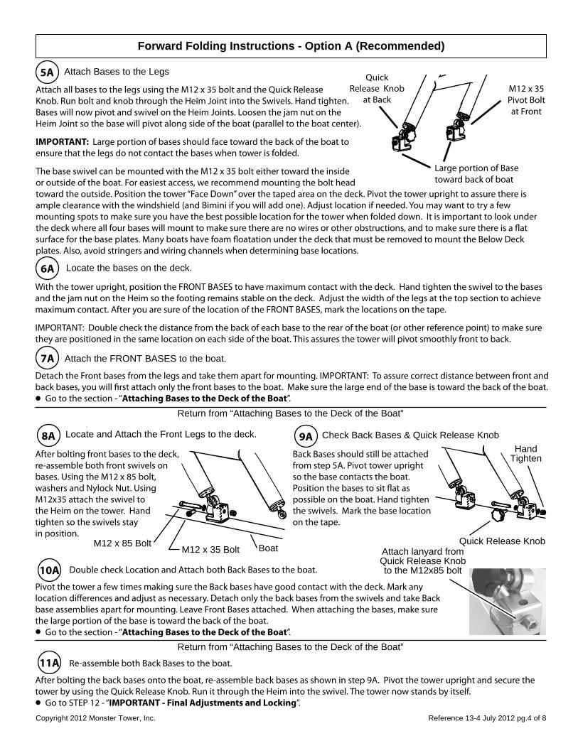
Attach Bases to the Legs5A
Forward Folding Instructions - Option A (Recommended)
Large portion of Basetoward back of boat
QuickRelease Knob
at BackM12 x 35Pivot Boltat Front
Attach all bases to the legs using the M12 x 35 bolt and the Quick Release Knob. Run bolt and knob through the Heim Joint into the Swivels. Hand tighten.Bases will now pivot and swivel on the Heim Joints. Loosen the jam nut on theHeim Joint so the base will pivot along side of the boat (parallel to the boat center).
IMPORTANT: Large portion of bases should face toward the back of the boat to ensure that the legs do not contact the bases when tower is folded.
The base swivel can be mounted with the M12 x 35 bolt either toward the inside or outside of the boat. For easiest access, we recommend mounting the bolt head toward the outside. Position the tower “Face Down” over the taped area on the deck. Pivot the tower upright to assure there is ample clearance with the windshield (and Bimini if you will add one). Adjust location if needed. You may want to try a few mounting spots to make sure you have the best possible location for the tower when folded down. It is important to look under the deck where all four bases will mount to make sure there are no wires or other obstructions, and to make sure there is a �at surface for the base plates. Many boats have foam �oatation under the deck that must be removed to mount the Below Deck plates. Also, avoid stringers and wiring channels when determining base locations.
6AWith the tower upright, position the FRONT BASES to have maximum contact with the deck. Hand tighten the swivel to the bases and the jam nut on the Heim so the footing remains stable on the deck. Adjust the width of the legs at the top section to achieve maximum contact. After you are sure of the location of the FRONT BASES, mark the locations on the tape.
IMPORTANT: Double check the distance from the back of each base to the rear of the boat (or other reference point) to make surethey are positioned in the same location on each side of the boat. This assures the tower will pivot smoothly front to back.
Locate the bases on the deck.
7A Attach the FRONT BASES to the boat.
Detach the Front bases from the legs and take them apart for mounting. IMPORTANT: To assure correct distance between front and back bases, you will �rst attach only the front bases to the boat. Make sure the large end of the base is toward the back of the boat. Go to the section - “Attaching Bases to the Deck of the Boat”.
8A Locate and Attach the Front Legs to the deck.
After bolting front bases to the deck, re-assemble both front swivels on bases. Using the M12 x 85 bolt, washers and Nylock Nut. Using M12x35 attach the swivel to the Heim on the tower. Hand tighten so the swivels stay in position.
M12 x 85 BoltM12 x 35 Bolt Boat
Return from “Attaching Bases to the Deck of the Boat”
9A Check Back Bases & Quick Release Knob
Back Bases should still be attached from step 5A. Pivot tower upright so the base contacts the boat. Position the bases to sit �at aspossible on the boat. Hand tightenthe swivels. Mark the base location on the tape.
Quick Release Knob
10A Double check Location and Attach both Back Bases to the boat.
Pivot the tower a few times making sure the Back bases have good contact with the deck. Mark any location di�erences and adjust as necessary. Detach only the back bases from the swivels and take Back base assemblies apart for mounting. Leave Front Bases attached. When attaching the bases, make sure the large portion of the base is toward the back of the boat. Go to the section - “Attaching Bases to the Deck of the Boat”.
Return from “Attaching Bases to the Deck of the Boat”
11A Re-assemble both Back Bases to the boat.
After bolting the back bases onto the boat, re-assemble back bases as shown in step 9A. Pivot the tower upright and secure the tower by using the Quick Release Knob. Run it through the Heim into the swivel. The tower now stands by itself. Go to STEP 12 - “IMPORTANT - Final Adjustments and Locking”.
Attach lanyard fromQuick Release Knobto the M12x85 bolt
HandTighten
Reference 13-4July 2012 pg.5 of 8Copyright 2012 Monster Tower, Inc.
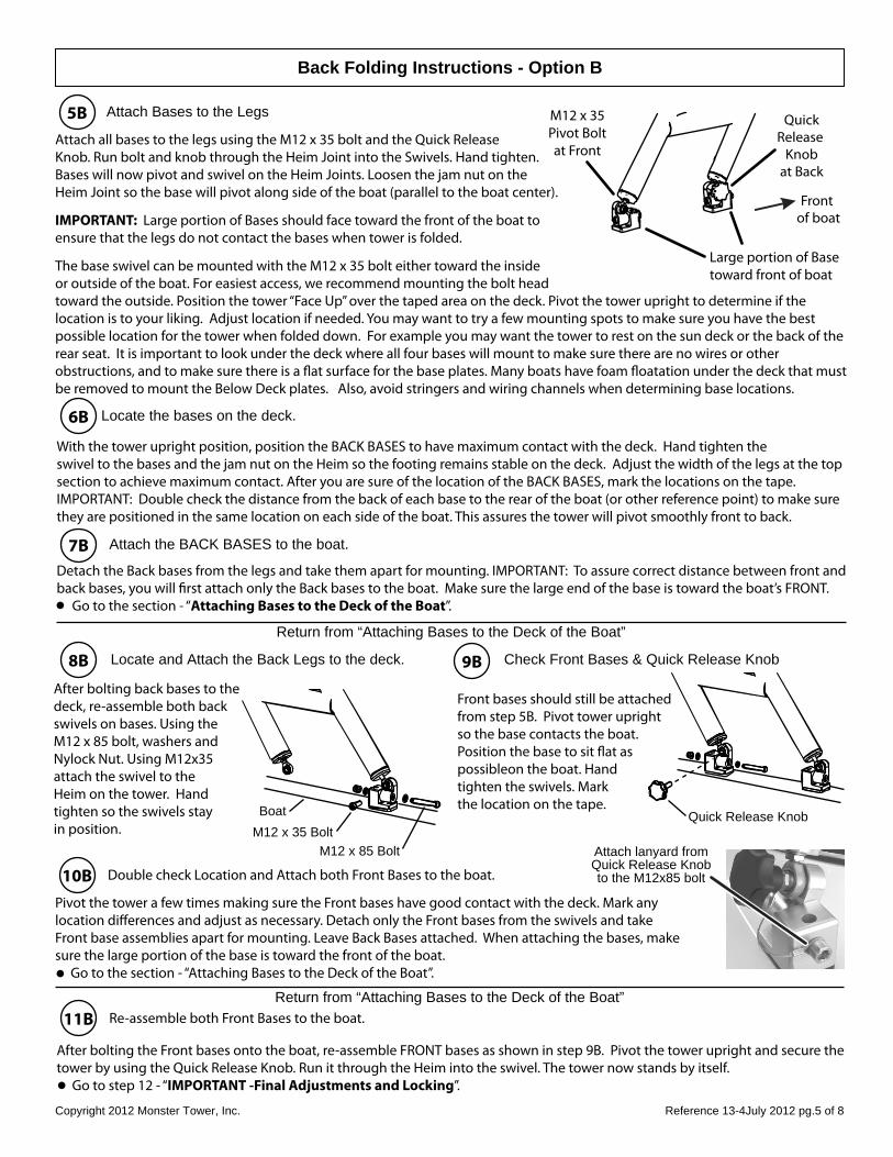
Attach Bases to the Legs5B
Back Folding Instructions - Option B
Large portion of Basetoward front of boat
QuickRelease
Knobat Back
M12 x 35Pivot Boltat Front
Attach all bases to the legs using the M12 x 35 bolt and the Quick Release Knob. Run bolt and knob through the Heim Joint into the Swivels. Hand tighten.Bases will now pivot and swivel on the Heim Joints. Loosen the jam nut on theHeim Joint so the base will pivot along side of the boat (parallel to the boat center).
IMPORTANT: Large portion of Bases should face toward the front of the boat to ensure that the legs do not contact the bases when tower is folded.
The base swivel can be mounted with the M12 x 35 bolt either toward the inside or outside of the boat. For easiest access, we recommend mounting the bolt head toward the outside. Position the tower “Face Up” over the taped area on the deck. Pivot the tower upright to determine if the location is to your liking. Adjust location if needed. You may want to try a few mounting spots to make sure you have the best possible location for the tower when folded down. For example you may want the tower to rest on the sun deck or the back of the rear seat. It is important to look under the deck where all four bases will mount to make sure there are no wires or other obstructions, and to make sure there is a �at surface for the base plates. Many boats have foam �oatation under the deck that must be removed to mount the Below Deck plates. Also, avoid stringers and wiring channels when determining base locations.
Front of boat
6B
With the tower upright position, position the BACK BASES to have maximum contact with the deck. Hand tighten the swivel to the bases and the jam nut on the Heim so the footing remains stable on the deck. Adjust the width of the legs at the top section to achieve maximum contact. After you are sure of the location of the BACK BASES, mark the locations on the tape.IMPORTANT: Double check the distance from the back of each base to the rear of the boat (or other reference point) to make surethey are positioned in the same location on each side of the boat. This assures the tower will pivot smoothly front to back.
Locate the bases on the deck.
7B Attach the BACK BASES to the boat.
Detach the Back bases from the legs and take them apart for mounting. IMPORTANT: To assure correct distance between front andback bases, you will �rst attach only the Back bases to the boat. Make sure the large end of the base is toward the boat’s FRONT. Go to the section - “Attaching Bases to the Deck of the Boat”.
8B Locate and Attach the Back Legs to the deck.
After bolting back bases to the deck, re-assemble both back swivels on bases. Using the M12 x 85 bolt, washers and Nylock Nut. Using M12x35 attach the swivel to the Heim on the tower. Hand tighten so the swivels stay in position.
Return from “Attaching Bases to the Deck of the Boat”
9B Check Front Bases & Quick Release Knob
Front bases should still be attached from step 5B. Pivot tower upright so the base contacts the boat. Position the base to sit �at as possibleon the boat. Hand tighten the swivels. Mark the location on the tape.
10B Double check Location and Attach both Front Bases to the boat.
Return from “Attaching Bases to the Deck of the Boat”11B Re-assemble both Front Bases to the boat.
After bolting the Front bases onto the boat, re-assemble FRONT bases as shown in step 9B. Pivot the tower upright and secure the tower by using the Quick Release Knob. Run it through the Heim into the swivel. The tower now stands by itself. Go to step 12 - “IMPORTANT -Final Adjustments and Locking”.
Pivot the tower a few times making sure the Front bases have good contact with the deck. Mark any location di�erences and adjust as necessary. Detach only the Front bases from the swivels and take Front base assemblies apart for mounting. Leave Back Bases attached. When attaching the bases, make sure the large portion of the base is toward the front of the boat. Go to the section - “Attaching Bases to the Deck of the Boat”.
Attach lanyard fromQuick Release Knobto the M12x85 bolt
M12 x 85 BoltM12 x 35 BoltBoat Quick Release Knob
Reference 13-4July 2012 pg.6 of 8Copyright 2012 Monster Tower, Inc.
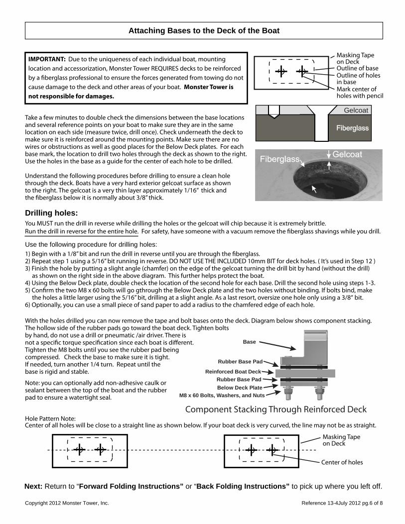
Attaching Bases to the Deck of the Boat
Masking Tapeon DeckOutline of baseOutline of holesin baseMark center ofholes with pencil
Gelcoat
Understand the following procedures before drilling to ensure a clean hole through the deck. Boats have a very hard exterior gelcoat surface as shown to the right. The gelcoat is a very thin layer approximately 1/16” thick and the �berglass below it is normally about 3/8” thick.
IMPORTANT: Due to the uniqueness of each individual boat, mounting location and accessorization, Monster Tower REQUIRES decks to be reinforced by a �berglass professional to ensure the forces generated from towing do not cause damage to the deck and other areas of your boat. Monster Tower is not responsible for damages.
Next: Return to “Forward Folding Instructions” or “Back Folding Instructions” to pick up where you left off.
Hole Pattern Note: Center of all holes will be close to a straight line as shown below. If your boat deck is very curved, the line may not be as straight.
Masking Tapeon Deck
Center of holes
Drilling holes:You MUST run the drill in reverse while drilling the holes or the gelcoat will chip because it is extremely brittle. Run the drill in reverse for the entire hole. For safety, have someone with a vacuum remove the �berglass shavings while you drill.
Use the following procedure for drilling holes:1) Begin with a 1/8” bit and run the drill in reverse until you are through the �berglass. 2) Repeat step 1 using a 5/16” bit running in reverse. DO NOT USE THE INCLUDED 10mm BIT for deck holes. ( It’s used in Step 12 )3) Finish the hole by putting a slight angle (chamfer) on the edge of the gelcoat turning the drill bit by hand (without the drill) as shown on the right side in the above diagram. This further helps protect the boat.4) Using the Below Deck plate, double check the location of the second hole for each base. Drill the second hole using steps 1-3.5) Con�rm the two M8 x 60 bolts will go gthrough the Below Deck plate and the two holes without binding. If bolts bind, make the holes a little larger using the 5/16” bit, drilling at a slight angle. As a last resort, oversize one hole only using a 3/8“ bit.6) Optionally, you can use a small piece of sand paper to add a radius to the chamfered edge of each hole.
With the holes drilled you can now remove the tape and bolt bases onto the deck. Diagram below shows component stacking. The hollow side of the rubber pads go toward the boat deck. Tighten bolts by hand, do not use a drill or pneumatic /air driver. There is not a speci�c torque speci�cation since each boat is di�erent. Tighten the M8 bolts until you see the rubber pad being compressed. Check the base to make sure it is tight. If needed, turn another 1/4 turn. Repeat until the base is rigid and stable.
Note: you can optionally add non-adhesive caulk or sealant between the top of the boat and the rubber pad to ensure a watertight seal.
Base
Rubber Base Pad
Reinforced Boat Deck
Below Deck PlateM8 x 60 Bolts, Washers, and Nuts
Component Stacking Through Reinforced Deck
Rubber Base Pad
Take a few minutes to double check the dimensions between the base locations and several reference points on your boat to make sure they are in the same location on each side (measure twice, drill once). Check underneath the deck to make sure it is reinforced around the mounting points. Make sure there are no wires or obstructions as well as good places for the Below Deck plates. For each base mark, the location to drill two holes through the deck as shown to the right. Use the holes in the base as a guide for the center of each hole to be drilled.
Reference 13-4 July 2012 pg.7 of 8Copyright 2012 Monster Tower, Inc.
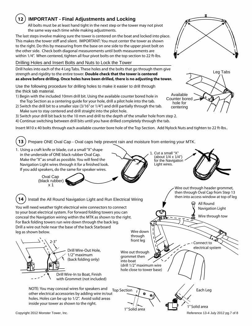
12
14
IMPORTANT - Final Adjustments and LockingAll bolts must be at least hand tight in the next step or the tower may not pivot the same way each time while making adjustments.
The last steps involve making sure the tower is centered on the boat and locked into place. This makes the tower sti� and silent. IMPORTANT: You must center the tower as shown to the right. Do this by measuring from the base on one side to the upper pivot bolt on the other side. Check both diagonal measurements until both measurements are within 1/4”. When centered, tighten all four pivot bolts on the top section to 22 ft-lbs.
Drilling Holes and Insert Bolts and Nuts to Lock the TowerDrill holes into each of the 4 Leg Tabs. These holes and the bolts that go through them give strength and rigidity to the entire tower. Double check that the tower is centered as above before drilling. Once holes have been drilled, there is no adjusting the tower.
Use the following procedure for drilling holes to make it easier to drill through the thick tab material. 1) Begin with the included 10mm drill bit. Using the available counter bored hole in the Top Section as a centering guide for your hole, drill a pilot hole into the tab. 2) Switch the drill bit to a smaller size (3/16” or 1/4“) and drill partially through the tab. Make sure to stay centered and drill straight into the pilot hole. 3) Switch your drill bit back to the 10 mm and drill to the depth of the smaller hole from step 2. 4) Continue switching between drill bits until you have drilled completely through the tab.
Insert M10 x 40 bolts through each available counter bore hole of the Top Section. Add Nylock Nuts and tighten to 22 ft-lbs..
Install the All Round Navigation Light and Run Electrical Wiring
You will need weather tight electrical wire connectors to connect to your boat electrical system. For forward folding towers you can conceal the Navigation wiring within the MTK as shown to the right. For Back folding towers run wire down through the back leg. Drill a wire out hole near the base of the back Starboard leg as shown below.
Drill Wire-Out Hole,1/2” maximum(back folding only)
NOTE: You may conceal wires for speakers and other electrical accessories by adding wire in/out holes. Holes can be up to 1/2”. Avoid solid areas inside your tower as shown to the right.
1” Solid area
Each Leg
1” Solid area
Top Section
2-3”
Drill Wire-In to Boat, Finish with Grommet (not included)
Leg Tabs
AvailableCounter bored
hole forcentering
All RoundNavigation Light
Wire out through header grommet, then through Oval Cap from Step 13 then into access window at top of leg
Wire through tow
Wire down through front leg
Wire out through grommet then into boat (drill 1/2” maximum wire hole close to tower base)
Connect toelectrical system
13 Prepare ONE Oval Cap - Oval caps help prevent rain and moisture from entering your MTK.
1. Using a craft knife or blade, cut a small “X” shape in the underside of ONE black rubber Oval Cap. Make the “X” as small as possible. You will feed the Navigation Light wires through it for a �nished look. If you add speakers, do the same for speaker wires.
Oval Cap (black rubber)
x 1
1. Cut a small “X” (about 1/4 x 1/4”) for the Navigation Light wires.
Reference 13-4 July 2012 pg.8 of 8Copyright 2012 Monster Tower, Inc.
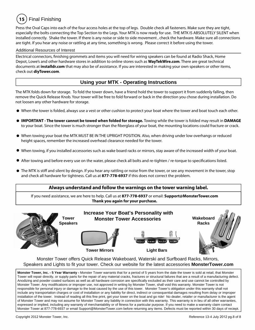
Monster Tower offers Quick Release Wakeboard, Waterski and Surfboard Racks, Mirrors, Speakers and Lights to fit your tower. Check our website for the latest accessories MonsterTower.com
If you need assistance, we are here to help. Call us at 877-778-6937 or email: [email protected] you again for your purchase.
Always understand and follow the warnings on the tower warning label.
Monster Tower, Inc. - 5 Year Warranty - Monster Tower warrants that for a period of 5 years from the date the tower is sold at retail, that MonsterTower will repair directly, or supply parts for the repair of any material cracks, fractures or structural failures that are a result of a manufacturing defect.Anodizing and powder coated surfaces as well as all hardware corrosion are specifically excluded as their care and use cannot be controlled by Monster Tower. Any modifications or improper use, not approved in writing by Monster Tower, shall void this warranty. Monster Tower is not responsible for personal injury or damage to the boat caused by the use of this tower. Monster Tower’s obligation under this warranty shall not include any transportation charges or cost of installation or any liability for direct, indirect or consequential damages resulting from delay or improper installation of the tower. Instead of reading all this fine print, get your tower on the boat and go ride! No dealer, retailer or manufacturer is the agent of Monster Tower and may not assume for Monster Tower any liability in connection with this warranty. This warranty is in lieu of all other warranties,expressed or implied, including any warranty of merchantability or of fitness for a particular purpose. If you need to make a warranty claim contact Monster Tower at 877-778-6937 or email [email protected] before returning any items. Defects must be reported within 30 days of reciept.
Using your MTK - Operating Instructions
The MTK folds down for storage. To fold the tower down, have a friend hold the tower to support it from suddenly falling, then remove the Quick Release Knob. Your tower will be free to fold forward or back in the direction you chose during installation. Do not loosen any other hardware for storage.
When the tower is folded, always use a vest or other cushion to protect your boat where the tower and boat touch each other.
IMPORTANT - The tower cannot be towed when folded for storage. Towing while the tower is folded may result in DAMAGE to your boat. Since the tower is much stronger than the �berglass of your boat, the mounting locations could fracture or crack.
When towing your boat the MTK MUST BE IN THE UPRIGHT POSITION. Also, when driving under low overhangs or reduced height spaces, remember the increased overhead clearance needed for the tower.
When towing, if you installed accessories such as wake board racks or mirrors, stay aware of the increased width of your boat.
After towing and before every use on the water, please check all bolts and re-tighten / re-torque to speci�cations listed.
The MTK is sti� and silent by design. If you hear any rattling or noise from the tower, or see any movement in the tower, stop and check all hardware for tightness. Call us at 877-778-6937 if this does not correct the problem.
15 Final Finishing
Press the Oval Caps into each of the four access holes at the top of legs. Double check all fasteners. Make sure they are tight, especially the bolts connecting the Top Section to the Legs. Your MTK is now ready for use. THE MTK IS ABSOLUTELY SILENT when installed correctly. Shake the tower. If there is any noise or side to side movement , check the hardware. Make sure all connections are tight. If you hear any noise or rattling at any time, something is wrong. Please correct it before using the tower.
Additional Resources of InterestElectrical connectors, �nishing grommets and items you will need for wiring speakers can be found at Radio Shack, Home Depot, Lowe’s and other hardware stores in addition to online stores such as WayTekWire.com. There are great technical documents at installdr.com that may also be of assistance. If you are interested in making your own speakers or other items, check out diyTower.com.
Increase Your Boat’s Personality withMonster Tower Accessories Wakeboard
Racks
Light Bars
TowerSpeakers
Tower Mirrors