ucg modelling 14nov06 - energy.gov
TRANSCRIPT

UCG Modelling
14th November 2006
Kolkata, India
Dr Andrew Beath
CSIRO Exploration & Mining
Australia
Dr Cliff Mallett
Carbon Energy Pty Ltd
Australia

Modelling of UCG processes
UCG research involves analysis of a complex system of interacting:
oGeological factors
oGasification process
oSurface and groundwater impacts
oPublic perceptions
Most published models are limited to an analysis of only a part of the process.
This presentation also will be limited to modellingthe cavity growth through reaction processes, but a companion presentation discusses modelling of the physical site changes.

Reaction Processes
Product gas
Drying, Volatile release &
Gasification
Drying & Volatile release
Combustion&
High temperatures
Gas reduction&
Moderate temperatures
Gas equilibrium reactions& Cooling
Drying
Feed gas

Literature models
Selected published models
o CAVSIM (Lawrence Livermore)
o CFD (Delft Univ. of Technology)
o Box (European Community)
Numerous 1-dimensional models have been published with relatively minor differences

CAVSIM-Lawrence Livermore
Assumes the gasification cavity will be axisymmetrical around a vertical axis
Developed to model CRIP experiments performed in the USA
Limited reaction set, heat transfer and gas flow
Cavity growth is by ‘spalling’, where material falls off the roof and walls

CAVSIM geometry
Ash rubble
Charrubble
Rock rubble
Void space

CAVSIM summary
CAVSIM was used successfully to model specific experiments, but was hindered by the difficulty in
estimating the ‘spalling’ rate until after the experiment was performed and required
corrections when the geometry was disturbed by shortening of
the CRIP

CFD-Delft Univ. of TechnologySeries of models developed for the European Community gasification trials
Considered the site as being composed of numerous finite elements of coal that increased in porosity with reaction
Simplifying assumptions include constant block temperature and pre-defined gas flow path, but vary between model versions

Delft example
Void Ash/Spalled region
Biezen (1996) produced a model which allowed collapse of material when the porosity becomes excessive. Some factors require fitting to experimental data. The example shown below is based on the Rocky Mountain 1 trial.

Delft summary
The Delft approach is extremely numerically intensive. Several
different models have been published, but they all require
simplifying assumptions to allow solutions to be achieved. For
example, an average temperature may be used for all coal in the
region of the void.

Box models-European Comm.
Simplified models that involve zones with pre-defined roles, for example:
o First box is a combustion zone
o Second box has other gasification reactions
o Third box allows gas bypass of reactions
Generally, the product gas is assumed to be at equilibrium at an assumed exit temperature

2-Box model (Dufaux, 1990)

Box model comments
This type of modified equilibrium model is useful for rapid predictions
Definition of the boxes is fairly arbitrary and can vary with gasification technique and site characteristics
There is a tendency to increase the number of boxes to improve alignment with experimental results, but this makes it more a correlation than a model

CSIRO modelling
We have taken a more comprehensive approach to
UCG, considering not only the gasification process but also
the geotechnical and hydrology interactions. This requires a suite of models, rather than a
single model.

Modelling suite for UCG
Coal model Cavity model
Geotechnical model
Regional hydrology model
Process simulation

Elements of the Coal & Cavity models for UCG
Coal & char reactionsCoal/char structural changesGas flow and reactionsWater flows and evaporationHeat transfer o Conduction, convection & radiation
Rock & coal breakage and collapseResizing of the matrix with growth
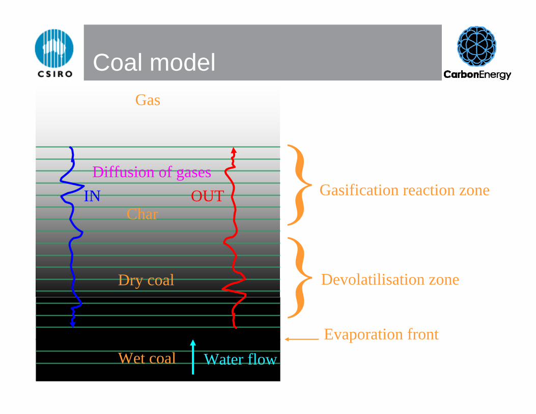
Coal modelGas
Evaporation front
Dry coal
Wet coal
Diffusion of gasesIN OUT
Char
Devolatilisation zone
Gasification reaction zone
Water flow

Output from coal model
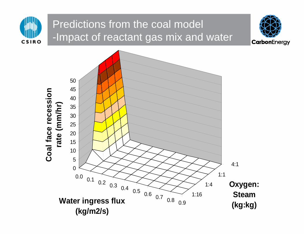
Predictions from the coal model-Impact of reactant gas mix and water
0.0 0.1 0.2 0.3 0.4 0.5 0.6 0.7 0.8 0.91:16
1:4
1:1
4:105
101520253035404550
Coa
l fac
e re
cess
ion
rate
(mm
/hr)
Water ingress flux (kg/m2/s)
Oxygen:Steam (kg:kg)

Predictions from the coal model-Impact of pressure and temperature
1000
1100
1200
1300
1400
1500
1600
1700
1800
1900
1
10
40
1000
50
100
150
200
250
Coa
l fac
e re
cess
ion
rate
(mm
/hr)
Gas temperature (K)
Pressure (atm)

Use of the coal model
Does not provide standalone predictions relevant to UCG as it neglects many of the gas flow and heat transfer features of real cavities
Makes spot predictions of coal behaviour under pseudo-steady state conditions to feed into more complex models
Can be used to predict the general operating regimes that are desirable for efficient gasification

Cavity model
Rubble
‘Slab’ outline
Rock floor
Rock roof
Evaporation front
Gas

Cavity model operation3D model of CRIP3D model of CRIP--type reactortype reactorInjection and production points can Injection and production points can move with cavity growthmove with cavity growthIncludes chemical, heat transfer and Includes chemical, heat transfer and flow processesflow processes
Display accelerated for Display accelerated for presentation purposespresentation purposes
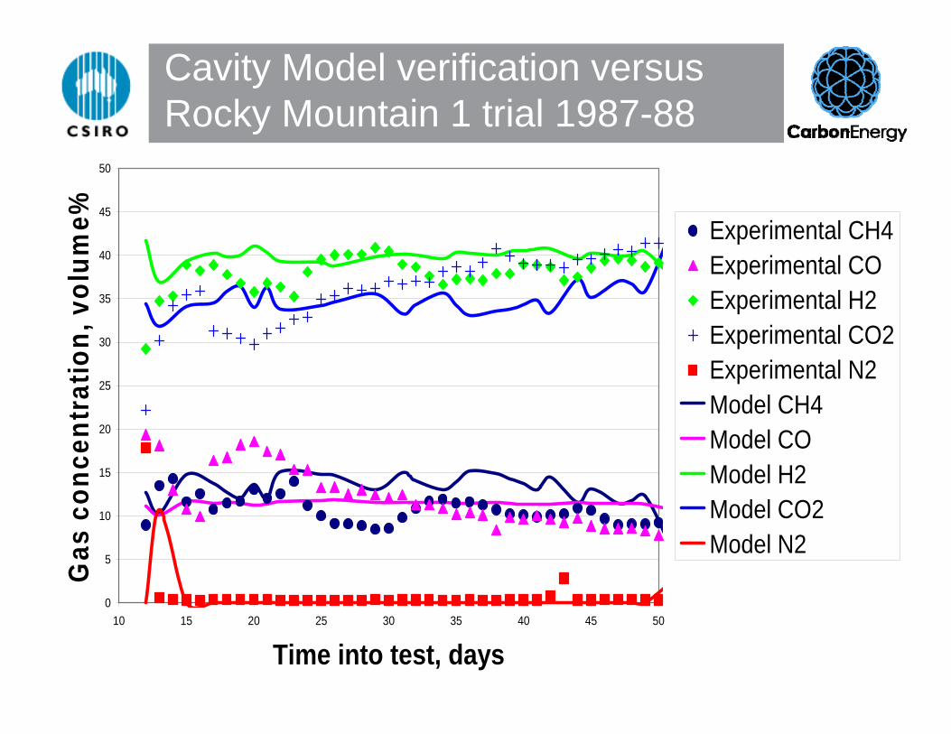
Cavity Model verification versus Rocky Mountain 1 trial 1987-88
0
5
10
15
20
25
30
35
40
45
50
10 15 20 25 30 35 40 45 50
Time into test, days
Gas
con
cent
ratio
n, v
olum
e% Experimental CH4Experimental COExperimental H2Experimental CO2Experimental N2Model CH4Model COModel H2Model CO2Model N2

Model performancePredicts accurately:
o Cavity volume changes
o Product gas composition and flow
Hindrances to model performance:o Requires detailed site information
o Experimentally, the cavity shape was affected by uncontrolled shortening of the ‘CRIP’ and an undetected fault running through the site

Other models
Geotechnical - COSFLOW is a CSIRO developed model for rock collapse, water flow, contaminant flow and gas flow in mining affected strata.
Regional hydrology – MODFLOW is a public domain modelling platform for large scale hydrological simulation.
Process simulation – HYSYS.Process is commercial software package that can be used to simulate power production and chemical production from UCG product gas.

Summary
There have been numerous published models relating to UCG, however, it is
apparent that the interaction of the underground reactions with the
geological ‘container’ requires a more comprehensive approach that
includes the

14th November 2006
Kolkata, India
Dr Andrew Beath
CSIRO Exploration & Mining
Dr Cliff Mallett
Carbon Energy Pty Ltd
Australia
The End