ucan tech manual template - ucan fastening products · ucan flo-rok ® fr5 max is a ... • always...
TRANSCRIPT
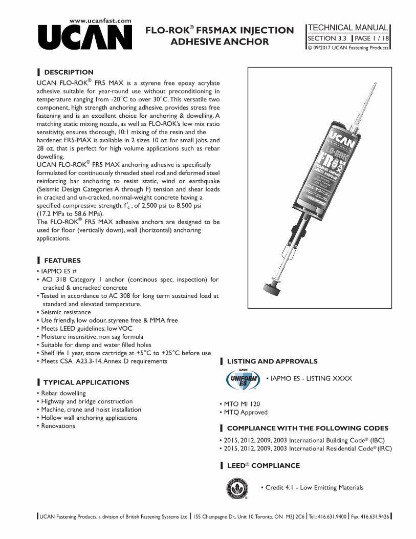
l DESCRIPTIONUCAN FLO-ROK® FR5 MAX is a styrene free epoxy acrylateadhesive suitable for year-round use without preconditioning intemperature ranging from -20°C to over 30°C. This versatile twocomponent, high strength anchoring adhesive, provides stress freefastening and is an excellent choice for anchoring & dowelling. Amatching static mixing nozzle, as well as FLO-ROK’s low mix ratiosensitivity, ensures thorough, 10:1 mixing of the resin and the hardener. FR5-MAX is available in 2 sizes 10 oz. for small jobs, and28 oz. that is perfect for high volume applications such as rebardowelling. UCAN FLO-ROK® FR5 MAX anchoring adhesive is specificallyformulated for continuously threaded steel rod and deformed steelreinforcing bar anchoring to resist static, wind or earthquake(Seismic Design Categories A through F) tension and shear loadsin cracked and un-cracked, normal-weight concrete having a specified compressive strength, f ’c , of 2,500 psi to 8,500 psi (17.2 MPa to 58.6 MPa). The FLO-ROK® FR5 MAX adhesive anchors are designed to beused for floor (vertically down), wall (horizontal) anchoring applications.
www.ucanfast.comFLO-ROK® FR5MAX INJECTION
ADHESIVE ANCHORTECHNICAL MANUALSECTION 3.3 PAGE 1 / 18© 09/2017 UCAN Fastening Products
UCAN Fastening Products, a division of British Fastening Systems Ltd. 155 Champagne Dr., Unit 10, Toronto, ON M3J 2C6 Tel.: 416.631.9400 Fax: 416.631.9426
l TYPICAL APPLICATIONS• Rebar dowelling• Highway and bridge construction• Machine, crane and hoist installation• Hollow wall anchoring applications• Renovations
l FEATURES• IAPMO ES #• ACI 318 Category 1 anchor (continous spec. inspection) for
cracked & uncracked concrete• Tested in accordance to AC 308 for long term sustained load at
standard and elevated temperature.• Seismic resistance• Use friendly, low odour, styrene free & MMA free • Meets LEED guidelines; low VOC• Moisture insensitive, non sag formula• Suitable for damp and water filled holes• Shelf life 1 year, store cartridge at +5°C to +25°C before use• Meets CSA A23.3-14, Annex D requirements l LISTING AND APPROVALS
• MTO MI 120• MTQ Approved
• IAPMO ES - LISTING XXXX
l LEED® COMPLIANCE
™NSF® • Credit 4.1 - Low Emitting Materials
l COMPLIANCE WITH THE FOLLOWING CODES
• 2015, 2012, 2009, 2003 International Building Code® (IBC)• 2015, 2012, 2009, 2003 International Residential Code® (IRC)

www.ucanfast.com
FLO-ROK® FR5MAX INJECTIONADHESIVE ANCHOR
TECHNICAL MANUALSECTION 3.3 PAGE 2 / 18© 09/2017 UCAN Fastening Products
UCAN Fastening Products, a division of British Fastening Systems Ltd. 155 Champagne Dr., Unit 10, Toronto, ON M3J 2C6 Tel.: 416.631.9400 Fax: 416.631.9426
Standard Threaded Rod / Carbon Steel
High Strength Threaded Rod / Carbon
Steel
Stainless Steel Threaded Rod
Carbon Steel Nuts
Stainless Steel Nuts
Carbon and Stainless Steel Washers
l MATERIAL SPECIFICATIONS
fu
fy
fu
fy
fu
fy
---
psi 72,500MPa 500psi 58,000
MPa 400psi 125,000
MPa 862psi 105,000
MPa 724psi 100,000
MPa 689psi 65,000
MPa 448
- -- -
- -
ISO 898 Grade 5.8
ASTM A 193, Grade B7
ASTM F 593 (AISI 304/316)
ASTM A 563
ASTM F 594
ASTM B18.22.1 Type A Plain
TABLE 1. ANCHOR RODS
Properties Symbol Unit Value Test Standard
TABLE 2 - CURED EPOXY
Compressive Strength
Tensile Strength
Elongation at Break
Tensile Modulus
Flexural Strength
HDT (Heat Deflection Temp.)
24 hrs.
7 days
24 hrs
7 days
24 hrs.7 days
24 hrs.
7 days
24 hrs
7 days
psi 10,400MPa 72psi 11,100
MPa 77psi 1,885
MPa 13psi 2,175
MPa 15
%6.07.0
psi 536,000GNm-2 3.7psi 551,000
GNm-2 3.7psi 4,200
MPa 29°F 169
°C 76
ASTM D 695 @ 20°C/72°
ASTM D 638 @ 20°C/72°
ASTM D 638 @ 20°C/72°
ASTM D 638 @ 20°C/72°
ASTM D 790 @ 20°C/72°
ASTM D 648 @ 20°C/72°
Properties Unit Value Test Standard

l TABLE 3. CURING TIMES
www.ucanfast.comFLO-ROK® FR5MAX INJECTION
ADHESIVE ANCHORTECHNICAL MANUALSECTION 3.3 PAGE 3 / 18© 09/2017 UCAN Fastening Products
UCAN Fastening Products, a division of British Fastening Systems Ltd. 155 Champagne Dr., Unit 10, Toronto, ON M3J 2C6 Tel.: 416.631.9400 Fax: 416.631.9426
Temperature Gel Time Full Cure
-20°C to -10°C -4°F to 14°F 16 minutes 48 hours-10°C to 0°C 14°F to 32°F 16 minutes 48 hours
0°C to + 5°C 41°F to 50°F 10 minutes 145 minutes+5°C to +10°C 50°F to 59°F 8 minutes 85 minutes+10°C to +15°C 59°F to 68°F 6 minutes 75 minutes+15°C to +20°C 68°F to 77°F 5 minutes 50 minutes+20°C to +25°C 77°F to 86°F 4 minutes 40 minutes+25°C to +30°C 86°F to 95°F 2 minutes 30 minutes
Do not disturb stud during the curing time*Cartridge temperature +5ºC (41ºF)
Tinst
dhole
tfix
do
hef
hmin
l IN SERVICE TEMPERATURE RANGE
Short Term : -40°C (-40°F) to +80°C (+176° F) Long Term : -40°C (-40°F) to +50° (+122° F

www.ucanfast.com
FLO-ROK® FR5MAX INJECTIONADHESIVE ANCHOR
TECHNICAL MANUALSECTION 3.3 PAGE 4 / 18© 09/2017 UCAN Fastening Products
UCAN Fastening Products, a division of British Fastening Systems Ltd. 155 Champagne Dr., Unit 10, Toronto, ON M3J 2C6 Tel.: 416.631.9400 Fax: 416.631.9426
HOLLOW CONCRETE BLOCK/MASONRY APPLICATIONS
NOTE:• Clean hole thoroughly by using nylon brush and blow-out bulb or compressed air (65 - 80 psi)• Always dispense about 1 oz. FLO - ROK to the side, prior to injecting it into the clean hole, to assure uniform mixing indicated by a consistent
dark grey colour.• At a minimum, half fill the hole starting from the bottom up by slowly withdrawing the nozzle. (solid installation)
Fill the screen fully starting from the bottom by slowly withdrawing the nozzle. (hollow installation)• Mark embedment depth on the threaded rod (rebar) prior to installation, and insert the rod (rebar) turning it slowly until it reaches the
bottom of the hole ( depth mark is flush with the surface). • Observe curing time. The installed anchor must not be disturbed or loaded before the specified curing time has elapsed.
SOLID CONCRETE/MASONRY APPLICATIONS
TABLE 4 - ANCHOR SYSTEM INSTALLATION INFORMATION
UNC Threaded Bar
US Re-bar
Metric Threaded Rod
MetricRe-bar (CAN)
Characteristics Symbol Unit Nominal Anchor Element Diameter
l INSTALLATION
For SI: 1 inch = 25.4 mm, 1ft.lb = 1.356 N.m
Maximum Tightening Torque
Embedment Depth Range
Minimum Concrete Thickness
Critical Edge Distance
Minimum Edge Distance
Minimum Anchor Spacing
Size
Drill Size
Size
Drill Size
Size
Drill Size
Size
Drill Size
do inch 3/8 1/2 5/8 3/4 7/8 1 1-1/4
dhole inch 1/2 9/16 3/4 7/8 1 1-1/8 1-3/8
do inch #3 #4 #5 #6 #7 #8 #10
dhole inch 9/16 5/8 3/4 7/8 1 1-1/8 1-3/8
do mm M10 M12 M16 M20 - M24 M30
dhole mm 1 14 18 22 - 26 35
M - 10M - 15M 20M - 25M 30M
dhole inch 9/16 - 3/4 7/8 - 1-1/4 1-1/2
Tinst ft.lb 15 30 60 100 125 150 200
hef,min inch 2-3/8 2-3/4 3-1/8 3-3/4 4 4 5
hef,max inch 7-1/2 10 12-1/2 15 17-1/2 20 25
hmin inch 2.0 . hef
Cac inch See Section 3.1.10. (IAPMO ES Report # xxxx)
Cmin inch 0.5 . hef
Smin inch 0.5 . hef
2x 2x

www.ucanfast.comFLO-ROK® FR5MAX INJECTION
ADHESIVE ANCHORTECHNICAL MANUALSECTION 3.3 PAGE 5 / 18© 09/2017 UCAN Fastening Products
UCAN Fastening Products, a division of British Fastening Systems Ltd. 155 Champagne Dr., Unit 10, Toronto, ON M3J 2C6 Tel.: 416.631.9400 Fax: 416.631.9426
l STRENGTH DESIGN
General: The design strength of anchors shall be determined in accordance with ACI 318-14 chapter 17 or ACI 318-11 Appendix Dand the IAPMO ES # xxxxreport.
The strength design of anchors must comply with ACI 318-14 and Section 3.2.2 of IAPMO ES # xxxx report.
Design parameters, including strength reduction factors, φ, corresponding to each limit state, are provided in Tables 6 through 12.Strength reduction factors, Ф Applies when load combinations of Section 1605.2 of the IBC or ACI 318-14 Section 5.3 (ACI 318-11 Section 9.2), are used in accordance with ACI 318-14 Section 17.3.3 (ACI 318-11 Section D.4.3). If the load combina-tions of ACI 318 Appendix C are used, the appropriate value of Ф shall be determined in accordance with ACI 318 D.4.4.
Interaction of Tensile and Shear Forces: For designs that include combined tension and shear forces, the interaction of the tension and shear loads must be calculated in accordance with ACI 318-14 Section 17.5.3.1 (ACI 318-11 Section D.4.3)
l LIMIT STATE DESIGN (CSA A23.3-14, ANNEX D)
The design strength of anchors in Limit State Design (Canada) shall comply with CSA A23.3-14, Annex D. Design parameters are provided in Tables 6 through 12. Strength Reduction Factors (R) and Material Resistance Factors (Ф) areprovided in Table 5. The requirements for member thickness edge distance and spacing shown in Table must apply. For designsthat include tension and shear forces, the interaction of the loads must be calculated in accordance with CSA A23.3-14, Annex D.8
Nominal Anchor Diameter (in.)
Characteristic Symbol Units 3/8” 1/2” 5/8” 3/4” 7/8” 1” 1-1/4”
10M 15M 20M 25M 30M
Concrete material resistance factor (dry concrete) Фc - 0.65
Steel material resistance factor Фs - 0.85 Strength reduction factor for tension, steel failure R 0.80modes (carbon and stainless steel threaded rod)Strength reduction factor for tension, steel failure R 0.70modes (reinforcing bar)Strength reduction factor for shear, steel failure modes R 0.75(carbon and stainless steel threaded rod)Strength reduction factor for shear, steel failure modes R 0.65(reinforcing bar)Strength reduction factor for tension, concrete R
Cond. A 1.15failure modes Cond. B 1.00Strength reduction factor for Shear, concrete R Cond. A 1.15failure modes Cond. B 1.00Coefficient for factored concrete breakout in k - 7tension, cracked concreteModification factor concrete resistance to account Ψc,N - 1.4uncracked concrete
TABLE 5 - RESISTANCE FACTORS FOR LIMIT STATE DESIGN IN ACCORDANCE WITH CSA A23.3-14, ANNEX D

www.ucanfast.com
FLO-ROK® FR5MAX INJECTIONADHESIVE ANCHOR
TECHNICAL MANUALSECTION 3.3 PAGE 6 / 18© 09/2017 UCAN Fastening Products
UCAN Fastening Products, a division of British Fastening Systems Ltd. 155 Champagne Dr., Unit 10, Toronto, ON M3J 2C6 Tel.: 416.631.9400 Fax: 416.631.9426
For SI: 1 inch = 25.4 mm, 1 in.2 = 645.16 mm2, 1 lb = 0.004448 kN1Values provided for common rod material types are based on specified strength and calculated in accordance with ACI 318-14 Eq. (17.4.1.2) and Eq. (17.5.1.2b) or ACI 318-11 Eq. (D-2) and Eq. (D-29). Nuts and washers shall be appropriate for the rod as set forth in Table 1 of this report.
2Stress area is minimum stress area applicable for either tension or shear.3Tabulate value of φ complies with ACI 318-14 Section 17.3.3 (ACI 318-11 Section D.4.3) and applies when the load combinations of Section 1605.1 of theIBC or ACI318-14 Section 5.3 (ACI 318-11 Section 9.2) are used. When the load combinations in ACI 318 Appendix C are used, the appropriate value of φshall be determined in accordance with ACI 318-11 D.4.4.
4For limit state design as per CSA A23.3-14, Annex D, Material resistance factors (ɸ) and resistance modification factors (R) in table shall be used.
TABLE 6—STEEL DESIGN INFORMATION FOR FRACTIONAL CARBON STEEL AND STAINLESS STEEL THREADEDROD1,2,3,4
Characteristic Symbol Units Nominal Rod Diameter, do
Nominal Size do inch 3/8 1/2 5/8 3/4 7/8 1 1-1/4
Stress Area1 Ase in.2 0.0775 0.1419 0.226 0.334 0.462 0.606 0.969
Reduction Factor for Tension SteelFailure3,4 Ø - 0.75
Strength Reduction Factor for Shear Steel Failure3,4 Ø - 0.65
Tension Resistance of Carbon SteelNsa
lb 5,620 10,290 16,385 24,250 33.475 43,910 70,260ISO 898-1 Class 5.8 (kN) (25.0) (45.8) (72.9) (107.9) (148.9) (195.3) (312.5)
Tension Resistance of Carbon SteelNsa
lb 9,690 17,740 28,250 41,750 57,750 75,750 121,125ASTM A193 B7 (kN) (43.1) (78.9) (125.7) (185.7) (256.9) (337.0) (538.8)
Shear Resistance of Carbon SteelVsa
lb 2,810 6,175 9,830 14,550 20,085 26,345 42,155ISO 898-1 Class 5.8 (kN) (12.5) (27.5) (43.7) (64.7) (89.3) (117.2) (187.5)
Shear Resistance of Carbon SteelVsa
lb 4,845 10,645 16,950 25,050 34,650 45,450 72,675ASTM A193 B7 (kN) (21.6) (47.4) (75.4) (111.4) (154.1) (202.2) (323.3)
Strength Reduction Factor for TensionSteel Failure3,4 Ø - 0.75
Strength Reduction Factor for ShearSteel Failure3,4 Ø - 0.65
Tension Resistance of Stainless SteelNsa
lb 7,750 14,190 22,600 -- -- -- --ASTM F593 CW1 (kN) (34.5) (63.1) (100.5)
Tension Resistance of Stainless SteelNsa
lb -- -- -- 28,390 39,270 51,510 82,365ASTM F593 CW2 (kN) (126.3) (174.7) (229.1) (366.4)
Tension Resistance of Stainless SteelNsa
lb 8,915 16,320 25,990 -- -- -- --ASTM F593 SH1 (kN) (39.7) (72.6) (115.6)
Tension Resistance of Stainless Steel Nsa lb -- -- -- 35,070 48,510 63,630 --ASTM F593 SH2 (kN) (156.0) (215.8) (283.0
Tension Resistance of Stainless SteelNsa
lb -- -- -- -- -- -- 92,055ASTM F593 SH3 (kN) (409.5)
Shear Resistance of Stainless SteelVsa
lb 3,875 7,095 11,300 -- -- -- --ASTM F593 CW1 (kN) (17.2) (31.6) (50.3)Shear Resistance of Stainless Steel
Vsalb -- -- -- 14,195 19,635 25,755 41,185
ASTM F593 CW2 (kN) (63.1) (87.3) (114.6) (183.2)
Shear Resistance of Stainless SteelVsa
lb 4,455 9,790 15,595 -- -- -- --ASTM F593 SH1 (kN) (19.8) (43.5) (69.4)
Shear Resistance of Stainless SteelVsa
lb -- -- -- 17,535 24,255 31,815 --ASTM F593 SH2 (kN) (78.0) (107.9) (141.5)
Shear Resistance of Stainless Steel Vsa lb -- -- -- -- -- -- 46,030ASTM F593 SH3 (kN) (204.8)
Car
bon
Stee
l Thr
eade
d R
odSt
ainl
ess
Stee
l Thr
eade
d R
od

www.ucanfast.comFLO-ROK® FR5MAX INJECTION
ADHESIVE ANCHORTECHNICAL MANUALSECTION 3.3 PAGE 7 / 18© 09/2017 UCAN Fastening Products
UCAN Fastening Products, a division of British Fastening Systems Ltd. 155 Champagne Dr., Unit 10, Toronto, ON M3J 2C6 Tel.: 416.631.9400 Fax: 416.631.9426
TABLE 7a—STEEL DESIGN INFORMATION FOR FRACTIONAL STEEL US REINFORCING BAR1,2,3
Characteristic Symbol UnitsNominal Reinforcing Bar size, do
No. 3 No. 4 No. 5 No. 6 No. 7 No. 8 No. 10
Nominal bar diameter do inch 0.375 0.500 0.625 0.750 0.875 1.000 1.250
Stress Area Ase in.2 0.11 0.20 0.31 0.44 0.60 0.79 1.27
Strength Reduction Factor Ø 0.75for Tension Steel Failure
Strength Reduction Shear Ø 0.65for Tension Steel FailureTension Resistance of Carbon Steel Nsa
lb 6,600 12,000 18,600 26,400 36,000 47,400 76,200
ASTM A615 Grade 40 (kN) (29.4) (53.4) (82.7) (117.4) (160.1) (210.8) (339.0)
Tension Resistance of Carbon Steel Nsalb 9,900 18,000 27,900 39,600 54,000 71,100 114,300
ASTM A615 Grade 60 (kN) (44.0) (80.1) (124.1) (176.1) (240.2) (316.3) (508.4)
Tension Resistance of Carbon Steel Vsalb 3,960 7,200 11,160 15,840 21,600 28,440 45,720
ASTM A615 Grade 40 (kN) (17.6) (32.0) (49.6) (70.5) (96.1) (126.5) (203.4)
Tension Resistance of Carbon Steel Vsalb 5,940 10,800 16,740 23,760 32,400 42,660 68,580
ASTM A615 Grade 60 (kN) (26.4) (48.0) (74.5) (105.7) (144.1) (189.8) (305.1)
Rei
nfor
cing
bar
For SI: 1 inch = 25.4 mm, 1 in.2 = 645.16 mm2, 1 lb = 0.004448 kN
TABLE 7b—STEEL DESIGN STRENGTH FOR CAN GRADE 400 REINFORCING BAR1,2
1Values provided for common rod material types are based on specified strength and calculated in accordance with ACI 318-14 Eq. (17.4.1.2) and Eq. (17.5.1.2b) or ACI 318-11 Eq. (D-2) and Eq. (D-29). Nuts and washers shall be appropriate for the rod as set forth in Table 3 of this report.
2Stress area is minimum stress area applicable for either tension or shear.3Tabulate value of φ complies with ACI 318-14 Section 17.3.3 (ACI 318-11 Section D.4.3) and applies when the load combinations of Section 1605.1 of theIBC or ACI318-14 Section 5.3 (ACI 318-11 Section 9.2) are used. When the load combinations in ACI 318 Appendix C are used, the appropriate value of φshall be determined in accordance with ACI 318-11 D.4.4.
Rebar size Area(mm2) futa(MPa) fya(MPa) Tension Nsar Shear Vsar Seismic Shear Vsar
36.72 kN 17.44 kN 12.73 kN10M 100 540 400 8,255 lb 3,921 lb 2,863 lb
73.44 kN 34.88 kN 23.37 kN15M 200 540 400 16,511 lb 7,843 lb 5,255 lb
110.16 kN 52.33 kN 35.06 kN20M 300 540 40024,766 lb 11,764 lb 7,882 lb
183.60 kN 87.21 kN 53.20 kN25M 500 540 400 41,277 lb 19,607 lb 11,960 lb
257.04 kN 122.09 kN 56.16 kN30M 700 540 400 57,788 lb 27,449 lb 12,627 lb
1Tabulated value are calculated in accordance with CSA A23.3-14 Annex D (Factored Resistance Loads)2CSA G30.18 Grade 400 reinforcing bar are considered ductile steel elements.

www.ucanfast.com
FLO-ROK® FR5MAX INJECTIONADHESIVE ANCHOR
TECHNICAL MANUALSECTION 3.3 PAGE 8 / 18© 09/2017 UCAN Fastening Products
UCAN Fastening Products, a division of British Fastening Systems Ltd. 155 Champagne Dr., Unit 10, Toronto, ON M3J 2C6 Tel.: 416.631.9400 Fax: 416.631.9426
Characteristic Symbol UnitsBar size
10M 15 M 20M 25M 30M
Embedment Depth Rangehef,min inch 2-3/8 3-1/8 3-1/2 4 5hef,max inch 7-1/2 12-1/2 15 20 25
Minimum Anchor Spacing smin inch 0.5 · hef
Minimum Edge Distance cmin inch 0.5 · hef
Minimum Concrete Thickness hmin inch 2.0 · hef
Critical Edge Distance cac- See Section 3.1.10 (IAPMO ES Report # xxxx)
Effectiveness Factor for Uncracked kc,uncr-- 24
Concrete, Breakout (SI) (10)
Effectiveness Factor for Cracked Concrete, kc,cr-- 17
Breakout (SI) (7.1)kc,uncr / kc,cr -- -- 1.41
Strength Reduction Factor for Tension, Ø -- 0.65Concrete Failure Modes, Condition B3
Strength Reduction Factor for Shear, Ø -- 0.70Concrete Failure Modes, Condition B3
TABLE 9—CANADIAN METRIC REINFORCING BAR CONCRETE BREAKOUT STRENGTH DESIGN INFORMATION1,2,3
For SI: 1 inch = 25.4 mm, 1 in.2 = 645.16 mm2, 1 lb = 0.004448 kN
1The tabulated value of ɸ applies when the load combinations of Section 1605.2 of the IBC, or ACI 318-14 Section 5.3(ACI 318 Section 9.2), are used in accor-dance with ACI 318-14 Section 17.3.3 (ACI 318-11 Section D.4.3). If the load combinations of ACI 318 Appendix C are used, the appropriate value of ɸ shall bedetermined in accordance with ACI 318 D.4.4.2The values of ɸ correspond to Condition B as described in Section 17.3.3 of ACI 318-14 (Section D.4.3 of ACI 318-11) for post-installation anchors designedusing the load combination of IBC Section 1605.2. If the load combinations of ACI 318-11 Appendix C are used, the corresponding value of ɸ shall be determined.3For limit state design as per CSA A23.3-14, Annex D, material resistance factors (ɸ) and resistance modification factors (R) in table shall be used. Condition Bapplies where supplemental reinforcement is not provided as per CAS A23.3-14, Clause D.5.3
Characteristic Symbol Units Nominal Anchor Element Diameter
US Threaded RodSize do inch 3/8 1/2 5/8 3/4 7/8 1 1-1/4
Drill Size dhole inch 1/2 9/16 3/4 7/8 1 1-1/8 1-3/8
US Re-barSize do inch No. 3 No. 4 No. 5 No. 6 No. 7 No. 8 No. 10
Drill Size dhole inch 9/16 5/8 3/4 1 1 1-1/4 1-5/8
Embedment Depth Rangehef,min inch 2-3/8 2-3/4 3-1/8 3-1/2 4 4 5hef,max inch 7-1/2 10 12-1/2 15 17-1/2 20 25
Minimum Anchor Spacing smin inch 0.5 · hef
Minimum Edge Distance cmin inch 0.5 · hef
Minimum Concrete Thickness hmin inch 2.0 · hef
Critical Edge Distance cac - See ACI 318 D.8.6
Effectiveness Factor for Uncracked kc,uncr-- 24
Concrete, Breakout (SI) (10)
Effectiveness Factor for Cracked Concrete, kc,cr-- 17
Breakout (SI) (7.1)kc,uncr / kc,cr -- -- 1.41
Strength Reduction Factor for Tension, Ø -- 0.65Concrete Failure Modes, Condition B2
Strength Reduction Factor for Shear, Ø -- 0.70Concrete Failure Modes, Condition B2
TABLE 8 - FRACTIONAL THREADED ROD AND REINFORCING BAR CONCRETE BREAKOUT STRENGTH DESIGN INFORMATION1,2

www.ucanfast.comFLO-ROK® FR5MAX INJECTION
ADHESIVE ANCHORTECHNICAL MANUALSECTION 3.3 PAGE 9 / 18© 09/2017 UCAN Fastening Products
UCAN Fastening Products, a division of British Fastening Systems Ltd. 155 Champagne Dr., Unit 10, Toronto, ON M3J 2C6 Tel.: 416.631.9400 Fax: 416.631.9426
TABLE 10 - BOND STRENGTH DESIGN INFORMATION FOR FRACTIONAL STEEL THREADED RODS IN HAMMERDRILLED HOLES1,2,3,4,5,6
Nominal Anchor Element DiameterDesign Information Symbol Units 3/8” 1/2” 5/8” 3/4” 1” 1-1/4”
Minimun Embedment Depth hef,min inch 2-3/8 2-3/4 3-1/4 3-1/2 4 5
Maximun Embedment Depth hef,max inch 7-1/2 10 12-1/2 15 20 25Characteristic Bond Strength in psi 1,320 1,237 1,154 1,070Uncracked Concrete for Sustained tk,sust,uncr - -Tension loading2,3 (N/mm2) (9.10) (8.53) (7.95) (7.38)
Characteristic Bond Strength in psi 1,230 1,237 1,154 1,070 Uncracked Concrete for Short Term tk,uncr
(N/mm2) (9.10) (8.53) (7.95) (7.38) - -Loads2,3
Characteristic Bond Strength in Cracked tk,sust,crpsi 598 817 769 720 623 518
Concrete for Sustained Tension Loading2,3 (N/mm2) (4.13) (5.63) (5.30) (4.96) (4.29) (3.57) Characteristic Bond Strength in Cracked tk,cr psi 598 817 769 720 623 518Concrete for Short Term Loads2,3 (N/mm2) (4.13) (5.63) (5.30) (4.96) (4.29) (3.57)
Anchor- 2 2 2 2 2 3
Dry Concrete Category Ød - 0.55 0.55 0.55 0.55 0.55 0.45
Water-saturatedAnchor - 1 2 2 2 2 3Catergory
Concrete Øws - 0.65 0.55 0.55 0.55 0.55 0.55
Water-filled HolesAnchor - 3 3 3 3 3 3CategoryØwf - 0.45 0.45 0.45 0.45 0.45 0.45Anchor
- 1 1 1 1 1 1Dry Concrete Category
Ød - 0.65 0.65 0.65 0.65 0.65 0.65
Water-saturatedAnchor - 1 1 1 1 1 3Catergory
Concrete Øws - 0.65 0.65 0.65 0.65 0.65 0.65
Water-filled HolesAnchor - 1 1 1 1 1 1CategoryØwf - 0.65 0.65 0.65 0.65 0.65 0.65
Reduction for Seismic Tension αN,seis - 1.00 0.41 0.54 1.00 0.50 0.96
For SI: 1 inch = 25.4 mm, 1 in.2 = 645.16 mm2, 1 lb = 0.004448 kN
IBond strength values correspond to concrete compressive strength, f ’c = 2,500 psi
2Maximum long term temperature: 122°F (+50°C); maximum short term temperature: 176°F (+80°C)3Short term elevated concrete temperatures are those that occur over brief intervals, e.g. transient or part of a regular cycle of heating andcooling, such as day-night temperature rise and fall. Long term elevated concrete temperatures are roughly constant over significant periods oftime.4The tabulated value of ɸ applies when load combinations of Section 1605.2 of the IBC or ACI 318-14 Section 5.3 (ACI 318-11 Section 9.2),are used in accordance with ACI 318-14 Section 17.3.3 (ACI 318-11 Section D.4.3). If the load combinations of ACI 318 Appendix C are used,the appropriate value of ɸ shall be determined in accordance with ACI 318 D.4.4. 5The value of ɸ correspond to Condition B as described in Section 17.3.3 of ACI 318-14 (Section D.4.3 of ACI 318-11) for post-installedanchors designed using the load combinations of IBC Section 1605.2. If the load combinations in ACI 318-11 Appendix C are used, the corre-sponding value ɸ shall be determined.6For limit state design as per CSA A23.3-14, Annex D, material resistance factors (ɸ) and resistance modification factors (R) in table shall beused. Condition B applies where supplemental reinforcement is not provided as per CAS A23.3-14, Clause D.5.3
PermissibleInstallationConditions,Periodic SpecialInspection
PermissibleInstallationConditions,Continuous SpecialInspection

UCAN Fastening Products, a division of British Fastening Systems Ltd. 155 Champagne Dr., Unit 10, Toronto, ON M3J 2C6 Tel.: 416.631.9400 Fax: 416.631.9426
www.ucanfast.com
FLO-ROK® FR5MAX INJECTIONADHESIVE ANCHOR
TECHNICAL MANUALSECTION 3.3 PAGE 10/18© 09/2017 UCAN Fastening Products
TABLE 11 - BOND STRENGTH DESIGN INFORMATION FOR US REINFORCING BARS IN HAMMER DRILLED HOLESUSED AS ANCHOR ELEMENTS1,2,3,4,5
Nominal Anchor Element DiameterDesign Information Symbol Units #3 #4 #5 #6
Minimum Embedment Depth hef,min inch 2-3/8 2-3/4 3-1/4 3-1/2
Maximun Embedment Depth hef,max inch 7-1/2 10 12-1/2 15Characteristic Bond Strength in psi 1,262 1,174 1,087 1,000Uncracked Concrete for Sustained tk,sust,uncr Tension loading2,3 (N/mm2) (8.70) (8.10) (7.49) (6.89)
Characteristic Bond Strength in psi 1,262 1,174 1,087 1,000 Uncracked Concrete for Short Term tk,uncr
(N/mm2) (8.70) (8.10) (7.49) (6.89)Loads2,3Anchor - 2 2 2 2
Dry Concrete Category Ød - 0.55 0.55 0.55 0.55
Water-saturatedAnchor
- 1 2 2 2 CatergoryConcrete Øws - 0.65 0.55 0.55 0.55
Water-filled HolesAnchor - 3 3 3 3 CategoryØwf - 0.45 0.45 0.45 0.45Anchor - 1 1 1 1
Dry Concrete Category Ød - 0.65 0.65 0.65 0.65
Water-saturated Anchor - 1 1 1 1 CatergoryConcreteØws - 0.65 0.65 0.65 0.65
Water-filled Holes Anchor - 1 1 1 1 Category Øwf - 0.65 0.65 0.65 0.65
PermissibleInstallationConditions,Periodic SpecialInspection
PermissibleInstallationConditions,Continuous SpecialInspection
For SI: 1 inch = 25.4 mm, 1 in.2 = 645.16 mm2, 1 lb = 0.004448 kN
IBond strength values correspond to concrete compressive strengths ranging from 2,500 psi to 8,000 psi.
2Maximum long term temperature: 122°F (+50°C); maximum short term temperature: 176°F (+80°C)3Short term elevated concrete temperatures are those that occur over brief intervals, e.g. transient or part of a regular cycle of heating andcooling, such as day-night temperature rise and fall. Long term elevated concrete temperatures are roughly constant over significant periods oftime.4The tabulated value of ɸ applies when load combinations of Section 1605.2 of the IBC or ACI 318-14 Section 5.3 (ACI 318-11 Section 9.2),are used in accordance with ACI 318-14 Section 17.3.3 (ACI 318-11 Section D.4.3). If the load combinations of ACI 318-11 Appendix C areused, the appropriate value of ɸ shall be determined in accordance with ACI 318 D.4.4. 5The value of ɸ correspond to Condition B as described in Section 17.3.3 of ACI 318-14 (Section D.4.3 of ACI 318-11) for post-installedanchors designed using the load combinations of IBC Section 1605.2. If the load combinations in ACI 318-11 Appendix C are used, the corre-sponding value ɸ shall be determined.
UCAN Fastening Products, a division of British Fastening Systems Ltd. 155 Champagne Dr., Unit 10, Toronto, ON M3J 2C6 Tel.: 416.631.9400 Fax: 416.631.9426
www.ucanfast.comFLO-ROK® FR5MAX INJECTION
ADHESIVE ANCHORTECHNICAL MANUALSECTION 3.3 PAGE 11/18© 09/2017 UCAN Fastening Products
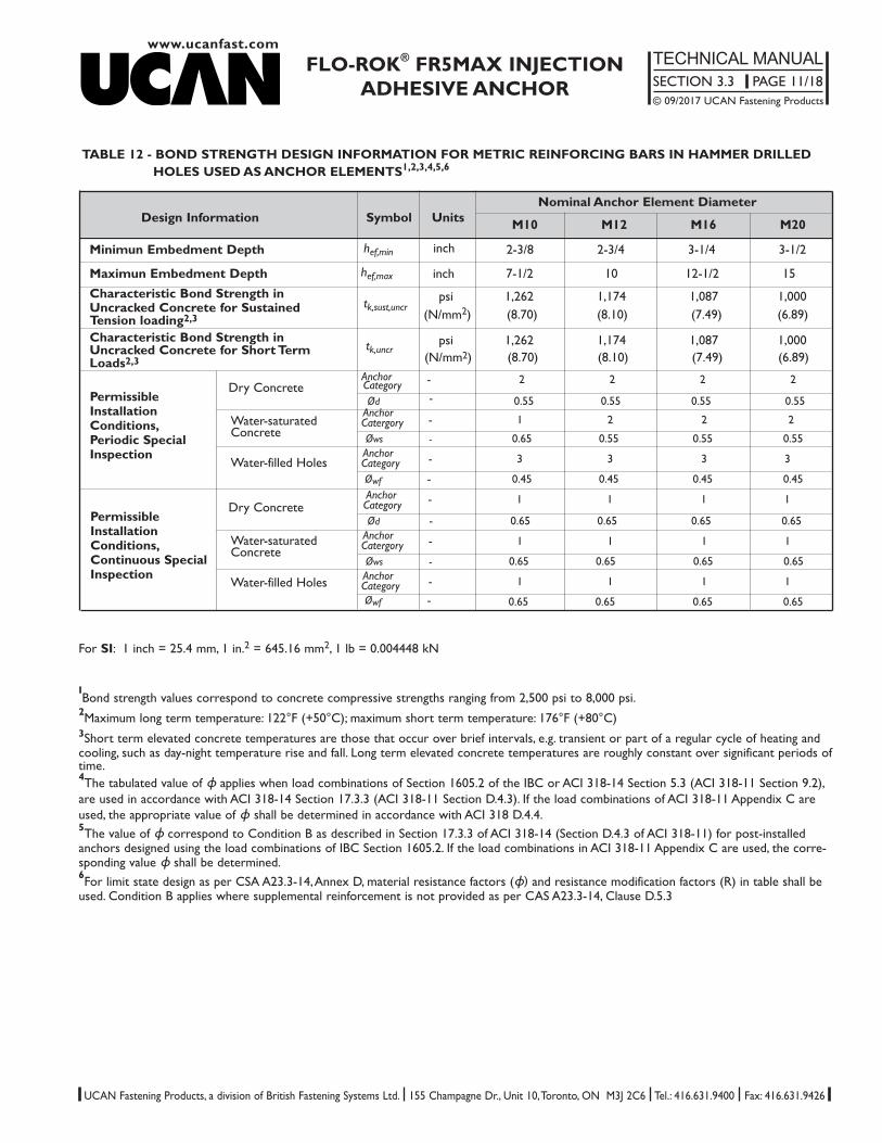
TABLE 12 - BOND STRENGTH DESIGN INFORMATION FOR METRIC REINFORCING BARS IN HAMMER DRILLED HOLES USED AS ANCHOR ELEMENTS1,2,3,4,5,6
Nominal Anchor Element DiameterDesign Information Symbol Units M10 M12 M16 M20
Minimun Embedment Depth hef,min inch 2-3/8 2-3/4 3-1/4 3-1/2
Maximun Embedment Depth hef,max inch 7-1/2 10 12-1/2 15Characteristic Bond Strength in psi 1,262 1,174 1,087 1,000Uncracked Concrete for Sustained tk,sust,uncr Tension loading2,3 (N/mm2) (8.70) (8.10) (7.49) (6.89)
Characteristic Bond Strength in psi 1,262 1,174 1,087 1,000 Uncracked Concrete for Short Term tk,uncr
(N/mm2) (8.70) (8.10) (7.49) (6.89)Loads2,3Anchor - 2 2 2 2
Dry Concrete Category Ød - 0.55 0.55 0.55 0.55
Water-saturatedAnchor
- 1 2 2 2 CatergoryConcrete Øws - 0.65 0.55 0.55 0.55
Water-filled HolesAnchor - 3 3 3 3 CategoryØwf - 0.45 0.45 0.45 0.45Anchor - 1 1 1 1
Dry Concrete Category Ød - 0.65 0.65 0.65 0.65
Water-saturated Anchor - 1 1 1 1 CatergoryConcreteØws - 0.65 0.65 0.65 0.65
Water-filled Holes Anchor - 1 1 1 1 Category Øwf - 0.65 0.65 0.65 0.65
PermissibleInstallationConditions,Periodic SpecialInspection
PermissibleInstallationConditions,Continuous SpecialInspection
For SI: 1 inch = 25.4 mm, 1 in.2 = 645.16 mm2, 1 lb = 0.004448 kN
IBond strength values correspond to concrete compressive strengths ranging from 2,500 psi to 8,000 psi.
2Maximum long term temperature: 122°F (+50°C); maximum short term temperature: 176°F (+80°C)3Short term elevated concrete temperatures are those that occur over brief intervals, e.g. transient or part of a regular cycle of heating andcooling, such as day-night temperature rise and fall. Long term elevated concrete temperatures are roughly constant over significant periods oftime.4The tabulated value of ɸ applies when load combinations of Section 1605.2 of the IBC or ACI 318-14 Section 5.3 (ACI 318-11 Section 9.2),are used in accordance with ACI 318-14 Section 17.3.3 (ACI 318-11 Section D.4.3). If the load combinations of ACI 318-11 Appendix C areused, the appropriate value of ɸ shall be determined in accordance with ACI 318 D.4.4. 5The value of ɸ correspond to Condition B as described in Section 17.3.3 of ACI 318-14 (Section D.4.3 of ACI 318-11) for post-installedanchors designed using the load combinations of IBC Section 1605.2. If the load combinations in ACI 318-11 Appendix C are used, the corre-sponding value ɸ shall be determined.6For limit state design as per CSA A23.3-14, Annex D, material resistance factors (ɸ) and resistance modification factors (R) in table shall beused. Condition B applies where supplemental reinforcement is not provided as per CAS A23.3-14, Clause D.5.3
www.ucanfast.com
FLO-ROK® FR5MAX INJECTIONADHESIVE ANCHOR
TECHNICAL MANUALSECTION 3.3 PAGE 12/18© 09/2017 UCAN Fastening Products
UCAN Fastening Products, a division of British Fastening Systems Ltd. 155 Champagne Dr., Unit 10, Toronto, ON M3J 2C6 Tel.: 416.631.9400 Fax: 416.631.9426
Sustained Tension Design Strength - ɸNn Shear Design Strength - ɸVnAnchor Size Embedment
Depth 3,000 psi 4,000 psi 6,000 psi 3,000 psi 4,000 psi 6,000 psi (20.7 MPa) (27.8 MPa) (41.4 MPa) (20.7 MPa) (27.8 MPa) (41.4 MPa)
60 mm 10.62 kN 10.62 kN 10.62 kN 17.49 kN 20.27 kN 24.73 kN2-3/8 inch 2,388 lb 2,388 lb 2,388 lb 3,932 lb 4,557 lb 5,561 lb
86 mm 15.22 kN 15.22 kN 15.22 kN 32.25 kN 37.78 kN 45.61 kN3/8” 3-3/8 inch 3,422 lb 3,422 lb 3,422 lb 7,251 lb 8,403 lb 10,255 lb
191 mm 33.81 kN 33.81 kN 33.81 kN 125.22 kN 145.12 kN 177.09 kN7-1/2 inch 7,600 lb 7,600 lb 7,600 lb 28,153 lb 32,626 lb 39,814 lb114 mm 25.22 kN 25.22 kN 25.22 kN 56.77 kN 65.78 kN 80.29 kN
4-1/2 inch 5,670 lb 5,670 lb 5,670 lb 12,764 lb 14,792 lb 18,051 lb152 mm 33.62 kN 33.62 kN 33.62 kN 92.59 kN 107.30 kN 130.94 kN
1/2” 6 inch 7,650 lb 7,560 lb 7,560 lb 20,815 lb 24,122 lb 29,437 lb254 mm 56.19 kN 56.19 kN 56.19 kN 221.63 kN 256.84 kN 313.43 kN
10 inch 12,632 lb 12,632 lb 12,632 lb 49,827 lb 57,744 lb 70,466 lb143 mm 36.85 kN 36.85 kN 36.85 kN 89.24 kN 103.42 kN 126.20 kN
5-5/8 inch 8,285 lb 8,285 lb 8,285 lb 20,063 lb 23,250 lb 28,373 lb191 mm 49.10 kN 49.10 kN 49.10 kN 145.31 kN 168.40 kN 205.51 kN
5/8” 7-1/2 inch 11,038 lb 11,038 lb 11,038 lb 32,670 lb 37,860 lb 46,202 lb318 mm 81.83 kN 81.83 kN 81.83 kN 346.30 kN 401.32 kN 489.74 kN
12-1/2 inch 18,396 lb 18,396 lb 18,396 lb 77,670 lb 90,224 lb 110,104 lb 171 mm 49.09 kN 49.09 kN 49.09 kN 127.74 kN 148.04 kN 180.66 kN6-3/4 inch 11,137 lb 11,137 lb 11,137 lb 28,719 lb 33,282 lb 40,615 lb229 mm 65.63 kN 65.63 kN 65.63 kN 209.25 kN 242.50 kN 295.93 kN
3/4” 9 inch 14,755 lb 14,755 lb 14,755 lb 47,044 lb 54,518 lb 66,531 lb381 mm 109.38 kN 109.38 kN 109.38 kN 498.67 kN 577.90 kN 705.23 kN
15 inch 24,591 lb 24,591 lb 24,591 lb 112,111 lb 129,923 lb 158,549 lb229 mm 87.66 kN 87.66 kN 87.66 kN 228.79 kN 265.14 kN 323.56 kN
9 inch 19,707 lb 19,707 lb 19,707 lb 51,437 lb 59,610 lb 72,743 lb305 mm 116.67 kN 116.67 kN 116.67 kN 372.01 kN 431.11 kN 526.09 kN
1” 12 inch 26,230 lb 26,230 lb 26,230 lb 83,634 lb 96,922 lb 118,277 lb508 mm 194.45 kN 194.45 kN 194.45 kN 886.53 kN 1027.37 kN 1253.74 kN
20 inch 43,717 lb 43,717 lb 43,717 lb 199,309 lb 230,975 lb 281,865 lb286 mm 136.85 kN 136.85 kN 136.85 kN 356.96 kN 103.42 kN 126.20 kN
11-1/4 inch 30,766 lb 30,766 lb 30,766 lb 80,252 lb 93,002 lb 113,493 lb381 mm 182.30 kN 182.30 kN 182.30 kN 581.26 kN 673.61 kN 822.02 kN
1-1/4” 15 inch 40,985 lb 40,985 lb 40,985 lb 130,678 lb 151,440 lb 184,807 lb635 mm 303.83 kN 303.83 kN 303.83 kN 1385.20 kN 1605.27 kN 1958.97 kN
25 inch 68,308 lb 68,308 lb 68,308 lb 311,420 lb 360,898 lb 440,415 lb
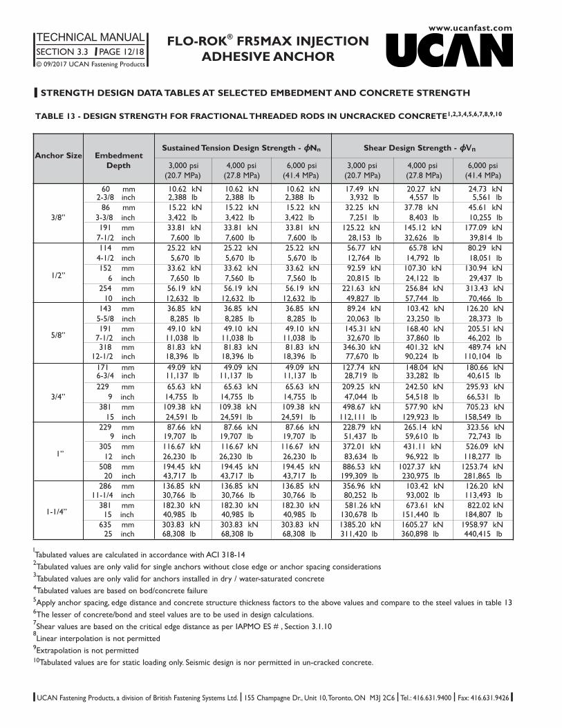
TABLE 13 - DESIGN STRENGTH FOR FRACTIONAL THREADED RODS IN UNCRACKED CONCRETE1,2,3,4,5,6,7,8,9,10
l STRENGTH DESIGN DATA TABLES AT SELECTED EMBEDMENT AND CONCRETE STRENGTH
ITabulated values are calculated in accordance with ACI 318-142Tabulated values are only valid for single anchors without close edge or anchor spacing considerations3Tabulated values are only valid for anchors installed in dry / water-saturated concrete4Tabulated values are based on bod/concrete failure5Apply anchor spacing, edge distance and concrete structure thickness factors to the above values and compare to the steel values in table 136The lesser of concrete/bond and steel values are to be used in design calculations.7Shear values are based on the critical edge distance as per IAPMO ES # , Section 3.1.108Linear interpolation is not permitted
9Extrapolation is not permitted10Tabulated values are for static loading only. Seismic design is nor permitted in un-cracked concrete.
www.ucanfast.comFLO-ROK® FR5MAX INJECTION
ADHESIVE ANCHORTECHNICAL MANUALSECTION 3.3 PAGE 13/18© 09/2017 UCAN Fastening Products
UCAN Fastening Products, a division of British Fastening Systems Ltd. 155 Champagne Dr., Unit 10, Toronto, ON M3J 2C6 Tel.: 416.631.9400 Fax: 416.631.9426
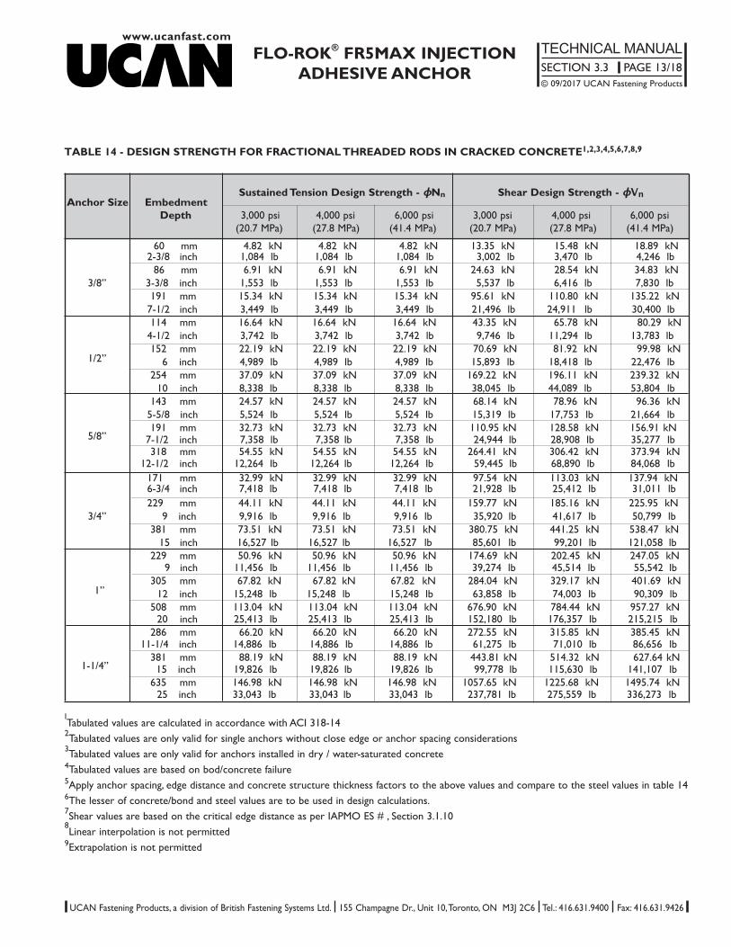
TABLE 14 - DESIGN STRENGTH FOR FRACTIONAL THREADED RODS IN CRACKED CONCRETE1,2,3,4,5,6,7,8,9
ITabulated values are calculated in accordance with ACI 318-142Tabulated values are only valid for single anchors without close edge or anchor spacing considerations3Tabulated values are only valid for anchors installed in dry / water-saturated concrete4Tabulated values are based on bod/concrete failure5Apply anchor spacing, edge distance and concrete structure thickness factors to the above values and compare to the steel values in table 146The lesser of concrete/bond and steel values are to be used in design calculations.7Shear values are based on the critical edge distance as per IAPMO ES # , Section 3.1.108Linear interpolation is not permitted
9Extrapolation is not permitted
Sustained Tension Design Strength - ɸNn Shear Design Strength - ɸVnAnchor Size Embedment
Depth 3,000 psi 4,000 psi 6,000 psi 3,000 psi 4,000 psi 6,000 psi (20.7 MPa) (27.8 MPa) (41.4 MPa) (20.7 MPa) (27.8 MPa) (41.4 MPa)
60 mm 4.82 kN 4.82 kN 4.82 kN 13.35 kN 15.48 kN 18.89 kN2-3/8 inch 1,084 lb 1,084 lb 1,084 lb 3,002 lb 3,470 lb 4,246 lb
86 mm 6.91 kN 6.91 kN 6.91 kN 24.63 kN 28.54 kN 34.83 kN3/8” 3-3/8 inch 1,553 lb 1,553 lb 1,553 lb 5,537 lb 6,416 lb 7,830 lb
191 mm 15.34 kN 15.34 kN 15.34 kN 95.61 kN 110.80 kN 135.22 kN7-1/2 inch 3,449 lb 3,449 lb 3,449 lb 21,496 lb 24,911 lb 30,400 lb114 mm 16.64 kN 16.64 kN 16.64 kN 43.35 kN 65.78 kN 80.29 kN
4-1/2 inch 3,742 lb 3,742 lb 3,742 lb 9,746 lb 11,294 lb 13,783 lb152 mm 22.19 kN 22.19 kN 22.19 kN 70.69 kN 81.92 kN 99.98 kN
1/2” 6 inch 4,989 lb 4,989 lb 4,989 lb 15,893 lb 18,418 lb 22,476 lb254 mm 37.09 kN 37.09 kN 37.09 kN 169.22 kN 196.11 kN 239.32 kN
10 inch 8,338 lb 8,338 lb 8,338 lb 38,045 lb 44,089 lb 53,804 lb143 mm 24.57 kN 24.57 kN 24.57 kN 68.14 kN 78.96 kN 96.36 kN
5-5/8 inch 5,524 lb 5,524 lb 5,524 lb 15,319 lb 17,753 lb 21,664 lb191 mm 32.73 kN 32.73 kN 32.73 kN 110.95 kN 128.58 kN 156.91 kN
5/8” 7-1/2 inch 7,358 lb 7,358 lb 7,358 lb 24,944 lb 28,908 lb 35,277 lb318 mm 54.55 kN 54.55 kN 54.55 kN 264.41 kN 306.42 kN 373.94 kN
12-1/2 inch 12,264 lb 12,264 lb 12,264 lb 59,445 lb 68,890 lb 84,068 lb 171 mm 32.99 kN 32.99 kN 32.99 kN 97.54 kN 113.03 kN 137.94 kN6-3/4 inch 7,418 lb 7,418 lb 7,418 lb 21,928 lb 25,412 lb 31,011 lb229 mm 44.11 kN 44.11 kN 44.11 kN 159.77 kN 185.16 kN 225.95 kN
3/4” 9 inch 9,916 lb 9,916 lb 9,916 lb 35,920 lb 41,617 lb 50,799 lb381 mm 73.51 kN 73.51 kN 73.51 kN 380.75 kN 441.25 kN 538.47 kN
15 inch 16,527 lb 16,527 lb 16,527 lb 85,601 lb 99,201 lb 121,058 lb229 mm 50.96 kN 50.96 kN 50.96 kN 174.69 kN 202.45 kN 247.05 kN
9 inch 11,456 lb 11,456 lb 11,456 lb 39,274 lb 45,514 lb 55,542 lb305 mm 67.82 kN 67.82 kN 67.82 kN 284.04 kN 329.17 kN 401.69 kN
1” 12 inch 15,248 lb 15,248 lb 15,248 lb 63,858 lb 74,003 lb 90,309 lb508 mm 113.04 kN 113.04 kN 113.04 kN 676.90 kN 784.44 kN 957.27 kN
20 inch 25,413 lb 25,413 lb 25,413 lb 152,180 lb 176,357 lb 215,215 lb286 mm 66.20 kN 66.20 kN 66.20 kN 272.55 kN 315.85 kN 385.45 kN
11-1/4 inch 14,886 lb 14,886 lb 14,886 lb 61,275 lb 71,010 lb 86,656 lb381 mm 88.19 kN 88.19 kN 88.19 kN 443.81 kN 514.32 kN 627.64 kN
1-1/4” 15 inch 19,826 lb 19,826 lb 19,826 lb 99,778 lb 115,630 lb 141,107 lb635 mm 146.98 kN 146.98 kN 146.98 kN 1057.65 kN 1225.68 kN 1495.74 kN
25 inch 33,043 lb 33,043 lb 33,043 lb 237,781 lb 275,559 lb 336,273 lb

www.ucanfast.com
FLO-ROK® FR5MAX INJECTIONADHESIVE ANCHOR
TECHNICAL MANUALSECTION 3.3 PAGE 14/18© 09/2017 UCAN Fastening Products
UCAN Fastening Products, a division of British Fastening Systems Ltd. 155 Champagne Dr., Unit 10, Toronto, ON M3J 2C6 Tel.: 416.631.9400 Fax: 416.631.9426
Sustained Tension Design Strength - Nr Shear Design Strength - VrAnchor Size Embedment
Depth 3,625 psi 4,350 psi 5,800 psi 3,625 psi 4,350 psi 5,800 psi (25 Mpa) (30 Mpa) (40 Mpa) (25 Mpa) (30 Mpa) (40 Mpa)
115 mm 24.52 kN 24.52 kN 24.52 kN 57.81 kN 63.33 kN 73.13 kN4-1/2 inch 5,512 lb 5,512 lb 5,512 lb 12,997 lb 14,238 lb 16,440 lb180 mm 38.37 kN 38.37 kN 38.37 kN 123.82 kN 135.64 kN 156.62 kN
10M 7-1/8 inch 3,422 lb 3,422 lb 3,422 lb 27,837 lb 30,494 lb 35,212 lb226 mm 48.18 kN 48.18 kN 48.18 kN 182.31 kN 199.71 kN 230.61 kN
8-7/8 inch 10,832 lb 10,832 lb 10,832 lb 40,987 lb 44,899 lb 51,845 lb145 mm 35.48 kN 35.48 kN 35.48 kN 93.46 kN 102.38 kN 118.22 kN
5-1/2 inch 7,978 lb 7,978 lb 7,978 lb 21,012 lb 23,018 lb 26,578 lb250 mm 61.18 kN 61.18 kN 61.18 kN 235.94 kN 258.46 kN 298.45 kN
15M 9-7/8 inch 13,754 lb 13,754 lb 13,754 lb 53,045 lb 58,108 lb 67,097 lb320 mm 78.31 kN 78.31 kN 78.31 kN 358.98 kN 393.24 kN 454.07 kN
12-5/8 inch 17,606 lb 17,606 lb 17,606 lb 80,705 lb 88,408 lb 102,084 lb200 mm 56.28 kN 56.28 kN 56.28 kN 172.64 kN 189.11 kN 218.37 kN
7-7/8 inch 12,653 lb 12,653 lb 12,653 lb 38,812 lb 42,517 lb 49,094 lb355 mm 99.89 kN 99.89 kN 99.89 kN 457.90 kN 501.60 kN 579.20 kN
20M 14 inch 22,458 lb 22,458 lb 22,458 lb 102,945 lb 112,771 lb 130,216 lb390 mm 109.74 kN 109.74 kN 109.74 kN 537.27 kN 588.55 kN 678.50 kN
15-3/8 inch 24,672 lb 24,672 lb 24,672 lb 120,789 lb 132,318 lb 152,787 lb 230 mm 84.14 kN 84.14 kN 84.14 kN 236.87 kN 259.47 kN 299.61 kN
9 inch 18,916 lb 18,916 lb 18,916 lb 53,252 lb 58,335 lb 67,359 lb405 mm 148.63 kN 160.65 kN 160.65 kN 619.78 kN 678.94 kN 783.97 kN
25M 16 inch 33,308 lb 36,117 lb 36,117 lb 139,339 lb 152,639 lb 176,252 lb504 mm 184.37 kN 184.37 kN 184.37 kN 898.87 kN 984.66 kN 1136.99 kN
19-7/8 inch 41,450 lb 41,450 lb 41,450 lb 202,084 lb 221,372 lb 255,619 lb260 mm 109.74 kN 109.74 kN 109.74 kN 304.55 kN 333.62 kN 385.23 kN
10 inch 24,672 lb 24,672 lb 24,672 lb 68,470 lb 75,005 lb 86,608 lb455 mm 192.05 kN 192.05 kN 192.05 kN 788.55 kN 863.81 kN 997.45 kN
30M 12 inch 43,117 lb 43,117 lb 43,117 lb 177,282 lb 194,203 lb 224,246 lb600 mm 253.25 kN 253.25 kN 253.25 kN 1262.02 kN 1382.48 kN 1596.35 kN
23-5/8 inch 56,936 lb 56,936 lb 56,936 lb 283,728 lb 310,808 lb 358,891 lb
TABLE 15 - DESIGN STRENGTH FOR GRADE 400 CAN REINFORCING BARS IN UNCRACKED CONCRETE1,2,3,4,5,6,7,8,9,10
ITabulated Nr and Vr (factored resistance) values are calculated in accordance with CSA A23.3-14 Annex D2Tabulated values are only valid for single anchors without close edge or anchor spacing considerations3Tabulated values are only valid for anchors installed in dry / water-saturated concrete4Tabulated values are based on bod/concrete failure5Apply anchor spacing, edge distance and concrete structure thickness factors to the above values and compare to the steel values in table 7b6The lesser of concrete/bond and steel values are to be used in design calculations.7CSA G30.18 Grade 400 reinforcing bar are considered ductile steel elements8Linear interpolation is not permitted
9Extrapolation is not permitted10Tabulated values are for static loading only. Seismic design is nor permitted in un-cracked concrete.

www.ucanfast.comFLO-ROK® FR5MAX INJECTION
ADHESIVE ANCHORTECHNICAL MANUALSECTION 3.3 PAGE 15/18© 09/2017 UCAN Fastening Products
UCAN Fastening Products, a division of British Fastening Systems Ltd. 155 Champagne Dr., Unit 10, Toronto, ON M3J 2C6 Tel.: 416.631.9400 Fax: 416.631.9426
Sustained Tension Design Strength - Nr Shear Design Strength - VrAnchor Size Embedment
Depth 3,625 psi 4,350 psi 5,800 psi 3,625 psi 4,350 psi 5,800 psi (25 Mpa) (30 Mpa) (40 Mpa) (25 Mpa) (30 Mpa) (40 Mpa)
115 mm 11.64 kN 11.64 kN 11.64 kN 41.29 kN 45.24 kN 52.23 kN4-1/2 inch 2,617 lb 2,617 lb 2,617 lb 9,284 lb 10,173 lb 11,743 lb180 mm 18.22 kN 18.22 kN 18.22 kN 88.44 kN 96.88 kN 156.62 kN
10M 7-1/8 inch 4,095 lb 4,095 lb 4,095 lb 19,884 lb 21,782 lb 25,151 lb226 mm 22.87 kN 22.87 kN 22.87 kN 130.22 kN 142.65 kN 164.72 kN
8-7/8 inch 5,142 lb 5,142 lb 5,142 lb 29,277 lb 32,071 lb 37,032 lb145 mm 25.11 kN 25.11 kN 25.11 kN 66.76 kN 73.13 kN 84.44 kN
5-1/2 inch 5,645 lb 5,645 lb 5,645 lb 15,009 lb 16,441 lb 18,985 lb250 mm 43.29 kN 43.29 kN 43.29 kN 168.53 kN 184.62 kN 213.18 kN
15M 9-7/8 inch 9,733 lb 9,733 lb 9,733 lb 37,889 lb 41,505 lb 47,926 lb320 mm 55.41 kN 55.41 kN 55.41 kN 256.41 kN 280.88 kN 324.34 kN
12-5/8 inch 12,458 lb 12,458 lb 12,458 lb 57,646 lb 63,148 lb 72,917 lb200 mm 40.68 kN 40.68 kN 40.68 kN 123.31 kN 135.08 kN 155.98 kN
7-7/8 inch 9,145 lb 9,145 lb 9,145 lb 27,723 lb 30,369 lb 35,067 lb355 mm 71.91 kN 71.91 kN 71.91 kN 327.07 kN 358.29 kN 413.72 kN
20M 14 inch 16,167 lb 16,167 lb 16,167 lb 73,532 lb 80,551 lb 93,012 lb390 mm 79.00 kN 79.00 kN 79.00 kN 383.76 kN 420.39 kN 485.43 kN
15-3/8 inch 17,761 lb 17,761 lb 17,761 lb 86,278 lb 94,513 lb 109,134 lb 230 mm 52.39 kN 52.39 kN 52.39 kN 169.19 kN 185.34 kN 214.01 kN
9 inch 11,778 lb 11,778 lb 11,778 lb 38,037 lb 41,668 lb 48,114 lb405 mm 92.25 kN 92.25 kN 92.25 kN 442.70 kN 484.96 kN 559.98 kN
25M 16 inch 20,739 lb 20,739 lb 20,739 lb 99,528 lb 109,028 lb 125,894 lb504 mm 114.80 kN 114.80 kN 114.80 kN 642.05 kN 703.33 kN 812.14 kN
19-7/8 inch 25,808 lb 25,808 lb 25,808 lb 144,346 lb 158,123 lb 182,585 lb260 mm 56.86 kN 56.86 kN 56.86 kN 217.54 kN 238.30 kN 275.17 kN
10 inch 12,784 lb 12,784 lb 12,784 lb 48,907 lb 53,575 lb 61,863 lb455 mm 99.51 kN 99.51 kN 99.51 kN 563.25 kN 617.01 kN 712.46 kN
30M 12 inch 22,372 lb 22,372 lb 22,372 lb 126,630 lb 38,716 lb 160,176 lb600 mm 131.22 kN 131.22 kN 131.22 kN 901.44 kN 987.48 kN 1140.25 kN
23-5/8 inch 29,501 lb 29,501 lb 29,501 lb 202,663 lb 222,006 lb 256,350 lb
TABLE 16 - DESIGN STRENGTH FOR GRADE 400 CAN REINFORCING BARS IN CRACKED CONCRETE1,2,3,4,5,6,7,8,9
ITabulated Nr and Vr (factored resistance) values are calculated in accordance with CSA A23.3-14 Annex D2Tabulated values are only valid for single anchors without close edge or anchor spacing considerations3Tabulated values are only valid for anchors installed in dry / water-saturated concrete4Tabulated values are based on bod/concrete failure5Apply anchor spacing, edge distance and concrete structure thickness factors to the above values and compare to the steel values in table 7b6The lesser of concrete/bond and steel values are to be used in design calculations.7CSA G30.18 Grade 400 reinforcing bar are considered ductile steel elements8Linear interpolation is not permitted
9Extrapolation is not permitted
www.ucanfast.com
FLO-ROK® FR5MAX INJECTIONADHESIVE ANCHOR
TECHNICAL MANUALSECTION 3.3 PAGE 16/18© 09/2017 UCAN Fastening Products
UCAN Fastening Products, a division of British Fastening Systems Ltd. 155 Champagne Dr., Unit 10, Toronto, ON M3J 2C6 Tel.: 416.631.9400 Fax: 416.631.9426
lALLOWABLE STRESS DESIGN (ASD)
For anchors designed using load combinations calculated in accordance with IBC Section 1605.3 (Allowable Stress Design), allowable loadsmust be established using the fallowing relationships:
T allowable, ASD = φNn/aV allowable, ASD = φVn/a where
T allowable, ASD = Allowable tension load (lbf or kN)V allowable, ASD = Allowable shear load (lbf or kN)
φNn = The lowest design strength for an anchor or anchor group in tension as determined in accordance with ACI 318 Appendix D as amended in the IAPMO ES # report and 2009 IBC Sections 1908.1.9 and 1908.1.10 or 2006 IBC Section 1908.1.16, as applicable.
φVn = The lowest design strength for an anchor or anchor group in shear as determined in accordance with ACI 318 Appendix D as amended in the IAPMO ES # report and 2009 IBC Sections 1908.1.9 and 1908.1.10 or 2006 IBC Section 1908.1.16, as applicable.
a = Conversion factor calculated as a weighted average of the load factors for the controlling load combination. In addition, a must include allapplicable factors to account for non-ductile failure modes and required over-strength.
The requirements for member thickness, edge distance and spacing, as described in Table 1, must apply.
Interaction of Tensile and Shear Forces
In lieu of ACI Sections D.7.1, D.7.2 and D.7.3, interaction of tension and shear loads must be calculated as follows:
For tension loads T ≤ 0.2 Tallowable, ASD, the full allowable strength in shear, Vallowable, ASD, shall be permitted.For shear loads V ≤ 0.2 Vallowable, ASD, the full allowable strength in tension, Tallowable, ASD, shall be permitted.For all other cases:
T + V ≤ 1.2T allowable,ASD V allowable, ASD
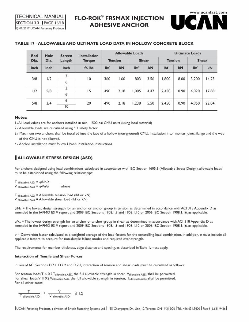
TABLE 17 - ALLOWABLE AND ULTIMATE LOAD DATA IN HOLLOW CONCRETE BLOCK
Rod Hole Screen InstallationAllowable Loads Ultimate Loads
Dia. Dia. Length Torque Tension Shear Tension Shear
inch inch inch ft. lbs lbf kN lbf kN lbf kN lbf kN
3/8 1/23
10 360 1.60 803 3.56 1,800 8.00 3,200 14.236
1/2 5/83
15 490 2.18 1,005 4.47 2,450 10.90 4,020 17.886
5/8 3/46
20 490 2.18 1,238 5.50 2,450 10.90 4,950 22.0410
Notes:1./All load values are for anchors installed in min. 1500 psi CMU units (using local material)2./ Allowable loads are calculated using 5:1 safety factor3./ Maximum two anchors shall be installed into the face of a hollow (non-grouted) CMU. Installation into mortar joints, flange and the web
of the CMU is not allowed.4./ Anchor installation must follow Ucan’s installation instructions.

www.ucanfast.comFLO-ROK® FR5MAX INJECTION
ADHESIVE ANCHORTECHNICAL MANUALSECTION 3.3 PAGE 17/18© 09/2017 UCAN Fastening Products
UCAN Fastening Products, a division of British Fastening Systems Ltd. 155 Champagne Dr., Unit 10, Toronto, ON M3J 2C6 Tel.: 416.631.9400 Fax: 416.631.9426
l CHEMICAL RESISTANCE
The chemical mortar has undergone extensive chemical resistance testing. The results are summarised in the table below.
Chemical Environment Concentration Result
Aqueous Solution Acetic Acid 10% ✓Acetone 100% ✗
Aqueous Solution Aluminium Chloride Saturated ✓Aqueous Solution Aluminium Nitrate 10% ✓Ammonia Solution 5% ✓Jet Fuel 100% ✓Benzene 100% ✗Benzoic Acid Saturated ✓Benzyl Alcohol 100% ✗Sodium Hypochlorite Solution 5 - 15% C
Butyl Alcohol 100% C
Calcium Sulphate Aqueous Solution Saturated ✓Carbon Monoxide Gas ✓Carbon Tetrachloride 100% ✓Chlorine Water Saturated ✓Chloro Benzene 100% ✗Citric Acid Aqueous Solution Saturated ✓Cyclohexanol 100% ✓Diesel Fuel 100% ✓Diethylene Glycol 100% ✓Ethanol 95% C
Ethanol Aqueous Solution 20% C
Heptane 100% ✓
Chemical Environment Concentration Result
Hexane 100% C
10% ✓Hydrochloric Acid 15% ✓
25% C
Hydrogen Sulphide Gas 100% ✓Isoproyl Alcohol 100% C
Linseed Oil 100% ✓Lubricating Oil 100% ✓Mineral Oil 100% ✓Paraffin / Kerosene (Domestic) 100% ✓Phenol Aqueous Solution 1% ✗Phosphoric Acid 50% ✓Potassium Hydroxide 10% / pH13 C
Sea Water 100% ✓Styrene 100% ✗Sulphur Dioxide Solution 10% ✓Sulphur Dioxide (40°C) 5% ✓
10% ✓Sulphuric Acid
50% ✓Turpentine 100% C
White Spirit 100% ✓Xylene 100% ✗
✓= Resistant to 75°C with at least 80% of physicalproperties retained.
C = Contact only to a maximun of 25°C.✗= Not Resistant.

www.ucanfast.com
FLO-ROK® FR5MAX INJECTIONADHESIVE ANCHOR
TECHNICAL MANUALSECTION 3.3 PAGE 18/18© 09/2017 UCAN Fastening Products
UCAN Fastening Products, a division of British Fastening Systems Ltd. 155 Champagne Dr., Unit 10, Toronto, ON M3J 2C6 Tel.: 416.631.9400 Fax: 416.631.9426
l EPOXY USAGE ESTIMATING TABLES1
TABLE 18 - Holes per FR5MAX–10
Rod Hole Embedment (inch)dia. dia. 1 2 3 4 5 6 7 8 9 10 15 20
1/4 5/16 302.1 151.1 100.7 75.5 60.4 50.4 43.2 37.8 33.6 30.2 20.1 15.13/8 178.8 89.4 59.6 44.7 35.8 29.8 25.5 22.4 19.9 17.9 11.9 8.9
3/8 7/16 182.4 91.2 60.8 45.6 36.5 30.4 26.1 22.8 20.3 18.2 12.2 9.11/2 117.1 58.5 39.0 29.3 23.4 19.5 16.7 14.6 13.0 11.7 7.8 5.9
1/2 9/16 131.6 65.8 43.9 32.9 26.3 21.9 18.8 16.5 14.6 13.2 8.8 6.65/8 84.7 42.4 28.2 21.2 16.9 14.1 12.1 10.6 9.4 8.5 5.6 4.2
5/8 11/16 96.2 48.1 32.1 24.1 19.2 16.0 13.7 12.0 10.7 9.6 6.4 4.83/4 65.9 33.0 22.0 16.5 13.2 11.0 9.4 8.2 7.3 6.6 4.4 3.3
3/4 13/16 77.2 38.6 25.7 19.3 15.4 12.9 11.0 9.7 8.6 7.7 5.1 3.97/8 54.5 27.3 18.2 13.6 10.9 9.1 7.8 6.8 6.1 5.5 3.6 2.7
7/8 61/64 67.1 33.5 22.4 16.8 13.4 11.2 9.6 8.4 7.5 6.7 4.5 3.41 44.5 22.3 14.8 11.1 8.9 7.4 6.4 5.6 4.9 4.5 3.0 2.2
TABLE 19 - Holes per FR5MAX–28
Rod Hole Embedment (inch)dia. dia. 1 2 3 4 5 6 7 8 9 10 15 20
1/4 5/16 891.9 446.0 297.3 223.0 178.4 148.7 127.4 111.5 99.1 89.2 59.5 44.63/8 27.9 264.0 176.0 132.0 105.6 88.0 75.4 66.0 58.7 52.8 35.2 26.4
3/8 7/16 538.3 269.2 179.4 134.6 107.7 89.7 76.9 67.3 59.8 53.8 35.9 26.91/2 345.6 172.8 115.2 86.4 69.1 57.6 49.4 43.2 38.4 34.6 23.0 17.3
1/2 9/16 388.5 194.3 129.5 97.1 77.7 64.8 55.5 48.6 43.2 38.9 25.9 19.45/8 250.1 125.0 83.4 62.5 50.0 41.7 35.7 31.3 27.8 25.0 16.7 12.5
5/8 11/16 284.0 142.0 94.7 71.0 56.8 47.3 40.6 35.5 31.6 28.4 18.9 14.23/4 194.6 97.3 64.9 48.7 38.9 32.4 27.8 24.3 21.6 19.5 13.0 9.7
3/4 13/16 228.0 114.0 76.0 57.0 45.6 38.0 32.6 28.5 25.3 22.8 15.2 11.47/8 161.0 80.5 53.7 40.2 32.2 26.8 23.0 20.1 17.9 16.1 10.7 8.0
7/8 61/64 198.0 99.0 66.0 49.5 39.6 33.0 28.3 24.7 22.0 19.8 13.2 9.91 131.5 65.7 43.8 32.9 26.3 21.9 18.8 16.4 14.6 13.1 8.8 6.6
1 1 1/16 143.9 72.0 48.0 36.0 28.8 24.0 20.6 18.0 16.0 14.4 9.6 7.21 1/8 108.1 54.1 36.0 27.0 21.6 18.0 15.4 13.5 12.0 10.8 7.2 5.4
1 1/4 1 3/8 83.7 41.9 27.9 20.9 16.7 14.0 12.0 10.5 9.3 8.4 5.6 4.21 1/2 55.0 27.5 18.3 13.8 11.0 9.2 7.9 6.9 6.1 5.5 3.7 2.8
Rebar size10M 9/16 391.6 195.8 130.5 97.9 78.3 65.3 55.9 49.0 43.5 39.2 26.1 19.615M 3/4 268.4 134.2 89.5 67.1 53.7 44.7 38.3 33.6 29.8 26.8 17.9 13.420M 61/64 173.8 86.9 57.9 43.4 34.8 29.0 24.8 21.7 19.3 17.4 11.6 8.725M 1 1/4 84.7 42.3 28.2 21.2 16.9 14.1 12.1 10.6 9.4 8.5 5.6 4.230M 1 1/2 58.8 29.4 19.6 14.7 11.8 9.8 8.4 7.3 6.5 5.9 3.9 2.935M 1 3/4 48.3 24.2 16.1 12.1 9.7 8.1 6.9 6.0 5.4 4.8 3.2 2.4
1For correct epoxy usage, add 20% waste (multiply the tabulated number by 0.80)