uas atm cars atm cars edition: 1.0 4 table of contents executive summary 6 1 introduction
TRANSCRIPT
UAS ATM CARS
Common Altitude Reference System Discussion Document
UAS ATM CARS
Common Altitude Reference System Discussion Document
European Organisation for the Safety of the Air Navigation (EUROCONTROL) Directorate of European Civil-Military Aviation (DECMA) Aviation Cooperation and Strategies Division (ACS) Edition: 1.0 Edition date: 27th November 2018
UAS ATM CARS
Edition: 1.0 3
DOCUMENT CONTROL
DISCLAIMER
© 2018 European Organisation for the Safety of Air Navigation (EUROCONTROL).
This Report makes use of information provided to EUROCONTROL by third parties.
All third party content was obtained from sources believed to be reliable and was accurately
reproduced in the report at the time of printing. However, EUROCONTROL specifically does not make
any warranties or representations as to the accuracy, completeness, or timeliness of such information
and accepts no liability or responsibility arising from reliance upon or use of the same. The views
expressed in this report do not necessarily reflect individual or collective opinions or official positions
of EUROCONTROL Member States.
Note
This document has been developed by EUROCONTROL in partnership with the European Aviation
Safety Agency (EASA) through several webinars. The authors would like to thank the participants in
these webinars for their valuable contributions.
Intellectual property rights and reprint rights apply.
CONTACT PERSON
Name Unit E-mail
Peter Hullah DECMA/RTD/PPU [email protected]
DOCUMENT CHANGE RECORD
Edition No. Edition Date Reason for Change
1.0 27/11/2018 Initial Release
DOCUMENT APPROVAL
Name Role Unit
Paul Bosman Head of Division DECMA/ACS
Mike Lissone UAS ATM Integration Manager DECMA/ACS
UAS ATM CARS
Edition: 1.0 4
TABLE OF CONTENTS
EXECUTIVE SUMMARY ............................................................................................................................ 6
1 Introduction..................................................................................................................... 7
1.1 Intended Audience .................................................................................................................. 7
1.2 Organisation of this document ............................................................................................... 7
2 The problem .................................................................................................................... 8
2.1 Aircraft separation .................................................................................................................. 8
2.2 UAS altimetry .......................................................................................................................... 9
2.3 Sources of height/altitude discrepancy .................................................................................. 9
2.4 Very Low-Level airspace ........................................................................................................ 10
2.5 Main areas of concern .......................................................................................................... 11
3 Guidelines for a Common Altitude Reference System (CARS) ...................................... 12
3.1 Separating VLOS from other traffic ....................................................................................... 12
3.2 The need for a CARS .............................................................................................................. 12
3.3 Reference datum .................................................................................................................. 13
3.3.1 Home point .................................................................................................................... 13
3.3.2 WGS84 ........................................................................................................................... 13
3.4 Technologies ......................................................................................................................... 14
3.4.1 Barometric pressure ...................................................................................................... 14
3.4.2 TCAS/ACAS .................................................................................................................... 15
3.4.3 GNSS-based techniques ................................................................................................ 15
3.5 Implementation .................................................................................................................... 15
3.5.1 General implementation observations ......................................................................... 15
3.5.2 Maximum heights and a boundary layer ...................................................................... 16
3.5.3 Data accuracy, reliability and integrity .......................................................................... 16
4 Conclusions.................................................................................................................... 17
4.1 Introduction .......................................................................................................................... 17
4.2 Options for a CARS ................................................................................................................ 17
4.2.1 Option 1: All local VLL operations use barometric altimetry based on local QNH; no UTM
functionalities are used ................................................................................................. 18
4.2.2 Option 2: All local VLL operations use GNSS-based altimetry; no UTM functionalities are
used ............................................................................................................................... 18
4.2.3 Option 3: Each airspace user will use an approved altimetry system best suited to the
airspace or certification requirements, and UTM functionalities are used. ................. 19
4.3 Research and development requirements ........................................................................... 20
5 References ..................................................................................................................... 22
Appendix 1 Using UTM to mitigate differences between different altitude systems ...................... 23
Definitions, Acronyms and Abbreviations ............................................................................................ 26
UAS ATM CARS
Edition: 1.0 5
LIST OF FIGURES
Figure 1 - 3 different height/altitude measurement options ................................................................. 8
Figure 2 - The effect of a drone's "home point" specification ............................................................. 10
Figure 3 - UTM based calibrated vertical separation calculation Δh .................................................... 23
Figure 4 - Barometric-barometric altitudes received by UTM .............................................................. 24
Figure 5 - Barometric-GNSS altitudes received by UTM ....................................................................... 24
Figure 6 - GNSS-GNSS altitudes received by UTM ................................................................................ 25
LIST OF TABLES
Table 1 - Definitions, acronyms, and abbreviations ............................................................................. 27
UAS ATM CARS
Edition: 1.0 6
EXECUTIVE SUMMARY
The many activities for which unmanned air systems (UAS) are used – from military through
commercial to leisure – can lead to their sharing airspace with conventional aircraft. For separation to
be maintained between all users of this airspace, it is essential that the altitudes of all of these aircraft
be known unambiguously.
However, whereas conventional manned aviation uses pressure altitude obtained from barometric
readings, UAS often use other systems such as satellite-derived altitudes. While each of these different
systems can enable safe separation on its own, they can each furnish different altitude values from
each other. A common altitude reference system needs to be established.
This document provides a basis for discussion on such a system, following a workshop and a series of
webinars organised by EUROCONTROL in collaboration with the European Aviation Safety Agency
(EASA).
There are many advantages and disadvantages, economic and technical, to all of the altitude
measurement systems available. In the conclusions of this document, a solution is proposed that will
enable two different systems to co-habit safely.
UAS ATM CARS
Edition: 1.0 7
1 INTRODUCTION
This is one of a collection of three documents discussing distinct points raised in the 1st UAS-ATM
Integration Workshop organised at EUROCONTROL Brussels in April 2017. The purpose of this
workshop was to discuss the problems associated with integrating Unmanned Aircraft Systems (UAS)
- colloquially called "Drones" - including Remotely-Piloted Aircraft Systems (RPAS), into the airspace
that also includes many manned flights and, therefore, presents a definite safety hazard.
The three distinct points are:
• Flight rules;
• Airspace, or operating environment, assessment;
• A common altitude reference system (this document).
Following on from the above-mentioned workshop, a series of webinars were organised in the first
half of 2018 to enable interested stakeholders to express their points of view on these questions, to
offer solutions where possible, and most importantly to ensure a “common understanding” on any
issues related to the topic.
The outcome of these discussions, presented here, is a proposal for guidelines on establishing a
common altitude reference system, part of a joint approach between EUROCONTROL and EASA to
develop a UAS Integration manual and the joint EUROCONTROL/EASA UAS ATM Operational Concept
document, and will be taken into account in the Concept of Operations produced by the on-going
CORUS project.
1.1 INTENDED AUDIENCE
This document is primarily for use by stakeholders interested in understanding the problem and
solution set out herein. This can include civil aviation authorities, Air Navigation Service Providers
(ANSPs), Unmanned Traffic Management (UTM) system providers, drone manufacturers, etc.
However, it is hopefully written in a way that is also accessible to any layman interested the problems
related to integrating UAS into the airspace.
1.2 ORGANISATION OF THIS DOCUMENT
After this introduction, section 2 specifies the problem statement and any specificities to this problem,
together with background information. Section 3 gives a discussion on the different technical systems
available for altitude/height measurement and section 4 provides a possible solution as a conclusion..

UAS ATM CARS
Edition: 1.0 8
2 THE PROBLEM
There are currently three acknowledged methods of determining the altitude of an aircraft using a
pressure difference with respect to a known datum, using standard equipment, within the
International Standard Atmosphere (ISA).
• QFE - height above the local airport etc. ("home point");
• QNH - altitude above a given reference mean sea level (MSL), based on the current air pressure
at a regional point of reference;
• Flight Level (FL) - A surface of constant atmospheric pressure relative to a specific pressure
datum, 1013.2hPa (defined as 0FL), and separated from other such surfaces by specific pressure
intervals. One FL is the pressure differential of a 100ft altitude change in the International
Standard Atmosphere [ISO, 1975].
Figure 1 shows these three methods.
Figure 1 - 3 different height/altitude measurement options
• It is now also possible to measure height using GNSS or its augmentations GBAS or SBAS. In civil
aviation, for example, RNP approaches using SBAS have their vertical guidance based on the
outputs of a GNSS receiver (in the WGS84 reference system). Such systems are not yet in wide
use by general aviation and other users of VLL airspace.
2.1 AIRCRAFT SEPARATION
In article 3.2 of the ICAO "Application of Separation Minima - North Atlantic Region" document [ICAO,
2017], the minimum vertical separation between aircraft, airspace reservations, and between airspace
reservations and other aircraft are given as:
UAS ATM CARS
Edition: 1.0 9
A. 4000 feet at or above FL 450 between supersonic aircraft, and between supersonic aircraft and any other aircraft,
B. 2000 feet at or above FL 290 between a formation flight and any other aircraft, or
C. 2000 feet at or above FL 290, or
D. 1000 feet from FL 290 to FL 410 inclusive between [Reduced Vertical Separation Minima] RVSM aircraft, or
E. 1000 feet below FL 290
Although these flight-level altitudes may not correspond to the actual altitude above sea level, vertical
separation can be ensured if all aircraft altimeters are calibrated identically.
Closer to the ground, aircraft have to be careful not just to avoid other aircraft, but also terrain and
other obstacles. For this reason, pilots need a datum that will enable them to understand their position
with respect to the ground. Below a particular region-dependent transition level, therefore, they
recalibrate their altimeters to the QNH pressure for the appropriate QNH region.
Again, as long as all aircraft altimeters are similarly calibrated in the same region, vertical separation
can be assured.
2.2 UAS ALTIMETRY
UAS also need altimetry. It is necessary to ensure that they stay within their mandated limits, including
geo-fencing, geo-caging, etc., and for them to avoid hitting obstacles on the ground. However, the
arrival of UAS operations has introduced a new altitude/height challenge: how to ensure separation
between UAS and other aircraft (manned or unmanned) in the same airspace by ensuring they are
using the same height/altitude reference. Although UTM functions such as mission planning, flight
planning, authorisation, geo-fencing, etc. will ensure a certain level of separation, height is a necessary
input to other functions supplied by a UTM system.
Small-UAS altimeters (which are generally GNSS-based) are generally set to 0 at the beginning of each
flight. This start position is generally referred to as the "home point". However, if an aircraft is flying
at, say, 200ft, it is essential that others users in the same airspace volume have the same reference
for 200ft.
2.3 SOURCES OF HEIGHT/ALTITUDE DISCREPANCY
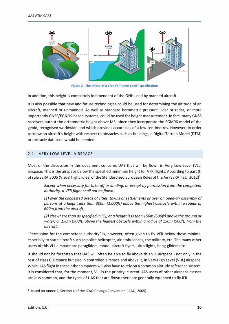
Every UAS can be considered to start from a different "home point". It follows therefore that two UAS
that are flying at the same indicated height are likely to be actually at different true altitudes. As can
be seen in Figure 2 the "height" a given UAS has to attain to clear an obstacle, for example a tall
building, will depend not just on the height of the building, but also on the elevation of the "home
point" compared with the building.
UAS ATM CARS
Edition: 1.0 10
Figure 2 - The effect of a drone's "home point" specification
In addition, this height is completely independent of the QNH used by manned aircraft.
It is also possible that new and future technologies could be used for determining the altitude of an
aircraft, manned or unmanned. As well as standard barometric pressure, lidar or radar, or more
importantly GNSS/EGNOS-based systems, could be used for height measurement. In fact, many GNSS
receivers output the orthometric height above MSL since they incorporate the EGM96 model of the
geoid, recognised worldwide and which provides accuracies of a few centimetres. However, in order
to know an aircraft's height with respect to obstacles such as buildings, a Digital Terrain Model (DTM)
or obstacle database would be needed.
2.4 VERY LOW-LEVEL AIRSPACE
Most of the discussion in this document concerns UAS that will be flown in Very Low-Level (VLL)
airspace. This is the airspace below the specified minimum height for VFR flights. According to part (f)
of rule SERA.5005 (Visual flight rules) of the Standardised European Rules of the Air (SERA) [EU, 2012]1:
Except when necessary for take-off or landing, or except by permission from the competent authority, a VFR flight shall not be flown:
(1) over the congested areas of cities, towns or settlements or over an open-air assembly of persons at a height less than 300m (1,000ft) above the highest obstacle within a radius of 600m from the aircraft;
(2) elsewhere than as specified in (1), at a height less than 150m (500ft) above the ground or water, or 150m (500ft) above the highest obstacle within a radius of 150m (500ft) from the aircraft.
"Permission for the competent authority" is, however, often given to fly VFR below these minima,
especially to state aircraft such as police helicopter, air ambulances, the military, etc. The many other
users of this VLL airspace are paragliders, model-aircraft flyers, ultra-lights, hang-gliders etc.
It should not be forgotten that UAS will often be able to fly above this VLL airspace - not only in the
rest of class G airspace but also in controlled airspace and above it, in Very High Level (VHL) airspace.
While UAS flight in these other airspaces will also have to rely on a common altitude reference system,
it is considered that, for the moment, VLL is the priority; current UAS users of other airspace classes
are less common, and the types of UAS that are flown there are generally equipped to fly IFR.
1 based on Annex 2, Section 4 of the ICAO Chicago Convention [ICAO, 2005]
UAS ATM CARS
Edition: 1.0 11
2.5 MAIN AREAS OF CONCERN
UAS must be able to keep clear of each other, and of manned aircraft using the same airspace. To
ensure vertical separation from these aircraft, it is essential that they use the same altitude reference.
They must also be able to keep clear of objects on the ground - buildings, cranes, trees, etc. - and of
course people and property in general. Their pilots (or their on-board flight controllers) need,
therefore, to be able to understand their height above the ground in an unambiguous way, to be able
to relate this to databases of objects and terrain, and to the declared altitude of other aircraft.
For a UAS Traffic Management (UTM) system to be able to inform air-traffic authorities of the accurate
trajectory of a UAS, it is necessary that the altitude at which the UAS will be flown be transmitted and
adhered to unambiguously. This is especially true when flying in upper limit of VLL airspace and
airspace close to the airports. This is primarily a concern for small UAS operations; larger UAS flying
under IFR must use the same means of defining their altitude as manned aircraft.
This guideline document needs to answer two principal questions:
1. Which technology should be used to measure the altitude at which a UAV is flying, and to what
precision and accuracy?
2. This must be technologically feasible on a UAV and provide an altitude/height value compatible
with other users of the same airspace and with reference data concerning obstacles on the
ground.
3. Which reference datum should be used to ensure that every user of a given airspace is flying in
the same altitude/height reference system?
UAS ATM CARS
Edition: 1.0 12
3 GUIDELINES FOR A COMMON ALTITUDE REFERENCE SYSTEM (CARS)
3.1 SEPARATING VLOS FROM OTHER TRAFFIC
ATM/UTM have as a primary objective maintaining separation between aircraft (manned or
unmanned) and between UAS and obstacles/buildings, although work on Detect and Avoid (DAA)
systems aims to enable such separation to be performed automatically by the UAs. The rules of the
air such as the SERA include articles on rights of way etc. to ensure this separation. However, vertical
separation remains the key to airspace safety and VLOS rules require the remote pilot (RP) to limit the
VLOS height flown to ensure that they are visually able to separate vertically.
The initial view of the EUROCAE DAA group was that, rather than using vertical separation, other
airspace users should simply be avoided in areas where UAS operations are limited to VLL, below
150m. However, the relative speeds of the two aircraft to be separated becomes a major point when
UA are part of the problem. In many cases UAs are stationary or very slow moving and it is not even
clear which direction they are moving in to determine any right of way rules etc.
An RP is barely capable of ensuring separation in VLOS and might not be able to avoid other traffic
such as VFR or BVLOS, even if a DAA system is installed. They will certainly not be able to react in time
to avoid fast moving military traffic. In the future, the roles may be reversed it will be very hard for
low-flying VFR traffic such as HEMA to see very fast (up to 250kts) but relatively small UAs soon
enough.
Strategic vertical separation is going to be key to solving this problem.
3.2 THE NEED FOR A CARS
At present, there are several problems associated with altitude for UAS/manned-aviation: barometric
pressure altitude is not very accurate; current obstacle databases are made for manned aviation; use
of a "home point" for zero reference could lead to a UAs flying in VFR airspace without being aware
of it due to uneven terrain, e.g. flying from a hilltop, etc. Additionally, for traffic separation between
UTM and ATM (150m/500ft), or intra UTM (between 0m and 150m/500ft), visual assessment of
relative height between two flying objects is not accurate enough and a true, qualified measurement
is needed.
Only terrain and obstacle protection are likely to be possible by visual means from the ground. On the
other hand, whereas it might not be critical to have precise measurement equipment on board a UA
flying VLOS, a BVLOS pilot also needs to be able to avoid obstacles on the ground, without the benefit
of line-of-sight.
As stated in 3.1 above, VLOS implies that separation is managed visually by the RP with only their eyes
to assist them and their job is simply to stay out of the way of other traffic. In this case VLOS only need
a means of staying within the normal AGL vertical limit. However, visual separation of one UA from
another one relatively far away is impossible. Additionally, functions like geo-fencing and geo-caging
will assist RPs, so that they do not only rely on their eyes but these functions need to know the height
the UA is flying at. This is especially the case when close to an aerodrome, say, where the height limit
may be variable. Additionally, if a drone goes BVLOS it needs a common reference with the other
UAS ATM CARS
Edition: 1.0 13
aircraft around it. Furthermore, the EASA Opinion requires e-identification and geo-awareness for UAS
Class 1 to 3 in the Open Category. Therefore, geo-data and particularly height data are needed.
In cases like these, it is necessary to have an unequivocal reference for height or altitude
measurement. A CARS is required by VLOS because there are no other means of determining their
altitude and extending this to U-Space. There has to be at least an indication of the altitude for VLOS
operations since even if a block of airspace is reserved by a flight plan, there is no way of visually
determining if a VLOS UAS is within the vertical airspace authorised or not.
Such a CARS implies a need for a common technology for determining height or altitude and the need
for a common datum. This guidance document is a necessary requirement for arriving at these needs.
The reference for safety and performance requirements should be established before reviewing and
selecting a datum and defining requirements for positioning sensor technologies.
It is fundamental that the present document be aligned with the roadmap in Europe. Recent material
issued by EUROCONTROL (Integrated CNS vision, SESAR project 14.01.01) and SJU (SESAR CNS Avionics
and Spectrum Strategy) state that in the future GNSS will be the primary means of navigation.
However, this work is concerned with commercial aviation, and its applicability to low-level flight is
not certain since general aviation was not taken into account.
3.3 REFERENCE DATUM
The starting point for this discussion should be the common altitude reference datum rather than the
technology used, since this datum will determine the map data and altitude. This in turn could
determine the technology required.
3.3.1 HOME POINT
Many UAS use height from the "home point", which poses a problem since the upper limit of VLL, the
lower normal limit of VFR, is 150m/500ft above ground level (AGL). However, ground level is only the
same as the home point at take-off and could vary significantly during a flight.
3.3.2 WGS84
The WGS84 geoid gives the difference between the ellipsoid and the MSL. It is publicly available and
is generally included in most GPS receivers today.
The geometric altitude in WGS84 could be appropriate for all aircraft. Almost all relevant drones
already use WGS84 and SBAS-augmented GNSS - EGNOS is also available. Galileo is already providing
initial services and, as part of the enhanced service declaration, new services such as high accuracy
down to 20cm and authentication, which will increase robustness and resilience against cyber attacks,
will be provided.
Although the WGS 84 ellipsoid is up to 100m different from mean sea level in some parts of the world,
the largest error is in India, not Europe. Separation is still assured if everybody uses the same datum
e.g. everybody flies at -100m. Translation between WGS84 height and AGL altitude should be done by
ATM/UTM or other on-board functions.
UAS ATM CARS
Edition: 1.0 14
Ground-plan databases applicable to UAs should also apply WGS84 to ensure obstacle clearance.
Denmark, for example, uses a publicly available digital height model based on WGS84. It has 1.6m2
resolution and should enable a UAS to know when it is close to any obstacles.
3.4 TECHNOLOGIES
3.4.1 BAROMETRIC PRESSURE
Barometric pressure is, today, the standard method of ensuring separation between aircraft, which
are all equipped to use it and whose pilots are all trained for it. As explained in section 2.1, as long as
two aircraft are flying on different iso-pressure layers, they will not come into conflict. It may be
needed for determining the upper limit of VLL because manned aviation uses it for this.
However, it might not work for avoiding obstacles on the ground. An aircraft/UAV trying to use it to
keep clear of buildings/objects needs the real geometric height of that object, which could be different
from that measured by barometric equipment that assumes a standard atmosphere. If the air is colder,
for example, the pressure levels are compressed and hence the height of an obstacle measured by air
pressure is not the same as the geometric height.
Two aircraft in the same area at the same time should use the same altitude setting. However, BVLOS
flights might not have pressure data available for their entire route and would have to use the ‘regional
QNH’ (i.e. the lowest QNH of a specific set of QNH reporting stations) used by manned aviation. The
nearest QNH could be automatically uplinked to a UA via datalink. For collision avoidance, either VLOS
flights should also use this regional QNH or BVLOS flights should not enter airspace used by VLOS
flights - this is similar to the manned aviation case where en-route aircraft has to remain clear of traffic
patterns at aerodromes.
The need for transmitting the QNH is a clear drawback of barometric height. Additionally, QNH is not
available everywhere, and can be very limited in scope.
Barometric pressure presents many other problems in VLL:
• Atmospheric pressure over cities (probably the most challenging environment and the one that
poses the most risk to the public) is difficult to measure due to high temperature gradients.
Buildings generally radiate heat, in particular when there are large air-conditioning units on top
of them, whereas parks and lakes that could be nearby could be cool. This could considerably
affect the measurement of barometric altitude on UAs/aircraft.
• Air pressure is not constant but changes over time, so the (regional) QNH does as well. If air
pressure is used for de-confliction between different airspace users, UAS may need to be able
to change their QNH-setting in-flight.
• The certified resolution of the barometric measurement in airplanes is 25ft, which is very coarse
for using in VLL. In fact, errors up to 75ft are fairly common.
• It can be difficult to measure air pressure in a UA since the rotors could be quite close to the
pressure sensors and cause constant changes in pressure. In an normal aircraft the sensors are
far away from the propellers.
Other height measurement sensors e.g. sound, light, radio or a geodetic approach could be more
accurate than a barometric one.
UAS ATM CARS
Edition: 1.0 15
3.4.2 TCAS/ACAS
The techniques used in TCAS/ACAS logics could bring useful information though there is uncertainty
concerning the ACAS-Xu reference used on the vertical axis.
3.4.3 GNSS-BASED TECHNIQUES
ICAO is developing the Dual-Frequency, Multi-Constellation (DMFC) GNSS concept, which will have
many technical and operational benefits for civil aviation. The CONOPS and the corresponding Annex
10 SARPs for GNSS systems are currently being developed at the ICAO NSP level. Other standardisation
bodies such as EUROCAE and RTCA are working on the DFMC antenna and receiver MOPS. EGNOS v3
will support the DFMC concept by augmenting GPS and Galileo, and providing corrections on L1 and
L5 frequency bands.
Most small UAS will probably keep a GNSS-only based reference in the near future. Some
manufacturers have already coded a conversion to the manned-aviation reference, but they consider
the pressure sensors used to be error-prone. Conversion between the systems could be automatic in
a U-Space system. Perhaps it would be feasible to introduce GNSS-based altitude to manned aircraft
as well as UAS.
3.4.3.1 GNSS ACCURACY
EGNOS already normally provides accuracy well within 1 metre horizontally and 2 metres vertically
and it has recently been announced that Galileo will provide a high-accuracy service down to 20cm
free of charge. ESSP provides a monthly EGNOS performance report (e.g. [ESSP, 2018]) that deals with
GPS+SBAS vertical accuracy values.
Some UAS already use low cost Real-Time Kinematics (RTK) kits for VLOS and/or "short range", some
use both a digital terrain model and GNSS information, and some of the slower ones merge this with
sensor data. RTK provides centimetre-level accuracies, but needs good quality measurements in order
to fix the ambiguity computation involved in the carrier phase measurement. However, it is
questionable if the UAS market actually needs centimetre-level accuracies.
3.5 IMPLEMENTATION
3.5.1 GENERAL IMPLEMENTATION OBSERVATIONS
Although a common altitude reference is considered absolutely necessary, EASA does not expect any
measurement of UA height for Open-category VLOS operations. It considers it the responsibility of the
operator or the pilot, who might have a limited knowledge of the UA's height, to keep it away from
other airspace users. However, the EASA Opinion [EASA, 2018] says that e-identification and geo-
awareness are required for ‘Open’ category classes C1, C2, and C3, and geo-data data is needed for
both functions. On the other hand, for the "Specific" and "Certified" categories as well as small UAS
used professionally under IFR, the barometric reference should be used, though these UAs will
certainly also be equipped with GNSS, as are the vast majority of manned aircraft worldwide.
UAS ATM CARS
Edition: 1.0 16
From a legal perspective there are issues with two entities - ATM and UTM - managing traffic in the
same airspace. The ANSP is responsible for managing the FIR which goes all the way to the ground;
airspace class G is not unmanaged. In addition, if UTM deals with airspace above 150m, where there
is VFR and IFR traffic, airspace structures, and different airspace classes, these legal issues are greatly
aggravated.
3.5.2 MAXIMUM HEIGHTS AND A BOUNDARY LAYER
The priority right now, since the first U-Space services will start in 2019, is to enable UTM in VLL,
limited to below the theoretical lower limit of VFR traffic of 150m/500ft AGL. Even though there are
statements that U4 will go higher that 150m, this is more an idea than a decision, and is the reason
why there are on-going projects to show some scenarios and see how further the U-space can go.
Additionally, member states have requested that UA height be restricted to 150m AGL.
If a 30m/100ft buffer were available between this 150m/500ft lower limit of VFR traffic and a
maximum small UA altitude of 120m/400ft, this could be sufficient to accommodate errors caused by
either barometric errors or GNSS/GPS inaccuracies and loss of integrity. However, a margin of 20% in
the vertical dimension would significantly reduce the airspace available and would pose more burden
on other UTM functions since the density of drones would be higher.
More importantly, there are already many manned flights under the 150m/500ft limit: emergency
descents; civil helicopter landings; medical services; search and rescue (SAR); police and civil
protection helicopters; gliders, hang-gliders, parachutes and paragliders; aerial banners, etc. There
can also be military jets flying at 420kts at 30m/100ft AGL in some states. There is, therefore, no point
in having such a boundary layer.
3.5.3 DATA ACCURACY, RELIABILITY AND INTEGRITY
The question of accuracy and reliability is more important in a higher risk environment, where more
accuracy is needed, than in lower risk environments, but in any case, it is important to define a
minimum accuracy for the UAS pressure sensor.
Integrity of data is a major concern. Whereas weather data, which enables pressure to be converted
to altitude, can be subject to major integrity and accuracy questions, EGNOS has been designed
according to ICAO SARPs Annex 10 and certified by EASA for supporting very demanding SBAS CAT-I
operations (and other less demanding ones). The level of integrity is therefore as per ICAO SARPs 10-
7.
UAS ATM CARS
Edition: 1.0 17
4 CONCLUSIONS
4.1 INTRODUCTION
The safety of manned commercial IFR operations is assured, in part, through the use of a common
altitude reference system (CARS) that enables a known level of vertical separation when used in
accordance with implemented procedures and a given airspace design2. This barometric pressure
altitude system is based on the difference between a given fixed pressure setting – sea level in the
international standard atmosphere (ISA) when flying at high level, or a local setting (called QNH) used
when aircraft are flying below a locally determined minimum altitude - and a measurement of the
current outside air pressure made by the aircraft itself. The defined altitude of a given aircraft is,
therefore, independent of and non-cooperative with other traffic.
It is apparent, that the best option for determining the altitude of BVLOS3 UAs flying in airspace classes
A to C is to match the requirements of manned aviation.
In low-level airspace, the safety of aircraft using this pressure altitude system relies on 2 main
essentials:
• The same QNH is used on all aircraft in the same airspace;
• VFR provides other elements to be used as means of mitigation.
Barometric pressure altitude is calculated using air temperature as well as pressure. Both of these are
highly variable at low-level above cities where temperatures can be as much a 3°C higher than the
surrounding countryside and where pressure can be affected by “urban canyons” etc.
A GNSS-based altitude system is dependent on the GNSS constellations it uses, and is non-cooperative
with traffic. A systematic error can affect all the local airspace users and in complex areas such as cities
the altitude error can be significant compared with the VLL airspace height of 500ft/150m. This system
is backed-up by ground infrastructure in the event of a systemic failure of the GNSS constellations.
Manned aircraft use it, with augmentation systems and adapted procedures, for landing.
Other altitude reference systems based on the operator point of view aggregate static errors and
dynamic errors. They are dependent on the operator and are non-cooperative.
Finally, the use of UTM services to efficiently support mitigation means and minimise the occurrence
of a loss of vertical separation should not be overlooked.
4.2 OPTIONS FOR A CARS
VFR flights normally abide by the SERA/ICAO Annex 2 limits of a minimum pressure altitude of 500ft
(1000ft above cities). However, the SERA (and ICAO Annex 2) authorises these limits to be decreased
nationally or regionally: aircraft obviously have to take-off, land etc. and there are many other
2 These guidelines only address separation. Other aspects of collision avoidance exist as an additional safety net.
3 VLOS operations are intended to be performed at very short range, at very low altitude (50 m or lower) and in
a manner that meets VFR practices.

UAS ATM CARS
Edition: 1.0 18
authorised airspace users flying below this level. A UAS-VFR traffic mix below 500ft is, therefore,
inevitable.
Three options for altitude measurement in VLL emerge from this document:
1. pressure altitude (QNH) for both UAS and manned VFR aircraft with no other means;
2. GNSS altitude for both UAS and manned VFR aircraft with no other means;
3. different reference altitude systems for UAS and manned VFR aircraft with additional means.
4.2.1 OPTION 1: ALL LOCAL VLL OPERATIONS USE BAROMETRIC ALTIMETRY BASED ON
LOCAL QNH; NO UTM FUNCTIONALITIES ARE USED
Pressure altitude is currently the reference altitude system used by manned aviation in most flight
segments. It is safe as long as every airspace user is using the same QNH and separation is assisted by
air traffic services – depending on the services provided in the airspace and using surveillance
information.
In VLL, GNSS height accuracy is expected to be around 5ft/1.5m. Pressure altitude will probably not
be able to provide such accuracy in all situations. In addition, the QNH setting used by a UAS may be
different from the one used by a manned aircraft overflying that UAS’s operational airspace volume.
Such a discrepancy in QNH settings can create a difference in the given altitudes of the aircraft, which
may result in loss of separation, even if the two aircraft are interacting by radio, because the two
figures do not use the same reference.
This is not considered an issue between two manned VFR aircraft because flight rules can be expected
to mitigate the risk. However, it is an issue for UAS (except in VLOS under certain limited operational
conditions) because they do not abide by the VFR requirements. VFR mitigation means do not
therefore apply to BVLOS operations, and no other mitigation means are envisaged for this option, as
stated above.
In addition, in the short term, studies forecast large volumes of UAS traffic. This will mainly be in VLL,
which is defined as the airspace below 500ft (or 1000ft) and where the pressure altitude difference
from QNH is the most difficult to use because of the small altitude differences between the aircraft.
Using pressure altitude in VLL would induce a systemic risk of air collision due to a loss of vertical
separation, both between manned aircraft and UAS, and between UAS themselves.
In conclusion, option 1 is not the preferred option because:
• QNH settings of a VFR manned aircraft and a local UAS operation might be different;
• there is no effective mitigation means such as VFR rules applicable to both aircraft;
• pressure altitude lacks the precision necessary to distinguish between two UAs with very similar
altitudes in the same airspace.
4.2.2 OPTION 2: ALL LOCAL VLL OPERATIONS USE GNSS-BASED ALTIMETRY; NO UTM
FUNCTIONALITIES ARE USED
It is obvious that, at some point in the future, all aircraft will be equipped with a more accurate height
measurement system that barometric pressure. EGNOS can already provide a vertical accuracy within
2 metres and Galileo will soon provide accuracy to 20cm.
UAS ATM CARS
Edition: 1.0 19
However, despite ICAO’s DMFC GNSS concept, CONOPS, and corresponding SARPs for GNSS systems
and, although many commercial flights currently have access to GNSS-based altitude information,
barometric pressure works well as a means of assuring vertical separation between commercial
aircraft. Much research and proof of concept will be required before both pilots and controllers will
accept a change.
Although most small UAS already use a GNSS-based reference and will probably continue to do so in
the future, general aviation (GA) is not generally as well-equipped with non-barometric means and
will be reticent to spend extra money on equipment simply to avoid UAs.
Option 2 is rejected, therefore, due to the cost of equipping VFR aircraft with GNSS-based height
measuring equipment and the probability that the GA community will reject having to use it.
4.2.3 OPTION 3: EACH AIRSPACE USER WILL USE AN APPROVED ALTIMETRY SYSTEM
BEST SUITED TO THE AIRSPACE OR CERTIFICATION REQUIREMENTS, AND UTM
FUNCTIONALITIES ARE USED.
It has been demonstrated that there is no permanent accurate analytical method for linking all the
different means and systems used for measuring altitude or height.
Ensuring vertical separation using a technical approach simply requires adding all the error margins of
each altitude measurement system and defining a safety margin to mitigate the risk of loss of
separation. This method would not be practical in such a thin airspace (500ft height) since the sum of
all the errors plus the safety margin would be too great.
The solution is to combine a technical approach with operational requirements, and procedural and
regulatory mitigations:
• Technical
o The UAS operator choses a UAS with the most accurate altitude measurement system
available (including barometric) for the type of mission the UAS operates (urban, non-
urban, etc.)
• Operational capabilities
o All of the measurement systems described are non-cooperative and cooperation cannot
be included into them. The task is rather to complement them to the necessary
cooperation level using an adequate surveillance system designed to compensate for the
fact that UAS do not comply with VFR requirements. With the resulting information, the
UTM system will connect all the VLL airspace users together and provide a separation
information service.
o The UAS operator will be required to provide their flight intentions using the UTM flight
planning service and could be assigned to traffic layers for low-level ‘en-route’-like traffic.
• Procedural
o New flight rules will protect manned aircraft from UAS.
o An airspace assessment will provide a permanent safety net to protect manned aviation
and third parties. Dynamic geo-fencing complements the airspace assessment and
UAS ATM CARS
Edition: 1.0 20
provides a satisfactory mitigation means for unplanned manned priority traffic in urban
areas (HEMS, air taxis, firefighting, etc.).
o Note: it is recommended that a temporary 120m/400ft ceiling be set for UAS VLL
operations. Safety monitoring may reduce this buffer as separation data are collected.
• Regulatory
o Regulations will define the method for calculating the UAS-UAS and UAS-VFR traffic
separation minima.
Option 3 is preferred because it provides the right balance between the adequate and necessary
requirements imposed on both the UAS industry and manned aviation, and it provides common
benefits through increased safety levels. It still requires research and validation campaigns to specify
the performance requirements of each of the airspace users and sub-systems.
• Requirements and benefits for UAS and UTM
o Technical solutions for UAS altitude measurement systems are left open: the UAS
designer maintains maximum technical flexibility in the choice of altitude system,
provided that it meets the operational safety objectives of the EASA-specified category
in which it will be used.
o Connectivity with a UTM service provider will furnish a large part of the collision-
mitigation means (see the annex). The burden falls primarily on
o UAS traffic to protect manned traffic;
the performance (such as integrity, continuity and availability, and latency) of UTM
services. The performance requirements of a UTM separation information service
are proportional to the separation minima defined for achieving the target level of
airspace safety (TLS). It will also have to be able to correct static errors in vertical
position.
A BVLOS operator will need to be connected to UTM services. Procedures will have
to be developed for VLOS operations.
• Requirements and benefits for manned VFR traffic
o Manned VFR traffic are not required to change their altitude measurement equipment.
There is no change to regulations or ICAO standards.
o Manned VFR traffic will be required to be cooperative (by connecting to a UTM system)
but VFR rules will remain unchanged.
o It should be noted, however, that:
Low-level horizontal separation between two manned VFR flights will also benefit
from this cooperation;
connectivity to a UTM system would improve also the safety level of VFR
operations in general by contributing to a reduction in VFR-VFR collision risk.
4.3 RESEARCH AND DEVELOPMENT REQUIREMENTS
Some R&D is necessary before allowing mixed UAS-VFR operations in VLL. This non-exhaustive list
highlights some of these:

UAS ATM CARS
Edition: 1.0 21
• Validate option 3: “a TLS of about 5x10⁻⁵ (the current VFR TLS) can be maintained when all VLL
airspace users are connected to a UTM system and each uses any given altitude measurement
system”.
o Specify performance parameters and values required for the UTM separation information
service;
o Provide connectivity standards that meet the UTM specifications for the separation
service;
o Specify a compliant UTM surveillance service;
o Specify the performance parameters of dynamic geo-fencing to meet the TLS.
• Set up a method
o for setting separation standards between UAS and UAS, and between UAS and manned
aircraft;
o for allowing the temporary height limit of 120m (i.e. a 30m upper buffer) to be modified,
using monitoring data;
• Study the static pressure gradient in urban environments compared with non-urban
environments;
• Develop procedures for VLOS-VFR operational compatibility.
UAS ATM CARS
Edition: 1.0 22
5 REFERENCES
EASA, 2018. Opinion 01/2018 "Unmanned aircraft system (UAS) operations in the ‘open’ and ‘specific’ categories". European Aviation Safety Agency, Cologne. Available at https://www.easa.europa.eu/sites/default/files/dfu/Opinion%20No%2001-2018.pdf
ESSP, 2018. Monthly performance report April 2018. ESSP SAS, Toulouse, france. Available at https://egnos-user-support.essp-sas.eu/new_egnos_ops/sites/default/files/documents/84%20-%20Monthly%20Performance%20Report%20-%20April%202018_1.pdf
EU, 2012. Commission Implementing Regulation (EU) No 923/2012 of 26 September 2012 laying down the common rules of the air and operational provisions regarding services and procedures in air navigation. (SERA Part A) Available at http://eur-lex.europa.eu/LexUriServ/LexUriServ.do?uri=OJ:L:2012:281:0001:0066:EN:PDF
ICAO, 2005. Annex 2 of the Convention on International Civil Aviation, chap. 4 and 5, ICAO, Montréal, Canada. Available at https://www.icao.int/Meetings/anconf12/Document%20Archive/an02_cons%5B1%5D.pdf
ICAO, 2017. Application of Separation Minima - North Atlantic Region. NAT Doc 008, 1st Edition, Amendment 7. April 2017. ICAO, Montréal, Canada. Available at https://www.icao.int/EURNAT/EUR%20and%20NAT%20Documents/NAT%20Documents/NAT%20Doc%20008%20-%20NAT%20ASM/NAT%20Doc%20008%20(NAT%20ASM%20Ed.%20I)%20(EN)%20-%20Edition%2001%20Amd%207.pdf
ISO, 1975. International Organization for Standardization, Standard Atmosphere, ISO 2533:1975, 1975. Available for purchase at https://www.iso.org/standard/7472.html

UAS ATM CARS
Edition: 1.0 23
APPENDIX 1 USING UTM TO MITIGATE DIFFERENCES BETWEEN DIFFERENT ALTITUDE
SYSTEMS
In option 3 (section 4.2.3), the UTM infrastructure mitigates the issues coming from the different
altitude measurement systems. The main services used are the e-identification service and the
vertical-separation information service (VSIS). The logic of the process is as follows:
• collect altitude measurement from all airspace users, either via the tracking service (TS) or via
a dedicated service if the TS is not tailored to support the VSIS;
• identify the airspace users in potential conflict and correlate them to the altitude information
received;
• process the information to calculate a calibrated vertical separation (Δh);
• send Δh to those airspace users that have a need to know (vertical separation hazard or not).
Pushing too much information to all airspace users is not foreseen, to avoid saturation.
Figure 3 shows this concept. Since all operations are local, the UTM infrastructure (including the
services provided) provides reference altitudes for both barometric and GNSS systems, the main
altitude systems considered in this annex. Not all the errors applicable to the measurement systems
into account here; additional study and validation will be required for calculating the total error for
Δh.
Figure 3 - UTM based calibrated vertical separation calculation Δh
The two altimetry measurement systems studied in this proof of concept give rise to three possible
combinations of two: called cases 1, 2 and 3 below. Since any of these three cases are likely, this will
set the reference requirements for UTM services and physical infrastructure.
Case 1, the most general case, shown in Figure 4, involves two airspace users (here a UAS and a
manned aircraft) both using barometric pressure to measure their altitude, with each one having a
different QNH setting. The UTM system uses its local barometric altitude, QNH Ref, as a reference for
calibrating the two different QNH settings. In the calculation of Δh, this reference QNH disappears,

UAS ATM CARS
Edition: 1.0 24
but it provides additional information on both airspace users’ true local altitudes for use by other
services.
Figure 4 - Barometric-barometric altitudes received by UTM
Case 2 has two airspace users using different altitude measurement systems that cannot be matched
analytically. This is the most complex situation. The UTM infrastructure calibrates the different
measures by measuring its local QNH and its GNSS altitude, QNH Ref and GNSS Ref respectively. Once
transformed into pressure altitude, the QNH side of the equation is equal to the GNSS altitude one. It
thus provides Δh as shown in Figure 5.
Figure 5 - Barometric-GNSS altitudes received by UTM
UAS ATM CARS
Edition: 1.0 25
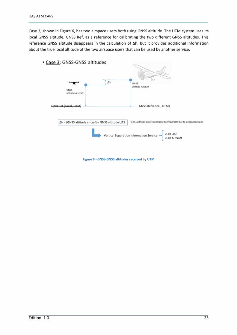
Case 3, shown in Figure 6, has two airspace users both using GNSS altitude. The UTM system uses its
local GNSS altitude, GNSS Ref, as a reference for calibrating the two different GNSS altitudes. This
reference GNSS altitude disappears in the calculation of Δh, but it provides additional information
about the true local altitude of the two airspace users that can be used by another service.
Figure 6 - GNSS-GNSS altitudes received by UTM

U-Space Services Implementation Monitoring Report
Edition 1.2 26
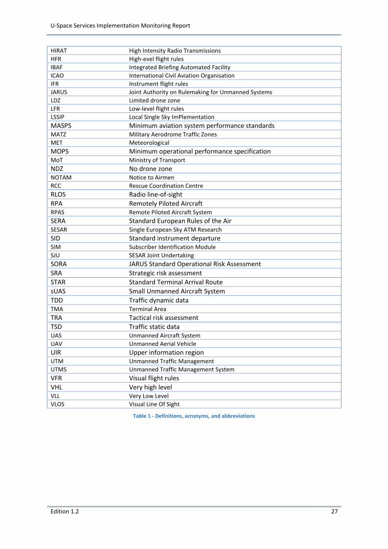
DEFINITIONS, ACRONYMS AND ABBREVIATIONS
Term Definition
ACAS Airborne Collision Avoidance System
ADS-B Automatic Dependent Surveillance-Broadcast
AFUA Advanced Flexible Use of Airspace
AGL Above Ground Level
AIM Aeronautical Information Management
AIRAC Aeronautical Information Regulation And Control
AIS Aeronautical Information Service
AMC Airspace Management Cell
ANS Air Navigation Service
ANSP Air Navigation Service Provider
ASBU Aviation Systems Block Upgrades
ATC Air Traffic Control
ATCO Air Traffic Control Officer
ATM Air Traffic Management
ATZ Aerodrome Traffic Zone
BRLOS Beyond Radio Line of Sight
BVLOS Beyond Visual Line of Sight
C2 Command and Control Link
CAA Civil Aviation Authority
CEF Connecting Europe Facility
CFR Code of Federal Regulations
CNS Communications, Navigation, Surveillance
COM Communications Technology
CONOPS Concept of Operations
CPDLC Controller Pilot Datalink Communication
CTR Control Zone
D&A / DAA Detect and Avoid
DTM Drone Traffic Management
EAD European Aviation Database
EASA European Aviation Safety Agency
EC European Commission
ECAC European Civil Aviation Conference
EDZ Exclusive drone zone
EOC Essential Operational Change
eIDAS electronic Identification and Trust Services
EU European Union
EVLOS Extended Visual Line Of Sight
FCC Flight Control Computer
FIS Flight Information Service
FL Flight Level
FLARM Flight Alarm
FOC Full Operational Capability
FPL Flight Plan
FUA Flexible Use of Airspace
GA General Aviation
GANP Global Air Navigation Plan
GIS Geographic Information System
GRA Generic risk assessment
HALE High-altitude long endurance
U-Space Services Implementation Monitoring Report
Edition 1.2 27
HIRAT High Intensity Radio Transmissions
HFR High-evel flight rules
IBAF Integrated Briefing Automated Facility
ICAO International Civil Aviation Organisation
IFR Instrument flight rules
JARUS Joint Authority on Rulemaking for Unmanned Systems
LDZ Limited drone zone
LFR Low-level flight rules
LSSIP Local Single Sky ImPlementation
MASPS Minimum aviation system performance standards
MATZ Military Aerodrome Traffic Zones
MET Meteorological
MOPS Minimum operational performance specification
MoT Ministry of Transport
NDZ No drone zone
NOTAM Notice to Airmen
RCC Rescue Coordination Centre
RLOS Radio line-of-sight
RPA Remotely Piloted Aircraft
RPAS Remote Piloted Aircraft System
SERA Standard European Rules of the Air
SESAR Single European Sky ATM Research
SID Standard instrument departure
SIM Subscriber Identification Module
SJU SESAR Joint Undertaking
SORA JARUS Standard Operational Risk Assessment
SRA Strategic risk assessment
STAR Standard Terminal Arrival Route
sUAS Small Unmanned Aircraft System
TDD Traffic dynamic data
TMA Terminal Area
TRA Tactical risk assessment
TSD Traffic static data
UAS Unmanned Aircraft System
UAV Unmanned Aerial Vehicle
UIR Upper information region
UTM Unmanned Traffic Management
UTMS Unmanned Traffic Management System
VFR Visual flight rules
VHL Very high level VLL Very Low Level
VLOS Visual Line Of Sight
Table 1 - Definitions, acronyms, and abbreviations