tyco electronics corporation soft shell pin and …
TRANSCRIPT
Catalog 82181Revised 2-03
Soft Shell Pin and Socket Connectors
Soft Shell Pin and Socket ConnectorsCatalog 82181 Revised 2-03
TYCO ELECTRONICS CORPORATION

Soft ShellPin and Socket Connectors
Catalog 82181Revised 2-03
2
Table of Contents
Dimensions are in inches and Dimensions are shown for Technical Support – Refer www.tycoelectronics.commillimeters unless otherwise reference purposes only. to inside back cover.specified. Values in brackets Specifications subjectare metric equivalents. to change.
Universal MATE-N-LOK II Connectors.......................................4-17Product Facts...............................................................................................................4Performance Characteristics ....................................................................................4, 5Mating Combinations ..................................................................................................6Contacts ...................................................................................................................7Housing Kits: Free Hanging or Panel Mount............................................................8, 9
Housing Components: Free Hanging or Panel Mount...............................10Plug or Cap Housing Strain Reliefs and Keying Plug................................11
Headers, PC Board: Vertical Pin ................................................................................12Vertical Socket ..........................................................................................13Recommended PC Board Hole Layouts ....................................................14PC Board Vertical Pin Headers with ACTION PIN Contacts.......................14Right-Angle Pin and Socket ......................................................................15
High Current Contacts ...............................................................................................16High Current Vertical Pin Headers .............................................................................17
Universal MATE-N-LOK Connectors........................................18-32Product Facts.............................................................................................................18Performance Characteristics ................................................................................18, 19Mating Combinations ................................................................................................20Contacts ...........................................................................................................21, 22Housings: Free Hanging or Panel Mount ...................................................................23
Cap Housing Panel Cutouts, Keying Plugs andPlug Housing Strain Reliefs ....................................................................24
Plug or Cap Housing Strain Reliefs and Cap Housing Adapters ...............25Flanged Cap Housings with Twist and Lock Feature .................................26
Splash-Proof Seals ....................................................................................................27Contacts (used with Splash-Proof Seals)...................................................................28Headers, PC Board: Vertical Pin ................................................................................29
Vertical Socket ..........................................................................................30Recommended PC Board Hole Layouts ....................................................31PC Board Vertical Pin Headers with ACTION PIN Contacts.......................31Right-Angle Pin and Socket ......................................................................32
Test Connectors.........................................................................................................32
Commercial MATE-N-LOK Connectors ....................................33-47Product Facts.............................................................................................................33Performance Characteristics ................................................................................33, 34Mating Combinations ..........................................................................................35, 36Contacts, Commoning Tabs and Keying Plug......................................................37, 38Housings: Free Hanging ......................................................................................39, 40
Positive Lock ............................................................................................40Panel Mount .............................................................................................41Flange Mount and Motor Mount ...............................................................42
Headers, PC Board: Vertical Pin ................................................................................43Surface Mount Right-Angle Pin and Vertical Socket .................................44Right-Angle Pin ........................................................................................45
Insulation Displacement Connectors (IDC) and Dust Covers.....................................45Edge Mount and Right-Angle Mid Mount Headers ....................................................46Right-Angle Pin Headers with Fix Belt .......................................................................47
.156 MATE-N-LOK Connectors .............................................48, 49Product Facts.............................................................................................................48Contacts .................................................................................................................48Housings: Free Hanging ............................................................................................49
Panel Mount .............................................................................................49
.140 MATE-N-LOK Connectors..............................................50-52Product Facts.............................................................................................................50Performance Characteristics ......................................................................................50Contacts .................................................................................................................51Housings: Free Hanging ............................................................................................51
Panel Mount .............................................................................................52
Introduction
AMP Soft Shell Pin andSocket connectors provide ahighly reliable and economicmeans of grouping multiple-lead connections in today’scomputer, computer/periph-eral equipment, business machines, entertainment centers, appliances and othersophisticated commercialequipment. The electricalconnector is an integral com-ponent in these applications.They also offer worldwidea pplication approval becauseof their reliability and econ-omy. Electrical functionshave increased in complexityand new designs continuallycall for the maximum use ofspace. The Soft Shell Pin andSocket family of connectorsoffers the design and featuresto answer these modern industry requirements.Included in this family ofSoft Shell Pin and SocketConnectors are: Universal MATE-N-LOK II,Universal MATE-N-LOK,Commercial MATE-N-LOK,.156 MATE-N-LOK, .140MATE-N-LOK, .093 [2.36]Commercial Pin and Socket,Mini-Universal MATE-N-LOK 2,Mini-Universal MATE-N-LOK,(MR) Miniature Rectangularand .062 [1.57] CommercialPin and Socket.This catalog is organized toprovide you with the basicinformation necessary to se-lect the Soft Shell connectorsystem best suited for yourspecific application. It con-tains general information toacquaint you with the com-plete family of connectorsand application tooling.Since your specific applica-tion will determine the degreeof automatic, semiautomaticor manual application toolingrequired, complete specifica-tions are covered on pages1 2 7 - 1 3 2 .
©1977-1980, 1983, 1986, 1988, 1992,1993, 1994, 1995, 1997, 1998, 2001 and2003 by Tyco Electronics Corporation. All Rights Reserved.

Dimensions are in inches and Dimensions are shown for Technical Support – Refer www.tycoelectronics.commillimeters unless otherwise reference purposes only. to inside back cover.specified. Values in brackets Specifications subjectare metric equivalents. to change.
Soft ShellPin and Socket Connectors
Catalog 82181Revised 2-03
3
Table of Contents (Continued)
Need more information?
Call Technical Support at alocal number listed on theinside back cover.
Technical Support is staffedwith specialists well versedin AMP products.
Or, you can choose theAMP FAX service option atthe voice prompt.Information requested willbe faxed within a few min-utes. Information availableincludes:
■ Drawings (the drawingnumber is the part number)
■ Instruction Sheets
■ Product Specifications
■ Latest revisions of catalogpages
■ List of your closest distributors
■ Instructions on how to u s ethe AMP FAX service toyour best advantage
■ Soft Shell Video US #198143 PAL #199610
Dimensioning:Dimensions are in inches and millimeters.Charts are inches over millimeters.Metric symbols used are:
m (meter)mm2 (square millimeter)cm (centimeter)N (newton)kg (kilogram)C (Celsius)m3/s (meter3/second)
Produced under a QualityManagement System certified to ISO 9001
ACTION PIN, AMP, AMP-DUAC, AMP FAX, AMP-O-LECTRIC, AMPOMATOR, AMP-O-MATIC, CERTI-CRIMP, FASTON, MATE-N-LOK,PRO-CRIMPER and TYCO are trademarks.Kapton is a trademark of E.I. du Pont deNemours and Company.
.093 [2.36] Commercial Pin and Socket Connectors ....................53-59Product Facts .............................................................................................................53Performance Characteristics.................................................................................53, 54Contacts ..................................................................................................................55Housings: Free Hanging or Panel Mount ..............................................................56-59
Micro MATE-N-LOK 3 mm Connector System ............................60-89Product Facts .............................................................................................................60Performance Characteristics.................................................................................60, 61Connector Application ..........................................................................................62-64Contacts ..................................................................................................................65Receptacle Housings............................................................................................66, 67Plug Housings......................................................................................................68-71Vertical Header Assemblies ..................................................................................72-79Right-Angle Header Assemblies ...........................................................................80-89
Mini-Universal MATE-N-LOK 2 Connectors ...............................90-98Product Facts .............................................................................................................90Performance Characteristics.................................................................................90, 91Contacts and Keying Plug ....................................................................................91, 92Housings: Free Hanging.......................................................................................92, 93Headers, PC Board: Vertical Pin and Blindmate ...................................................94, 95
Right-Angle Pin.........................................................................................96Recommended PC Board Hole Layouts .....................................................97
Mating Combinations.................................................................................................98
Mini-Universal MATE-N-LOK Connectors ................................99-110Product Facts .............................................................................................................99Performance Characteristics...............................................................................99, 100Mating Combinations...............................................................................................101Contacts, Keying Plug, Wire Seal and Test Probe Contact .......................................102Splash-Proof Seals ..........................................................................................103, 104Housings: Free Hanging or Panel Mount .........................................................103, 104
Hermaphroditic Free Hanging .................................................................105Headers, PC Board: Vertical Pin and Blindmate ...............................................106, 107
Right-Angle Pin.......................................................................................108Recommended PC Board Hole Layouts ...................................................109
Plug or Cap Housing Strain Reliefs ..........................................................................110
(MR) Miniature Rectangular Connectors ...............................111-120Product Facts ...........................................................................................................111Performance Characteristics.............................................................................111, 112Mating Combinations...............................................................................................113Contacts and Keying Plug ........................................................................................114Housings: Free Hanging or Panel Mount .........................................................115, 116
Recommended Panel Cutouts .................................................................117Strain Reliefs, Adapting Grommets and Commoning Bars ......................118
Headers, PC Board: Vertical Pin.......................................................................119, 120Recommended PC Board Hole Layouts ...........................................119, 120
.062 [1.57] Commercial Pin and Socket Connectors .................121-125Product Facts ...........................................................................................................121Performance Characteristics.............................................................................121, 122Contacts ................................................................................................................123Housings: Free Hanging or Panel Mount .........................................................124, 125
Recommended Panel Cutouts .................................................................125
Technical Documents...............................................................................................126Application Tooling ..........................................................................................127-130Applicator Options ...........................................................................................131, 132Part Number Index............................................................................................133-137MATE-N-LOK Product Feature Comparisons ...........................................................138

Dimensions are in inches and Dimensions are shown for Technical Support – Refer www.tycoelectronics.commillimeters unless otherwise reference purposes only. to inside back cover.specified. Values in brackets Specifications subjectare metric equivalents. to change.
Soft ShellPin and Socket Connectors
Catalog 82181Revised 2-03
4
Universal MATE-N-LOK II Connectors
Performance CharacteristicsThe Universal MATE-N-LOK IIConnector performance characteristicsfound on pages 4 and 5 are based onfree hanging and panel mountconnectors, loaded with contactscrimped on stranded wire.
Dielectric Withstanding Voltage5.0 KV AC or DC between adjacentcircuits initially
Insulation Resistance1000 megohms minimum between adjacent circuits
Voltage Rating 600 V AC or DC
Connector MatingSplit Pin — 1.5 lb. max. per circuit
Connector UnmatingSplit Pin — .5 lb. min. per circuit
Contact Insertion Force 3.0 lb. max.per contact unassembled
Contact Retention 35 lb. min. percontact
Durability 50 cycles, mating and unmating
Product Facts■ Ultimate reliability
■ For use where repair or re-placement would be difficult
■ Pins and sockets can be intermixed in the sameh o u s i n g
■ Available in 2 thru 15 circuitsizes for free hanging orpanel mount wire-to-wirec o n n e c t i o n
■ Mate with standardUniversal MATE-N-LOKHousings and PC BoardH e a d e r s
■ Uses standard UniversalMATE-N-LOK panel cutoutsand strain reliefs
■ Polarized housings availablein UL94V-0 flammabilityrated material
■ Enclosed contacts for shockp r o t e c t i o n
■ F-Crimp terminals accept30-10 AWG [.05 -5.0 mm2]wire sizes
■ Contacts available in stripand loose form
■ Lanceless contacts for tangle-free handling
■ Insulation capability to .200[5.08] diameter
■ Connector design providesfor complete contact insertion
■ Three-point stabilization pre-cisely controls contact align-ment, minimizing stubbing
■ Tin or duplex gold platedc o n t a c t s
■ Contacts are on .250 [6.35]centerline spacing
■ Not for interrupting current
■ Recognized under theComponent Program of Underwriters LaboratoriesInc., File No. E28476
■ Certified by CanadianStandards Association,File No. LR 7189
■ Passed test by VDE undertheir Registration Number3980/Continuous Surveillance
Technical DocumentsProduct Specification108-1090 Universal MATE-N-LOK II
ConnectorsApplication Specification114-1043 Universal MATE-N-LOK II
ContactsInstruction Sheet408-3200 Housing, Contacts and
Accessories

Dimensions are in inches and Dimensions are shown for Technical Support – Refer www.tycoelectronics.commillimeters unless otherwise reference purposes only. to inside back cover.specified. Values in brackets Specifications subjectare metric equivalents. to change.
Soft ShellPin and Socket Connectors
Catalog 82181Revised 2-03
5
Universal MATE-N-LOK II Connectors (Continued)
PerformanceCharacteristics (Continued)
Maximum Current Maximum currentrating of Universal MATE-N-LOK IIconnectors is limited by the maximumoperating temperature of the housingswhich is 120°C including thetemperature rise of the contacts which isa maximum of 30°C. There are severalvariables which have a direct effect onthis maximum current-carryingcapability for a given connector andmust be considered for each application.These variables are:
Wire Size Larger diameter wire willcarry more current since it has lessinternal resistance to current flow andthus generates less heat. Longer wirelengths also enhance current carryingcapabilities since the wire conducts heataway from the connector.
Connector Size In general, the morecircuits in a connector, the less currentcan be carried.
Ambient Temperature The higherthe ambient temperature, the less currentcan be carried in any given connector.
Universal MATE-N-LOK II connectorsalso will withstand the following tests:
Vibration 10-55-10 cycles per minuteat .06 inch total excursion
Physical Shock 18 drops, 50 gsawtooth at 10 milliseconds
Housing Panel Retention 75 lb. min.
Housing Lock Strength 35 lb. min.
Thermal Shock 255°C to 185°C
Temperature-Humidity Cycling25°C to 65°C at 95 RH
Corrosion 48 hr. at 5% salt concentration
Related Product DataProduct Specification108-1090 Universal MATE-N-LOK II
Connectors
Termination ContactResistance Crimp
Wire SizeTest Resistance
Tensile ForceAWG mm2
Current Milliohms Force (Min.)(Amps) (Max. Init.) lbs. N
30 .05 — — 1.5 728 .08 — — 3 1326 .12 — — 5 2224 .2 1.5 3.50 7 3122 .3 3 3.50 12 5320 .5 4.5 3.00 17 6618 .8 6 3.00 30 13316 1.2 8 2.75 45 20014 2.0 10 2.75 50 22212 3.0 — — 60 26710 5.0 — — 70 311
N o t e : This is the total resistance between wire crimps of a mated pin and socket.
Current Rating Verification for 308C Maximum Temperature Rise 100% Energized
Wire-to-Wire
Minimum Wire Lengths for T-Rise vs. Current TestingAWG Min. Length (in.) AWG Min. Length (in.)30 2.6 18 9.428 3.2 16 11.326 4.1 14 13.724 5.1 12 16.420 7.8 10 19.3
Note: If wire lengths used are less than those listed above, the currentcarrying ability of the system will be reduced due to less heat beingconducted away from the connector. The customer should fully test allapplications.
Calculated Current TableNumber of Wire Gauge
Circuits 10 12 14 16 18 20 22 24 26 302 19.00 18.00 17.00 14.50 13.00 10.00 8.00 6.50 5.50 3.503 17.50 16.50 15.50 13.00 12.00 9.00 7.50 6.00 5.00 3.004 16.50 15.50 15.00 12.50 11.00 8.50 7.00 5.50 4.50 3.005 16.00 15.00 14.00 12.00 10.50 8.00 6.50 5.50 4.50 3.00
6 Matrix 15.00 14.00 13.00 11.00 9.50 7.50 6.00 5.00 4.00 2.508 14.50 14.00 13.00 10.50 9.50 7.50 6.00 5.00 4.00 2.509 13.50 12.50 11.50 9.50 8.50 6.50 5.50 4.50 3.50 2.00
10 14.00 13.00 12.50 10.00 9.00 7.00 5.50 4.50 3.50 2.5012 12.50 12.00 11.00 9.00 8.00 6.00 5.00 4.00 3.00 2.0015 12.00 11.50 10.00 8.50 7.50 6.00 4.50 4.00 3.00 2.00
Values are based on initial Temperature Rise versus Current Testing and are intended to be a guide in the selectionof a connector family. All applications should be tested by the end user. The values listed are per circuit for fullyloaded housings being 100% energized. Note: All combinations were not tested, and this chart contains interpolatedand extrapolated values.
Wire-to-BoardDue to the vast differences in trace geometry and printed circuit board configurations, we are unable to provide a separate current carrying chart for our printed circuit board header products. However, the above Wire-to-Wire chartsmay be used as a guideline for headers if the trace width and thickness is equal to the listed wire gauge. For verticalheaders, only 95% of the Wire-to-Wire value should be used. For right-angle headers, only 75% of the Wire-to-Wirevalue should be used. The chart values are only a tool for connector selection and will require the customer to fullytest their application.
Termination Resistance/Contact Crimp Tensile Force
Dimensions are in inches and Dimensions are shown for Technical Support – Refer www.tycoelectronics.commillimeters unless otherwise reference purposes only. to inside back cover.specified. Values in brackets Specifications subjectare metric equivalents. to change.
Soft ShellPin and Socket Connectors
Catalog 82181Revised 2-03
6
Universal MATE-N-LOK II Connectors (Continued)
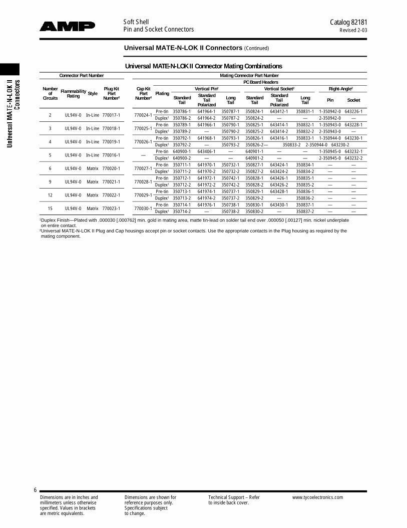
Universal MATE-N-LOK II Connector Mating CombinationsConnector Part Number Mating Connector Part Number
PC Board HeadersNumber Flammability Plug Kit Cap Kit Vertical Pin2 Vertical Socket2 Right-Angle2
of Style Part Part PlatingStandard Standard Long Standard Standard Long Pin SocketCircuits Rating Number2 Number2
Tail TailTail Polarized Tail Tail Polarized Tail
2 UL94V-0 In-Line 770017-1 770024-1Pre-tin 350786-1 641964-1 350787-1 350824-1 643412-1 350831-1 1-350942-0 643226-1Duplex1 350786-2 641964-2 350787-2 350824-2 — — 2-350942-0 —
3 UL94V-0 In-Line 770018-1 770025-1Pre-tin 350789-1 641966-1 350790-1 350825-1 643414-1 350832-1 1-350943-0 643228-1Duplex1 350789-2 — 350790-2 350825-2 643414-2 350832-2 2-350943-0 —
4 UL94V-0 In-Line 770019-1 770026-1Pre-tin 350792-1 641968-1 350793-1 350826-1 643416-1 350833-1 1-350944-0 643230-1Duplex1 350792-2 — 350793-2 350826-2 — 350833-2 2-350944-0 643230-2
5 UL94V-0 In-Line 770016-1 —Pre-tin 640900-1 643406-1 — 640901-1 — — 1-350945-0 643232-1Duplex1 640900-2 — — 640901-2 — — 2-350945-0 643232-2
6 UL94V-0 Matrix 770020-1 770027-1Pre-tin 350711-1 641970-1 350732-1 350827-1 643424-1 350834-1 — —Duplex1 350711-2 641970-2 350732-2 350827-2 643424-2 350834-2 — —
9 UL94V-0 Matrix 770021-1 770028-1Pre-tin 350712-1 641972-1 350742-1 350828-1 643426-1 350835-1 — —Duplex1 350712-2 641972-2 350742-2 350828-2 643426-2 350835-2 — —
12 UL94V-0 Matrix 770022-1 770029-1Pre-tin 350713-1 641974-1 350737-1 350829-1 643428-1 350836-1 — —Duplex1 350713-2 641974-2 350737-2 350829-2 — 350836-2 — —
15 UL94V-0 Matrix 770023-1 770030-1Pre-tin 350714-1 641976-1 350738-1 350830-1 643430-1 350837-1 — —Duplex1 350714-2 — 350738-2 350830-2 — 350837-2 — —
1Duplex Finish—Plated with .000030 [.000762] min. gold in mating area, matte tin-lead on solder tail end over .000050 [.00127] min. nickel underplate on entire contact.
2Universal MATE-N-LOK II Plug and Cap housings accept pin or socket contacts. Use the appropriate contacts in the Plug housing as required by the mating component.
Dimensions are in inches and Dimensions are shown for Technical Support – Refer www.tycoelectronics.commillimeters unless otherwise reference purposes only. to inside back cover.specified. Values in brackets Specifications subjectare metric equivalents. to change.
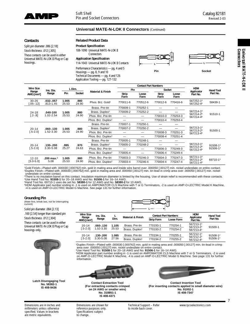
ContactsSplit pin diameter .086 [2.18]Stock thickness .012 [.305]These contacts can be used in eitherUniversal MATE-N-LOK II Plug or Caphousings.
Related Product DataProduct Specification108-1090 Universal MATE-N-LOK II
ConnectorsApplication Specification114-1043 Universal MATE-N-LOK II Contacts
Performance Characteristics— pg. 4 and 5Housings — pg. 8, 9 and 10Technical Documents — pg. 4 and 126Application Tooling — pg. 127-132
Contact Extraction Tool(For extracting contacts crimped
on 24 AWG or smaller wire)No. 318851-1IS 408-4371
Latch Disengaging ToolNo. 58382-1IS 408-9436
Contact Insertion Tool(For inserting contacts applied to small diameter wire)
No. 91002-1IS 408-7347
Pin Socket
Grounding Pin(Mate first, break last, not for interruptingcurrent)
Solid pin diameter .084 [2.13].100 [2.54] longer than standard pinStock thickness .012 [.304]These contacts can be used in eitherUniversal MATE-N-LOK II Plug or Caphousings only.
L L
L
Contact Part NumbersWire Size
Ins. Dia. L Dim. Pin Socket HDMHand ToolRange
Range Pin Socket Material & FinishStrip Loose Strip Loose
ApplicatorPart No.AWG [mm2]
Form Form Form FormPart No.
30-26 .032-.057 1.005 .980 Phos. Brz. Gold1 770011-6 770512-6 770012-6 770416-6 567252-1658439-1[.05-.12] .813-1.45 25.53 24.90 567252-46
Brass. Pre-tin 770009-1 770252-1 — —
24-18 .040-100 1.005 .980 Brass. Duplex2 770009-2 770252-2 — — 567214-16
91510-1[.2-.8] 1.02-2.54 25.53 24.90 Phos. Brz. Pre-tin — — 770010-3 770253-3567214-26
Phos. Brz. Duplex2 — — 770010-4 770253-4567214-46
Brass. Pre-tin 770007-1 770250-1 — —
20-14 .060-.130 1.005 .980 Brass. Duplex2 770007-2 770250-2 — — 567213-16
91500-1[.5-2.0] 1.52-3.30 25.53 24.90 Phos. Brz. Pre-tin — — 770008-3 770251-3567213-26
Phos. Brz. Duplex2 — — 770008-4 770251-4567213-46
Brass. Pre-tin 770005-1 770248-1 — —
20-14 .130-.200 .995 .970 Brass. Duplex2 770005-2 770248-2 — — 567212-1691508-14
[.5-2.0] 3.30-5.08 25.27 24.63 Phos. Brz. Pre-tin — — 770006-3 770249-3567212-26
9 1 5 0 6 - 14
Phos. Brz. Duplex2 770005-4 — 770006-4 770249-4567212-46
12-10 .200 max.3 1.005 .980 Phos. Brz. Pre-tin 770003-3 770246-3 770004-3 770247-3 567211-16
567211-26 69710-15[3.0-5.0] 5.08 25.53 24.90 Phos. Brz. Duplex2 770003-4 770246-4 770004-4 770247-4 567211-46
1Gold Finish—Plated with .000030 [.000762] min. gold in mating area and inside wire barrel over .000050 [.00127] min. nickel underplate on entire contact.2Duplex Finish—Plated with .000030 [.000762] min. gold in mating area and .000050 [.00127] min. tin-lead in crimp area over .000050 [.00127] min. nickel underplate on entire contact.
3There is no insulation barrel on this contact. Insulation maximum diameter is limited by the housing. Use of strain relief is recommended with these contacts.4Use Hand Tool No. 91508-1 for 20–18 AWG and No. 91506-1 for 16–14 AWG.5Hand Tool No. 69710-1 uses die set No. 58380-1 for 12 AWG and No. 58380-2 for 10 AWG.6HDM Applicator part number ending in -1 is used on AMPOMATOR CLS Machine with T or G Terminators, -2 is used on AMP-O-LECTRIC Model K Machine,-4 is used on AMP-O-LECTRIC Model G Machine. See page 131 for further information.
Wire Size Ins. Dia. L Contact Part Numbers HDM Hand ToolRange Material & Finish ApplicatorAWG [mm2] Range Dim. Strip Form Loose Form Part No. Part No.
20-14 .060-.130 1.105 Brass. Pre-tin 770193-1 770254-1 567213-13
567213-23 91500-1[.5-2.0] 1.52-3.30 25.53 Brass. Duplex1 770193-2 770254-2 567213-43
20-14 .130-.200 1.085 Brass. Pre-tin 770194-1 770255-1 567212-1391508-12
567212-2391506-12[.5-2.0] 3.30-5.08 27.56 Brass. Duplex1 770194-2 770255-2 567212-43
1Duplex Finish—Plated with .000030 [.000762] min. gold in mating area and .000050 [.00127] min. tin-lead in crimparea over .000050 [.00127] min. nickel underplate on entire contact.
2Use Hand Tool No. 91508-1 for 20–18 AWG and No. 91506-1 for 16–14 AWG.3HDM Applicator part number ending in -1 is used on AMPOMATOR CLS Machine with T or G Terminators, -2 is usedon AMP-O-LECTRIC Model K Machine, -4 is used on AMP-O-LECTRIC Model G Machine. See page 131 for furtherinformation.
Soft ShellPin and Socket Connectors
Catalog 82181Revised 2-03
7
Universal MATE-N-LOK II Connectors (Continued)
Dimensions are in inches and Dimensions are shown for Technical Support – Refer www.tycoelectronics.commillimeters unless otherwise reference purposes only. to inside back cover.specified. Values in brackets Specifications subjectare metric equivalents. to change.
Soft ShellPin and Socket Connectors
Catalog 82181Revised 2-03
8
Universal MATE-N-LOK II Connectors (Continued)
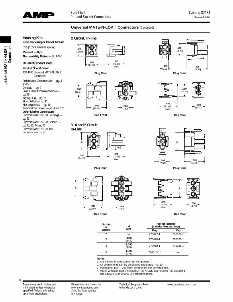
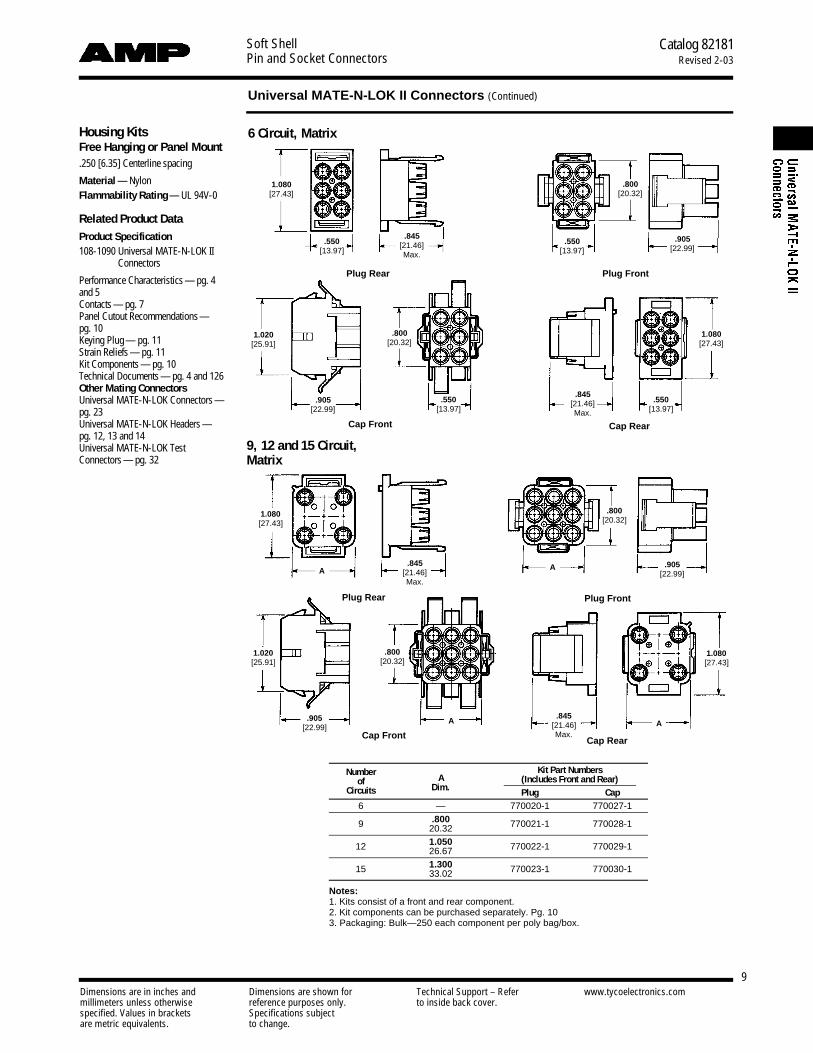
Housing KitsFree Hanging or Panel Mount.250 [6.35] Centerline spacing
Material — NylonFlammability Rating — UL 94V-0
Related Product DataProduct Specification108-1090 Universal MATE-N-LOK II
Connectors
Performance Characteristics — pg. 4and 5Contacts — pg. 7Panel Cutout Recommendations—pg. 10Keying Plug — pg. 11Strain Reliefs — pg. 11Kit Components — pg. 10Technical Documents — pg. 4 and 126Other Mating ConnectorsUniversal MATE-N-LOK Housings —pg. 23Universal MATE-N-LOK Headers —pg. 12, 13, 14 and 15Universal MATE-N-LOK TestConnectors — pg. 32
3, 4 and 5 Circuit,In-Line
Plug Rear
Cap Front
Cap Front
Plug Rear Plug Front
Cap Rear
Cap Rear
Plug Front
2 Circuit, In-line
.550[13.97]
.580[14.73]
.845[21.46]Max. .300
[7.62]
.550[13.97]
.550[13.97]
.905[22.98]
.580[14.73]
.845[21.46]Max.
.550[13.97]
.905[22.98]
. 3 0 0[ 7 . 6 2 ]
A
.580[14.73]
. 3 0 0[ 7 . 6 2 ]
A
.845[21.46]Max.
.905[22.98]
.845[21.46]Max.
.580[14.73]
A
A
. 3 0 0[ 7 . 6 2 ]
.905[22.98]
Number Kit Part Numbersof A (Includes Front and Rear)
Circuits Dim. Plug Cap2 — 770017-1 770024-1
3 .800 770018-1 770025-120.32
4 1.050 770019-1 770026-126.67
5 1.300 770016-14 —33.02
Notes:1. Kits consist of a front and rear component.2. Kit components can be purchased separately. Pg. 103. Packaging: Bulk—250 each component per poly bag/box.4. Mates with standard Universal MATE-N-LOK cap housing P/N 350810-1
and 640900-X or 640901-X Vertical headers.
Dimensions are in inches and Dimensions are shown for Technical Support – Refer www.tycoelectronics.commillimeters unless otherwise reference purposes only. to inside back cover.specified. Values in brackets Specifications subjectare metric equivalents. to change.
Soft ShellPin and Socket Connectors
Catalog 82181Revised 2-03
9
Universal MATE-N-LOK II Connectors (Continued)
Housing KitsFree Hanging or Panel Mount.250 [6.35] Centerline spacing
Material — NylonFlammability Rating — UL 94V-0
Related Product DataProduct Specification108-1090 Universal MATE-N-LOK II
Connectors
Performance Characteristics — pg. 4and 5Contacts — pg. 7Panel Cutout Recommendations—pg. 10Keying Plug — pg. 11Strain Reliefs — pg. 11Kit Components — pg. 10Technical Documents — pg. 4 and 126Other Mating ConnectorsUniversal MATE-N-LOK Connectors —pg. 23Universal MATE-N-LOK Headers —pg. 12, 13 and 14Universal MATE-N-LOK TestConnectors — pg. 32
9, 12 and 15 Circuit,Matrix
Plug Rear
Cap Front
Cap Front
Plug Rear Plug Front
Cap Rear
Cap Rear
Plug Front
6 Circuit, Matrix
1.080[27.43]
.845[21.46]Max.
.550[13.97]
.550[13.97]
.800[20.32]
.905[22.99]
1.020[25.91]
.905[22.99]
.800[20.32]
.550[13.97]
.845[21.46]Max.
.550[13.97]
1.080[27.43]
1.080[27.43]
1.020[25.91]
A
.905[22.99]
.845[21.46]Max.
.800[20.32]
A
A .905[22.99]
.800[20.32]
.845[21.46]Max.
A
1.080[27.43]
Number Kit Part Numbersof A (Includes Front and Rear)
Circuits Dim. Plug Cap6 — 770020-1 770027-1
9 .800 770021-1 770028-120.32
12 1.050 770022-1 770029-126.67
15 1.300 770023-1 770030-133.02
Notes:1. Kits consist of a front and rear component.2. Kit components can be purchased separately. Pg. 103. Packaging: Bulk—250 each component per poly bag/box.

Number Kit Component Part Numbersof Plug Cap
Circuits Kit Front Rear Kit Front Rear2 770017-1 770031-1 770032-1 770024-1 770045-1 770046-13 770018-1 770033-1 770034-1 770025-1 770047-1 770048-14 770019-1 770035-1 770036-1 770026-1 770049-1 770050-15 770016-1 770319-1 770320-1 — — —6 770020-1 770037-1 770038-1 770027-1 770051-1 770052-19 770021-1 770039-1 770040-1 770028-1 770053-1 770054-1
12 770022-1 770041-1 770042-1 770029-1 770055-1 770056-115 770023-1 770043-1 770044-1 770030-1 770057-1 770058-1
Notes:1. Kits consist of a front and rear component.2. Kit components can be purchased separately.
Dimensions are in inches and Dimensions are shown for Technical Support – Refer www.tycoelectronics.commillimeters unless otherwise reference purposes only. to inside back cover.specified. Values in brackets Specifications subjectare metric equivalents. to change.
Soft ShellPin and Socket Connectors
Catalog 82181Revised 2-03
10
Universal MATE-N-LOK II Connectors (Continued)
RecommendedCap HousingPanel Cutouts
View is from cap entry side
Refer to Application Specification114-1043
Notes:1. Recommended panel thickness—.030-.090 [.762-2.286]. Panel must be punched so that housing enters panel in
same direction as the punch.2. Optional—Do not remove this material when keying cap housing to panel.3. Circuit #1 location when using panel keying with 6, 9, 12 and 15 circuit housings.4. Circuit #1 location when using panel keying with 2, 3, and 4 circuit housings.
Number of DimensionsCircuits A B C D E
2 .565 .340 .095 .530 .25014.35 8.63 2.41 13.46 6.35
3 .815 .340 .095 .530 .25020.70 8.63 2.41 13.46 6.35
4 1.065 .340 .095 .530 .25027.05 8.63 2.41 13.46 6.35
6 .565 .480 .275 1.030 .25014.35 12.19 6.99 26.16 6.35
9 .815 .480 .275 1.030 .25020.70 12.19 6.99 26.16 6.35
12 1.065 .480 .275 1.030 .35027.05 12.19 6.99 26.16 8.89
15 1.315 .480 .275 1.030 .35033.40 12.19 6.99 26.16 8.89
Housing ComponentsFree Hanging or Panel Mount.250 [6.35] Centerline spacing
Material — NylonFlammability Rating — UL 94V-0
Related Product DataProduct Specification108-1090 Universal MATE-N-LOK II
Connectors
Performance Characteristics —pg. 4 and 5Contacts — pg. 7Illustrations and Dimensions — pg. 8and 9Panel Cutout Recommendations—pg. 10Keying Plug — pg. 11Strain Reliefs — pg. 11Technical Documents — pg. 4 and 126Other Mating ConnectorsUniversal MATE-N-LOK Connectors —pg. 23Universal MATE-N-LOK Headers —pg. 12, 13, 14 and 15Universal MATE-N-LOK TestConnectors — pg. 32
Cap HousingPlug Housing
Dimensions are in inches and Dimensions are shown for Technical Support – Refer www.tycoelectronics.commillimeters unless otherwise reference purposes only. to inside back cover.specified. Values in brackets Specifications subjectare metric equivalents. to change.
Soft ShellPin and Socket Connectors
Catalog 82181Revised 2-03
11
Universal MATE-N-LOK II Connectors (Continued)
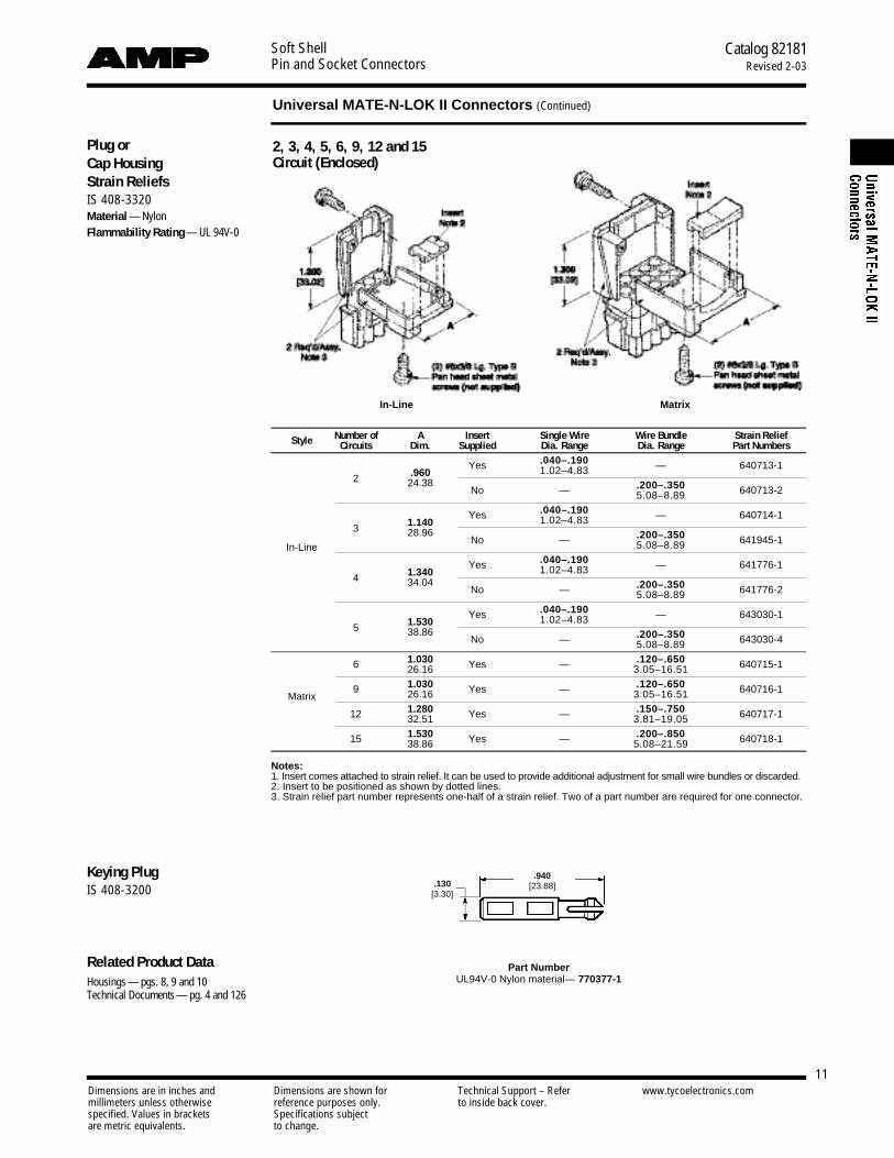
Plug orCap HousingStrain ReliefsIS 408-3320Material — NylonFlammability Rating — UL 94V-0
Keying PlugIS 408-3200
Related Product DataHousings — pgs. 8, 9 and 10Technical Documents — pg. 4 and 126
2, 3, 4, 5, 6, 9, 12 and 15Circuit (Enclosed)
.940[23.88].130
[3.30]
Style Number of A Insert Single Wire Wire Bundle Strain ReliefCircuits Dim. Supplied Dia. Range Dia. Range Part Numbers
Yes .040–.190 — 640713-12 .960 1.02–4.83
24.38No — .200–.350 640713-25.08–8.89
Yes .040–.190 — 640714-13 1.140 1.02–4.83
28.96No — .200–.350 641945-1
In-Line 5.08–8.89
Yes .040–.190 — 641776-14 1.340 1.02–4.83
34.04No — .200–.350 641776-25.08–8.89
Yes .040–.190 — 643030-15 1.530 1.02–4.83
38.86No — .200–.350 643030-45.08–8.89
6 1.030 Yes — .120–.650 640715-126.16 3.05–16.51
9 1.030 Yes — .120–.650 640716-1Matrix 26.16 3.05–16.51
12 1.280 Yes — .150–.750 640717-132.51 3.81–19.05
15 1.530 Yes — .200–.850 640718-138.86 5.08–21.59
Notes:1. Insert comes attached to strain relief. It can be used to provide additional adjustment for small wire bundles or discarded.2. Insert to be positioned as shown by dotted lines.3. Strain relief part number represents one-half of a strain relief. Two of a part number are required for one connector.
Part NumberUL94V-0 Nylon material— 770377-1
In-Line Matrix
Dimensions are in inches and Dimensions are shown for Technical Support – Refer www.tycoelectronics.commillimeters unless otherwise reference purposes only. to inside back cover.specified. Values in brackets Specifications subjectare metric equivalents. to change.
Soft ShellPin and Socket Connectors
Catalog 82181Revised 2-03
12
Universal MATE-N-LOK Headers for UMNL II Connectors
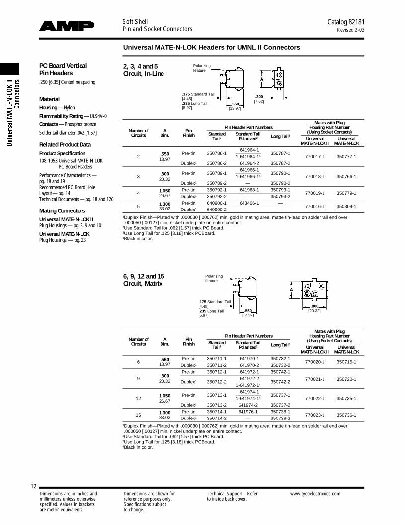
PC Board VerticalPin Headers.250 [6.35] Centerline spacing
MaterialHousing — Nylon
Flammability Rating — UL94V-0
Contacts — Phosphor bronze
Solder tail diameter .062 [1.57]
Related Product DataProduct Specification108-1053 Universal MATE-N-LOK
PC Board Headers
Performance Characteristics —pg. 18 and 19Recommended PC Board Hole Layout — pg. 14Technical Documents — pg. 18 and 126
Mating ConnectorsUniversal MATE-N-LOK IIPlug Housings— pg. 8, 9 and 10
Universal MATE-N-LOKPlug Housings — pg. 23
Mates with Plug
Number of A PinPin Header Part Numbers Housing Part Number
Circuits Dim. Finish Standard Standard Tail Long Tail3(Using Socket Contacts)
Tail2 Polarized2 Universal UniversalMATE-N-LOK II MATE-N-LOK
.550 Pre-tin 350786-11-641964-14
350787-12 13.97 1-641964-14 770017-1 350777-1
Duplex1 350786-2 1-641964-24 350787-2
.800 Pre-tin 350789-11-641966-14
350790-13 20.32 1-641966-14 770018-1 350766-1
Duplex1 350789-2 — 350790-2
4 1.050 Pre-tin 350792-1 1-641968-14 350793-1770019-1 350779-126.67 Duplex1 350792-2 — 350793-2
5 1.300 Pre-tin 640900-1 1-643406-14 —770016-1 350809-133.02 Duplex1 640900-2 — —
1Duplex Finish—Plated with .000030 [.000762] min. gold in mating area, matte tin-lead on solder tail end over.000050 [.00127] min. nickel underplate on entire contact.
2Use Standard Tail for .062 [1.57] thick PC Board.3Use Long Tail for .125 [3.18] thick PCBoard.4Black in color.
.175 Standard Tail[4.45].235 Long Tail[5.97]
.300[7.62]
.550[13.97]
.175 Standard Tail[4.45].235 Long Tail[5.97]
.800[20.32]
2, 3, 4 and 5Circuit, In-Line
6, 9, 12 and 15Circuit, Matrix
Polarizingfeature
Polarizingfeature
.550[13.97]
Mates with Plug
Number of A PinPin Header Part Numbers Housing Part Number
Circuits Dim. Finish Standard Standard Tail Long Tail3(Using Socket Contacts)
Tail2 Polarized2 Universal UniversalMATE-N-LOK II MATE-N-LOK
6 .550 Pre-tin 350711-1 1-641970-14 350732-1770020-1 350715-113.97 Duplex1 350711-2 1-641970-24 350732-2
.800Pre-tin 350712-1 1-641972-14 350742-1
9 20.32 Duplex1 350712-21-641972-24
350742-2 770021-1 350720-11-641972-14
1.050 Pre-tin 350713-11-641974-14
350737-112 26.67 1-641974-14 770022-1 350735-1
Duplex1 350713-2 641974-2 350737-2
15 1.300 Pre-tin 350714-1 641976-1 350738-1770023-1 350736-133.02 Duplex1 350714-2 — 350738-2
1Duplex Finish—Plated with .000030 [.000762] min. gold in mating area, matte tin-lead on solder tail end over.000050 [.00127] min. nickel underplate on entire contact.
2Use Standard Tail for .062 [1.57] thick PC Board.3Use Long Tail for .125 [3.18] thick PCBoard.4Black in color.

Dimensions are in inches and Dimensions are shown for Technical Support – Refer www.tycoelectronics.commillimeters unless otherwise reference purposes only. to inside back cover.specified. Values in brackets Specifications subjectare metric equivalents. to change.
Soft ShellPin and Socket Connectors
Catalog 82181Revised 2-03
13
Universal MATE-N-LOK Headers for UMNL II Connectors (Continued)
PC Board VerticalSocket Headers.250 [6.35] Centerline spacing
MaterialHousing — Nylon
Flammability Rating — UL94V-0
Contacts — Phosphor bronze
Solder tail diameter .062 [1.57]
Related Product DataProduct Specification108-1053 Universal MATE-N-LOK
PC Board Headers
Performance Characteristics —pg. 18 and 19Recommended PC Board Hole Layout —pg. 14Technical Documents — pg. 18 and 126
Mating ConnectorsUniversal MATE-N-LOK IIPlug Housings — pg. 8, 9 and 10
Universal MATE-N-LOKPlug Housings — pg. 23
2, 3, 4 and 5 Circuit, In-Line
6, 9, 12 and 15 Circuit, Matrix
.175 Standard Tail[4.45].235 Long Tail[5.97]
.300[7.62]
.550[13.97]
.175 Standard Tail[4.45].235 Long Tail[5.97]
.800[20.32]
Polarizingfeature
Polarizingfeature
.550[13.97]
Mates with Plug
Number of A SocketSocket Header Part Numbers Housing Part Number
Circuits Dim. Finish Standard Standard Tail Long Tail3(Using Pin Contacts)
Tail2 Polarized2 Universal UniversalMATE-N-LOK II MATE-N-LOK
2 .550 Pre-tin 350824-1 643412-1 350831-1770017-1 350777-113.97 Duplex1 350824-2 — —
3 .800 Pre-tin 350825-1 643414-1 350832-1770018-1 350766-120.32 Duplex1 350825-2 643414-2 350832-2
4 1.050 Pre-tin 350826-1 643416-1 350833-1770019-1 350779-126.67 Duplex1 350826-2 — 350833-2
5 1.300 Pre-tin 640901-1 — —770016-1 350809-133.02 Duplex1 640901-2 — —
1Duplex Finish—Plated with .000030 [.000762] min. gold in mating area, matte tin-lead on solder tail end over.000050 [.00127] min. nickel underplate on entire contact.
2Use Standard Tail for .062 [1.57] thick PC Board.3Use Long Tail for .125 [3.18] thick PCBoard.
Mates with Plug
Number of A SocketSocket Header Part Numbers Housing Part Number
Circuits Dim. Finish Standard Standard Tail Long Tail3(Using Pin Contacts)
Tail2 Polarized2 Universal UniversalMATE-N-LOK II MATE-N-LOK
6 .550 Pre-tin 350827-1 643424-1 350834-1770020-1 350715-113.97 Duplex1 350827-2 643424-2 350834-2
9 .800 Pre-tin 350828-1 643426-1 350835-1770021-1 350720-120.32 Duplex1 350828-2 643426-2 350835-2
12 1.050 Pre-tin 350829-1 643428-1 350836-1770022-1 350735-126.67 Duplex1 350829-2 — 350836-2
15 1.300 Pre-tin 350830-1 643430-1 350837-1770023-1 350736-133.02 Duplex1 350830-2 — 350837-2
1Duplex Finish—Plated with .000030 [.000762] min. gold in mating area, matte tin-lead on solder tail end over.000050 [.00127] min. nickel underplate on entire contact.
2Use Standard Tail for .062 [1.57] thick PC Board.3Use Long Tail for .125 [3.18] thick PCBoard.
Dimensions are in inches and Dimensions are shown for Technical Support – Refer www.tycoelectronics.commillimeters unless otherwise reference purposes only. to inside back cover.specified. Values in brackets Specifications subjectare metric equivalents. to change.
Soft ShellPin and Socket Connectors
Catalog 82181Revised 2-03
14
Universal MATE-N-LOK Headers for UMNL II Connectors (Continued)
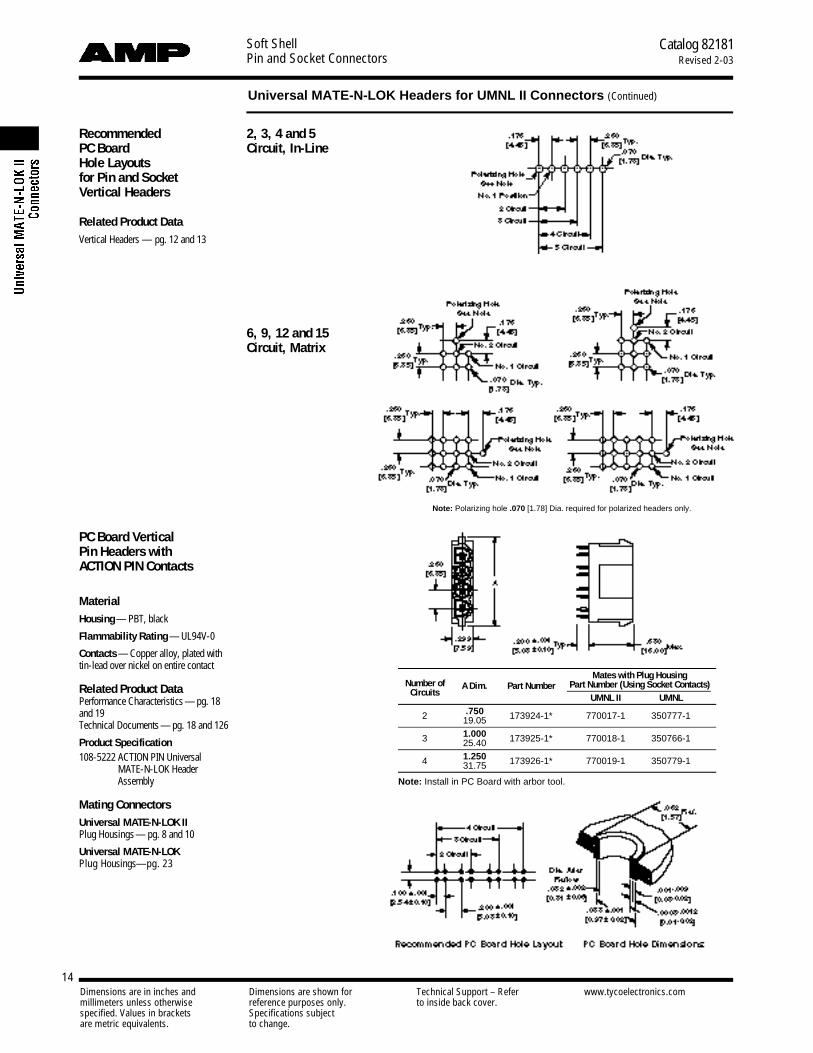
RecommendedPC BoardHole Layoutsfor Pin and SocketVertical Headers
Related Product DataVertical Headers — pg. 12 and 13
2, 3, 4 and 5Circuit, In-Line
6, 9, 12 and 15Circuit, Matrix
Note: Polarizing hole .070 [1.78] Dia. required for polarized headers only.
PC Board VerticalPin Headers withACTION PIN Contacts
MaterialHousing — PBT, black
Flammability Rating — UL94V-0
Contacts — Copper alloy, plated withtin-lead over nickel on entire contact
Related Product DataPerformance Characteristics — pg. 18and 19Technical Documents — pg. 18 and 126
Product Specification108-5222 ACTION PIN Universal
MATE-N-LOK HeaderAssembly
Mating ConnectorsUniversal MATE-N-LOK IIPlug Housings— pg. 8 and 10
Universal MATE-N-LOKPlug Housings—pg. 23
Number of Mates with Plug Housing
CircuitsA Dim. Part Number Part Number (Using Socket Contacts)
UMNL II UMNL
2 .750 173924-1* 770017-1 350777-119.05
3 1.000 173925-1* 770018-1 350766-125.40
4 1.250 173926-1* 770019-1 350779-131.75
Note: Install in PC Board with arbor tool.

Dimensions are in inches and Dimensions are shown for Technical Support – Refer www.tycoelectronics.commillimeters unless otherwise reference purposes only. to inside back cover.specified. Values in brackets Specifications subjectare metric equivalents. to change.
Soft ShellPin and Socket Connectors
Catalog 82181Revised 2-03
15
Universal MATE-N-LOK Headers for UMNL II Connectors (Continued)
PC Board Right-AnglePin and Socket Headers.250 [6.35] Centerline spacing
MaterialHousing — Nylon
Flammability Rating — UL 94V-0
Contacts — Phosphor bronzeSolder tail width .052 [1.32]
Related Product DataProduct Specification108-1053 Universal MATE-N-LOK
PC Board HeadersPerformance Characteristics — pg. 18and 19Technical Documents — pg. 18 and 126
Mating ConnectorsUniversal MATE-N-LOK IIPlug Housings— pg. 8 and 10
Universal MATE-N-LOKPlug Housings— pg. 23
Part NumbersNumber of Dimensions Contact Right-Angle Header Mates with Plug Housing
Circuits A B C FinishPin Socket Universal Universal
MATE-N-LOK II MATE-N-LOK
2 .550 1.245 .830 Pre-tin 1-350942-0 643226-1770017-1 350777-113.97 31.62 21.08 Duplex1 2-350942-0 —
3 .800 1.495 1.080 Pre-tin 1-350943-0 643228-1770018-1 350766-120.32 37.97 27.43 Duplex1 2-350943-0 643228-2
4 1.050 1.745 1.330 Pre-tin 1-350944-0 643230-1770019-1 350779-126.67 44.32 33.78 Duplex1 2-350944-0 643230-2
5 1.300 1.995 1.580 Pre-tin 1-350945-0 643232-1770016-1 350809-133.02 50.67 40.13 Duplex1 2-350945-0 643232-2
1Duplex Finish—Plated with .000030 [.000762] min. gold in mating area, matte tin-lead on solder tail end over.000050 [.00127] min. nickel underplate on entire contact.
.680[17.27]
.360[9.14]
.250[6.35]
.160[4.06]
Recommended PC Board Hole Layout.062 [1.57] Board Thickness
Typ.
2, 3, 4 and 5 Circuit, In-line
Use 6-32 UNC Pan Head Screw3/8 [9.53] long for mounting
(Not Supplied)
Dimensions are in inches and Dimensions are shown for Technical Support – Refer www.tycoelectronics.commillimeters unless otherwise reference purposes only. to inside back cover.specified. Values in brackets Specifications subjectare metric equivalents. to change.
Soft ShellPin and Socket Connectors
Catalog 82181Revised 2-03
16
Universal MATE-N-LOK II Connectors (Continued)
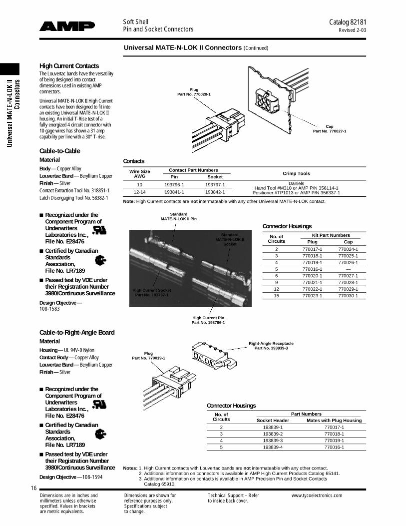
High Current ContactsThe Louvertac bands have the versatilityof being designed into contactdimensions used in existing AMPconnectors.
Universal MATE-N-LOK II High Currentcontacts have been designed to fit intoan existing Universal MATE-N-LOK IIhousing. An initial T-Rise test of a fully energized 4 circuit connector with10 gage wires has shown a 31 ampcapability per line with a 30° T-rise.
Cable-to-CableMaterialBody — Copper AlloyLouvertac Band — Beryllium CopperFinish — SilverContact Extraction Tool No. 318851-1Latch Disengaging Tool No. 58382-1
■ Recognized under theComponent Program ofUnderwriters Laboratories Inc., File No. E28476
■ Certified by CanadianStandards Association, File No. LR7189
■ Passed test by VDE undertheir Registration Number3980/Continuous Surveillance
Design Objective —108-1583
Contacts
Wire Size Contact Part NumbersCrimp ToolsAWG Pin Socket
10 193796-1 193797-1 DanielsHand Tool #M310 or AMP P/N 356114-1
12-14 193841-1 193842-1 Positioner #TP1013 or AMP P/N 356337-1
Note: High Current contacts are not intermateable with any other Universal MATE-N-LOK contact.
Connector Housings
No. of Kit Part NumbersCircuIts Plug Cap
2 770017-1 770024-13 770018-1 770025-14 770019-1 770026-15 770016-1 —6 770020-1 770027-19 770021-1 770028-1
12 770022-1 770029-115 770023-1 770030-1
Cable-to-Right-Angle BoardMaterialHousing — UL 94V-0 NylonContact Body — Copper AlloyLouvertac Band — Beryllium CopperFinish — Silver
■ Recognized under theComponent Program ofUnderwriters Laboratories Inc., File No. E28476
■ Certified by CanadianStandards Association, File No. LR7189
■ Passed test by VDE undertheir Registration Number3980/Continuous Surveillance
Design Objective —108-1594
Connector HousingsNo. of Part Numbers
CircuIts Socket Header Mates with Plug Housing2 193839-1 770017-13 193839-2 770018-14 193839-3 770019-15 193839-4 770016-1
Notes: 1. High Current contacts with Louvertac bands are not intermateable with any other contact.2. Additional information on connectors is available in AMP High Current Products Catalog 65141.3. Additional information on contacts is available in AMP Precision Pin and Socket Contacts
Catalog 65910.
Standard MATE-N-LOK II Pin
Standard MATE-N-LOK II
Socket
High Current SocketPart No. 193797-1
High Current Pin Part No. 193796-1
PlugPart No. 770020-1
CapPart No. 770027-1
PlugPart No. 770019-1
Right-Angle ReceptaclePart No. 193839-3
Dimensions are in inches and Dimensions are shown for Technical Support – Refer www.tycoelectronics.commillimeters unless otherwise reference purposes only. to inside back cover.specified. Values in brackets Specifications subjectare metric equivalents. to change.
Soft ShellPin and Socket Connectors
Catalog 82181Revised 2-03
17
Universal MATE-N-LOK II Connectors (Continued)
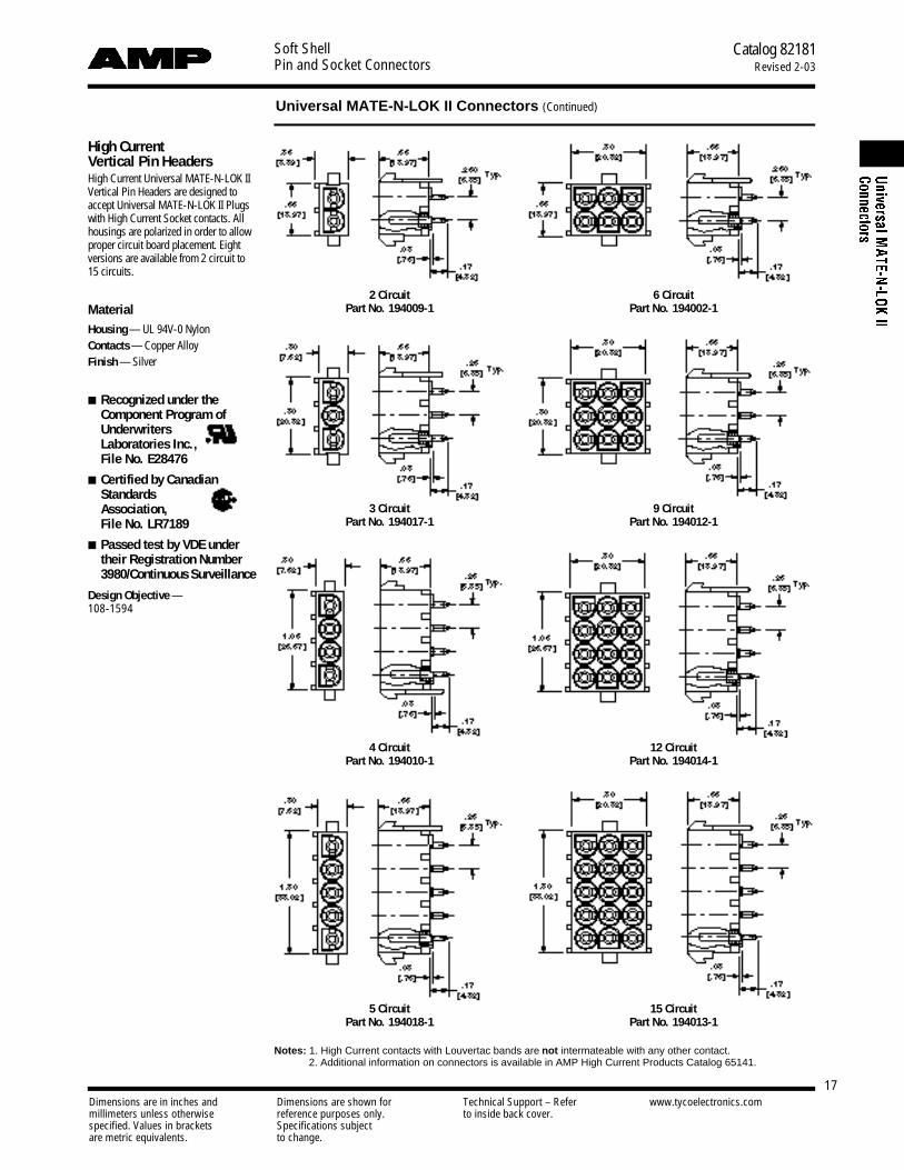
15 CircuitPart No. 194013-1
High Current Vertical Pin HeadersHigh Current Universal MATE-N-LOK IIVertical Pin Headers are designed toaccept Universal MATE-N-LOK II Plugswith High Current Socket contacts. Allhousings are polarized in order to allowproper circuit board placement. Eightversions are available from 2 circuit to15 circuits.
MaterialHousing — UL 94V-0 NylonContacts — Copper AlloyFinish — Silver
■ Recognized under theComponent Program ofUnderwriters Laboratories Inc., File No. E28476
■ Certified by CanadianStandards Association, File No. LR7189
■ Passed test by VDE undertheir Registration Number3980/Continuous Surveillance
Design Objective —108-1594
Notes: 1. High Current contacts with Louvertac bands are not intermateable with any other contact.2. Additional information on connectors is available in AMP High Current Products Catalog 65141.
2 CircuitPart No. 194009-1
6 CircuitPart No. 194002-1
3 CircuitPart No. 194017-1
9 CircuitPart No. 194012-1
4 CircuitPart No. 194010-1
12 CircuitPart No. 194014-1
5 CircuitPart No. 194018-1

Dimensions are in inches and Dimensions are shown for Technical Support – Refer www.tycoelectronics.commillimeters unless otherwise reference purposes only. to inside back cover.specified. Values in brackets Specifications subjectare metric equivalents. to change.
Soft ShellPin and Socket Connectors
Catalog 82181Revised 2-03
18
Performance CharacteristicsThe Universal MATE-N-LOK Connectorperformance characteristics found onpages 18 and 19 are based on free hang-ing and panel mount connectors, loaded with contacts crimped on stranded wire.
Dielectric Withstanding Voltage5.0 KVAC or 10.0 KVDC between adjcentcircuits
Insulation Resistance1000 megohms minimum initial between adjacent circuits
Voltage Rating 600 V AC or DC
Connector MatingSolid Pin — 3.0 lb. max. per circuitSplit Pin — 1.5 lb. max. per circuit
Connector UnmatingSolid Pin — .7 lb. min. per circuitSplit Pin — .5 lb. min. per circuit
Contact Insertion Force 5.0 lb. max.per contact
Contact Retention 15 lb. min. per contact
Durability 50 cycles, mating and unmating
Product Facts■ Pins and sockets can be
intermixed in the same h o u s i n g
■ Positive polarization
■ Rear cavity identification
■ Contacts completely en-closed in housings
■ Positive locking housings
■ Insulation capability to .200[5.08] diameter
■ Removable, crimp snap-inc o n t a c t s
■ Low contact mating force
■ Contacts accept 30-10 AWG [.05-5.0 mm2] wire sizes
■ Contacts available with pre-tin or gold plating
■ Dual locking lances provideoptimum contact stability
■ Panel mount or free hanging
■ Mate with Universal MATE-N-LOK II Housings
■ Available in UL 94V-O flameretardant material. Meetsthe material requirements oftable 25.1 of U.L. Standard1410 (television receiversand video products)
■ Not for interrupting current
■ Harness to PC Board capabil-ity using pin or socket h e a d e r s
■ Pin and socket headers areavailable in both vertical andright-angle style
■ S o l d e r a b i l i ty — headers meetMIL-STD 202 Method 208
■ Contacts are on .250 [6.35]centerline spacing
■ Recognized under theComponent Program of Underwriters LaboratoriesInc., File No. E28476
■ Certified by CanadianStandards Association,File No. LR 7189
■ Passed test by VDE undertheir Registration Number3980/Continuous Surveillance
Technical DocumentsProduct Specifications108-1031 Universal MATE-N-LOK
Connectors108-1053 Universal MATE-N-LOK
PC Board Headers
Application Specification114-1010 Universal MATE-N-LOK
Contacts
Instruction Sheet408-7714 Plug, Cap, Headers, Pin,
Socket and Accessories
Universal MATE-N-LOK Connectors

Dimensions are in inches and Dimensions are shown for Technical Support – Refer www.tycoelectronics.commillimeters unless otherwise reference purposes only. to inside back cover.specified. Values in brackets Specifications subjectare metric equivalents. to change.
Soft ShellPin and Socket Connectors
Catalog 82181Revised 2-03
19
PerformanceCharacteristics (Continued)
Maximum Current Maximum currentrating of Universal MATE-N-LOK con-nectors is limited by the maximum oper-ating temperature of the housings whichis 125°C for 94V-2 housings and 120°Cfor 94V-0 housings including the tem-perature rise of the contacts which is amaximum of 30°C. There are severalvariables which have a direct effect onthis maximum current-carrying capabil-ity for a given connector and must beconsidered for each application. Thesevariables are:
Wire Size Larger diameter wire willcarry more current since it has less in-ternal resistance to current flow and thusgenerates less heat. Longer wire lengthsalso enhance current carrying capabili-ties since the wire conducts heat awayfrom the connector.
Connector Size In general, the morecircuits in a connector, the less currentcan be carried.
Ambient Temperature The higherthe ambient temperature, the less currentcan be carried in any given connector.
Printed Wiring Board ConductorSize The finished trace conductor widthand thickness should be maximized toallow for the greatest current carryingcapacity and heat dissipation.
Universal MATE-N-LOK connectors alsowill withstand the following tests:
Vibration 10-55-10 cycles per minuteat .06 inch total excursion
Physical Shock 18 drops, 50 G saw-tooth at 10 milliseconds
Housing Panel Retention 75 lb. min.
Housing Lock Strength 30 lb. min.
Thermal Shock 255°C to 185°C
Temperature-Humidity Cycling25°C to 65°C at 95 RH
Corrosion 48 hr. at 5% salt concentration
Related Product DataProduct Specifications108-1031 Universal MATE-N-LOK
Connectors108-1053 Universal MATE-N-LOK
Headers
Current Rating Verification for 308C Maximum Temperature Rise 100% Energized
Wire-to-WireCalculated Current Table
Number of Wire GaugeCircuits 10 12 14 16 18 20 22 24 26 30
2 19.00 18.00 17.00 14.50 13.00 10.00 8.00 6.50 5.50 3.503 17.50 16.50 15.50 13.00 12.00 9.00 7.50 6.00 5.00 3.004 16.50 15.50 15.00 12.50 11.00 8.50 7.00 5.50 4.50 3.005 16.00 15.00 14.00 12.00 10.50 8.00 6.50 5.50 4.50 3.00
6 In-Line 15.50 14.50 13.50 11.50 10.00 8.00 6.50 5.00 4.00 2.506 Matrix 15.00 14.00 13.00 11.00 9.50 7.50 6.00 5.00 4.00 2.50
8 14.50 14.00 13.00 10.50 9.50 7.50 6.00 5.00 4.00 2.509 13.50 12.50 11.50 9.50 8.50 6.50 5.50 4.50 3.50 2.00
10 14.00 13.00 12.50 10.00 9.00 7.00 5.50 4.50 3.50 2.5012 12.50 12.00 11.00 9.00 8.00 6.00 5.00 4.00 3.00 2.0015 12.00 11.50 10.00 8.50 7.50 6.00 4.50 4.00 3.00 2.00
Values are based on initial Temperature Rise versus Current Testing and are intended to be a guide in the selectionof a connector family. All applications should be tested by the end user. The values listed are per circuit for fullyloaded housings being 100% energized. Note: All combinations were not tested, and this chart contains interpolatedand extrapolated values.
Universal MATE-N-LOK Connectors (Continued)
Minimum Wire Lengths for T-Rise vs. Current TestingAWG Min. Length (in.) AWG Min. Length (in.)30 2.6 18 9.428 3.2 16 11.326 4.1 14 13.724 5.1 12 16.420 7.8 10 19.3
Note: If wire lengths used are less than those listed above, the current carrying ability of the system will be reduced due to less heat beingconducted away from the connector. The customer should fully test all applications.
Termination ContactResistance Crimp
Wire SizeTest Resistance
Tensile ForceAWG mm2
Current Milliohms Force (Min.)(Amps) (Max. Init.) lbs. N
30 .05 — — 2 928 .08 — — 3 1326 .12 — — 6 2724 .2 1.5 3.50 8 3622 .3 3 3.50 14 6220 .5 4.5 3.00 14 6218 .8 6 3.00 30 13316 1.2 8 2.75 45 20014 2.0 10 2.75 50 22212 3.0 — — 60 26710 5.0 — — 70 311
N o t e: This is the total resistance between wire crimps of a mated pin and socket.
Wire-to-BoardDue to the vast differences in trace geometry and printed circuit board configurations, we are unable to provide a separate current carrying chart for our printed circuit board header products. However, the above Wire-to-Wire chartsmay be used as a guideline for headers if the trace width and thickness is equal to the listed wire gauge. For verticalheaders, only 95% of the Wire-to-Wire value should be used. For right-angle headers, only 75% of the Wire-to-Wirevalue should be used. The chart values are only a tool for connector selection and will require the customer to fullytest their application.
Termination Resistance/Contact Crimp Tensile Force

Soft ShellPin and Socket Connectors
Catalog 82181Revised 2-03
20
Universal MATE-N-LOK Connectors (Continued)
Dimensions are in inches and Dimensions are shown for Technical Support – Refer www.tycoelectronics.commillimeters unless otherwise reference purposes only. to inside back cover.specified. Values in brackets Specifications subjectare metric equivalents. to change.
Universal MATE-N-LOK Connector Mating CombinationsConnector Part Number Mating Connector Part Number
PC Board HeadersNumber Flammability Plug Cap Vertical Pin2 Vertical Socket2 Right-Angle2
of Style Part Part Plating Standard Standard Long Standard Standard LongCircuits Rating Number2 Number2Tail Tail Pin SocketTail Polarized Tail Tail Polarized Tail
UL94V-2 — 1-350867-02, 2 1-770421-11,2— — — — — — — — —
1 1-641084-03, 2 1-641083-03,2
UL94V-0 — 1-350865-12, 2 1-350866-12, — — — — — — — — —
UL94V-2 In-Line 1-480698-01,2 1-480699-01,2 Pre-tin 350428-1 641963-1 350582-1 350759-4 643411-1 350986-4 — —1-770113-03,1 1-770114-03,1 Duplex1 350428-2 641963-2 350582-2 350759-3 — — — —
2Pre-tin 350786-1
641964-1350787-1 350824-1 643412-1 350831-1 1-350942-0 643226-1
UL94V-0 In-Line 350777-1 350778-1 1-641964-14
Duplex1 350786-2 641964-2 350787-2 350824-2 — — 2-350942-0 —
UL94V-2 In-Line 1-480700-01,2 1-480701-01,2 Pre-tin 350429-1 641965-1 350583-1 350760-4 643413-1 350987-4 — —1-641771-03,2 1-641767-03,2 Duplex1 350429-2 — 350583-2 350760-3 — — — —
3Pre-tin 350789-1
641966-1350790-1 350825-1 643414-1 350832-1 1-350943-0 643228-1
UL94V-0 In-Line 350766-1 350767-1 1-641966-14
Duplex1 350789-2 — 350790-2 350825-2 643414-2 350832-2 2-350943-0 —
UL94V-2 In-Line 1-480702-01,2 1-480703-01,2 Pre-tin 350430-1 641967-1 350584-1 350761-4 643415-1 350988-4 1-350948-0 —
41-770208-13,2 1-770209-13,2 Duplex1 350430-2 — 350584-2 350761-3 — 350988-3 — —
UL94V-0 In-Line 350779-1 350780-1Pre-tin 350792-1 641968-1 350793-1 350826-1 643416-1 350833-1 1-350944-0 643230-1Duplex1 350792-2 — 350793-2 350826-2 — 350833-2 2-350944-0 643230-2
UL94V-2 In-Line 1-480763-01,2 1-480764-01,2Pre-tin 640466-1 643405-1 — 640467-1 — — 1-350949-0 —
5Duplex1 640466-2 — — 640467-2 — — — —
UL94V-0 In-Line 350809-1 350810-1Pre-tin 640900-1 643406-1 — 640901-1 — — 1-350945-0 643232-1Duplex1 640900-2 — — 640901-2 — — 2-350945-0 643232-2
UL94V-2 In-Line 1-640585-11,2 1-926307-11,2Pre-tin 641832-1 643407-1 — — — — 1-640587-1 —Duplex1 — — — — — — — —
UL94V-0 In-Line 1-640581-11,2 1-926307-31,2Pre-tin 641831-1 643408-1 — 770262-1 — — 1-640583-1 643234-1
6Duplex1 — — — 770262-2 — — 2-640583-2 643234-2
1-480704-01,21-480705-01,2 Pre-tin 350431-1 641969-1 350585-1 350762-4 643423-1 350989-4 — —UL94V-2 Matrix 1-641770-03,2
1-794096-15,2 1-641766-03,2Duplex1 350431-2 — 350585-2 350762-3 — 350989-3 — —
UL94V-0 Matrix 350715-1 350781-1Pre-tin 350711-1 641970-1 350732-1 350827-1 643424-1 350834-1 — —Duplex1 350711-2 641970-2 350732-2 350827-2 643424-2 350834-2 — —
UL94V-2 In-Line 1-640586-11,2 1-926308-11,2Pre-tin 641825-1 — 770143-1 — — — — —
8Duplex1 — — — — — — — —
UL94V-0 In-Line 1-640582-11,2 1-926308-31,2Pre-tin 641828-1 643410-1 — — — — 1-640584-1 643326-1Duplex1 — — — — — — 2-640584-2 643326-2
UL94V-2 Matrix 1-480706-01,2 1-480707-01,2 Pre-tin 350432-1 641971-1 350586-1 350763-4 643425-1 350990-4 — —1-641769-03,2 1-641765-03,2 Duplex1 350432-2 641971-2 350586-2 350763-3 — 350990-3 — —
9Pre-tin 350712-1
641972-1350742-1 350828-1 643426-1 350835-1 — —
UL94V-0 Matrix 350720-1 350782-1 1-641972-14
Duplex1 350712-2 641972-2 350742-2 350828-2 643426-2 350835-2 — —
UL94V-2 In-Line 1-926302-11,1 1-926309-11,1Pre-tin — — — — — — — —
10Duplex1 — — — — — — — —
UL94V-0 In-Line 1-926302-31,1 1-926309-31,1Pre-tin — — — — — — — —Duplex1 — — — — — — — —
UL94V-2 Matrix 1-480708-01,2 1-480709-01,2 Pre-tin 350433-1 641973-1 350587-1 350764-4 — 350991-4 — —1-641768-03,2 1-641764-13,2 Duplex1 350433-2 — 350587-2 350764-3 — 350991-3 — —
12Pre-tin 350713-1
641974-1350737-1 350829-1 643428-1 350836-1 — —
UL94V-0 Matrix 350735-1 350783-1 1-641974-14
Duplex1 350713-2 641974-2 350737-2 350829-2 — 350836-2 — —
UL94V-2 Matrix 1-480710-01,2 1-480711-01,2Pre-tin 350434-1 641975-1 350588-1 350765-4 643429-1 350992-4 — —
15Duplex1 350434-2 — 350588-2 350765-3 — — — —
UL94V-0 Matrix 350736-1 350784-1Pre-tin 350714-1 641976-1 350738-1 350830-1 643430-1 350837-1 — —Duplex1 350714-2 — 350738-2 350830-2 — 350837-2 — —
1Duplex Finish—Plated with .000030 [.000762] min. gold in mating area, matte tin-lead on solder tail end over .000050 [.00127] min. nickel underplate on entire contact.
2Universal MATE-N-LOK Plug and Cap housings accept pin or socket contacts. Use the appropriate contacts in the Plug housing as required by the mating component.
3Housing material has 125°C temperature rating. Lime green color. 12 Circuit cap black color.4Black in color.5Tool Removable

Dimensions are in inches and Dimensions are shown for Technical Support – Refer www.tycoelectronics.commillimeters unless otherwise reference purposes only. to inside back cover.specified. Values in brackets Specifications subjectare metric equivalents. to change.
Soft ShellPin and Socket Connectors
Catalog 82181Revised 2-03
21
ContactsSolid pin diameter .084 [2.13]Split pin diameter .086 [2.18]Stock thickness .012 [.305] unless otherwise noted.These contacts can be used in eitherUniversal MATE-N-LOK Plug or Caphousings only.
Wire SizeIns. Dia. L Dim.
Contact Part Numbers HDMHand ToolRange
Range Pin SocketMaterial & Finish Pin Socket Applicator
Part No.AWG [mm2] Strip Form Loose Form Strip Form Loose Form Part No.
30-26 .032-.057 .790 .760 Brass, Pre-tin 350924-1 770672-1 350925-1 770673-1 466616-2658439-1[.05-.12] .813-1.45 20.06 19.30 Phos. Brz., Gold2 350924-6 770672-6 350925-6 — 466616-36
Brass, Pre-tin 350561-1 350690-1350851-1
350689-11
350570-11
Brass, Gold2 350561-2 350690-2350851-2 640347-2
466320-1624-18 .040-.100 .790 .760 350570-21 350689-21
466320-26 91510-1[.2-.8] 1.02-2.54 20.06 19.30Brass, Select Gold3 350561-7 350690-7
350851-7350689-71 466320-46
350570-71
Phos. Brz., Pre-tin 350561-3 350690-3 350570-31 350689-31
Phos. Brz., Select Gold3 — — 350570-61 —Brass, Pre-tin 350218-1 350547-1 350536-1 350550-1
20-14 .060-.130 .790 .760Brass, Gold2 350218-2 350547-2 350536-2 350550-2 687763-16
[.5-2.0] 1.52-3.30 20.06 19.30 Brass, Select Gold3 350218-7 350547-7 350536-7 350550-7 687763-26 91500-1Phos. Brz., Pre-tin 350218-3 350547-3 350536-3 350550-3 687763-66
Phos. Brz., Select Gold3 350218-6 350547-6 350536-6 350550-6Brass, Pre-tin 350538-1 350552-1 350537-1 350551-1
20-14 .130-.200 .810 .780Brass, Gold2 350538-2 350552-2 350537-2 350551-2 687926-16
91508-17
[.5-2.0] 3.30-5.08 20.57 19.81 Brass, Select Gold3 350538-7 350552-7 350537-7 350551-7 687926-2691506-17
Phos. Brz., Pre-tin 350538-3 350552-3 350537-3 350551-3 687926-66
Phos. Brz., Select Gold3 350538-6 350552-6 350537-6 350551-6
18-144 .130-.200 .810 .780 Brass, Pre-tin 350873-1 — 350874-1 — 466588-1691508-17
466588-26
[.8-2.0] 3.30-5.08 20.57 19.81 Phos. Brz., Pre-tin 350873-3 350918-3 350874-3 350919-3 466588-36 91506-17
12-10 .200 max.5 .810 .780Phos. Brz., Pre-tin 350922-3 640309-3 350923-3 640310-3 466597-16
[3.0-5.0] 5.08 20.57 19.81 Phos. Brz., Select Gold3 350922-6 640309-6 350923-6 640310-6 466597-26 69710-17
Phos. Brz., Gold2 350922-4 — 350923-4 — 466597-36
1Socket Contact—.010 [.254] stock thickness2Gold Finish—Plated with .000030 [.000762] min. gold in mating area and inside wire barrel over .000050 [.00127] min. nickel underplate on entire contact.3Select Gold Finish—Plated with .000030 [.000762] min. gold in mating area over .000050 [.00127] min. nickel underplate on entire contact.4Recommended for predominant use of 14 AWG wire.5There is no insulation barrel on this contact. Insulation maximum diameter is limited by the housing.6HDM Applicator part number ending in -1 is used on AMPOMATOR CLS Machine with T or G Terminators, -2 is used on AMP-O-LECTRIC Model K Machine,-3, -4 & -6 are used on AMP-O-LECTRIC Model G Machine. See page 131 for further information.
7Hand Tool No. 91508-1 is for wire size 20-18 AWG. Hand Tool No. 91506-1 is for wire size 16-14 AWG. Hand Tool No. 69710-1 use die set No. 58380-1 for12 AWG and No. 58380-2 for 10 AWG.
Note: Phosphor bronze material contacts should be used in high temperature/humidity cycling applications.
Related Product DataProduct Specification108-1031 Universal MATE-N-LOK
ConnectorsApplication Specification114-1010 Universal MATE-N-LOK
Contacts
Performance Characteristics —pg. 18 and 19Technical Documents — pg. 18 and 126Application Tooling — pg. 127-131Housings — pg. 23
Contact Insertion Tool(For inserting contacts applied to small diameter wire)
No. 91002-1IS 408-7347
Pin Socket
Universal MATE-N-LOK Connectors (Continued)
Contact Extraction ToolNo. 318851-1IS 408-4371

Dimensions are in inches and Dimensions are shown for Technical Support – Refer www.tycoelectronics.commillimeters unless otherwise reference purposes only. to inside back cover.specified. Values in brackets Specifications subjectare metric equivalents. to change.
Soft ShellPin and Socket Connectors
Catalog 82181Revised 2-03
22
ContactsSolid pin diameter .084 [2.13]Split pin diameter .086 [2.18]Stock thickness .012 [.305] These contacts can be used in eitherUniversal MATE-N-LOK Plug or Caphousings only.
Related Product DataProduct Specification108-1031 Universal MATE-N-LOK
Connectors
Application Specification114-1010 Universal MATE-N-LOK
Contacts
Performance Characteristics — pg. 18and 19Technical Documents — pg. 18 and 126Application Tooling — pg. 127-131Housings — pg. 23
Split Pins
Wire Size Range Ins. Dia. L Contact Part Number HDM Hand ToolAWG [mm2] Range Dim. Material & Finish Applicator Part No.Strip Form Loose Form Part No.
24-18 .040-.100 .790Brass, Pre-tin 350699-1 350706-1 466320-13
[.2-.8] 1.02-2.54 20.06Brass, Gold1 350699-2 350706-2 466320-23 91510-1
Brass, Select Gold2 350699-7 350706-7 466320-43
20-14 .060-.130 .790Brass, Pre-tin 350687-1 350705-1 687763-13
[.5-2.0] 1.52-3.30 20.06Brass, Gold1 350687-2 350705-2 687763-23 91500-1
Brass, Select Gold2 350687-7 350705-7 687763-63
20-14 .130-.200 .810Brass, Pre-tin 350700-1 350707-1 687926-13
91508-14
[.5-2.0] 3.30-5.08 20.57Brass, Gold1 350700-2 350707-2 687926-23
91506-14
Brass, Select Gold2 350700-7 350707-7 687926-63
1Gold Finish—Plated with .000030 [.000762] min. gold in mating area and inside wire barrel over .000050 [.00127]min. nickel underplate on entire contact.
2Select Gold Finish—Plated with .000030 [.000762] min. gold in mating area over .000050 [.00127] min. nickel under-plate on entire contact.
3HDM Applicator part number ending in -1, is used on AMPOMATOR CLS Machine with T or G Terminators, -2 isused on AMP-O-LECTRIC Model K Machine, -4 & -6 are used on AMP-O-LECTRIC Model G Machine. See page 131 for further information.
4Hand Tool No. 91508-1 for wire size 20-18 AWG. Hand Tool No. 91506-1 for wire size 16-14 AWG.Notes:1. Split pins recommended for use in housings having 6, 9, 12 and 15 circuits to reduce mating force.2. Phosphor bronze material contacts are available for use in high temperature/humidity cycling applications,
consult Tyco Electronics.
Note: This contact will accept a 110Series FASTONReceptacle—PartNo. 350871-1 (strip form) allowingsimple field wiring or wiring changes.
Grounding Pin(.100 [2.54] longer than standard pin)(Mate first, break last, not for interruptingcurrent)
Wire Size Range Ins. Dia. L Contact Part Number HDM Hand ToolAWG [mm2] Range Dim. Material & Finish Applicator Part No.Strip Form Loose Form Part No.
24-18 .060-.130 .890 Brass, Pre-tin 770210-1 — 567216-22—[.2-.8] 1.52-3.30 22.60 567216-32
20-14 .060-.130 .890 687763-12
Brass, Pre-tin 350654-1 350669-1 687763-22 91500-1[.5-2.0] 1.52-3.30 22.60 687763-62
466597-1212-10 .200 max.1 .910 Phos. Brz., Pre-tin 770234-3 — 466597-22 —[3.0-5.0] 5.08 23.11 466597-32
1There is no insulation barrel on this contact. Insulation maximum diameter is limited by the housing.2HDM Applicator part number ending in -1 is used on AMPOMATOR CLS Machine with T or G Terminators, -2 is usedon AMP-O-LECTRIC Model K Machine, -3 & -6 are used on AMP-O-LECTRIC Model G Machine. See page 131 forfurther information.
Programmable ConnectorContact(Socket with 110 Series Special FASTON Tab)
Material and FinishBrass, pre-tin
.805[20.45]
.048[1.22] Dia.
Universal MATE-N-LOK Connectors (Continued)
Part Number350877-1
Dimensions are in inches and Dimensions are shown for Technical Support – Refer www.tycoelectronics.commillimeters unless otherwise reference purposes only. to inside back cover.specified. Values in brackets Specifications subjectare metric equivalents. to change.
Soft ShellPin and Socket Connectors
Catalog 82181Revised 2-03
23
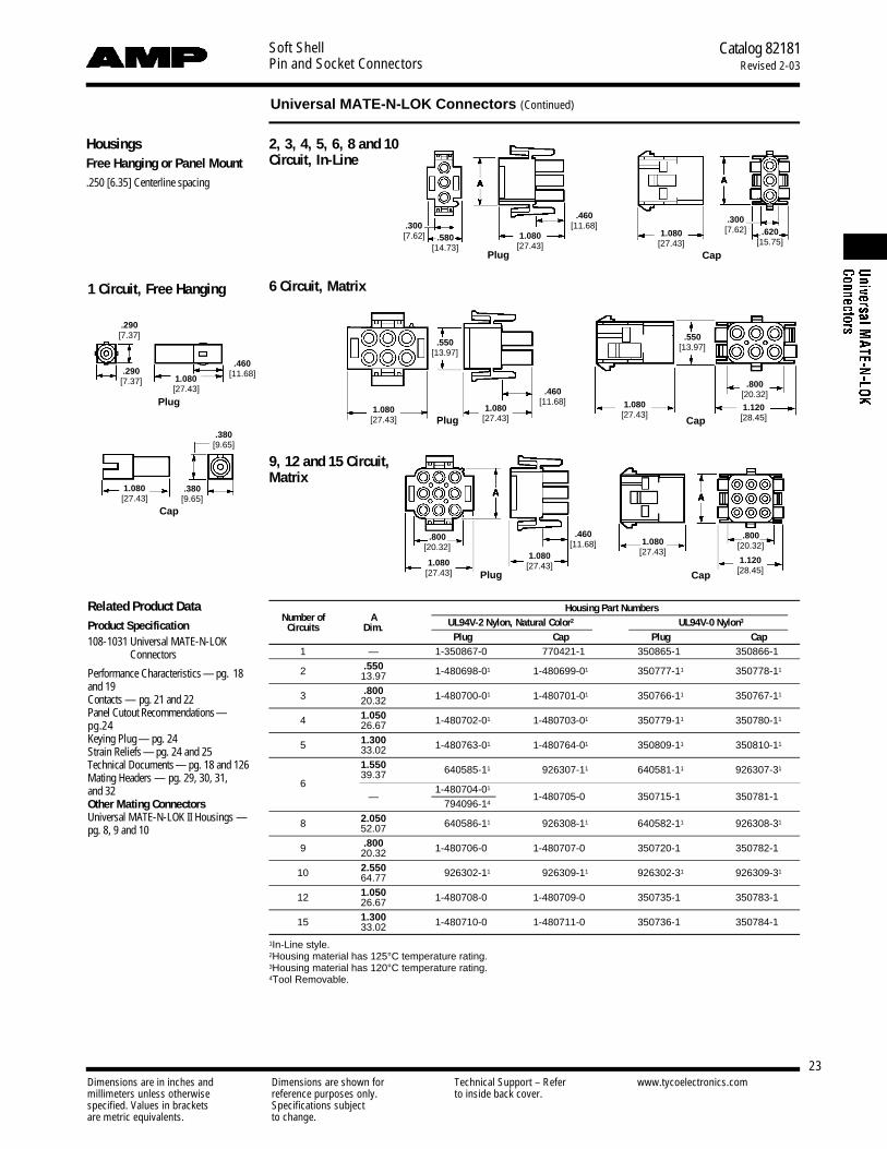
HousingsFree Hanging or Panel Mount.250 [6.35] Centerline spacing
2, 3, 4, 5, 6, 8 and 10Circuit, In-Line
6 Circuit, Matrix
9, 12 and 15 Circuit,Matrix
Number of AHousing Part Numbers
UL94V-2 Nylon, Natural Color2 UL94V-0 Nylon3Circuits Dim.
Plug Cap Plug Cap1 — 1-350867-01 1-770421-11 350865-11 350866-11
2 .550 1-480698-01 1-480699-01 350777-11 350778-1113.97
3 .800 1-480700-01 1-480701-01 350766-11 350767-1120.32
4 1.050 1-480702-01 1-480703-01 350779-11 350780-1126.67
5 1.300 1-480763-01 1-480764-01 350809-11 350810-1133.021.550 1-640585-11 1-926307-11 640581-11 926307-3139.37
6—
1-480704-01
1-480705-01 350715-11 350781-11
1-794096-14
8 2.050 1-640586-11 1-926308-11 640582-11 926308-3152.07
9 .800 1-480706-01 1-480707-01 350720-11 350782-1120.32
10 2.550 1-926302-11 1-926309-11 926302-31 926309-3164.77
12 1.050 1-480708-01 1-480709-01 350735-11 350783-1126.67
15 1.300 1-480710-01 1-480711-01 350736-11 350784-1133.02
1In-Line style.2Housing material has 125°C temperature rating.3Housing material has 120°C temperature rating.4Tool Removable.
Related Product DataProduct Specification108-1031 Universal MATE-N-LOK
Connectors
Performance Characteristics — pg. 18and 19Contacts — pg. 21 and 22Panel Cutout Recommendations—p g .2 4Keying Plug — pg. 24Strain Reliefs — pg. 24 and 25Technical Documents— p g . 18 and 126Mating Headers — pg. 29, 30, 31,and 32Other Mating ConnectorsUniversal MATE-N-LOK II Housings —pg. 8, 9 and 10
.580[14.73]
.300[7.62] 1.080
[27.43]
.460[11.68]
1.080[27.43]
.300[7.62] .620
[15.75]
1.080[27.43]
1.080[27.43]
.550[13.97]
.550[13.97]
.460[11.68] 1.080
[27.43]
.800[20.32]
1.120[28.45]
.290[7.37]
.290[7.37] 1.080
[27.43]
.460[11.68]
1.080[27.43]
.380[9.65]
.380[9.65]
.800[20.32]
1.080[27.43]
1.080[27.43]
.460[11.68] 1.080
[27.43]
.800[20.32]
1.120[28.45]
Plug
Cap
Plug
Plug
Plug Cap
Cap
Cap
Universal MATE-N-LOK Connectors (Continued)
1 Circuit, Free Hanging
Dimensions are in inches and Dimensions are shown for Technical Support – Refer www.tycoelectronics.commillimeters unless otherwise reference purposes only. to inside back cover.specified. Values in brackets Specifications subjectare metric equivalents. to change.
Soft ShellPin and Socket Connectors
Catalog 82181Revised 2-03
24
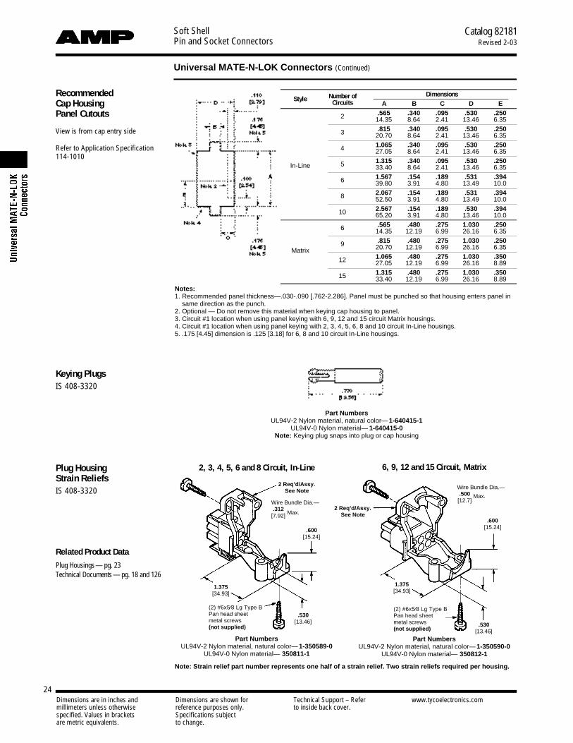
Keying PlugsIS 408-3320
Plug HousingStrain ReliefsIS 408-3320
Related Product Data
Plug Housings— pg. 23Technical Documents — pg. 18 and 126
Number of DimensionsStyle Circuits A B C D E
2 .565 .340 .095 .530 .25014.35 8.64 2.41 13.46 6.35
3 .815 .340 .095 .530 .25020.70 8.64 2.41 13.46 6.35
4 1.065 .340 .095 .530 .25027.05 8.64 2.41 13.46 6.35
In-Line 5 1.315 .340 .095 .530 .25033.40 8.64 2.41 13.46 6.35
6 1.567 .154 .189 .531 .39439.80 3.91 4.80 13.49 10.0
8 2.067 .154 .189 .531 .39452.50 3.91 4.80 13.49 10.0
10 2.567 .154 .189 .530 .39465.20 3.91 4.80 13.46 10.0
6 .565 .480 .275 1.030 .25014.35 12.19 6.99 26.16 6.35
9 .815 .480 .275 1.030 .250
Matrix 20.70 12.19 6.99 26.16 6.35
12 1.065 .480 .275 1.030 .35027.05 12.19 6.99 26.16 8.89
15 1.315 .480 .275 1.030 .35033.40 12.19 6.99 26.16 8.89
Part NumbersUL94V-2 Nylon material, natural color— 1-350589-0
UL94V-0 Nylon material— 350811-1
2, 3, 4, 5, 6 and 8 Circuit, In-Line 6, 9, 12 and 15 Circuit, Matrix
Part NumbersUL94V-2 Nylon material, natural color— 1-350590-0
UL94V-0 Nylon material— 350812-1
Part NumbersUL94V-2 Nylon material, natural color— 1-640415-1
UL94V-0 Nylon material— 1-640415-0Note: Keying plug snaps into plug or cap housing
Recommended Cap HousingPanel Cutouts
View is from cap entry side
Refer to Application Specification114-1010
Notes:1. Recommended panel thickness—.030-.090 [.762-2.286]. Panel must be punched so that housing enters panel in
same direction as the punch.2. Optional — Do not remove this material when keying cap housing to panel.3. Circuit #1 location when using panel keying with 6, 9, 12 and 15 circuit Matrix housings.4. Circuit #1 location when using panel keying with 2, 3, 4, 5, 6, 8 and 10 circuit In-Line housings.5. .175 [4.45] dimension is .125 [3.18] for 6, 8 and 10 circuit In-Line housings.
1.375[34.93]
.530[13.46]
.600[15.24]
2 Req’d/Assy.See Note
Wire Bundle Dia.—.312
[7.92]
(2) #6x5⁄8 Lg Type BPan head sheetmetal screws (not supplied)
(2) #6x5⁄8 Lg Type BPan head sheetmetal screws (not supplied)
.530[13.46]
.600[15.24]
1.375[34.93]
2 Req’d/Assy.See Note
Wire Bundle Dia.—.500
[12.7]
Universal MATE-N-LOK Connectors (Continued)
Max.
Max.
Note: Strain relief part number represents one half of a strain relief. Two strain reliefs required per housing.

Dimensions are in inches and Dimensions are shown for Technical Support – Refer www.tycoelectronics.commillimeters unless otherwise reference purposes only. to inside back cover.specified. Values in brackets Specifications subjectare metric equivalents. to change.
Soft ShellPin and Socket Connectors
Catalog 82181Revised 2-03
25
Plug orCap HousingStrain ReliefsIS 408-3320
Related Product DataHousings — pg. 23Technical Documents — pg. 18 and 126
Number of A Insert Single Wire Wire BundlePart Numbers
Style Circuits Dim. Supplied Dia. Range Dia. Range UL94V-2 Nylon, UL94V-0 NylonNatural Color
Yes .040-.190 — 1-640719-0 640713-1.960 1.02-4.83
2 24.38No — .200-.350 1-640719-1 640713-25.08-8.89
Yes .040-.190 — 1-640720-0 640714-11.140 1.02-4.83
3 28.96No — .200-.350 641763-1 641945-15.08-8.89
Yes .040-.190 — 641775-1 641776-11.325 1.02-4.83
In-Line4 33.65
No — .200-.350 641775-2 641776-25.08-8.89
Yes .040-.190 — 643030-3 643030-11.530 1.02-4.83
5 38.86No — .200-.350 643030-2 643030-45.08-8.89
Yes .040-.190 — 643585-1 643313-11.780 1.02-4.83
6 45.21No — .200-.350 643585-2 643313-2Note 5 5.08-8.89
Yes .040-.190 — — 643314-12.280 1.02-4.83
8 56.08No — .200-.350 — 643314-2Note 5 5.08-8.89
6 1.030 Yes — .120-.650 1-640721-0 640715-126.16 3.05-16.51
9 1.030 Yes — .120-.650 1-640722-0 640716-126.16 3.05-16.51Matrix
12 1.280 Yes — .150-.750 1-640723-0 640717-132.51 3.81-19.05
15 1.530 Yes — .200-.850 1-640724-0 640718-138.86 5.08-21.59
Notes:1. Cable clamping insert comes attached to strain relief. It can be used to provide additional adjustment for small wire
bundles or discarded.2. Insert to be positioned as shown by dotted lines.3. Strain relief part number represents one-half of a strain relief. Two strain reliefs required per housing.4. Must use cap housing adapters when attaching strain reliefs to a cap housing. Two adapters required per housing.5. Strain reliefs for 6 and 8 circuit In-Line fits plug housings only.
Cap Housing AdaptersThese adapters are designed to anchorthe cap housing strain reliefs to thehousings and prevent the strain reliefhalves from “drawing in” when thescrews are being torqued down to clampthe cable.
IS 408-3320
2, 3, 4, 5, 6, 8, 9,12 and 15 Circuit(Enclosed)
For All Positions Except 2, 6and 8 Circuit Cap Housings
For 2 In-Line and 6 MatrixCircuit Cap Housings Only
UL94V-2 Nylon material, natural color— 641777-1
UL94V-0 Nylon material—641778-1
UL94V-2 Nylon material, natural color— 643182-1UL94V-0 Nylon material—643182-2
1.300[33.02] 1.300
[33.02]
In-Line Matrix
(2) #6x3/8 Lg Type BPan head sheet metalscrews (not supplied)
2 Req’d/Assy.Note 3
2 Req’d/Assy.Note 3
Insert
2 Req’d/Assy.Note 3
Note 2Note
2
Note 1
Universal MATE-N-LOK Connectors (Continued)
(2) #6x5/8 Lg Type BPan head sheet metalscrews (not supplied)
Cap Connector
Enclosed StrainRelief
AdapterNote 4

Soft ShellPin and Socket Connectors
Catalog 82181Revised 2-03
26
Universal MATE-N-LOK Flanged Cap Housings with Twist and Lock Feature
Dimensions are in inches and Dimensions are shown for Technical Support – Refer www.tycoelectronics.commillimeters unless otherwise reference purposes only. to inside back cover.specified. Values in brackets Specifications subjectare metric equivalents. to change.
Product Facts■ Available in a 6, 9, and 12
circuit design■ Designed for household ap-
pliances where a bulkheadconnector system is neededin conjunction with foam-ininsulation
■ Mates with standardUniversal MATE-N-LOK plughousings (page 23)
■ Accepts Universal MATE-N-LOK pin and socketcontacts (page 28)
■ Designed to utilize theSplash Proof/SealedUniversal MATE-N-LOKseals for additional sealingprotection (page 27)
Material and FinishHousing — Nylon, UL 94V-0 or UL 94V-2 ratedContacts — Phosphor Bronze or BrassPlating — Pre-tin or Gold
Related Product DataContacts — Pages 21 and 22Plug Housings — Page 23Seals — Page 27
.115[2.92]
1.365[34.67]
.185[4.69]
1.145[29.08]
2.000[50.80]
.290[7.36]
.010[0.25]
1.080[27.43]
.800[20.32]
.550[13.97]
.675[17.15] 2 Plc.
.510[12.95]
Notes:1. Recommended Panel Thickness:
0.76-2.29 [.030-.090]2. Panel must be punched so that
the housing enters the panel inthe same direction as the punch.
3. Asymmetrical panel cutout pro-vides polarization for Pin 1 loca-tion.
Recommended Panel Cutout(for 6 and 9 Pos. Housings)
Dia.
Dia.
Dia.
Radius
Number of Cap Housing Part NumbersCircuits UL 94V-0 UL 94V-2
6 794760-1 794714-19 794761-1 794715-1
12 794762-1 794716-1
Photo 110793-2
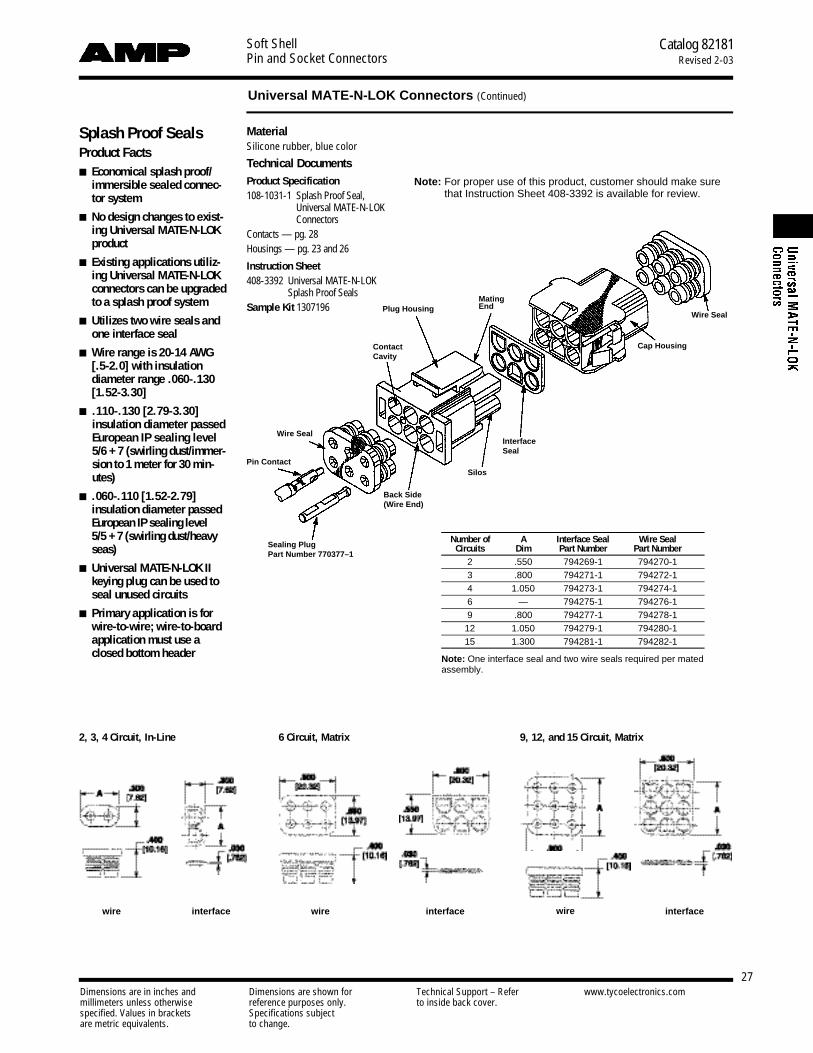
Soft ShellPin and Socket Connectors
Catalog 82181Revised 2-03
27Dimensions are in inches and Dimensions are shown for Technical Support – Refer www.tycoelectronics.commillimeters unless otherwise reference purposes only. to inside back cover.specified. Values in brackets Specifications subjectare metric equivalents. to change.
Universal MATE-N-LOK Connectors (Continued)
Splash Proof SealsProduct Facts■ Economical splash proof/
immersible sealed connec-tor system
■ No design changes to exist-ing Universal M A T E - N - L O Kp r o d u c t
■ Existing applications utiliz-ing Universal M A T E - N - L O Kconnectors can be upgradedto a splash proof system
■ Utilizes two wire seals andone interface seal
■ Wire range is 20-14 AWG[.5-2.0] with insulation diameter range .060-.130[ 1 . 5 2 - 3 . 3 0 ]
■ .110-.130 [2.79-3.30] insulation diameter passedEuropean IP sealing level5/6 + 7 (swirling dust/immer-sion to 1 meter for 30 min-u t e s )
■ .060-.110 [1.52-2.79] insulation diameter passedEuropean IP sealing level 5/5 + 7 (swirling dust/heavys e a s )
■ Universal M A T E - N - L O K I Ikeying plug can be used toseal unused circuits
■ Primary application is forwire-to-wire; wire-to-boardapplication must use aclosed bottom header
2, 3, 4 Circuit, In-Line 6 Circuit, Matrix 9, 12, and 15 Circuit, Matrix
wirewire interfaceinterfacewire interface
Plug HousingMatingEnd
ContactCavity
Wire Seal
Pin Contact
Sealing PlugPart Number 770377–1
Back Side(Wire End)
Silos
InterfaceSeal
Cap Housing
Wire Seal
Number of A Interface Seal Wire SealCircuits Dim Part Number Part Number
2 .550 794269-1 794270-13 .800 794271-1 794272-14 1.050 794273-1 794274-16 — 794275-1 794276-19 .800 794277-1 794278-1
12 1.050 794279-1 794280-115 1.300 794281-1 794282-1
Note: One interface seal and two wire seals required per matedassembly.
MaterialSilicone rubber, blue color
Technical DocumentsProduct Specification108-1031-1 Splash Proof Seal,
Universal MATE-N-LOKConnectors
Contacts — pg. 28Housings — pg. 23 and 26
Instruction Sheet408-3392 Universal MATE-N-LOK
Splash Proof SealsSample Kit 1307196
Note: For proper use of this product, customer should make surethat Instruction Sheet 408-3392 is available for review.
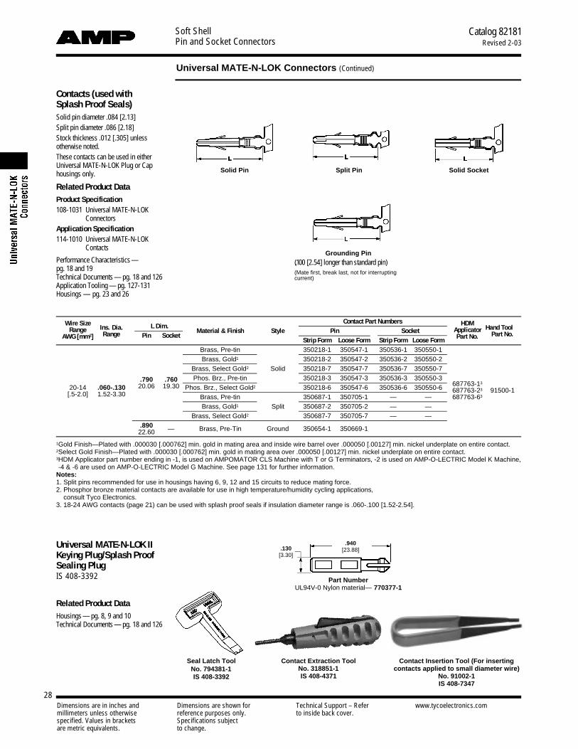
Soft ShellPin and Socket Connectors
Catalog 82181Revised 2-03
28Dimensions are in inches and Dimensions are shown for Technical Support – Refer www.tycoelectronics.commillimeters unless otherwise reference purposes only. to inside back cover.specified. Values in brackets Specifications subjectare metric equivalents. to change.
Universal MATE-N-LOK Connectors (Continued)
Contacts (used with Splash Proof Seals)Solid pin diameter .084 [2.13]Split pin diameter .086 [2.18]Stock thickness .012 [.305] unless otherwise noted.These contacts can be used in eitherUniversal MATE-N-LOK Plug or Caphousings only.
Related Product DataProduct Specification108-1031 Universal MATE-N-LOK
ConnectorsApplication Specification114-1010 Universal MATE-N-LOK
Contacts
Performance Characteristics —pg. 18 and 19Technical Documents — pg. 18 and 126Application Tooling — pg. 127-131Housings — pg. 23 and 26
Solid Pin Split Pin Solid Socket
Grounding Pin(.100 [2.54] longer than standard pin)(Mate first, break last, not for interruptingcurrent)
Wire SizeIns. Dia. L Dim.
Contact Part Numbers HDMHand ToolRange
Range Pin SocketMaterial & Finish Style Pin Socket Applicator
Part No.AWG [mm2] Strip Form Loose Form Strip Form Loose Form Part No.
Brass, Pre-tin 350218-1 350547-1 350536-1 350550-1Brass, Gold1 350218-2 350547-2 350536-2 350550-2
Brass, Select Gold2 Solid 350218-7 350547-7 350536-7 350550-7
.790 .760 Phos. Brz., Pre-tin 350218-3 350547-3 350536-3 350550-3687763-13
20-14 .060-.130 20.06 19.30 Phos. Brz., Select Gold2 350218-6 350547-6 350536-6 350550-6 687763-23 91500-1[.5-2.0] 1.52-3.30 Brass, Pre-tin 350687-1 350705-1 — — 687763-63
Brass, Gold1 Split 350687-2 350705-2 — —Brass, Select Gold2 350687-7 350705-7 — —
.890 — Brass, Pre-Tin Ground 350654-1 350669-122.60
1Gold Finish—Plated with .000030 [.000762] min. gold in mating area and inside wire barrel over .000050 [.00127] min. nickel underplate on entire contact.2Select Gold Finish—Plated with .000030 [.000762] min. gold in mating area over .000050 [.00127] min. nickel underplate on entire contact.3HDM Applicator part number ending in -1, is used on AMPOMATOR CLS Machine with T or G Terminators, -2 is used on AMP-O-LECTRIC Model K Machine,-4 & -6 are used on AMP-O-LECTRIC Model G Machine. See page 131 for further information.
Notes:1. Split pins recommended for use in housings having 6, 9, 12 and 15 circuits to reduce mating force.2. Phosphor bronze material contacts are available for use in high temperature/humidity cycling applications,
consult Tyco Electronics.3. 18-24 AWG contacts (page 21) can be used with splash proof seals if insulation diameter range is .060-.100 [1.52-2.54].
Contact Insertion Tool (For insertingcontacts applied to small diameter wire)
No. 91002-1IS 408-7347
Universal MATE-N-LOK IIKeying Plug/Splash ProofSealing PlugIS 408-3392
Related Product DataHousings — pg. 8, 9 and 10Technical Documents — pg. 18 and 126
.940[23.88].130
[3.30]
Part NumberUL94V-0 Nylon material— 770377-1
Seal Latch ToolNo. 794381-1IS 408-3392
Contact Extraction ToolNo. 318851-1IS 408-4371
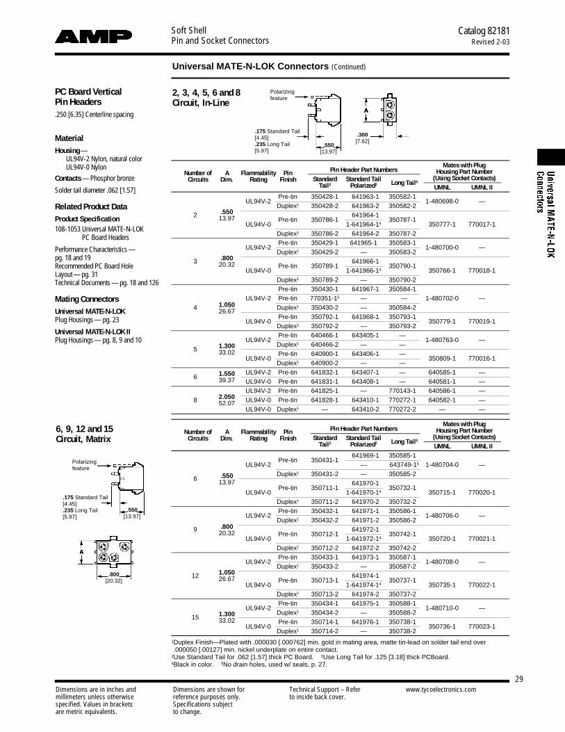
Soft ShellPin and Socket Connectors
Catalog 82181Revised 2-03
29Dimensions are in inches and Dimensions are shown for Technical Support – Refer www.tycoelectronics.commillimeters unless otherwise reference purposes only. to inside back cover.specified. Values in brackets Specifications subjectare metric equivalents. to change.
PC Board VerticalPin Headers.250 [6.35] Centerline spacing
MaterialHousing —
UL94V-2 Nylon, natural color UL94V-0 Nylon
Contacts — Phosphor bronze
Solder tail diameter .062 [1.57]
Related Product DataProduct Specification108-1053 Universal MATE-N-LOK
PC Board Headers
Performance Characteristics —pg. 18 and 19Recommended PC Board Hole Layout — pg. 31Technical Documents — pg. 18 and 126
Mating ConnectorsUniversal MATE-N-LOKPlug Housings— pg. 23
Universal MATE-N-LOK IIPlug Housings— pg. 8, 9 and 10
Pin Header Part NumbersMates with Plug
Number of A Flammability PinStandard Standard Tail
Housing Part NumberCircuits Dim. Rating Finish
Tail2 Polarized2 Long Tail3(Using Socket Contacts)UMNL UMNL II
UL94V-2Pre-tin 350428-1 1-641963-14 350582-1
1-480698-0 —Duplex1 350428-2 1-641963-24 350582-2
2 .550Pre-tin 350786-1
1-641964-14
350787-113.97UL94V-0 1-641964-14 350777-1 770017-1
Duplex1 350786-2 1-641964-24 350787-2
UL94V-2Pre-tin 350429-1 641965-1 350583-1
1-480700-0 —Duplex1 350429-2 — 350583-2
3 .800Pre-tin 350789-1
1-641966-14
350790-120.32UL94V-0 1-641966-14 350766-1 770018-1
Duplex1 350789-2 — 350790-2Pre-tin 350430-1 1-641967-14 350584-1
UL94V-2 Pre-tin 770351-15 — — 1-480702-0 —4 1.050 Duplex1 350430-2 — 350584-226.67
UL94V-0Pre-tin 350792-1 1-641968-14 350793-1
350779-1 770019-1Duplex1 350792-2 — 350793-2
UL94V-2Pre-tin 640466-1 1-643405-14 —
1-480763-0 —5 1.300 Duplex1 640466-2 — —
33.02UL94V-0
Pre-tin 640900-1 1-643406-14 —350809-1 770016-1
Duplex1 640900-2 — —
6 1.550 UL94V-2 Pre-tin 641832-1 1-643407-14 — 640585-1 —39.37 UL94V-0 Pre-tin 641831-1 1-643408-14 — 640581-1 —
2.050UL94V-2 Pre-tin 641825-1 — 770143-1 640586-1 —
8 UL94V-0 Pre-tin 641828-1 1-643410-14 770272-1 640582-1 —52.07UL94V-0 Duplex1 — 1-643410-24 770272-2 — —
Pin Header Part NumbersMates with Plug
Number of A Flammability PinStandard Standard Tail
Housing Part NumberCircuits Dim. Rating Finish
Tail2 Polarized2 Long Tail3(Using Socket Contacts)UMNL UMNL II
Pre-tin 350431-11-641969-14 350585-1
UL94V-2 — 643749-15 1-480704-0 —
6 .550 Duplex1 350431-2 — 350585-213.97
Pre-tin 350711-11-641970-14
350732-1UL94V-0 1-641970-14 350715-1 770020-1
Duplex1 350711-2 1-641970-24 350732-2
UL94V-2Pre-tin 350432-1 1-641971-14 350586-1
1-480706-0 —
.800Duplex1 350432-2 1-641971-24 350586-2
9 20.32 Pre-tin 350712-11-641972-14
350742-1UL94V-0 1-641972-14 350720-1 770021-1
Duplex1 350712-2 1-641972-24 350742-2
UL94V-2Pre-tin 350433-1 1-641973-14 350587-1
1-480708-0 —Duplex1 350433-2 — 350587-2
12 1.050Pre-tin 350713-1
1-641974-14
350737-126.67UL94V-0 1-641974-14 350735-1 770022-1
Duplex1 350713-2 1-641974-24 350737-2
UL94V-2Pre-tin 350434-1 1-641975-14 350588-1
1-480710-0 —15 1.300 Duplex1 350434-2 — 350588-2
33.02UL94V-0
Pre-tin 350714-1 1-641976-14 350738-1350736-1 770023-1
Duplex1 350714-2 — 350738-21Duplex Finish—Plated with .000030 [.000762] min. gold in mating area, matte tin-lead on solder tail end over.000050 [.00127] min. nickel underplate on entire contact.
2Use Standard Tail for .062 [1.57] thick PC Board. 3Use Long Tail for .125 [3.18] thick PCBoard.4Black in color. 5No drain holes, used w/ seals, p. 27.
.175 Standard Tail[4.45].235 Long Tail[5.97]
.300[7.62]
.550[13.97]
.175 Standard Tail[4.45].235 Long Tail[5.97]
.800[20.32]
2, 3, 4, 5, 6 and 8Circuit, In-Line
6, 9, 12 and 15Circuit, Matrix
Polarizingfeature
Polarizingfeature
Universal MATE-N-LOK Connectors (Continued)
.550[13.97]
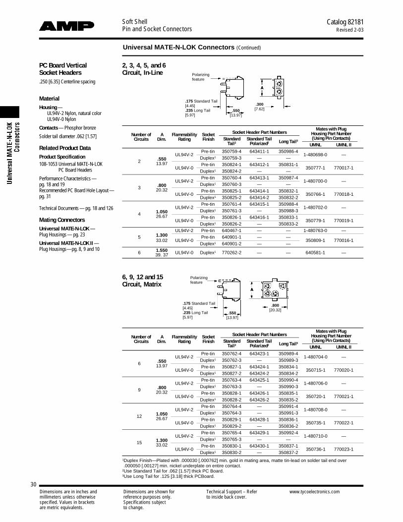
Soft ShellPin and Socket Connectors
Catalog 82181Revised 2-03
30Dimensions are in inches and Dimensions are shown for Technical Support – Refer www.tycoelectronics.commillimeters unless otherwise reference purposes only. to inside back cover.specified. Values in brackets Specifications subjectare metric equivalents. to change.
PC Board VerticalSocket Headers.250 [6.35] Centerline spacing
MaterialHousing —
UL94V-2 Nylon, natural color UL94V-0 Nylon
Contacts — Phosphor bronze
Solder tail diameter .062 [1.57]
Related Product DataProduct Specification108-1053 Universal MATE-N-LOK
PC Board Headers
Performance Characteristics —pg. 18 and 19Recommended PC Board Hole Layout —pg. 31
Technical Documents — pg. 18 and 126
Mating ConnectorsUniversal MATE-N-LOK — Plug Housings— pg. 23
Universal MATE-N-LOK II —Plug Housings—pg. 8, 9 and 10
2, 3, 4, 5, and 6 Circuit, In-Line
6, 9, 12 and 15 Circuit, Matrix
Socket Header Part NumbersMates with Plug
Number of A Flammability SocketStandard Standard Tail
Housing Part NumberCircuits Dim. Rating Finish
Tail2 Polarized2 Long Tail3(Using Pin Contacts)
UMNL UMNL II
UL94V-2Pre-tin 350759-4 643411-1 350986-4
1-480698-0 —2 .550 Duplex1 350759-3 — —
13.97UL94V-0
Pre-tin 350824-1 643412-1 350831-1350777-1 770017-1
Duplex1 350824-2 — —
UL94V-2Pre-tin 350760-4 643413-1 350987-4
1-480700-0 —3 .800 Duplex1 350760-3 — —
20.32UL94V-0
Pre-tin 350825-1 643414-1 350832-1350766-1 770018-1
Duplex1 350825-2 643414-2 350832-2
UL94V-2Pre-tin 350761-4 643415-1 350988-4
1-480702-0 —4 1.050 Duplex1 350761-3 — 350988-3
26.67UL94V-0
Pre-tin 350826-1 643416-1 350833-1350779-1 770019-1
Duplex1 350826-2 — 350833-2
1.300UL94V-2 Pre-tin 640467-1 — — 1-480763-0 —
533.02 UL94V-0
Pre-tin 640901-1 — —350809-1 770016-1
Duplex1 640901-2 — —
6 1.550 UL94V-0 Duplex1 770262-2 — — 640581-1 —39. 37
Socket Header Part NumbersMates with Plug
Number of A Flammability SocketStandard Standard Tail
Housing Part NumberCircuits Dim. Rating Finish
Tail2 Polarized2 Long Tail3(Using Pin Contacts)
UMNL UMNL II
UL94V-2Pre-tin 350762-4 643423-1 350989-4
1-480704-0 —6 .550 Duplex1 350762-3 — 350989-3
13.97UL94V-0
Pre-tin 350827-1 643424-1 350834-1350715-1 770020-1
Duplex1 350827-2 643424-2 350834-2
UL94V-2Pre-tin 350763-4 643425-1 350990-4
1-480706-0 —9 .800 Duplex1 350763-3 — 350990-3
20.32UL94V-0
Pre-tin 350828-1 643426-1 350835-1350720-1 770021-1
Duplex1 350828-2 643426-2 350835-2
UL94V-2Pre-tin 350764-4 — 350991-4
1-480708-0 —12 1.050 Duplex1 350764-3 — 350991-3
26.67UL94V-0
Pre-tin 350829-1 643428-1 350836-1350735-1 770022-1
Duplex1 350829-2 — 350836-2
UL94V-2Pre-tin 350765-4 643429-1 350992-4
1-480710-0 —15 1.300 Duplex1 350765-3 — —
33.02UL94V-0
Pre-tin 350830-1 643430-1 350837-1350736-1 770023-1
Duplex1 350830-2 — 350837-21Duplex Finish—Plated with .000030 [.000762] min. gold in mating area, matte tin-lead on solder tail end over.000050 [.00127] min. nickel underplate on entire contact.
2Use Standard Tail for .062 [1.57] thick PC Board.3Use Long Tail for .125 [3.18] thick PCBoard.
.175 Standard Tail[4.45].235 Long Tail[5.97]
.300[7.62]
.550[13.97]
.175 Standard Tail[4.45].235 Long Tail[5.97]
.800[20.32]
Polarizingfeature
Polarizingfeature
Universal MATE-N-LOK Connectors (Continued)
.550[13.97]

Soft ShellPin and Socket Connectors
31Dimensions are in inches and Dimensions are shown for Technical Support – Refer www.tycoelectronics.commillimeters unless otherwise reference purposes only. to inside back cover.specified. Values in brackets Specifications subjectare metric equivalents. to change.
RecommendedPC BoardHole Layoutsfor Pin and SocketVertical Headers
Related Product DataVertical Headers — pg. 29 and 30
2, 3, 4, 5, 6 and 8Circuit, In-Line
6, 9, 12 and 15Circuit, Matrix
Universal MATE-N-LOK Connectors (Continued)
Note: Polarizing hole .070 [1.78] Dia. required for polarized headers only.
PC Board VerticalPin Headers withACTION PIN Contacts
MaterialHousing — PBT, black
Flammability Rating — UL94V-0
Contacts — Copper alloy, plated withtin-lead over nickel on entire contact
Related Product DataPerformance Characteristics — pg. 18and 19Technical Documents — pg. 18 and 126
Product Specification108-5222 ACTION PIN Universal
MATE-N-LOK HeaderAssembly
Mating ConnectorsUniversal MATE-N-LOK—Plug Housings — pg. 23
Universal MATE-N-LOK II—Plug Housings — pg. 8 and 10
Number of Mates with Plug HousingCircuits A Dim. Part Number Part Number (Using Socket Contacts)
UMNL UMNL II
2 .750 173924-1 1-480698-0 770017-119.05 350777-1
3 1.000 173925-1 1-480700-0 770018-125.40 350766-1
4 1.250 173926-1 1-480702-0 770019-131.75 350779-1
Note: Install in PC Board with arbor tool.
Catalog 82181Revised 2-03

Soft ShellPin and Socket Connectors
Catalog 82181Revised 2-03
32Dimensions are in inches and Dimensions are shown for Technical Support – Refer www.tycoelectronics.commillimeters unless otherwise reference purposes only. to inside back cover.specified. Values in brackets Specifications subjectare metric equivalents. to change.
PC Board Right-AnglePin and Socket Headers.250 [6.35] Centerline spacing
MaterialHousing — Nylon
Contacts — Phosphor bronzeSolder tail width .052 [1.32]
Related Product DataProduct Specification108-1053 Universal MATE-N-LOK
PC Board HeadersPerformance Characteristics — pg. 18and 19Technical Documents — pg. 18 and 126
Mating ConnectorsUniversal MATE-N-LOKPlug Housings— pg. 23
Universal MATE-N-LOK IIPlug Housings— pg. 8 and 10
Test Connectors(with spring loaded contacts)
MaterialHousing — Nylon
Flammability Rating — UL94V-0
Related Product DataMating Connectors — Housings andheaders having the same number of circuits. The housings can have pin orsocket contacts, or a combination of both.Mating Housings — pg. 23Mating Headers — pg. 29, 30 and 31Other Mating ConnectorsUniversal MATE-N-LOK II Housings —pg. 8, 9 and 10
Notes:1. Test probes have 5 amp maxi-
mum current rating. 1,000,000 cycles.
2. Test Connector housings are ofthe same configuration as stan-dard housings. Refer to page 23for dimensional specifications.
Right-Angle Header Part Numbers
No. of Dimensions Contact UL94V-2 UL94V-0Circuits A B C Finish
Pin Socket Mates with Pin SocketMates with
UMNL UMNL II
.550 1.245 .830 Pre-tin — — —1-350942-0 643226-1
2 770994-12 — 350777-1 770017-113.97 31.62 21.08Duplex1 — — — 2-350942-0 —
3 .800 1.495 1.080 Pre-tin — ——
1-350943-0 643228-1350766-1 770018-120.32 37.97 27.43 Duplex1 — — 2-350943-0 643228-2
4 1.050 1.745 1.330 Pre-tin 1-350948-0 —1-480702-0
1-350944-0 643230-1350779-1 770019-126.67 44.32 33.78 Duplex1 — — 2-350944-0 643230-2
5 1.300 1.995 1.580 Pre-tin 1-350949-0 —1-480763-0
1-350945-0 643232-1350809-1 770016-133.02 50.67 40.13 Duplex1 — — 2-350945-0 643232-2
6 1.550 2.245 1.830 Pre-tin 1-640587-1643235-1 1-640585-1
1-640583-1 643234-1640581-1 —39.37 57.02 46.48 Duplex1 — 1-640583-2 643234-2
8 2.050 2.745 2.330 Pre-tin —643237-1 1-640586-1
1-640584-1 643236-1640582-1 —52.07 69.72 59.18 Duplex1 — 1-640584-2 643236-2
1Duplex Finish—Plated with .000030 [.000762] min. gold in mating area, matte tin-lead on solder tail end over.000050 [.00127] min. nickel underplate on entire contact.
2Black in color.
Number of Part NumbersCircuits Plug Cap
2 1-350848-2 1-350849-23 1-350848-3 1-350849-34 1-350848-4 1-350849-45 1-350848-5 1-350849-56 1-350848-6 1-350849-69 1-350848-9 1-350849-912 1-350848-2 1-350849-215 1-350848-5 1-350849-5
2, 3, 4 and 5 Circuit,In-Line
6, 9, 12 and 15 Circuit,Matrix
.680[17.27]
.360[9.14]
.250[6.35]
.160[4.06]
Plug
Plug
Cap
Cap
.084 [2.13] Dia. PinMates withUniversalMATE-N-LOKSockets
Recommended PC Board Hole Layout.062 [1.57] Board Thickness
Universal MATE-N-LOK Connectors (Continued)
Typ.
2, 3, 4, 5, 6 and 8 Circuit, In-line
Use 6-32 UNC Pan Head Screw3/8 [9.53] long for mounting
(Not Supplied)
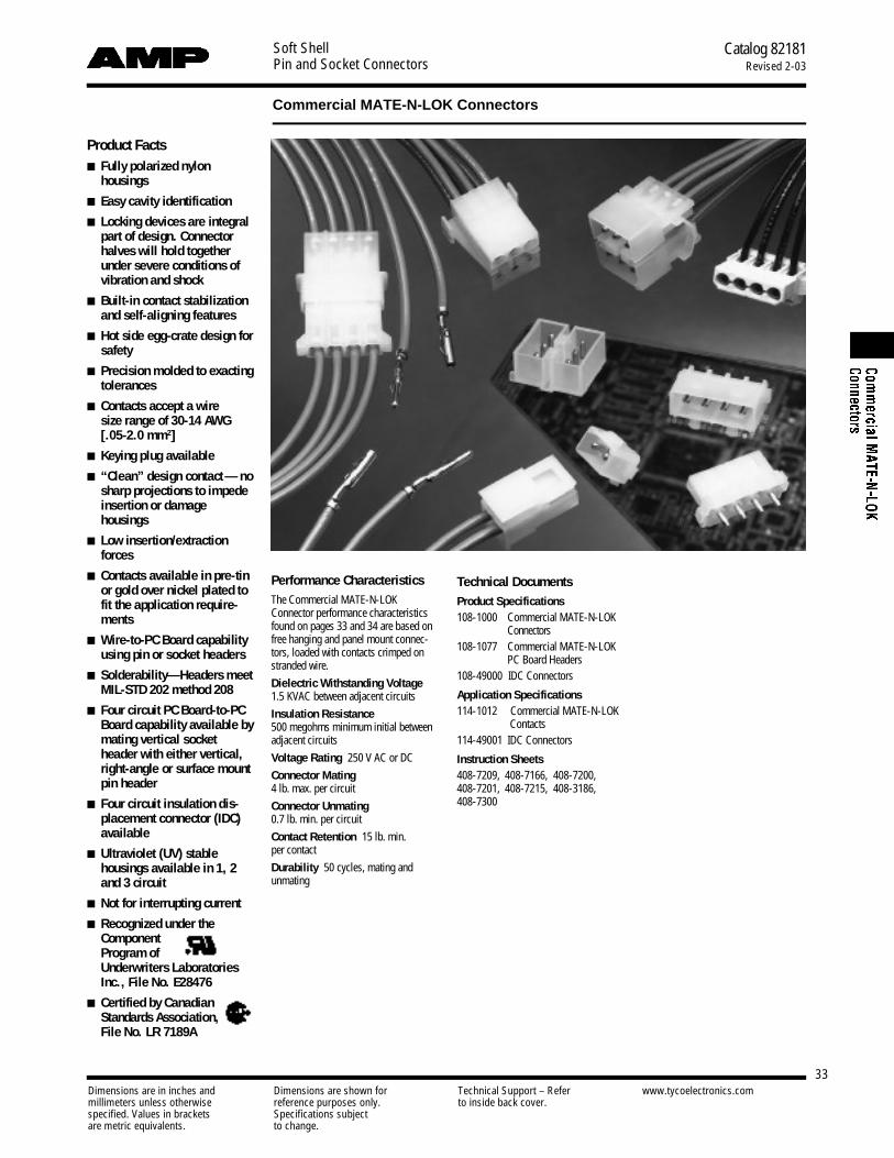
Soft ShellPin and Socket Connectors
Catalog 82181Revised 2-03
33Dimensions are in inches and Dimensions are shown for Technical Support – Refer www.tycoelectronics.commillimeters unless otherwise reference purposes only. to inside back cover.specified. Values in brackets Specifications subjectare metric equivalents. to change.
Commercial MATE-N-LOK Connectors
Performance CharacteristicsThe Commercial MATE-N-LOKConnector performance characteristicsfound on pages 33 and 34 are based onfree hanging and panel mount connec-tors, loaded with contacts crimped onstranded wire.
Dielectric Withstanding Voltage1.5 KVAC between adjacent circuits
Insulation Resistance500 megohms minimum initial between adjacent circuits
Voltage Rating 250 V AC or DC
Connector Mating4 lb. max. per circuit
Connector Unmating0.7 lb. min. per circuit
Contact Retention 15 lb. min. per contact
Durability 50 cycles, mating and unmating
Product Facts■ Fully polarized nylon
h o u s i n g s
■ Easy cavity identification
■ Locking devices are integralpart of design. Connectorhalves will hold togetherunder severe conditions ofvibration and shock
■ Built-in contact stabilizationand self-aligning features
■ Hot side egg-crate design fors a f e t y
■ Precision molded to exactingt o l e r a n c e s
■ Contacts accept a wire size range of 30-14 AWG[.05-2.0 mm2]
■ Keying plug available
■ “Clean” design contact — n osharp projections to impedeinsertion or damage h o u s i n g s
■ Low insertion/extractionf o r c e s
■ Contacts available in pre-tinor gold over nickel plated tofit the application require-m e n t s
■ W i r e - t o -PC Board capabilityusing pin or socket headers
■ Solderability—Headers meetMIL-STD 202 method 208
■ Four circuit PC Bo a r d - t o -P CBoard capability available bymating vertical socketheader with either vertical,right-angle or surface mountpin header
■ Four circuit insulation dis-placement connector (IDC)a v a i l a b l e
■ Ultraviolet (UV) stable housings available in 1, 2and 3 circuit
■ Not for interrupting current
■ Recognized under theComponent Program of Underwriters LaboratoriesInc., File No. E28476
■ Certified by CanadianStandards Association,File No. LR 7189A
Technical DocumentsProduct Specifications108-1000 Commercial MATE-N-LOK
C o n n e c t o r s108-1077 Commercial MATE-N-LOK
PC Board Headers108-49000 IDC Connectors
Application Specifications114-1012 Commercial MATE-N-LOK
Contacts114-49001 IDC Connectors
Instruction Sheets408-7209, 408-7166, 408-7200,408-7201, 408-7215, 408-3186, 408-7300
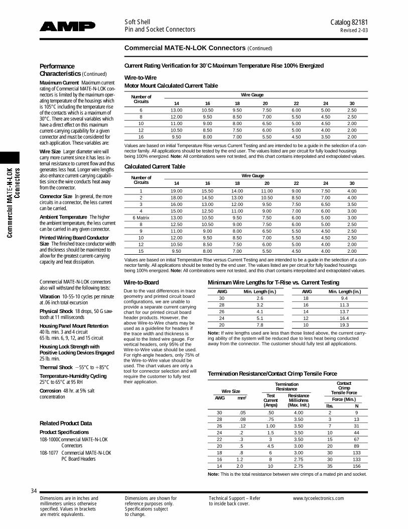
Soft ShellPin and Socket Connectors
Catalog 82181Revised 2-03
34
Commercial MATE-N-LOK Connectors (Continued)
Dimensions are in inches and Dimensions are shown for Technical Support – Refer www.tycoelectronics.commillimeters unless otherwise reference purposes only. to inside back cover.specified. Values in brackets Specifications subjectare metric equivalents. to change.
PerformanceCharacteristics (Continued)
Maximum Current Maximum currentrating of Commercial MATE-N-LOK con-nectors is limited by the maximum oper-ating temperature of the housings whichis 105°C including the temperature riseof the contacts which is a maximum of30°C. There are several variables whichhave a direct effect on this maximumcurrent-carrying capability for a givenconnector and must be considered foreach application. These variables are:
Wire Size Larger diameter wire willcarry more current since it has less in-ternal resistance to current flow and thusgenerates less heat. Longer wire lengthsalso enhance current-carrying capabili-ties since the wire conducts heat awayfrom the connector.
Connector Size In general, the morecircuits in a connector, the less currentcan be carried.
Ambient Temperature The higherthe ambient temperature, the less currentcan be carried in any given connector.
Printed Wiring Board ConductorSize The finished trace conductor widthand thickness should be maximized toallow for the greatest current-carryingcapacity and heat dissipation.
Commercial MATE-N-LOK connectorsalso will withstand the following tests:
Vibration 10-55-10 cycles per minuteat .06 inch total excursion
Physical Shock 18 drops, 50 G saw-tooth at 11 milliseconds
Housing Panel Mount Retention 40 lb. min. 3 and 4 circuit65 lb. m i n . 6, 9, 12, and 15 circuit
Housing Lock Strength withPositive Locking Devices Engaged25 lb. min.
Thermal Shock 255°C to 185°C
Temperature-Humidity Cycling25°C to 65°C at 95 RH
Corrosion 48 hr. at 5% salt concentration
Related Product DataProduct Specifications108-1000 Commercial MATE-N-LOK
C o n n e c t o r s108-1077 Commercial MATE-N-LOK
PC Board Headers
Current Rating Verification for 308C Maximum Temperature Rise 100% Energized
Wire-to-WireMotor Mount Calculated Current Table
Number of Wire GaugeCircuits 14 16 18 20 22 24 30
6 13.00 10.50 9.50 7.50 6.00 5.00 2.508 12.00 9.50 8.50 7.00 5.50 4.50 2.50
10 11.00 9.00 8.00 6.50 5.00 4.50 2.0012 10.50 8.50 7.50 6.00 5.00 4.00 2.0016 9.50 8.00 7.00 5.50 4.50 3.50 2.00
Values are based on initial Temperature Rise versus Current Testing and are intended to be a guide in the selection of a con-nector family. All applications should be tested by the end user. The values listed are per circuit for fully loaded housingsbeing 100% energized. N o t e : All combinations were not tested, and this chart contains interpolated and extrapolated values.
Calculated Current Table
Number of Wire GaugeCircuits 14 16 18 20 22 24 30
1 19.00 15.50 14.00 11.00 9.00 7.50 4.002 18.00 14.50 13.00 10.50 8.50 7.00 4.003 16.00 13.00 12.00 9.50 7.50 6.50 3.504 15.00 12.50 11.00 9.00 7.00 6.00 3.00
6 Matrix 13.00 10.50 9.50 7.50 6.00 5.00 3.008 12.50 10.50 9.00 7.50 6.00 5.00 2.509 11.00 9.00 8.00 6.50 5.50 4.50 2.50
10 12.00 9.50 8.50 7.00 5.50 4.50 2.5012 10.50 8.50 7.50 6.00 5.00 4.00 2.0015 9.50 8.00 7.00 5.50 4.50 4.00 2.00
Values are based on initial Temperature Rise versus Current Testing and are intended to be a guide in the selection of a con-nector family. All applications should be tested by the end user. The values listed are per circuit for fully loaded housingsbeing 100% energized. N o t e : All combinations were not tested, and this chart contains interpolated and extrapolated values.
Termination ContactResistance Crimp
Wire SizeTest Resistance
Tensile ForceAWG mm2
Current Milliohms Force (Min.)(Amps) (Max. Init.) lbs. N
30 .05 .50 4.00 2 928 .08 .75 3.50 3 1326 .12 1.00 3.50 7 3124 .2 1.5 3.50 10 4422 .3 3 3.50 15 6720 .5 4.5 3.00 20 8918 .8 6 3.00 30 13316 1.2 8 2.75 30 13314 2.0 10 2.75 35 156
N o t e: This is the total resistance between wire crimps of a mated pin and socket.
Wire-to-BoardDue to the vast differences in tracegeometry and printed circuit boardconfigurations, we are unable to provide a separate current carryingchart for our printed circuit boardheader products. However, theabove Wire-to-Wire charts may beused as a guideline for headers ifthe trace width and thickness isequal to the listed wire gauge. Forvertical headers, only 95% of theWire-to-Wire value should be used.For right-angle headers, only 75% ofthe Wire-to-Wire value should beused. The chart values are only atool for connector selection and will require the customer to fully testtheir application.
Minimum Wire Lengths for T-Rise vs. Current TestingAWG Min. Length (in.) AWG Min. Length (in.)30 2.6 18 9.428 3.2 16 11.326 4.1 14 13.724 5.1 12 16.420 7.8 10 19.3
Note: If wire lengths used are less than those listed above, the current carry-ing ability of the system will be reduced due to less heat being conductedaway from the connector. The customer should fully test all applications.
Termination Resistance/Contact Crimp Tensile Force

Soft ShellPin and Socket Connectors
Catalog 82181Revised 2-03
35
Commercial MATE-N-LOK Connectors (Continued)
Dimensions are in inches and Dimensions are shown for Technical Support – Refer www.tycoelectronics.commillimeters unless otherwise reference purposes only. to inside back cover.specified. Values in brackets Specifications subjectare metric equivalents. to change.
Commercial MATE-N-LOK Connector Mating CombinationsConnector Part Number Mating Connector Part Number
PC Board HeadersNumber
Flammability Housing Connector Housing HousingVertical Vertical
ofRating
StyleType Part No. Part No. Type
Pin Right-Angle SocketCircuits Plating Standard Long Pin Standard Long
Tail Tail Tail Tail1-480350-0 Pin: FH — — — — — —
Socket: FH 1-480349-01-480351-0 Pin: FH — — — — — —1 UL94V-2 In-Line Positive Lock
Socket: FH 1-480400-0 1-480401-1 Pin: FH — — — — — —UV Stable UV Stable
Socket: FH 1-480318-0 1-480319-0 Pin: FHPre-tin 1-350209-1 350422-1 794120-1 — —
Duplex1 1-350209-2 — — — —
Socket: FH 1-480393-1 1-480498-1 Pin: FH — — — — — —2 UL94V-2 In-Line UV Stable UV Stable
Socket: FH1-480720-0 1-794012-1
Pin: FH Pre-tin 1-350539-1 350540-1 — — —Positive Lock Positive Lock Duplex1 1-350539-2 — — — —
Socket: FH 1-480303-0Pre-tin 1-350210-1 350423-1 643488-1 — —
1-480305-0 Pin: FH Duplex1 1-350210-2 — — — —
Socket: PM 1-480304-0 — — — — — —3 UL94V-2 In-Line Socket: FH
1-480721-0 — —Pre-tin 1-350541-1 350542-1 — — —
Positive Lock Duplex1 1-350541-2 — — — —
Socket: FH 1-480388-0 1-480387-0 Pin: FH — — — — — —UV Stable UV Stable
4 See next page for 4 position mating combinations
1-480340-0 Pin: FH Pre-tin 1-380999-0 350425-1 — — —Socket: FH
1-480270-0Positive Lock
Positive Lock1-480271-0 Pin: MM Duplex1 2-380999-0 350425-2 — — —Positive Lock
6 UL94V-2 Matrix Socket: PM1-480273-0 1-480276-0
Pin: PM Pre-tin — — — — —Positive Lock Positive Lock Duplex1 — — — — —
Pin: PM1-480276-0 1-480273-0
Socket: PM Pre-tin — — — 350641-1 350576-1Positive Lock Positive Lock Duplex1 — — — — —
1-480345-0 Pin: FH Pre-tin 1-350212-1 350426-1 — — —8 UL94V-2
Dual Socket: FH1-480283-0
Positive LockRow Positive Lock
1-480284-0 Pin: MM Duplex1 1-350212-2 350426-2 — — —Positive Lock
9 UL94V-2 MatrixPin: PM
1-480277-0 1-480274-0Socket: PM Pre-tin — — — 350642-1 350577-1
Positive Lock Positive Lock Duplex1 — — — 350642-2 —
1-480339-0 Pin: FH Pre-tin 1-380991-0 350219-1 — — —10 UL94V-2
Dual Socket: FH1-480285-0
Positive LockRow Positive Lock
1-480286-0 Pin: MM Duplex1 2-380991-0 — — — —Positive Lock
Dual Socket: MM1-480287-0 1-480288-0
Pin: MM Pre-tin 1-350213-1 350220-1 — — —
12 UL94V-2Row Positive Lock Positive Lock Duplex1 1-350213-1 350220-2 — — —
MatrixPin: PM
1-480278-0 1-480275-0Socket: PM Pre-tin — — — 350643-1 350578-1
Positive Lock Positive Lock Duplex1 — — — — —
15 UL94V-2 MatrixPin: PM
1-480324-0 1-480323-0Socket: PM Pre-tin — — — 350644-1 350579-1
Positive Lock Positive Lock Duplex1 — — — — —
16 UL94V-2Dual Socket: MM
1-480438-0 1-480439-0Pin: MM Pre-tin 350214-1 350427-1 — — —
Row Positive Lock Positive Lock Duplex1 350214-2 350427-2 — — —
FH: Free Hanging PM: Panel Mount MM: Motor Mount1Duplex Finish — Plated with .000030 [.000762] min. gold in mating area, matte tin-lead on solder tail end over .000050 [.00127] min. nickel underplate on entire contact.

Soft ShellPin and Socket Connectors
Catalog 82181Revised 2-03
36
Commercial MATE-N-LOK Connectors (Continued)
Dimensions are in inches and Dimensions are shown for Technical Support – Refer www.tycoelectronics.commillimeters unless otherwise reference purposes only. to inside back cover.specified. Values in brackets Specifications subjectare metric equivalents. to change.

Soft ShellPin and Socket Connectors
Catalog 82181Revised 2-03
37
Commercial MATE-N-LOK Connectors (Continued)
Dimensions are in inches and Dimensions are shown for Technical Support – Refer www.tycoelectronics.commillimeters unless otherwise reference purposes only. to inside back cover.specified. Values in brackets Specifications subjectare metric equivalents. to change.
Wire Size Ins. Dia.Contact Part Numbers HDM Hand ToolRange Material & Finish Pin Socket Applicator
AWG [mm2] RangeStrip Form Loose Form Strip Form Loose Form Part No. Part No.
30-22 .040-.075Brass, Pre-tin 350079-1 61174-1 350078-1 61173-1 466426-13
[.05-.3] 1.02-1.91 Phos. Brz., Pre-tin 350079-4 — 350078-4 61173-4 466426-23 91515-1Brass, Gold1 350079-5 61174-5 350078-5 61173-5 466426-33
Brass, Pre-tin 61116-1 60618-1 61314-1 60617-1
24-18 .060-.100Phos. Brz., Pre-tin 61116-4 60618-4 61314-4 60617-4 466320-13
91512-1Brass, Gold1 61116-5 60618-5 61314-5 60617-5 466320-23[.2-.8] 1.52-2.54
Phos. Brz., Select Gold2 61116-6 60618-6 61314-6 60617-6 466320-43 91528-14
Brass, Select Gold2 61116-7 — 61314-7 —Brass, Pre-tin 61118-1 60620-1 61117-1 60619-1
20-14 .100-.130Phos. Brz., Pre-tin 61118-4 60620-4 61117-4 60619-4 687763-13
Brass, Gold1 61118-5 60620-5 61117-5 60619-5 687763-23 91504-1[.5-2.0] 2.54-3.30Phos. Brz., Gold1 61118-6 — 61117-6 60619-7 687763-63
Brass, Select Gold2 61118-7 — 61117-7 —(2) 18 [.8] or (2) .115 Max. Brass, Pre-tin 350558-1 350639-1 350557-1 — 687898-13
(1) 18 [.8] and 2.92 687898-23 91504-1(1) 16 [1.2] (stacked) Phos. Brz., Pre-tin 350558-4 — 350557-4 350638-4 687898-43
1Gold Finish—Plated with .000030 [.000762] min. gold in mating area and inside wire barrel over .000050 [.00127] min. nickel underplate on entire contact.2Select Gold Finish—Plated with .000030 [.000762] min. gold in mating area over .000050 [.00127] min. nickel underplate on entire contact.3HDM Applicator part number ending in -1 is used on AMPOMATOR CLS Machine with T or G Terminators, -2 is used on AMP-O-LECTRIC Model K Machine;-3, -4, or -6 is used on AMP-O-LECTRIC Model G Machine. See page 132 for further information.
4Use Hand Tool No. 91528-1 for .043-.075 [1.09-1.90] insulation diameter.Notes:1. Extraction Tools: Pins — No. 1-305183-1 (IS 408-7158); Sockets — No. 1-305183-2 (IS 408-7158); Pins and Sockets — No. 465644-1 (IS 408-7211)2. Insertion Tools: No. 455830-1 (IS 408-7984)
ContactsPin diameter .084 [2.13]Stock thickness .012 [.305] These contacts are to be used inCommercial MATE-N-LOK housingsonly.
Related Product DataProduct Specification108-1000 Commercial MATE-N-LOK
C o n n e c t o r s
Application Specification114-1012 Commercial MATE-N-LOK
ContactsPerformance Characteristics —pg. 33 and 34Housings — pg. 39, 40, 41 and 42Technical Documents — pg. 33 and 126Application Tooling — pg. 127-130 and132
Pin Socket
Commoning Tabs
Material and FinishBrass, tin platedStock thickness .008 [.203]
Number of Dimensions PartHoles A B Number
2 .377 .203 60843-19.58 5.16
2 .355 .195 350444-19.02 4.95
3 .579 .203 60842-114.71 5.16
3 .550 .195 350444-213.97 4.95
Note: Commoning tabs are designed to be used with pin housings.
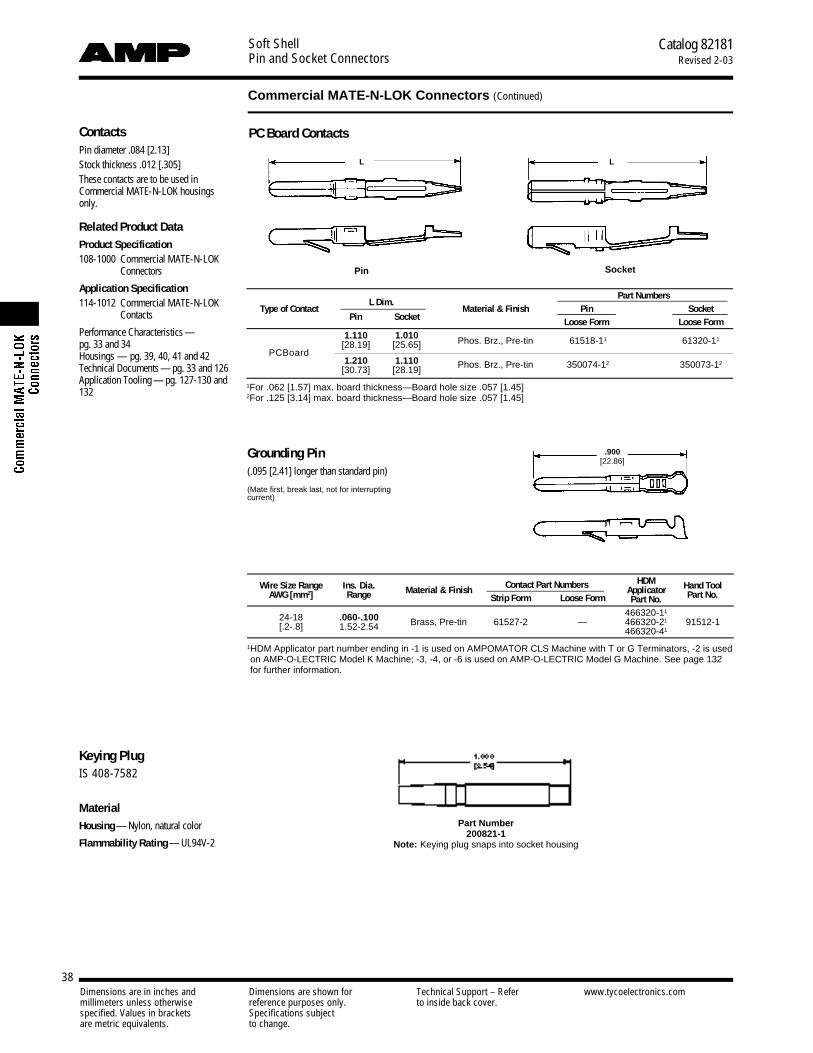
Soft ShellPin and Socket Connectors
Catalog 82181Revised 2-03
38
Commercial MATE-N-LOK Connectors (Continued)
Dimensions are in inches and Dimensions are shown for Technical Support – Refer www.tycoelectronics.commillimeters unless otherwise reference purposes only. to inside back cover.specified. Values in brackets Specifications subjectare metric equivalents. to change.
ContactsPin diameter .084 [2.13]Stock thickness .012 [.305]These contacts are to be used inCommercial MATE-N-LOK housingsonly.
Related Product DataProduct Specification108-1000 Commercial MATE-N-LOK
C o n n e c t o r s
Application Specification114-1012 Commercial MATE-N-LOK
Contacts
Performance Characteristics —pg. 33 and 34Housings — pg. 39, 40, 41 and 42Technical Documents — pg. 33 and 126Application Tooling — pg. 127-130 and132
Part Number 200821-1
Note: Keying plug snaps into socket housing
Pin Socket
Keying PlugIS 408-7582
MaterialHousing — Nylon, natural color
Flammability Rating — UL94V-2
Part NumbersType of Contact
L Dim.Material & Finish Pin Socket
Pin Socket Loose Form Loose Form
PCBoard
1.110 1.010 Phos. Brz., Pre-tin 61518-11 61320-11[28.19] [25.65]
1.210 1.110 Phos. Brz., Pre-tin[30.73] [28.19] 350074-12 350073-12
1For .062 [1.57] max. board thickness—Board hole size .057 [1.45]2For .125 [3.14] max. board thickness—Board hole size .057 [1.45]
L L
.900[22.86]
Grounding Pin(.095 [2.41] longer than standard pin)
(Mate first, break last, not for interruptingcurrent)
PC Board Contacts
Wire Size Range Ins. Dia. Contact Part Numbers HDM Hand ToolMaterial & Finish ApplicatorAWG [mm2] Range Strip Form Loose Form Part No. Part No.
24-18 .060-.100 466320-11
Brass, Pre-tin 61527-2 — 466320-21 91512-1[.2-.8] 1.52-2.54 466320-41
1HDM Applicator part number ending in -1 is used on AMPOMATOR CLS Machine with T or G Terminators, -2 is usedon AMP-O-LECTRIC Model K Machine; -3, -4, or -6 is used on AMP-O-LECTRIC Model G Machine. See page 132for further information.
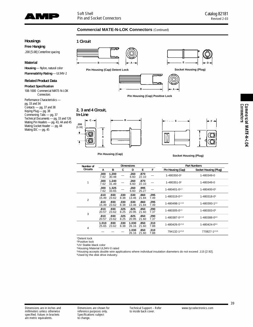
Soft ShellPin and Socket Connectors
Catalog 82181Revised 2-03
39
Commercial MATE-N-LOK Connectors (Continued)
Dimensions are in inches and Dimensions are shown for Technical Support – Refer www.tycoelectronics.commillimeters unless otherwise reference purposes only. to inside back cover.specified. Values in brackets Specifications subjectare metric equivalents. to change.
HousingsFree Hanging.200 [5.08] Centerline spacing
MaterialHousing — Nylon, natural color
Flammability Rating — UL94V-2
Related Product DataProduct Specification108-1000 Commercial MATE-N-LOK
C o n n e c t o r s
Performance Characteristics —pg. 33 and 34Contacts — pg. 37 and 38Keying Plug — pg. 38Commoning Tabs — pg. 37Technical Documents — pg. 33 and 126Mating Pin Headers — pg. 43, 44 and 45Mating Socket Header — pg. 44Mating IDC — pg. 45
1 Circuit
Pin Housing (Cap)
Pin Housing (Cap) Positive Lock
Socket Housing (Plug)
Number of Dimensions Part NumbersCircuits A B C D E F Pin Housing (Cap) Socket Housing (Plug)
.300 1.200 — .260 .870 — 1-480350-01,6 1-480349-04,67.62 30.48 6.60 22.10
1 .300 1.240 — .260 .870 — 1-480351-02,6 1-480349-04,67.62 31.49 6.60 22.10.300 1.325 — .260 .995 — 1-480401-01,3,6 1-480400-03,67.62 33.65 6.60 25.27.610 .930 .330 .530 .860 .295 1-480319-01,5,6 1-480318-05,6
15.49 23.62 8.38 13.46 21.84 7.492
.610 .930 .330 .530 .860 .295 1-480498-11,3,5 1-480393-13,515.49 23.62 8.38 13.46 21.84 7.49.810 .930 .325 .825 .850 .290 1-480305-01,5,6 1-480303-05
20.57 23.62 8.25 20.95 21.60 7.373
.810 .930 .325 .825 .850 .290 1-480387-01,3,5 1-480388-03,520.57 23.62 8.25 20.95 21.60 7.371.010 .930 .330 1.030 .850 .310 1-480426-01,5,6 1-480424-05,6
425.65 23.62 8.38 26.16 21.60 7.88
— — — 1.030 .850 .310 1-794132-14,5,6 1-770827-14,5,626.16 21.60 7.88
1Detent lock2Positive lock3UV Stable black color4Housing Material UL94V-0 rated5Housing accepts double wire applications where individual insulation diameters do not exceed .115 [2.92].6Used by the disk drive industry.
Pin Housing (Cap) Detent Lock Socket Housing (Plug)
2, 3 and 4 Circuit,In-Line
B
C
A
B E
D
F
B
A
A
E D
.200[5.08]
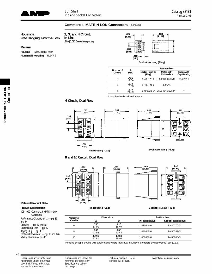
Soft ShellPin and Socket Connectors
Catalog 82181Revised 2-03
40
Commercial MATE-N-LOK Connectors (Continued)
Dimensions are in inches and Dimensions are shown for Technical Support – Refer www.tycoelectronics.commillimeters unless otherwise reference purposes only. to inside back cover.specified. Values in brackets Specifications subjectare metric equivalents. to change.
HousingsFree Hanging, Positive Lock
MaterialHousing— Nylon, natural colorFlammability Rating — UL94V-2
Related Product DataProduct Specification108-1000 Commercial MATE-N-LOK
C o n n e c t o r sPerformance Characteristics — pg. 33and 34Contacts — pg. 37 and 38Commoning Tabs — pg. 37Keying Plug — pg. 38Technical Documents — pg. 33 and 126Mating Headers — pg. 43
8 and 10 Circuit, Dual Row
Pin Housing (Cap) Socket Housing (Plug)
6 Circuit, Dual Row
Pin Housing (Cap) Socket Housing (Plug)
.195[4.95]
.785[19.94]
.360[9.14]
.930[23.62]
.850[21.59]
.725[18.41]
A D
Number of Dimensions Part NumbersCircuits A D Pin Housing (Cap) Socket Housing (Plug)
6 .705 .610 1-480340-04,6 1-480270-01,617.91 15.49
8 .900 .805 1-480345-04,6 1-480283-01,622.86 20.44
10 1.095 1.000 1-480339-04,6 1-480285-01,627.81 25.40
1Housing accepts double wire applications where individual insulation diameters do not exceed .115 [2.92].
Number of APart Numbers
Socket Housing Mates with Mates withCircuits Dim.(Plug) Pin Headers Cap Housing
2 .435 1-480720-0 350539, 350540 794012-111.04
3 .630 1-480721-0 350541 —16.00
4 .830 1-480722-01 3505431, 3505441 —21.09
1Used by the disk drive industry.
2, 3, and 4 Circuit,In-Line.200 [5.08] Centerline spacing
Socket Housing (Plug)
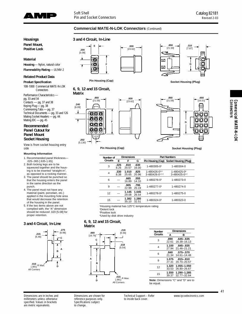
Soft ShellPin and Socket Connectors
Catalog 82181Revised 2-03
41
Commercial MATE-N-LOK Connectors (Continued)
Dimensions are in inches and Dimensions are shown for Technical Support – Refer www.tycoelectronics.commillimeters unless otherwise reference purposes only. to inside back cover.specified. Values in brackets Specifications subjectare metric equivalents. to change.
HousingsPanel Mount,Positive Lock
MaterialHousing— Nylon, natural color
Flammability Rating — UL94V-2
Related Product DataProduct Specification108-1000 Commercial MATE-N-LOK
C o n n e c t o r s
Performance Characteristics —pg. 33 and 34Contacts — pg. 37 and 38Keying Plug — pg. 38Commoning Tabs— pg. 37Technical Documents — pg. 33 and 126Mating Socket Headers — pg. 44Mating IDC — pg. 45
RecommendedPanel Cutout for Panel Mount Socket HousingView is from socket housing entryside
Mounting Information
1. Recommended panel thickness—.025-.065 [.635-1.65].
2. Both locking legs are to besqueezed together and the hous-ing is to be inserted “straight-in”,as opposed to a rocking manner.
3. The panel should be punched so that the housing enters the panelin the same direction as thepunch.
4. The panel must not have any material (paint, porcelain, etc.) applied in the mounting hole areathat would decrease the retentionof the housing in the panel.
5. If the two items above are notcomplied with, the “A” dimensionshould be reduced .020 [5.08] forproper retention.
3 and 4 Circuit, In-Line
3 and 4 Circuit, In-Line 6, 9, 12 and 15 Circuit,Matrix
Pin Housing (Cap)
Pin Housing (Cap)
Socket Housing (Plug)
Socket Housing (Plug)
Number of Dimensions Part NumbersCircuits E F G Pin Housing (Cap) Socket Housing (Plug)
3 .325 .810 .630 1-480305-02 1-480304-08.26 20.57 16.00
4 .330 1.010 .825 1-480426-02,4 1-480425-04
8.38 25.65 20.96 3-480426-01,2,4 3-480425-01,4
6 — .665 .555 1-480276-03 1-480273-016.89 14.10
9 — .905 .795 1-480277-03 1-480274-022.99 20.19
12 — 1.145 1.045 1-480278-03 1-480275-029.08 26.54
15 — 1.382 1.280 1-480324-03 1-480323-035.10 32.511Housing material has 125°C temperature rating2Detent lock3Positive lock4Used by disk drive industry
Number DimensionsCircuits A B
3 .890 .645–.63522.61 16.38–16.13
4 1.100 .845–.83527.94 21.46–21.21
6 .840 .575–.57021.34 14.61–14.48
9 1.075 .815–.81027.31 20.70–20.57
12 1.320 1.055–1.05033.53 26.80–26.67
15 1.550 1.290–1.28539.37 32.77–32.64
Note: Dimensions “C” and “D” are tobe equal.
6, 9, 12 and 15 Circuit,Matrix
.200[5.08]
.240[6.09]
.202[5.130]
.930[23.62]
.930[23.62]
.850[21.59]
.850[21.59]
.850[21.59]
.650[16.51]
.310[7.87]
E
F
F G
G
.215[5.46]
.015[.381]
All Corners
.275[6.98]
A
A
B
B
CC
D
D
.660[16.76]
.219[5.56]
.218[5.54]
R Max.
.015[.381]
All Corners
R Max.

Soft ShellPin and Socket Connectors
Catalog 82181Revised 2-03
42
Commercial MATE-N-LOK Connectors (Continued)
Dimensions are in inches and Dimensions are shown for Technical Support – Refer www.tycoelectronics.commillimeters unless otherwise reference purposes only. to inside back cover.specified. Values in brackets Specifications subjectare metric equivalents. to change.
Number of DimensionsPart Numbers
Circuits E FPin Housing (Cap) Socket Housing (Plug)
UL94V-2 Nylon, Natural Color
6 .705 .610 1-480271-0 1-480270-0117.90 15.49
8 .900 .805 1-480284-0 1-480283-0122.86 20.45
10 1.095 1.000 1-480286-0 1-480285-0127.81 25.4
12 1.290 1.195 1-480288-0 1-480287-032.77 30.35
16 1.680 1.585 1-480439-0 1-480438-042.67 40.26
1Housing accepts double wire applications where individual insulation diame-ters do not exceed .115 [2.92].
Number of ACircuits Dim.
6 .71518.16
8 .91023.11
10 1.10528.07
12 1.30033.02
16 1.69042.93
Mounting Information
1. Recommended panel thickness“E” is .040-.100 [1.02-2.54] and isdependent on “T” and “R”.
2. The pin housing must be insertedin a rocking manner.
3. The panel must be punched sothat the housing enters the panelin the same direction as thepunch.
.585[14.86]
A
AE
R
T
Section A-A
A
.015[.381]
All Corners
R Max.
Note: Motor mount housings may be used inflat panels
Motor Mount, Positive Lock
.195[4.95]
.785[19.94]
.360[9.14]
.930[23.62]
.850[21.59]
.725[18.41]
E F
Pin Housing (Cap) Socket Housing (Plug)
RecommendedPanel Cutout for Motor Mount Pin HousingView is from pin housing entry side.
6, 8, 10, 12 and 16 Circuit,Dual Row
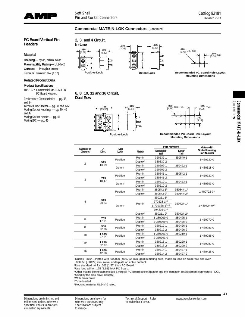
Soft ShellPin and Socket Connectors
Catalog 82181Revised 2-03
43
Commercial MATE-N-LOK Connectors (Continued)
Dimensions are in inches and Dimensions are shown for Technical Support – Refer www.tycoelectronics.commillimeters unless otherwise reference purposes only. to inside back cover.specified. Values in brackets Specifications subjectare metric equivalents. to change.
PC Board Vertical PinHeaders
MaterialHousing — Nylon, natural colorFlammability Rating — UL94V-2Contacts — Phosphor bronzeSolder tail diameter .062 [1.57]
Related Product DataProduct Specifications108-1077 Commercial MATE-N-LOK
PC Board Headers
Performance Characteristics — pg. 33and 34Technical Documents — pg. 33 and 126Mating Socket Housings — pg. 39, 40and 42Mating Socket Header — pg. 44Mating IDC — pg. 45
Detent Lock Recommended PC Board Hole Layout Mounting Dimensions
Recommended PC Board Hole LayoutMounting Dimensions
Positive Lock
Positive Lock
2, 3, and 4 Circuit,In-Line
6, 8, 10, 12 and 16 Circuit,Dual Row
Number of A TypePart Numbers Mates with
Standard2 Long3 Socket HousingCircuits Dim. Lock FinishTail Tail Part Number
PositivePre-tin 350539-1 350540-1
1-480720-02 .515 Duplex1 350539-2 —
13.09Detent
Pre-tin 350209-1 350422-11-480318-0
Duplex1 350209-2 —
PositivePre-tin 350541-1 350542-1
1-480721-03 .715 Duplex1 350541-2 —
18.17Detent
Pre-tin 350210-1 350423-11-480303-0
Duplex1 350210-2 —
PositivePre-tin 350543-15 350544-15
1-480722-05
Duplex1 350543-25 350544-25
.915350211-15
4Pre-tin
770328-15,6
350424-1523.24Detent 1-770328-15,6,7 1-480424-04,5
794236-15,8
Duplex1 350211-25 350424-25
6 .705 PositivePre-tin 1-380999-0 350425-1
1-480270-017.91 Duplex1 2-380999-0 350425-2
8 .900 PositivePre-tin 350212-1 350426-1
1-480283-022.86 Duplex1 350212-2 350426-2
10 1.095 PositivePre-tin 1-380991-0 350219-1
1-480285-027.81 Duplex1 2-380991-0 —
12 1.290 PositivePre-tin 350213-1 350220-1
1-480287-032.77 Duplex1 350213-2 350220-2
16 1.680 PositivePre-tin 350214-1 350427-1
1-480438-042.68 Duplex1 350214-2 350427-2
1Duplex Finish—Plated with .000030 [.000762] min. gold in mating area, matte tin-lead on solder tail end over.000050 [.00127] min. nickel underplate on entire contact.
2Use standard tail for .062 [1.57] thick PC Board.3Use long tail for .125 [3.18] thick PC Board.4Other mating connectors include a vertical PC Board socket header and the insulation displacement connectors (IDC).5Used by the disk drive industry.6With drain holes.7Tube loaded.8Housing material UL94V-0 rated.
.330[8.38]
AA
.375[9.52]
.375[9.52]
.200[5.08]
.330[3.38]
Typ.
.070[1.78]
.070[1.78]
.360[9.14]
.375[9.14]
.785[19.93]
A
Dia. Typ. .195[4.95]
Typ.
Dia. Typ.
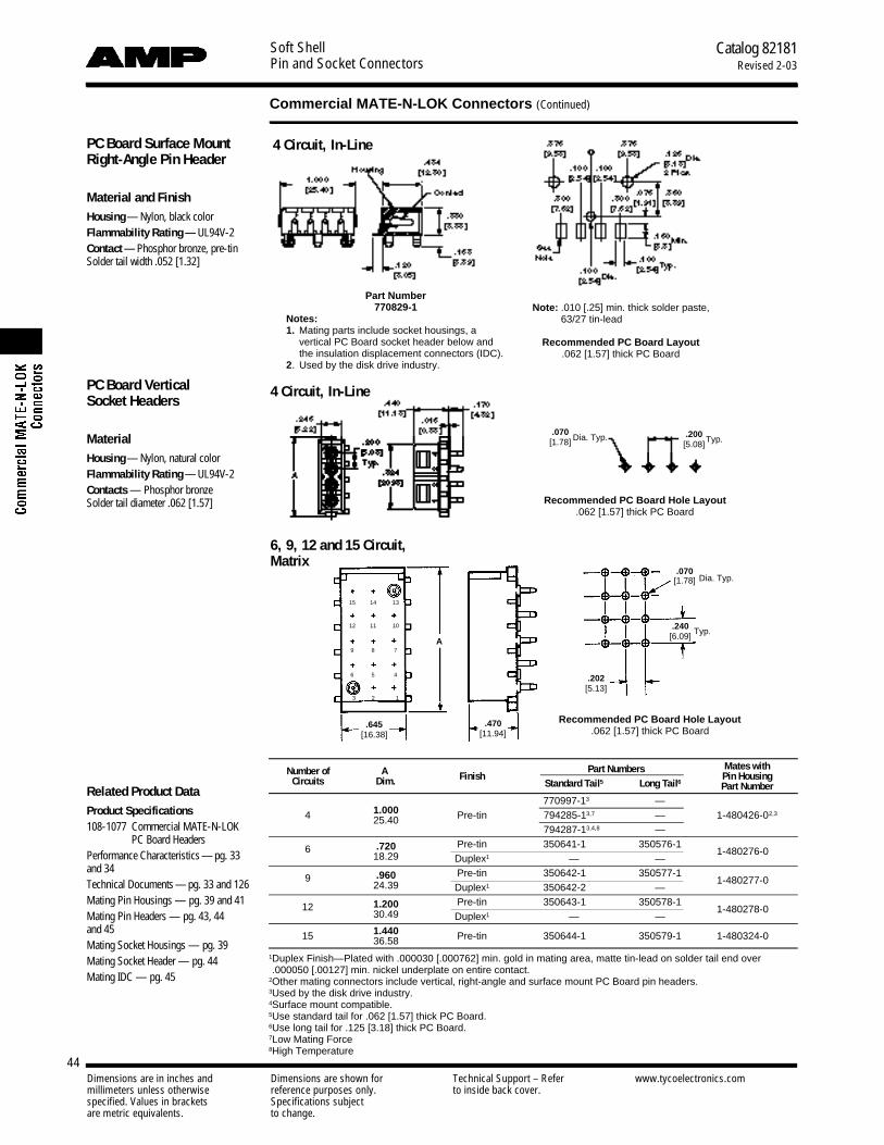
Soft ShellPin and Socket Connectors
Catalog 82181Revised 2-03
44
Commercial MATE-N-LOK Connectors (Continued)
Dimensions are in inches and Dimensions are shown for Technical Support – Refer www.tycoelectronics.commillimeters unless otherwise reference purposes only. to inside back cover.specified. Values in brackets Specifications subjectare metric equivalents. to change.
Note: .010 [.25] min. thick solder paste, 63/27 tin-lead
Recommended PC Board Layout.062 [1.57] thick PC Board
6, 9, 12 and 15 Circuit,Matrix
Recommended PC Board Hole Layout.062 [1.57] thick PC Board
Number of A Part Numbers Mates withFinish Pin HousingCircuits Dim. Standard Tail5 Long Tail6 Part Number
1.000770997-13,4,7,9 —
4 Pre-tin 794285-13,7.3 — 1-480426-02,325.40
794287-13,4,8,7,9 —
6 .720 Pre-tin 350641-13,4,7,3 350576-11-480276-02,3
18.29 Duplex1 — —
9 .960 Pre-tin 350642-13,4,7,9 350577-11-480277-02,3
24.39 Duplex1 350642-23,4,7,9 —
12 1.200 Pre-tin 350643-13,4,7,9 350578-11-480278-02,3
30.49 Duplex1 — —
15 1.440 Pre-tin 350644-13,4,7,9
350579-1 1-480324-02,336.58
1Duplex Finish—Plated with .000030 [.000762] min. gold in mating area, matte tin-lead on solder tail end over.000050 [.00127] min. nickel underplate on entire contact.
2Other mating connectors include vertical, right-angle and surface mount PC Board pin headers.3Used by the disk drive industry.4Surface mount compatible.5Use standard tail for .062 [1.57] thick PC Board.6Use long tail for .125 [3.18] thick PC Board.7Low Mating Force8High Temperature
15 14 13
12 11 10
9 8 7
6 5 4
3 2 1
.645[16.38]
.470[11.94]
Typ.
Dia. Typ.
.240[6.09]
.202[5.13]
.070[1.78]
Related Product DataProduct Specifications108-1077 Commercial MATE-N-LOK
PC Board HeadersPerformance Characteristics — pg. 33and 34Technical Documents — pg. 33 and 126Mating Pin Housings — pg. 39 and 41Mating Pin Headers — pg. 43, 44and 45Mating Socket Housings — pg. 39Mating Socket Header — pg. 44Mating IDC — pg. 45
PC Board Surface Mount Right-Angle Pin Header
Material and FinishHousing — Nylon, black colorFlammability Rating — UL94V-2Contact — Phosphor bronze, pre-tinSolder tail width .052 [1.32]
A
4 Circuit, In-Line
Part Number770829-1
Notes:1. Mating parts include socket housings, a
vertical PC Board socket header below andthe insulation displacement connectors (IDC).
2. Used by the disk drive industry.
.200[5.08]
4 Circuit, In-LinePC Board Vertical Socket Headers
MaterialHousing — Nylon, natural colorFlammability Rating — UL94V-2Contacts — Phosphor bronzeSolder tail diameter .062 [1.57] Recommended PC Board Hole Layout
.062 [1.57] thick PC Board
.070[1.78] Dia. Typ. Typ.

Soft ShellPin and Socket Connectors
Catalog 82181Revised 2-03
45
Commercial MATE-N-LOK Connectors (Continued)
Dimensions are in inches and Dimensions are shown for Technical Support – Refer www.tycoelectronics.commillimeters unless otherwise reference purposes only. to inside back cover.specified. Values in brackets Specifications subjectare metric equivalents. to change.
.505[12.82]
Dust Covers
MaterialHousing— Polyester, white color
Flammability Rating — UL94V-2
PC Board Right-AnglePin Headers
Material and FinishContact — Phosphor bronze, pre-tinSolder tail width .052 [1.32]
For Feed-To WiringPart Number 770232-1
Socket Assembly (Plug)
4 Circuit, In-Line
For Feed-Through WiringPart Number 770233-1
Wire Size Range Color FinishPart Number Mates with
AWG [mm2] Code UL94V-2 UL94V-0 Part Numbers
22 Red Pre-tin 770156-2* 794036-3 1-480426-0**[.3] 1-350211-12
20 Yellow Pre-tin 770156-4* 794036-2 1-350211-22
[.5] 1-350424-12
18 Orange Pre-tin 770156-3* 794036-11-350424-22
[.8] 1-641737-12
16
1-641737-12
1-770827-12
[1.2] Blue Pre-tin 770156-5* 794036-4 1-770829-12
1-770846-12
*Application Tooling: Arbor Tool 91085-2 uses head 231920-2.**Pin HousingNotes:1. Insulation diameter .095 [2.41] max.2. Application Tooling
Power Unit No. 9 1 1 1 2 - 2 (IS 408-7763) uses Head No. 2 3 1 9 2 0 - 2 (IS 408-9330) and Hand Tool Handle No. 5 8 0 7 4 - 1(IS 408-6790) uses Head No. 231894-1(IS 408-3186)
.994[25.24]
.325[8.25]
Max.
.142[3.60]
Max.
Max.
.390[9.90]
.200[5.08]
.830[21.08]Max.
.643[16.33]Max.
.760[19.30]
.760[19.30]
Insulation DisplacementConnectors (IDC)
MaterialHousing — NylonContact — Phosphor bronze
Related Product DataUsed by the disk drive industry.
Product Specifications108-1077 Commercial MATE-N-LOK
PC Board Headers108-49000 IDC Connectors
Application Specification114-49001 IDC ConnectorsPerformance Characteristics — pg. 33and 34Technical Documents — pg. 33 and 126Mating Socket Housings — pg. 39Mating Pin Housings — pg. 39, 41Mating Pin Headers — pg. 43, 44and 45
Recommended PC Board Hole Layout.062 [1.57] thick PC Board
Number of Dimensions Part Mates withHousing Material Socket HousingCircuits A B C D Numbers Part Number
2 .600 — .300 — UL94V-2 Nylon 794120-1 1-480318-015.24 7.62 Natural Color
3 .800 .150 .300 .600 UL94V-0 Nylon 643488-11,3
1-480303-020.32 3.81 7.62 15.24
4
UL94V-2 Nylon, 641737-13,11-480424-02,3
1.000 .200 .400 .800 Natural Color 770846-11,3
25.40 5.08 10.16 20.32UL94V-0 Nylon 1-641737-13 770827-12,3
1Surface Mount Compatible. 2Other mating connectors include a vertical PC Board socket header and the insulationdisplacement connectors (IDC). 3Used by the disk drive industry.
.345[.876]
.400[10.16]
.100[2.54]
.100[2.54]
.484[12.29]
.140[3.55]
Typ.
Dia.
Dia.
Dia..200
[5.08]Typ.
A
D
BC
.060[1.524]
(4 Plcs.)
.100[2.54]
(2 Plcs.)
.157[3.98]
(2 Plcs.)
Note: These parts are used with the insulation displacement connectors below.
.142[3.60]Max.
Max..505[12.82]
2, 3, and 4 Circuit, In-Line 2, 3, and 4 Circuit

Soft ShellPin and Socket Connectors
Catalog 82181Revised 2-03
46
Commercial MATE-N-LOK Connectors (Continued)
Dimensions are in inches and Dimensions are shown for Technical Support – Refer www.tycoelectronics.commillimeters unless otherwise reference purposes only. to inside back cover.specified. Values in brackets Specifications subjectare metric equivalents. to change.
PC Board Edge Mount Pin HeadersMaterialHousing — Thermoplastic, black colorFlammability Rating — UL94V-0Contacts — Pre-tin Copper Alloy
Related Product DataUsed by the disk drive industry
Product Specification108-5155-5Mating Socket Housing — pg. 39Mating Socket Header — pg. 44Mating IDC — pg. 45
Part No. 175332-2 Part No. 175332-3
Notes: Mates with socket housing Part No. 1-480424-0. Other mating connectors include a vertical PC Board socketheader and the insulation displacement connectors (IDC). Molded ribs provide interference for .057 [1.45] to .067 [1.70].
4 Circuit, In-Line
PC Board Right-Angle Mid Mount Pin HeaderAssemblyReverse PlugSide GuidedMaterialHousing — NylonFlammability Rating — UL94V-0Contacts — Pre-tin, Phosphor Bronze
Related Product DataUsed by the disk drive industryMating Socket Housing — pg. 39Mating Socket Header — pg. 44Mating IDC — pg. 45
Part No.84069-1
Recommended PC Board Hole Layout.047 [1.20] thick PC Board
Notes: Mates with socket housing Part No. 1-480424-0. Other mating connectors include a vertical PC Board socketheader and the insulation displacement connectors (IDC).
4 Circuit, In-Line
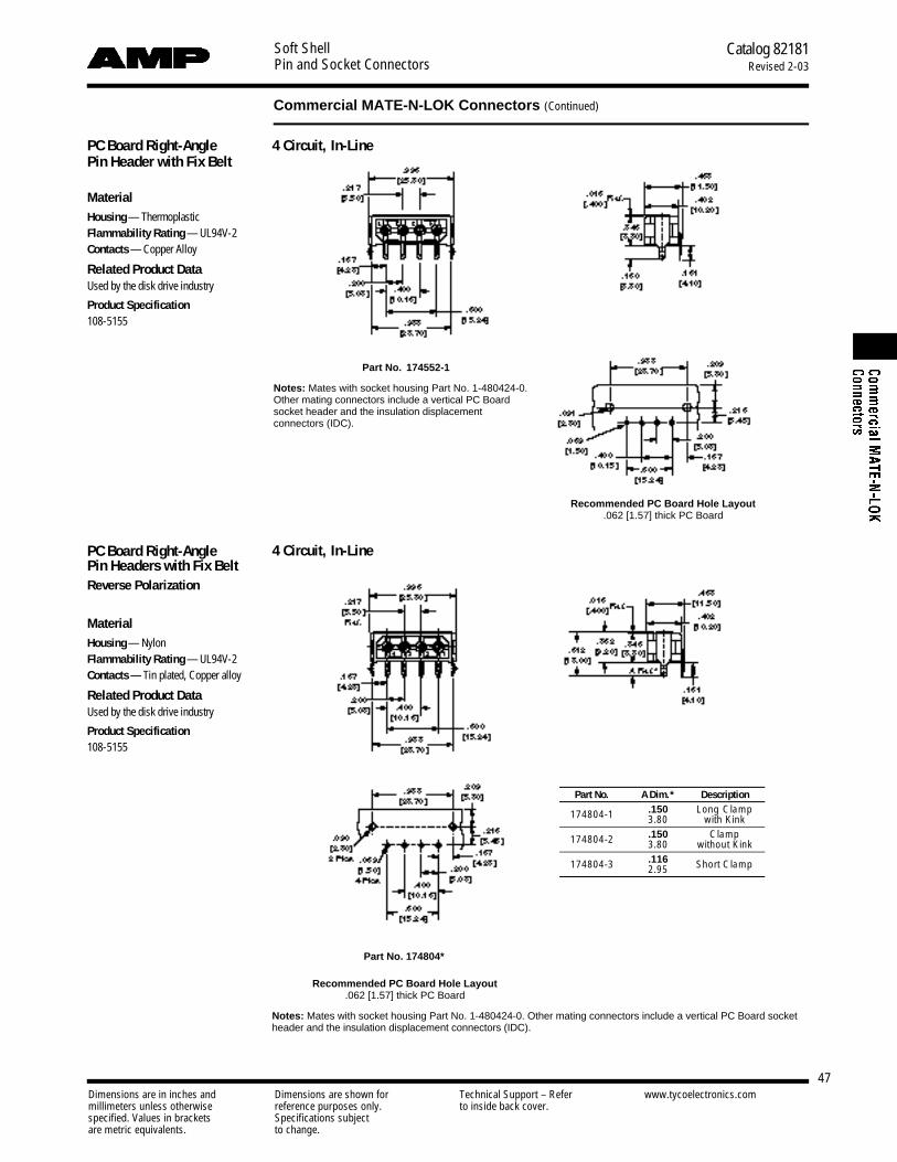
Soft ShellPin and Socket Connectors
Catalog 82181Revised 2-03
47
Commercial MATE-N-LOK Connectors (Continued)
Dimensions are in inches and Dimensions are shown for Technical Support – Refer www.tycoelectronics.commillimeters unless otherwise reference purposes only. to inside back cover.specified. Values in brackets Specifications subjectare metric equivalents. to change.
PC Board Right-Angle Pin Header with Fix Belt
MaterialHousing — ThermoplasticFlammability Rating — UL94V-2Contacts — Copper Alloy
Related Product DataUsed by the disk drive industry
Product Specification108-5155
Part No. 174552-1
Notes: Mates with socket housing Part No. 1-480424-0.Other mating connectors include a vertical PC Boardsocket header and the insulation displacement connectors (IDC).
Recommended PC Board Hole Layout.062 [1.57] thick PC Board
4 Circuit, In-Line
PC Board Right-Angle Pin Headers with Fix BeltReverse Polarization
MaterialHousing — NylonFlammability Rating — UL94V-2Contacts — Tin plated, Copper alloy
Related Product DataUsed by the disk drive industry
Product Specification108-5155
Part No. 174804*
Recommended PC Board Hole Layout.062 [1.57] thick PC Board
Notes: Mates with socket housing Part No. 1-480424-0. Other mating connectors include a vertical PC Board socketheader and the insulation displacement connectors (IDC).
Part No. A Dim.* Description
174804-1 .150 Long Clamp3.80 with Kink
174804-2 .150 Clamp3.80 without Kink
174804-3 .116 Short Clamp2.95
4 Circuit, In-Line
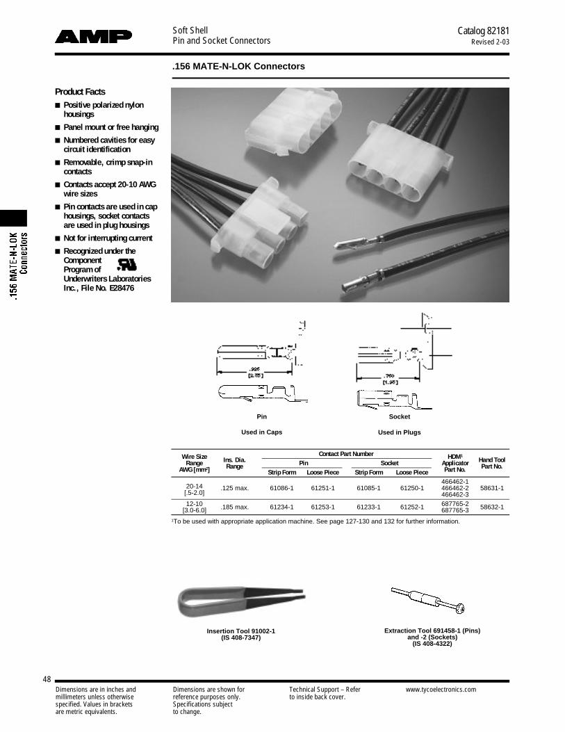
Soft ShellPin and Socket Connectors
Catalog 82181Revised 2-03
48Dimensions are in inches and Dimensions are shown for Technical Support – Refer www.tycoelectronics.commillimeters unless otherwise reference purposes only. to inside back cover.specified. Values in brackets Specifications subjectare metric equivalents. to change.
.156 MATE-N-LOK Connectors
Product Facts■ Positive polarized nylon
h o u s i n g s
■ Panel mount or free hanging
■ Numbered cavities for easycircuit identification
■ Removable, crimp snap-inc o n t a c t s
■ Contacts accept 20-10 AWGwire sizes
■ Pin contacts are used in caphousings, socket contactsare used in plug housings
■ Not for interrupting current
■ Recognized under theComponent Program of Underwriters LaboratoriesInc., File No. E28476
Wire Size Ins. Dia.Contact Part Number HDM1
Hand ToolRange Pin Socket ApplicatorAWG [mm2] Range
Strip Form Loose Piece Strip Form Loose Piece Part No. Part No.
20-14466462-1
[.5-2.0].125 max. 61086-1 61251-1 61085-1 61250-1 466462-2 58631-1
466462-312-10 .185 max. 61234-1 61253-1 61233-1 61252-1 687765-2 58632-1[3.0-6.0] 687765-3
1To be used with appropriate application machine. See page 127-130 and 132 for further information.
Pin
Used in Caps
Socket
Used in Plugs
Insertion Tool 91002-1(IS 408-7347)
Extraction Tool 691458-1 (Pins)and -2 (Sockets)
(IS 408-4322)

Soft ShellPin and Socket Connectors
49Dimensions are in inches and Dimensions are shown for Technical Support – Refer www.tycoelectronics.commillimeters unless otherwise reference purposes only. to inside back cover.specified. Values in brackets Specifications subjectare metric equivalents. to change.
Catalog 82181Revised 2-03
.156 MATE-N-LOK Connectors (Continued)
Pin Housing (Cap)Free Hanging
Part Number 794117-1
Pin Housing (Cap)Panel Mount
Part Number 794118-1
Socket Housing (Plug)Part Number 794116-1
Panel Mount Cutout
Related Product DataProduct Specification108-8002
Application Specification114-1109
ContactsPin diameter .156 [3.96]
Material and FinishContacts — Brass, Pre-tin platedStock thickness .018 [.457]
Housings — Nylon, Natural ColorFlammability Rating — UL94V-2
Number of A CapCircuits Dim. Plug
Free Hanging Panel Mount
3 .048 794412-1 794413-1 —1.210
4 .063 794116-1 794117-1 794118-11.600
Note: Panel must be punched in the same direction as the housing will be inserted.

Soft ShellPin and Socket Connectors
Catalog 82181Revised 2-03
50
.140 MATE-N-LOK Connectors (Large Insulation), .240 Centerline
Dimensions are in inches and Dimensions are shown for Technical Support – Refer www.tycoelectronics.commillimeters unless otherwise reference purposes only. to inside back cover.specified. Values in brackets Specifications subjectare metric equivalents. to change.
Product Facts■ Available in 2, 3 and 9 cir-
cuit configurations for panelmounting; 4 and 9 circuitconfigurations for freehanging applications
■ Standard natural nylonhousings
■ Housings fully polarized
■ Contacts fully protected inhousings
■ Contacts accept wire sizerange 20-10 AWG [.5-5.0mm2] with insulation diam-eters from .100 [2.54] to.180 [4.57]
■ Low insertion/extractionforces
■ Dual locking lances provideoptimum contact stability
■ Extraction tool removesboth pins and sockets
■ Contacts are on .240 [6.09]centerline spacing
■ Not for interrupting current
■ Recognized under theComponent Program of Underwriters LaboratoriesInc., File No. E28476
■ Certified by CanadianStandards Association,File No. LR 7189A
Performance CharacteristicsThe .140 MATE-N-LOK Connector per-formance characteristics found on thispage are based on free hanging andpanel mount connectors, loaded withcontacts crimped on stranded wire.
Dielectric Withstand Voltage3.0 KVAC between adjacent circuits
Insulation Resistance1000 megohms minimum initial betweenadjacent circuits
Voltage Rating 250 V AC or DC
Connector Mating 4.5 lb. max. percircuit
Connector Unmating .8 lb. min. percircuit
Contact Retention 30 lb. min.
Durability 25 cycles, mating and unmating
Thermal Shock 255°C to +85°C
Temperature-Humidity Cycling25°C to 65°C at 95 RH
Termination ContactResistance Crimp
Wire SizeTest Resistance
Tensile ForceAWG mm2
Current Milliohms Force (Min.)(Amps) (Max. Init.) lbs. N
20 .5 4.5 3.0 20 8918 .8 6 2.5 30 13316 1.2 8 2.5 45 20014 2.0 10 2.0 50 22212 3.0 12 1.5 60 26710 5.0 14 1.5 65 289
N o t e: This is the total resistance between wire crimps of a mated pin and socket.
Maximum Current Maximum currentrating of .140 MATE-N-LOK connectorsis limited by the maximum operatingtemperature of the housings which is105°C and the temperature rise of thecontacts which is 30°C. There are sev-eral variables which have a direct effecton this maximum current-carrying capa-bility for a given connector and must beconsidered for each application. Thesevariables are:
Wire Size Larger diameter wire willcarry more current since it has less in-ternal resistance to current flow and thusgenerates less heat. Longer wire lengthsalso enhance current-carrying capabili-ties since the wire conducts heat awayfrom the connector.
Connector Size In general, the morecircuits in a connector, the less currentcan be carried.
Ambient Temperature The higherthe ambient temperature, the less currentcan be carried in any given connector.
Technical DocumentsProduct Specification108-1032 .140 Diameter
MATE-N-LOK Connectors
Application Specification114-1007 .140 Diameter
MATE-N-LOK Contacts
Current Rating Verification for 308C Maximum Temperature Rise100% Energized
Wire-to-Wire.140 MATE-N-LOK Connector Calculated Current Table
Number of Wire AWGCircuits 10 12 14 16 18 20
2 28.00 23.00 18.50 15.00 13.50 10.503 25.00 21.00 17.00 13.50 12.00 9.509 18.50 15.00 12.00 10.00 9.00 7.00
Values are based on initial Temperature Rise versus Current Testing and areintended to be a guide in the selection of a connector family. All applicationsshould be tested by the end user. The values listed are per circuit for fullyloaded housings being 100% energized. Note: All combinations were nottested, and this chart contains interpolated and extrapolated values.
Minimum Wire Lengths for T-Rise vs. Current TestingNote: If wire lengths used are less than those listed, the current carrying ability of the system will be reduced due to less heat being conducted awayfrom the connector. The customer should fully test all applications.

Soft ShellPin and Socket Connectors
Catalog 82181Revised 2-03
51
.140 MATE-N-LOK Connectors (Large Insulation), .240 Centerline (Continued)
Dimensions are in inches and Dimensions are shown for Technical Support – Refer www.tycoelectronics.commillimeters unless otherwise reference purposes only. to inside back cover.specified. Values in brackets Specifications subjectare metric equivalents. to change.
Contact Extraction ToolPart No. 453300-1
IS 408-9569
Socket Housing (Plug)Part No. 1-480585-0
Socket Housing (Plug)Part No. 1-480510-0
Pin Housing (Cap)Part No. 1-480586-0
Pin Housing (Cap)Part No. 1-480512-0
Part No. 794700-1 (Black Color High Temp.)
ContactsPin diameter .140 [3.57]Stock thickness .014 [.357]
Related Product DataProduct Specification108-1032 .140 Diameter
MATE-N-LOK ConnectorsApplication Specification114-1007 .140 Diameter
MATE-N-LOK Contacts
Performance Characteristics — pg. 50Keying Plug — noneHousings — pg. 51 and 52Technical Documents — pg. 50 and 126Application Tooling — pg. 127-130 and132
HousingsFree Hanging.240 [6.09] Centerline spacing
MaterialNylon, natural color
Flammability Rating — UL94V-2
Cavity Identification(Rear View)
Pin
Cap
Cap
Plug
Plug
Socket
9 Circuit, Matrix
4 Circuit
Wire Size Ins. Dia.Contact Part Numbers HDM Hand ToolRange
RangeMaterial & Finish Pin Socket Applicator Part No.
AWG [mm2] Strip Form Loose Form Strip Form Loose Form Part No.
20-14 .100-.180 Brass. pre-tin 61627-1 350389-1 61626-1 350388-1 567306-1567306-2 91552-1[.5-2.0] 2.54-4.5 Phos. Brz., pre-tin 61627-2 — 61626-2 — 567306-3
14-10 .100-.180 Brass. pre-tin 350201-1 350391-1 350200-1 350390-1 567309-1567309-2 69710-12
[2.0-5.0] 2.54-4.5 Phos. Brz., pre-tin 350201-2 350391-2 350200-2 350390-2 567309-31HDM Applicator part number ending in -1 is used on AMPOMATOR CLS Machine with T or G Terminators, -2 is usedon AMP-O-LECTRIC Model K Machine, -3 is used on AMP-O-LECTRIC Model G Machine. See page 132 for furtherinformation.
2Hand Tool No. 69710-1 uses die set No. 58374-1 for 14-12 AWG and No. 58373-1 for 10 AWG.
.995[25.27]
1.130[28.70]
1.065[27.05]
.865[21.97]
1.130[28.70]
.755[19.17]
.755[19.17]
.755[19.17]
.845[21.46]
.845[21.46]
.240[6.09]
.240[6.09]
.240[6.09]
.240[6.09]
1.180[29.97]
.775[19.68]
.580[14.73]
.950[24.13]
.950[24.13]
1.350[34.29]
.565[14.35]
.795[20.19]

Soft ShellPin and Socket Connectors
Catalog 82181Revised 2-03
52
.140 MATE-N-LOK Connectors (Large Insulation), .240 Centerline (Continued)
Dimensions are in inches and Dimensions are shown for Technical Support – Refer www.tycoelectronics.commillimeters unless otherwise reference purposes only. to inside back cover.specified. Values in brackets Specifications subjectare metric equivalents. to change.
HousingsPanel Mount.240 [6.09] Centerline spacing
MaterialHousing — Nylon, natural color
Flammability Rating — UL94V-2
Cavity Identification(Rear View)
2 and 3 Circuit, In-Line
Socket Housing (Plug)Part No. 1-350344-0
Part No. 794699-1 (Black Color High Temp.)
Socket Housing (Plug)Part No. 1-350346-0
Socket Housing (Plug)Part No. 1-480672-0
Pin Housing (Cap)Part No. 1-350345-0
Pin Housing (Cap)Part No. 1-350347-0
Part No. 794061-1 (Black Color High Temp.)
Pin Housing (Cap)Part No. 1-480673-0
Part No. 794683-1 (Black Color High Temp.)
Plug
Plug
Plug
Cap
Cap
Cap
Related Product DataProduct Specification108-1032 .140 Diameter
MATE-N-LOK ConnectorsApplication Specification114-1007 .140 Diameter
MATE-N-LOK Contacts
Performance Characteristics — pg. 50Keying Plug — noneContacts — pg. 51Technical Documents — pg. 50 and 126
Notes:1. Panel thickness .040-.070
[1.02-1.78].2. "X" and "Y" dimensions must
be within .005 [.127] of eachother.
3. Panel should be punched sothat the housing enters thepanel in the same direction asthe punch for ease of assembly.
12 Circuit-.725 [18.42]3 Circuit- .965 [24.51]
2.050 x .050 [1.27-1.27] tabs in corners ofoutlet are optional to reduce housingfloat in panel.
.515[13.08]
.950[24.13]
.950[24.13]
.950[24.13]
.950[24.13]
.910[23.11]
.755[19.17]
.755[19.17]
.765[19.43]
.765[19.43]
.755[19.17]
.755[19.17]
.815[20.70]
.275[6.98]
.275[6.98]
1.055[26.79]
1.205[26.79]
.240[6.09]
.240[6.09]
.240[6.09]
.240[6.09]
.288[7.31]
.0502
[1.27]
.0502
[1.27]
1.025[26.03]
1.025[26.03]
.475[12.06]
.910[23.11]
.190[4.82]
.190[4.82]
.240[6.09]
.240[6.09]
.965[24.51]
.365[9.27]
.365[9.27]
1.130[28.70]
1.130[28.70]
1.130[28.70]
.515[13.08]
C1
X
X
Y
Recommended Panel CutoutsView is from housing entry side
9 Circuit, Matrix
2 and 3 Circuit 9 Circuit

Soft ShellPin and Socket Connectors
Catalog 82181Revised 2-03
53
.093 [2.36] Commercial Pin and Socket Connectors
Dimensions are in inches and Dimensions are shown for Technical Support – Refer www.tycoelectronics.commillimeters unless otherwise reference purposes only. to inside back cover.specified. Values in brackets Specifications subjectare metric equivalents. to change.
Product Facts■ Polarized
■ Cavity identification
■ Low contact-mating force
■ Dual locking lances
■ Detent and positive locking
■ Contacts available in brassand phosphor bronze withtin and gold plating
■ Panel mounting and freehanging styles
■ “F” crimp contacts
■ Applicator and hand toolavailable
■ Economical commercial-grade connectors
■ Compatible with high-speedapplication machinery andcompetitive soft shells
■ Wire range 24 to 14 AWG[0.2 to 2 mm2]
■ Accepts wires with insula-tion diameters as large as.180 [4.57]
■ Housings available in 1 to15 positions
■ .093 plug and receptaclehousings accept pin orsocket contacts. The pre-ferred convention is to usesocket contacts with recep-tacle housings
■ Not for interrupting current
■ Recognized under theComponent Program ofUnderwriters Laboratories Inc.,File No. E28476
■ Certified by CanadianStandards Association, File No. LR 7189
Performance CharacteristicsThe .093 Commercial Pin and SocketConnectors performance characteristicsfound on pages 53 and 54 are based onfree hanging and panel mount connec-tors, loaded with contacts crimped onstranded wire.
Thermal Shock -55°C to +105°C
Temperature-Humidity Cycling+25°C to +65°C at 90–95% RH
Corrosion 48 hr. at 5% salt concentration
Vibration 10-55-10 cycles per minuteat .06 [1.52] total excursion
Physical Shock 18 shocks, 50 Gssawtooth in 11 milliseconds
Durability 50 mating cycles
Dielectric Withstanding Voltage1.0 kVAC
Insulation Resistance 1000megohms min. initial
Voltage Rating 250 V AC or DC
Connector Mating 2.5 lb. [11.1 N]max. per contact
Connector Unmating 1.5 lb. [6.7 N]min. per contact
Contact Retention10 lb. [44.5 N] min.
Technical DocumentsApplication Specification114-49000 .093 Commercial Pin andSocket Connectors
Product Specification108-1038 .093 Commercial Pin andSocket Connectors
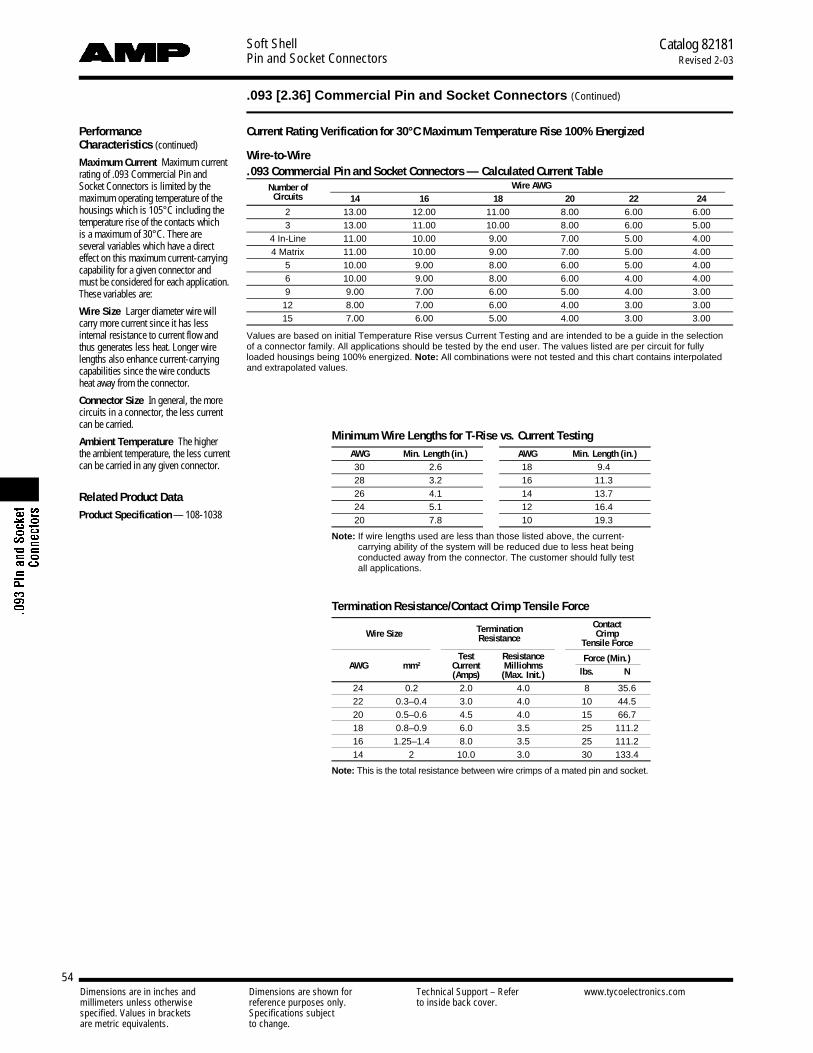
Soft ShellPin and Socket Connectors
Catalog 82181Revised 2-03
54
.093 [2.36] Commercial Pin and Socket Connectors (Continued)
Dimensions are in inches and Dimensions are shown for Technical Support – Refer www.tycoelectronics.commillimeters unless otherwise reference purposes only. to inside back cover.specified. Values in brackets Specifications subjectare metric equivalents. to change.
Performance Characteristics (continued)
Maximum Current Maximum currentrating of .093 Commercial Pin andSocket Connectors is limited by themaximum operating temperature of thehousings which is 105°C including thetemperature rise of the contacts which is a maximum of 30°C. There are several variables which have a direct effect on this maximum current-carryingcapability for a given connector andmust be considered for each application.These variables are:
Wire Size Larger diameter wire willcarry more current since it has less internal resistance to current flow andthus generates less heat. Longer wirelengths also enhance current-carryingcapabilities since the wire conducts heat away from the connector.
Connector Size In general, the morecircuits in a connector, the less currentcan be carried.
Ambient Temperature The higherthe ambient temperature, the less currentcan be carried in any given connector.
Related Product DataProduct Specification — 108-1038
Termination ContactWire Size CrimpResistance Tensile Force
Test Resistance Force (Min.)AWG mm2 Current Milliohms
(Amps) (Max. Init.) lbs. N
24 0.2 2.0 4.0 8 35.622 0.3–0.4 3.0 4.0 10 44.520 0.5–0.6 4.5 4.0 15 66.718 0.8–0.9 6.0 3.5 25 111.216 1.25–1.4 8.0 3.5 25 111.214 2 10.0 3.0 30 133.4
N o t e : This is the total resistance between wire crimps of a mated pin and socket.
Current Rating Verification for 30°C Maximum Temperature Rise 100% Energized
Wire-to-Wire.093 Commercial Pin and Socket Connectors — Calculated Current Table
Number of Wire AWGCircuits 14 16 18 20 22 24
2 13.00 12.00 11.00 8.00 6.00 6.003 13.00 11.00 10.00 8.00 6.00 5.00
4 In-Line 11.00 10.00 9.00 7.00 5.00 4.004 Matrix 11.00 10.00 9.00 7.00 5.00 4.00
5 10.00 9.00 8.00 6.00 5.00 4.006 10.00 9.00 8.00 6.00 4.00 4.009 9.00 7.00 6.00 5.00 4.00 3.00
12 8.00 7.00 6.00 4.00 3.00 3.0015 7.00 6.00 5.00 4.00 3.00 3.00
Values are based on initial Temperature Rise versus Current Testing and are intended to be a guide in the selectionof a connector family. All applications should be tested by the end user. The values listed are per circuit for fullyloaded housings being 100% energized. Note: All combinations were not tested and this chart contains interpolatedand extrapolated values.
Termination Resistance/Contact Crimp Tensile Force
Minimum Wire Lengths for T-Rise vs. Current TestingAWG Min. Length (in.) AWG Min. Length (in.)30 2.6 18 9.428 3.2 16 11.326 4.1 14 13.724 5.1 12 16.420 7.8 10 19.3
Note: If wire lengths used are less than those listed above, the current-carrying ability of the system will be reduced due to less heat beingconducted away from the connector. The customer should fully test all applications.
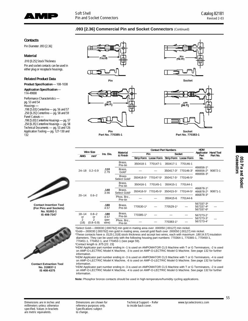
Soft ShellPin and Socket Connectors
Catalog 82181Revised 2-03
55
.093 [2.36] Commercial Pin and Socket Connectors (Continued)
Dimensions are in inches and Dimensions are shown for Technical Support – Refer www.tycoelectronics.commillimeters unless otherwise reference purposes only. to inside back cover.specified. Values in brackets Specifications subjectare metric equivalents. to change.
ContactsPin Diameter .093 [2.36]
Material.010 [0.25] Stock ThicknessPin and socket contacts can be used ineither plug or receptacle housings.
Related Product DataProduct Specification — 108-1038
Application Specification —114-49000
Performance Characteristics —pg. 53 and 54Housings —.198 [5.03] Centerline— pg. 56 and 57.250 [6.35] Centerline— pg. 58 and 59Panel Cutouts —.198 [5.03] Centerline Housings— pg. 57.250 [6.35] Centerline Housings— pg. 58Technical Documents — pg. 53 and 126Application Tooling — pg. 127-130 and132
Pin Socket
PinPart No. 770385-1
SocketPart No. 770383-1
Contact Insertion Tool(For Pins and Sockets)
No. 91002-1IS 408-7347
Contact Part Numbers HDMWire Size
Ins. Dia. Material Pin Socket Applicator Hand ToolAWG mm2 & Finish Part Part No.
Strip Form Loose Form Strip Form Loose Form No.Brass,Pre-tin 350418-1 770147-1 350417-1 770146-1
466656-15
24–18 0.2–0.9 .110 Brass,2.79 Gold2 — — 350417-32 770146-32 466656-25 90872-1
BrassSelect Gold1 350418-51 770147-51 350417-51 770146-51
466656-35
Brass,Pre-tin 350416-1 770145-1 350415-1 770144-1
466878-15.140 Brass,3.56 Select Gold1 350416-51 770145-51 350415-51 770144-51 466878-25 90871-1
20–14 0.6–2 Phos. Brz.,Pre-tin — — 350415-6 770144-6
466878-35
.180 Brass, 567337-36
770530-14 — 770529-14 — 567337-46 —4.57 Pre-tin 567337-66
18–14 0.8–2 .180 Brass,567273-27
or or 4.57 Pre-tin 770385-13 — — —
2 2 (per Phos. Brz.,567273-37 —
(18) (0.8–0.9) wire) Pre-tin — — 770383-13 — 567273-47
1Select Gold—.000030 [.000762] min gold in mating area over .000050 [.00127] min nickel.2Gold—.000030 [.000762] min gold in mating area, overall gold flash over .000050 [.00127] min nickel.3These contacts have a .0125 [.318] stock thickness and accept two wires, each with maximum .180 [4.57] insulationdiameters. They can be used only with the following housing part numbers: 770364-1, 770365-1, 770450-1, 770451-1, 770452-1, and 770453-1 (see page 59).
4Contact length is .875 [22. 23]5HDM Applicator part number ending in -1 is used on AMPOMATOR CLS Machine with T or G Terminators, -2 is usedon AMP-O-LECTRIC Model K Machine, -3 is used on AMP-O-LECTRIC Model G Machine. See page 132 for furtherinformation.
6HDM Applicator part number ending in -3 is used on AMPOMATOR CLS Machine with T or G Terminators, -4 is usedon AMP-O-LECTRIC Model K Machine, -6 is used on AMP-O-LECTRIC Model G Machine. See page 132 for furtherinformation.
7HDM Applicator part number ending in -3 is used on AMPOMATOR CLS Machine with T or G Terminators, -2 is usedon AMP-O-LECTRIC Model K Machine, -4 is used on AMP-O-LECTRIC Model G Machine. See page 132 for furtherinformation.
Note: Phosphor bronze contacts should be used in high-temperature/humidity cycling applications.
Contact Extraction ToolNo. 318837-1IS 408-4375

Soft ShellPin and Socket Connectors
Catalog 82181Revised 2-03
56
.093 [2.36] Commercial Pin and Socket Connectors (Continued)
Dimensions are in inches and Dimensions are shown for Technical Support – Refer www.tycoelectronics.commillimeters unless otherwise reference purposes only. to inside back cover.specified. Values in brackets Specifications subjectare metric equivalents. to change.
HousingsFree Hanging or Panel Mount.198 [5.03] Centerline spacing
MaterialHousing— Nylon, natural colorFlammability Rating —UL94V-2
Related Product Data
Contacts — pg. 55
Product Specification — 108-1038
Receptacle Plug
Receptacle Plug
2, 3, and 4 Circuit, In-Line
Receptacle Part NumbersPlug Part Numbers
No. of A Dimension Panel Mount Free HangingCircuits Receptacle Plug Without With Without With
Panel Free
Detents Detents Detents DetentsMount Hanging
1 — — — — — 770063-1 — 770064-1.540 .640 770065-11,5
2 13.72 16.26 — 770066-11,5 — 7702661,3,5 770068-11 770069-11
.670 .770 770070-13 17.02 19.56 — 770071-1 — 770264-13 770073-12 770074-1
4 .870 .970(In-Line) 22.10 24.64 — 770076-1 — 770075-1 770077-12 770078-1
4 .443 .540(Matrix) 11.25 13.71 — — — 770843-1 — 770842-1
1.070 1.170 770083-15 27.18 29.72 — — — 794015-13 — 770084-1
6 1.268 1.378(In-Line) 32.21 35.00 — — — 770782-14 — 770892-14
6 .435 .535(Matrix) 11.05 13.59 770085-1 770087-1 770088-1 770086-1 770089-12 770090-1
.670 .770 770092-1 770095-129 17.02 19.56 770091-1 770093-1 770094-1 770108-12 770096-1
.870 .97012 22.10 24.64 770097-1 770099-1 770100-1 770098-1 770101-12 770102-1
1.070 1.17015 27.18 29.72 770103-1 — 770105-1 — 770106-12 770107-1
1.248 [6.30] centerline.2Mounting ears at wire end.3Tool removable.4Positive lock.5600 V AC or DC
1 Circuit
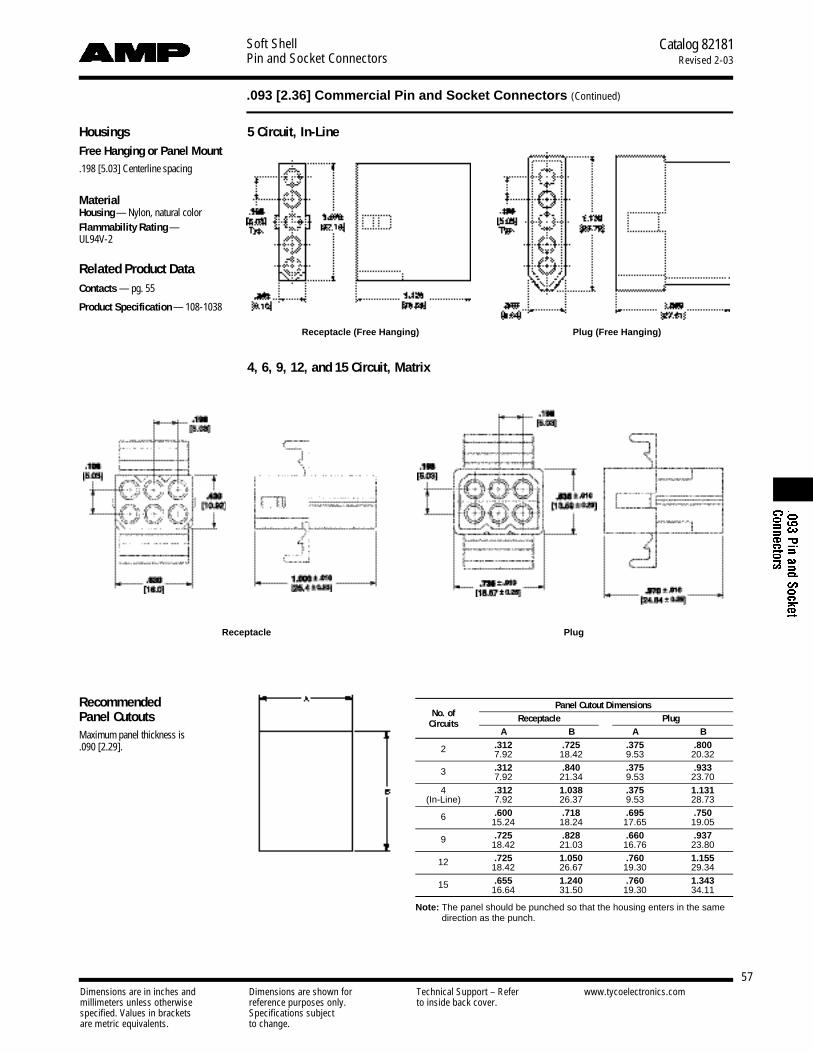
Soft ShellPin and Socket Connectors
Catalog 82181Revised 2-03
57
.093 [2.36] Commercial Pin and Socket Connectors (Continued)
Dimensions are in inches and Dimensions are shown for Technical Support – Refer www.tycoelectronics.commillimeters unless otherwise reference purposes only. to inside back cover.specified. Values in brackets Specifications subjectare metric equivalents. to change.
HousingsFree Hanging or Panel Mount.198 [5.03] Centerline spacing
MaterialHousing— Nylon, natural colorFlammability Rating —UL94V-2
Related Product DataContacts — pg. 55
Product Specification — 108-1038
Receptacle (Free Hanging) Plug (Free Hanging)
4, 6, 9, 12, and 15 Circuit, Matrix
Receptacle Plug
Panel Cutout DimensionsNo. of Receptacle PlugCircuits
A B A B.312 .725 .375 .8002 7.92 18.42 9.53 20.32.312 .840 .375 .9333 7.92 21.34 9.53 23.70
4 .312 1.038 .375 1.131(In-Line) 7.92 26.37 9.53 28.73
.600 .718 .695 .7506 15.24 18.24 17.65 19.05
.725 .828 .660 .9379 18.42 21.03 16.76 23.80
.725 1.050 .760 1.15512 18.42 26.67 19.30 29.34
.655 1.240 .760 1.34315 16.64 31.50 19.30 34.11
Note: The panel should be punched so that the housing enters in the same direction as the punch.
Recommended Panel CutoutsMaximum panel thickness is .090 [2.29].
5 Circuit, In-Line
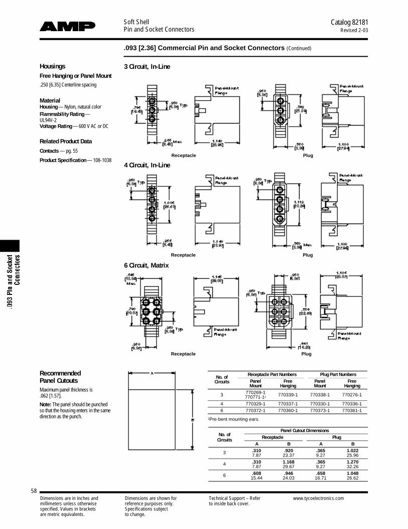
Soft ShellPin and Socket Connectors
Catalog 82181Revised 2-03
58
.093 [2.36] Commercial Pin and Socket Connectors (Continued)
Dimensions are in inches and Dimensions are shown for Technical Support – Refer www.tycoelectronics.commillimeters unless otherwise reference purposes only. to inside back cover.specified. Values in brackets Specifications subjectare metric equivalents. to change.
HousingsFree Hanging or Panel Mount.250 [6.35] Centerline spacing
MaterialHousing — Nylon, natural colorFlammability Rating —UL94V-2Voltage Rating — 600 V AC or DC
Related Product Data
Contacts — pg. 55
Product Specification — 108-1038Receptacle Plug
Receptacle Plug
Receptacle Plug
Recommended Panel CutoutsMaximum panel thickness is .062 [1.57].
Note: The panel should be punched so that the housing enters in the samedirection as the punch.
4 Circuit, In-Line
3 Circuit, In-Line
6 Circuit, Matrix
Receptacle Part Numbers Plug Part NumbersNo. ofPanel Free Panel FreeCircuitsMount Hanging Mount Hanging
3 770269-1 770339-1 770338-1 770276-1770771-11
4 770329-1 770337-1 770330-1 770336-16 770372-1 770360-1 770373-1 770361-1
1Pre-bent mounting ears.
Panel Cutout DimensionsNo. of Receptacle PlugCircuits
A B A B.310 .920 .365 1.0223 7.87 23.37 9.27 25.96.310 1.168 .365 1.2704 7.87 29.67 9.27 32.26.608 .946 .658 1.0486 15.44 24.03 16.71 26.62

Soft ShellPin and Socket Connectors
Catalog 82181Revised 2-03
59
.093 [2.36] Commercial Pin and Socket Connectors (Continued)
Dimensions are in inches and Dimensions are shown for Technical Support – Refer www.tycoelectronics.commillimeters unless otherwise reference purposes only. to inside back cover.specified. Values in brackets Specifications subjectare metric equivalents. to change.
HousingsFree Hanging or Panel Mount.250 [6.35] Centerline spacing
MaterialHousing — Nylon, natural colorFlammability Rating —UL94V-2Voltage Rating — 600 V AC or DC
Related Product DataContacts — pg. 55
Product Specification — 108-1038
Receptacle Plug
Receptacle Part Numbers Plug Part NumbersNo. of
Panel Free Panel FreeCircuitsMount Hanging Mount Hanging
2 — 770364-11 — 770365-11
3 770453-12 770451-1 770452-12 770450-11.248 [6.30] centerline.2See panel cutout dimensions on page 58.
Dual Wire
2 Circuit, In-Line
Positive Lock
2, 3 and 4 Circuit, In-Line
No. of Receptacle Part Numbers Plug Part NumbersCircuits Free Hanging Free Hanging
2 770424-11 770425-11
3 770785-1 770783-14 770784-1 770810-1
1.248 [6.30] centerline.
Receptacle Plug
Receptacle Plug
3 Circuit, In-Line
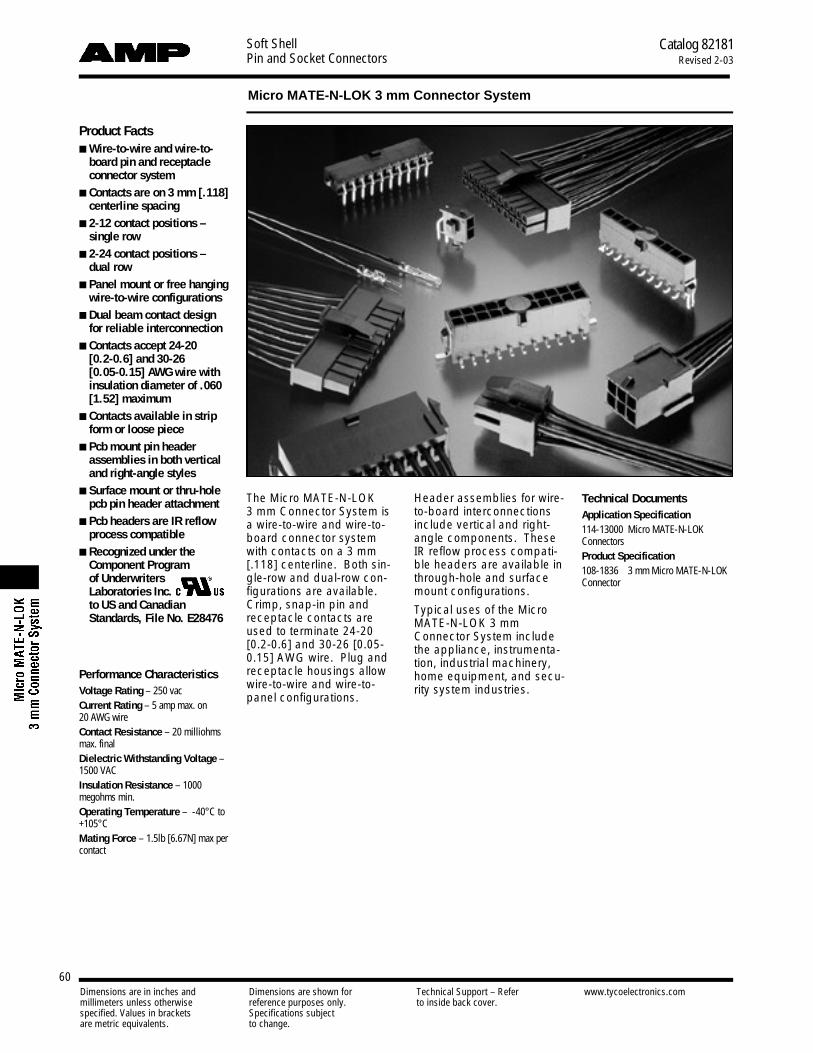
60Dimensions are in inches and Dimensions are shown for Technical Support – Refer www.tycoelectronics.commillimeters unless otherwise reference purposes only. to inside back cover.specified. Values in brackets Specifications subjectare metric equivalents. to change.
Soft ShellPin and Socket Connectors
Catalog 82181Revised 2-03
Micro MATE-N-LOK 3 mm Connector System
Product Facts■ Wire-to-wire and wire-to-
board pin and receptacleconnector system
■ Contacts are on 3 mm [.118]centerline spacing
■ 2-12 contact positions –single row
■ 2-24 contact positions – dual row
■ Panel mount or free hangingwire-to-wire configurations
■ Dual beam contact designfor reliable interconnection
■ Contacts accept 24-20 [0.2-0.6] and 30-26 [0.05-0.15] AWG wire withinsulation diameter of .060[1.52] maximum
■ Contacts available in stripform or loose piece
■ Pcb mount pin headerassemblies in both verticaland right-angle styles
■ Surface mount or thru-holepcb pin header attachment
■ Pcb headers are IR reflowprocess compatible
■ Recognized under theComponent Program of Underwriters Laboratories Inc.to US and CanadianStandards, File No. E28476
The Micro MATE-N-LOK 3 mm Connector System isa wire-to-wire and wire-to-board connector systemwith contacts on a 3 mm[.118] centerline. Both sin-gle-row and dual-row con-figurations are available.Crimp, snap-in pin andreceptacle contacts areused to terminate 24-20[0.2-0.6] and 30-26 [0.05-0.15] AWG wire. Plug andreceptacle housings allowwire-to-wire and wire-to-panel configurations.
Header assemblies for wire-to-board interconnectionsinclude vertical and right-angle components. TheseIR reflow process compati-ble headers are available inthrough-hole and surfacemount configurations.
Typical uses of the MicroMATE-N-LOK 3 mmConnector System includethe appliance, instrumenta-tion, industrial machinery,home equipment, and secu-rity system industries.
Technical DocumentsApplication Specification 114-13000 Micro MATE-N-LOKConnectorsProduct Specification 108-1836 3 mm Micro MATE-N-LOKConnector
Performance CharacteristicsVoltage Rating – 250 vacCurrent Rating – 5 amp max. on 20 AWG wireContact Resistance – 20 milliohmsmax. finalDielectric Withstanding Voltage –1500 VACInsulation Resistance – 1000megohms min.Operating Temperature – -40°C to+105°CMating Force – 1.5lb [6.67N] max percontact

Soft ShellPin and Socket Connectors
Catalog 82181Revised 2-03
Micro MATE-N-LOK 3 mm Connector System (Continued)
Dimensions are in inches and Dimensions are shown for Technical Support – Refer www.tycoelectronics.commillimeters unless otherwise reference purposes only. to inside back cover.specified. Values in brackets Specifications subjectare metric equivalents. to change.
61
To determine acceptable current carrying capacity for connector size and wire gage indicated, use the MultiplicationFactor from the chart above and multiply it times the Base rated Current at the maximum ambient operating tempera-ture shown in the current rating figure.
Multiplication FactorNumber of Wire Size (AWG)
Circuit Positions28 20
2 to 6 0.40 18 to 20 0.40 0.85
22 to 24 0.36 0.85
Connector Application . . . . . . . . . . . . . . . . . . . . . . . . . . . . . . . . . . . . . . . . . . . . . . . . 62-64Crimp, Snap-In Contacts . . . . . . . . . . . . . . . . . . . . . . . . . . . . . . . . . . . . . . . . . . . . . . . . . . 65
Receptacle HousingsSingle Row . . . . . . . . . . . . . . . . . . . . . . . . . . . . . . . . . . . . . . . . . . . . . . . . . . . . . . . . . . . . . 66Dual Row . . . . . . . . . . . . . . . . . . . . . . . . . . . . . . . . . . . . . . . . . . . . . . . . . . . . . . . . . . . . . . 67
Plug HousingsSingle Row, Free Hanging . . . . . . . . . . . . . . . . . . . . . . . . . . . . . . . . . . . . . . . . . . . . . . . . . 68Single Row, Panel Mount . . . . . . . . . . . . . . . . . . . . . . . . . . . . . . . . . . . . . . . . . . . . . . . . . . 69Dual Row, Free Hanging . . . . . . . . . . . . . . . . . . . . . . . . . . . . . . . . . . . . . . . . . . . . . . . . . . 70Dual Row, Panel Mount . . . . . . . . . . . . . . . . . . . . . . . . . . . . . . . . . . . . . . . . . . . . . . . . . . . 71
Vertical Header AssembliesSingle Row, Thru-Hole, with Retention Feature
on Soldertail and Polarization Feature to PCB. . . . . . . . . . . . . . . . . . . . . . . . . . . . . . . . . 72Single Row, Thru-Hole, with Metal Thru-Hole Hold-down . . . . . . . . . . . . . . . . . . . . . . . . . 73Single Row, Surface Mount, with Metal Thru-Hole Hold-down. . . . . . . . . . . . . . . . . . . . . . 74Single Row, Surface Mount, with Surface Mount Hold-down . . . . . . . . . . . . . . . . . . . . . . . 75Dual Row, Thru-Hole, with Retention Feature on Soldertail . . . . . . . . . . . . . . . . . . . . . . . . 76Dual Row, Thru-Hole, with Retention Feature
on Soldertail and Metal Thru-Hole Hold-down . . . . . . . . . . . . . . . . . . . . . . . . . . . . . . . . 77Dual Row, Surface Mount, with Metal Thru-Hole Hold-down . . . . . . . . . . . . . . . . . . . . . . . 78Dual Row, Surface Mount, with Surface Mount Hold-down . . . . . . . . . . . . . . . . . . . . . . . . 79
Right-Angle Header AssembliesSingle Row, Thru-Hole, with Metal Thru-Hole Hold-down . . . . . . . . . . . . . . . . . . . . . . . . . 80Single Row, Thru-Hole, with Plastic Boardlock. . . . . . . . . . . . . . . . . . . . . . . . . . . . . . . . . . 81Single Row, Surface Mount, with Metal Thru-Hole Hold-down. . . . . . . . . . . . . . . . . . . . . . 82Single Row, Surface Mount, with Surface Mount Hold-down . . . . . . . . . . . . . . . . . . . . . . . 83Single Row, Surface Mount, with Plastic Boardlock . . . . . . . . . . . . . . . . . . . . . . . . . . . . . . 84Dual Row, Thru-Hole, with Metal Thru-Hole Hold-down . . . . . . . . . . . . . . . . . . . . . . . . . . . 85Dual Row, Thru-Hole, with Plastic Boardlock . . . . . . . . . . . . . . . . . . . . . . . . . . . . . . . . . . . 86Dual Row, Surface Mount, with Metal Thru-Hole Hold-down . . . . . . . . . . . . . . . . . . . . . . . 87Dual Row, Surface Mount, with Plastic Boardlock . . . . . . . . . . . . . . . . . . . . . . . . . . . . . . . 88Dual Row, Surface Mount, with Surface Mount Hold-down . . . . . . . . . . . . . . . . . . . . . . . . 89
Current Rating Verification for 30˚C Maximum Temperature Rise 100% Energized

Soft ShellPin and Socket Connectors
Catalog 82181Revised 2-03
Micro MATE-N-LOK 3 mm Connector System (Continued)
Dimensions are in inches and Dimensions are shown for Technical Support – Refer www.tycoelectronics.commillimeters unless otherwise reference purposes only. to inside back cover.specified. Values in brackets Specifications subjectare metric equivalents. to change.
62
Connector Application —Wire-to-Wire and Wire-to-PanelSingle Row
Receptacle
Contact Housing
Plug
Contact Housing
794606-■, 794607-■,794610-■, 794611-■
Page 65
1445022-■Page 66
794608-■, 794609-■,794612-■, 794613-■
Page 65
Free Hanging1445049-■
Page 68
Panel Mount1445048-■
Page 69
Dual RowReceptacle
Contact Housing
Plug
Contact Housing
794606-■, 794607-■,794610-■, 794611-■
Page 65
794617-■Page 67
794608-■, 794609-■,794612-■, 794613-■
Page 65
Free Hanging794616-■Page 70
Panel Mount794615-■Page 71

Soft ShellPin and Socket Connectors
Catalog 82181Revised 2-03
Micro MATE-N-LOK 3 mm Connector System (Continued)
Dimensions are in inches and Dimensions are shown for Technical Support – Refer www.tycoelectronics.commillimeters unless otherwise reference purposes only. to inside back cover.specified. Values in brackets Specifications subjectare metric equivalents. to change.
63
Connector Application —Wire-to-PCBSingle Row
Receptacle
Contact Housing
Header
794606-■, 794607-■,794610-■, 794611-■
Page 65
1445022-■Page 66
Vertical Thru-Hole, with Retention Feature onSoldertail and Polarization Feature to PCB1 4 4 5 0 5 0 -■, 1445084-■, 1445093-■ (Page 72)
Vertical Thru-Hole, with Metal Thru-Hole Hold-down1 4 4 5 0 5 1 -■, 1445085-■, 1445094-■ (Page 73)
Vertical Surface Mount, with Metal Thru-Hole Hold-down1 4 4 5 0 5 2 -■, 1445086-■, 1445095-■ (Page 74)
Vertical Surface Mount, with Surface Mount Hold-down1 4 4 5 0 5 3 -■, 1445087-■, 1445096-■ (Page 75)
Right-angle, Thru-Hole, with Metal Thru-Hole Hold-down1 4 4 5 0 5 4 -■, 1445088-■, 1445097-■ (Page 80)
Right-angle, Thru-Hole, with Plastic Boardlock1 4 4 5 0 5 5 -■, 1445089-■, 1445098-■ (Page 81)
Right-angle, Surface Mount, with Metal Thru-Hole H o l d - d o w n1 4 4 5 0 5 6 -■, 1445090-■, 1445099-■ (Page 82)
Right-angle, Surface Mount, with Surface Mount H o l d - d o w n1 4 4 5 0 5 7 -■, 1445091-■, 1445100-■ (Page 83)
Right-angle, Surface Mount, and Plastic Boardlock1 4 4 5 0 5 8 -■, 1445092-■, 1445101-■ (Page 84)
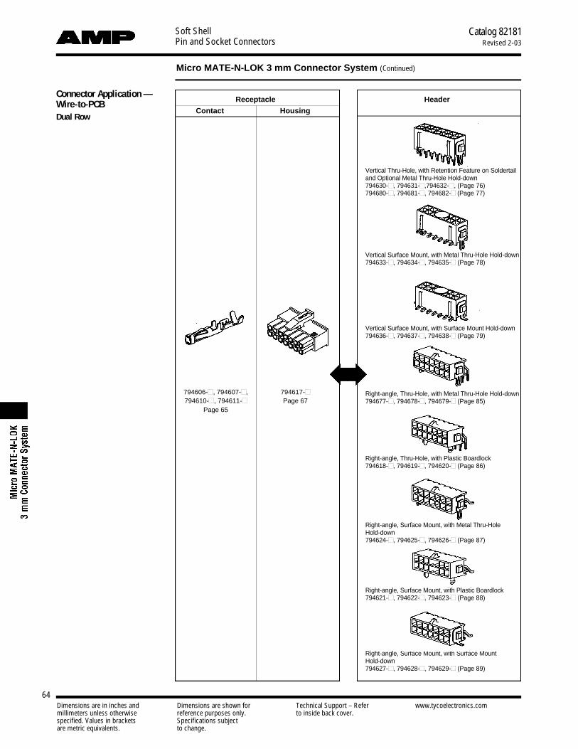
Soft ShellPin and Socket Connectors
Catalog 82181Revised 2-03
Micro MATE-N-LOK 3 mm Connector System (Continued)
Dimensions are in inches and Dimensions are shown for Technical Support – Refer www.tycoelectronics.commillimeters unless otherwise reference purposes only. to inside back cover.specified. Values in brackets Specifications subjectare metric equivalents. to change.
64
Connector Application —Wire-to-PCBDual Row
Receptacle
Contact Housing
Header
794606-■, 794607-■,794610-■, 794611-■
Page 65
794617-■Page 67
Vertical Thru-Hole, with Retention Feature on Soldertailand Optional Metal Thru-Hole Hold-down7 9 4 6 3 0 -■, 794631-■, 7 9 4 6 3 2 -■, (Page 76) 7 9 4 6 8 0 -■, 794681-■, 794682-■ (Page 77)
Vertical Surface Mount, with Metal Thru-Hole Hold-down7 9 4 6 3 3 -■, 794634-■, 794635-■ (Page 78)
Vertical Surface Mount, with Surface Mount Hold-down7 9 4 6 3 6 -■, 794637-■, 794638-■ (Page 79)
Right-angle, Thru-Hole, with Metal Thru-Hole Hold-down7 9 4 6 7 7 -■, 794678-■, 794679-■ (Page 85)
Right-angle, Thru-Hole, with Plastic Boardlock7 9 4 6 1 8 -■, 794619-■, 794620-■ (Page 86)
Right-angle, Surface Mount, with Metal Thru-Hole H o l d - d o w n7 9 4 6 2 4 -■, 794625-■, 794626-■ (Page 87)
Right-angle, Surface Mount, with Plastic Boardlock7 9 4 6 2 1 -■, 794622-■, 794623-■ (Page 88)
Right-angle, Surface Mount, with Surface Mount H o l d - d o w n7 9 4 6 2 7 -■, 794628-■, 794629-■ (Page 89)

Soft ShellPin and Socket Connectors
Catalog 82181Revised 2-03
Micro MATE-N-LOK 3 mm Connector System (Continued)
Dimensions are in inches and Dimensions are shown for Technical Support – Refer www.tycoelectronics.commillimeters unless otherwise reference purposes only. to inside back cover.specified. Values in brackets Specifications subjectare metric equivalents. to change.
65
Crimp, Snap-In Contacts
Material and FinishReceptacle — Phosphor BronzePlug — BrassPlating A — .00006 - .00016 [0.0015-0.0040] tin-leadPlating B — .000015 [0.00038] goldin mating area, tin-lead on terminationend, with entire contact nickelunderplatedPlating C — .000030 [0.00076] goldin mating area, tin-lead on terminationend, with entire contact nickelunderplated
Related Product DataConnectors used with: Receptacle Contacts used withReceptacle Housings — pages 66, 67Plug Contacts used with PlugHousings — pages 68-71
Application Tooling—pages 127-130 and 132
Contact Extraction ToolPart Number 843996-6
Receptacle ContactsWire Size Contact Part Numbers Tooling Part Numbers
Range Ins. Dia. Finish Strip LooseAWG [mm2] Range Form Piece Applicator Hand Tool
20-24 .035 - .060Plating A 794606-1 794610-1
0.50 - 0.20 0.89-1.52 Plating B 794606-2 794610-2 680893-■* 91501-1Plating C 794606-3 794610-3
26-30 .035 - .060Plating A 794607-1 794611-1
0.12 - 0.05 0.89-1.52 Plating B 794607-2 794611-2 680894-■* 91502-1Plating C 794607-3 794611-3
*1=AMPOMATOR CLS Machine, 2=AMP-O-LECTRIC Model K Terminator, 3=AMP-O-LECTRIC Model G Terminator
Plug ContactsWire Size Contact Part Numbers Tooling Part Numbers
Range Ins. Dia. Finish Strip LooseAWG [mm2] Range Form Piece Applicator Hand Tool
20-24 .035 - .060Plating A 794608-1 794612-1
0.50 - 0.20 0.89-1.52 Plating B 794608-2 794612-2 1385194-■* 91501-1Plating C 794608-3 794612-3
26-30 .035 - .060Plating A 794609-1 794613-1
0.12 -0.05 0.89-1.52 Plating B 794609-2 794613-2 1385377-■* 91502-1Plating C 794609-3 794613-3
*1=AMPOMATOR CLS Machine, 2=AMP-O-LECTRIC Model K Terminator, 3=AMP-O-LECTRIC Model G Terminator
.489[12.17] Ref.
.541[13.73] Ref.

Soft ShellPin and Socket Connectors
Catalog 82181Revised 2-03
Micro MATE-N-LOK 3 mm Connector System (Continued)
Dimensions are in inches and Dimensions are shown for Technical Support – Refer www.tycoelectronics.commillimeters unless otherwise reference purposes only. to inside back cover.specified. Values in brackets Specifications subjectare metric equivalents. to change.
66
Receptacle HousingsSingle Row
MaterialNylon, BlackFlammability Rating—UL 94V-0
Related Product DataContacts: Receptacle Contacts—page 65
Mateable Housings andHeaders: Single Row Plug Housings—pages 68,6 9Single Row Vertical Pin HeaderAssemblies—pages 72-75Single Row Right-Angle Pin HeaderAssemblies—pages 80-84
Number Dimension Part of Circuits A Numbers
2 .276 1445022-27.00
3 .394 1445022-310.00
4 .512 1445022-413.00
5 .630 1445022-516.00
6 .748 1445022-619.00
7 .866 1445022-722.00
8 .984 1445022-825.00
9 1.102 1445022-928.00
10 1.220 1-1445022-031.00
11 1.339 1-1445022-134.00
12 1.457 1-1445022-237.00
.118[3.00] Typ.
.152[3.86]
.342[8.70]
.251[6.37]
.553[14.04]
A

Soft ShellPin and Socket Connectors
Catalog 82181Revised 2-03
Micro MATE-N-LOK 3 mm Connector System (Continued)
Dimensions are in inches and Dimensions are shown for Technical Support – Refer www.tycoelectronics.commillimeters unless otherwise reference purposes only. to inside back cover.specified. Values in brackets Specifications subjectare metric equivalents. to change.
67
Receptacle Housings(Continued)
Dual Row
MaterialNylon, BlackFlammability Rating—UL 94V-0
Related Product DataContacts: Receptacle Contacts—page 65
Mateable Housings andHeaders: Dual Row Plug Housings—pages 70, 71Dual Row Vertical Pin HeaderAssemblies—pages 76-79Dual Row Right-Angle Pin HeaderAssemblies—pages 85-89
Number Dimension Part of Circuits A Numbers
2 .157 794617-24.00
4 .276 794617-47.00
6 .394 794617-610.00
8 .512 794617-813.00
10 .630 1-794617-016.00
12 .748 1-794617-219.00
14 .866 1-794617-422.00
16 .984 1-794617-625.00
18 1.102 1-794617-828.00
20 1.220 2-794617-031.00
22 1.339 2-794617-234.00
24 1.457 2-794617-437.00
.118[3.00] Typ.
.270[6.86]
.118[3.00]
A
.461[11.70]
.251[6.37]
.553[14.04]

Soft ShellPin and Socket Connectors
Catalog 82181Revised 2-03
Micro MATE-N-LOK 3 mm Connector System (Continued)
Dimensions are in inches and Dimensions are shown for Technical Support – Refer www.tycoelectronics.commillimeters unless otherwise reference purposes only. to inside back cover.specified. Values in brackets Specifications subjectare metric equivalents. to change.
68
Plug HousingsSingle Row, Free Hanging
MaterialNylon, BlackFlammability Rating—UL 94V-0
Related Product DataContacts: Plug Contacts—page 65
Mateable Housings: Single Row Receptacle Housings—page 66
Number Dimension Part of Circuits A Numbers
2 .270 1445049-26.85
3 .388 1445049-39.85
4 .506 1445049-412.85
5 .624 1445049-515.85
6 .742 1445049-618.85
7 .860 1445049-721.85
8 .978 1445049-824.85
9 1.096 1445049-927.85
10 1.215 1-1445049-030.85
11 1.333 1-1445049-133.85
12 1.451 1-1445049-236.85
.118[3.00]Typ.
.665[16.89]
.152[3.86]
.335[8.50]A
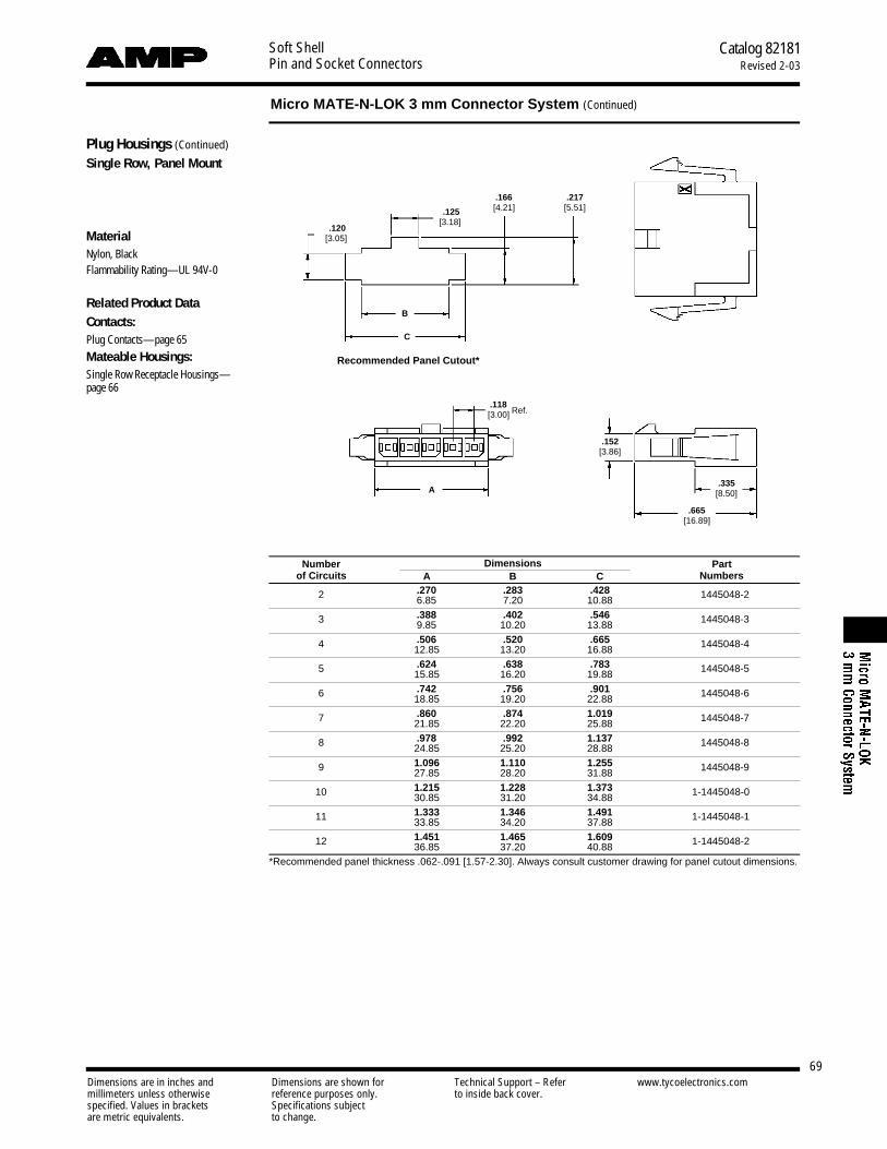
Soft ShellPin and Socket Connectors
Catalog 82181Revised 2-03
Micro MATE-N-LOK 3 mm Connector System (Continued)
Dimensions are in inches and Dimensions are shown for Technical Support – Refer www.tycoelectronics.commillimeters unless otherwise reference purposes only. to inside back cover.specified. Values in brackets Specifications subjectare metric equivalents. to change.
69
Plug Housings (Continued)
Single Row, Panel Mount
MaterialNylon, BlackFlammability Rating—UL 94V-0
Related Product DataContacts: Plug Contacts—page 65
Mateable Housings: Single Row Receptacle Housings—page 66
Number Dimensions Part of Circuits A B C Numbers
2 .270 .283 .428 1445048-26.85 7.20 10.88
3 .388 .402 .546 1445048-39.85 10.20 13.88
4 .506 .520 .665 1445048-412.85 13.20 16.88
5 .624 .638 .783 1445048-515.85 16.20 19.88
6 .742 .756 .901 1445048-618.85 19.20 22.88
7 .860 .874 1.019 1445048-721.85 22.20 25.88
8 .978 .992 1.137 1445048-824.85 25.20 28.88
9 1.096 1.110 1.255 1445048-927.85 28.20 31.88
10 1.215 1.228 1.373 1-1445048-030.85 31.20 34.88
11 1.333 1.346 1.491 1-1445048-133.85 34.20 37.88
12 1.451 1.465 1.609 1-1445048-236.85 37.20 40.88*Recommended panel thickness .062-.091 [1.57-2.30]. Always consult customer drawing for panel cutout dimensions.
.118[3.00] Ref.
C
B
. 1 2 0[3.05]
. 1 2 5[3.18]
. 1 6 6[4.21]
. 2 1 7[5.51]
. 6 6 5[16.89]
. 3 3 5[8.50]
. 1 5 2[3.86]
Recommended Panel Cutout*
A

Soft ShellPin and Socket Connectors
Catalog 82181Revised 2-03
Micro MATE-N-LOK 3 mm Connector System (Continued)
Dimensions are in inches and Dimensions are shown for Technical Support – Refer www.tycoelectronics.commillimeters unless otherwise reference purposes only. to inside back cover.specified. Values in brackets Specifications subjectare metric equivalents. to change.
70
Plug Housings (Continued)
Dual Row, Free Hanging
MaterialNylon, BlackFlammability Rating—UL 94V-0
Related Product DataContacts: Plug Contacts—page 65
Mateable Housings: Dual Row Receptacle Housings—page 67
Number Dimension Part of Circuits A Numbers
2 .157 794616-23.85
4 .276 794616-46.85
6 .394 794616-69.85
8 .512 794616-812.85
10 .630 1-794616-015.85
12 .748 1-794616-218.85
14 .866 1-794616-421.85
16 .984 1-794616-624.85
18 1.102 1-794616-827.85
20 1.220 2-794616-030.85
22 1.339 2-794616-233.85
24 1.457 2-794616-436.85
.118[3.00] Ref.
.665[16.89]
.270[6.86]
.118[3.00]
.335[8.50]A
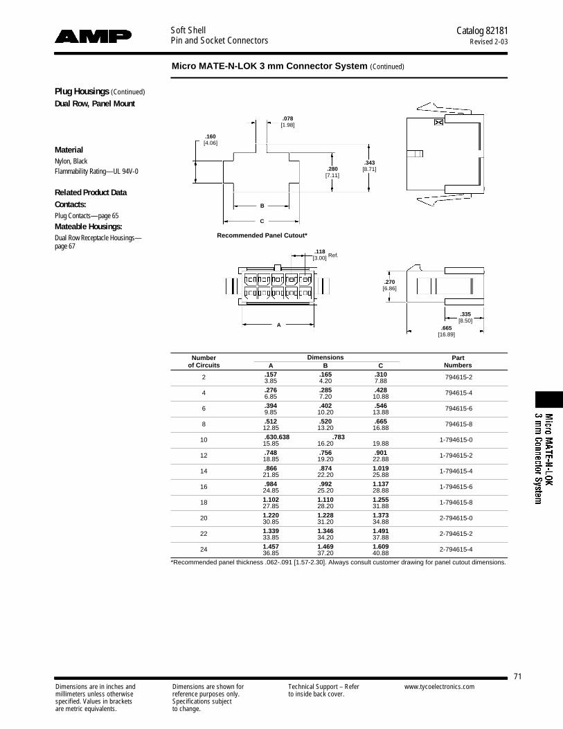
Soft ShellPin and Socket Connectors
Catalog 82181Revised 2-03
Micro MATE-N-LOK 3 mm Connector System (Continued)
Dimensions are in inches and Dimensions are shown for Technical Support – Refer www.tycoelectronics.commillimeters unless otherwise reference purposes only. to inside back cover.specified. Values in brackets Specifications subjectare metric equivalents. to change.
71
Plug Housings (Continued)
Dual Row, Panel Mount
MaterialNylon, BlackFlammability Rating—UL 94V-0
Related Product DataContacts: Plug Contacts—page 65
Mateable Housings: Dual Row Receptacle Housings—page 67
Number Dimensions Part of Circuits A B C Numbers
2 .157 .165 .310 794615-23.85 4.20 7.88
4 .276 .285 .428 794615-46.85 7.20 10.88
6 .394 .402 .546 794615-69.85 10.20 13.88
8 .512 .520 .665 794615-812.85 13.20 16.88
10 .630 .638 .783 1-794615-015.85 16.20 19.88
12 .748 .756 .901 1-794615-218.85 19.20 22.88
14 .866 .874 1.019 1-794615-421.85 22.20 25.88
16 .984 .992 1.137 1-794615-624.85 25.20 28.88
18 1.102 1.110 1.255 1-794615-827.85 28.20 31.88
20 1.220 1.228 1.373 2-794615-030.85 31.20 34.88
22 1.339 1.346 1.491 2-794615-233.85 34.20 37.88
24 1.457 1.469 1.609 2-794615-436.85 37.20 40.88*Recommended panel thickness .062-.091 [1.57-2.30]. Always consult customer drawing for panel cutout dimensions.
.118[3.00] Ref.
B
C
. 1 6 0[4.06]
. 0 7 8[1.98]
. 2 8 0[7.11]
. 3 4 3[8.71]
. 2 7 0[6.86]
. 6 6 5[16.89]
. 3 3 5[8.50]
Recommended Panel Cutout*
A

Soft ShellPin and Socket Connectors
Catalog 82181Revised 2-03
Micro MATE-N-LOK 3 mm Connector System (Continued)
Dimensions are in inches and Dimensions are shown for Technical Support – Refer www.tycoelectronics.commillimeters unless otherwise reference purposes only. to inside back cover.specified. Values in brackets Specifications subjectare metric equivalents. to change.
72
Vertical Header AssembliesSingle Row, Thru-Hole, with Retention Feature on Soldertail and Polarization Feature to PCB
Material and FinishHousing — High Temperature Nylon,BlackFlammability Rating — UL 94V-0
Contacts — BrassPlating A - .000100 [0.00254] min. tin-lead over .000050 [0.00127] min. nickelPlating B – .000015 [0.00038] gold inmating area, .000100 [0.00254] min.tin-lead in solder area, with entirecontact underplated .000050 [0.00127]min. nickelPlating C – .000030 [0.00076] gold inmating area, .000100 [0.00254] min.tin-lead in solder area, with entirecontact underplated .000050 [0.00127]min. nickel
Related Product DataMateable Housings: Single Row Receptacle Housings—page 66
Number of Dimensions Header Part Numbers Mates with
Circuits A B CReceptacle Housing
Plating A Plating B Plating C Part Number
2 .276 .360 .118 1445050-2 1445084-2 1445093-2 1445022-27.00 9.14 3.00
3 .394 .478 .236 1445050-3 1445084-3 1445093-3 1445022-310.00 12.14 6.00
4 .512 .596 .354 1445050-4 1445084-4 1445093-4 1445022-413.00 15.14 9.00
5 .630 .714 .472 1445050-5 1445084-5 1445093-5 1445022-516.00 18.14 12.00
6 .748 .832 .591 1445050-6 1445084-6 1445093-6 1445022-619.00 21.14 15.00
7 .866 .950 .709 1445050-7 1445084-7 1445093-7 1445022-722.00 24.14 18.00
8 .984 1.069 .827 1445050-8 1445084-8 1445093-8 1445022-825.00 27.14 21.00
9 1.102 1.187 .945 1445050-9 1445084-9 1445093-9 1445022-928.00 30.14 24.00
10 1.220 1.304 1.063 1-1445050-0 1-1445084-0 1-1445093-0 1-1445022-031.00 33.14 27.00
11 1.339 1.423 1.181 1-1445050-1 1-1445084-1 1-1445093-1 1-1445022-134.00 36.14 30.00
12 1.457 1.541 1.299 1-1445050-2 1-1445084-2 1-1445093-2 1-1445022-237.00 39.14 33.00*Recommended PC Board thickness .062 [1.57]. Always consult customer drawing for PC Board layout dimensions.
.118[3.00] Typ.
.118[3.00] Typ.
.118[3.00]
.031[0.80] Dia. Ref.
.040[1.02] Dia. Typ.
.050[1.27] Dia. 2 Plc.
.364[9.24] Ref.
.125[3.18] Ref.
B
C
. 0 5 1[1.30]
. 1 5 2[3.86]
. 0 7 7[1.96]
. 0 2 0[0.51]
Circuit 1
Circuit 1
Recommended PC Board Layout*
A
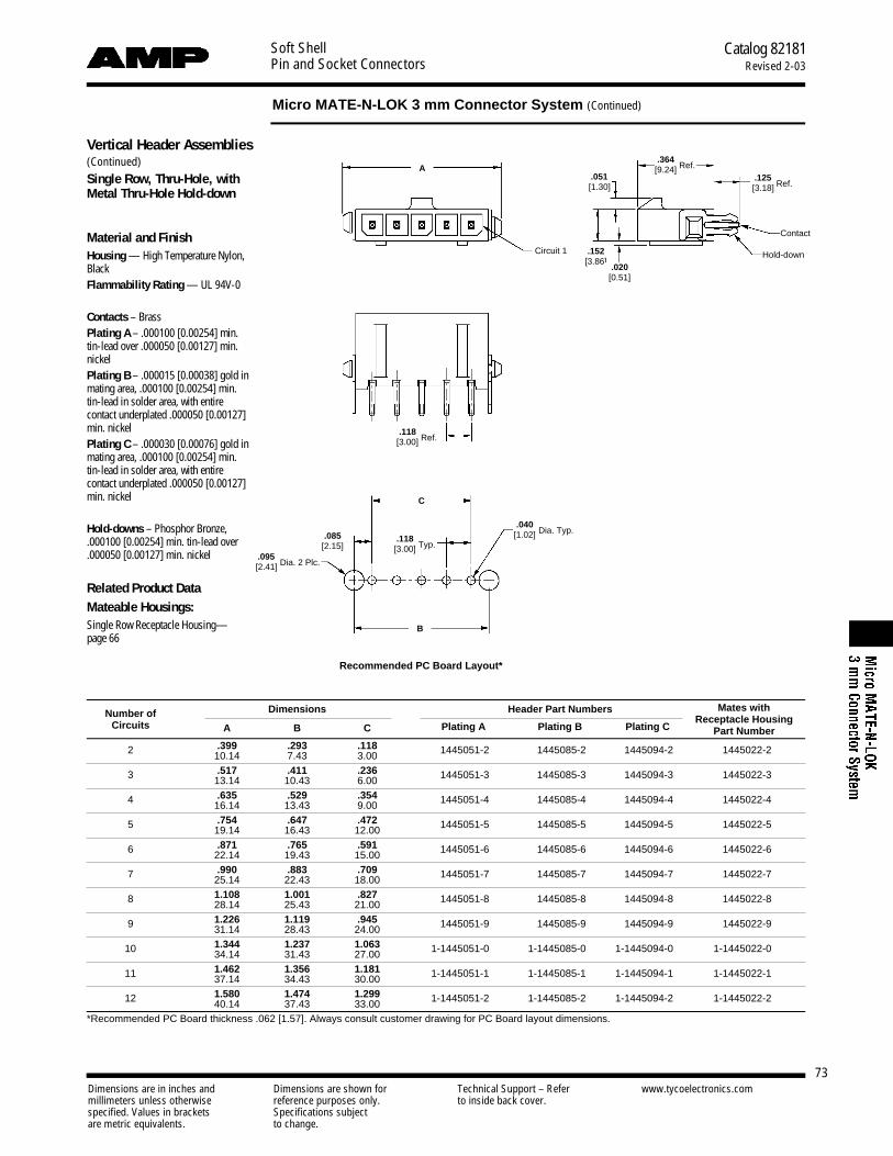
Soft ShellPin and Socket Connectors
Catalog 82181Revised 2-03
Micro MATE-N-LOK 3 mm Connector System (Continued)
Dimensions are in inches and Dimensions are shown for Technical Support – Refer www.tycoelectronics.commillimeters unless otherwise reference purposes only. to inside back cover.specified. Values in brackets Specifications subjectare metric equivalents. to change.
73
Vertical Header Assemblies(Continued)Single Row, Thru-Hole, withMetal Thru-Hole Hold-down
Material and FinishHousing — High Temperature Nylon,BlackFlammability Rating — UL 94V-0
Contacts – BrassPlating A – .000100 [0.00254] min.tin-lead over .000050 [0.00127] min.nickelPlating B – .000015 [0.00038] gold inmating area, .000100 [0.00254] min.tin-lead in solder area, with entirecontact underplated .000050 [0.00127]min. nickelPlating C – .000030 [0.00076] gold inmating area, .000100 [0.00254] min.tin-lead in solder area, with entirecontact underplated .000050 [0.00127]min. nickel
Hold-downs – Phosphor Bronze,.000100 [0.00254] min. tin-lead over.000050 [0.00127] min. nickel
Related Product DataMateable Housings: Single Row Receptacle Housing—page 66
Number of Dimensions Header Part Numbers Mates with
Circuits A B CReceptacle Housing
Plating A Plating B Plating C Part Number
2 .399 .293 .118 1445051-2 1445085-2 1445094-2 1445022-210.14 7.43 3.00
3 .517 .411 .236 1445051-3 1445085-3 1445094-3 1445022-313.14 10.43 6.00
4 .635 .529 .354 1445051-4 1445085-4 1445094-4 1445022-416.14 13.43 9.00
5 .754 .647 .472 1445051-5 1445085-5 1445094-5 1445022-519.14 16.43 12.00
6 .871 .765 .591 1445051-6 1445085-6 1445094-6 1445022-622.14 19.43 15.00
7 .990 .883 .709 1445051-7 1445085-7 1445094-7 1445022-725.14 22.43 18.00
8 1.108 1.001 .827 1445051-8 1445085-8 1445094-8 1445022-828.14 25.43 21.00
9 1.226 1.119 .945 1445051-9 1445085-9 1445094-9 1445022-931.14 28.43 24.00
10 1.344 1.237 1.063 1-1445051-0 1-1445085-0 1-1445094-0 1-1445022-034.14 31.43 27.00
11 1.462 1.356 1.181 1-1445051-1 1-1445085-1 1-1445094-1 1-1445022-137.14 34.43 30.00
12 1.580 1.474 1.299 1-1445051-2 1-1445085-2 1-1445094-2 1-1445022-240.14 37.43 33.00*Recommended PC Board thickness .062 [1.57]. Always consult customer drawing for PC Board layout dimensions.
.118[3.00] Ref.
.118[3.00] Typ.
.040[1.02] Dia. Typ.
.095[2.41] Dia. 2 Plc.
.364[9.24] Ref.
.125[3.18] Ref.
B
C
. 0 5 1[1.30]
. 1 5 2[3.86]
. 0 8 5[2.15]
. 0 2 0[0.51]
Hold-downCircuit 1
Contact
Recommended PC Board Layout*
A
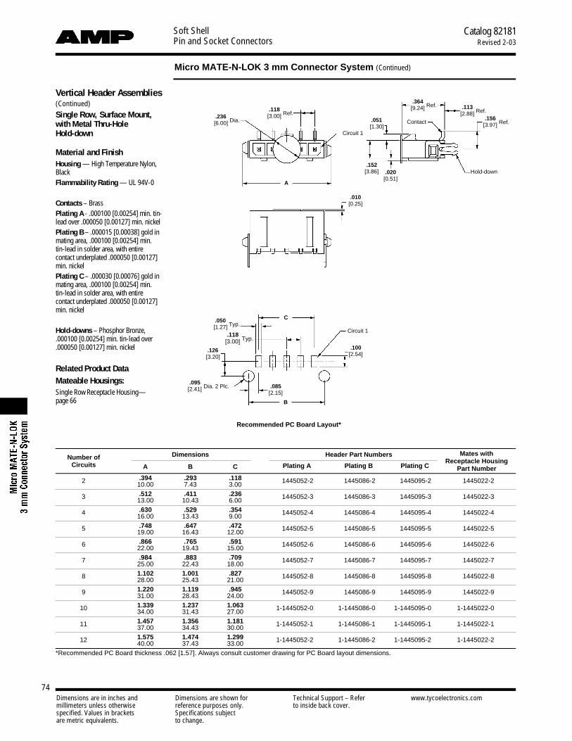
Soft ShellPin and Socket Connectors
Catalog 82181Revised 2-03
Micro MATE-N-LOK 3 mm Connector System (Continued)
Dimensions are in inches and Dimensions are shown for Technical Support – Refer www.tycoelectronics.commillimeters unless otherwise reference purposes only. to inside back cover.specified. Values in brackets Specifications subjectare metric equivalents. to change.
74
Vertical Header Assemblies(Continued)Single Row, Surface Mount, with Metal Thru-Hole Hold-down
Material and FinishHousing — High Temperature Nylon,BlackFlammability Rating — UL 94V-0
Contacts – BrassPlating A - .000100 [0.00254] min. tin-lead over .000050 [0.00127] min. nickelPlating B – .000015 [0.00038] gold inmating area, .000100 [0.00254] min.tin-lead in solder area, with entirecontact underplated .000050 [0.00127]min. nickelPlating C – .000030 [0.00076] gold inmating area, .000100 [0.00254] min.tin-lead in solder area, with entirecontact underplated .000050 [0.00127]min. nickel
Hold-downs – Phosphor Bronze,.000100 [0.00254] min. tin-lead over.000050 [0.00127] min. nickel
Related Product DataMateable Housings: Single Row Receptacle Housing—page 66
Number of Dimensions Header Part Numbers Mates with
Circuits A B CReceptacle Housing
Plating A Plating B Plating C Part Number
2 .394 .293 .118 1445052-2 1445086-2 1445095-2 1445022-210.00 7.43 3.00
3 .512 .411 .236 1445052-3 1445086-3 1445095-3 1445022-313.00 10.43 6.00
4 .630 .529 .354 1445052-4 1445086-4 1445095-4 1445022-416.00 13.43 9.00
5 .748 .647 .472 1445052-5 1445086-5 1445095-5 1445022-519.00 16.43 12.00
6 .866 .765 .591 1445052-6 1445086-6 1445095-6 1445022-622.00 19.43 15.00
7 .984 .883 .709 1445052-7 1445086-7 1445095-7 1445022-725.00 22.43 18.00
8 1.102 1.001 .827 1445052-8 1445086-8 1445095-8 1445022-828.00 25.43 21.00
9 1.220 1.119 .945 1445052-9 1445086-9 1445095-9 1445022-931.00 28.43 24.00
10 1.339 1.237 1.063 1-1445052-0 1-1445086-0 1-1445095-0 1-1445022-034.00 31.43 27.00
11 1.457 1.356 1.181 1-1445052-1 1-1445086-1 1-1445095-1 1-1445022-137.00 34.43 30.00
12 1.575 1.474 1.299 1-1445052-2 1-1445086-2 1-1445095-2 1-1445022-240.00 37.43 33.00*Recommended PC Board thickness .062 [1.57]. Always consult customer drawing for PC Board layout dimensions.
.118[3.00] Ref.
.118[3.00] Typ.
.010[0.25]
.095[2.41] Dia. 2 Plc.
.236[6.00] Dia.
.364[9.24] Ref.
.050[1.27] Typ.
.100[2.54]
.113[2.88] Ref.
B
C
A
. 0 5 1[1.30]
. 1 5 2[3.86]
. 1 2 6[3.20]
. 0 8 5[2.15]
. 0 2 0[0.51]
Contact
Circuit 1
Circuit 1
Hold-down
.156[3.97] Ref.
Recommended PC Board Layout*
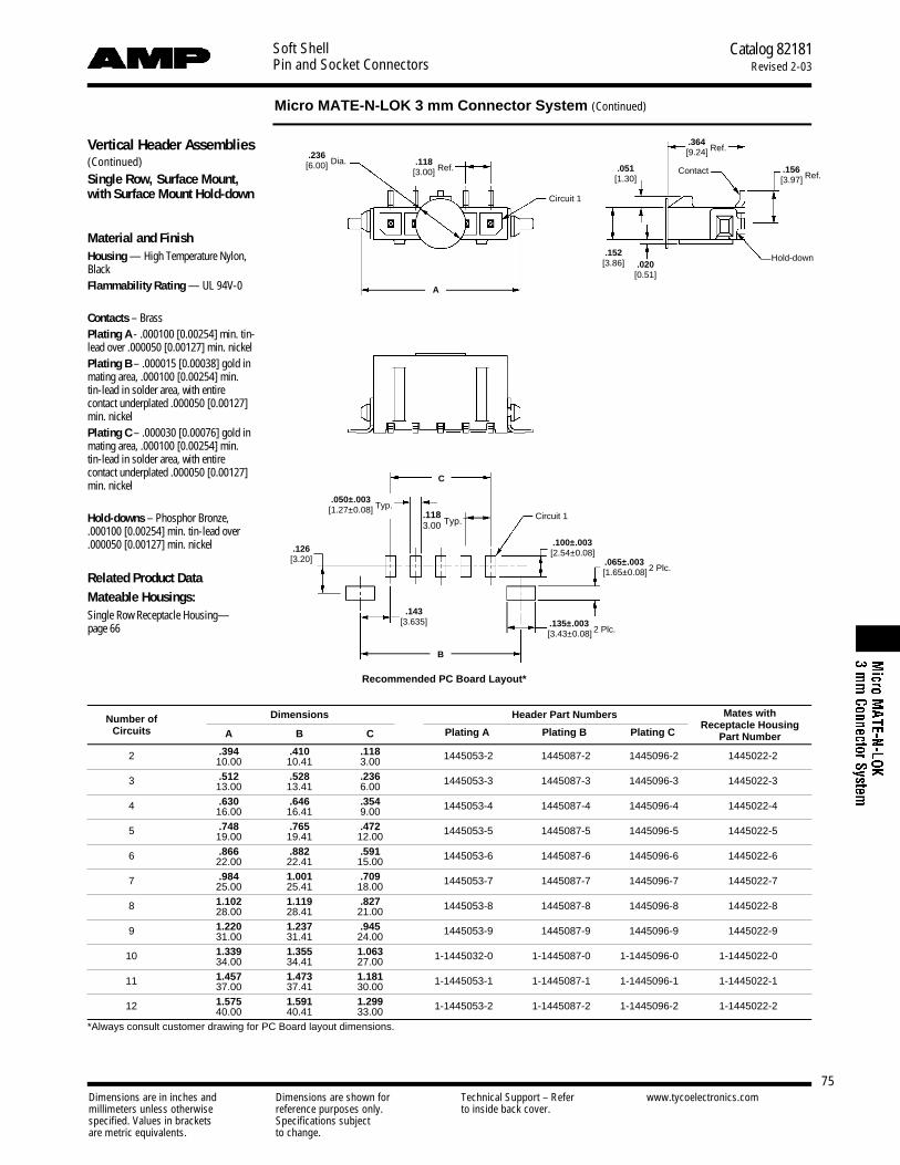
Soft ShellPin and Socket Connectors
Catalog 82181Revised 2-03
Micro MATE-N-LOK 3 mm Connector System (Continued)
Dimensions are in inches and Dimensions are shown for Technical Support – Refer www.tycoelectronics.commillimeters unless otherwise reference purposes only. to inside back cover.specified. Values in brackets Specifications subjectare metric equivalents. to change.
75
Vertical Header Assemblies(Continued)Single Row, Surface Mount,with Surface Mount Hold-down
Material and FinishHousing — High Temperature Nylon,BlackFlammability Rating — UL 94V-0
Contacts – BrassPlating A - .000100 [0.00254] min. tin-lead over .000050 [0.00127] min. nickelPlating B – .000015 [0.00038] gold inmating area, .000100 [0.00254] min.tin-lead in solder area, with entirecontact underplated .000050 [0.00127]min. nickelPlating C – .000030 [0.00076] gold inmating area, .000100 [0.00254] min.tin-lead in solder area, with entirecontact underplated .000050 [0.00127]min. nickel
Hold-downs – Phosphor Bronze,.000100 [0.00254] min. tin-lead over.000050 [0.00127] min. nickel
Related Product DataMateable Housings: Single Row Receptacle Housing—page 66
Number of Dimensions Header Part Numbers Mates with
Circuits A B CReceptacle Housing
Plating A Plating B Plating C Part Number
2 .394 .410 .118 1445053-2 1445087-2 1445096-2 1445022-210.00 10.41 3.00
3 .512 .528 .236 1445053-3 1445087-3 1445096-3 1445022-313.00 13.41 6.00
4 .630 .646 .354 1445053-4 1445087-4 1445096-4 1445022-416.00 16.41 9.00
5 .748 .765 .472 1445053-5 1445087-5 1445096-5 1445022-519.00 19.41 12.00
6 .866 .882 .591 1445053-6 1445087-6 1445096-6 1445022-622.00 22.41 15.00
7 .984 1.001 .709 1445053-7 1445087-7 1445096-7 1445022-725.00 25.41 18.00
8 1.102 1.119 .827 1445053-8 1445087-8 1445096-8 1445022-828.00 28.41 21.00
9 1.220 1.237 .945 1445053-9 1445087-9 1445096-9 1445022-931.00 31.41 24.00
10 1.339 1.355 1.063 1-1445032-0 1-1445087-0 1-1445096-0 1-1445022-034.00 34.41 27.00
11 1.457 1.473 1.181 1-1445053-1 1-1445087-1 1-1445096-1 1-1445022-137.00 37.41 30.00
12 1.575 1.591 1.299 1-1445053-2 1-1445087-2 1-1445096-2 1-1445022-240.00 40.41 33.00*Always consult customer drawing for PC Board layout dimensions.
.118[3.00] Ref.
.1183.00 Typ.
.135±.003[3.43±0.08] 2 Plc.
.065±.003[1.65±0.08] 2 Plc.
.236[6.00] Dia.
.364[9.24] Ref.
.050±.003[1.27±0.08] Typ.
.100±.003[2.54±0.08]
C
B
A
. 0 5 1[1.30]
. 1 5 2[3.86]
. 1 2 6[3.20]
. 1 4 3[3.635]
. 0 2 0[0.51]
Contact
Circuit 1
Circuit 1
Hold-down
.156[3.97] Ref.
Recommended PC Board Layout*

Soft ShellPin and Socket Connectors
Catalog 82181Revised 2-03
Micro MATE-N-LOK 3 mm Connector System (Continued)
Dimensions are in inches and Dimensions are shown for Technical Support – Refer www.tycoelectronics.commillimeters unless otherwise reference purposes only. to inside back cover.specified. Values in brackets Specifications subjectare metric equivalents. to change.
76
Vertical Header Assemblies(Continued)Dual Row, Thru-Hole, with Retention Feature on Soldertail
Material and FinishHousing — High Temperature Nylon,BlackFlammability Rating — UL 94V-0
Contacts – BrassPlating A – .000100 [0.00254] min.tin-lead over .000050 [0.00127] min.nickelPlating B – .000015 [0.00038] gold inmating area, .000100 [0.00254] min.tin-lead in solder area, with entirecontact underplated .000050 [0.00127]min. nickelPlating C – .000030 [0.00076] gold inmating area, .000100 [0.00254] min.tin-lead in solder area, with entirecontact underplated .000050 [0.00127]min. nickel
Hold-downs – Phosphor Bronze,.000100 [0.00254] min. tin-lead over.000050 [0.00127] min. nickel
Related Product DataMateable Housings: Dual Row Receptacle Housing—page 67
Number of Dimensions Header Part Numbers Mates with
Circuits A BReceptacle Housing
Plating A Plating B Plating C Part Number
2 .276 — 794630-2 794631-2 794632-2 794617-27.00
4 .394 .118 794630-4 794631-4 794632-4 794617-410.00 3.00
6 .512 .236 794630-6 794631-6 794632-6 794617-613.00 6.00
8 .630 .354 794630-8 794631-8 794632-8 794617-816.00 9.00
10 .748 .472 1-794630-0 1-794631-0 1-794632-0 1-794617-019.00 12.00
12 .866 .591 1-794630-2 1-794631-2 1-794632-2 1-794617-222.00 15.00
14 .984 .709 1-794630-4 1-794631-4 1-794632-4 1-794617-425.00 18.00
16 1.102 .827 1-794630-6 1-794631-6 1-794632-6 1-794617-628.00 21.00
18 1.220 .945 1-794630-8 1-794631-8 1-794632-8 1-794617-831.00 24.00
20 1.339 1.063 2-794630-0 2-794631-0 2-794632-0 2-794617-034.00 27.00
22 1.457 1.181 2-794630-2 2-794631-2 2-794632-2 2-794617-237.00 30.00
24 1.575 1.299 2-794630-4 2-794631-4 2-794632-4 2-794617-440.00 33.00*Recommended PC Board thickness .062 [1.57]. Always consult customer drawing for PC Board layout dimensions.
.118[3.00]
.118[3.00]
.118[3.00] Typ.
.118[3.00]
.138[3.50] Min.
.079[2.00] Min..040
[1.02] Dia. Typ.
.364[9.24]
.125[3.18]
B
A
Retention Feature LocatedOn End Contacts Only4 Plc. Ref.
. 2 7 0[6.86]
. 3 4 1[8.67]
Recommended PC Board Layout*
Section Z-Z
Z
Z

Soft ShellPin and Socket Connectors
Catalog 82181Revised 2-03
Micro MATE-N-LOK 3 mm Connector System (Continued)
Dimensions are in inches and Dimensions are shown for Technical Support – Refer www.tycoelectronics.commillimeters unless otherwise reference purposes only. to inside back cover.specified. Values in brackets Specifications subjectare metric equivalents. to change.
77
Vertical Header Assemblies(Continued)Dual Row, Thru-Hole, with Retention Feature on Soldertail and Metal Thru-Hole Hold-down
Material and FinishHousing—High Temperature Nylon,BlackFlammability Rating—UL 94V-0
Contacts – BrassPlating A – .000100 [0.00254] min.tin-lead over .000050 [0.00127] min.nickelPlating B – .000015 [0.00038] gold inmating area, .000100 [0.00254] min.tin-lead in solder area, with entirecontact underplated .000050 [0.00127]min. nickelPlating C – .000030 [0.00076] gold inmating area, .000100 [0.00254] min.tin-lead in solder area, with entirecontact underplated .000050 [0.00127]min. nickel
Hold-downs—Phosphor Bronze,.000100 [0.00254] min. tin-lead over.000050 [0.00127] min. nickel
Related Product DataMateable Housings: Dual Row Receptacle Housing—page 67
Number of Dimensions Header Part Numbers Mates with
Circuits A B CReceptacle Housing
Plating A Plating B Plating C Part Number
2 .276 — .169 794680-2 794681-2 794682-2 794617-27.00 4.30
4 .394 .118 .287 794680-4 794681-4 794682-4 794617-410.00 3.00 7.30
6 .512 .236 .406 794680-6 794681-6 794682-6 794617-613.00 6.00 10.30
8 .630 .354 .524 794680-8 794681-8 794682-8 794617-816.00 9.00 13.30
10 .748 .472 .642 1-794680-0 1-794681-0 1-794682-0 1-794617-019.00 12.00 16.30
12 .866 .591 .760 1-794680-2 1-794681-2 1-794682-2 1-794617-222.00 15.00 19.30
14 .984 .709 .878 1-794680-4 1-794681-4 1-794682-4 1-794617-425.00 18.00 22.30
16 1.102 .827 .996 1-794680-6 1-794681-6 1-794682-6 1-794617-628.00 21.00 25.30
18 1.220 .945 1.114 1-794680-8 1-794681-8 1-794682-8 1-794617-831.00 24.00 28.30
20 1.339 1.063 1.232 2-794680-0 2-794681-0 2-794682-0 2-794617-034.00 27.00 31.30
22 1.457 1.181 1.350 2-794680-2 2-794681-2 2-794682-2 2-794617-237.00 30.00 34.30
24 1.575 1.299 1.469 2-794680-4 2-794681-4 2-794682-4 2-794617-440.00 33.00 37.30*Recommended PC Board thickness .062 [1.57]. Always consult customer drawing for PC Board layout dimensions.
.118[3.00]
.118[3.00]
.084[2.13]
.118[3.00]
.118[3.00]
.059[1.50]
.079[2.00] Min..087
[2.20] Min.
.095[2.41] Dia. Typ.
.040[1.02] Dia. Typ.
.364[9.24]
.125[3.18]
B
C
A
Contact
Retention Feature LocatedOn End Contacts Only4 Plc. Ref.
. 2 7 0[6.86]
. 3 4 1[8.67]
Hold-down
Section Z-Z
Recommended PC Board Layout*
Z
Z

Soft ShellPin and Socket Connectors
Catalog 82181Revised 2-03
Micro MATE-N-LOK 3 mm Connector System (Continued)
Dimensions are in inches and Dimensions are shown for Technical Support – Refer www.tycoelectronics.commillimeters unless otherwise reference purposes only. to inside back cover.specified. Values in brackets Specifications subjectare metric equivalents. to change.
78
Vertical Header Assemblies(Continued)Dual Row, Surface Mount, with Metal Thru-Hole Hold-down
Material and FinishHousing—High Temperature Nylon,BlackFlammability Rating—UL 94V-0
Contacts – BrassPlating A – .000100 [0.00254] min.tin-lead over .000050 [0.00127] min.nickelPlating B – .000015 [0.00038] gold inmating area, .000100 [0.00254] min.tin-lead in solder area, with entirecontact underplated .000050 [0.00127]min. nickelPlating C – .000030 [0.00076] gold inmating area, .000100 [0.00254] min.tin-lead in solder area, with entirecontact underplated .000050 [0.00127]min. nickel
Hold-downs – Phosphor Bronze,.000100 [0.00254] min. tin-lead over.000050 [0.00127] min. nickel
Pick-up Button—Kapton
Related Product DataMateable Housings: Dual Row Receptacle Housing—page 67
Number of Dimensions Header Part Numbers Mates with
Circuits A B CReceptacle Housing
Plating A Plating B Plating C Part Number
2 .276 — .169 794633-2 794634-2 794635-2 794617-27.00 4.30
4 .394 .118 .287 794633-4 794634-4 794635-4 794617-410.00 3.00 7.30
6 .512 .236 .406 794633-6 794634-6 794635-6 794617-613.00 6.00 10.30
8 .630 .354 .524 794633-8 794634-8 794635-8 794617-816.00 9.00 13.30
10 .748 .472 .642 1-794633-0 1-794634-0 1-794635-0 1-794617-019.00 12.00 16.30
12 .866 .591 .760 1-794633-2 1-794634-2 1-794635-2 1-794617-222.00 15.00 19.30
14 .984 .709 .878 1-794633-4 1-794634-4 1-794635-4 1-794617-425.00 18.00 22.30
16 1.10 2.827 .996 1-794633-6 1-794634-6 1-794635-6 1-794617-628.00 21.00 25.30
18 1.220 0.945 1.114 1-794633-8 1-794634-8 1-794635-8 1-794617-831.00 24.00 28.30
20 1.339 1.063 1.232 2-794633-0 2-794634-0 2-794635-0 2-794617-034.00 27.00 31.30
22 1.457 1.181 1.350 2-794633-2 2-794634-2 2-794635-2 2-794617-237.00 30.00 34.30
24 1.575 1.299 1.469 2-794633-4 2-794634-4 2-794635-4 2-794617-440.00 33.00 37.30*Recommended PC Board thickness .062 [1.57]. Always consult customer drawing for PC Board layout dimensions.
.118[3.00]
.010[0.25]
.084[2.14]
.370[9.40]
.185[4.70] .050
[1.27]
.025[0.635]
.118[3.00] Typ.
.087[2.20] Min.
.098[2.50] Min.
.095[2.41] Dia. 2 Plc.
.100[2.54] Typ.
.236[6.00] Dia.
.050[1.27] Typ.
.364[9.24].477
[12.12]
B
C
. 2 7 0[6.86]
Circuit 1
Contact
Hold-down
. 4 3 1[10.94]
A
Recommended PC Board Layout*

Soft ShellPin and Socket Connectors
Catalog 82181Revised 2-03
Micro MATE-N-LOK 3 mm Connector System (Continued)
Dimensions are in inches and Dimensions are shown for Technical Support – Refer www.tycoelectronics.commillimeters unless otherwise reference purposes only. to inside back cover.specified. Values in brackets Specifications subjectare metric equivalents. to change.
79
Vertical Header Assemblies(Continued)Dual Row, Surface Mount, with Surface Mount Hold-down
Material and FinishHousing — High Temperature Nylon,BlackFlammability Rating — UL 94V-0
Contacts – BrassPlating A – .000100 [0.00254] min.tin-lead over .000050 [0.00127] min.nickelPlating B – .000015 [0.00038] gold inmating area, .000100 [0.00254] min.tin-lead in solder area, with entirecontact underplated .000050 [0.00127]min. nickelPlating C – .000030 [0.00076] gold inmating area, .000100 [0.00254] min.tin-lead in solder area, with entirecontact underplated .000050 [0.00127]min. nickel
Hold-downs – Phosphor Bronze,.000100 [0.00254] min. tin-lead over.000050 [0.00127] min. nickel
Pick-up Button — Kapton
Related Product DataMateable Housings: Dual Row Receptacle Housing—page 67
Number of Dimensions Header Part Numbers Mates with
Circuits A B CReceptacle Housing
Plating A Plating B Plating C Part Number
2 .276 — .286 794636-2 794637-2 794638-2 794617-27.00 7.27
4 .394 .118 .404 794636-4 794637-4 794638-4 794617-410.00 3.00 10.27
6 .512 .236 .522 794636-6 794637-6 794638-6 794617-613.00 6.00 13.27
8 .630 .354 .640 794636-8 794637-8 794638-8 794617-816.00 9.00 16.27
10 .748 .472 .758 1-794636-0 1-794637-0 1-794638-0 1-794617-019.00 12.00 19.27
12 .866 .591 .876 1-794636-2 1-794637-2 1-794638-2 1-794617-222.00 15.00 22.27
14 .984 .709 .994 1-794636-4 1-794637-4 1-794638-4 1-794617-425.00 18.00 25.27
16 1.102 .827 1.112 1-794636-6 1-794637-6 1-794638-6 1-794617-628.00 21.00 28.27
18 1.220 .945 1.230 1-794636-8 1-794637-8 1-794638-8 1-794617-831.00 24.00 31.27
20 1.339 1.063 1.349 2-794636-0 2-794637-0 2-794638-0 2-794617-034.00 27.00 34.27
22 1.457 1.181 1.467 2-794636-2 2-794637-2 2-794638-2 2-794617-237.00 30.00 37.27
24 1.575 1.299 1.585 2-794636-4 2-794637-4 2-794638-4 2-794617-440.00 33.00 40.27*Always consult customer drawing for PC Board layout dimensions.
.135[3.43] Typ.
.065[1.65] Typ.
. 1 1 8[3.00] Min.
.364[9.24]
.010[0.25]
.050[1.27] Typ.
.100[2.54]
B
C
A
. 1 1 8[3.00]
. 1 1 8[3.00] Typ.
. 2 3 6[6.00] Dia.
. 2 7 0[6.86]
. 3 7 0[9.40] . 1 8 5
[4.70]
. 0 2 5[.635]
. 4 3 1[10.94]
Contact
Circuit 1
Hold-down
.098[2.50] Min.
.032[0.825]
.068[1.715]
.050[1.27]
Recommended PC Board Layout*

Soft ShellPin and Socket Connectors
Catalog 82181Revised 2-03
Micro MATE-N-LOK 3 mm Connector System (Continued)
Dimensions are in inches and Dimensions are shown for Technical Support – Refer www.tycoelectronics.commillimeters unless otherwise reference purposes only. to inside back cover.specified. Values in brackets Specifications subjectare metric equivalents. to change.
80
Right-Angle HeaderAssembliesSingle Row, Thru-Hole, with Metal Thru-Hole Hold-down
Material and FinishHousing—High Temperature Nylon,BlackFlammability Rating—UL 94V-0
Contacts – BrassPlating A - .000100 [0.00254] min.tin-lead over .000050 [0.00127] min.nickelPlating B – .000015 [0.00038] gold inmating area, .000100 [0.00254] min.tin-lead in solder area, with entirecontact underplated .000050 [0.00127]min. nickelPlating C – .000030 [0.00076] gold inmating area, .000100 [0.00254] min.tin-lead in solder area, with entirecontact underplated .000050 [0.00127]min. nickel
Hold-downs – Phosphor Bronze,.000100 [0.00254] min. tin-lead over.000050 [0.00127] min. nickel
Related Product DataMateable Housings: Single Row Receptacle Housing—page 66
Number of Dimensions Header Part Numbers Mates with
Circuits A B CReceptacle Housing
Plating A Plating B Plating C Part Number
2 .399 .293 .118 1445054-2 1445088-2 1445097-2 1445022-210.14 7.43 3.00
3 .517 .411 .236 1445054-3 1445088-3 1445097-3 1445022-313.14 10.43 6.00
4 .635 .529 .354 1445054-4 1445088-4 1445097-4 1445022-416.14 13.43 9.00
5 .754 .647 .472 1445054-5 1445088-5 1445097-5 1445022-519.14 16.43 12.00
6 .871 .765 .591 1445054-6 1445088-6 1445097-6 1445022-622.14 19.43 15.00
7 .990 .883 .709 1445054-7 1445088-7 1445097-7 1445022-725.14 22.43 18.00
8 1.108 1.001 .827 1445054-8 1445088-8 1445097-8 1445022-828.14 25.43 21.00
9 1.226 1.119 .945 1445054-9 1445088-9 1445097-9 1445022-931.14 28.43 24.00
10 1.344 1.237 1.063 1-1445054-0 1-1445088-0 1-1445097-0 1-1445022-034.14 31.43 27.00
11 1.462 1.356 1.181 1-1445054-1 1-1445088-1 1-1445097-1 1-1445022-137.14 34.43 30.00
12 1.580 1.474 1.299 1-1445054-2 1-1445088-2 1-1445097-2 1-1445022-240.14 37.43 33.00*Recommended PC Board thickness .062 [1.57]. Always consult customer drawing for PC Board layout dimensions.
. 1 1 8[3.00] Ref.
. 2 8 5[7.25] Ref.
. 1 1 8[3.00] Typ.
. 0 5 1[ 1 . 3 0 ]
. 3 5 1[8.92] Ref.
.085[2.15].170
[4.32]
B
C
A
.020[0.51]
. 1 5 2[3.86]
Contact
Circuit 1
Circuit 1
Hold-down
.095[2.41] Dia. 2 Plc.
.040[1.02] Dia. Typ.
Recommended PC Board Layout*
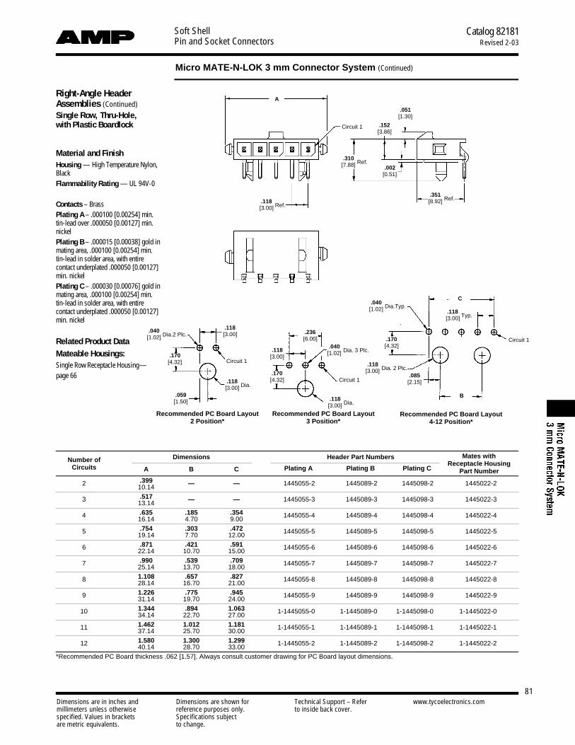
Soft ShellPin and Socket Connectors
Catalog 82181Revised 2-03
Micro MATE-N-LOK 3 mm Connector System (Continued)
Dimensions are in inches and Dimensions are shown for Technical Support – Refer www.tycoelectronics.commillimeters unless otherwise reference purposes only. to inside back cover.specified. Values in brackets Specifications subjectare metric equivalents. to change.
81
Right-Angle HeaderAssemblies (Continued)Single Row, Thru-Hole, with Plastic Boardlock
Material and FinishHousing — High Temperature Nylon,BlackFlammability Rating — UL 94V-0
Contacts – BrassPlating A – .000100 [0.00254] min.tin-lead over .000050 [0.00127] min.nickelPlating B – .000015 [0.00038] gold inmating area, .000100 [0.00254] min.tin-lead in solder area, with entirecontact underplated .000050 [0.00127]min. nickelPlating C – .000030 [0.00076] gold inmating area, .000100 [0.00254] min.tin-lead in solder area, with entirecontact underplated .000050 [0.00127]min. nickel
Related Product DataMateable Housings: Single Row Receptacle Housing—page 66
Number of Dimensions Header Part Numbers Mates with
Circuits A B CReceptacle Housing
Plating A Plating B Plating C Part Number
2 .399 — — 1445055-2 1445089-2 1445098-2 1445022-210.14
3 .517 — — 1445055-3 1445089-3 1445098-3 1445022-313.14
4 .635 .185 .354 1445055-4 1445089-4 1445098-4 1445022-416.14 4.70 9.00
5 .754 .303 .472 1445055-5 1445089-5 1445098-5 1445022-519.14 7.70 12.00
6 .871 .421 .591 1445055-6 1445089-6 1445098-6 1445022-622.14 10.70 15.00
7 .990 .539 .709 1445055-7 1445089-7 1445098-7 1445022-725.14 13.70 18.00
8 1.108 .657 .827 1445055-8 1445089-8 1445098-8 1445022-828.14 16.70 21.00
9 1.226 .775 .945 1445055-9 1445089-9 1445098-9 1445022-931.14 19.70 24.00
10 1.344 .894 1.063 1-1445055-0 1-1445089-0 1-1445098-0 1-1445022-034.14 22.70 27.00
11 1.462 1.012 1.181 1-1445055-1 1-1445089-1 1-1445098-1 1-1445022-137.14 25.70 30.00
12 1.580 1.300 1.299 1-1445055-2 1-1445089-2 1-1445098-2 1-1445022-240.14 28.70 33.00*Recommended PC Board thickness .062 [1.57]. Always consult customer drawing for PC Board layout dimensions.
A
.118[3.00] Ref.
.351[8.92] Ref.
.051[1.30]
.002[0.51]
.152[3.86]
.310[7.88] Ref.
Circuit 1
Circuit 1
C
B
.085[2.15]
.118[3.00]
.118[3.00]
.059[1.50]
.236[6.00]
.170[4.32]
.170[4.32]
.170[4.32]
.118[3.00] Typ.
.118[3.00] Dia.
.118[3.00] Dia.
.040[1.02] Dia.Typ.
.040[1.02] Dia.2 Plc.
.118[3.00] Dia. 2 Plc.
.040[1.02] Dia. 3 Plc.
Recommended PC Board Layout 4-12 Position*
Recommended PC Board Layout3 Position*
Recommended PC Board Layout 2 Position*
Circuit 1
Circuit 1

Soft ShellPin and Socket Connectors
Catalog 82181Revised 2-03
Micro MATE-N-LOK 3 mm Connector System (Continued)
Dimensions are in inches and Dimensions are shown for Technical Support – Refer www.tycoelectronics.commillimeters unless otherwise reference purposes only. to inside back cover.specified. Values in brackets Specifications subjectare metric equivalents. to change.
82
Right-Angle HeaderAssemblies (Continued)Single Row, Surface Mount, with Metal Thru-Hole Hold-down
Material and FinishHousing — High Temperature Nylon,BlackFlammability Rating — UL 94V-0
Contacts – BrassPlating A – .000100 [0.00254] min.tin-lead over .000050 [0.00127] min.nickelPlating B – .000015 [0.00038] gold inmating area, .000100 [0.00254] min.tin-lead in solder area, with entirecontact underplated .000050 [0.00127]min. nickelPlating C – .000030 [0.00076] gold inmating area, .000100 [0.00254] min.tin-lead in solder area, with entirecontact underplated .000050 [0.00127]min. nickel
Hold-downs – Phosphor Bronze,.000100 [0.00254] min. tin-lead over.000050 [0.00127] min. nickel
Related Product DataMateable Housings: Single Row Receptacle Housing—page 66
Number of Dimensions Header Part Numbers Mates with
Circuits A B CReceptacle Housing
Plating A Plating B Plating C Part Number
2 .394 .293 .118 1445056-2 1445090-2 1445099-2 1445022-210.00 7.43 3.00
3 .512 .411 .236 1445056-3 1445090-3 1445099-3 1445022-313.00 10.43 6.00
4 .630 .529 .354 1445056-4 1445090-4 1445099-4 1445022-416.00 13.43 9.00
5 .748 .647 .472 1445056-5 1445090-5 1445099-5 1445022-519.00 16.43 12.00
6 .866 .765 .591 1445056-6 1445090-6 1445099-6 1445022-622.00 19.43 15.00
7 .984 .883 .709 1445056-7 1445090-7 1445099-7 1445022-725.00 22.43 18.00
8 1.102 1.001 .827 1445056-8 1445090-8 1445099-8 1445022-828.00 25.43 21.00
9 1.220 1.119 0.945 1445056-9 1445090-9 1445099-9 1445022-931.00 28.43 24.00
10 1.339 1.237 1.063 1-1445056-0 1-1445090-0 1-1445099-0 1-1445022-034.00 31.43 27.00
11 1.457 1.356 1.181 1-1445056-1 1-1445090-1 1-1445099-1 1-1445022-137.00 34.43 30.00
12 1.575 1.474 1.299 1-1445056-2 1-1445090-2 1-1445099-2 1-1445022-240.00 37.43 33.00*Recommended PC Board thickness .062 [1.57]. Always consult customer drawing for PC Board layout dimensions.
A
.050[1.27] Typ.
.115[2.92]
.051[1.30]
.439[11.16] Ref.
.020[0.51]
.152[3.86]
.285[7.25] Ref.
.118[3.00] Ref.
.118[3.00] Typ.
Hold-down
Contact
Circuit 1
Circuit 1
B
C
.216[5.48]
.085[2.15]
.095[2.41] Dia. 2 Plc.
Recommended PC Board Layout*
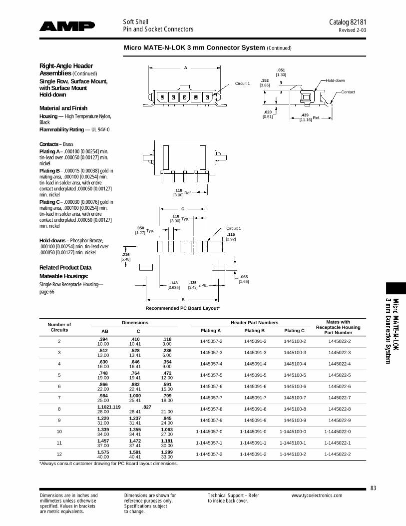
Soft ShellPin and Socket Connectors
Catalog 82181Revised 2-03
Micro MATE-N-LOK 3 mm Connector System (Continued)
Dimensions are in inches and Dimensions are shown for Technical Support – Refer www.tycoelectronics.commillimeters unless otherwise reference purposes only. to inside back cover.specified. Values in brackets Specifications subjectare metric equivalents. to change.
83
Right-Angle HeaderAssemblies (Continued)Single Row, Surface Mount, with Surface Mount Hold-down
Material and FinishHousing — High Temperature Nylon,BlackFlammability Rating — UL 94V-0
Contacts – BrassPlating A – .000100 [0.00254] min.tin-lead over .000050 [0.00127] min.nickelPlating B – .000015 [0.00038] gold inmating area, .000100 [0.00254] min.tin-lead in solder area, with entirecontact underplated .000050 [0.00127]min. nickelPlating C – .000030 [0.00076] gold inmating area, .000100 [0.00254] min.tin-lead in solder area, with entirecontact underplated .000050 [0.00127]min. nickel
Hold-downs – Phosphor Bronze,.000100 [0.00254] min. tin-lead over.000050 [0.00127] min. nickel
Related Product DataMateable Housings: Single Row Receptacle Housing—page 66
Number of Dimensions Header Part Numbers Mates with
Circuits A B CReceptacle Housing
Plating A Plating B Plating C Part Number
2 .394 .410 .118 1445057-2 1445091-2 1445100-2 1445022-210.00 10.41 3.00
3 .512 .528 .236 1445057-3 1445091-3 1445100-3 1445022-313.00 13.41 6.00
4 .630 .646 .354 1445057-4 1445091-4 1445100-4 1445022-416.00 16.41 9.00
5 .748 .764 .472 1445057-5 1445091-5 1445100-5 1445022-519.00 19.41 12.00
6 .866 .882 .591 1445057-6 1445091-6 1445100-6 1445022-622.00 22.41 15.00
7 .984 1.000 .709 1445057-7 1445091-7 1445100-7 1445022-725.00 25.41 18.00
8 1.102 1.119 .827 1445057-8 1445091-8 1445100-8 1445022-828.00 28.41 21.00
9 1.220 1.237 .945 1445057-9 1445091-9 1445100-9 1445022-931.00 31.41 24.00
10 1.339 1.355 1.063 1-1445057-0 1-1445091-0 1-1445100-0 1-1445022-034.00 34.41 27.00
11 1.457 1.472 1.181 1-1445057-1 1-1445091-1 1-1445100-1 1-1445022-137.00 37.41 30.00
12 1.575 1.591 1.299 1-1445057-2 1-1445091-2 1-1445100-2 1-1445022-240.00 40.41 33.00*Always consult customer drawing for PC Board layout dimensions.
A
.050[1.27] Typ.
.135[3.43] 2 Plc.
.051[1.30]
.439[11.16] Ref.
.020[0.51]
.152[3.86]
.118[3.00] Ref.
.118[3.00] Typ.
Hold-down
Contact
Circuit 1
Circuit 1
B
C
.216[5.48]
.143[3.635]
.115[2.92]
.065[1.65]
Recommended PC Board Layout*

Soft ShellPin and Socket Connectors
Catalog 82181Revised 2-03
Micro MATE-N-LOK 3 mm Connector System (Continued)
Dimensions are in inches and Dimensions are shown for Technical Support – Refer www.tycoelectronics.commillimeters unless otherwise reference purposes only. to inside back cover.specified. Values in brackets Specifications subjectare metric equivalents. to change.
84
Right-Angle HeaderAssemblies (Continued)Single Row, Surface Mount, with Plastic Boardlock
Material and FinishHousing — High Temperature Nylon,BlackFlammability Rating — UL 94V-0
Contacts – BrassPlating A – .000100 [0.00254] min.tin-lead over .000050 [0.00127] min.nickelPlating B – .000015 [0.00038] gold inmating area, .000100 [0.00254] min.tin-lead in solder area, with entirecontact underplated .000050 [0.00127]min. nickelPlating C – .000030 [0.00076] gold inmating area, .000100 [0.00254] min.tin-lead in solder area, with entirecontact underplated .000050 [0.00127]min. nickel
Related Product DataMateable Housings: Single Row Receptacle Housing—page 66
Number of Dimensions Header Part Numbers Mates with
Circuits A B CReceptacle Housing
Plating A Plating B Plating C Part Number
2 .394 — — 1445058-2 1445092-2 1445101-2 1445022-210.00
3 .512 — — 1445058-3 1445092-3 1445101-3 1445022-313.00
4 .630 .185 .354 1445058-4 1445092-4 1445101-4 1445022-416.00 4.70 9.00
5 .748 .303 .472 1445058-5 1445092-5 1445101-5 1445022-519.00 7.70 12.00
6 .866 .421 .591 1445058-6 1445092-6 1445101-6 1445022-622.00 10.70 15.00
7 .984 .539 .709 1445058-7 1445092-7 1445101-7 1445022-725.00 13.70 18.00
8 1.102 .657 .827 1445058-8 1445092-8 1445101-8 1445022-828.00 16.70 21.00
9 1.220 .776 .945 1445058-9 1445092-9 1445101-9 1445022-931.00 19.70 24.00
10 1.339 .894 1.063 1-1445058-0 1-1445092-0 1-1445101-0 1-1445022-034.00 22.70 27.00
11 1.457 1.012 1.181 1-1445058-1 1-1445092-1 1-1445101-1 1-1445022-137.00 25.70 30.00
12 1.575 1.130 1.299 1-1445058-2 1-1445092-2 1-1445101-2 1-1445022-240.00 28.70 33.00*Recommended PC Board thickness .062 [1.57]. Always consult customer drawing for PC Board layout dimensions.
A
.050[1.27] Typ.
.050[1.27] Typ.
.050[1.27] Typ.
.051[1.30]
.439[11.16] Ref.
.181[4.60] Ref.
.310[7.88] Ref.
.020[0.51]
.152[3.86]
.118[3.00] Ref.
.118[3.00] Typ.
.118[3.00] Dia.
.118[3.00] Dia.
.118[3.00]
.118[3.00]
.059[1.50]
.236[6.00]
.118[3.00] Dia. 2 Plc.
Circuit 1
Circuit 1
Circuit 1Circuit 1
B
C
.085[2.15]
.216[5.48]
.216[5.48]
.216[5.48] .115
[2.92]
.115[2.92]
.115[2.92]
Recommended PC Board Layout* 4-12 Positions
Recommended PC Board Layout *3 Position
Recommended PC Board Layout *2 Position
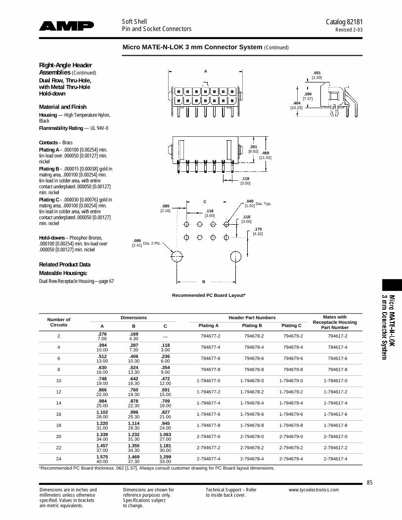
Soft ShellPin and Socket Connectors
Catalog 82181Revised 2-03
Micro MATE-N-LOK 3 mm Connector System (Continued)
Dimensions are in inches and Dimensions are shown for Technical Support – Refer www.tycoelectronics.commillimeters unless otherwise reference purposes only. to inside back cover.specified. Values in brackets Specifications subjectare metric equivalents. to change.
85
Right-Angle HeaderAssemblies (Continued)Dual Row, Thru-Hole, with Metal Thru-Hole Hold-down
Material and FinishHousing — High Temperature Nylon,BlackFlammability Rating — UL 94V-0
Contacts – BrassPlating A – .000100 [0.00254] min.tin-lead over .000050 [0.00127] min.nickelPlating B – .000015 [0.00038] gold inmating area, .000100 [0.00254] min.tin-lead in solder area, with entirecontact underplated .000050 [0.00127]min. nickelPlating C – .000030 [0.00076] gold inmating area, .000100 [0.00254] min.tin-lead in solder area, with entirecontact underplated .000050 [0.00127]min. nickel
Hold-downs – Phosphor Bronze,.000100 [0.00254] min. tin-lead over.000050 [0.00127] min. nickel
Related Product DataMateable Housings: Dual Row Receptacle Housing—page 67
Number of Dimensions Header Part Numbers Mates with
Circuits A B CReceptacle Housing
Plating A Plating B Plating C Part Number
2 .276 .169 794677-2 794678-2 794679-2 794617-27.00 4.30 —
4 .394 .287 .118 794677-4 794678-4 794679-4 794617-410.00 7.30 3.00
6 .512 .406 .236 794677-6 794678-6 794679-6 794617-613.00 10.30 6.00
8 .630 .524 .354 794677-8 794678-8 794679-8 794617-816.00 13.30 9.00
10 .748 .642 .472 1-794677-0 1-794678-0 1-794679-0 1-794617-019.00 16.30 12.00
12 .866 .760 .591 1-794677-2 1-794678-2 1-794679-2 1-794617-222.00 19.30 15.00
14 .984 .878 .709 1-794677-4 1-794678-4 1-794679-4 1-794617-425.00 22.30 18.00
16 1.102 .996 .827 1-794677-6 1-794678-6 1-794679-6 1-794617-628.00 25.30 21.00
18 1.220 1.114 .945 1-794677-8 1-794678-8 1-794679-8 1-794617-831.00 28.30 24.00
20 1.339 1.232 1.063 2-794677-0 2-794678-0 2-794679-0 2-794617-034.00 31.30 27.00
22 1.457 1.350 1.181 2-794677-2 2-794678-2 2-794679-2 2-794617-237.00 34.30 30.00
24 1.575 1.469 1.299 2-794677-4 2-794678-4 2-794679-4 2-794617-440.00 37.30 33.00*Recommended PC Board thickness .062 [1.57]. Always consult customer drawing for PC Board layout dimensions.
A .051[1.30]
.469[11.92]
.351[8.92]
.404[10.25]
.290[7.37]
.118[3.00]
.170[4.32]
.118[3.00]
.118[3.00]
.085[2.16]
B
C
Recommended PC Board Layout*
.040[1.02] Dia. Typ.
.095[2.41] Dia. 2 Plc.

Soft ShellPin and Socket Connectors
Catalog 82181Revised 2-03
Micro MATE-N-LOK 3 mm Connector System (Continued)
Dimensions are in inches and Dimensions are shown for Technical Support – Refer www.tycoelectronics.commillimeters unless otherwise reference purposes only. to inside back cover.specified. Values in brackets Specifications subjectare metric equivalents. to change.
86
Right-Angle HeaderAssemblies (Continued)Dual Row, Thru-Hole, with Plastic Boardlock
Material and FinishHousing — High Temperature Nylon,BlackFlammability Rating — UL 94V-0
Contacts – BrassPlating A - .000100 [0.00254] min. tin-lead over .000050 [0.00127] min. nickelPlating B – .000015 [0.00038] gold inmating area, .000100 [0.00254] min.tin-lead in solder area, with entirecontact underplated .000050 [0.00127]min. nickelPlating C – .000030 [0.00076] gold inmating area, .000100 [0.00254] min.tin-lead in solder area, with entirecontact underplated .000050 [0.00127]min. nickel
Related Product DataMateable Housings: Dual Row Receptacle Housing—page 67
Number of Dimensions Header Part Numbers Mates with
Circuits A B CReceptacle Housing
Plating A Plating B Plating C Part Number
2 .276 — — 794618-2 794619-2 794620-2 794617-27.00
4 .394 — .118 794618-4 794619-4 794620-4 794617-410.00 3.00
6 .512 — .236 794618-6 794619-6 794620-6 794617-613.00 6.00
8 .630 .185 .354 794618-8 794619-8 794620-8 794617-816.00 4.70 9.00
10 .748 .303 .472 1-794618-0 1-794619-0 1-794620-0 1-794617-019.00 7.70 12.00
12 .866 .421 .591 1-794618-2 1-794619-2 1-794620-2 1-794617-222.00 10.70 15.00
14 .984 .539 .709 1-794618-4 1-794619-4 1-794620-4 1-794617-425.00 13.70 18.00
16 1.102 .657 .827 1-794618-6 1-794619-6 1-794620-6 1-794617-628.00 16.70 21.00
18 1.220 .776 .945 1-794618-8 1-794619-8 1-794620-8 1-794617-831.00 19.70 24.00
20 1.339 .894 1.063 2-794618-0 2-794619-0 2-794620-0 2-794617-034.00 22.70 27.00
22 1.457 1.012 1.181 2-794618-2 2-794619-2 2-794620-2 2-794617-237.00 25.70 30.00
24 1.575 1.130 1.299 2-794618-4 2-794619-4 2-794620-4 2-794617-440.00 28.70 33.00*Recommended PC Board thickness .062 [1.57]. Always consult customer drawing for PC Board layout dimensions.
.051[1.30]
.428[10.88]
.290[7.37]
A
C
B
.469[11.92]
.351[8.92]
.118[3.00]
.040[1.02] Dia. Typ.
.118[3.00]
.170[4.32]
.085[2.16]
.181[4.60] Min.
.138[3.50] Min.
.197[5.00] Min.
.222[5.65] Min.
.181[4.60] Min.
.256[6.50] Min.
.118[3.00]
.236[6.00]
.118[3.00]
.170[4.32]
.118[3.00]
.118[3.00]
.118[3.00]
.059[1.50]
2 Position
4 Position
6 Position 8 Thru 24 Position
.118[3.00] Dia. Typ.
Recommended PC Board Layout*

Soft ShellPin and Socket Connectors
Catalog 82181Revised 2-03
Micro MATE-N-LOK 3 mm Connector System (Continued)
Dimensions are in inches and Dimensions are shown for Technical Support – Refer www.tycoelectronics.commillimeters unless otherwise reference purposes only. to inside back cover.specified. Values in brackets Specifications subjectare metric equivalents. to change.
87
Right-Angle HeaderAssemblies (Continued)Dual Row, Surface Mount, with Metal Thru-Hole Hold-down
Material and FinishHousing — High Temperature Nylon,BlackFlammability Rating — UL 94V-0
Contacts – BrassPlating A – .000100 [0.00254] min.tin-lead over .000050 [0.00127] min.nickelPlating B – .000015 [0.00038] gold inmating area, .000100 [0.00254] min.tin-lead in solder area, with entirecontact underplated .000050 [0.00127]min. nickelPlating C – .000030 [0.00076] gold inmating area, .000100 [0.00254] min.tin-lead in solder area, with entirecontact underplated .000050 [0.00127]min. nickel
Hold-downs – Phosphor Bronze,.000100 [0.00254] min. tin-lead over.000050 [0.00127] min. nickel
Related Product DataMateable Housings: Dual Row Receptacle Housing—page 67
Number of Dimensions Header Part Numbers Mates with
Circuits A B CReceptacle Housing
Plating A Plating B Plating C Part Number
2 .276 .169 — 794624-2 794625-2 794626-2 794617-27.00 4.30
4 .394 .287 .118 794624-4 794625-4 794626-4 794617-410.00 7.30 3.00
6 .512 .406 .236 794624-6 794625-6 794626-6 794617-613.00 10.30 6.00
8 .630 .524 .354 794624-8 794625-8 794626-8 794617-816.00 13.30 9.00
10 .748 .642 .472 1-794624-0 1-794625-0 1-794626-0 1-794617-019.00 16.30 12.00
12 .866 .760 .591 1-794624-2 1-794625-2 1-794626-2 1-794617-222.00 19.30 15.00
14 .984 .878 .709 1-794624-4 1-794625-4 1-794626-4 1-794617-425.00 22.30 18.00
16 1.102 .996 .827 1-794624-6 1-794625-6 1-794626-6 1-794617-628.00 25.30 21.00
18 1.220 1.114 .945 1-794624-8 1-794625-8 1-794626-8 1-794617-831.00 28.30 24.00
20 1.339 1.232 1.063 2-794624-0 2-794625-0 2-794626-0 2-794617-034.00 31.30 27.00
22 1.457 1.350 1.181 2-794624-2 2-794625-2 2-794626-2 2-794617-237.00 34.30 30.00
24 1.575 1.469 1.299 2-794624-4 2-794625-4 2-794626-4 2-794617-440.00 37.30 33.00*Recommended PC Board thickness .062 [1.57]. Always consult customer drawing for PC Board layout dimensions.
A
.050[1.27] Typ.
.087[2.20] Min.
.222[5.65] Min.
.051[1.30]
.439[11.16]
.615[15.63]
.404[10.25]
.290[7.37]
.118[3.00]
.118[3.00]
Hold-down
Contacts
Circuit 1
B
C
.216[5.48]
.398[10.10]
.085[2.15]
.115[2.92]
.025[0.635]
.057[1.46]
.095[2.41] Dia. 2 Plc.
Recommended PC Board Layout*

Soft ShellPin and Socket Connectors
Catalog 82181Revised 2-03
Micro MATE-N-LOK 3 mm Connector System (Continued)
Dimensions are in inches and Dimensions are shown for Technical Support – Refer www.tycoelectronics.commillimeters unless otherwise reference purposes only. to inside back cover.specified. Values in brackets Specifications subjectare metric equivalents. to change.
88
Right-Angle HeaderAssemblies (Continued)Dual Row, Surface Mount, with Plastic Boardlock
Material and FinishHousing — High Temperature Nylon,BlackFlammability Rating — UL 94V-0
Contacts – BrassPlating A – .000100 [0.00254] min.tin-lead over .000050 [0.00127] min.nickelPlating B – .000015 [0.00038] gold inmating area, .000100 [0.00254] min.tin-lead in solder area, with entirecontact underplated .000050 [0.00127]min. nickelPlating C – .000030 [0.00076] gold inmating area, .000100 [0.00254] min.tin-lead in solder area, with entirecontact underplated .000050 [0.00127]min. nickel
Related Product DataMateable Housings: Dual Row Receptacle Housing—page 67
Number of Dimensions Header Part Numbers Mates with
Circuits A B CReceptacle Housing
Plating A Plating B Plating C Part Number
2 .276 — — 794621-2 794622-2 794623-2 794617-27.00
4 .394 — .118 794621-4 794622-4 794623-4 794617-410.00 3.00
6 .512 — .236 794621-6 794622-6 794623-6 794617-613.00 6.00
8 .630 .185 .354 794621-8 794622-8 794623-8 794617-816.00 4.70 9.00
10 .748 .303 .472 1-794621-0 1-794622-0 1-794623-0 1-794617-019.00 7.70 12.00
12 .866 .421 .591 1-794621-2 1-794622-2 1-794623-2 1-794617-222.00 10.70 15.00
14 .984 .539 .709 1-794621-4 1-794622-4 1-794623-4 1-794617-425.00 13.70 18.00
16 1.102 .657 .827 1-794621-6 1-794622-6 1-794623-6 1-794617-628.00 16.70 21.00
18 1.220 .776 .945 1-794621-8 1-794622-8 1-794623-8 1-794617-831.00 19.70 24.00
20 1.339 .894 1.063 2-794621-0 2-794622-0 2-794623-0 2-794617-034.00 22.70 27.00
22 1.457 1.012 1.181 2-794621-2 2-794622-2 2-794623-2 2-794617-237.00 25.70 30.00
24 1.575 1.130 1.299 2-794621-4 2-794622-4 2-794623-4 2-794617-440.00 28.70 33.00*Recommended PC Board thickness .062 [1.57]. Always consult customer drawing for PC Board layout dimensions.
A
.051[1.30]
.439[11.16]
.615[15.63]
.118[3.00]
.428[10.88]
.290[7.37]
C
B
.118[3.00] Dia. Typ.
.118[3.00]
.236[6.00]
.118[3.00]
.118[3.00]
.118[3.00]
.115[2.92]
.398[10.10]
.398[10.10]
.216[5.48]
.216[5.48]
.085[2.15]
.059[1.50]
.181[4.60] Min.
. 2 2 2[5.65] M i n .
.181[4.60] Min.
. 2 5 6[6.50] M i n ..197
[5.00] Min.
.138[3.50] Min.
Recommended PC Board Layout*
2 Position
4 Position
6 Position8 Thru 24 Position
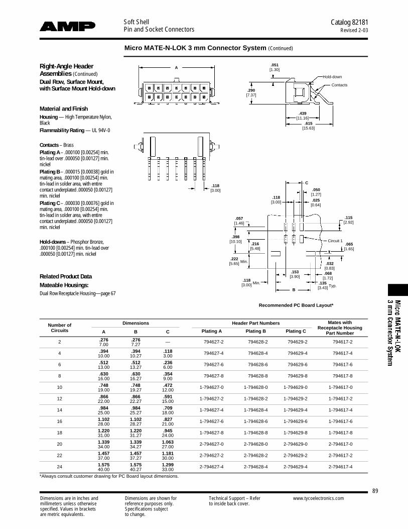
Soft ShellPin and Socket Connectors
Catalog 82181Revised 2-03
Micro MATE-N-LOK 3 mm Connector System (Continued)
Dimensions are in inches and Dimensions are shown for Technical Support – Refer www.tycoelectronics.commillimeters unless otherwise reference purposes only. to inside back cover.specified. Values in brackets Specifications subjectare metric equivalents. to change.
89
Right-Angle HeaderAssemblies (Continued)Dual Row, Surface Mount, with Surface Mount Hold-down
Material and FinishHousing — High Temperature Nylon,BlackFlammability Rating — UL 94V-0
Contacts – BrassPlating A – .000100 [0.00254] min.tin-lead over .000050 [0.00127] min.nickelPlating B – .000015 [0.00038] gold inmating area, .000100 [0.00254] min.tin-lead in solder area, with entirecontact underplated .000050 [0.00127]min. nickelPlating C – .000030 [0.00076] gold inmating area, .000100 [0.00254] min.tin-lead in solder area, with entirecontact underplated .000050 [0.00127]min. nickel
Hold-downs – Phosphor Bronze,.000100 [0.00254] min. tin-lead over.000050 [0.00127] min. nickel
Related Product DataMateable Housings: Dual Row Receptacle Housing—page 67
Number of Dimensions Header Part Numbers Mates with
Circuits A B CReceptacle Housing
Plating A Plating B Plating C Part Number
2 .276 .276 — 794627-2 794628-2 794629-2 794617-27.00 7.27
4 .394 .394 .118 794627-4 794628-4 794629-4 794617-410.00 10.27 3.00
6 .512 .512 .236 794627-6 794628-6 794629-6 794617-613.00 13.27 6.00
8 .630 .630 .354 794627-8 794628-8 794629-8 794617-816.00 16.27 9.00
10 .748 .748 .472 1-794627-0 1-794628-0 1-794629-0 1-794617-019.00 19.27 12.00
12 .866 .866 .591 1-794627-2 1-794628-2 1-794629-2 1-794617-222.00 22.27 15.00
14 .984 .984 .709 1-794627-4 1-794628-4 1-794629-4 1-794617-425.00 25.27 18.00
16 1.102 1.102 .827 1-794627-6 1-794628-6 1-794629-6 1-794617-628.00 28.27 21.00
18 1.220 1.220 .945 1-794627-8 1-794628-8 1-794629-8 1-794617-831.00 31.27 24.00
20 1.339 1.339 1.063 2-794627-0 2-794628-0 2-794629-0 2-794617-034.00 34.27 27.00
22 1.457 1.457 1.181 2-794627-2 2-794628-2 2-794629-2 2-794617-237.00 37.27 30.00
24 1.575 1.575 1.299 2-794627-4 2-794628-4 2-794629-4 2-794617-440.00 40.27 33.00*Always consult customer drawing for PC Board layout dimensions.
A.051
[1.30]
.439[11.16]
.615[15.63]
.050[1.27]
.115[2.92]
.118[3.00]
.398[10.10]
.118[3.00]
.153[3.90]
.068[1.72]
.057[1.46]
.032[0.83]
.025[0.64]
.118[3.00] Min.
.290[7.37]
Hold-down
Contacts
C
B
Circuit 1.216[5.48]
.222[5.65] Min.
.065[1.65]
.135[3.43] Typ.
Recommended PC Board Layout*

90Dimensions are in inches and Dimensions are shown for Technical Support – Refer www.tycoelectronics.commillimeters unless otherwise reference purposes only. to inside back cover.specified. Values in brackets Specifications subjectare metric equivalents. to change.
Soft ShellPin and Socket Connectors
Catalog 82181Revised 2-03
Mini-Universal MATE-N-LOK 2 Connectors
Performance CharacteristicsThe Mini-Universal MATE-N-LOK 2Connector performance characteristicsfound on pages 90 and 91 are based onfree hanging connectors, loaded withcontacts crimped on stranded wire.
Low Level Termination Resistance20 milliohms max. total resistancebetween wire crimps of a mated pin andsocket
Dielectric Withstanding Voltage1500 V AC or DC between adjacent circuits at sea level
Insulation Resistance100 megohms minimum between adjacent circuits
Voltage Rating 600 V AC or DC
Contact Retention 20 lb. min. per contact
Durability 25 cycles, mating and unmating
Current Rating up to 10.5 amps per circuit; 2 position
Mating Force 2.5 lb. max. per circuit
Unmating Force 0.25 lb. minimumper circuit
Product Facts■ One molded piece, sec-
ondary locking plug and caphousing assemblies
■ Three-point stabilization toprovide better terminal position
■ Fully polarized to provideproper plug-to-cap mating
■ Lanceless contacts for tangle-free handling
■ Toolless contact removal
■ Tin or duplex gold platedc o n t a c t s
■ Available in 2 thru 24 circuitsizes wire-to-wire and wire-t o - b o a r d
■ Mates with standard Mini-Universal MATE-N-LOK headers and connectors
■ Contacts available in stripand loose piece
■ Polarized housings availablein UL 94V-0 or UL 94V-2flammability rated material
■ Mini-Universal MATE-N-LOK 2pins and sockets can beintermixed in Mini-UniversalMATE-N-LOK 2 housings
■ Mini-Universal MATE-N-LOK 2pins and sockets can n o tb eused in standard Mini-Universal MATE-N-LOKh o u s i n g s
■ Contacts accept wire size range 30-16 AWG [.05-1.2 mm2]
■ .163 [4.14] centerline spacing
■ Not for interrupting current
■ Recognized under the C o m p o n e n tProgram ofUnderwriters LaboratoriesInc., File No. E28476
■ Recognized by VDE underRegistration Number 118488
Termination ContactResistance Crimp
Wire SizeTest Resistance
Tensile ForceAWG mm2
Current Milliohms Force (Min.)(Amps) (Max. Init.) lbs. N
30 .05 — — — —28 .08 — — — —26 .12 — — 4 1824 .2 — — — —22 .3 — — 11 4920 .5 — — 13 5818 .8 — — 15 6716 1.2 — — 18 80
Technical DocumentsProduct Specifications1 0 8 - 1 6 9 3 Mini-Universal MATE-N-LOK 2
C o n n e c t o r s1 0 8 - 1 6 9 4 Mini-Universal MATE-N-LOK 2
H e a d e r s
Application Specification1 1 4 - 1 1 1 1 Mini-Universal MATE-N-LOK 2
C o n n e c t o r s
Instruction Sheet4 0 8 -3 3 9 3 Mini-Universal MATE-N-LOK 2
C o n n e c t o r s
Mini-Universal MATE-N-LOK 2 connec-tors also will withstand the following tests:
Housing Lock Strength 6 lb. min.
Thermal Shock –55°C to +105°C
Temperature-Humidity Cycling25°C to 65°C at 95 RH
Vibration 10-55-10 cycles per minuteat .06 inch total excursion
Physical Shock 18 drops, 50 G half-sine at 11 milliseconds

Soft ShellPin and Socket Connectors
Catalog 82181Revised 2-03
91Dimensions are in inches and Dimensions are shown for Technical Support – Refer www.tycoelectronics.commillimeters unless otherwise reference purposes only. to inside back cover.specified. Values in brackets Specifications subjectare metric equivalents. to change.
Mini-Universal MATE-N-LOK 2 Connectors (Continued)
PerformanceCharacteristics (Continued)Maximum Current Maximum currentrating of Mini-Universal MATE-N-LOK 2connectors is limited by the maximumoperating temperature of the housingswhich is 105°C (gold) or 85°C (tin)including the temperature rise of thecontacts which is a maximum of 30°C.There are several variables which have adirect effect on this maximum current-carrying capability for a given connectorand must be considered for each appli-cation. These variables are:
Wire Size Larger diameter wire willcarry more current since it has lessinternal resistance to current flow andthus generates less heat. Longer wirelengths also enhance current-carryingcapabilities since the wire conducts heataway from the connector.
Connector Size In general, the morecircuits in a connector, the less currentcan be carried.
Ambient Temperature The higherthe ambient temperature, the less currentcan be carried in any given connector.
Printed Wiring Board ConductorSize The finished trace conductor widthand thickness should be maximized toallow for the greatest current-carryingcapacity and heat dissipation.
ContactsPin diameter .039 [0.99]
MaterialBrass Stock Thickness .010 [0.25]These contacts can be used in eitherMini-Universal MATE-N-LOK 2 Plug orCap housings only.
Related Product DataProduct Specifications1 0 8 - 1 6 9 3 Mini-Universal MATE-N-LOK 2
C o n n e c t o r s1 0 8 - 1 6 9 4 Mini-Universal MATE-N-LOK 2
H e a d e r s
Application Specification1 1 4 - 1 1 1 1 Mini-Universal MATE-N-LOK 2
C o n n e c t o r s
Performance Characteristics — pg. 90and 91Housings — pg. 92 and 93Technical Documents — pg. 90 and 126
Current Rating Verification for 308C Maximum Temperature Rise 100% Energized
Pin Socket
Contact Part NumbersHDM HandWire Size
Ins. Dia. FinishPin Socket Applicator ToolRange
Range Strip Loose Strip Loose Part No. Part No.AWG [mm2]Form Form Form Form
30-26 .035-.050 Pre-tin 794216-1 794224-1 794217-1 794225-1 567418-12
567418-22 90717-2[.05-.12] .889-1.27 Duplex1 794216-3 794224-3 794217-3 794225-3 567418-32
26-22 .047-.069 Pre-tin 794218-1 794226-1 794219-1 794227-1 567066-33
567066-43 91529-1[.12-.3] 1.19-1.75 Duplex1 794218-3 794226-3 794219-3 794227-3 567066-53
22-18 .059-.094 Pre-tin 794220-1 794228-1 794221-1 794229-1 680854-12
680854-22 91522-1[.3-.8] 1.50-2.39 Duplex1 794220-3 794228-3 794221-3 794229-3 680854-32
20-16 .079-.126 Pre-tin 794222-1 794230-1 794223-1 794231-1 680582-22
[.5-1.2] 2.01-3.20 Duplex1 794222-3 794230-3 794223-3 794231-3 680582-32 91594-1
1Duplex Finish—Plated with .000030 [.000762] min. gold in mating area and .000100 [.00254] min. tin-lead in crimping area over .000050 [.00127] min. nickel underplate on entire contact.
2HDM Applicator part number ending in -1 is used on AMPOMATER CLS Machine with T or G Terminators, -2 is usedon AMP-O-LECTRIC Model K Machine, -3 is used on AMP-O-ELECTRIC Model G Machine.
3HDM Applicator part number ending in -3 is used on AMPOMATOR CLS Machine with T or G Terminators, -4 is usedon AMP-O-LECTRIC Model K Machine, -5 is used on AMP-O-LECTRIC Model G Machine.
See page 132 for further information.
Not to be used with Mini-Universal MATE-N-LOK Connectors
6 Circuit Connector (Wire-to-Wire)
2 Circuit Connector (Wire-to-Wire)
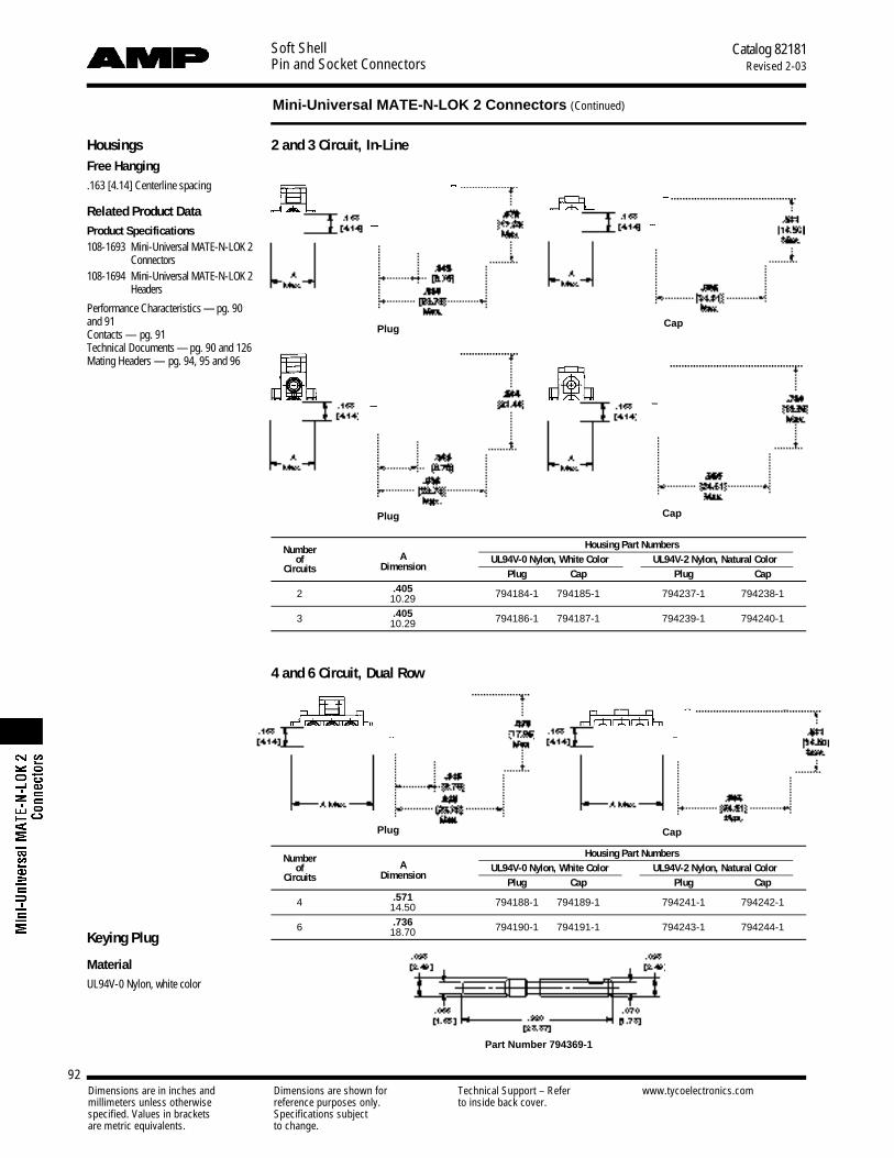
Soft ShellPin and Socket Connectors
Catalog 82181Revised 2-03
92Dimensions are in inches and Dimensions are shown for Technical Support – Refer www.tycoelectronics.commillimeters unless otherwise reference purposes only. to inside back cover.specified. Values in brackets Specifications subjectare metric equivalents. to change.
Mini-Universal MATE-N-LOK 2 Connectors (Continued)
HousingsFree Hanging.163 [4.14] Centerline spacing
Related Product DataProduct Specifications1 0 8 - 1 6 9 3 Mini-Universal MATE-N-LOK 2
C o n n e c t o r s1 0 8 - 1 6 9 4 Mini-Universal MATE-N-LOK 2
H e a d e r s
Performance Characteristics — pg. 90and 91Contacts — pg. 91Technical Documents — pg. 90 and 126Mating Headers — pg. 94, 95 and 96
2 and 3 Circuit, In-Line
4 and 6 Circuit, Dual Row
Number Housing Part Numbersof A UL94V-0 Nylon, White Color UL94V-2 Nylon, Natural Color
Circuits DimensionPlug Cap Plug Cap
2 .405 794184-1 794185-1 794237-1 794238-110.29
3 .405 794186-1 794187-1 794239-1 794240-110.29
Number Housing Part Numbersof A UL94V-0 Nylon, White Color UL94V-2 Nylon, Natural Color
Circuits DimensionPlug Cap Plug Cap
4 .571 794188-1 794189-1 794241-1 794242-114.50
6 .736 794190-1 794191-1 794243-1 794244-118.70Keying Plug
MaterialUL94V-0 Nylon, white color
Part Number 794369-1
Plug Cap
CapPlug
Plug Cap
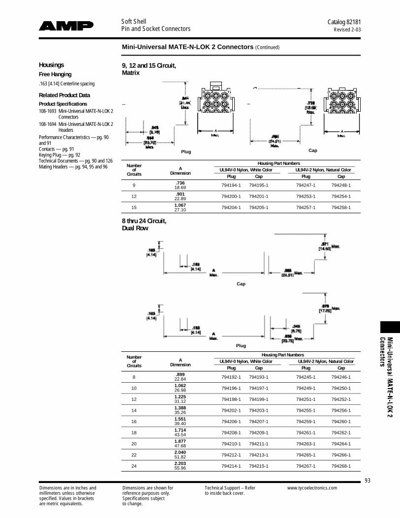
Soft ShellPin and Socket Connectors
Catalog 82181Revised 2-03
93Dimensions are in inches and Dimensions are shown for Technical Support – Refer www.tycoelectronics.commillimeters unless otherwise reference purposes only. to inside back cover.specified. Values in brackets Specifications subjectare metric equivalents. to change.
Mini-Universal MATE-N-LOK 2 Connectors (Continued)
HousingsFree Hanging
.163 [4.14] Centerline spacing
Related Product DataProduct Specifications1 0 8 - 1 6 9 3 Mini-Universal MATE-N-LOK 2
C o n n e c t o r s1 0 8 - 1 6 9 4 Mini-Universal MATE-N-LOK 2
HeadersPerformance Characteristics — pg. 90and 91Contacts — pg. 91Keying Plug — pg. 92Technical Documents — pg. 90 and 126Mating Headers — pg. 94, 95 and 96
9, 12 and 15 Circuit, Matrix
8 thru 24 Circuit, Dual Row
Number Housing Part Numbersof A UL94V-0 Nylon, White Color UL94V-2 Nylon, Natural Color
Circuits DimensionPlug Cap Plug Cap
9 .736 794194-1 794195-1 794247-1 794248-118.69
12 .901 794200-1 794201-1 794253-1 794254-122.89
15 1.067 794204-1 794205-1 794257-1 794258-127.10
Number Housing Part Numbersof A UL94V-0 Nylon, White Color UL94V-2 Nylon, Natural Color
Circuits DimensionPlug Cap Plug Cap
8 .899 794192-1 794193-1 794245-1 794246-122.84
10 1.062 794196-1 794197-1 794249-1 794250-126.98
12 1.225 794198-1 794199-1 794251-1 794252-131.12
14 1.388 794202-1 794203-1 794255-1 794256-135.26
16 1.551 794206-1 794207-1 794259-1 794260-139.40
18 1.714 794208-1 794209-1 794261-1 794262-143.54
20 1.877 794210-1 794211-1 794263-1 794264-147.68
22 2.040 794212-1 794213-1 794265-1 794266-151.82
24 2.203 794214-1 794215-1 794267-1 794268-155.96
CapPlug
Plug
Cap

Soft ShellPin and Socket Connectors
Catalog 82181Revised 2-03
94Dimensions are in inches and Dimensions are shown for Technical Support – Refer www.tycoelectronics.commillimeters unless otherwise reference purposes only. to inside back cover.specified. Values in brackets Specifications subjectare metric equivalents. to change.
Mini-Universal MATE-N-LOK 2 Connectors (Continued)
Vertical PC Board Pin Headers.163 [4.14] Centerline spacing
MaterialHousing — Nylon, white
Flammability Rating— UL94V-0Contacts — BrassSolder tail diameter .039 [1.00]
Related Product DataProduct Specifications1 0 8 - 1 6 9 3 Mini-Universal MATE-N-LOK 2
C o n n e c t o r s1 0 8 - 1 6 9 4 Mini-Universal MATE-N-LOK 2
H e a d e r sPerformance Characteristics — pg. 90and 91Recommended PC Board HoleLayout —pg. 97Technical Documents — pg. 90 and 126
Mating ConnectorsMini-Universal MATE-N-LOK 2Plug Housings— pg. 92 and 93
Mini-Universal MATE-N-LOKPlug Housings— pg. 103 and 104
2 and 3 Circuit, In-Line
9, 12 and 15 Circuit, Matrix
4, 6, 8, 10 and 12 Circuit, Dual Row.220
[5.58] .531[13.49]
.030[0.76] .387
[9.83]
.175[4.44]
.175[4.44]
.030[.762].531
[13.49]
.175[4.44]
.030[.762].531
[13.49]
A
A
A
.550[13.97]
Mates with Plug HousingNumber of Style A Pin
Vertical Pin Header Part Numbers Part NumberCircuits Dim. Finish With Without (Using Socket Contacts)
Drain Holes Drain Holes Mini-Universal Mini-Universal MATE-N-LOK MATE-N-LOK 2
2 In-Line .387 Tin-Lead1 770166-1 770872-1172165-1 794184-19.83 Duplex2 770166-2 770872-2
3 In-Line .550 Tin-Lead1 770170-1 770873-1172166-1 794186-113.97 Duplex2 770170-2 770873-2
4 Dual Row .387 Tin-Lead1 770174-1 770874-1172167-1 794188-19.83 Duplex2 770174-2 770874-2
6 Dual Row .550 Tin-Lead1 770178-1 770875-1172168-1 794190-113.97 Duplex2 770178-2 770875-2
8 Dual Row .713 Tin-Lead1 794065-1 794073-1770579-1 794192-118.11 Duplex2 794065-2 794073-2
9 Matrix .551 Tin-Lead1 770182-1 770876-1172169-1 794194-114.00 Duplex2 770182-2 770876-2
10 Dual Row .877 Tin-Lead1 770743-1 770858-1770580-1 794196-122.28 Duplex2 770743-2 770858-2
Dual Row 1.039 Tin-Lead1 794066-1 770621-1770581-1 794198-1
1226.39 Duplex2 794066-2 770621-2
Matrix .713 Tin-Lead1 770186-1 794040-1172170-1 794200-118.11 Duplex2 770186-2 794040-2
14 Dual Row 1.202 Tin-Lead1 794067-1 794074-1770582-1 794202-130.53 Duplex2 794067-2 794074-2
15 Matrix .877 Tin-Lead1 770190-1 770859-1172171-1 794204-122.28 Duplex2 770190-2 770859-2
16 Dual Row 1.365 Tin-Lead1 794068-1 794075-1770583-1 794206-134.67 Duplex2 794068-2 794075-2
18 Dual Row 1.528 Tin-Lead1 794069-1 794076-1770584-1 794208-138.81 Duplex2 794069-2 794076-2
20 Dual Row 1.691 Tin-Lead1 794070-1 794077-1770585-1 794210-142.95 Duplex2 794070-2 794077-2
22 Dual Row 1.854 Tin-Lead1 794071-1 794078-1770586-1 794212-147.09 Duplex2 794071-2 794078-2
24 Dual Row 2.017 Tin-Lead1 794072-1 794079-1770587-1 794214-151.23 Duplex2 794072-2 794079-2
1Tin-Lead Finish—Plated with .000150 [.00381] min. tin-lead over .000050 [.00127] min. nickel underplate on entirecontact.
2Duplex Finish—Plated with .000030 [.000762] min. gold in mating area and matte tin-lead on solder tail end over.000050 [.00127] min. nickel underplate on entire contact.
A
14, 16, 18, 20, 22 and 24 Circuit, Dual Row
.175[4.44]
.030[.762].531
[13.49]

Catalog 82181Revised 2-03
95Dimensions are in inches and Dimensions are shown for Technical Support – Refer www.tycoelectronics.commillimeters unless otherwise reference purposes only. to inside back cover.specified. Values in brackets Specifications subjectare metric equivalents. to change.
Soft ShellPin and Socket Connectors
Mini-Universal MATE-N-LOK 2 Connectors (Continued)
Vertical PC Board Blindmate Pin Headers.163 [4.14] Centerline spacing
MaterialHousing — Nylon, white
Flammability Rating — UL94V-0Contacts — BrassSolder tail diameter .039 [1.00]
Related Product DataProduct Specifications1 0 8 - 1 6 9 3 Mini-Universal MATE-N-LOK 2
C o n n e c t o r s1 0 8 - 1 6 9 4 Mini-Universal MATE-N-LOK 2
H e a d e r sPerformance Characteristics — pg. 90and 91Recommended PC Board HoleLayout —pg. 97Technical Documents — pg. 90 and 126
Mating ConnectorsMini-Universal MATE-N-LOK 2Plug Housings— pg. 92 and 93
Mini-Universal MATE-N-LOKPlug Housings— pg. 103 and 104
9, 12 and 15 Circuit, Matrix
4, 6, 8 and 10 Circuit, Dual Row
Mates with Plug HousingNumber of A Pin Pin Header Part Numbers Part Number
Circuits Style Dim. Finish with Drain Holes (Using Socket Contacts)Mini-Universal Mini-UniversalMATE-N-LOK MATE-N-LOK 2
4 Dual Row .645 Tin-Lead1 794325-1172167-1 794188-116.38 Duplex2 794325-2
6 Dual Row .808 Tin-Lead1 794326-1172168-1 794190-120.52 Duplex2 794326-2
8 Dual Row .971 Tin-Lead1 794327-1770579-1 794192-124.66 Duplex2 794327-2
9 Matrix .808 Tin-Lead1 794432-1172169-1 794194-120.52 Duplex2 794432-2
10 Dual Row 1.134 Tin-Lead1 794328-1770580-1 794196-128.80 Duplex2 794328-2
12 Matrix .971 Tin-Lead1 794329-1172170-1 794200-124.66 Duplex2 794329-2
15 Matrix 1.134 Tin-Lead1 794330-1172171-1 794204-128.80 Duplex2 794330-2
1Tin-Lead Finish—Plated with .000150 [.00381] min. tin-lead over .000050 [.00127] min. nickel underplate on entirecontact.
2Duplex Finish—Plated with .000030 [.000762] min. gold in mating area and matte tin-lead on solder tail end over.000050 [.00127] min. nickel underplate on entire contact.

Soft ShellPin and Socket Connectors
Catalog 82181Revised 2-03
96Dimensions are in inches and Dimensions are shown for Technical Support – Refer www.tycoelectronics.commillimeters unless otherwise reference purposes only. to inside back cover.specified. Values in brackets Specifications subjectare metric equivalents. to change.
Right-Angle PC BoardPin Headers.163 [4.14] Centerline spacing
MaterialHousing — Nylon, white color
Flammability Rating — UL94V-0
Contacts — Brass
Solder tail diameter .039 [1.00]
Related Product DataProduct Specification108-1694 Mini-Universal MATE-N-LOK
Headers
Performance Characteristics — pg. 90and 91Recommended PC Board HoleLayout — pg. 97Technical Documents — pg. 90 and 126
Mating ConnectorsMini-Universal MATE-N-LOK 2Plug Housings— pg. 92 and 93
Mini-Universal MATE-N-LOKPlug Housings— pg. 103 and 104
With Board Lock Feature
Mini-Universal MATE-N-LOK 2 Connectors (Continued)
2 and 3 Circuit, In-Line 4, 6, 8, 10 and 12 Circuit, Dual Row
14, 16, 18, 20, 22 and 24 Circuit, Dual Row
Pin HeaderMates with Plug Housing
Number of A Pin Part NumberPart Number
Circuits Style Dim. Finish with Board Lock(Using Socket Contacts)
Mini-Universal Mini-UniversalMATE-N-LOK MATE-N-LOK 2
2 In-line .388 Tin-Lead1 770966-1172165-1 794184-19.86 Duplex2 770966-2
3 In-line .551 Tin-Lead1 770967-1172166-1 794186-114.00 Duplex2 770967-2
4 Dual Row .388 Tin-Lead1 770968-1172167-1 794188-19.86 Duplex2 770968-2
6 Dual Row .551 Tin-Lead1 770969-1172168-1 794190-114.00 Duplex2 770969-2
8 Dual Row .714 Tin-Lead1 770970-1770579-1 794192-118.14 Duplex2 770970-2
10 Dual Row .877 Tin-Lead1 770971-1770580-1 794196-122.28 Duplex2 770971-2
12 Dual Row 1.040 Tin-Lead1 770972-1770581-1 794198-126.42 Duplex2 770972-2
14 Dual Row 1.203 Tin-Lead1 770973-1770582-1 794202-130.56 Duplex2 770973-2
16 Dual Row 1.366 Tin-Lead1 770974-1770583-1 794206-134.70 Duplex2 770974-2
18 Dual Row 1.529 Tin-Lead1 794105-1770584-1 794208-138.84 Duplex2 794105-2
20 Dual Row 1.692 Tin-Lead1 794106-1770585-1 794210-142.98 Duplex2 794106-2
22 Dual Row 1.855 Tin-Lead1 794107-1770586-1 794212-147.12 Duplex2 794107-2
24 Dual Row 2.018 Tin-Lead1 794108-1770587-1 794214-151.26 Duplex2 794108-2
1Tin-Lead Finish—Plated with .000150 [.00381] min. tin-lead over .000050 [.00127] min. nickel underplate on entirecontact.
2Duplex Finish—Plated with .000030 [.000762] min. gold in mating area and matte tin-lead on solder tail end over.000050 [.00127] min. nickel underplate on entire contact.

Soft ShellPin and Socket Connectors
Catalog 82181Revised 2-03
97Dimensions are in inches and Dimensions are shown for Technical Support – Refer www.tycoelectronics.commillimeters unless otherwise reference purposes only. to inside back cover.specified. Values in brackets Specifications subjectare metric equivalents. to change.
Mini-Universal MATE-N-LOK 2 Connectors (Continued)
2 and 3 Circuit, In-Line
9, 12 and 15 Circuit, Matrix
4, 6, 8, 10 and 12 Circuit,Dual Row
14, 16, 18, 20, 22 and 24 Circuit, Dual Row
Recommended PC BoardHole Layouts for Vertical and Blindmate Headers.062 [1.57] thick board, tolerances non-accumulative
Related Product DataVertical Headers — pg. 94 and 95
22 Circuit
14 and 18 Circuit
16, 20 and 24 Circuit
4, 8 and 12 Circuit2 Circuit 3 Circuit
6 and 10 Circuit
Recommended PC BoardHole Layouts for Right-Angle Headers.062 [1.57] thick board, tolerances non-accumulative
Related Product DataRight-Angle Headers — pg. 96

Soft ShellPin and Socket Connectors
Catalog 82181Revised 2-03
98Dimensions are in inches and Dimensions are shown for Technical Support – Refer www.tycoelectronics.commillimeters unless otherwise reference purposes only. to inside back cover.specified. Values in brackets Specifications subjectare metric equivalents. to change.
Mini-Universal MATE-N-LOK 2 Connectors (Continued)
Connector Part Number Mating Connector Part NumberPC Board Pin Headers4
Number Flammability Style Plug1 Cap1Vertical Right-Angleof Rating Housing Housing
Plating With Without Blindmate BoardCircuits Part Number Part NumberDrain Holes Drain Holes Lock
UL94V-2 In-Line 794237-1 794238-1 — — — — —2
UL94V-0 In-Line 794184-1 794185-1Tin-Lead3 770166-1 770872-1 — 770966-1Duplex2 770166-2 770872-2 — 770966-2
UL94V-2 In-Line 794239-1 794240-1 — — — — —3
UL94V-0 In-Line 794186-1 794187-1Tin-Lead3 770170-1 770873-1 — 770967-1Duplex2 770170-2 770873-2 — 770967-2
UL94V-2 Dual Row 794241-1 794242-1 — — — — —4
UL94V-0 Dual Row 794188-1 794189-1Tin-Lead3 770174-1 770874-1 794325-1 770968-1Duplex2 770174-2 770874-2 794325-2 770968-2
UL94V-2 Dual Row 794243-1 794244-1 — — — — —6
UL94V-0 Dual Row 794190-1 794191-1Tin-Lead3 770178-1 770875-1 794326-1 770969-1Duplex2 770178-2 770875-2 794326-2 770969-2
UL94V-2 Dual Row 794245-1 794246-1 — — — — —8
UL94V-0 Dual Row 794192-1 794193-1Tin-Lead3 794065-1 794073-1 794327-1 770970-1Duplex2 794065-2 794073-2 794327-2 770970-2
UL94V-2 Matrix 794247-1 794248-1 — — — — —9
UL94V-0 Matrix 794194-1 794195-1Tin-Lead3 770182-1 770876-1 794130-1 —Duplex2 770182-2 770876-2 794130-2 —
UL94V-2 Dual Row 794249-1 794250-1 — — — — —10
UL94V-0 Dual Row 794196-1 794197-1Tin-Lead3 770743-1 770858-1 794328-1 770971-1Duplex2 770743-2 770858-2 794328-2 770971-2
UL94V-2Matrix 794253-1 794254-1 — — — — —
Dual Row 794251-1 794252-1 — — — — —
12 Matrix 794200-1 794201-1Tin-Lead3 770186-1 794040-1 794329-1 —
UL94V-0Duplex2 770186-2 794040-2 794329-2 —
Dual Row 794198-1 794199-1Tin-Lead3 794066-1 770621-1 — 770972-1Duplex2 794066-2 770621-2 — 770972-2
UL94V-2 Dual Row 794255-1 794256-1 — — — — —14
UL94V-0 Dual Row 794202-1 794203-1Tin-Lead3 794067-1 794074-1 — 770973-1Duplex2 794067-2 794074-2 — 770973-2
UL94V-2 Matrix 794257-1 794258-1 — — — — —15
UL94V-0 Matrix 794204-1 794205-1Tin-Lead3 770190-1 770859-1 794330-1 —Duplex2 770190-2 770859-2 794330-2 —
UL94V-2 Dual Row 794259-1 794260-1 — — — — —16
UL94V-0 Dual Row 794206-1 794207-1Tin-Lead3 794068-1 794075-1 — 770974-1Duplex2 794068-2 794075-2 — 770974-2
UL94V-2 Dual Row 794261-1 794262-1 — — — — —18
UL94V-0 Dual Row 794208-1 794209-1Tin-Lead3 794069-1 794076-1 — 794105-1Duplex2 794069-2 794076-2 — 794105-2
UL94V-2 Dual Row 794263-1 794264-1 — — — — —20
UL94V-0 Dual Row 794210-1 794211-1Tin-Lead3 794070-1 794077-1 — 794106-1Duplex2 794070-2 794077-2 — 794106-2
UL94V-2 Dual Row 794212-1 794213-1 — — — — —22
UL94V-0 Dual Row 794212-1 794213-1Tin-Lead3 794071-1 794078-1 — 794107-1Duplex2 794071-2 794078-2 — 794107-2
UL94V-2 Dual Row 794267-1 794268-1 — — — — —24
UL94V-0 Dual Row 794214-1 794215-1Tin-Lead3 794072-1 794079-1 — 794108-1Duplex2 794072-2 794079-2 — 794108-2
1Mini-Universal MATE-N-LOK 2 plug and cap housings accept pin or socket contacts. Use the appropriate contacts inthe plug housing as required by the mating connector. All Plugs and Caps are free hanging.
2Duplex Finish—Plated with .000030 [.000762] min. gold in mating area and matt tin-lead on solder tail end over.000050 [.00127] min. nickel underplate on entire contact.
3Tin-Lead Finish—Plated with .000150 [.00381] min. tin-lead over .000050 [.00127] min nickel underplate on entire contact.4All PC Board pin headers have 94V-0 flammability rating and can mate to V-0 or V-2 plug housings.
Mini-Universal MATE-N-LOK 2 ConnectorMating Combinations

Soft ShellPin and Socket Connectors
Catalog 82181Revised 2-03
99
Mini-Universal MATE-N-LOK Connectors
Dimensions are in inches and Dimensions are shown for Technical Support – Refer www.tycoelectronics.commillimeters unless otherwise reference purposes only. to inside back cover.specified. Values in brackets Specifications subjectare metric equivalents. to change.
Performance CharacteristicsThe Mini-Universal MATE-N-LOKConnector performance characteristicsfound on pages 99 and 100 are based onfree hanging and panel mountconnectors, loaded with contactscrimped on stranded wire.
Low Level Termination Resistance20 milliohms max. total resistancebetween wire crimps of a mated pin andsocket
Dielectric Withstanding Voltage1.5 KVAC between adjacent circuits
Insulation Resistance1000 megohms minimum between adjacent circuits
Voltage Rating 600 V AC or DC
Contact Retention 8 lb. min. per contact
Durability 20 cycles, mating and unmating
Application Specifications1 1 4 - 1 6 0 1 7 Mini-Universal MATE-N-LOK
C o n n e c t o r s1 1 4 - 1 3 0 8 9 Mini-Universal MATE-N-LOK
Sealed Connector
Instruction Sheet4 0 8 - 3 2 3 4 Mini-Universal MATE-N-LOK
C o n n e c t o r s
Product Facts■ Compact, durable housings
■ Pins and sockets can be accommodated in the sameh o u s i n g s
■ Contacts fully protected inthe housings. Both pins andsockets can be used on thepower supply wiring
■ Fully polarized to provideproper plug-to-cap matingincorporating a positivelocking mechanism to help prevent accidental disengagement of matedconnectors. Also facilitatespanel mounting
■ Free hanging or panel mount
■ Housings available in 1, 2,3, 4, 6, 9, 12 and 15 circuitconfiguration for wire-to-wire connection
■ Connectors can be mountedto .031-.079 [0.79-2.00]thick panels
■ Printed circuit board pinheaders are available in 2thru 24 circuit vertical andright-angle configurations
■ Hermaphroditic housingsavailable in 2, 3 and 4 circuits for free hanging a p p l i c a t i o n s
■ Low insertion/extractionf o r c e s
■ Contacts accept wire size range 30-16 AWG [.05-1.2 mm2]
■ Test probe contacts available
■ .163 [4.14] centerline s p a c i n g
■ Not for interrupting current
■ Recognized under theComponent Program of Underwriters LaboratoriesInc., File No. E28476
■ Certified by CanadianStandards Association,File No. LR 7189
■ Passed test by VDE undertheir Registration Number3476/ ContinuousS u r v e i l l a n c e
Technical DocumentsProduct Specifications108-1542 Mini-Universal MATE-N-LOK
Connectors1 0 8 - 1 5 4 2 - 2 Mini-Universal MATE-N-LOK
Splash-Proof Seals108-1543 Mini-Universal MATE-N-LOK
Headers108-5151 Mini-Universal MATE-N-LOK
Connectors (UL94V-2)108-5138 Mini-Universal MATE-N-LOK
Connectors (UL94V-0)
Standard Sealed
Product Facts —Sealed Connector System■ Splash-proof design allows
use in areas where highhumidity, intermittent liquidsplashing or foam-inapplications require asealed connector forimproved electricalperformance
■ Wire-to-wire and wire-to-board
■ Dual row, 2 to 10 positions(even only)
■ Mates with all standardMini-Universal MATE-N-LOKconnector housings and pinheaders (except Blindmate)
■ Positive, polarized keyedand latched orientation toease application
■ Utilizes proven Mini-Universal MATE-N-LOKcontacts with existingapplication tooling
■ Tested to IP Level 5/7 for.040-.083 [1.02-2.11]insulation diameter wire
■ Primarily used in Appliance,Vending and HVACapplications

Soft ShellPin and Socket Connectors
Catalog 82181Revised 2-03
100
Mini-Universal MATE-N-LOK Connectors (Continued)
Dimensions are in inches and Dimensions are shown for Technical Support – Refer www.tycoelectronics.commillimeters unless otherwise reference purposes only. to inside back cover.specified. Values in brackets Specifications subjectare metric equivalents. to change.
PerformanceCharacteristics (Continued)
Maximum Current Maximum currentrating of Mini-Universal MATE-N-LOKconnectors is limited by the maximumoperating temperature of the housingswhich is 105°C including thetemperature rise of the contacts which isa maximum of 30°C. There are severalvariables which have a direct effect onthis maximum current-carryingcapability for a given connector andmust be considered for each application.These variables are:
Wire Size Larger diameter wire willcarry more current since it has lessinternal resistance to current flow andthus generates less heat. Longer wirelengths also enhance current-carryingcapabilities since the wire conducts heataway from the connector.
Connector Size In general, the morecircuits in a connector, the less currentcan be carried.
Ambient Temperature The higherthe ambient temperature, the less currentcan be carried in any given connector.
Printed Wiring Board ConductorSize The finished trace conductor widthand thickness should be maximized toallow for the greatest current-carryingcapacity and heat dissipation.
Mini-Universal MATE-N-LOK connectorsalso will withstand the following tests:
Housing Panel Retention 26 lb. min.
Housing Lock Strength 6 lb. min.
Thermal Shock 255°C to 1105°C
Temperature-Humidity Cycling25°C to 65°C at 95 RH
Corrosion 48 hr. at 5% salt concentration
Vibration 10-55-10 cycles per minuteat .06 inch total excursion
Physical Shock 18 drops, 50 G half-sine at 11 milliseconds
Current Rating Verification for 308C Maximum Temperature Rise 100% Energized
Termination Resistance/Contact Crimp Tensile Force
Termination ContactResistance Crimp
Wire SizeTest Resistance
Tensile ForceAWG mm2
Current Milliohms Force (Min.)(Amps) (Max. Init.) lbs. N
30 .05 — — — —28 .08 — — — —26 .12 — — 4 1824 .2 — — 7 3122 .3 — — 11 4920 .5 — — 13 5818 .8 — — 15 6716 1.2 — — 18 80
Wire-to-WireMini-Universal MATE-N-LOK Connectors — Calculated Current Table
Number of Wire AWGCircuits 16 18 20 22 24 26 30
2 9.50 9.00 7.50 6.00 5.00 4.00 3.003 8.50 8.00 7.00 5.50 4.50 4.00 3.004 8.00 7.00 6.00 5.00 4.50 3.50 2.506 7.00 6.50 5.50 4.50 4.00 3.00 2.509 6.00 5.50 4.50 4.00 3.50 3.00 2.00
12 6.00 5.50 4.50 3.50 3.00 2.50 2.0015 5.50 5.00 4.00 3.50 3.00 2.50 2.00
Values are based on initial Temperature Rise versus Current Testing and are intended to be a guide in the selection ofa connector family. All applications should be tested by the end user. The values listed are per circuit, for fully loadedhousings being 100% energized. Note: All combinations above were not tested and this chart contains interpolated andextrapolated values.
Wire-to-BoardDue to the vast differences in trace geometry and printed circuit board configurations, we are unable to provide aseparate current carrying chart for our printed circuit board header products. However, the above Wire-to-Wire chartsmay be used as a guideline for headers if the trace width and thickness is equal to the listed wire gauge. For verticalheaders, only 95% of the Wire-to-Wire value should be used. For right-angle headers, only 75% of the Wire-to-Wirevalue should be used. The chart values are only a tool for connector selection and will require the customer to fullytest their application.
Minimum Wire Lengths for T-Rise vs. Current TestingAWG Min. Length (in.) AWG Min. Length (in.)30 2.6 18 9.428 3.2 16 11.326 4.1 14 13.724 5.1 12 16.420 7.8 10 19.3
Note: If wire lengths used are less than those listed above, the current-carrying ability of the system will be reduced due to less heat beingconducted away from the connector. The customer should fully test all applications.

Soft ShellPin and Socket Connectors
Catalog 82181Revised 2-03
101
Mini-Universal MATE-N-LOK Connectors (Continued)
Dimensions are in inches and Dimensions are shown for Technical Support – Refer www.tycoelectronics.commillimeters unless otherwise reference purposes only. to inside back cover.specified. Values in brackets Specifications subjectare metric equivalents. to change.
Mini-Universal MATE-N-LOK Connector Mating CombinationsConnector Part Number Mating Connector Part Number
PC Board Pin HeadersNumber Flammability Style Plug1 Housing Cap1 Housing Vertical Right-Angle
of Rating Part No. Part No. Plating With Without Blindmate WithCircuitsDrain Holes Drain Holes Board Lock
UL94V-2 In-Line 172335-13 172327-14 — — — — —1
UL94V-0 In-Line 172164-13 172156-14Tin - Lead6 — — — 794374-1
Duplex5 — — — 794374-2172328-12 — — — — —
UL94V-2 In-Line172336-13
172343-14 — — — — —172807-13 172807-13 — — — — —
2 173956-13 173956-13 — — — — —
UL94V-0 In-Line 172165-13172157-12 Tin - Lead6 770166-1 770872-1 — 770966-1172233-14 Duplex5 770166-2 770872-2 — 770966-2
794894-17 794896-17 T i n - L e a d / D u p l e x 770166-1/-2 770872-1/-2 — 770966-1/-2172808-13 172808-13 — — — — —
UL94V-2 In-Line172337-12
172329-12 Tin - Lead — — — —
3172344-14 Duplex5 — — — 794044-2
173957-13 173957-13 — — — — —UL94V-0 In-Line
172166-13172158-12 Tin - Lead 770170-1 770873-1 — 770967-1172234-14 Duplex5 770170-2 770873-2 — 770967-2
UL94V-2 Dual Row172809-13 172809-13 — — — — —172338-13 172330-13 — — — — —
4172958-13 172958-13 — — — — —
UL94V-0 Dual Row 172167-13 172159-13Tin - Lead 770174-1 770874-1 794325-1 770968-1Duplex5 770174-2 770874-2 794325-2 770968-2
794805-17 794939-174 T i n - L e a d / D u p l e x 770174-1/-2 770874-1/-2 — 770968-1/-2UL94V-2 Dual Row 172339-13 172331-13 — — — — —
6Tin - Lead 770178-1 770875-1 794326-1 770969-1
UL94V-0 Dual Row172168-13 172160-13
Duplex5 770178-2 770875-2 794326-2 770969-2794895-17 794940-174 T i n - L e a d / D u p l e x 770178-1/-2 770875-1/-2 — 770969-1/-2
Tin - Lead 794065-1 794073-1 794327-1 770970-18 UL94V-0 Dual Row
770579-13 —Duplex5 794065-2 794073-2 794327-2 770970-2
794821-17 794941-174 T i n - L e a d / D u p l e x 794065-1/-2 794073-1/-2 — 770970-1/-2UL94V-2 Matrix 172340-13 172332-13 — — — — —
9UL94V-0 Matrix 172169-13 172161-13
Tin - Lead 770182-1 770876-1 794130-1 —Duplex5 770182-2 770876-2 794130-2 —
Tin - Lead 770743-1 770858-1 794328-1 770971-110 UL94V-0 Dual Row
770580-13 —Duplex5 770743-2 770858-2 794328-2 770971-2
794781-17 794942-174 T i n - L e a d / D u p l e x 770743-1/-2 770858-1/-2 — 770971-1/-2UL94V-2 Matrix 172341-13 172333-13 — — — — —
Matrix 172170-13 172162-13Tin - Lead 770186-1 794040-1 794329-1 —
12UL94V-0
Duplex5 770186-2 794040-2 794329-2 —
Dual Row 770581-13 —Tin - Lead 794066-1 770621-1 — 770972-1Duplex5 794066-2 770621-2 — 770972-2
Tin - Lead 794067-1 794074-1 — 770973-114 UL94V-0 Dual Row 770582-13 —Duplex5 794067-2 794074-2 — 770973-2
UL94V-2 Matrix 172342-13 172334-1 — — — — —15
UL94V-0 Matrix 172171-13 172163-1Tin - Lead 770190-1 770859-1 794330-1 —Duplex5 770190-2 770859-2 794330-1 —
Tin - Lead 794068-1 794075-1 — 770974-116 UL94V-0 Dual Row 770583-1 —Duplex5 794068-2 794075-2 — 770974-2
Tin - Lead 794069-1 794076-1 — 794105-118 UL94V-0 Dual Row 770584-1 —Duplex5 794069-2 794076-2 — 794105-2
Tin - Lead 794070-1 794077-1 — 794106-120 UL94V-0 Dual Row 770585-1 —Duplex5 794070-2 794077-2 — 794106-2
Tin - Lead 794071-1 794078-1 — 794107-122 UL94V-0 Dual Row 770586-1 —Duplex5 794071-2 794078-2 — 794107-2
Tin - Lead 794072-1 794079-1 — 794108-124 UL94V-0 Dual Row 770587-1 —Duplex5 794072-2 794079-2 — 794108-2
1Mini-Universal MATE-N-LOK plug and cap housings accept pin or socket contacts. Use the appropriate contacts in the plug housing as required by the matingconnector. All Plugs are free hanging and Caps are free hanging or panel mount, unless otherwise noted.
2Panel mount only.3Hermaphroditic: Mates to itself.4Free hanging only.5Duplex Finish—Plated with .000030 [.000762] min. gold in mating area and matte tin-lead on solder tail end over .000050 [.00127] min. nickel underplate onentire contact.
6Tin-Lead Finish—Plated with .000150 [.00381] min. tin-lead over .000050 [.00127] min. nickel underplate on entire contact.7For Splash-Proof Sealing.

Contact Insertion Tool(For inserting contacts applied to small diameter wire)
No. 91002-1IS 408-7347
Soft ShellPin and Socket Connectors
Catalog 82181Revised 2-03
102
Mini-Universal MATE-N-LOK Connectors (Continued)
Dimensions are in inches and Dimensions are shown for Technical Support – Refer www.tycoelectronics.commillimeters unless otherwise reference purposes only. to inside back cover.specified. Values in brackets Specifications subjectare metric equivalents. to change.
ContactsPin diameter .039 [0.99]
MaterialBrass or Phosphor bronzeStock Thickness .008 [0.20]These contacts are to be used in Mini-Universal MATE-N-LOK Plug or Caphousings only.
Related Product DataProduct Specifications108-1542 Mini-Universal MATE-N-LOK
Connectors108-1543 Mini-Universal MATE-N-LOK
Headers
Application Specification1 1 4 - 1 6 0 1 7 Mini-Universal MATE-N-LOK
C o n n e c t o r s
Performance Characteristics — pg. 99and 100Housings — pg. 103, 104 and 105Technical Documents — pg. 99 and 126Application Tooling — pg. 127-130 and132
Keying Plug
MaterialUL94V-0 Nylon, white color
Contact Extraction ToolNo. 189727-1IS 408-4118
Test Probe Contact
Material and FinishPhosphor bronze, nickel plated
Notes:1. The test probe is inserted into the housing in the
same direction as indicated by the arrow toshown to the right.
2. The test probe can be used in the Cap or PlugHousing.
3. Test probes are supplied unassembled.
.6712
[17.04].6592
[16.74]
1.378[35.00]
Part Number174670-1
Part Number172971-1
Part Number 794758-1
Pin Socket
Contact Part NumbersHDM HandWire Size
Ins. Dia. Material Pin Socket Applicator ToolRangeRange & Finish Strip Loose Strip5 Loose Part No. Part No.AWG [mm2]
Form Form Form Form
30-26 .035-.050 Pre-tin 770835-1 794059-1 770834-1 794058-1 567418-13
567418-23
90717-2[.05-.12] .889-1.27 Duplex1 770835-3 794059-3 770834-3 794058-3 567418-33
26-22 .047-.069 Pre-tin 770901-1 770985-1 770902-1 770986-1 567066-34
567066-44 91529-1[.12-.3] 1.19-1.75 Duplex1 770901-3 770985-3 770902-3 770986-3 567066-54
22-18 .059-.094[.3-.8] 1.50-2.39 Pre-tin 770903-1 770987-1 770904-1 770988-1 567067-13
or or 567067-23 91522-122 x (2) .067 x (2) Duplex1 770903-3 770987-3 770904-3 770988-3 567067-33
[.3] 3.3820-16 .079-.126
[.5-1.2] 2.01-3.20 Pre-tin 794406-12 171638-12 794407-12 171639-12
567251-23or or 91594-1
20 x (2) .075 x (2) Duplex1 794406-32 — 794407-32 —567251-33
[.5] 1.911Duplex Finish—Plated with .000030 [.000762] min. gold in mating area and .000100 [.00254] min. tin-lead in crimping area over .000050 [.00127] min. nickel underplate on entire contact.
2.671 [17.04] and .659 [16.74] dimensions are .689 [17.50] for indicated part numbers.3HDM Applicator part number ending in -1 is used on AMPOMATER CLS Machine with T or G Terminators, -2 is usedon AMP-O-LECTRIC Model K Machine, -3 is used on AMP-O-ELECTRIC Model G Machine. See page 132 for furtherinformation.
4HDM Applicator part number ending in -3 is used on AMPOMATOR CLS Machine with T or G Terminators, -4 is usedon AMP-O-LECTRIC Model K Machine, -5 is used on AMP-O-LECTRIC Model G Machine. See page 132 for furtherinformation.
5Strip Form Sockets in Phosphor Bronze in Pre-tin and Duplex plating are available, -4 for Pre-tin, -6 for Duplex.
Single Wire Seal

Soft ShellPin and Socket Connectors
Catalog 82181Revised 2-03
103
Mini-Universal MATE-N-LOK Connectors (Continued)
Dimensions are in inches and Dimensions are shown for Technical Support – Refer www.tycoelectronics.commillimeters unless otherwise reference purposes only. to inside back cover.specified. Values in brackets Specifications subjectare metric equivalents. to change.
HousingsFree Hanging or Panel Mount.163 [4.14] Centerline spacing
Related Product DataProduct Specifications108-1542 Mini-Universal MATE-N-LOK
Connectors108-1543 Mini-Universal MATE-N-LOK
Headers108-5151 Mini-Universal MATE-N-LOK
Connectors (UL94V-2)108-5138 Mini-Universal MATE-N-LOK
Connectors (UL94V-0)
Performance Characteristics — pg. 99, 100Contacts — pg. 102Keying Plug — pg. 102Test Probe Contact — pg. 102Panel Cutout Recommendations — pg. 105Technical Documents — pg. 99 and 126Mating Headers — pg. 106, 107 and 108
*Splash-Proof SealingIn addition to the specific Plug and CapHousings in the adjacent charts, orderthe following separately:
Interface Seals
No. of PartCircuits Number
2 794772-24 794772-46 794772-6
Note: One Interface Seal requiredper mated assembly.
Single Housing Cavity PlugSeal (as needed)Part No. 794995-1
1 Circuit, Free Hanging
2 and 3 Circuit, In-Line
Plug
Plug Cap
Cap (Free Hanging)
Number Housing Part Numbers1
ofA
UL94V-0 Nylon, White Color UL94V-2 Nylon, Natural ColorCircuits Dim.
Plug Cap Plug Cap
4 .386 172167-1* 172159-1*172338-1 172330-19.80 794805-1* 794939-1*
6 .551 172168-1* 172160-1*172339-1 172331-114.00 794895-1* 794940-1*
1Housing part numbers shown in both charts (above) are also available in other colors: Red, Green, Blue, Black.To order connectors in these colors use the appropriate dash numbers as follows: Red 1-XXXXXX-2, Green 1-XXXXXX-5, Blue 1-XXXXXX-6, Black 1-XXXXXX-9
*For Splash-Proof Sealing. Also mate with Pin Headers on pg. 106 and 108.
.933[23.70]
.933[23.70]
.272[6.91]
.220[5.59]
.110[2.79]
.110[2.79]
.220[5.59]
.323[8.20]
.220[5.59]
.220[5.59]
.110[2.79]
.110[2.79]
.933[23.70]
.933[23.70].110
[2.79]
.220[5.59]
A C
.163[4.14]
.110[2.79]
.220[5.59]
.163[4.14]
.933[23.70]
A D
Cap (Panel Mount)
.933[23.70]
.933[23.70]A A
.163[4.14]
.163[4.14]
.465[11.81]
.465[11.81]
.386[9.80]
.386[9.80]
B
Housing Part Numbers1
Number Dimensions UL94V-0 Nylon, White Color UL94V-2 Nylon, Natural Colorof A B C D Cap CapCircuits Plug
Panel Mount Free HangingPlug
Panel Mount Free Hanging1 — — — — 172164-1* — 172156-1 172335-1 — 172327-1
2 .386 .425 .488 .464 172165-1* 172157-1* 172233-1172336-1 172328-1 172343-19.80 10.79 12.39 11.78 794894-1* 794896-1* —
3 .551 .591 .654 .630 172166-1* 172158-1* 172234-1 172337-1 172329-1 172344-114.00 15.01 16.61 16.00
*For Splash-Proof Sealing. Also mate with Pin Headers on pg. 106 and 108.
Plug Cap
.220[5.59]
.110[2.79] .163
[4.14]
4 and 6 Circuit, Dual Row
Single Wire Seal — pg. 102

Soft ShellPin and Socket Connectors
Catalog 82181Revised 2-03
104
Mini-Universal MATE-N-LOK Connectors (Continued)
Dimensions are in inches and Dimensions are shown for Technical Support – Refer www.tycoelectronics.commillimeters unless otherwise reference purposes only. to inside back cover.specified. Values in brackets Specifications subjectare metric equivalents. to change.
Housings.163 [4.14] Centerline spacing
Related Product DataProduct Specifications108-1542 Mini-Universal MATE-N-LOK
Connectors108-1543 Mini-Universal MATE-N-LOK
Headers108-5151 Mini-Universal MATE-N-LOK
Connectors (UL94V-2)108-5138 Mini-Universal MATE-N-LOK
Connectors (UL94V-0)Performance Characteristics — pg. 99and 100Contacts — pg. 102Keying Plug — pg. 102Test Probe Contact — pg. 102Panel Cutout Recommendations —pg. 105Technical Documents — pg. 99 and 126Mating Headers — pg. 106, 107 and 108
9, 12 and 15 Circuit,Free Hanging or Panel Mount, Matrix
CapPlug
Number Housing Part Numbers1
ofA
UL94V-0 Nylon, White Color UL94V-2 Nylon, Natural ColorCircuits
Dim.Plug Cap Plug Cap
9 .551 172169-1 172161-1 172340-1 172332-113.99
12 .716 172170-1 172162-1 172341-1 172333-118.19
15 .882 172171-1 172163-1 172342-1 172334-122.40
1Housing part numbers shown in chart are also available in other colors: Red, Green, Blue, Black. To order connectors inthese colors use the appropriate dash numbers as follows: Red 1-XXXXXX-2, Green 1-XXXXXX-5, Blue 1-XXXXXX-6,Black 1-XXXXXX-9
.630[16.0]
.933[23.69]
.933[23.69]
.551[13.99]
.551[13.99] .630
[16.00]
.163[4.14]
.163[4.14]
A A
Number APart Numbers
of Dim. UL94V-0 Nylon, White ColorCircuits Plug Cap
8 .714 770579-1794941-1*18.14 794821-1*
10 .877 770580-1794942-1*22.28 794781-1*
12 1.040 770581-1 —26.42
14 1.203 770582-1 —30.56
16 1.366 770583-1 —34.70
18 1.529 770584-1 —38.84
20 1.692 770585-1 —42.98
22 1.855 770586-1 —47.12
24 2.018 770587-1 —51.26
*For Splash-Proof Sealing. Plug Housing also mates with Pin Headers onpg. 106 and 108.
8 thru 24 Circuit, Free Hanging, Dual Row
Plug
Related Product DataMating Mini-Universal MATE-N-LOK 2 ConnectorsCap Housings — pg. 93Vertical Pin Headers — pg. 94
*Splash-Proof SealingIn addition to the specific Plug and CapHousings in the adjacent chart, order thefollowing separately:
Interface SealsNo. of Part
Circuits Number8 794772-8
10 1-794772-0
Note: One Interface Seal requiredper mated assembly.
Single Housing Cavity PlugSeal (as needed)Part No. 794995-1
Single Wire Seal — pg. 102
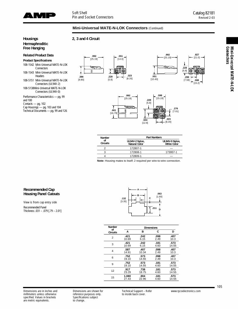
Soft ShellPin and Socket Connectors
Catalog 82181Revised 2-03
105
Mini-Universal MATE-N-LOK Connectors (Continued)
Dimensions are in inches and Dimensions are shown for Technical Support – Refer www.tycoelectronics.commillimeters unless otherwise reference purposes only. to inside back cover.specified. Values in brackets Specifications subjectare metric equivalents. to change.
2, 3 and 4 Circuit
Recommended CapHousing Panel Cutouts
View is from cap entry side
Recommended Panel Thickness .031 – .079 [.79 – 2.01]
Number Dimensionsof
Circuits A B C D
2 .421 .242 .098 .40710.69 6.15 2.49 10.3
3 .421 .242 .181 .57310.69 6.15 4.60 14.55
4 .587 .407 .098 .40714.91 10.34 2.49 10.3
6 .752 .573 .098 .40719.10 14.55 2.49 10.3
9 .752 .573 .181 .57319.10 14.55 4.60 14.55
12 .917 .738 .181 .57323.29 18.75 4.60 14.55
15 1.080 .904 .181 .57327.43 22.96 4.60 14.55
A
BC
D
.063[1.60]
.211
.992[25.19]
.992[25.19]
.228[5.8]
.228[5.8]
.992[25.19]
.661[16.79]
.299[7.59] .598
[15.2]
.276[7.01]
.504[12.8]
.827[21.0]
.551[14.0]
.228[5.8]
.323[8.20]
.323[8.20]
.386[9.80]
.551[10.40]
.598[15.19]
.132[3.35]
HousingsHermaphroditicFree Hanging
Related Product DataProduct Specifications108-1542 Mini-Universal MATE-N-LOK
Connectors108-1543 Mini-Universal MATE-N-LOK
Headers108-5151 Mini-Universal MATE-N-LOK
Connectors (UL94V-2)108-5138 Mini-Universal MATE-N-LOK
Connectors (UL94V-0)
Performance Characteristics — pg. 99and 100Contacts — pg. 102Cap Housings — pg. 103 and 104Technical Documents — pg. 99 and 126
Part NumbersNumberUL94V-2 Nylon, UL94V-0 Nylon,ofNatural Color White ColorCircuits
2 172807-1 —3 172808-1 173957-14 172809-1 —
Note: Housing mates to itself; 2 required per wire-to-wire connection.
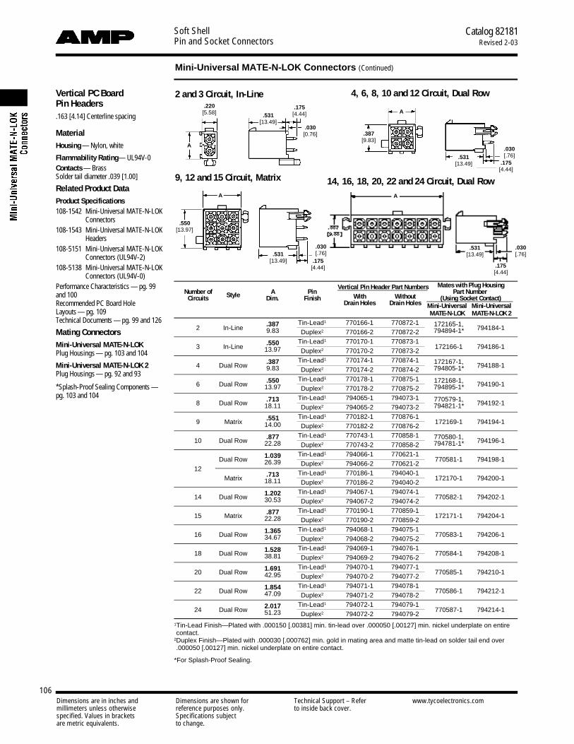
Soft ShellPin and Socket Connectors
Catalog 82181Revised 2-03
106
Mini-Universal MATE-N-LOK Connectors (Continued)
Dimensions are in inches and Dimensions are shown for Technical Support – Refer www.tycoelectronics.commillimeters unless otherwise reference purposes only. to inside back cover.specified. Values in brackets Specifications subjectare metric equivalents. to change.
Vertical PC Board Pin Headers.163 [4.14] Centerline spacing
MaterialHousing — Nylon, white
Flammability Rating— UL94V-0Contacts — BrassSolder tail diameter .039 [1.00]
Related Product DataProduct Specifications108-1542 Mini-Universal MATE-N-LOK
Connectors108-1543 Mini-Universal MATE-N-LOK
Headers108-5151 Mini-Universal MATE-N-LOK
Connectors (UL94V-2)108-5138 Mini-Universal MATE-N-LOK
Connectors (UL94V-0)Performance Characteristics — pg. 99and 100Recommended PC Board HoleLayouts — pg. 109Technical Documents — pg. 99 and 126
Mating ConnectorsMini-Universal MATE-N-LOKPlug Housings — pg. 103 and 104
Mini-Universal MATE-N-LOK 2Plug Housings — pg. 92 and 93
*Splash-Proof Sealing Components —pg. 103 and 104
2 and 3 Circuit, In-Line
9, 12 and 15 Circuit, Matrix
4, 6, 8, 10 and 12 Circuit, Dual Row.220
[5.58] .531[13.49]
.030[0.76] .387
[9.83]
.175[4.44]
.175[4.44]
.030[.76].531
[13.49]
.175[4.44]
.030[.76].531
[13.49]
A
A
A
.550[13.97]
Vertical Pin Header Part Numbers Mates with Plug HousingNumber of Style A Pin
With WithoutPart Number
Circuits Dim. FinishDrain Holes Drain Holes
(Using Socket Contact)Mini-Universal Mini-UniversalMATE-N-LOK MATE-N-LOK 2
2 In-Line .387 Tin-Lead1 770166-1 770872-1 172165-1, 794184-19.83 Duplex2 770166-2 770872-2 794894-1*
3 In-Line .550 Tin-Lead1 770170-1 770873-1172166-1 794186-113.97 Duplex2 770170-2 770873-2
4 Dual Row .387 Tin-Lead1 770174-1 770874-1 172167-1, 794188-19.83 Duplex2 770174-2 770874-2 794805-1*
6 Dual Row .550 Tin-Lead1 770178-1 770875-1 172168-1, 794190-113.97 Duplex2 770178-2 770875-2 794895-1*
8 Dual Row .713 Tin-Lead1 794065-1 794073-1 770579-1, 794192-118.11 Duplex2 794065-2 794073-2 794821-1*
9 Matrix .551 Tin-Lead1 770182-1 770876-1172169-1 794194-114.00 Duplex2 770182-2 770876-2
10 Dual Row .877 Tin-Lead1 770743-1 770858-1 770580-1, 794196-122.28 Duplex2 770743-2 770858-2 794781-1*
Dual Row 1.039 Tin-Lead1 794066-1 770621-1770581-1 794198-1
1226.39 Duplex2 794066-2 770621-2
Matrix .713 Tin-Lead1 770186-1 794040-1172170-1 794200-118.11 Duplex2 770186-2 794040-2
14 Dual Row 1.202 Tin-Lead1 794067-1 794074-1770582-1 794202-130.53 Duplex2 794067-2 794074-2
15 Matrix .877 Tin-Lead1 770190-1 770859-1172171-1 794204-122.28 Duplex2 770190-2 770859-2
16 Dual Row 1.365 Tin-Lead1 794068-1 794075-1770583-1 794206-134.67 Duplex2 794068-2 794075-2
18 Dual Row 1.528 Tin-Lead1 794069-1 794076-1770584-1 794208-138.81 Duplex2 794069-2 794076-2
20 Dual Row 1.691 Tin-Lead1 794070-1 794077-1770585-1 794210-142.95 Duplex2 794070-2 794077-2
22 Dual Row 1.854 Tin-Lead1 794071-1 794078-1770586-1 794212-147.09 Duplex2 794071-2 794078-2
24 Dual Row 2.017 Tin-Lead1 794072-1 794079-1770587-1 794214-151.23 Duplex2 794072-2 794079-2
1Tin-Lead Finish—Plated with .000150 [.00381] min. tin-lead over .000050 [.00127] min. nickel underplate on entirecontact.
2Duplex Finish—Plated with .000030 [.000762] min. gold in mating area and matte tin-lead on solder tail end over.000050 [.00127] min. nickel underplate on entire contact.
*For Splash-Proof Sealing.
A
14, 16, 18, 20, 22 and 24 Circuit, Dual Row
.175[4.44]
.030[.76]
.531[13.49]

Soft ShellPin and Socket Connectors
Catalog 82181Revised 2-03
107
Mini-Universal MATE-N-LOK Connectors (Continued)
Dimensions are in inches and Dimensions are shown for Technical Support – Refer www.tycoelectronics.commillimeters unless otherwise reference purposes only. to inside back cover.specified. Values in brackets Specifications subjectare metric equivalents. to change.
Vertical PC Board Blindmate Pin Headers.163 [4.14] Centerline spacing
MaterialHousing — Nylon, white
Flammability Rating— UL94V-0Contacts — BrassSolder tail diameter .039 [1.00]
Related Product DataProduct Specifications1 0 8 - 1 6 9 3 Mini-Universal MATE-N-LOK 2
C o n n e c t o r s1 0 8 - 1 6 9 4 Mini-Universal MATE-N-LOK 2
H e a d e r sPerformance Characteristics — pg. 99and 100Recommended PC Board HoleLayouts —pg. 109Technical Documents — pg. 99 and 126
Mating ConnectorsMini-Universal MATE-N-LOKPlug Housings—pg. 103 and 104
Mini-Universal MATE-N-LOK 2Plug Housings—pg. 92 and 93
9, 12 and 15 Circuit, Matrix
4, 6, 8 and 10 Circuit, Dual Row
Mates with Plug HousingNumber of
StyleA Pin Pin Header Part Numbers Part Number
Circuits Dim. Finish With Drain Holes (Using Socket Contacts)Mini-Universal Mini-UniversalMATE-N-LOK MATE-N-LOK 2
4 Dual Row .645 Tin-Lead1 794325-1172167-1 794188-116.38 Duplex2 794325-2
6 Dual Row .808 Tin-Lead1 794326-1172168-1 794190-120.52 Duplex2 794326-2
8 Dual Row .971 Tin-Lead1 794327-1770579-1 794192-124.66 Duplex2 794327-2
9 Matrix .808 Tin-Lead1 794432-1172169-1 794194-120.52 Duplex2 794432-2
10 Dual Row 1.134 Tin-Lead1 794328-1770580-1 794196-128.80 Duplex2 794328-2
12 Matrix .971 Tin-Lead1 794329-1172170-1 794200-124.66 Duplex2 794329-2
15 Matrix 1.134 Tin-Lead1 794330-1172171-1 794204-128.80 Duplex2 794330-2
1Tin-Lead Finish—Plated with .000150 [.00381] min. tin-lead over .000050 [.00127] min. nickel underplate on entirecontact.
2Duplex Finish—Plated with .000030 [.000762] min. gold in mating area and matte tin-lead on solder tail end over.000050 [.00127] min. nickel underplate on entire contact.

Soft ShellPin and Socket Connectors
Catalog 82181Revised 2-03
108
Mini-Universal MATE-N-LOK Connectors (Continued)
Dimensions are in inches and Dimensions are shown for Technical Support – Refer www.tycoelectronics.commillimeters unless otherwise reference purposes only. to inside back cover.specified. Values in brackets Specifications subjectare metric equivalents. to change.
Right-Angle PC BoardPin Headers.163 [4.14] Centerline spacing
MaterialHousing — Nylon, white color
Flammability Rating — UL94V-0
Contacts — Brass
Solder tail diameter .039 [1.00]
Related Product DataProduct Specification108-1694 Mini-Universal MATE-N-LOK
Headers
Performance Characteristics — pg. 99and 100Recommended PC Board HoleLayouts — pg. 109Technical Documents — pg. 99 and 126
Mating ConnectorsMini-Universal MATE-N-LOKPlug Housings—pg. 103 and 104
Mini-Universal MATE-N-LOK 2Plug Housings—pg. 92 and 93
*Splash-Proof Sealing Components —pg. 103 and 104
With Board Lock Feature1, 2 and 3 Circuit, In-Line 4, 6, 8, 10 and 12 Circuit, Dual Row
14, 16, 18, 20, 22 and 24 Circuit, Dual Row
Pin HeaderMates with Plug Housing
Number of A Pin Part NumberPart Number
Circuits Style Dim. Finish With Board Lock(Using Socket Contacts)
Mini-Universal Mini-UniversalMATE-N-LOK MATE-N-LOK 2
1 — .225 Tin-Lead1 794374-1172164-1 —5.72 Duplex2 794374-2
2 In-Line .388 Tin-Lead1 770966-1 172165-1, 794184-19.86 Duplex2 770966-2 794894-1*
3 In-Line .551 Tin-Lead1 770967-1172166-1 794186-114.00 Duplex2 770967-2
4 Dual Row .388 Tin-Lead1 770968-1 172167-1, 794188-19.86 Duplex2 770968-2 794805-1*
6 Dual Row .551 Tin-Lead1 770969-1 172168-1, 794190-114.00 Duplex2 770969-2 794895-1*
8 Dual Row .714 Tin-Lead1 770970-1 770579-1, 794192-118.14 Duplex2 770970-2 794821-1*
10 Dual Row .877 Tin-Lead1 770971-1 770580-1, 794196-122.28 Duplex2 770971-2 794781-1*
12 Dual Row 1.040 Tin-Lead1 770972-1770581-1 794198-126.42 Duplex2 770972-2
14 Dual Row 1.203 Tin-Lead1 770973-1770582-1 794202-130.56 Duplex2 770973-2
16 Dual Row 1.366 Tin-Lead1 770974-1770583-1 794206-134.70 Duplex2 770974-2
18 Dual Row 1.529 Tin-Lead1 794105-1770584-1 794208-138.84 Duplex2 794105-2
20 Dual Row 1.692 Tin-Lead1 794106-1770585-1 794210-142.98 Duplex2 794106-2
22 Dual Row 1.855 Tin-Lead1 794107-1770586-1 794212-147.12 Duplex2 794107-2
24 Dual Row 2.018 Tin-Lead1 794108-1770587-1 794214-151.26 Duplex2 794108-2
1Tin-Lead Finish—Plated with .000150 [.00381] min. tin-lead over .000050 [.00127] min. nickel underplate on entirecontact.
2Duplex Finish—Plated with .000030 [.000762] min. gold in mating area and matte tin-lead on solder tail end over.000050 [.00127] min. nickel underplate on entire contact.
*For Splash-Proof Sealing.

Soft ShellPin and Socket Connectors
Catalog 82181Revised 2-03
109
Mini-Universal MATE-N-LOK Connectors (Continued)
Dimensions are in inches and Dimensions are shown for Technical Support – Refer www.tycoelectronics.commillimeters unless otherwise reference purposes only. to inside back cover.specified. Values in brackets Specifications subjectare metric equivalents. to change.
2 and 3 Circuit, In-Line
9, 12 and 15 Circuit, Matrix
4, 6, 8, 10 and 12 Circuit, Dual Row
14, 16, 18, 20, 22 and 24 Circuit, Dual Row
Recommended PC BoardHole Layouts for Vertical and Blindmate Headers.062 [1.57] thick board, tolerances non-accumulative
Related Product DataVertical Headers — pg. 106 and 107
22 Circuit, Dual Row
14 and 18 Circuit, Dual Row
16, 20 and 24 Circuit, Dual Row
4, 8 and 12 Circuit, Dual Row
2 Circuit, In-Line1 Circuit 3 Circuit, In-Line
6 and 10 Circuit, Dual Row
Recommended PC BoardHole Layouts for Right-Angle Headers.062 [1.57] thick board, tolerances non-accumulative
Related Product DataRight-Angle Headers — pg. 108

Soft ShellPin and Socket Connectors
Catalog 82181Revised 2-03
110
Mini-Universal MATE-N-LOK Connectors (Continued)
Dimensions are in inches and Dimensions are shown for Technical Support – Refer www.tycoelectronics.commillimeters unless otherwise reference purposes only. to inside back cover.specified. Values in brackets Specifications subjectare metric equivalents. to change.
Close and Lock Strain Reliefaround housing.Insert Locking Tab to firmlysecure wires.
Step 1
Step 2
Strain Reliefs for Plug or Cap Housings
Related Product DataHousings — pg. 103 and 104Technical Documents — pg. 99 and 126
These Strain Reliefs may also be usedwith AMP-DUAC Receptacle housings.
6 and 8 Circuit
Style Number of A Wire Bundle Part NumbersCircuits Dim. Dia. Range UL94V-0 Nylon, White Color
6 .920 .165-.220 794423-1Dual Row
23.36 4.19-5.59
8 .920 .180-.245 794370-123.36 4.57-6.22
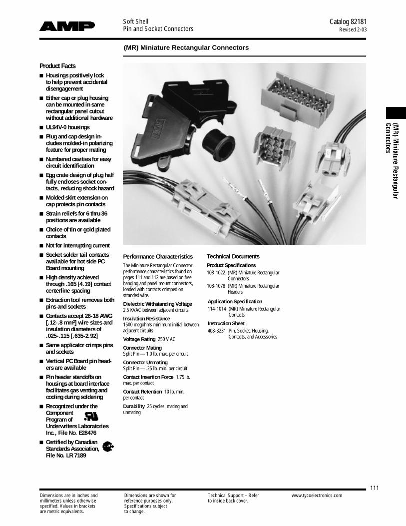
Soft ShellPin and Socket Connectors
Catalog 82181Revised 2-03
111
(MR) Miniature Rectangular Connectors
Dimensions are in inches and Dimensions are shown for Technical Support – Refer www.tycoelectronics.commillimeters unless otherwise reference purposes only. to inside back cover.specified. Values in brackets Specifications subjectare metric equivalents. to change.
Performance CharacteristicsThe Miniature Rectangular Connectorperformance characteristics found onpages 111 and 112 are based on freehanging and panel mount connectors,loaded with contacts crimped onstranded wire.
Dielectric Withstanding Voltage2.5 KVAC between adjacent circuits
Insulation Resistance1500 megohms minimum initial between adjacent circuits
Voltage Rating 250 V AC
Connector MatingSplit Pin — 1.0 lb. max. per circuit
Connector UnmatingSplit Pin — .25 lb. min. per circuit
Contact Insertion Force 1.75 lb.max. per contact
Contact Retention 10 lb. min. per contact
Durability 25 cycles, mating and unmating
Application Specification114-1014 (MR) Miniature Rectangular
Contacts
Instruction Sheet408-3231 Pin, Socket, Housing,
Contacts, and Accessories
Product Facts■ Housings positively lock
to help prevent accidentald i s e n g a g e m e n t
■ Either cap or plug housingcan be mounted in samerectangular panel cutoutwithout additional hardware
■ UL94V-0 housings
■ Plug and cap design in-cludes molded-in polarizingfeature for proper mating
■ Numbered cavities for easycircuit identification
■ Egg crate design of plug halffully encloses socket con-tacts, reducing shock hazard
■ Molded skirt extension oncap protects pin contacts
■ Strain reliefs for 6 thru 36positions are available
■ Choice of tin or gold platedc o n t a c t s
■ Not for interrupting current
■ Socket solder tail contactsavailable for hot side P CBoard mounting
■ High density achievedthrough .165 [4.19] contactcenterline spacing
■ Extraction tool removes bothpins and sockets
■ Contacts accept 26-18 AWG[.12-.8 mm2] wire sizes andinsulation diameters of .025-.115 [.635-2.92]
■ Same applicator crimps pinsand sockets
■ Vertical PC Board pin head-ers are available
■ Pin header standoffs onhousings at board interfacefacilitates gas venting andcooling during soldering
■ Recognized under theComponent Program of Underwriters LaboratoriesInc., File No. E28476
■ Certified by CanadianStandards Association,File No. LR 7189
Technical DocumentsProduct Specifications108-1022 (MR) Miniature Rectangular
Connectors108-1078 (MR) Miniature Rectangular
Headers

Soft ShellPin and Socket Connectors
Catalog 82181Revised 2-03
112
(MR) Miniature Rectangular Connectors (Continued)
Dimensions are in inches and Dimensions are shown for Technical Support – Refer www.tycoelectronics.commillimeters unless otherwise reference purposes only. to inside back cover.specified. Values in brackets Specifications subjectare metric equivalents. to change.
PerformanceCharacteristics(Continued)
Maximum Current Maximum currentrating of Miniature Rectangular connec-tors is limited by the maximum operat-ing temperature of the housings which is105°C including the temperature rise ofthe contacts which is a maximum of30°C. There are several variables whichhave a direct effect on this maximumcurrent-carrying capability for a givenconnector and must be considered foreach application. These variables are:
Wire Size Larger diameter wire willcarry more current since it has less in-ternal resistance to current flow and thusgenerates less heat. Longer wire lengthsalso enhance current-carrying capabili-ties since the wire conducts heat awayfrom the connector.
Connector Size In general, the morecircuits in a connector, the less currentcan be carried.
Ambient Temperature The higherthe ambient temperature, the less currentcan be carried in any given connector.
Printed Wiring Board ConductorSize The finished trace conductor widthand thickness should be maximized toallow for the greatest current-carryingcapacity and heat dissipation.
Miniature Rectangular connectors alsowill withstand the following tests:
Vibration 10-55-10 cycles per minuteat .06 inch total excursion
Physical Shock 18 drops, 50 G saw-tooth at 10 milliseconds
Housing Panel Retention 50 lb. min.
Housing Lock Strength 20 lb. min.
Thermal Shock 255°C to 185°C
Temperature-Humidity Cycling25°C to 65°C at 95 RH
Corrosion 48 hr. at 5% salt concentration
Related Product DataProduct Specifications108-1022 (MR) Miniature Rectangular
Connectors108-1078 (MR) Miniature Rectangular
Headers
Current Rating Verification for 308C Maximum Temperature Rise 100% Energized
Wire-to-WireMR Calculated Current Table
Number of Wire GaugeCircuits 18 20 22 24 26
2 9.00 8.00 6.50 5.50 5.003 8.50 7.00 6.00 5.00 4.504 7.00 6.50 5.50 5.00 4.006 6.00 6.00 5.00 4.00 4.009 5.00 5.00 4.00 4.00 3.5012 4.50 4.50 4.00 3.50 3.0015 4.50 4.00 3.50 3.00 2.5020 4.00 4.00 3.50 3.00 2.5024 4.00 3.50 3.00 2.50 2.0036 3.50 3.00 2.50 2.00 2.00
Values are based on initial Temperature Rise versus Current Testing and are intended to be a guide in the selection of a connector family. All applications should be tested by the end user. The values listed are per circuit for fully loadedhousings being 100% energized. Note: All combinations were not tested and this chart contains interpolated and extrapolated values.
Termination Resistance/Contact Crimp Tensile Force
Termination ContactResistance Crimp
Wire SizeTest Resistance
Tensile ForceAWG mm2
Current Milliohms Force (Min.)(Amps) (Max. Init.) lbs. N
26 .12 1 5.00 5 2224 .2 1.5 5.00 8 3622 .3 3 4.50 14 6220 .5 4.5 4.00 14 6218 .8 6 4.00 30 133
N o t e: This is the total resistance between wire crimps of a mated pin and socket.
Wire-to-BoardDue to the vast differences in trace geometry and printed circuit board configurations, we are unable to provide a sep-arate current carrying chart for our printed circuit board header products. However, the above Wire-to-Wire charts maybe used as a guideline for headers if the trace width and thickness is equal to the listed wire guage. For vertical head-ers, only 95% of the Wire-to-Wire value should be used. For right-angle headers, only 75% of the Wire-to-Wire valueshould be used. The charted values are only a tool for connector selection and will require the customer to fully testtheir application.
Minimum Wire Lengths for T-Rise vs. Current TestingAWG Min. Length (in.) AWG Min. Length (in.)30 2.6 18 9.428 3.2 16 11.326 4.1 14 13.724 5.1 12 16.420 7.8 10 19.3
Note: If wire lengths used are less than those listed above, the current-carrying ability of the system will be reduced due to less heat beingconducted away from the connector. The customer should fully test all applications.

Soft ShellPin and Socket Connectors
Catalog 82181Revised 2-03
113
(MR) Miniature Rectangular Connectors (Continued)
Dimensions are in inches and Dimensions are shown for Technical Support – Refer www.tycoelectronics.commillimeters unless otherwise reference purposes only. to inside back cover.specified. Values in brackets Specifications subjectare metric equivalents. to change.
(MR) Miniature Rectangular Connector Mating CombinationsConnector Part Number Mating Connector Part Number
Number Flammability Pin Housing Socket Housing PC Boardof Style (Cap) (Plug) Vertical Pin Headers
Circuits Rating Part No. Part No. Plating .062 Board .120 BoardTin 640497-1 640497-3
2 UL94V-0 In-Line 1-640507-0 1-640517-0Duplex1 640497-2 640497-4
Tin 640498-1 640498-33 UL94V-0 In-Line 1-640508-0 1-640518-0
Duplex1 640498-2 640498-4Tin 640499-1 640499-3
4 UL94V-0 Matrix 1-640509-0 1-640519-0Duplex1 640499-2 640499-4
Tin 640500-1 640500-36 UL94V-0 Matrix 1-640510-0 1-640520-0
Duplex1 640500-2 640500-4Tin 640501-1 640501-3
9 UL94V-0 Matrix 1-640511-0 1-640521-0Duplex1 640501-2 640501-4
Tin 640502-1 640502-312 UL94V-0 Matrix 1-640512-0 1-640522-0
Duplex1 640502-2 640502-4Tin 640503-1 640503-3
15 UL94V-0 Matrix 1-640513-0 1-640523-0Duplex1 640503-2 640503-4
Tin 640504-1 640504-320 UL94V-0 Matrix 1-640514-0 1-640524-0
Duplex1 640504-2 640504-4Tin 640505-1 640505-3
24 UL94V-0 Matrix 1-640515-0 1-640525-0Duplex1 640505-2 640505-4
Tin 640506-1 640506-336 UL94V-0 Matrix 1-640516-0 1-640526-0
Duplex1 640506-2 640506-4
1Duplex Finish—Plated with .000030 [.000762] min. gold in mating area, matte tin on solder tail end over .000050 [.00127] min. nickel underplate on entirecontact.

Soft ShellPin and Socket Connectors
Catalog 82181Revised 2-03
114
(MR) Miniature Rectangular Connectors (Continued)
Dimensions are in inches and Dimensions are shown for Technical Support – Refer www.tycoelectronics.commillimeters unless otherwise reference purposes only. to inside back cover.specified. Values in brackets Specifications subjectare metric equivalents. to change.
ContactsPin diameter .068 [1.73]
M a t e r i a lPhosphor bronzeStock thickness .008 [.203]
Contact Extraction ToolNo. 455822-2IS 408-9570
Recommended PC Board Hole Layout.062 [1.57] or .093 [2.36] thick board
Contact Insertion Tool(For inserting contacts applied to small diameter wire)
No. 455830-1IS 408-7984
Live Split Pin
Related Product DataProduct Specification108-1022 (MR) Miniature Rectangular
ConnectorsApplication Specification114-1014 (MR) Miniature Rectangular
Contacts
Performance Characteristics —pg. 111 and 112Housings — pg. 115 and 116Technical Documents — pg. 111 and 126Application Tooling — pg. 127-130 and1 3 2
Grounding Pin(Mate first, break last, not for interruptingcurrent)
Pin diameter .068 [1.73]Stock thickness .008 [.203]
M a t e r i a lPhosphor Bronze
Keying PlugIS 408-3231
Solder Tail SocketMaterial and FinishPhosphor bronze, pre-tinStock thickness .008 [.203]
Wire SizeIns. Dia.
Contact Part Numbers HDM Hand ToolRangeRange
Finish Live Split Pin Standard Socket Applicator Part No.AWG [mm2] Strip Form Loose Form Strip Form Loose Form Part No.
26-24 .025-.050 Pre-tin 350968-1 640579-1 794000-1 794001-1 466352-13
466352-23 91534-1[.12-.2] .635-1.27 Select Gold1 350968-2 640579-2 794000-2 794001-2 466352-33
26-182 .050-.115 Pre-tin 350967-1 640545-1 641294-1 641300-1 466351-13
466351-23 91526-1[.12-.8] 1.27-2.92 Select Gold1 350967-2 640545-2 641294-2 641300-2 466351-43
1Select Gold Finish—Plated with .000030 min. [.000762] gold in mating area over .000050 [.00127] min. nickel underplate on entire contact.21650 CMA maximum.3HDM Applicator part number ending in -1 is used on AMPOMATOR CLS Machine with T or G Terminators, -2 is used on AMP-O-LECTRIC Model K Machine,-3 or -4 is used on AMP-O-LECTRIC Model G Machine. See page 132 for further information.
Wire Size Ins. Dia. Grounding Pin Part Numbers HDM Hand ToolR a n g e R a n g e F i n i s h A p p l i c a t o r Part No.AWG [mm2] Strip Form Loose Form Part No.
26-182 .050-.115 Pre-tin 350969-1 640580-1 466351-13
466351-23 91526-1[.12-.8] 1.27-2.92 Select Gold1 350969-2 640580-2 466351-43
1Select Gold Finish — Plated with .000030 [.000762] min. gold in mating area over .000050[.00127] min. nickel underplate on entire contact.
21650 CMA maximum.3HDM Applicator part number ending in -1 is used on AMPOMATOR CLS Machine with T or G Terminators, -2 is used on AMP-O-LECTRIC Model K Machine, -3 or -4 is used on AMP-O-LECTRIC Model G Machine. See page 132 for further information.
.790[20.06]
.850[21.59]
1.00[25.4]
.970[24.63]
.165[4.19]
Typ.
.165[4.19]
Typ.
.055[1.39]
Dia. Typ.
Part Number 350838-1Note: Recommended for use with
MR Socket Housings
Part Number 350591-1UL94V-0 Nylon material
Note: Use in socket housings only.
.660[16.76]
Standard Socket

Soft ShellPin and Socket Connectors
Catalog 82181Revised 2-03
115
(MR) Miniature Rectangular Connectors (Continued)
Dimensions are in inches and Dimensions are shown for Technical Support – Refer www.tycoelectronics.commillimeters unless otherwise reference purposes only. to inside back cover.specified. Values in brackets Specifications subjectare metric equivalents. to change.
HousingsFree Hanging or Panel Mount.165 [4.19] Centerline spacing
MaterialNylon, Natural (Color—Brick Red)
Flammability Rating — UL94V-0
Related Product DataProduct Specification108-1022 (MR) Miniature Rectangular
Connectors
Performance Characteristics —pg. 111 and 112P a n e lC u t o u tR e c o m m e n d a t i o ns —p g. 1 1 7Contacts — pg. 114Keying Plug — pg. 114Strain Reliefs — pg. 118Commoning Bars — pg. 118Technical Documents — p g . 111 and 126Mating Headers — pg. 119 and 120
2 and 3 Circuit,In-Line
4 and 6 Circuit,Matrix
Socket Housing (Plug)
Pin Housing (Cap)
Number of Dimensions Part NumbersCircuits A B C Pin Housing (Cap) Socket Housing (Plug)
2 .455 .365 .755 1-640507-0 1-640517-011.56 9.27 19.18
3 .620 .530 .920 1-640508-0 1-640518-015.75 13.46 23.37
Number of A Part NumbersCircuits Dim. Pin Housing (Cap) Socket Housing (Plug)
4 .45511.56 1-640509-0 1-640519-0
6 .620 1-640510-0 1-640520-015.75
Typical CircuitIdentification
Typical CircuitIdentification
Positive LockingDevice
Positive LockingDevice
A
A
1.060[26.92]
.435[11.05]
.755[19.18]
.755[19.18]
.840[21.34]
.365[9.27]
.455[19.18]
Fingergrip
.510[12.95]
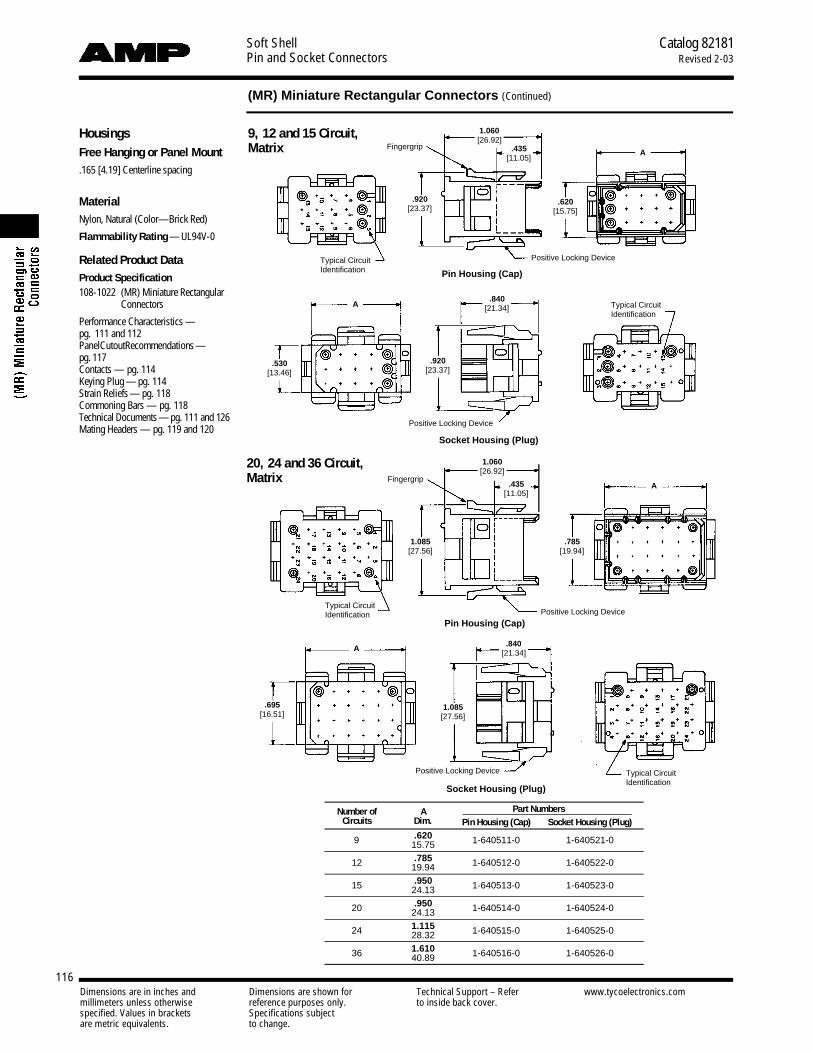
Soft ShellPin and Socket Connectors
Catalog 82181Revised 2-03
116
(MR) Miniature Rectangular Connectors (Continued)
Dimensions are in inches and Dimensions are shown for Technical Support – Refer www.tycoelectronics.commillimeters unless otherwise reference purposes only. to inside back cover.specified. Values in brackets Specifications subjectare metric equivalents. to change.
HousingsFree Hanging or Panel Mount.165 [4.19] Centerline spacing
MaterialNylon, Natural (Color—Brick Red)
Flammability Rating — UL94V-0
Related Product DataProduct Specification108-1022 (MR) Miniature Rectangular
Connectors
Performance Characteristics —pg. 111 and 112P a n e lC u t o u tR e c o m m e n d a t i o ns —p g. 1 1 7Contacts — pg. 114Keying Plug — pg. 114Strain Reliefs — pg. 118Commoning Bars — pg. 118Technical Documents — p g . 111 and 126Mating Headers — pg. 119 and 120
20, 24 and 36 Circuit,Matrix
Pin Housing (Cap)
Pin Housing (Cap)
Socket Housing (Plug)
Socket Housing (Plug)
9, 12 and 15 Circuit,Matrix
Number of A Part NumbersCircuits Dim. Pin Housing (Cap) Socket Housing (Plug)
9 .620 1-640511-0 1-640521-015.75
12 .785 1-640512-0 1-640522-019.94
15 .950 1-640513-0 1-640523-024.13
20 .950 1-640514-0 1-640524-024.13
24 1.115 1-640515-0 1-640525-028.32
36 1.610 1-640516-0 1-640526-040.89
Typical CircuitIdentification
Typical CircuitIdentification
Typical CircuitIdentification
Typical CircuitIdentification
Fingergrip
Fingergrip
Positive Locking Device
Positive Locking Device
Positive Locking Device
Positive Locking Device
1.060[26.92]
1.060[26.92]
.920[23.37]
.920[23.37]
.840[21.34]
.840[21.34]
.620[15.75]
.530[13.46]
.435[11.05]
.435[11.05]
1.085[27.56]
1.085[27.56]
.785[19.94]
.695[16.51]
A
A
A
A

Soft ShellPin and Socket Connectors
Catalog 82181Revised 2-03
117
(MR) Miniature Rectangular Connectors (Continued)
Dimensions are in inches and Dimensions are shown for Technical Support – Refer www.tycoelectronics.commillimeters unless otherwise reference purposes only. to inside back cover.specified. Values in brackets Specifications subjectare metric equivalents. to change.
Recommended PanelCutouts for Pin and SocketHousings
Related Product DataProduct Specification108-1022 (MR) Miniature Rectangular
ConnectorsHousings — pg. 115 and 116Technical Documents — pg. 111 and 126
Notes:1. When mounted in a .060 [1.52] thick panel, the cap’s mating end extends .800 [20.32] beyond the panel front; wire
end extends .220 [55.88] from the panel rear. Plug mating end extends .580 [14.73] beyond the panel front; wireend extends .220 [55.88] from the panel rear.
2. The panel should be punched so that the housing enters the panel in the same direction as the punch for ease ofassembly.
Number of Panel Cutout DimensionsCircuits A B C D E F
2 .105 .220 .475 .630 .785 .4302.67 5.59 12.07 16.00 19.94 10.92
3 .105 .220 .640 .795 .950 .4302.67 5.59 16.26 20.19 24.13 10.92
4 .157 .280 .475 .630 .785 .5953.99 5.28 12.07 16.00 19.94 15.11
6 .208 .345 .475 .630 .785 .7605.28 8.76 12.07 16.00 19.94 19.30
9 .208 .345 .640 .795 .950 .7605.28 8.76 16.26 20.19 24.13 19.30
12 .225 .475 .640 .795 .950 .9255.72 12.07 16.26 20.19 24.13 23.50
15 .308 .475 .640 .795 .950 1.0907.82 12.07 16.26 20.19 24.13 27.69
20 .308 .475 .805 .960 1.115 1.0907.82 12.07 20.45 24.38 28.32 27.69
24 .390 .475 .805 .960 1.115 1.2559.91 12.07 20.45 24.38 28.32 31.88
36 .625 .500 .800 .950 1.100 1.75015.86 12.70 20.32 24.13 27.94 44.45
A
C
D
E
B
F
View is from housing entry side
Panel Thickness .068 [1.75] Max.

Soft ShellPin and Socket Connectors
Catalog 82181Revised 2-03
118
(MR) Miniature Rectangular Connectors (Continued)
Dimensions are in inches and Dimensions are shown for Technical Support – Refer www.tycoelectronics.commillimeters unless otherwise reference purposes only. to inside back cover.specified. Values in brackets Specifications subjectare metric equivalents. to change.
Strain ReliefsOne Piece — Clam Shell(Illustrated in closed position)IS 408-3231
MaterialNylon, Natural (Color—Brick Red)
Flammability Rating — UL94V-0
6, 9, 12, 15 and 20 Circuit 24 and 36 Circuit
Strain ReliefAdapting GrommetsIS 408-3231
MaterialFlexible PVC (55/75 Durometer) blackcolor
Number of Dimensions PartCircuits I.D. A B C Numbers
6 .374 .634 .760 1.000 350373-19.50 16.10 19.30 25.4
9 .420 .800 .760 1.000 350522-110.67 20.32 19.30 25.4
12 .420 .790 .925 1.000 350374-110.67 20.07 23.50 25.4
15 .420 .790 1.090 1.000 350523-110.67 20.07 27.69 25.4
20 .560 .960 1.090 1.280 480634-114.22 24.38 27.69 23.51
24 .560 .900 1.255 1.280 350524-114.22 22.86 31.88 23.51
36 .560 .900 1.750 1.280 480594-114.22 22.86 44.45 23.51
Notes:1. These strain reliefs can be used with either pin or socket housings.2. Customer supplied: One No. 6 Panhead Type B self-taping screw,
3/8 long. Plating is optional to conform to customer requirements.3. Strain reliefs are also available in UL94V-2 nylon, black in color. To order
strain reliefs in this material use the appropriate dash numbers: 1-XXXXXX-9.
Number of Dimensions PartCircuits I.D. A B Numbers
.156 .375 .375 1-350377-03.96 9.53 9.53
6 .218 .375 .375 1-350376-05.54 9.53 9.53.296 .375 .375 1-350375-07.52 9.53 9.53.218 .375 .420 1-350378-15.54 9.53 10.67
9, 12 .250 .375 .420 1-350379-1& 15 6.35 9.53 10.67.281 .375 .420 1-350380-17.14 9.53 10.67.437 .500 .562 1-380935-011.10 12.70 14.27
20, 24 .375 .500 .562 1-380936-0& 36 9.53 12.70 14.27.312 .500 .562 1-380937-07.92 12.70 14.27
A A
AC CB B
BI.D. I.D.
I.D.
Hinge Hinge
Commoning BarsIS 408-3231
MaterialBrassStock thickness .008 [.203]
Commoning Bar Extraction ToolNo. 457306-1IS 408-3231
Notes:1. Commoning bars can be used to common adjacent pin contacts in any column or row. Maximum
stack per pin is two.2. The above illustrates the proper insertion of the Commoning Bar.3. Use the mating socket housing to assemble the Commoning Bar onto the pins.
FinishPart Numbers
2 Circuit 3 Circuit 4 CircuitPre-tin 350020-1 350021-1 350022-1Gold1 350020-2 350021-2 350022-2
1Gold Finish — Plated with .000030 [.000762] min. gold over .000050[.00127] min. nickel underplate on entire contact.
DoubleStack
CommoningBar
Pin
4 Circuit .635[16.12]
3 Circuit .470[11.93]
2 Circuit .305[7.74]
Related Product DataHousings — pg. 115 and 116

Soft ShellPin and Socket Connectors
Catalog 82181Revised 2-03
119
(MR) Miniature Rectangular Connectors (Continued)
Dimensions are in inches and Dimensions are shown for Technical Support – Refer www.tycoelectronics.commillimeters unless otherwise reference purposes only. to inside back cover.specified. Values in brackets Specifications subjectare metric equivalents. to change.
PC Board VerticalPin Headers.165 [4.19] Centerline spacing
MaterialHousing — Nylon, Natural (Color—Brick Red)
Flammability Rating — UL94V-0
Contacts — Phosphor bronzeSolder tail diameter .040 [1.02]
Related Product DataProduct Specification108-1078 (MR) Miniature Rectangular
HeadersDimensions A and B — pg. 120Performance Characteristics — pg. 111and 112Technical Documents — pg. 111 and 126Mating Socket Housings — pgs. 115and 116
Recommended PC Board Hole Layout
Recommended PC Board Hole Layout
2 and 3 Circuit, In-Line
4 and 6 Circuit, Matrix
.530[13.46]
.455[11.56]
.290[7.36]
.165[4.19]
.165[4.19]
.150[3.81]
.150[3.81]
.530[13.46]
.435[11.05]
.435[11.05]
.030[.762]
.030[.762]
Live Pin
Live Pin
Typ.
B
A
A
B
.055[1.40]
Dia. Typ.
.055[1.40] Dia. Typ.
9, 12 and 15 Circuit, Matrix
Recommended PC Board Hole Layout
.530[13.46]
.030[.762]
.435[11.05]B
ADia. Typ..055
[1.40]
Typ.
.150[3.81]
.620[15.75]
.165[4.19]
.165[4.19]
Live Pin
.165[4.19]
Typ.
Typ.

Soft ShellPin and Socket Connectors
Catalog 82181Revised 2-03
120
(MR) Miniature Rectangular Connectors (Continued)
Dimensions are in inches and Dimensions are shown for Technical Support – Refer www.tycoelectronics.commillimeters unless otherwise reference purposes only. to inside back cover.specified. Values in brackets Specifications subjectare metric equivalents. to change.
20, 24 and 36 Circuit, Matrix
Recommended PC Board Hole Layout
.530[13.46]
.030[.76]
.435[11.05]
.785[19.94]
B
A .055[1.40] Dia. Typ.
.150[3.81]
.165[4.19]Typ.
.165[4.19]Typ.
Live Pin
Number Board Dimensions Header Part Numbers Mates withof Tin Duplex Socket Housing
Circuits Thickness A B Finish Finish1 Part No.
.062 .455 .120 640497-1 640497-22 1.57 11.56 3.051-640517-0In-Line .120 .455 .180 640497-3 640497-43.05 11.56 4.57
.062 .620 .120 640498-1 640498-23 1.57 15.75 3.051-640518-0
In-Line .120 .620 .180 640498-3 640498-43.05 15.75 4.57.062 .455 .120 640499-1 640499-2
41.57 11.56 3.05
1-640519-0.120 .455 .180 640499-3 640499-43.05 11.55 4.57.062 .620 .120 640500-1 640500-2
61.57 15.75 3.05
1-640520-0.120 .620 .180 640500-3 640500-43.05 15.75 4.57.062 .620 .120 640501-1 640501-2
91.57 15.75 3.05
1-640521-0.120 .620 .180 640501-3 640501-43.05 15.75 4.57.062 .785 .120 640502-1 640502-2
121.57 19.94 3.05
1-640522-0.120 .785 .180 640502-3 640502-43.05 19.94 4.57.062 .950 .120 640503-1 640503-2
151.57 24.13 3.05
1-640523-0.120 .950 .180 640503-3 640503-43.05 24.13 4.57.062 .950 .120 640504-1 640504-2
201.57 24.13 3.05
1-640524-0.120 .950 .180 640504-3 640504-43.05 24.13 4.57.062 1.115 .120 640505-1 640505-2
241.57 28.32 3.05
1-640525-0.120 1.115 .180 640505-3 640505-43.05 28.32 4.57.062 1.610 .120 640506-1 640506-2
361.57 40.89 3.05
1-640526-0.120 1.610 .180 640506-3 640506-43.05 40.89 4.57
1Duplex Finish—Plated with .000030 [.000762] min. gold in mating area, matte tin on solder tail end over .000050 [.00127] min. nickel underplate on entire contact.
PC Board VerticalPin Headers.165 [4.19] Centerline spacing
MaterialHousing — Nylon, Natural (Color–Brick Red)
Flammability Rating — UL94V-0
Contacts — Phosphor bronzeSolder tail diameter .040 [1.02]
Related Product DataProduct Specification108-1078 (MR) Miniature Rectangular
HeadersDimensions (2 and 3 Circuit, In-Line; 4,6, 9, 12 and 15 Circuit, Matrix) —pg.119Performance Characteristics — pg. 111and 112Vertical Pin Headers and RecommendedPC Board Hole Layouts — pgs. 119 and120 Technical Documents — pg. 111 and 126Mating Socket Housings — pgs. 115and 116
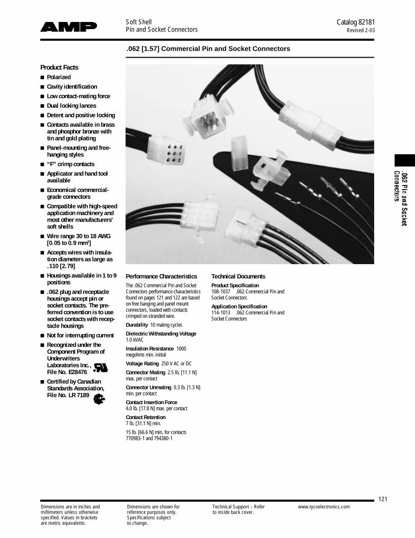
Soft ShellPin and Socket Connectors
Catalog 82181Revised 2-03
121
.062 [1.57] Commercial Pin and Socket Connectors
Dimensions are in inches and Dimensions are shown for Technical Support – Refer www.tycoelectronics.commillimeters unless otherwise reference purposes only. to inside back cover.specified. Values in brackets Specifications subjectare metric equivalents. to change.
Product Facts■ Polarized
■ Cavity identification
■ Low contact-mating force
■ Dual locking lances
■ Detent and positive locking
■ Contacts available in brassand phosphor bronze withtin and gold plating
■ Panel-mounting and free-hanging styles
■ “F” crimp contacts
■ Applicator and hand toolavailable
■ Economical commercial-grade connectors
■ Compatible with high-speedapplication machinery andmost other manufacturers’soft shells
■ Wire range 30 to 18 AWG[0.05 to 0.9 mm2]
■ Accepts wires with insula-tion diameters as large as.110 [2.79]
■ Housings available in 1 to 9positions
■ .062 plug and receptaclehousings accept pin orsocket contacts. The pre-ferred convention is to usesocket contacts with recep-tacle housings
■ Not for interrupting current
■ Recognized under theComponent Program ofUnderwriters Laboratories Inc.,File No. E28476
■ Certified by CanadianStandards Association, File No. LR 7189
Performance CharacteristicsThe .062 Commercial Pin and SocketConnectors performance characteristicsfound on pages 121 and 122 are basedon free hanging and panel mount connectors, loaded with contactscrimped on stranded wire.
Durability 10 mating cycles
Dielectric Withstanding Voltage1.0 kVAC
Insulation Resistance 1000megohms min. initial
Voltage Rating 250 V AC or DC
Connector Mating 2.5 lb. [11.1 N]max. per contact
Connector Unmating 0.3 lb. [1.3 N]min. per contact
Contact Insertion Force4.0 lb. [17.8 N] max. per contact
Contact Retention7 lb. [31.1 N] min.
15 lb. [66.6 N] min. for contacts770983-1 and 794380-1
Technical DocumentsProduct Specification108-1037 .062 Commercial Pin andSocket Connectors
Application Specification114-1013 .062 Commercial Pin andSocket Connectors

Soft ShellPin and Socket Connectors
Catalog 82181Revised 2-03
122
.062 [1.57] Commercial Pin and Socket Connectors (Continued)
Dimensions are in inches and Dimensions are shown for Technical Support – Refer www.tycoelectronics.commillimeters unless otherwise reference purposes only. to inside back cover.specified. Values in brackets Specifications subjectare metric equivalents. to change.
Performance Characteristics(Continued)
Maximum Current Maximum currentrating of .062 Commercial Pin andSocket connectors is limited by the max-imum operating temperature of thehousings which is 105°C including thetemperature rise of the contacts which isa maximum of 30°C. There are severalvariables which have a direct effect onthis maximum current-carrying capabil-ity for a given connector and must beconsidered for each application. Thesevariables are:
Wire Size Larger wire will carry morecurrent since it has less internal resis-tance to current flow and thus generatesless heat. Longer wire lengths also en-hance current-carrying capabilities sincethe wire conducts heat away from theconnector.
Connector Size In general, the morecircuits in a connector, the less currentcan be carried.
Ambient Temperature The higherthe ambient temperature, the less currentcan be carried in any given connector.
Related Product DataProduct Specification —108-1037Application Specification —114-1013
Current Rating Verification for 308C Maximum Temperature Rise 100% Energized
Wire-to-Wire.062 Commercial Pin and Socket Connectors Calculated Current Table
Number of Wire GaugeCircuits 18 20 22 24
2 7.00 6.00 5.00 4.003 7.00 6.00 5.00 4.004 6.00 6.00 5.00 4.004 6.00 5.00 4.00 3.006 6.00 5.00 4.00 3.009 5.00 4.00 4.00 3.00
Values are based on initial Temperature Rise versus Current Testing and are intended to be a guide in the selection ofa connector family. All applications should be tested by the end user. The values listed are per circuit for fully loadedhousings being 100% energized. Note: All combinations were not tested, and this chart contains interpolated and extrapolated values.
Minimum Wire Lengths for T-Rise vs. Current TestingAWG Min. Length (in.) AWG Min. Length (in.)30 2.6 18 9.428 3.2 16 11.326 4.1 14 13.724 5.1 12 16.420 7.8 10 19.3
Note: If wire lengths used are less than those listed above, the current-carryingability of the system will be reduced due to less heat being conducted awayfrom the connector. The customer should fully test all applications.
Termination Resistance/Contact Crimp Tensile Force
Termination ContactResistance Crimp
Wire SizeTest Resistance
Tensile ForceAWG mm2
Current Milliohms Force (Min.)(Amps) (Max. Init.) lbs. N
24 0.2 1.5 3.50 10 44.522 0.3–0.4 3.0 3.50 10 44.520 0.5–0.6 4.5 3.00 13 57.818 0.8–0.9 6.0 3.00 14 62.3
Note: This is the total resistance between wire crimps of a mated pin and socket.

Soft ShellPin and Socket Connectors
Catalog 82181Revised 2-03
123
.062 [1.57] Commercial Pin and Socket Connectors (Continued)
Dimensions are in inches and Dimensions are shown for Technical Support – Refer www.tycoelectronics.commillimeters unless otherwise reference purposes only. to inside back cover.specified. Values in brackets Specifications subjectare metric equivalents. to change.
ContactsPin Diameter .062 [1.57]
Material.008 [0.20] Stock ThicknessPin and socket contacts can be used ineither plug or receptacle housings. It is preferred to use socket contacts inreceptacle housings.
Related Product DataPerformance Characteristics —pg. 121 and 122Housings — pg. 124 and 125Panel Cutouts — pg. 125Technical Documents — pg. 121 and126Application Tooling — pg. 127-130 and132Product Specification —108-1037-1
Pin Socket
Wire Size MaterialContact Part Numbers HDM
Hand ToolAWG mm2
Ins. Dia. Pin Socket Applicator& Finish
Strip Form Loose Form Strip Form Loose Form Part No. Part No.
Brass 640391-11 794018-1 640392-11 794019-1Pre-tin — — 794046-12 —
.060 Brass, 466686-13
30-24 0.05-0.2 1.52 Max. Select Gold1 640391-51 — 640392-51 — 466686-23 90870-1
Phos. Brz.,466686-33
Pre-tin — — 640392-21 —
Brass350629-11 794017-1 350628-11 794016-1
794380-14Pre-tin 770983-14 —
794103-12—
.050-.110 Phos. Brz.,687996-1324-18 0.2-0.9 1.27-2.79 Pre-tin 350629-81 — 350628-21 —687996-23 90869-1
Brass, 687996-33
Select Gold1 350629-51 — 350628-51 —
Phos. Brz.,Select Gold1 — — 350628-61 —
1Select Gold—.000030 [.000762] min. in mating area over .000050 [.00127] nickel.2Lanceless Socket for Overmolding.3HDM Applicator part number ending in -1 is used on AMPOMATOR CLS Machine with T or G Terminators, -2 is usedon AMP-O-LECTRIC Model K Machine, -3 is used on AMP-O-LECTRIC Model G Machine. See page 132 for furtherinformation.
4Contact Retention 15 lbs. [66.6 N] min.
Note: Phosphor bronze contacts should be used in high-temperature/humidity cycling applications.
Contact Insertion Tool(for Pins and Sockets)
No. 91002-1IS 408-7347
Contact Extraction ToolNo. 318831-1IS 408-4370

Soft ShellPin and Socket Connectors
Catalog 82181Revised 2-03
124
.062 [1.57] Commercial Pin and Socket Connectors (Continued)
Dimensions are in inches and Dimensions are shown for Technical Support – Refer www.tycoelectronics.commillimeters unless otherwise reference purposes only. to inside back cover.specified. Values in brackets Specifications subjectare metric equivalents. to change.
HousingsFree Hanging or Panel Mount.145 [3.68] Centerline spacing
MaterialHousing— Nylon, natural colorFlammability Rating — UL94V-2
Related Product DataContacts — pg. 123
Product Specification —108-1037
Receptacle Plug
Dimensions Receptacle Part Numbers Plug Part NumbersNo. of Receptacle Plug Panel Free Panel FreeCircuits
A B C A B C Mount Hanging Mount Hanging
.785 .7501 — — 19.94 — — 19.05 — 770277-1 — 770278-1
.340 .199 .820 .440 .300 .780 770342-12 8.64 5.05 20.83 11.18 7.62 19.81 770343-1 770419-11 770341-1 770340-1
.490 .199 .785 .590 .300 .7503 12.45 5.05 19.94 14.99 7.62 19.05 770326-1 770333-1 770332-1 770331-1
4 .635 .199 .785 .733 .300 .750(In-Line) 16.13 5.05 19.94 18.62 7.62 19.05 770335-1 770274-1 770334-1 770275-1
4 .345 .345 .878 .445 .445 .868(Matrix) 8.76 8.76 22.30 11.30 11.30 22.04 770441-1 770442-1 770443-1 770433-1
.345 .495 .785 .445 .600 .7506 8.76 12.57 19.94 11.30 15.24 19.05 770354-1 770356-1 770353-1 770355-1
.490 .495 .790 .590 .600 .7509 12.45 12.57 20.07 14.99 15.24 19.05 770427-1 770429-1 770426-1 770428-1
1Positive Lock
2, 3, and 4 Circuit, In-Line
Receptacle Plug
1 Circuit
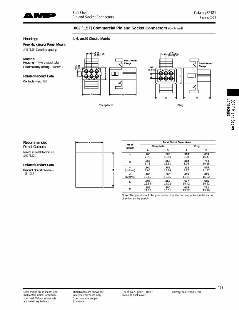
Soft ShellPin and Socket Connectors
Catalog 82181Revised 2-03
125
.062 [1.57] Commercial Pin and Socket Connectors (Continued)
Dimensions are in inches and Dimensions are shown for Technical Support – Refer www.tycoelectronics.commillimeters unless otherwise reference purposes only. to inside back cover.specified. Values in brackets Specifications subjectare metric equivalents. to change.
Recommended Panel CutoutsMaximum panel thickness is .060 [1.52].
Related Product DataProduct Specification —108-1037
Receptacle Plug
Panel Cutout DimensionsNo. of Receptacle Plug
CircuitsA B A B
.265 .505 .318 .6092 6.73 12.83 8.08 15.47
.265 .650 .318 .7543 6.73 16.51 8.08 19.154 .260 .785 .312 .865
(In-Line) 6.60 19.94 7.92 21.974 .400 .506 .465 .615
(Matrix) 10.16 12.85 11.81 15.62.505 .552 .607 .6156 12.83 14.02 15.42 15.62.552 .650 .615 .7529 14.02 16.51 15.62 19.10
Note: The panel should be punched so that the housing enters in the samedirection as the punch.
HousingsFree Hanging or Panel Mount.145 [3.68] Centerline spacing
MaterialHousing— Nylon, natural colorFlammability Rating — UL94V-2
Related Product DataContacts — pg. 123
4, 6, and 9 Circuit, Matrix
Dimensions are in inches and Dimensions are shown for Technical Support – Refer www.tycoelectronics.commillimeters unless otherwise reference purposes only. to inside back cover.specified. Values in brackets Specifications subjectare metric equivalents. to change.
Soft ShellPin and Socket Connectors
Catalog 82181Revised 2-03
126
Technical Documents
Related Product DataConnectorsUniversal MATE-N-LOK II — pg. 4-17Universal MATE-N-LOK — pg. 18-32Commercial MATE-N-LOK — pg. 33-47.156 MATE-N-LOK — pg. 48, 49.140 MATE-N-LOK — pg. 50-52.093 [2.36] Commercial
Pin and Socket — pg. 53-59Micro MATE-N-LOK 3 mm — pg. 60-89Mini-Universal MATE-N-LOK 2 —
pg. 90-99Mini-Universal MATE-N-LOK —
pg. 100-111(MR) Miniature Rectangular —
pg. 112-121.062 [1.57] Commercial
Pin and Socket — pg. 122-126
Various technical documents are available for your use:
Product Specifications describe technical performance characteristics and verification tests.They are intended for the Design, Component and Quality Engineer.108-1090 Universal MATE-N-LOK II Connector108-1031 Universal MATE-N-LOK Connector108-1053 Universal MATE-N-LOK Printed Circuit Board Header108-1031-1 Splash Proof Seal, Universal MATE-N-LOK108-1000 Commercial MATE-N-LOK Connector108-1077 Commercial MATE-N-LOK Printed Circuit Board Header108-49000 Commercial MATE-N-LOK IDC Insulation Displacement Connector108-8002 .156 Diameter MATE-N-LOK Connector108-1032 .140 Diameter MATE-N-LOK Pin and Socket Connector108-1038 .093 Commercial Pin and Socket Connectors108-1693 Mini-Universal MATE-N-LOK 2 Connectors108-1694 Mini-Universal MATE-N-LOK 2 Headers108-1542 Mini-Universal MATE-N-LOK Connectors108-1542-2 Splash Proof Seals for Mini-Universal MATE-N-LOK Connectors108-1543 Mini-Universal MATE-N-LOK Headers108-1836 Micro MATE-N-LOK 3 mm Pitch Soft Shell Connectors108-5151 Mini-Universal MATE-N-LOK Connector (UL 94V-2)108-5138 Mini-Universal MATE-N-LOK Connector (UL 94V-0)108-1022 (MR) Miniature Rectangular Connector108-1078 (MR) Miniature Rectangular Printed Circuit Board Header108-1037 .062 Commercial Pin and Socket Connectors
Application Specifications describe requirements for using the product in its intended appli-cation and/or crimping information. They are intended for the Packaging and DesignEngineer and the Machine Setup Person.114-1043 Universal MATE-N-LOK II Connectors (housings, contacts and strain reliefs)114-1010 Universal MATE-N-LOK Contact114-1012 Commercial MATE-N-LOK Contact114-49001 Commercial MATE-N-LOK IDC Insulation Displacement Connector114-1109 .156 Diameter MATE-N-LOK Connectors114-1007 .140 Diameter MATE-N-LOK Contact114-49000 .093 Commercial Pin and Socket Connectors114-1111 Mini-Universal MATE-N-LOK 2 Connectors114-13000 Micro MATE-N-LOK Connectors114-13089 Splash Proof Mini-Universal MATE-N-LOK Connectors114-16017 Mini-Universal MATE-N-LOK Connectors114-1014 (MR) Miniature Rectangular Contact114-1013 .062 Commercial Pin and Socket Connectors
Instruction Sheets provide instructions for assembling or applying the product. They are in-tended for the Manufacturing Assembler or Operator.
Universal MATE-N-LOK II Connectors: 408-3200 Housing, Contacts and Accessories
Universal MATE-N-LOK Connectors: 408-7714 Plug, Cap Header, Pin Socket Accessories 408-3320408-3392 Universal MATE-N-LOK Splash Proof Seals
Commercial MATE-N-LOK Connectors:408-3186 IDC Insulation Displacement Connector408-7166 Panel Mount Connector408-7200 Free-Hanging Connector408-7201 Detent Engagement Connectors -2 and 3 circuit408-7209 Commoning Tabs408-7215 Single Circuit Connector
Mini-Universal MATE-N-LOK 2 Connectors: 408-3393 Mini-Universal MATE-N-LOK 2 Connectors
Mini-Universal MATE-N-LOK Connectors: 408-3234 Mini-Universal MATE-N-LOK Connectors
(MR) Miniature Rectangular Connectors: 4 0 8 - 3 2 3 1 Pin Housing, Socket Housing, Contacts, andA c c e s s o r i e s

Dimensions are in inches and Dimensions are shown for Technical Support – Refer www.tycoelectronics.commillimeters unless otherwise reference purposes only. to inside back cover.specified. Values in brackets Specifications subjectare metric equivalents. to change.
Soft ShellPin and Socket Connectors
Catalog 82181Revised 2-03
127
Application Tooling
Semiautomatic bench crimpingmachines that also strip thewire, and therefore used for ter-minating jacketed cable.Feature manual precision ad-justment of crimp height, keyedstrip blades for faster, more ac-curate setups, and an efficientscrap removal system. All ad-justments can be made fromthe front of the machines with-out special tools. Available withcrimp quality monitoring.
SpecificationsWidth — 14 [355]Depth — 18 [457]Height — 33 [838] without reelWeight — 150 lb [68 kg]Electrical — 120 VAC, 50 or 60 Hz, .5 AAir — 80-100 psi [5.52-6.90 bar], 3.5scfm [0.00165 m3/s]Wire Range — 32-14 AWG [0.03-2 mm2]For more information, request Catalog65004.
AMP-O-LECTRIC Model “G”Terminating Machines,354500-1, -9, -11
AMP-O-MATIC Stripper-Crimper Machine,854040-3, -4
Semiautomatic Machines
Semiautomatic bench machinesfor crimping reeled terminalsand contacts, featuring a quietand reliable direct motor drive,microprocessor controls forease of setup and operation,and guarding and lighting designed for operator conve-nience and safety. All modelsare equipped with either manual or automatic precisionadjustment of crimp height.Machine-mounted sensors areavailable for crimp quality monitoring using conventionalminiature-style applicators.
SpecificationsWidth — 18.7-25.3 [475-643] depend-ing on applicator typeDepth — 21.5-28.1 [546-713] depend-ing on applicator typeHeight — 20 [508] Weight — 240 lb [110 kg]Electrical — 120 or 220 VAC, 50 or 60 HzAir — 90-110 psi [6.21-7.59 bar], 6 scfm [0.00282 m3/s] when requiredwith air-feed applicatorsWire Range — 26-10 AWG [0.12-6mm2] solid or stranded, depending onproduct appliedFor more information, request Catalog65828, Catalog 82275 [CrimpQuality Monitor (CQM)].
Crimp Quality Monitor
This system measures thecrimp height of each termina-tion as it is made. It also evalu-ates the quality of each crimp.If a crimp is questionable, themonitor alerts the operator withboth visual and audible alarms.It also features ports for printingand networking. For use withAMP-O-LECTRIC Model “G”and AMP-O-MATIC Stripper-
Crimper Machines, the monitoris mounted to the machine. Foruse with AMPOMATOR CLS I V +Machines, it is integrated intothe machine’s operating system,with the displays appearing onthe machine’s touch screen.
For more information, request Catalog82275.
N o t e : This listing is for reference purposes only. To obtain part numbers for specific applications call Technical Support.
Semiautomatic BenchTerminator for side- and end-feed reeled terminals and contacts. The ELT uses aDC motor with gear box drive.The result is a small-footprintdesign that is fast and quiet.Cycle time is less than 0.400sec. with an operation soundlevel of 76 dBa. With a crimpforce capacity of 3,000 pounds,the ELT is available for all butthe highest crimp force appli-cations. Optional equipment isalso available to meet your spe-cific application requirements.
For more information, request catalog1308382.
Entry Level Terminator (ELT),1338600-(x)
The combination of the StrippingModule with the AMP-O-LECTRICModel G Terminator or the EntryLevel Terminator provides aneconomical, proficient methodof stripping wire and crimping terminals on the same machine.Wires are stripped moments be-fore crimping, meaning there isvirtually no chance of damagingwire conductors during handlingor storage. Once the wire is fedinto the start sensor theStripping Module does the rest,improving placement accuracy.
For more information, request catalog1309085.
Optional Stripping Module (for the ELT and AMP-O-LECTRIC Model G Terminator)

Dimensions are in inches and Dimensions are shown for Technical Support – Refer www.tycoelectronics.commillimeters unless otherwise reference purposes only. to inside back cover.specified. Values in brackets Specifications subjectare metric equivalents. to change.
Soft ShellPin and Socket Connectors
Catalog 82181Revised 2-03
128
Application Tooling (Continued)
Automatic Machines
Fully-automatic machines that measure, cut, strip and terminate single leads.Microprocessor-controlled, andprogrammed and operatedusing an easy-to-follow, menu-driven touchscreen. Featuresinclude direct-drive terminatingunits with precision crimp heightadjustment, fully programmablesetups, wire runout and splicedetection, and motorized pre-feed with wire straightener.Crimp quality monitoring is also available.
SpecificationsWidth—159 [4 039] Depth—68 [1 730]Height—90 [2 285] min., with 24 [610] dia. reelWeight—2 000 lb [907 kg]Electrical—220 VAC, 50 or 60 Hz, 1 ∅, 20 A with neutral and groundAir—90 psi [6.21 bar], 15 scfm[0.00708 m3/s] sustainedWire Range—26-10 AWG[0.12-6 mm2] stranded, 26-16 AWG[0.12-1.4 mm2] solidLead Lengths — 3-90 [76.2-2 286],90-1 000 [2 286-25 400] with long leadconveyorsFor more information, request Catalog124324.
AMPOMATOR CLS IV+Lead-Making Machines,356500-1, -2

Dimensions are in inches and Dimensions are shown for Technical Support – Refer www.tycoelectronics.commillimeters unless otherwise reference purposes only. to inside back cover.specified. Values in brackets Specifications subjectare metric equivalents. to change.
Soft ShellPin and Socket Connectors
Catalog 82181Revised 2-03
129
Application Tooling (Continued)
Applicator Styles
Applicator and Hand ToolSelection Guide
Related Product DataContactsUniversal MATE-N-LOK II — pg. 7Universal MATE-N-LOK — pg. 21and 22Commercial MATE-N-LOK — pg. 37and 38.156 MATE-N-LOK — pg. 48.140 MATE-N-LOK — pg. 51.093 [2.36] Commercial Pin and Socket Connectors — pg. 55Mini-Universal MATE-N-LOK 2 — pg. 91Mini-Universal MATE-N-LOK — pg. 103(MR) Miniature Rectangular — pg. 115.062 [1.57] Commercial Pin and Socket Connectors — pg. 124
Stripper-Crimper (SCA)Applicators
End- and Side-Feed Heavy-Duty Miniature (HDM)Applicators
Crimp Quality Monitor (CQM) Applicators
■ For use with AMP-O-MATICStripper-Crimper Machines
■ Terminate a wide variety ofopen-barrel products
■ Quickly interchangeable torun different products
■ Easily repaired■ Simple dial-in settings to
handle similar products andvarious wire sizes
■ CQM applicators are available
■ Handle a wide variety ofproducts
■ Used with both semi- andfully-automatic machines
■ Quickly interchangeable torun different products
■ Easily repaired■ Simple dial-in settings to
handle similar products and various wire sizes
■ Same basic features as regular HDM and SCA applicators
■ Recommended for use with machines featuringmanual or automatic precision-adjust
■ Use two built-in sensors toprovide the Crimp QualityMonitor with data to measure crimp height, and evaluate the quality of each crimp
Applicators Hand ToolsProduct Line
A B C D EUniversal MATE-N-LOK II X X X X XUniversal MATE-N-LOK X X X X XCommercial MATE-N-LOK X X X X X.156 MATE-N-LOK X — — X —.140 MATE-N-LOK X X X X —.093 [2.36] Commercial
Pin and Socket Connectors X X X — X
Micro MATE-N-LOK 3mm X X X X —Sealed Mini-Universal
MATE-N-LOK X X X X —
Mini-Universal MATE-N-LOK 2 X X X X XMini-Universal MATE-N-LOK X X X X X(MR) Miniature Rectangular X X X X —.062 [1.57] Commercial
Pin and Socket Connectors X X X — X
A– Heavy Duty Miniature Applicators (HDM)B– Stripper-Crimper Applicators (SCA)C– Crimp Quality Monitor Applicators (CQM)D– CERTI-CRIMPHand ToolE– PRO-CRIMPERII Hand Tool
Note: This listing is for reference purposes only. To obtain part numbers for specific applications call Technical
Mechanical Hand Tools CERTI-CRIMP II Straight ActionHand Tools (SAHT) 91501-1,91502-1
Premium grade hand tools.Feature ratchet control toprovide complete crimpcycle. Die sets close in astraight line. Include a con-tact locator and wire stop,plus an insulation crimp
adjustment lever, whenapplicable. Approximateweight 1.3 lb [0.59 kg]For more information, request Catalog 65780.

Appl
icat
ion
Tool
ing
Soft ShellPin and Socket Connectors
Catalog 82181Revised 2-03
130
Application Tooling (Continued)
Dimensions are in inches and Dimensions are shown for Technical Support – Refer www.tycoelectronics.commillimeters unless otherwise reference purposes only. to inside back cover.specified. Values in brackets Specifications subjectare metric equivalents. to change.
Hand Tools
Related Product DataContactsUniversal MATE-N-LOK II — pg. 7Universal MATE-N-LOK — pg. 21and 22Commercial MATE-N-LOK — pg. 37and 38.156 MATE-N-LOK — pg. 48.140 MATE-N-LOK — pg. 51.093 [2.36] Commercial Pin and Socket Connectors — pg. 55Mini-Universal MATE-N-LOK 2 — pg. 91Mini-Universal MATE-N-LOK — pg. 103(MR) Miniature Rectangular — pg. 115.062 [1.57] Commercial Pin and Socket Connectors — pg. 124
Features CERTI-CRIMP Hand Tool PRO-CRIMPER II Hand ToolField Repair/Prototyping X XOEM Applications/Low Volume Production X —Ratchet Control X XBrush/Bellmouth Control X XPrecision Crimp Height Control X XLittle/No Operator Training X —Insulation Adjustment X —Repairable X —
CERTI-CRIMP II Hand Tool PRO-CRIMPER II Hand Tool
Catalog 65780 Catalog 82276
Product CERTI-CRIMP Hand Tool PRO-CRIMPER II Hand ToolLine Part Number Instruction Sheet Part Number Instruction Sheet
58439-1 408-9591 — —
Universal91510-1 408-8547 90548-1 408-9885
MATE-N-LOK II91500-1 408-8547 90546-1 408-9883
and91508-1 408-8547 90547-1 408-9884
Universal 91506-1 408-8547 90547-1 408-9884
MATE-N-LOK 69710-11 408-2095 — —58380-12 408-9433 — —58380-22 408-9433 — —
Commercial91515-1 408-8547 — —
MATE-N-LOK91512-1 408-8547 90574-1 408-988691504-1 408-8547 90575-1 408-9887
.156 MATE-N-LOK58631-1 408-4341 — —58632-1 408-4340 — —91552-1 408-8547 — —69710-11 408-2095 — —
.140 MATE-N-LOK58373-12 408-9442 — —58374-12 408-9442 — —
.093 Commercial — — 90872-1 408-9967Pin & Socket 90871-1 408-9966
Micro MATE-N-LOK 3mm91501-1 408-8547 — —91502-1 408-8547 — —91529-1 408-8547 — —
Mini-Universal 91522-1 408-8547 — —MATE-N-LOK 2 91594-1 408-8547 — —
90717-2 408-4443 — —
Mini-Universal 91529-1 408-8547 90758-1 408-9938MATE-N-LOK 91522-1 408-8547 90759-1 408-9962
Sealed Mini-Universal 91594-1 408-8547 90760-1 408-9963MATE-N-LOK 90717-2 408-4443 — —
Miniature 91534-1 408-8547 58514-1 408-9973Rectangular (MR) 91526-1 408-8547 58514-1 408-9973
.062 Commercial — — 90870-1 408-9965Pin & Socket 90869-1 408-9964
1Hand tool requires die set.2Die set.Note: This listing is for reference purposes only. To obtain part numbers for specific applications call Technical
Support.
and
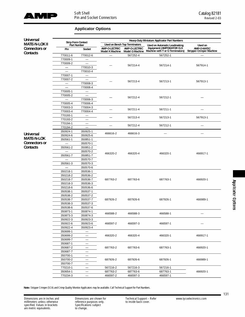
Soft ShellPin and Socket Connectors
Catalog 82181Revised 2-03
131Dimensions are in inches and Dimensions are shown for Technical Support – Refer www.tycoelectronics.commillimeters unless otherwise reference purposes only. to inside back cover.specified. Values in brackets Specifications subjectare metric equivalents. to change.
Applicator Options
Strip Form ContactHeavy-Duty Miniature Applicator Part Numbers
Part Number Used on Bench Top Terminators Used on Automatic Leadmaking Used on Pin Socket AMP-O-LECTRIC AMP-O-LECTRIC Equipment (AMPOMATOR CLS AMP-O-MATIC
Model K Machine Model G Machine Machine with T or G Terminators) Stripper-Crimper Machine
770011-6 770012-6 — 567252-4 567252-1 —770009-1 —770009-2 —
— 770010-3— 567214-4 567214-1 567914-1
— 770010-4770007-1 —770007-2 —
— 770008-3— 567213-4 567213-1 567913-1
— 770008-4770005-1 —770005-2 —
— 770006-3— 567212-4 567212-1 —
770005-4 770006-4770003-3 770004-3770003-4 770004-4
— 567211-4 567211-1 —
770193-1 —770193-2 —
— 567213-4 567213-1 567913-1
770194-1 —770194-2 —
— 567212-4 567212-1 —
350924-1 350925-1350924-6 350925-6
466616-2 466616-3 — —
350561-1 350851-1— 350570-1
350561-2 350851-2— 350570-2
350561-7 350851-7466320-2 466320-4 466320-1 466917-1
— 350570-7350561-3 350570-3
— 350570-6350218-1 350536-1350218-2 350536-2350218-7 350536-7 687763-2 687763-6 687763-1 466920-1350218-3 350536-3350218-6 350536-6350538-1 350537-1350538-2 350537-2350538-7 350537-7 687926-2 687926-6 687926-1 466989-1350538-3 350537-3350538-6 350537-6350873-1 350874-1350873-3 350874-3
466588-2 466588-3 466588-1 —
350922-3 350923-3350922-6 350923-6 466597-2 466597-3 466597-1 —350922-4 350923-4350699-1 —350699-2 — 466320-2 466320-4 466320-1 466917-1350699-7 —350687-1 —350687-2 — 687763-2 687763-6 687763-1 466920-1350687-7 —350700-1 —350700-2 — 687926-2 687926-6 687926-1 466989-1350700-7 —770210-1 — 567216-2 567216-3 567216-1350654-1 — 687763-2 687763-6 687763-1 466920-1770234-3 — 466597-2 466597-3 466597-1
Note: Stripper Crimper (SCA) and Crimp Quality Monitor Applicators may be available. Call Technical Support for Part Numbers.
UniversalMATE-N-LOK IIConnectors orContacts
UniversalMATE-N-LOKConnectors orContacts

Dimensions are in inches and Dimensions are shown for Technical Support – Refer www.tycoelectronics.commillimeters unless otherwise reference purposes only. to inside back cover.specified. Values in brackets Specifications subjectare metric equivalents. to change.
Soft ShellPin and Socket Connectors
Catalog 82181Revised 2-03
132
Applicator Options (Continued)
CommercialMATE-N-LOKConnectors orContacts
Strip Form ContactHeavy-Duty Miniature Applicator Part Numbers
Part Number Used on Bench Top Terminators Used on Automatic Leadmaking Used on Pin Socket AMP-O-LECTRIC AMP-O-LECTRIC Equipment (AMPOMATOR CLS AMP-O-MATIC
Model K Machine Model G Machine Machine with T or G Terminators) Stripper-Crimper Machine350079-1 350078-1350079-4 350078-4 466426-2 466426-3 466426-1 —350079-5 350078-561116-1 61314-161116-4 61314-461116-5 61314-5 466320-2 466320-4 466320-1 466917-161116-6 61314-661116-7 61314-761118-1 61117-161118-4 61117-461118-5 61117-5 687763-2 687763-6 687763-1 466920-161118-6 61117-661118-7 61117-7350558-1 350557-1350558-4 350557-4
687898-2 687898-4 687898-1 —
61527-2 — 466320-2 466320-4 466320-1 466917-1
61086-1 61085-1 466462-1 466462-3 466462-1 —61234-1 61233-1 687765-2 687765-2 — —
61627-1 61626-161627-2 61626-2
567306-2 567306-3 567306-1 —
350201-1 350200-1350201-2 350200-2
567309-2 567309-3 587309-1 —
350418-1 350417-1— 350417-3 466656-2 466656-3 466656-1 466922-1
350418-5 350417-5350416-1 350415-1350416-5 350415-5 466878-2 466878-3 466878-1 466959-1
— 350415-8770530-1 770529-1 567337-4 567337-6 567337-3 —770385-1 770383-1
— —567273-2 567273-4 567273-3 —
794608-1, -2, -3 — 1385194-2 1385194-3 1385194-1 —794609-1, -2, -3 — 1385377-2 1385377-3 1385377-1 —
— 794606-1, -2, -3 680893-2 680893-3 680893-1 —— 794607-1, -2, -3 680894-2 680894-3 680894-1 —
794216-1 794217-1794216-3 794217-3
567418-2 567418-3 567418-1 —
794218-1 794219-1794218-3 794219-3
567066-4 567066-5 567066-3 466990-2
794220-1 794221-1794220-3 794221-3
680854-2 680854-3 680854-1 466986-1
794222-1 794223-1794222-3 794223-3
650582-2 650582-2 — 567902-1
770835-1 770834-1770835-3 770834-3
567418-2 567418-3 567418-1 —
770901-1 770902-1770901-3 770902-3
567066-4 567066-5 567066-3 466990-2
770903-1 770904-1770903-3 770904-3
567067-2 567067-3 567067-1 466986-1
171636-1 171637-1— 171637-3
680582 567251-1 680582 567902-1
350968-1 794000-1350968-2 794000-2
466352-2 466352-3 466352-1 —
350967-1 641294-1350967-2 641294-2
466351-2 466351-4 466351-1 466913-1
350969-1 —350969-2 —
466351-2 466351-4 466351-1 466913-1
640391-1 640392-1640391-5 640392-5
466686-2 466686-3 466686-1 466955-1— 640392-2— 794046-1
350629-1 350628-1— 350628-2
350629-5 350628-5 687996-2 687996-3 687996-1 —— 350628-6— 794103-1
.140 MATE-N-LOKConnectors or Contacts
.156 MATE-N-LOK
.093 Pin andSocketConnectors or Contacts
Mini-Universal MATE-N-LOK 2Connectors or Contacts
Mini-UniversalMATE-N-LOKConnectors or Contacts
Micro-MATE-N-LOK 3mmConnector System
MiniatureRectangularConnectors or Contacts
.062 Pin andSocketConnectors or Contacts
Note: Stripper Crimper (SCA) and Crimp Quality Monitor Applicators may be available. Call Technical Support for Part Numbers.

Dimensions are in inches and Dimensions are shown for Technical Support – Refer www.tycoelectronics.commillimeters unless otherwise reference purposes only. to inside back cover.specified. Values in brackets Specifications subjectare metric equivalents. to change.
Soft ShellPin and Socket Connectors
Catalog 82181Revised 2-03
133
Part Number Index
350585 20, 29350586 20, 29350587 20, 29350588 20, 29350589 24350590 24350591 114350628 123, 132350629 123, 132350638 37350639 37350641 35, 44350642 35, 44350643 35, 44350644 35, 44350654 22, 28, 131350669 22, 28350687 22, 28, 131350689 21350690 21350699 22, 131350700 22, 131350705 22, 28350706 22350707 22350711 6, 12, 20, 29350712 6, 12, 20, 29350713 6, 12, 20, 29350714 6, 12, 20, 29350715 12, 13, 20, 23, 29, 30
350720 12, 13, 20, 23, 29, 30
350732 6, 12, 20, 29350735 12, 13, 20, 23, 29, 30
350736 12, 13, 20, 23, 29, 30
350737 6, 12, 20, 29350738 6, 12, 20, 29350742 6, 12, 20, 29350759 20, 30350760 20, 30350761 20, 30350762 20, 30350763 20, 30350764 20, 30350765 20, 30350766 12-15, 20, 23, 29-32350767 20, 23350777 12-15, 20, 23, 29-32350778 20, 23350779 12-15, 20, 23, 29-32350780 20, 23350781 20, 23350782 20, 23350783 20, 23350784 20, 23350786 6, 12, 20, 29350787 6, 12, 20, 29350789 6, 12, 20, 29350790 6, 12, 20, 29350792 6, 12, 20, 29350793 6, 12, 20, 29350809 1 2,1 3,1 5, 20,
23, 2 9, 3 0, 3 2
Part No. PageN o t e : This index lists all cataloged partsby base no. only. Complete part nos. (withprefixes and/or suffixes) are shown on thepage(s) indicated.
Italic indicates mating part nos.
60617 3760618 3760619 3760620 3760842 3760843 3761085 48,13261086 48,13261116 37,13261117 37,13261118 37,13261173 3761174 3761233 48, 13261234 48, 13261250 4861251 4861252 4861253 4861314 37, 13261320 3861518 3861527 38, 13261626 51, 13261627 51, 13284069 46171636 132171637 132171638 102171639 102172156 101, 103172157 101, 103172158 101, 103172159 101, 103172160 101, 103172161 101, 104172162 101, 104172163 101, 104172164 101, 103, 108
172165 94, 96, 101,103, 106, 108
172166 94, 96, 101,103, 106, 108
172167 94-96, 101,103, 106-108
172168 94-96, 101,103, 106-108
172169 94, 95, 101,104, 106, 107
172170 94, 95, 101,104, 106, 107
172171 94, 95, 101,104, 106, 107
172233 101, 103172234 101, 103172327 101, 103172328 101, 103172329 101, 103
Part No. Page
172330 101, 103172331 101, 103172332 101, 104172333 101, 104172334 101, 104172335 101, 103172336 101, 103172337 101, 103172338 101, 103172339 101, 103172340 101, 104172341 101, 104172342 101, 104172343 101, 103172344 101, 103172807 101, 105172808 101, 105172809 101, 105172958 101
172971 102173924 14, 31173925 14, 31173926 14, 31173956 101
173957 101, 105174552 36, 47174670 102174804 36, 47175332 46193796 16193797 16193839 16193841 16193842 16194002 17194009 17194010 17194012 17194013 17194014 17194017 17194018 17200821 38350020 118350021 118350022 118350073 38350074 38350078 37, 132350079 37, 132350200 51, 132350201 51, 132350209 35, 43350210 35, 43350211 36, 43, 45
350212 35, 43350213 35, 43350214 35, 43350218 21, 28, 131350219 35, 43350220 35, 43
Part No. Page350344 52350345 52350346 52350347 52350373 118350374 118350375 118350376 118350377 118350378 118350379 118350380 118350388 51350389 51350390 51350391 51350415 55, 132350416 55, 132350417 55, 132350418 55, 132350422 35, 43350423 35, 43350424 36, 43, 45
350425 35, 43350426 35, 43350427 35, 43350428 20, 29350429 20, 29350430 20, 29350431 20, 29350432 20, 29350433 20, 29350434 20, 29350444 37350522 118350523 118350524 118350536 21, 28, 131350537 21, 131350538 21, 131350539 35, 40, 43350540 35, 40, 43350541 35, 40, 43350542 35, 43350543 36, 40, 43350544 36, 40, 43350547 21, 28350550 21, 28350551 21350552 21350557 37, 132350558 37, 132350561 21, 131350570 21, 131350576 35, 44350577 35, 44350578 35, 44350579 35, 44350582 20, 29350583 20, 29350584 20, 29
Part No. Page

Dimensions are in inches and Dimensions are shown for Technical Support – Refer www.tycoelectronics.commillimeters unless otherwise reference purposes only. to inside back cover.specified. Values in brackets Specifications subjectare metric equivalents. to change.
Soft ShellPin and Socket Connectors
Catalog 82181Revised 2-03
134
Part Number Index (Continued)
350810 8, 20, 23350811 24350812 24350824 6, 13, 20, 30350825 6, 13, 20, 30350826 6, 13, 20, 30350827 6, 13, 20, 30350828 6, 13, 20, 30350829 6, 13, 20, 30350830 6, 13, 20, 30350831 6, 13, 20, 30350832 6, 13, 20, 30350833 6, 13, 20, 30350834 6, 13, 20, 30350835 6, 13, 20, 30350836 6, 13, 20, 30350837 6, 13, 20, 30350838 114350848 32350849 32350851 21, 131350865 20, 23350866 20, 23350867 20, 23350871 22350873 21, 131350874 21, 131350877 22350918 21350919 21350922 21, 131350923 21, 131350924 21, 131350925 21, 131350942 6, 15, 20, 32350943 6, 15, 20, 32350944 6, 15, 20, 32350945 6, 15, 20, 32350948 20, 32350949 20, 32350967 114, 132350968 114, 132350969 114, 132350986 20, 30350987 20, 30350988 20, 30350989 20, 30350990 20, 30350991 20, 30350992 20, 30380935 118380936 118380937 118380991 35, 43380999 35, 43480270 35, 40, 42, 43
480271 35, 42480273 35, 41480274 35, 41480275 35, 41480276 35, 41, 44
Part No. Page480277 35, 41, 44
480278 35, 41, 44
480283 35, 40, 42, 43
480284 35, 42480285 35, 40, 42, 43
480286 35, 42480287 35, 42, 43
480288 35, 42480303 35, 39, 43, 45
480304 35, 41480305 35, 39, 41480318 35, 39, 43, 45
480319 35, 39480323 35, 41480324 35, 41, 44
480339 35, 40480340 35, 40480345 35, 40480349 35, 39480350 35, 39480351 35, 39480387 35, 39480388 35, 39480393 35, 39480400 35, 39480401 35, 39480424 36, 39, 43, 45-47
480425 36, 41480426 36, 39, 41, 44, 45
480438 35, 42, 43
480439 35, 42480498 35, 39480510 51480512 51480585 51480586 51480594 118480634 118480672 52480673 52480698 20, 23, 29-31
480699 20, 23480700 20, 23, 29-31
480701 20, 23480702 20, 23, 29-32
480703 20, 23480704 20, 23, 29, 30
480705 20, 23480706 20, 23, 29, 30
480707 20, 23480708 20, 23, 29, 30
480709 20, 23480710 20, 23, 29, 30
480711 20, 23480720 35, 40, 43
480721 35, 40, 43
480722 40, 43
480763 20, 23, 29, 30, 32
480764 20, 23480772 36640309 21
Part No. Page640310 21640347 21640391 123, 132640392 123, 132640415 24640466 20, 29640467 20, 30640497 113, 120640498 113, 120640499 113, 120640500 113, 120640501 113, 120640502 113, 120640503 113, 120640504 113, 120640505 113, 120640506 113, 120640507 113, 115640508 113, 115640509 113, 115640510 113, 115640511 113, 116640512 113, 116640513 113, 116640514 113, 116640515 113, 116640516 113, 116640517 113, 115, 120
640518 113, 115, 120
640519 113, 115, 120
640520 113, 115, 120
640521 113, 116, 120
640522 113, 116, 120
640523 113, 116, 120
640524 113, 116, 120
640525 113, 116, 120
640526 113, 116, 120
640545 114640579 114640580 114640581 20, 23, 29, 30, 32
640582 20, 23, 29, 32
640583 20, 32640584 20, 32640585 20, 23, 29, 32
640586 20, 23, 29, 32
640587 20, 32640713 11, 25640714 11, 25640715 11, 25640716 11, 25640717 11, 25640718 11, 25640719 25640720 25640721 25640722 25640723 25640724 25640900 6, 8, 12, 20, 29640901 6, 8, 13, 20, 30
Part No. Page641083 20
641084 20641294 114, 132641300 114641737 36, 45
641763 25641764 20
641765 20
641766 20
641767 20
641768 20641769 20641770 20641771 20641775 25641776 11, 25641777 25641778 25641825 20, 29641828 20, 29641831 20, 29641832 20, 29641945 11, 25641963 20, 29641964 6, 12, 20, 29641965 20, 29641966 6, 12, 20, 29641967 20, 29641968 6, 12, 20, 29641969 20, 29641970 6, 12, 20, 29641971 20, 29641972 6, 12, 20, 29641973 20, 29641974 6, 12, 20, 29641975 20, 29641976 6, 12, 20, 29643030 11, 25643182 25643226 6, 15, 20, 32643228 6, 15, 20, 32643230 6, 15, 20, 32643232 6, 15, 20, 32643234 20, 32643235 32643236 20, 32643237 32643313 25643314 25643405 20, 29643406 6, 12, 20, 29643407 20, 29643408 20, 29643410 20, 29643411 20, 30643412 6, 13, 20, 30643413 20, 30643414 6, 13, 20, 30643415 20, 30643416 6, 13, 20, 30643423 20, 30
Part No. Page
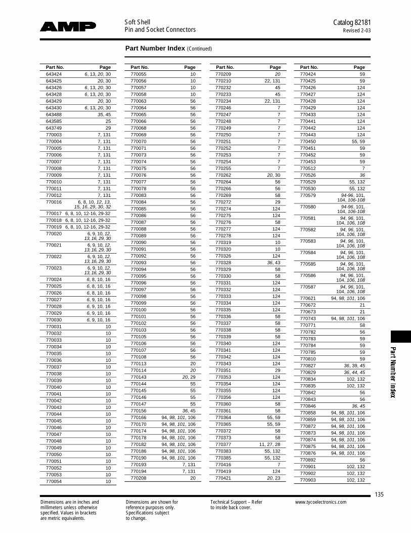
Dimensions are in inches and Dimensions are shown for Technical Support – Refer www.tycoelectronics.commillimeters unless otherwise reference purposes only. to inside back cover.specified. Values in brackets Specifications subjectare metric equivalents. to change.
Soft ShellPin and Socket Connectors
Catalog 82181Revised 2-03
135
Part Number Index (Continued)
770055 10770056 10770057 10770058 10770063 56770064 56770065 56770066 56770068 56770069 56770070 56770071 56770073 56770074 56770075 56770076 56770077 56770078 56770083 56770084 56770085 56770086 56770087 56770088 56770089 56770090 56770091 56770092 56770093 56770094 56770095 56770096 56770097 56770098 56770099 56770100 56770101 56770102 56770103 56770105 56770106 56770107 56770108 56770113 20770114 20
770143 20, 29770144 55770145 55770146 55770147 55770156 36, 45770166 94, 98, 101, 106770170 94, 98, 101, 106770174 94, 98, 101, 106770178 94, 98, 101, 106770182 94, 98, 101, 106770186 94, 98, 101, 106770190 94, 98, 101, 106770193 7, 131770194 7, 131770208 20
770209 20
770210 22, 131770232 45770233 45770234 22, 131770246 7770247 7770248 7770249 7770250 7770251 7770252 7770253 7770254 7770255 7770262 20, 30770264 56770266 56770269 58770272 29770274 124770275 124770276 58770277 124770278 124770319 10770320 10770326 124770328 36, 43770329 58770330 58770331 124770332 124770333 124770334 124770335 124770336 58770337 58770338 58770339 58770340 124770341 124770342 124770343 124770351 29770353 124770354 124770355 124770356 124770360 58770361 58770364 55, 59770365 55, 59770372 58770373 58770377 11, 27, 28770383 55, 132770385 55, 132770416 7770419 124770421 20, 23
770424 59770425 59770426 124770427 124770428 124770429 124770433 124770441 124770442 124770443 124770450 55, 59770451 59770452 59770453 59770512 7770526 36
770529 55, 132770530 55, 132770579 94-96, 101,
104, 106-108
770580 94-96, 101, 104, 106-108
770581 94, 96, 101, 104, 106, 108
770582 94, 96, 101, 104, 106, 108
770583 94, 96, 101, 104, 106, 108
770584 94, 96, 101, 104, 106, 108
770585 94, 96, 101, 104, 106, 108
770586 94, 96, 101, 104, 106, 108
770587 94, 96, 101, 104, 106, 108
770621 94, 98, 101, 106770672 21770673 21770743 94, 98, 101, 106770771 58770782 56770783 59770784 59770785 59770810 59770827 36, 39, 45
770829 36, 44, 45
770834 102, 132770835 102, 132770842 56770843 56770846 36, 45
770858 94, 98, 101, 106770859 94, 98, 101, 106770872 94, 98, 101, 106770873 94, 98, 101, 106770874 94, 98, 101, 106770875 94, 98, 101, 106770876 94, 98, 101, 106770892 56770901 102, 132770902 102, 132770903 102, 132
Part No. Page Part No. Page Part No. Page643424 6, 13, 20, 30643425 20, 30643426 6, 13, 20, 30643428 6, 13, 20, 30643429 20, 30643430 6, 13, 20, 30643488 35, 45643585 25643749 29770003 7, 131770004 7, 131770005 7, 131770006 7, 131770007 7, 131770008 7, 131770009 7, 131770010 7, 131770011 7, 131770012 7, 131770016 6, 8, 10, 12, 13,
15, 16, 29, 30, 32
770017 6, 8, 10, 12-16, 29-32770018 6, 8, 10, 12-16, 29-32770019 6, 8, 10, 12-16, 29-32770020 6, 9, 10, 1 2,
1 3, 1 6, 2 9, 3 0
770021 6, 9, 10, 1 2, 1 3, 1 6, 2 9, 3 0
770022 6, 9, 10, 1 2, 1 3, 1 6, 2 9, 3 0
770023 6, 9, 10, 1 2, 1 3, 1 6, 2 9, 3 0
770024 6, 8, 10, 16770025 6, 8, 10, 16770026 6, 8, 10, 16770027 6, 9, 10, 16770028 6, 9, 10, 16770029 6, 9, 10, 16770030 6, 9, 10, 16770031 10770032 10770033 10770034 10770035 10770036 10770037 10770038 10770039 10770040 10770041 10770042 10770043 10770044 10770045 10770046 10770047 10770048 10770049 10770050 10770051 10770052 10770053 10770054 10
Part No. Page

Dimensions are in inches and Dimensions are shown for Technical Support – Refer www.tycoelectronics.commillimeters unless otherwise reference purposes only. to inside back cover.specified. Values in brackets Specifications subjectare metric equivalents. to change.
Soft ShellPin and Socket Connectors
Catalog 82181Revised 2-03
136
Part Number Index (Continued)
794432 95, 107794606 62-65, 132794607 62-65, 132794608 62, 65, 132794609 62, 65, 132794610 62-65794611 62-65794612 62, 65794613 62, 65794615 62, 71794616 62, 70794617 62, 64, 67, 76-79,
85-89
794618 64, 86794619 64, 86794620 64, 86794621 64, 88794622 64, 88794623 64, 88794624 64, 87794625 64, 87794626 64, 87794627 64, 89794628 64, 89794629 64, 89794630 64, 76794631 64, 76794632 64, 76794633 64, 78794634 64, 78794635 64, 78794636 64, 79794637 64, 79794638 64, 79794677 64, 85794678 64, 85794679 64, 85794680 64, 77794681 64, 77794682 64, 77794683 52794699 52794700 51794714 26794715 26794716 26794758 102794760 26794761 26794762 26794772 103, 104794781 101, 104, 106, 108
794805 101, 103, 106, 108
794821 101, 104, 106, 108
794894 101, 103, 106, 108
794895 101, 103, 106, 108
794896 101, 103794939 101, 103794940 101, 103794941 101, 104794942 101, 104
794239 92, 98794240 92, 98
794241 92, 98794242 92, 98
794243 92, 98794244 92, 98
794245 93, 98794246 93, 98
794247 93, 98794248 93, 98
794249 93, 98794250 93, 98
794251 93, 98794252 93, 98
794253 93, 98794254 93, 98
794255 93, 98794256 93, 98
794257 93, 98794258 93, 98
794259 93, 98794260 93, 98
794261 93, 98794262 93, 98
794263 93, 98794264 93, 98
794265 93794266 93794267 93, 98794268 93, 98
794269 27794270 27794271 27794272 27794273 27794274 27794275 27794276 27794277 27794278 27794279 27794280 27794281 27794282 27794285 44794287 36, 44794325 95, 98, 101, 107794326 95, 98, 101, 107794327 95, 98, 101, 107794328 95, 98, 101, 107794329 95, 98, 101, 107794330 95, 98, 101, 107794369 92794370 110794374 101, 108794380 123794406 102794407 102794412 49794413 49794423 110
794185 92, 98
794186 92, 94, 96, 98, 106, 108
794187 92, 98
794188 92, 94-96, 98, 106-108
794189 92, 98
794190 92, 94-96, 98,106-108
794191 91, 98
794192 93, 94-96, 98,106-108
794193 93, 98
794194 93, 94, 95, 98,106, 107
794195 93, 98
794196 93, 94-96, 98,106-108
794197 93, 98
794198 93, 94, 96, 98,106, 108
794199 93, 98
794200 93, 94, 95, 98,106, 107
794201 93, 98
794202 93, 94, 96, 98,106, 108
794203 93, 98
794204 93, 94, 95, 98,106, 107
794205 93, 98
794206 93, 94, 96, 98,106, 108
794207 93, 98
794208 93, 94, 96, 98,106, 108
794209 93, 98
794210 93, 94, 96, 98,106, 108
794211 93, 98
794212 93, 94, 96, 98,106, 108
794213 93, 98
794214 93, 94, 96, 98,106, 108
794215 93, 98
794216 91, 132794217 91, 132794218 91, 132794219 91, 132794220 91, 132794221 91, 132794222 91, 132794223 91, 132794224 91794225 91794226 91794227 91794228 91794229 91794230 91794231 91794236 43794237 92, 98794238 92, 98
770904 102, 132770966 96, 98, 101, 108770967 96, 98, 101, 108770968 96, 98, 101, 108770969 96, 98, 101, 108770970 96, 98, 101, 108770971 96, 98, 101, 108770972 96, 98, 101, 108770973 96, 98, 101, 108770974 96, 98, 101, 108770983 123770985 102770986 102770987 102770988 102770994 32770997 36, 44794000 114, 132794001 114794012 35, 40
794015 56794016 123794017 123794018 123794019 123794036 36, 45794040 94, 98, 101, 106794044 101
794046 123, 132794058 102794059 102794061 52794065 94, 98, 101, 106794066 94, 98, 101, 106794067 94, 98, 101, 106794068 94, 98, 101, 106794069 94, 98, 101, 106794070 94, 98, 101, 106794071 94, 98, 101, 106794072 94, 98, 101, 106794073 94, 98, 101, 106794074 94, 98, 101, 106794075 94, 98, 101, 106794076 94, 98, 101, 106794077 94, 98, 101, 106794078 94, 98, 101, 106794079 94, 98, 101, 106794096 20, 23794103 123, 132794105 96, 98, 101, 108794106 96, 98, 101, 108794107 96, 98, 101, 108794108 96, 98, 101, 108794116 49794117 49794118 49794120 35, 45794130 98, 101
794132 36, 39794184 92, 94, 96, 98,
106, 108
Part No. Page Part No. Page Part No. Page Part No. Page

Dimensions are in inches and Dimensions are shown for Technical Support – Refer www.tycoelectronics.commillimeters unless otherwise reference purposes only. to inside back cover.specified. Values in brackets Specifications subjectare metric equivalents. to change.
Soft ShellPin and Socket Connectors
Catalog 82181Revised 2-03
137
Part Number Index (Continued)
1445093 63, 721445094 63, 731445095 63, 741445096 63, 751445097 63, 801445098 63, 811445099 63, 821445100 63, 831445101 63, 84
1445084 63, 721445085 63, 731445086 63, 741445087 63, 751445088 63, 801445089 63, 811445090 63, 821445091 63, 831445092 63, 84
1445050 63, 721445051 63, 731445052 63, 741445053 63, 751445054 63, 801445055 63, 811445056 63, 821445057 63, 831445058 63, 84
794995 103, 104926302 20, 23926307 20, 23926308 20, 23926309 20, 231445022 62, 63, 66, 72-75,
80-84
1445032 751445048 62, 691445049 62, 68
Part No. Page Part No. Page Part No. Page Part No. Page
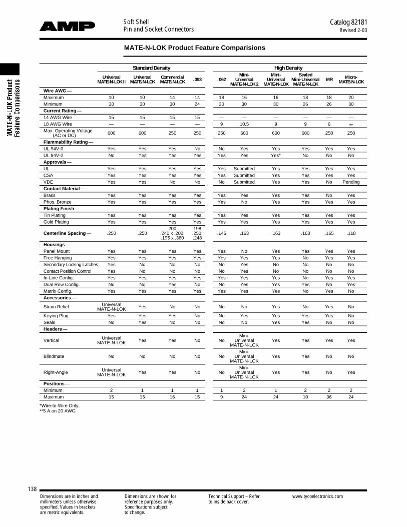
Dimensions are in inches and Dimensions are shown for Technical Support – Refer www.tycoelectronics.commillimeters unless otherwise reference purposes only. to inside back cover.specified. Values in brackets Specifications subjectare metric equivalents. to change.
Soft ShellPin and Socket Connectors
Catalog 82181Revised 2-03
138
MATE-N-LOK Product Feature Comparisions
Standard Density High Density
Universal Universal Commercial Mini- Mini- SealedMATE-N-LOK II MATE-N-LOK MATE-N-LOK .093 .062 Universal Universal Mini-Universal MR Micro-
MATE-N-LOK 2 MATE-N-LOK MATE-N-LOK MATE-N-LOK
Wire AWG —Maximum 10 10 14 14 18 16 16 18 18 20Minimum 30 30 30 24 30 30 30 26 26 30Current Rating—14 AWG Wire 15 15 15 15 — — — — — —18 AWG Wire — — — — 9 10.5 9 9 6 **Max. Operating Voltage 600 600 250 250 250 600 600 600 250 250(AC or DC)Flammability Rating —UL 94V-0 Yes Yes Yes No No Yes Yes Yes Yes YesUL 94V-2 No Yes Yes Yes Yes Yes Yes* No No NoApprovals —UL Yes Yes Yes Yes Yes Submitted Yes Yes Yes YesCSA Yes Yes Yes Yes Yes Submitted Yes Yes Yes YesVDE Yes Yes No No No Submitted Yes Yes No PendingContact Material —Brass Yes Yes Yes Yes Yes Yes Yes Yes No YesPhos. Bronze Yes Yes Yes Yes Yes No Yes Yes Yes YesPlating Finish —Tin Plating Yes Yes Yes Yes Yes Yes Yes Yes Yes YesGold Plating Yes Yes Yes Yes Yes Yes Yes Yes Yes Yes
.200; .198; Centerline Spacing — .250 .250 .240 x .202; .250; .145 .163 .163 .163 .165 .118
.195 x .360 .248Housings —Panel Mount Yes Yes Yes Yes Yes No Yes Yes Yes YesFree Hanging Yes Yes Yes Yes Yes Yes Yes No Yes YesSecondary Locking Latches Yes No No No No Yes No No No NoContact Position Control Yes No No No No Yes No No No NoIn-Line Config. Yes Yes Yes Yes Yes Yes Yes No Yes YesDual Row Config. No No Yes No No Yes Yes Yes No YesMatrix Config. Yes Yes Yes Yes Yes Yes Yes No Yes NoAccessories —
Strain Relief Universal Yes No No No No Yes No Yes NoMATE-N-LOKKeying Plug Yes Yes Yes No No Yes Yes Yes Yes NoSeals No Yes No No No No Yes Yes No NoHeaders —
Mini-Vertical Universal Yes Yes No No Universal Yes Yes Yes YesMATE-N-LOK MATE-N-LOK
Mini-Blindmate No No No No No Universal Yes Yes No No
MATE-N-LOKMini-
Right-Angle Universal Yes Yes No No Universal Yes Yes No YesMATE-N-LOK MATE-N-LOKPositions —Minimum 2 1 1 1 1 2 1 2 2 2Maximum 15 15 16 15 9 24 24 10 36 24
*Wire-to-Wire Only.**5 A on 20 AWG
13982181–10M–LUG–FP–2-03–0G3B Tyco Electronics CorporationPrinted in the U.S.A. www.tycoelectronics.com
Global Contacts
Americas
Asia/Pacific
Argentina – Buenos Aires Phone: +54-11-4733-2200 Fax: +54-11-4733-2250
Brasil – São PauloPhone: +55-11-3611-1311Fax: +55-11-3611-0397
Canada – MarkhamPhone: +905-475-6222Fax: +905-474-5520Product Information Center:(Technical Support)Phone: +905-470-4425Fax: +905-474-5525
Colombia – Bogota Phone: +57-1-240-9396 Fax: +57-1-660-0206
Mexico – Mexico CityPhone: +52-55-5-729-0425Fax: +52-55-5-398-1430
United States – Harrisburg, PA Phone: +717-564-0100 Fax: +717-986-7575Product Information Center:(Technical Support)Phone: +800-522-6752Fax: +717-986-7575
Australia – Sydney Phone: +61-2-9840-8200 Fax: +61-2-9899-5649Product Information Center:(Technical Support)Phone: +61-2-9554-2600Fax: +61-2-9502-2556
India – Bangalore Phone: +91-80-841-0200 Fax: +91-80-841-0210
Indonesia – Jakarta Phone: +6221-526-7852 Fax: +6221-526-7856
Japan – Kawasaki, KanagawaPhone: +81-44-844-8079Fax: +81-44-844-8733Product Information Center:(Technical Support)Phone: +81-44-844-8013Fax: +81-44-812-3200Raychem ProductsPhone: +81-44-900-5102Fax: +81-44-5025-5027
Korea – Seoul Phone: +82-2-3274-0535 Fax: +82-2-3274-0524/0531
Malaysia – Selangor Phone: +60-3-7053055 Fax: +60-3-7053066
New Zealand – Auckland Phone: +64-9-634-4580 Fax: +64-9-634-4586
Philippines – Makati City Phone: +632-867-8641 Fax: +632-867-8661
People’s Republic of ChinaHong Kong Phone: +852-2735-1628 Fax: +852-2735-0243
Shanghai Phone: +86-21-6485-0602 Fax: +86-21-6485-0728
Shunde Phone: +86-765-775-1368 Fax: +86-765-775-2823
Singapore – Singapore Phone: +65-482-0311 Fax: +65-482-1012Raychem ProductsPhone: +65-486-6151Fax: +65-654-5514
Taiwan – Taipei Phone: +886-2-2664-9977 Fax: +886-2-2664-9900
Thailand – Bangkok Phone: +66-2-955-0500Fax: +66-2-955-0505
Vietnam – Ho Chi Minh CityPhone: +84-8-8232-546/7Fax: +84-8-8221-443
For Latin/South American Countries not shownPhone: +57-1-240-9396Fax: +57-1-660-0206
Europe/Middle East/AfricaAustria – Vienna Phone: +43-190-560-0 Fax: +43-190-560-1333
Belgium – Kessel-Lo Phone: +32-16-352-300 Fax: +32-16-352-352
Bulgaria – Sofia Phone: +359-2-971-2152 Fax: +359-2-971-2153
Czech Republic – Kurim Phone: +420-5-41-162-111 Fax: +420-5-41-162-223
Denmark – Viby J Phone: +45-70-15-52-00 Fax: +45-86-29-51-33
Egypt – Cairo Phone: +20-2-417-76-47 Fax: +20-2-419-23-34
Estonia – Tallinn Phone: +372-65-05-474 Fax: +372-65-05-470
Finland – Helsinki Phone: +358-95-12-34-20 Fax: +358-95-12-34-250
France – Cergy-Pontoise Phone: +33-1-3420-8888 Fax: +33-1-3420-8600 Product Information Center:(Technical Support)Phone: +33-1-3420-8943 Fax: +33-1-3420-8623
France Tyco Electronics Export – St Ouen L’Aumone Phone: +33-1-3440-7200 Fax: +33-1-3440-7220 or
+33-1-3440-7230
Germany – Bensheim Phone: +49-6251-133-0 Fax: +49-6251-133-1600 Product Information Center:(Technical Support)Phone: +49-6251-133-1999 Fax: +49-6251-133-1988
Germany – Langen Phone: +49-6103-709-0 Fax: +49-6103-709-1223
Germany – Speyer Phone: +49-6232-30-0 Fax: +49-6232-30-2243
Germany HTS Division – Neunkirchen Phone: +49-2247-305-0 Fax: +49-2247-305-122
Great Britain – Stanmore Middlesex Phone: +44-181-954-2356 Fax: +44-181-954-6234 Product Information Center:(Technical Support)Freephone GB: 0800-267-666 Phone: +44-141 810 8967…69 Fax: +44-141 810 8971 Great Britain – Dorcan, Swindon Raychem ProductsPhone: +44-1793-528171Fax: +44-1793-572516
Greece – Athens Phone: +30-1-9370-396/397 Fax: +30-1-9370-655
Hungary – Budapest Phone: +36-1-289-1000 Fax: +36-1-289-1010
Ireland – Dublin Phone: +353-1-820-3000 Fax: +353-1-820-9790
Israel – Yokneam Phone: +972-4-959-0508 Fax: +972-4-959-0506
Italy – Collegno (Torino) Phone: +39-011-4012-111 Fax: +39-011-4031-116
Lithuania – Vilnius Phone: +370-5-21-31-402 Fax: +370-5-21-31-403
Netherlands – ’s-Hertogenbosch Phone: +31-73-6246-246 Fax: +31-73-6212-365 Product Information Center:(Technical Support)Phone: +31-73-6246-999 Fax: +31-73-6246-998
Norway – Nesbru Phone: +47-66-77-88-99 Fax: +47-66-77-88-55
Poland – Warsaw Phone: +48-22-5490-888 Fax: +48-22-5490-880
Romania – Bucharest Phone: +40-1-311-3479+3596 Fax: +40-1-312-0574
Russia – Moscow Phone: +7-095-926-55-06…09 Fax: +7-095-926-55-05
Russia – St. Petersburg Phone: +7-812-325-30-83 Fax: +7-812-325-32-88
Scotland – Dundee Madison Cable ProductsPhone: +44-1382-508080 Fax: +44-1382-505060
Slovakia – Banská Bystrica Phone: +421-48-415-20-11/12 Fax: +421-48-415-20-13
Slovenia – Ljubljana Phone: +386-1561-3270 Fax: +386-1561-3240
South Africa – Port Elizabeth Phone: +27-41-405-4500 Fax: +27-41-486-1314
Spain – Barcelona Phone: +34-93-291-0330 Fax: +34-93-201-7879 Product Information Center:(Technical Support): Phone: +34-93-291-0330 Fax: +34-93-200-3779
Sweden – Upplands Väsby Phone: +46-8-50-72-50-00 Fax: +46-8-50-72-50-01
Switzerland – Steinach Phone: +41-71-447-0447 Fax: +41-71-447-0444
Turkey – Istanbul Phone: +90-212-281-8181…3
+90-212-282-5130/5430 Fax: +90-212-281-8184
Ukraine – Kiev Phone: +38-044-238-6908 Fax: +38-044-568-5740

Catalog 82181Revised 2-03
Soft Shell Pin and Socket Connectors
Soft Shell Pin and Socket ConnectorsCatalog 82181 Revised 2-03
TYCO ELECTRONICS CORPORATION