two stage progressive gas burners - thermal … stage progressive gas burners ... this document...
TRANSCRIPT
Technical Data Leafl etTS0046UK06
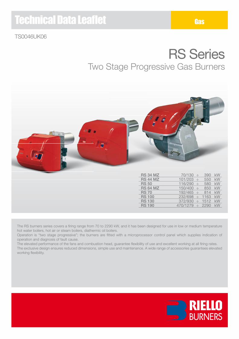
RS SeriesTwo Stage Progressive Gas Burners
The RS burners series covers a fi ring range from 70 to ��90 kW, and it has been designed for use in low or medium temperature hot water boilers, hot air or steam boilers, diathermic oil boilers.Operation is “two stage progressive”; the burners are fi tted with a microprocessor control panel which supplies indication of operation and diagnosis of fault cause.The elevated performance of the fans and combustion head, guarantee fl exibility of use and excellent working at all fi ring rates.The exclusive design ensures reduced dimensions, simple use and maintenance. A wide range of accessories guarantees elevated working fl exibility.
Gas
RS 34 MZ 70/130 ÷ 390 kWRS 44 MZ 101/203 ÷ 550 kWRS 50 116/290 ÷ 580 kWRS 64 MZ 150/400 ÷ 850 kWRS 70 192/465 ÷ 814 kWRS 100 232/698 ÷ 1163 kWRS 130 372/930 ÷ 1512 kWRS 190 470/1279 ÷ 2290 kW
�
RS Series
Technical Data
Since the Company is constantly engaged in the production improvement, the aesthetic and dimensional features, the technical data, the equipment and the accessories can be changed. This document contains confidential and proprietary information of RIELLO S.p.A. Unless authorised, this information shall not be divulged, nor duplicated in whole or in part.
Reference conditions:Temperature: �0°C - Pressure: 1013,5 mbar - Altitude: 0 m a.s.l. - Noise measured at a distance of 1 meter.
(01) Centrifugal with reverse curve blades(0�) Centrifugal with forward curve blades(03) 1/50/�30~(±10%)(04) 1/50-60/��0-�30~(±10%)(05) 3/50/�30-400~(±10%)(06) 3/50-60/��0-400~(±10%)
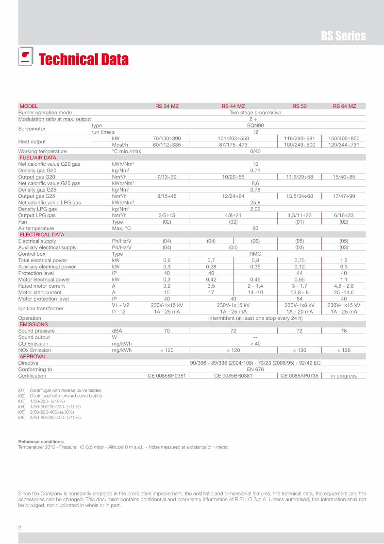
Model RS 34 MZ RS 44 MZ RS 50 RS 64 MZBurner operation mode Two stage progressiveModulation ratio at max. output 2 ÷ 1
Servomotortype SQN90run time s 12
Heat outputkW 70/130÷390 101/203÷550 116/290÷581 150/400÷850Mcal/h 60/112÷335 87/175÷473 100/249÷500 129/344÷731
Working temperature °C min./max. 0/40 Fuel/AiR dATANet calorific value G20 gas kWh/Nm3 10density gas G20 kg/Nm3 0,71output gas G20 Nm3/h 7/13÷39 10/20÷55 11,6/29÷58 15/40÷85Net calorific value G25 gas kWh/Nm3 8,6density gas G25 kg/Nm3 0,78output gas G25 Nm3/h 8/15÷45 12/24÷64 13,5/34÷68 17/47÷99Net calorific value lPG gas kWh/Nm3 25,8density lPG gas kg/Nm3 2,02output lPG gas Nm3/h 3/5÷15 4/8÷21 4,5/11÷23 6/16÷33Fan Type (02) (02) (01) (02)Air temperature Max. °C 60 eleCTRiCAl dATAelectrical supply Ph/Hz/V (04) (04) (06) (05) (05)Auxiliary electrical supply Ph/Hz/V (04) (04) (03) (03)Control box Type RMGTotal electrical power kW 0,6 0,7 0,8 0,75 1,2Auxiliary electrical power kW 0,3 0,28 0,35 0,12 0,3Protection level iP 40 40 44 40Motor electrical power kW 0,3 0,42 0,45 0,65 1,1Rated motor current A 3,2 3,5 2 - 1,4 3 - 1,7 4,8 - 2,8 Motor start current A 15 17 14 -10 13,8 - 8 25 -14,6Motor protection level iP 40 40 54 40
ignition transformerV1 - V2 230V-1x15 kV 230V-1x15 kV 230V-1x8 kV 230V-1x15 kVi1 - i2 1A - 25 mA 1A - 25 mA 1A - 20 mA 1A - 25 mA
operation intermittent (at least one stop every 24 h) eMiSSioNSSound pressure dBA 70 72 72 76Sound output W --Co emission mg/kWh < 40Nox emission mg/kWh < 120 < 120 < 130 < 120 APPRoVAldirective 90/396 - 89/336 (2004/108) - 73/23 (2006/95) - 92/42 eCConforming to eN 676Certification Ce 0085BR0381 Ce 0085BR0381 Ce 0085AP0735 in progress
3
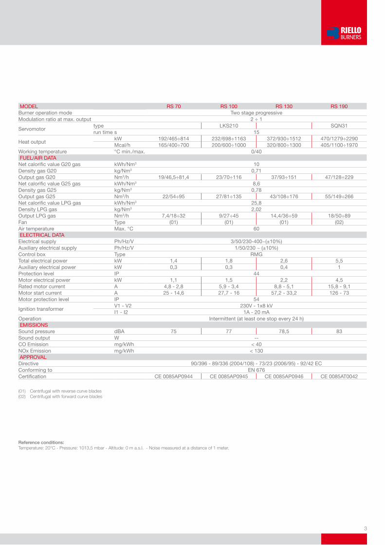
Model RS 70 RS 100 RS 130 RS 190Burner operation mode Two stage progressiveModulation ratio at max. output 2 ÷ 1
Servomotortype lKS210 SQN31run time s 15
Heat outputkW 192/465÷814 232/698÷1163 372/930÷1512 470/1279÷2290Mcal/h 165/400÷700 200/600÷1000 320/800÷1300 405/1100÷1970
Working temperature °C min./max. 0/40 Fuel/AiR dATANet calorific value G20 gas kWh/Nm3 10density gas G20 kg/Nm3 0,71output gas G20 Nm3/h 19/46,5÷81,4 23/70÷116 37/93÷151 47/128÷229Net calorific value G25 gas kWh/Nm3 8,6density gas G25 kg/Nm3 0,78output gas G25 Nm3/h 22/54÷95 27/81÷135 43/108÷176 55/149÷266Net calorific value lPG gas kWh/Nm3 25,8density lPG gas kg/Nm3 2,02output lPG gas Nm3/h 7,4/18÷32 9/27÷45 14,4/36÷59 18/50÷89Fan Type (01) (01) (01) (02)Air temperature Max. °C 60 eleCTRiCAl dATAelectrical supply Ph/Hz/V 3/50/230-400~(±10%)Auxiliary electrical supply Ph/Hz/V 1/50/230 ~ (±10%)Control box Type RMGTotal electrical power kW 1,4 1,8 2,6 5,5Auxiliary electrical power kW 0,3 0,3 0,4 1Protection level iP 44Motor electrical power kW 1,1 1,5 2,2 4,5Rated motor current A 4,8 - 2,8 5,9 - 3,4 8,8 - 5,1 15,8 - 9,1Motor start current A 25 - 14,6 27,7 - 16 57,2 - 33,2 126 - 73Motor protection level iP 54
ignition transformerV1 - V2 230V - 1x8 kVi1 - i2 1A - 20 mA
operation intermittent (at least one stop every 24 h) eMiSSioNSSound pressure dBA 75 77 78,5 83Sound output W --Co emission mg/kWh < 40Nox emission mg/kWh < 130 APPRoVAldirective 90/396 - 89/336 (2004/108) - 73/23 (2006/95) - 92/42 eCConforming to eN 676Certification Ce 0085AP0944 Ce 0085AP0945 Ce 0085AP0946 Ce 0085AT0042
Reference conditions:Temperature: �0°C - Pressure: 1013,5 mbar - Altitude: 0 m a.s.l. - Noise measured at a distance of 1 meter.
(01) Centrifugal with reverse curve blades(0�) Centrifugal with forward curve blades

4
RS Series
FIRING RATES
useful working field for choosing the burner
Modulation range(1st stage operation range)
Test conditions conforming to EN 676:Temperature: �0°CPressure: 1013,5 mbarAltitude: 0 m a.s.l.
5
GAS TRAINS
Fuel Supply
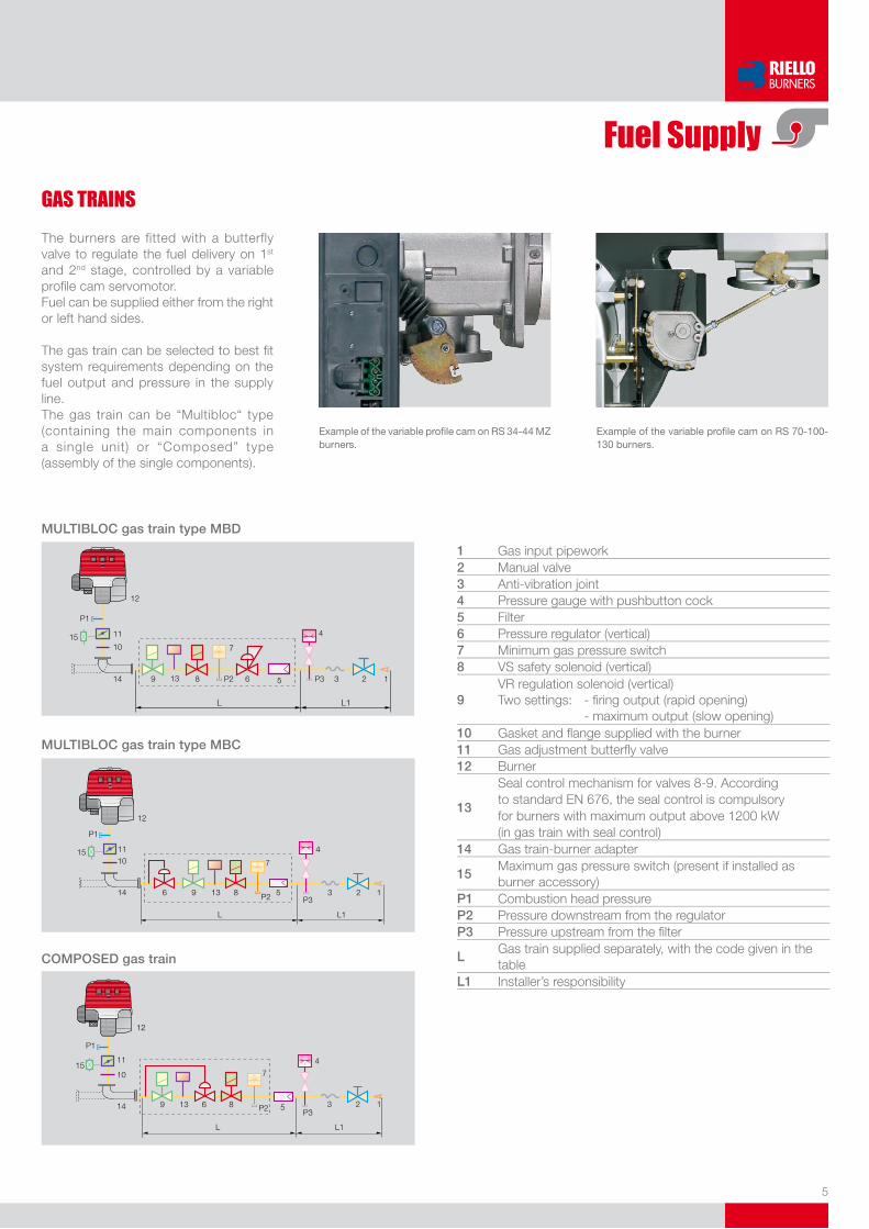
The burners are fitted with a butterfly valve to regulate the fuel delivery on 1st and �nd stage, controlled by a variable profi le cam servomotor.Fuel can be supplied either from the right or left hand sides.
The gas train can be selected to best fi t system requirements depending on the fuel output and pressure in the supply line.The gas train can be “Multibloc“ type (containing the main components in a single unit) or “Composed” type (assembly of the single components).
example of the variable profi le cam on RS 34-44 MZ burners.
example of the variable profi le cam on RS 70-100-130 burners.
L L1
12
P1
11
1015
14 9 8 P2 6 P3
4
3 2 15
7
13
MULTiBLoC gas train type MBD
CoMPoSED gas train
L L1
12
P1
1511
10
14 9 13 6 8
7
5
4
P3P2 3 2 1
MULTiBLoC gas train type MBC
12
P1
15 1110
14 6
L L1
9 13 8
7
5
4
P3P2 3 2 1
1 Gas input pipework2 Manual valve3 Anti-vibration joint4 Pressure gauge with pushbutton cock5 Filter6 Pressure regulator (vertical)7 Minimum gas pressure switch8 VS safety solenoid (vertical)
9VR regulation solenoid (vertical)Two settings: - fi ring output (rapid opening) - maximum output (slow opening)
10 Gasket and fl ange supplied with the burner11 Gas adjustment butterfl y valve12 Burner
13
Seal control mechanism for valves 8-9. Accordingto standard EN 676, the seal control is compulsoryfor burners with maximum output above 1�00 kW (in gas train with seal control)
14 Gas train-burner adapter
15Maximum gas pressure switch (present if installed as burner accessory)
P1 Combustion head pressureP2 Pressure downstream from the regulatorP3 Pressure upstream from the fi lter
LGas train supplied separately, with the code given in the table
L1 Installer’s responsibility
6
RS Series
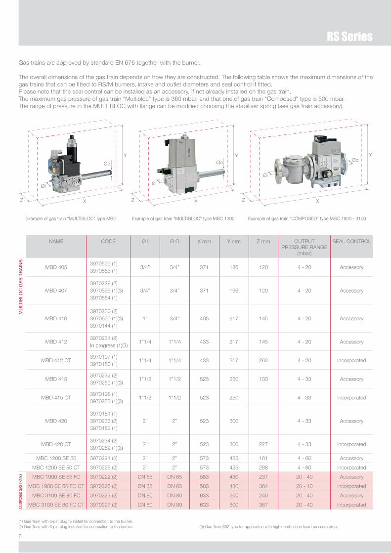
Gas trains are approved by standard EN 676 together with the burner.
The overall dimensions of the gas train depends on how they are constructed. The following table shows the maximum dimensions of the gas trains that can be fitted to RS/M burners, intake and outlet diameters and seal control if fitted.Please note that the seal control can be installed as an accessory, if not already installed on the gas train.The maximum gas pressure of gas train “Multibloc” type is 360 mbar, and that one of gas train “Composed” type is 500 mbar.The range of pressure in the MULTIBLOC with flange can be modified choosing the stabiliser spring (see gas train accessory).
Example of gas train “MULTIBLOC” type MBD Example of gas train “MULTIBLOC” type MBC 1�00
NAME CODE Ø I Ø O X mm Y mm Z mm OUTPUT PRESSURE RANGE
(mbar)
SEAL CONTROL
Mu
lTiB
loC
GA
S T
RA
iNS
MBD 4053970500 (1)3970553 (1)
3/4” 3/4” 371 186 1�0 4 - �0 Accessory
MBD 4073970��9 (�)3970599 (1)(3)3970554 (1)
3/4” 3/4” 371 196 1�0 4 - �0 Accessory
MBD 4103970�30 (�)3970600 (1)(3)3970144 (1)
1” 3/4” 405 �17 145 4 - �0 Accessory
MBD 41�3970�31 (�)In progress (1)(3)
1”1/4 1”1/4 433 �17 145 4 - �0 Accessory
MBD 41� CT3970197 (1)3970180 (1)
1”1/4 1”1/4 433 �17 �6� 4 - �0 Incorporated
MBD 4153970�3� (�)3970�50 (1)(3)
1”1/� 1”1/� 5�3 �50 100 4 - 33 Accessory
MBD 415 CT3970198 (1)3970�53 (1)(3)
1”1/� 1”1/� 5�3 �50 4 - 33 Incorporated
MBD 4�03970181 (1)3970�33 (�)397018� (1)
�” �” 5�3 300 4 - 33 Accessory
MBD 4�0 CT3970�34 (�)3970�5� (1)(3)
�” �” 5�3 300 ��7 4 - 33 Incorporated
MBC 1�00 SE 50 3970��1 (�) �” �” 573 4�5 161 4 - 60 Accessory
MBC 1�00 SE 50 CT 3970��5 (�) �” �” 573 4�5 �88 4 - 60 Incorporated
CoM
PoSe
d GA
S TR
AiNS MBC 1900 SE 65 FC 3970��� (�) DN 65 DN 65 583 430 �37 �0 - 40 Accessory
MBC 1900 SE 65 FC CT 3970��6 (�) DN 65 DN 65 583 430 364 �0 - 40 Incorporated
MBC 3100 SE 80 FC 3970��3 (�) DN 80 DN 80 633 500 �40 �0 - 40 Accessory
MBC 3100 SE 80 FC CT 3970��7 (�) DN 80 DN 80 633 500 367 �0 - 40 Incorporated
(1) Gas Train with 6-pin plug to install for connection to the burner. (�) Gas Train with 6-pin plug installed for connection to the burner. (3) Gas Train S5� type for application with high combustion head pressure drop.
Example of gas train “COMPOSED” type MBC 1900 - 3100
Z
Øi
Øo
X
Y
Z
Øi
Øo
X
Y
Z
Øi
Øo
X
Y
7
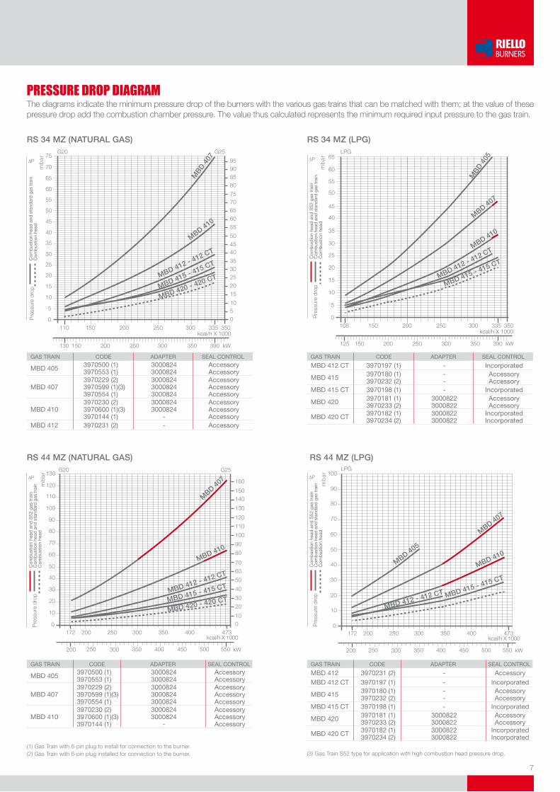
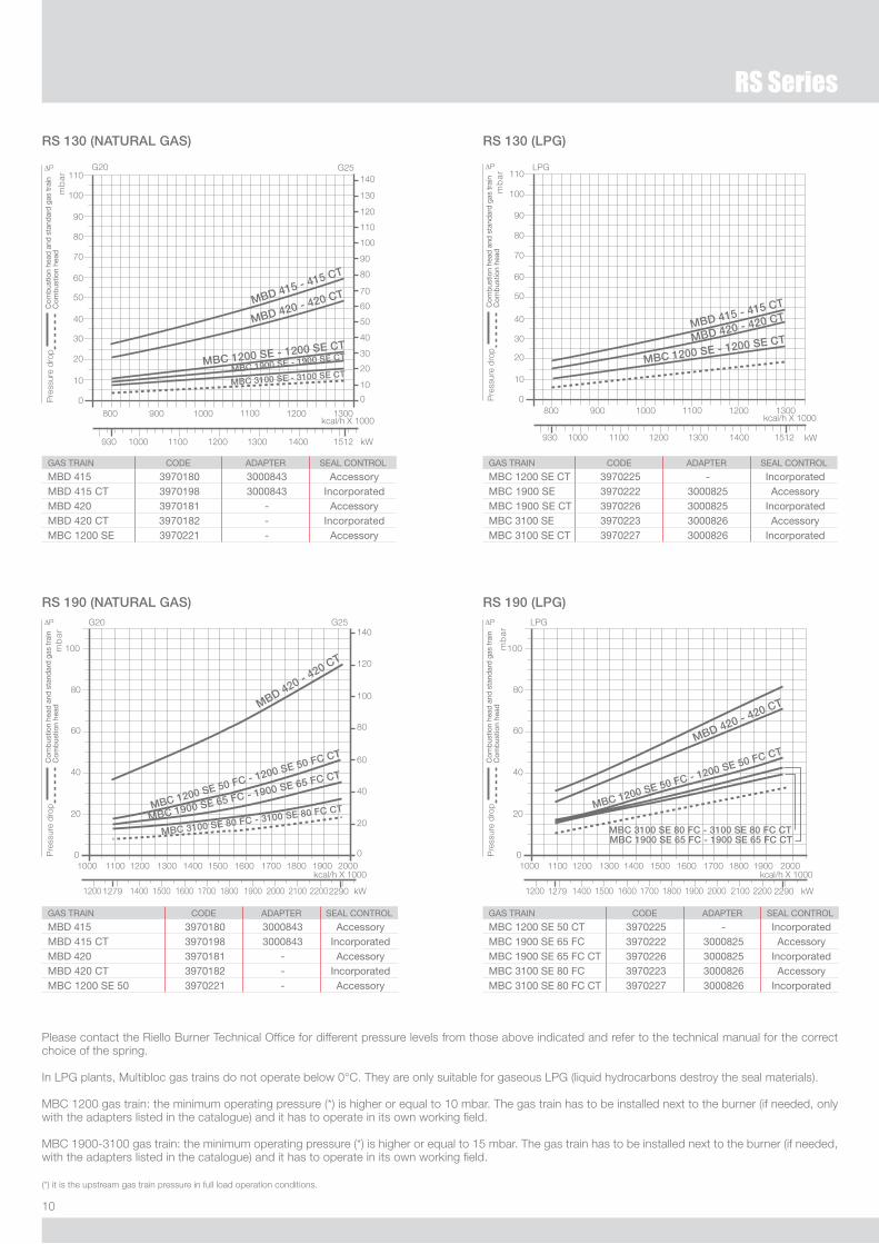
PRESSURE DROP DIAGRAMThe diagrams indicate the minimum pressure drop of the burners with the various gas trains that can be matched with them; at the value of these pressure drop add the combustion chamber pressure. The value thus calculated represents the minimum required input pressure to the gas train.
RS 34 MZ (NATURAL GAS)
(1) Gas Train with 6-pin plug to install for connection to the burner.(�) Gas Train with 6-pin plug installed for connection to the burner.
GAS TRAiN Code AdAPTeR SeAl CoNTRol
MBd 405 3970500 (1)3970553 (1)
30008243000824
AccessoryAccessory
MBd 4073970229 (2)3970599 (1)(3)3970554 (1)
300082430008243000824
AccessoryAccessoryAccessory
MBd 4103970230 (2)3970600 (1)(3)3970144 (1)
30008243000824
-
AccessoryAccessoryAccessory
MBd 412 3970231 (2) - Accessory
RS 34 MZ (LPG)
RS 44 MZ (NATURAL GAS)
GAS TRAiN Code AdAPTeR SeAl CoNTRol
MBd 405 3970500 (1)3970553 (1)
30008243000824
AccessoryAccessory
MBd 4073970229 (2)3970599 (1)(3)3970554 (1)
300082430008243000824
AccessoryAccessoryAccessory
MBd 4103970230 (2)3970600 (1)(3)3970144 (1)
30008243000824
-
AccessoryAccessoryAccessory
RS 44 MZ (LPG)
MBD 405
MBD 407
MBD 410
MBD 412 - 412 CT MBD 415 - 415 CT
GAS TRAiN Code AdAPTeR SeAl CoNTRol
MBd 412 CT 3970197 (1) - incorporated
MBd 415 3970180 (1)3970232 (2)
--
AccessoryAccessory
MBd 415 CT 3970198 (1) - incorporated
MBd 420 3970181 (1)3970233 (2)
30008223000822
AccessoryAccessory
MBd 420 CT 3970182 (1)3970234 (2)
30008223000822
incorporatedincorporated
(3) Gas Train S5� type for application with high combustion head pressure drop.
GAS TRAiN Code AdAPTeR SeAl CoNTRol
MBd 412 3970231 (2) - AccessoryMBd 412 CT 3970197 (1) - incorporated
MBd 415 3970180 (1)3970232 (2)
--
AccessoryAccessory
MBd 415 CT 3970198 (1) - incorporated
MBd 420 3970181 (1)3970233 (2)
30008223000822
AccessoryAccessory
MBd 420 CT 3970182 (1)3970234 (2)
30008223000822
incorporatedincorporated
MBD 4
05
MBD 407
MBD 410
MBD 412 - 412 CT
MBD 415 - 415 CT
MBD 4
07
MBD 410
MBD 412 - 412 CT
MBD 415 - 415 CT
MBD 420 - 420 CT
MBD 40
7
MBD 410
MBD 412 - 412 CT
MBD 415 - 415 CT
MBD 420 - 420 CT
8
RS Series
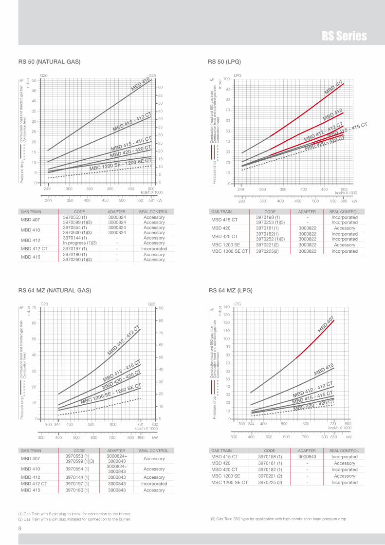
RS 50 (NATURAL GAS)
MBD 410
MBD 412 - 412 CT
MBD 415 - 415 CT
MBD 420 - 420 CT
MBC 1200 SE - 1200 SE CT
GAS TRAiN Code AdAPTeR SeAl CoNTRol
MBd 407 3970553 (1)3970599 (1)(3)
30008243000824
AccessoryAccessory
MBd 410 3970554 (1)3970600 (1)(3)
30008243000824
AccessoryAccessory
MBd 412 3970144 (1)in progress (1)(3)
--
AccessoryAccessory
MBd 412 CT 3970197 (1) - incorporated
MBd 415 3970180 (1)3970250 (1)(3)
--
AccessoryAccessory
RS 50 (LPG)
RS 64 MZ (NATURAL GAS) RS 64 MZ (LPG)
MBD 41
2 - 41
2 CT
MBD 415 - 415 CT
MBD 420 - 420 CT
MBC 1200 SE - 1200 SE CT
GAS TRAiN Code AdAPTeR SeAl CoNTRol
MBd 407 3970553 (1)3970599 (1)(3)
3000824+3000843 Accessory
MBd 410 3970554 (1) 3000824+3000843 Accessory
MBd 412 3970144 (1) 3000843 AccessoryMBd 412 CT 3970197 (1) 3000843 incorporatedMBd 415 3970180 (1) 3000843 Accessory
MBD 410
MBD 412 - 412 CT
MBD 415 - 415 CT
MBD 420 - 420 CT
MBD 4
07
GAS TRAiN Code AdAPTeR SeAl CoNTRol
MBd 415 CT 3970198 (1)3970253 (1)(3)
--
incorporatedincorporated
MBd 420 3970181(1) 3000822 Accessory
MBd 420 CT 3970182(1)3970252 (1)(3)
30008223000822
incorporatedincorporated
MBC 1200 Se 3970221(2) 3000822 AccessoryMBC 1200 Se CT 3970225(2) 3000822 incorporated
(1) Gas Train with 6-pin plug to install for connection to the burner.(�) Gas Train with 6-pin plug installed for connection to the burner. (3) Gas Train S5� type for application with high combustion head pressure drop.
MBD 410
MBD 415 - 415 CT
MBD 407
MBD 412 - 412 CT
MBD 420 - 420 CT
GAS TRAiN Code AdAPTeR SeAl CoNTRol
MBd 415 CT 3970198 (1) 3000843 incorporatedMBd 420 3970181 (1) - AccessoryMBd 420 CT 3970182 (1) - incorporatedMBC 1200 Se 3970221 (2) - AccessoryMBC 1200 Se CT 3970225 (2) - incorporated
9
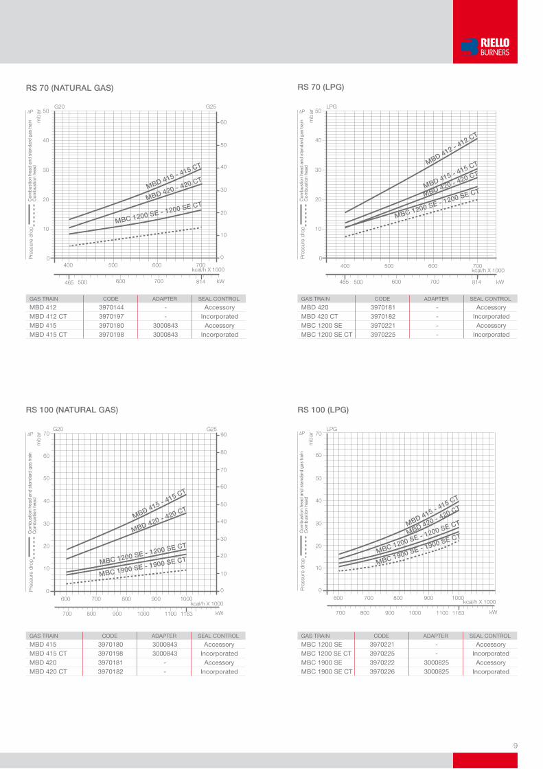
RS 70 (NATURAL GAS) RS 70 (LPG)
MBD 415 - 415 CT
MBD 420 - 420 CT
MBC 1200 SE - 1200 SE CT
MBD 415 - 415 CT
MBD 420 - 420 CT
MBC 1200 SE - 1200 SE CT
MBD 412 - 412 CT
GAS TRAiN Code AdAPTeR SeAl CoNTRol
MBd 412 3970144 - AccessoryMBd 412 CT 3970197 - incorporatedMBd 415 3970180 3000843 AccessoryMBd 415 CT 3970198 3000843 incorporated
GAS TRAiN Code AdAPTeR SeAl CoNTRol
MBd 420 3970181 - AccessoryMBd 420 CT 3970182 - incorporatedMBC 1200 Se 3970221 - AccessoryMBC 1200 Se CT 3970225 - incorporated
RS 100 (NATURAL GAS) RS 100 (LPG)
MBD 415 - 415 CT
MBD 420 - 420 CT
MBC 1200 SE - 1200 SE CT
MBC 1900 SE - 1900 SE CT
GAS TRAiN Code AdAPTeR SeAl CoNTRol
MBd 415 3970180 3000843 AccessoryMBd 415 CT 3970198 3000843 incorporatedMBd 420 3970181 - AccessoryMBd 420 CT 3970182 - incorporated
MBD 415 - 415 CT
MBD 420 - 420 CT
MBC 1200 SE - 1200 SE CT
MBC 1900 SE - 1900 SE CT
GAS TRAiN Code AdAPTeR SeAl CoNTRol
MBC 1200 Se 3970221 - AccessoryMBC 1200 Se CT 3970225 - incorporatedMBC 1900 Se 3970222 3000825 AccessoryMBC 1900 Se CT 3970226 3000825 incorporated
10
RS Series
RS 130 (NATURAL GAS) RS 130 (LPG)
MBD 415 - 415 CT
MBD 420 - 420 CT
MBC 1200 SE - 1200 SE CT
MBC 1900 SE - 1900 SE CT
MBC 3100 SE - 3100 SE CT
MBD 415 - 415 CT
MBD 420 - 420 CT
MBC 1200 SE - 1200 SE CT
GAS TRAiN Code AdAPTeR SeAl CoNTRol
MBd 415 3970180 3000843 AccessoryMBd 415 CT 3970198 3000843 incorporatedMBd 420 3970181 - AccessoryMBd 420 CT 3970182 - incorporatedMBC 1200 Se 3970221 - Accessory
GAS TRAiN Code AdAPTeR SeAl CoNTRol
MBC 1200 Se CT 3970225 - incorporatedMBC 1900 Se 3970222 3000825 AccessoryMBC 1900 Se CT 3970226 3000825 incorporatedMBC 3100 Se 3970223 3000826 AccessoryMBC 3100 Se CT 3970227 3000826 incorporated
Please contact the Riello Burner Technical Office for different pressure levels from those above indicated and refer to the technical manual for the correct choice of the spring.
In LPG plants, Multibloc gas trains do not operate below 0°C. They are only suitable for gaseous LPG (liquid hydrocarbons destroy the seal materials).
MBC 1�00 gas train: the minimum operating pressure (*) is higher or equal to 10 mbar. The gas train has to be installed next to the burner (if needed, only with the adapters listed in the catalogue) and it has to operate in its own working field.
MBC 1900-3100 gas train: the minimum operating pressure (*) is higher or equal to 15 mbar. The gas train has to be installed next to the burner (if needed, with the adapters listed in the catalogue) and it has to operate in its own working field.
(*) it is the upstream gas train pressure in full load operation conditions.
RS 190 (NATURAL GAS) RS 190 (LPG)
MBD 420 - 420 CT
MBC 1200 SE 50 FC - 1200 SE 50 FC CT
MBC 1900 SE 65 FC - 1900 SE 65 FC CT
MBC 3100 SE 80 FC - 3100 SE 80 FC CT
MBD 420 - 420 CT
MBC 1200 SE 50 FC - 1200 SE 50 FC CT
MBC 1900 SE 65 FC - 1900 SE 65 FC CTMBC 3100 SE 80 FC - 3100 SE 80 FC CT
GAS TRAiN Code AdAPTeR SeAl CoNTRol
MBd 415 3970180 3000843 AccessoryMBd 415 CT 3970198 3000843 incorporatedMBd 420 3970181 - AccessoryMBd 420 CT 3970182 - incorporatedMBC 1200 Se 50 3970221 - Accessory
GAS TRAiN Code AdAPTeR SeAl CoNTRol
MBC 1200 Se 50 CT 3970225 - incorporatedMBC 1900 Se 65 FC 3970222 3000825 AccessoryMBC 1900 Se 65 FC CT 3970226 3000825 incorporatedMBC 3100 Se 80 FC 3970223 3000826 AccessoryMBC 3100 Se 80 FC CT 3970227 3000826 incorporated

11
SELECTING THE FUEL SUPPLY LINES
The following diagram enables pressure drop in a pre-existing gas line to be calculated and to select the correct gas train.The diagram can also be used to select a new gas line when fuel output and pipe length are known. The pipe diameter is selected on the basis of the desired pressure drop. The diagram uses methane gas as reference; if another gas is used, conversion coefficient and a simple formula (on the diagram) transform the gas output to a methane equivalent (refer to figure A). Please note that the gas train dimensions must take into account the back pressure of the combustion chamber during operations.
Control of the pressure drop in an existing gas line or selecting a new gas supply line.The methane output equivalent is determined by the formula fig. A on the diagram and the conversion coefficient.
Once the equivalent output has been determined on the delivery scale ( ), shown at the top of the diagram, move vertically downwards until you cross the line that represents the pipe diameter; at this point, move horizontally to the left until you meet the line that represents the pipe length.Once this point is established you can verify, by moving vertically downwards, the pipe pressure drop of on the botton scale below (mbar).By subtracting this value from the pressure measured on the gas
meter, the correct pressure value will be found for the choice of gas train.
Example: - gas used G�5 - gas output 9.51 mc/h - pressure at the gas meter �0 mbar - gas line length 15 m - conversion coefficient 0.6� (see figure A)
- equivalent methane output = 9.51 = 15.34 mc/h 0.6�
- once the value of 15.34 has been identified on the output scale ( ), moving vertically downwards you cross the line that represents 1” 1/4 (the chosen diameter for the piping);
- from this point, move horizontally to the left until you meet the line that represents the length of 15 m of the piping;
- move vertically downwards to determine a value of 1.4 mbar in the pressure drop botton scale;
- subtract the determined pressure drop from the meter pressure, the correct pressure level will be found for the choice of gas train;
- correct pressure = ( �0-1.4 ) = 18.6 mbar
1�
RS Series
Ventilation
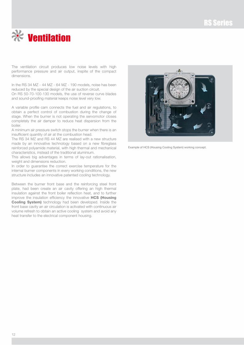
The ventilation circuit produces low noise levels with high performance pressure and air output, inspite of the compact dimensions.
In the RS 34 MZ - 44 MZ - 64 MZ - 190 models, noise has been reduced by the special design of the air suction circuit.On RS 50-70-100-130 models, the use of reverse curve blades and sound-proofing material keeps noise level very low.
A variable profile cam connects the fuel and air regulations, to obtain a perfect control of combustion during the change of stage. When the burner is not operating the servomotor closes completely the air damper to reduce heat dispersion from the boiler.A minimum air pressure switch stops the burner when there is an insufficient quantity of air at the combustion head.The RS 34 MZ and RS 44 MZ are realised with a new structure made by an innovative technology based on a new fibreglass reinforced polyamide material, with high thermal and mechanical characteristics, instead of the traditional aluminium. This allows big advantages in terms of lay-out rationalisation, weight and dimensions reduction.In order to guarantee the correct exercise temperature for the internal burner components in every working conditions, the new structure includes an innovative patented cooling technology.
Between the burner front base and the reinforcing steel front plate, had been create an air cavity offering an high thermal insulation against the front boiler reflection heat, and to further improve the insulation efficiency the innovative HCS (Housing Cooling System) technology had been developed. Inside the front base cavity an air circulation is activated with continuous air volume refresh to obtain an active cooling system and avoid any heat transfer to the electrical component housing.
example of HCS (Housing Cooling System) working concept.
13
Combustion Head
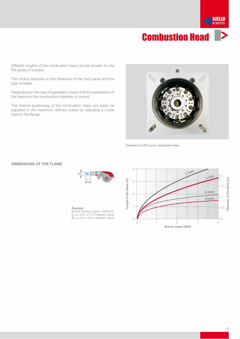
Different lengths of the combustion head can be chosen for the RS series of burners.
The choice depends on the thickness of the front panel and the type of boiler.
Depending on the type of generator, check that the penetration of the head into the combustion chamber is correct.
The internal positioning of the combustion head can easily be adjusted to the maximum defined output by adjusting a screw fixed to the flange.
example of a RS burner combustion head.
Example: Burner thermal output = �000 kW;L flame (m) = �,7 m (medium value);D flame (m) = 0,8 m (medium value)
�
�
DiMENSioNS oF ThE FLAME
Burner output (MW)
Leng
ht o
f th
e fla
me
(m)
Dia
met
er o
f th
e fla
me
(m)
L max
L min
D max
D min

14
RS Series
Operation
BURNER OPERATION MODE
On “two stage” operation, the burner gradually adapts the output to the requested level, by varying between two pre-set levels (see picture A).
Picture A
“TWo STAGE” oPERATioN
All RS series burners are fitted with a new microprocessor control panel for the supervision during intermittent operation.For helping the commissioning and maintenance work, there are two main elements:
The lock-out reset button is the central operating element for resetting the burner control and for activating / deactivating the diagnostic functions.
The multi-color LED is the central indication element for visual diagnosis and interface diagnosis.
Both elements are located under the transparent cover of lock-out reset button, as showed below.
There are two diagnostic choices, for indication of operation and diagnosis of fault cause:
viSUAL DiAGNoSiS
15
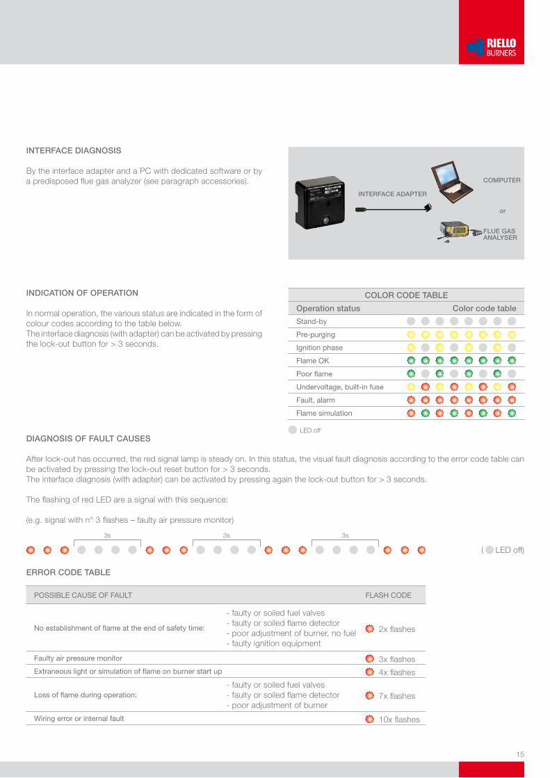
iNTERFACE DiAGNoSiS
By the interface adapter and a PC with dedicated software or by a predisposed flue gas analyzer (see paragraph accessories).
iNDiCATioN oF oPERATioN
In normal operation, the various status are indicated in the form of colour codes according to the table below.The interface diagnosis (with adapter) can be activated by pressing the lock-out button for > 3 seconds.
CoMPUTER
or
FLUE GASANALySER
iNTERFACE ADAPTER
CoLoR CoDE TABLE
operation status Color code table
Stand-by
Pre-purging
ignition phase
Flame oK
Poor flame
undervoltage, built-in fuse
Fault, alarm
Flame simulation
LED offDiAGNoSiS oF FAULT CAUSES
After lock-out has occurred, the red signal lamp is steady on. In this status, the visual fault diagnosis according to the error code table can be activated by pressing the lock-out reset button for > 3 seconds.The interface diagnosis (with adapter) can be activated by pressing again the lock-out button for > 3 seconds.
The flashing of red LED are a signal with this sequence:
(e.g. signal with n° 3 flashes – faulty air pressure monitor)
( LED off)
3s 3s 3s
ERRoR CoDE TABLE
PoSSiBle CAuSe oF FAulT FlASH Code
No establishment of flame at the end of safety time:
- faulty or soiled fuel valves- faulty or soiled flame detector- poor adjustment of burner, no fuel- faulty ignition equipment
�x flashes
Faulty air pressure monitor 3x flashesextraneous light or simulation of flame on burner start up 4x flashes
loss of flame during operation:- faulty or soiled fuel valves- faulty or soiled flame detector- poor adjustment of burner
7x flashes
Wiring error or internal fault 10x flashes

16
RS Series
START UP CYCLE
RS 34 MZ - 44 MZ - 50 - 64 MZ - 100 - 130 - 190
0 s The burner begins the firing cycle.� s The motor starts: pre-purge phase.43 s Ignition electrode sparks; safety valve VS and
adjustment valve VR open.45 s The spark goes out.53 s Output can be increased; start up cycle is concluded.
time (s)
0
45
Tl
TR
M
VRVS
2°1°0
2°1°0
RMGled
3
2
43
283
53
46
M
Off Yellow Green
Burner Wiring
All models of the RS burner series have an easily accessible control panel for the electrical components housing and wiring. In particular the RS 34-44 MZ models, thanks to the new structure concept, have a extremely clean electrical layout to optimise the commissioning and maintenance speed. On these models the electrical connection are done by a Plug&Socket system, accessible from the external of the cover, and some of the main components as the servomotor, the air pressure switch and the gas max pressure switch (accessory) are connected to the burner electrical wiring trough plugs & sockets system in order to facilitate the connection in case of maintenance. The electrical wiring of all RS burner models are very easy to do following the wiring diagrams included in the instruction handbook. Electrical connections must be made by qualified and skilled personnel, according to the local norms.
example of plugs and sockets for electrical connections for the RS 50 model.
example of electrical components housing and Plug&Socket system for electrical connection of RS 34-44 MZ.
17
NO� Emissions
CO Emissions
Noise Emissions
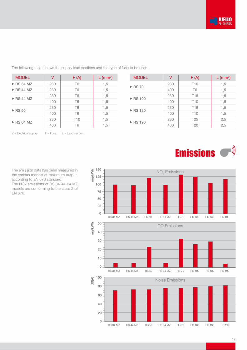
The following table shows the supply lead sections and the type of fuse to be used.
Model V F (A) l (mm2)u RS 34 MZ 230 T6 1,5
u RS 44 MZ 230 T6 1,5
u RS 44 MZ 230 T6 1,5
400 T6 1,5
u RS 50 230 T6 1,5
400 T6 1,5
u RS 64 MZ 230 T10 1,5
400 T6 1,5
Model V F (A) l (mm2)
u RS 70 230 T10 1,5
400 T6 1,5
u RS 100 230 T16 1,5
400 T10 1,5
u RS 130 230 T16 1,5
400 T10 1,5
u RS 190 230 T25 2,5
400 T20 2,5
V = Electrical supply F = Fuse L = Lead section
Emissions
The emission data has been measured in the various models at maximum output, according to EN 676 standard.The NOx emissions of RS 34-44-64 MZ models are conforming to the class � of EN 676.
150
125
100
75
50
25
0
mg
/kW
h
50
40
30
20
10
0
mg
/kW
h
100
80
60
40
20
0
dB
(A)

18
RS Series
Overall Dimensions (mm)
BURNERS
Model A d e F G - G(1) H i l M N o S u RS 34 MZ 442 422 508 138 216 - 351 140 305 177 1”1/2 84 780 -
u RS 44 MZ 442 422 508 138 216 - 351 152 305 177 1”1/2 84 780 -
u RS 50 476 474 580 164 216 - 351 152 352 168 1”1/2 108 810 367
RS 34 MZ - 44 MZ RS 50
(1) dimension with extended head
RS 64 MZ RS 70 - 100 - 130 - 190
Model A B C d e F G - G(1) H i l M N o - o(1)u RS 64 MZ 533 300 - 490 640 222 250 - 385 179 352 221 2” 134 810 - -
u RS 70 511 296 215 555 840 214 250 - 385 179 430 221 2” 134 1161 - 1296
u RS 100 527 312 215 555 840 214 250 - 385 179 430 221 2” 134 1161 - 1296
u RS 130 553 338 215 555 840 214 280 - 415 189 430 221 2” 134 1161 - 1296
u RS 190 681 366 315 555 856 230 372 - 530 222 430 221 2” 150 1312 - -
(1) dimension with extended head
�
�
�
������
�
�
�
�
��
�
�
�
�
�
������
�
�
�
��
�
�
�
�
���������
�
�
� �
�
�
�
����������
�
�
�
������
�
�
�
��
�
�
�
�

19
BURNER - BOILER MOUNTING FLANGE
Model d1 d2 Ø u RS 34 MZ 160 224 M8
u RS 44 MZ 160 224 M8
u RS 50 160 224 M8
u RS 64 MZ 185 275-325 M12
u RS 70 185 275-325 M12
u RS 100 185 275-325 M12
u RS 130 195 275-325 M12
u RS 190 230 325-368 M16
PACKAGING
Model X (1) Y Z kgu RS 34 MZ 1000 485 500 32
u RS 44 MZ 1000 485 500 33
u RS 50 1200 502 520 41
u RS 64 MZ 1200 580 520 42
u RS 70 1405 700 660 70
u RS 100 1405 700 660 73
u RS 130 1405 700 660 76
u RS 190 1405-1420 1000 660 82
Z
X (1)Y
(1) dimension with standard and extended head
�0
RS Series
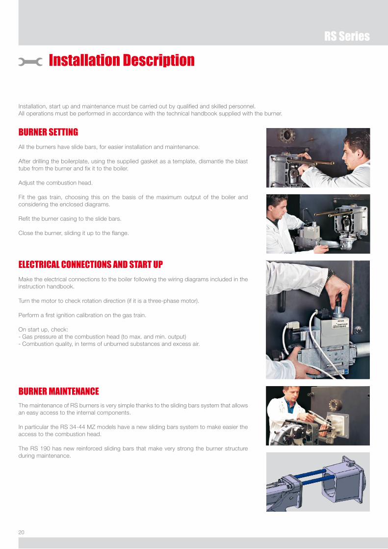
Installation Description
Installation, start up and maintenance must be carried out by qualified and skilled personnel.All operations must be performed in accordance with the technical handbook supplied with the burner.
BURNER SETTINGAll the burners have slide bars, for easier installation and maintenance.
After drilling the boilerplate, using the supplied gasket as a template, dismantle the blast tube from the burner and fix it to the boiler.
Adjust the combustion head.
Fit the gas train, choosing this on the basis of the maximum output of the boiler and considering the enclosed diagrams.
Refit the burner casing to the slide bars.
Close the burner, sliding it up to the flange.
ELECTRICAL CONNECTIONS AND START UPMake the electrical connections to the boiler following the wiring diagrams included in the instruction handbook.
Turn the motor to check rotation direction (if it is a three-phase motor).
Perform a first ignition calibration on the gas train.
On start up, check:- Gas pressure at the combustion head (to max. and min. output)- Combustion quality, in terms of unburned substances and excess air.
The maintenance of RS burners is very simple thanks to the sliding bars system that allows an easy access to the internal components.
In particular the RS 34-44 MZ models have a new sliding bars system to make easier the access to the combustion head.
The RS 190 has new reinforced sliding bars that make very strong the burner structure during maintenance.
BURNER MAINTENANCE
�1
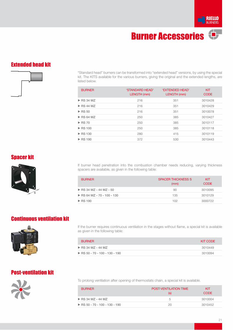
Burner Accessories
Spacer kitIf burner head penetration into the combustion chamber needs reducing, varying thickness spacers are available, as given in the following table:
BuRNeR SPACeR THiCKNeSS S (mm)
KiT Code
u RS 34 MZ - 44 MZ - 50 90 3010095
u RS 64 MZ - 70 - 100 - 130 135 3010129
u RS 190 102 3000722
Continuous ventilation kitIf the burner requires continuous ventilation in the stages without flame, a special kit is available as given in the following table:
BuRNeR KiT Code
u RS 34 MZ - 44 MZ 3010449
u RS 50 - 70 - 100 - 130 - 190 3010094
Extended head kit“Standard head” burners can be transformed into “extended head” versions, by using the special kit. The KITS available for the various burners, giving the original and the extended lengths, are listed below.
BuRNeR ‘STANdARd HeAd’ leNGTH (mm)
‘eXTeNded HeAd’ leNGTH (mm)
KiT Code
u RS 34 MZ 216 351 3010428
u RS 44 MZ 216 351 3010429
u RS 50 216 351 3010078
u RS 64 MZ 250 385 3010427
u RS 70 250 385 3010117
u RS 100 250 385 3010118
u RS 130 280 415 3010119
u RS 190 372 530 3010443
Post-ventilation kitTo prolong ventilation after opening of thermostats chain, a special kit is available.
BuRNeR PoST-VeNTilATioN TiMe (s)
KiT Code
u RS 34 MZ - 44 MZ 5 3010004
u RS 50 - 70 - 100 - 130 - 190 20 3010452
��
RS Series
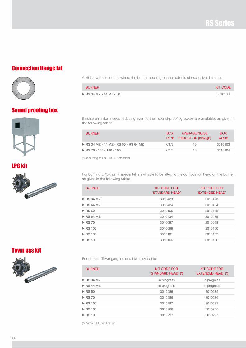
LPG kitFor burning LPG gas, a special kit is available to be fitted to the combustion head on the burner, as given in the following table:
BuRNeR KiT Code FoR‘STANdARd HeAd’
KiT Code FoR‘eXTeNded HeAd’
u RS 34 MZ 3010423 3010423
u RS 44 MZ 3010424 3010424
u RS 50 3010165 3010165
u RS 64 MZ 3010434 3010435
u RS 70 3010097 3010098
u RS 100 3010099 3010100
u RS 130 3010101 3010102
u RS 190 3010166 3010166
Town gas kitFor burning Town gas, a special kit is available:
BuRNeR KiT Code FoR‘STANdARd HeAd’ (*)
KiT Code FoR‘eXTeNded HeAd’ (*)
u RS 34 MZ in progress in progress
u RS 44 MZ in progress in progress
u RS 50 3010285 3010285
u RS 70 3010286 3010286
u RS 100 3010287 3010287
u RS 130 3010288 3010288
u RS 190 3010297 3010297
(*) Without CE certification
Connection flange kit
BuRNeR KiT Code
u RS 34 MZ - 44 MZ - 50 3010138
A kit is available for use where the burner opening on the boiler is of excessive diameter.
Sound proofing boxIf noise emission needs reducing even further, sound-proofing boxes are available, as given in the following table:
BuRNeR BoX TYPe
AVeRAGe NoiSe ReduCTioN [dB(A)](*)
BoX Code
u RS 34 MZ - 44 MZ - RS 50 - RS 64 MZ C1/3 10 3010403
u RS 70 - 100 - 130 - 190 C4/5 10 3010404
(*) according to EN 15036-1 standard

�3
Vibration reduction kitThe kit allow you to improve flame stability in some applications, where the boiler/flue assembly is liable to resonate.
BuRNeR KiT Code
u RS 50 TC - RS 50 TL 3010200
u RS 70 TC - RS 70 TL 3010201
u RS 100 TC - RS 100 TL 3010202
u RS 130 TC 3010373
u RS 130 TL 3010374
u RS 190 TC 3010375
Status Panel kitThe RS burners can be equipped with an exclusive electronic device “Status Panel” which continuously monitors and displays all the burner operational modes and picks up any anomalies during the operational cycle.
BuRNeR KiT Code
u RS 50 - 64 MZ - 70 - 100 - 130 - 190 3010322
Ground fault interrupter kitA “Ground fault interrupter kit” is available as a safety device for electrical system fault.
BuRNeR KiT Code
u RS 34 MZ - 44 MZ 3010448
u RS 50 - RS 64 MZ 3010321
u RS 70 - 100 - 130 - 190 3010329
Gas max pressure switchIf necessary a Gas max pressure Switch kit is available and connectable to the burner electrical wiring trough Plugs & Sockets system.
BuRNeR KiT Code
u RS 34 MZ - 44 MZ 3010418
50 45
40
5
3530
2520
10
15
2,5
Volt free contact kitA volt free contact kit is available for installation onto the burner. It can be used for a remote interface between burner operating signals. Every burner can be equipped with a single kit for a remote check of the flame presence signal and the burner lockout indication.
BuRNeR KiT Code
u RS 34 MZ - 44 MZ - 64 MZ 3010419
�4
RS Series
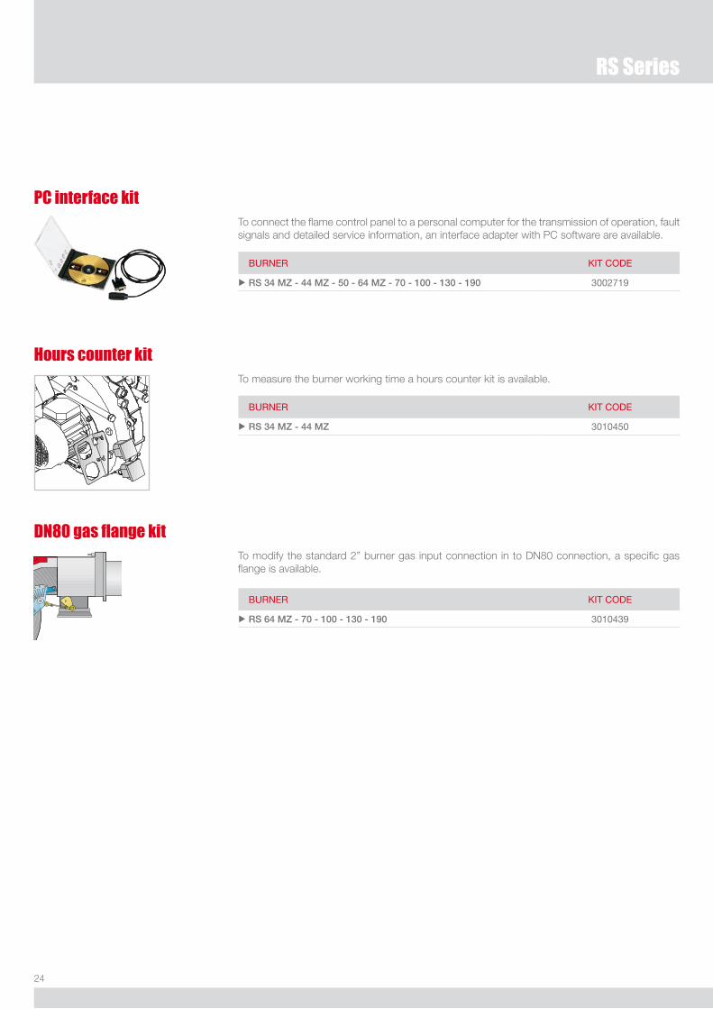
PC interface kitTo connect the flame control panel to a personal computer for the transmission of operation, fault signals and detailed service information, an interface adapter with PC software are available.
BuRNeR KiT Code
u RS 34 MZ - 44 MZ - 50 - 64 MZ - 70 - 100 - 130 - 190 3002719
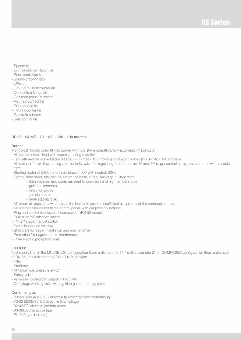
DN80 gas flange kit To modify the standard �” burner gas input connection in to DN80 connection, a specific gas flange is available.
BuRNeR KiT Code
u RS 64 MZ - 70 - 100 - 130 - 190 3010439
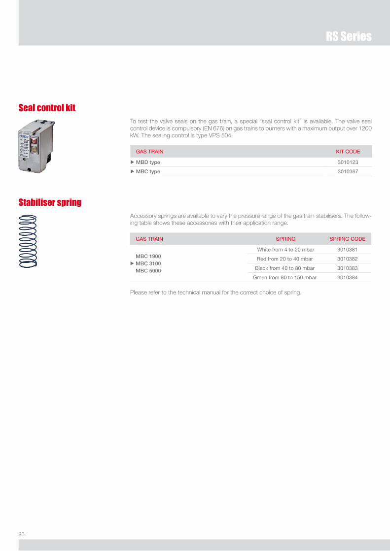
Hours counter kitTo measure the burner working time a hours counter kit is available.
BuRNeR KiT Code
u RS 34 MZ - 44 MZ 3010450

�5
Gas Train Accessories
AdaptersWhen the diameter of the gas train is different from the set diameter of the burners, an adapter must be fitted between the gas train and the burner. The following table lists the adapters for various burners.
BuRNeR GAS TRAiN diMeNSioNS AdAPTeR Code
u RS 34 MZ MBd 405 - 407 - 410 1” 1/�3/4” 3000824
MBd 420 1” 1/��” 3000822
u RS 44 MZMBd 405 - 407 - 410 1” 1/�3/4” 3000824
MBd 420 1” 1/��” 3000822
u RS 50MBd 407 - 410 1” 1/�3/4” 3000824
MBd 420 - MBC 1200 1” 1/��” 3000822
u RS 64 MZMBd 407 - 410
1” 1/�3/4”
�”1” 1/�
3000824
3000843
MBd 412 - 415 �”1” 1/� 3000843
u RS 70
MBd 415 �”1” 1/� 3000843
MBC 1900 �” 1/�DN 65
1” 1/�
�”
3000825
MBC 3100 �” 1/�DN 80 �” 3000826
u RS 100
MBd 415 �”1” 1/� 3000843
MBC 1900 �” 1/�DN 65
1” 1/�
�”
3000825
MBC 3100 �” 1/�DN 80 �” 3000826
u RS 130
MBd 415 �”1” 1/� 3000843
MBC 1900 �” 1/�DN 65
1” 1/�
�”
3000825
MBC 3100 �” 1/�DN 80 �” 3000826
u RS 190
MBd 415 �”1” 1/� 3000843
MBC 1900 �” 1/�DN 65
1” 1/�
�”
3000825
MBC 3100 �” 1/�DN 80 �” 3000826
�6
RS Series
Stabiliser springAccessory springs are available to vary the pressure range of the gas train stabilisers. The follow-ing table shows these accessories with their application range.
Please refer to the technical manual for the correct choice of spring.
GAS TRAiN SPRiNG SPRiNG Code
u
MBC 1900 MBC 3100 MBC 5000
White from 4 to 20 mbar 3010381
Red from 20 to 40 mbar 3010382
Black from 40 to 80 mbar 3010383
Green from 80 to 150 mbar 3010384
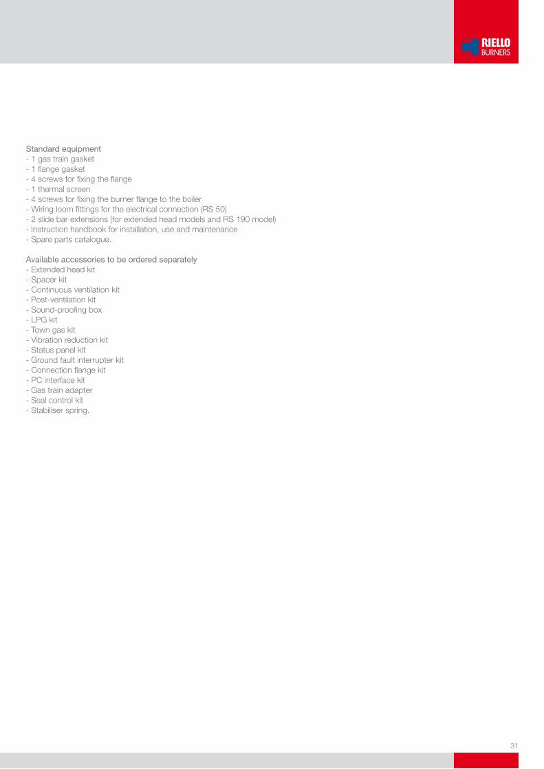
Seal control kitTo test the valve seals on the gas train, a special “seal control kit” is available. The valve seal control device is compulsory (EN 676) on gas trains to burners with a maximum output over 1�00 kW. The sealing control is type VPS 504.
GAS TRAiN KiT Code
u MBD type 3010123
u MBC type 3010367

�7
Specification
A specific index guides your choice of burner from the various models available in the RS series.Below is a clear and detailed specification description of the product.
BASiC deSiGNATioN
eXTeNded deSiGNATioN
R S 130 TC FS1 3/230-400/50 230/50-60
DESIGNATION OF SERIES
Series: R Fuel: S Natural Gas SP lPG l light oil lS light oil/Methane N Heavy oil
Size Setting: /1 Single stage ... Two stage /M Modulating emission: ... Class 1 eN267 - eN676 MZ Class 2 eN267 - eN676 Blu Class 3 eN267 - eN676
MX Class 1 eN267
Class 3 eN676 Head length: TC standard head Tl extended head Flame control system: FS1 Standard (1 stop every 24 h) FS2 Continuous working (1 stop every 72 h) electrical supply to the system: 1/230/50 1/230V/50Hz 1/220-230/50-60 1/220-230V/50-60Hz 3/230/50 3/230V/50Hz 3/400/50 3N/400V/50Hz 3/230-400/50 3/230V/50Hz - 3N/400V/50Hz 3/220/60 3/220V/60Hz 3/380/60 3N/380V/60Hz 3/220-380/60 3/220V/60Hz - 3N/380V/60Hz
3/220-400/50-60 3/220-230V/50-60Hz
3/380-400V/50-60Hz
Auxiliary voltage: 230/50-60 230V/50-60Hz 220-230/50-60 220-230V/50-60Hz 110/50-60 110V/50-60Hz
id: differential switch

�8
RS Series
AVAILABLE BURNER MODELS
RS 34 MZ TC FS1 1/220-230/50-60 220-230/50-60RS 34 MZ Tl FS1 1/220-230/50-60 220-230/50-60
RS 44 MZ TC FS1 1/220-230/50-60 220-230/50-60RS 44 MZ Tl FS1 1/220-230/50-60 220-230/50-60RS 44 MZ TC FS1 3/220-400/50-60 220-230/50-60RS 44 MZ Tl FS1 3/220-400/50-60 220-230/50-60
RS 50 TC FS1 3/230-400/50 230/50-60RS 50 Tl FS1 3/230-400/50 230/50-60RS 50 TC FS1 3/220-230/380-400/60 230/50-60RS 50 Tl FS1 3/220-230/380-400/60 230/50-60RS 50 TC FS1 3/254-265/440-460/60 230/50-60RS 50 Tl FS1 3/254-265/440-460/60 230/50-60
RS 64 MZ TC FS1 3/230-400/50 230/50-60RS 64 MZ Tl FS1 3/230-400/50 230/50-60
RS 70 TC FS1 3/230-400/50 230/50-60RS 70 Tl FS1 3/230-400/50 230/50-60RS 70 TC FS1 3/220-230/380-400/60 230/50-60RS 70 Tl FS1 3/220-230/380-400/60 230/50-60RS 70 TC FS1 3/254-265/440-460/60 230/50-60RS 70 Tl FS1 3/254-265/440-460/60 230/50-60
RS 100 TC FS1 3/230-400/50 230/50-60RS 100 Tl FS1 3/230-400/50 230/50-60RS 100 TC FS1 3/220-230/380-400/60 230/50-60RS 100 Tl FS1 3/220-230/380-400/60 230/50-60RS 100 TC FS1 3/254-265/440-460/60 230/50-60RS 100 Tl FS1 3/254-265/440-460/60 230/50-60
RS 130 TC FS1 3/230-400/50 230/50-60RS 130 Tl FS1 3/230-400/50 230/50-60RS 130 TC FS1 3/220-230/380-400/60 230/50-60RS 130 Tl FS1 3/220-230/380-400/60 230/50-60RS 130 TC FS1 3/254-265/440-460/60 230/50-60RS 130 Tl FS1 3/254-265/440-460/60 230/50-60
RS 190 TC FS1 3/230-400/50 230/50-60RS 190 TC FS1 3/220-230/380-400/60 230/50-60RS 190 TC FS1 3/254-265/440-460/60 230/50-60
Other versions are available on request.

�9
PRODUCT SPECIFICATION
RS 34 MZ - 44 MZ models
BurnerMonoblock forced draught gas burner with two stage operation, fully automatic, made up of:- Air suction circuit- High performance fan with straight blades - Air damper for air flow setting and butterfly valve for regulating fuel output on 1st and �nd stage controlled by a servomotor with variable
cam- Starting motor at �800 rpm, single-phase / ��0-�30V / 50-60Hz or three-phase / 380-400V / 50-60Hz- Combustion head, that can be set on the basis of required output, fitted with: - stainless steel end cone, resistant to corrosion and high temperatures - ignition electrodes - ionisation probe - gas distributor - flame stability disk- Exclusive patented HCS (Housing Cooling System) with high thermal insulation and air circulation with continuous air volume refresh for an
active cooling system and avoid heat transfer to the electrical component housing- Minimum air pressure switch stops the burner in case of insufficient air quantity at the combustion head- Microprocessor-based flame control panel, with diagnostic functions- Plug and socket for electrical connections accessible from the external of the cover- Burner on/off selection switch- 1st - �nd stage manual switch- Flame inspection window- Slide bars for easier installation and maintenance- Protection filter against radio interference- IP X0D (IP 40) electric protection level.
Gas trainFuel supply line, in the MULTIBLOC configuration (from a diameter of 3/4” until a diameter �”) or COMPOSED configuration (from a diameter of DN 65 until a diameter of DN 100), fitted with:- Filter- Stabiliser- Minimum gas pressure switch- Safety valve- Valve seal control (for output > 1�00 kW)- One stage working valve with ignition gas output regulator.
Conforming to:- 89/336 (�004/108) EC directive (electromagnetic compatibility)- 73/�3 (�006/95) EC directive (low voltage)- 9�/4�/EC directive (performance)- 90/396/EC directive (gas)- EN 676 (gas burners).
Standard equipment- 1 gas train gasket - 1 flange gasket- 4 screws for fixing the flange- 1 thermal screen- 4 screws for fixing the burner flange to the boiler- 3 plugs for electrical connection (RS 34 - 44 MZ single-phase)- 4 plugs for electrical connection (RS 44 MZ three-phase)- Instruction handbook for installation, use and maintenance- Spare parts catalogue.
Available accessories to be ordered separately- Extended head kit
30
RS Series
- Spacer kit- Continuous ventilation kit- Post-ventilation kit- Sound-proofing box- LPG kit- Ground fault interrupter kit- Connection flange kit- Gas max pressure switch- Volt free contact kit - PC interface kit- Hours counter kit- Gas train adapter- Seal control kit.
RS 50 - 64 MZ - 70 - 100 - 130 - 190 models
BurnerMonoblock forced draught gas burner with two stage operation, fully automatic, made up of:- Air suction circuit lined with sound-proofing material- Fan with reverse curve blades (RS 50 - 70 - 100 - 130 models) or straight blades (RS 64 MZ - 190 models)- Air damper for air flow setting and butterfly valve for regulating fuel output on 1st and �nd stage controlled by a servomotor with variable
cam- Starting motor at �800 rpm, three-phase 400V with neutral, 50Hz- Combustion head, that can be set on the basis of required output, fitted with: - stainless steel end cone, resistant to corrosion and high temperatures - ignition electrodes - ionisation probe - gas distributor - flame stability disk- Minimum air pressure switch stops the burner in case of insufficient air quantity at the combustion head- Microprocessor-based flame control panel, with diagnostic functions- Plug and socket for electrical connections (RS 50 models)- Burner on/off selection switch- 1st - �nd stage manual switch- Flame inspection window- Slide bars for easier installation and maintenance- Protection filter against radio interference- IP 44 electric protection level.
Gas trainFuel supply line, in the MULTIBLOC configuration (from a diameter of 3/4” until a diameter �”) or COMPOSED configuration (from a diameter of DN 65 until a diameter of DN 100), fitted with:- Filter- Stabiliser- Minimum gas pressure switch- Safety valve- Valve seal control (for output > 1�00 kW)- One stage working valve with ignition gas output regulator.
Conforming to:- 89/336 (�004/108) EC directive (electromagnetic compatibility)- 73/�3 (�006/95) EC directive (low voltage)- 9�/4�/EC directive (performance)- 90/396/EC directive (gas)- EN 676 (gas burners).
31
Standard equipment- 1 gas train gasket - 1 flange gasket- 4 screws for fixing the flange- 1 thermal screen- 4 screws for fixing the burner flange to the boiler- Wiring loom fittings for the electrical connection (RS 50)- � slide bar extensions (for extended head models and RS 190 model)- Instruction handbook for installation, use and maintenance- Spare parts catalogue.
Available accessories to be ordered separately- Extended head kit- Spacer kit- Continuous ventilation kit- Post-ventilation kit- Sound-proofing box- LPG kit- Town gas kit- Vibration reduction kit- Status panel kit- Ground fault interrupter kit- Connection flange kit- PC interface kit- Gas train adapter- Seal control kit- Stabiliser spring.

Riello S.p.A.
Via Ing. Pilade Riello, 537045 Legnago (VR) ItalyTel. +39.044�.630111 - Fax +39.044�.�1980www.rielloburners.com - [email protected]
TS00
46U
K06
- 7
/�00
8
Riello Burners is a brand of Riello Group.
Since the Company is constantly engaged in the production improvement, the aesthetic and dimensional features, the technical data, the equipment and the accessories can be changed.This document contains confidential and proprietary information of RIELLO S.p.A. Unless authorised, this information shall not be divulged, nor duplicated in whole or in part.