tutorial 3: modeling l-shaped rod and performing finite...
TRANSCRIPT

MAE 244 : Dynamics and Strength Laboratory Fall 2005
Tutorial Material for
Pro/ENGINEER Wildfire 2.0 With Integrated Pro/MECHANICA
Tutorial 3: Modeling L-Shaped Rod and Performing Finite Element Analysis using Pro/MECHANICA
Chuanyu Feng, PhD [email protected]

MAE 244 : Dynamics / Strength Laboratory Fall 2005
Chuanyu “tony” Feng 2
Introduction
This tutorial is similar to Tutorial 2. The difference is that, in this part, you will use Sweep feature to make an L-Shaped Rod, and then apply proper boundary conditions and loads to analyze it.
Create an L-Shaped Rod
In this session, you will make a simple Pro/E part, and further practice the basic modeling technique: sketching and sweep.
Starting Pro/E and Creating new Part
1. Start Pro/E Wildfire. 2. Click menu: File New. A dialog will pop up (Figure 1) 3. Give a new name and/or description if desired. 4. Click OK button and Pro/E will create an empty solid part as shown in Figure 2.
Figure 1. “New” Dialog
MAE 244 : Dynamics / Strength Laboratory Fall 2005
Chuanyu “tony” Feng 3
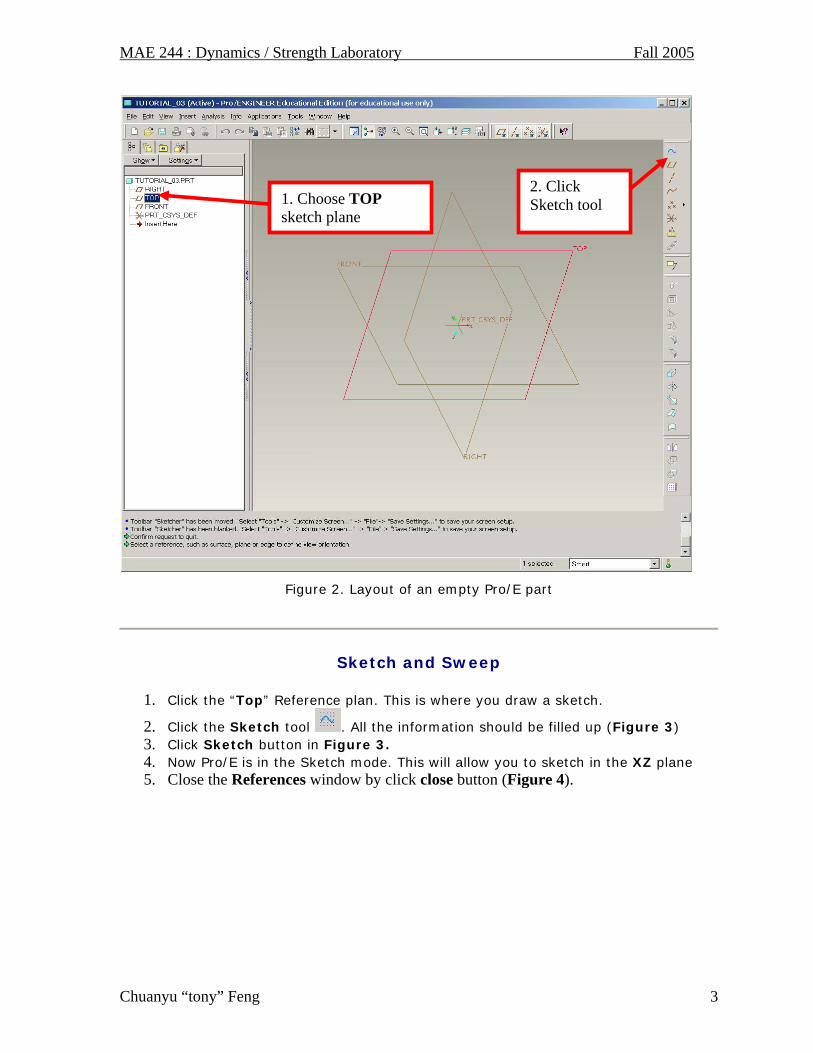
Figure 2. Layout of an empty Pro/E part
Sketch and Sweep
1. Click the “Top” Reference plan. This is where you draw a sketch.
2. Click the Sketch tool . All the information should be filled up (Figure 3) 3. Click Sketch button in Figure 3. 4. Now Pro/E is in the Sketch mode. This will allow you to sketch in the XZ plane 5. Close the References window by click close button (Figure 4).
2. Click Sketch tool 1. Choose TOP
sketch plane

MAE 244 : Dynamics / Strength Laboratory Fall 2005
Chuanyu “tony” Feng 4
Figure 3. Start a sketch: Options
Figure 4. Start a sketch
FYI: Insert and Sketch are the most useful tools. Some of them have a speed button in the Toolbar region.

MAE 244 : Dynamics / Strength Laboratory Fall 2005
Chuanyu “tony” Feng 5
6. You can setup Grid and Snap options by Click menu Sketch Options, check
Grid and Snap to Grid options. Click the Green Check button: (Figure 5) 7. Choose the Line Tool on the right toolbar to make a sketch. To choose the Line
tools, you can directly click the Line Tool in the Sketcher Tools region, or click menu Sketch Line Line.
Figure 5. Sketcher Preferences and Menu Manager
MAE 244 : Dynamics / Strength Laboratory Fall 2005
Chuanyu “tony” Feng 6
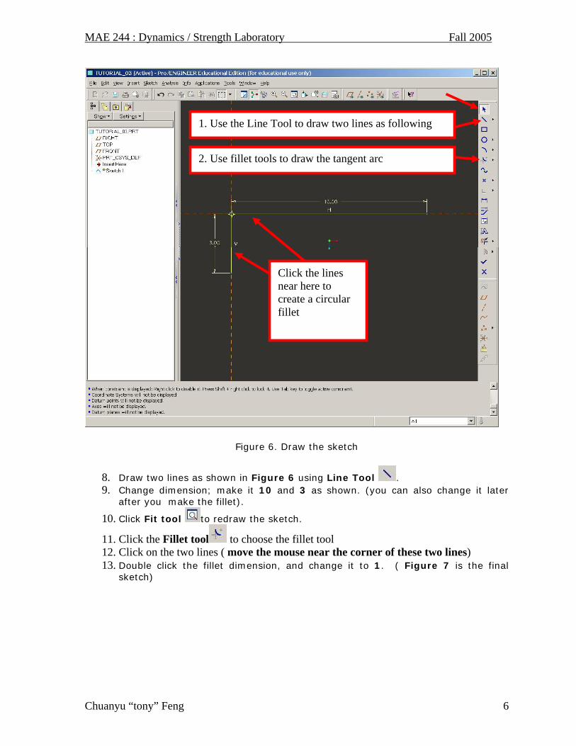
Figure 6. Draw the sketch
8. Draw two lines as shown in Figure 6 using Line Tool . 9. Change dimension; make it 10 and 3 as shown. (you can also change it later
after you make the fillet). 10. Click Fit tool to redraw the sketch.
11. Click the Fillet tool to choose the fillet tool 12. Click on the two lines ( move the mouse near the corner of these two lines) 13. Double click the fillet dimension, and change it to 1. ( Figure 7 is the final
sketch)
Click the lines near here to create a circular fillet
1. Use the Line Tool to draw two lines as following
2. Use fillet tools to draw the tangent arc

MAE 244 : Dynamics / Strength Laboratory Fall 2005
Chuanyu “tony” Feng 7
Figure 7. Final Sketch
14. If you want to change the dimension, double click on the dimension itself, then type in a new dimension.
15. Click Checkmark to finish the sketch. 16. Rotate the sketch by moving the mouse around while Holding middle mouse
button down. 17. Now you have a sketch in the 3D space (Figure 8).
Double click the fillet radius dimension to change it to 1
This will be the final looking of the trajectory sketch used to generate an L-Shaped Rod

MAE 244 : Dynamics / Strength Laboratory Fall 2005
Chuanyu “tony” Feng 8
Figure 8. 3D view of the Sketch
18. Click main menu: Insert Sweep Protrusion,
Figure 9. Sweep Feature

MAE 244 : Dynamics / Strength Laboratory Fall 2005
Chuanyu “tony” Feng 9
19. Choose Select Traj from the Menu Manager
Figure 10. Select Trajectory
20. Holding Ctrl key and Click / select the segment of the sketch one by one. When finished, click Middle mouse button or click OK in the select window.
Figure 11, select the segments
Select one by one while holding Ctrl Key
1 2 3

MAE 244 : Dynamics / Strength Laboratory Fall 2005
Chuanyu “tony” Feng 10
21. Click Middle mouse button or Done in the Menu Manager to finish it (Figure 12) .
Figure 12. click Done
22. Pro/E will move to next step automatically as shown in Figure 13.
Figure 13. Ask for Section
MAE 244 : Dynamics / Strength Laboratory Fall 2005
Chuanyu “tony” Feng 11
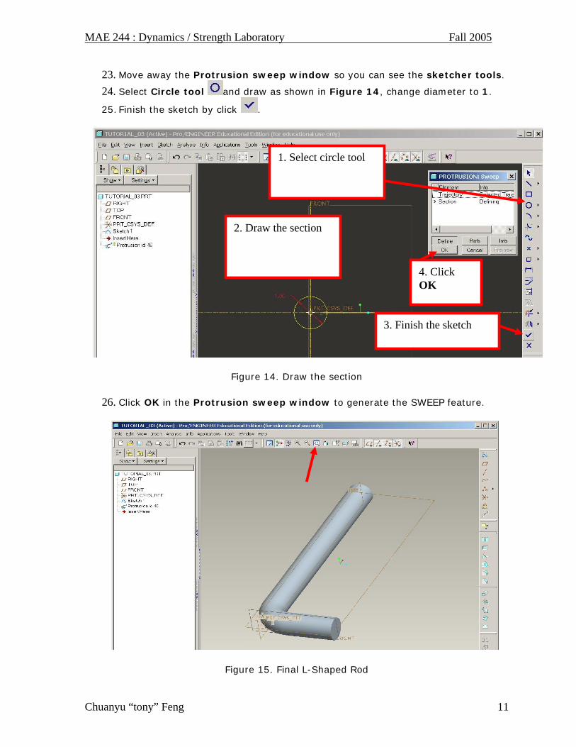
23. Move away the Protrusion sweep window so you can see the sketcher tools. 24. Select Circle tool and draw as shown in Figure 14, change diameter to 1. 25. Finish the sketch by click .
Figure 14. Draw the section
26. Click OK in the Protrusion sweep window to generate the SWEEP feature.
Figure 15. Final L-Shaped Rod
2. Draw the section
1. Select circle tool
3. Finish the sketch
4. Click OK

MAE 244 : Dynamics / Strength Laboratory Fall 2005
Chuanyu “tony” Feng 12
27. Click Fit tool on the tool bar to redraw the L-shaped rod.
28. Save the part by click File Save, or click the disk icon in the tool bar.
FEA using Pro/MECHANICA
Similar to Tutorial 2, you will use integrated Pro/MECHANICA to analyze the L-Shaped Rod. It also consists of 3 steps:
1. Assign material information 2. Setup load and constraint boundary conditions 3. Run the analysis and view the results
Change working mode to Pro/MECHANICA
1. Click menu Applications Mechanica to Enter Pro/MECHANICA working mode. 2. Review the unit information, Click Continue button to proceed (Figure 16)
Figure 16. Unit information

MAE 244 : Dynamics / Strength Laboratory Fall 2005
Chuanyu “tony” Feng 13
3. In pop-up dialog Model Type, select Structure if it is not there (Figure 17). 4. Make sure FEM Mode is UN-checked. This option tells Pro/MECHANICA to
use its own FEA solver. If you check the FEM Mode, it will generate FEA input file for external solvers, such as ANSYS.
5. Click OK to proceed.
Figure 17. Choose the working model type
Create a new material and assign it to the part
1. Show the Mechanica Objects and Actions tool bar on the right chest region.
Figure 18. Right toolchest configuration
1. Put mouse in the right toolchest region, 2. Right click the show up the Configuration menu
3. Make sure Mechanica Objects and Actions are checked. This information is also accessible from Main Menu: Inserts and Analysis

MAE 244 : Dynamics / Strength Laboratory Fall 2005
Chuanyu “tony” Feng 14
2. Select Main menu: Properties Materials 3. Select Al6061 from the Material in Library List.
4. Click add it to the Material in Model List.
Figure 19. Materials
5. Click Assign button, Select Part from the list menu. Pro/E will hide the materials dialog and let you choose the part for the material.
6. Move mouse over the Rod, it will become highlighted. Click on it. 7. Click middle mouse button to confirm the selection. Or Click the OK button
in the Select window. 8. close the materials window 9. Save the file
1. Select Al 6061
2. Click it 3. Click Assign Part
MAE 244 : Dynamics / Strength Laboratory Fall 2005
Chuanyu “tony” Feng 15
Apply Boundary Conditions: Constraints and Loads
Boundary conditions including loads and constraints are applied in this section. You can use the shortcut on the toolbar or use corresponding menu.
Displacement boundary
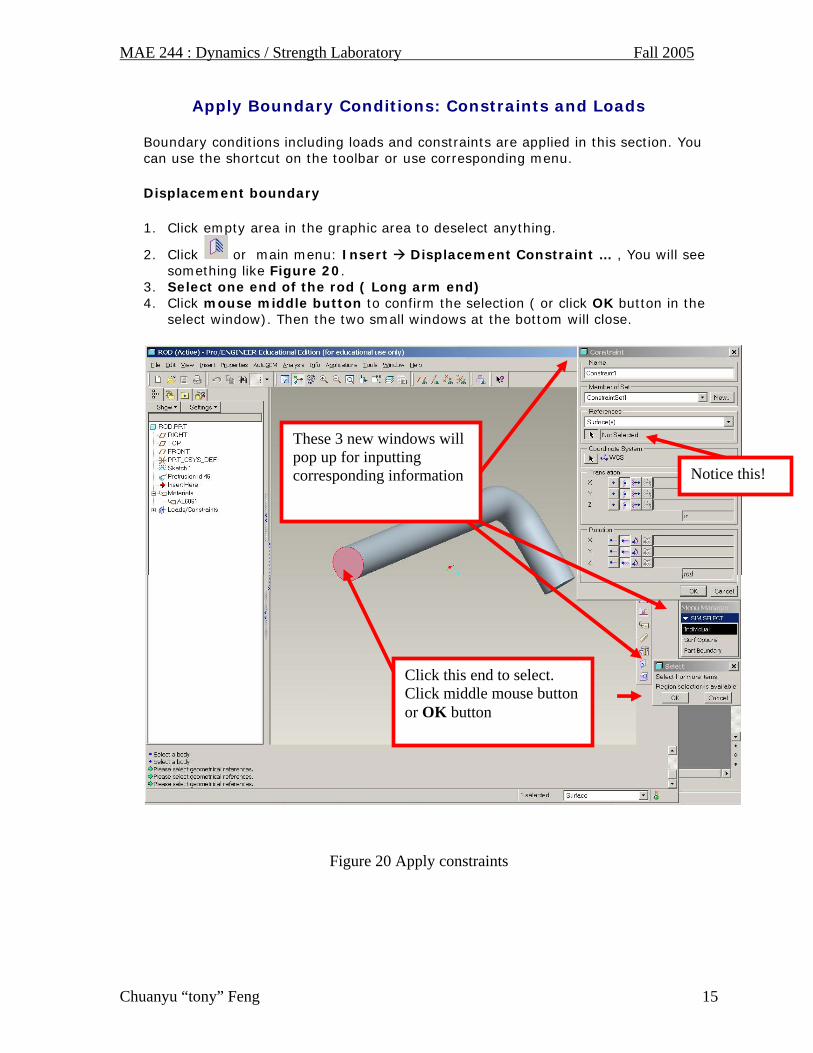
1. Click empty area in the graphic area to deselect anything.
2. Click or main menu: Insert Displacement Constraint … , You will see something like Figure 20.
3. Select one end of the rod ( Long arm end) 4. Click mouse middle button to confirm the selection ( or click OK button in the
select window). Then the two small windows at the bottom will close.
Figure 20 Apply constraints
These 3 new windows will pop up for inputting corresponding information
Click this end to select. Click middle mouse button or OK button
Notice this!

MAE 244 : Dynamics / Strength Laboratory Fall 2005
Chuanyu “tony” Feng 16
5. Input Fixed_End as the name of the constraint, and then click OK button to finis the setup.
Figure 21. Setup constraint
Input a new name
It shows surface selected.

MAE 244 : Dynamics / Strength Laboratory Fall 2005
Chuanyu “tony” Feng 17
Apply Load
6. Rotate the Rod, let the end of the short arm facing you. This time you will use a new method to apply load.
7. Let’s select the surface as shown in Figure 22 first.
8. Then click the or main menu: Insert Force/Moment Load…. 9. Notice that in the Force/Moment Load window, reference has been selected
already. 10. Change the name to Applied_Load, 11. Input the load as shown in Figure 22, x= -75, y = -80, z =100 12. Click Ok to confirm it. 13. Now the Boundary conditions are all setup. We are ready to do the analysis.
Figure 22. Apply Load
1. Select this surface first
2. Click Force/Moment Load …
3. Selection is finished already

MAE 244 : Dynamics / Strength Laboratory Fall 2005
Chuanyu “tony” Feng 18
Figure 23. Rod with Load and displacement boundary condition applied
You can review and edit load and displacement boundary conditions from Model Tree

MAE 244 : Dynamics / Strength Laboratory Fall 2005
Chuanyu “tony” Feng 19
14. Click main menu: Analysis Mechanical Analysis/Studies … 15. It will bring the Analysis and Design Studies window (Figure 24) 16. Click menu File New Static …from Analysis and Design studies window
Figure 24
17. It will bring the Static Analysis Definition window (Figure 25) 18. Make sure Constrains and Loads set are highlighted. 19. Click OK to proceed
Figure 25

MAE 244 : Dynamics / Strength Laboratory Fall 2005
Chuanyu “tony” Feng 20
20. Click menu: Run Start in the Analysis and Design Studies window(Figure 26)
21. Click Yes on the Question window for error detection.
22. Click the Display study status button to see the status of analysis
Figure 26. Run analysis
Display study status
Showing results later
MAE 244 : Dynamics / Strength Laboratory Fall 2005
Chuanyu “tony” Feng 21
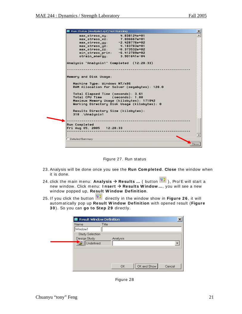
Figure 27. Run status
23. Analysis will be done once you see the Run Completed. Close the window when it is done.
24. click the main menu: Analysis Results … ( button ), Pro/E will start a new window. Click menu: Insert Results Window…, you will see a new window popped up, Result Window Definition.
25. If you click the button directly in the window show in Figure 26, it will automatically pop up Result Window Definition with opened result (Figure 30). So you can go to Step 29 directly.
Figure 28
MAE 244 : Dynamics / Strength Laboratory Fall 2005
Chuanyu “tony” Feng 22
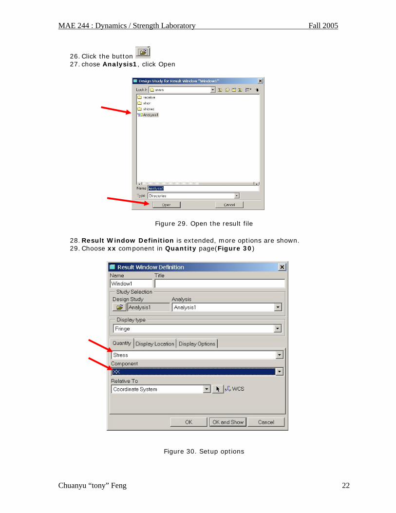
26. Click the button 27. chose Analysis1, click Open
Figure 29. Open the result file
28. Result Window Definition is extended, more options are shown. 29. Choose xx component in Quantity page(Figure 30)
Figure 30. Setup options

MAE 244 : Dynamics / Strength Laboratory Fall 2005
Chuanyu “tony” Feng 23
30. Select Display Options page, setup as shown in the following figure. Make sure Deformed option is un-checked.
31. Click OK and Show to display the stress distribution 32. You can turn off the shade option by click: View Shade ( un-check it)
Figure 31. Setup options

MAE 244 : Dynamics / Strength Laboratory Fall 2005
Chuanyu “tony” Feng 24
33. You can edit the Result window options anytime by select menu: Edit Result
Window (or click ) to edit the result window.
Figure 32. Results
Figure 33. Cutting / Capping Surfs…

MAE 244 : Dynamics / Strength Laboratory Fall 2005
Chuanyu “tony” Feng 25
34. In the Result Surface Definition window, change the type to Capping Surface, select YZ –plane, and the Below location. Uncheck the % box and type in a depth of 8 inches from the origin (elbow of the rod) as shown below. The Click Apply button to see the effect.
Figure 34

MAE 244 : Dynamics / Strength Laboratory Fall 2005
Chuanyu “tony” Feng 26
35. Click the Left view from the Save view list , you can then zoom in to check the detailed stress distribution.
36. Use the technique in Tutorial 02 to save the result as an image file. 37. Alternative method to save results as an image file: Press key: Alt + Print
Screen to copy the full result window into clip board, then use windows program Paint or any other program to save it into a JPEG file. For Paint program, Click Start Programs Accessories Paint. Use Ctrl + V to paste it. Save it as jpeg file. All pictures in these tutorials were obtained through this method.
Figure 35