turcon variseal · zurcon® z80, our uhmwpe based material or zurcon® z48, our thermoplastic...
TRANSCRIPT

Turcon®
Variseal®
your partner for sealing technology
trelleborg sealing solutions

ISO 9001:2008 ISO/TS 16949:2009
Your Partner for Sealing Technology
trelleborg sealing solutions is a major international developer, manufacturer and supplier of seals, bearings and molded components in polymers. We are uniquely placed to offer dedicated design and development from our market-leading product and material portfolio: a one-stop-shop providing the best in elastomer, silicone, thermoplastic, ptfe and composite technologies for applications in aerospace, industrial and automotive industries.
With 50 years of experience, trelleborg sealing solutions engineers support customers with design, prototyping, production, test and installation using state-of-the-art design tools. an international network of over 70 facilities worldwide includes over 20 manu- facturing sites, strategically-positioned research and development centers, including materials and development laboratories and locations specializing in design and applications.
Developing and formulating materials in-house, we utilize the resource of our material database, including over 2,000
proprietary compounds and a range of unique products.trelleborg sealing solutions fulfills challenging service requirements, supplying standard parts in volume or a single custom-manufactured component, through our integrated logistical support, which effectively delivers over 40,000 sealing products to customers worldwide.
facilities are certified to iso 9001:2008 and iso/ts 16949:2009. trelleborg sealing solutions is backed by the experience and resources of trelleborg group, one of the world’s foremost experts in polymer technology.
the information in this brochure is intended to be for general reference purposes only and is not intended to be a specific recommendation for any individual application.
the application limits for pressure, temperature, speed and media given are maximum values determined in laboratory conditions. in application, due to the interaction of operating
parameters, maximum values may not be achieved. it is vital therefore, that customers satisfy themselves as to the suitability of product and material for each of their individual
applications. any reliance on information is therefore at the user‘s own risk. in no event will trelleborg sealing solutions be liable for any loss, damage, claim or expense directly
or indirectly arising or resulting from the use of any information provided in this brochure. While every effort is made to ensure the accuracy of information contained herewith,
trelleborg sealing solutions cannot warrant the accuracy or completeness of information.
To obtain the best recommendation for a specific application, please contact your local Trelleborg Sealing Solutions marketing company.
this edition supersedes all previous brochures. this brochure or any part of it may not be reproduced without permission.
® all trademarks are the property of trelleborg group. the turquoise color is a registered trademark of trelleborg group. © 2015, trelleborg group. all rights reserved.
2 ˙ trelleborg sealing solutions lastest information available at www.tss.trelleborg.com ˙ edition august 2016
TRELLEBORG SEALING SOLUTIONS • 3Latest information available at www.tss.trelleborg.com • Edition August 2016
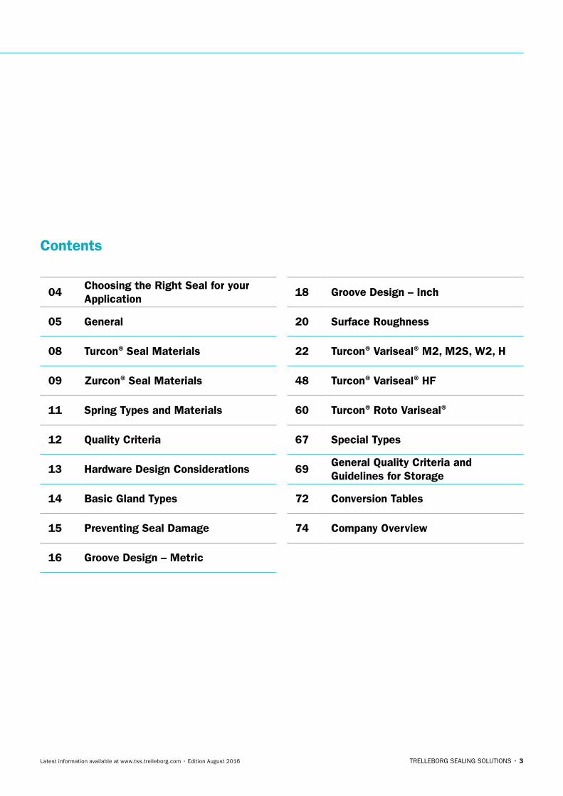
Contents
04Choosing the Right Seal for your Application
05 General
08 Turcon® Seal Materials
09 Zurcon® Seal Materials
11 Spring Types and Materials
12 Quality Criteria
13 Hardware Design Considerations
14 Basic Gland Types
15 Preventing Seal Damage
16 Groove Design – Metric
18 Groove Design – Inch
20 Surface Roughness
22 Turcon® Variseal® M2, M2S, W2, H
48 Turcon® Variseal® HF
60 Turcon® Roto Variseal®
67 Special Types
69General Quality Criteria and Guidelines for Storage
72 Conversion Tables
74 Company Overview

4 • TRELLEBORG SEALING SOLUTIONS Latest information available at www.tss.trelleborg.com • Edition August 2016
TURCON® VARISEAL® · Choosing the Right Seal for your Appplication
� Choosing the Right Seal for your ApplicationTurcon® Variseal® offers major benefits in the design of components such as cylinders. These include:
- Excellent leakage control
- High resistance to wear
- High resistance to extrusion into gaps
- Withstanding aggressive and abrasive process media
- Very good temperature capabilities
- Low friction
- Compact form
Turcon® Variseal® is available in a range of geometries and designs that allow the optimum profile to be selected for each application. They can be produced from a wide range of Turcon® materials, our proprietary PTFE based compounds. These are specially formulated for sealing elements and offer superior characteristics specifically matched to the demands of our customers.
When required, Variseal® can also be manufactured from Zurcon® Z80, our UHMWPE based material or Zurcon® Z48, our Thermoplastic Elastomer material.
To choose the best Turcon® Variseal® or your application, you must first decide the functional parameters. Table 1 and Table 2 on page 6 and Table 3 on page 7 can then be used to make an initial selection of seals and materials. These tables give details of where further details can be found in the catalog.
It is also important to consider the quality of the mating surface, which has a significant effect on the function and service life of the sealing system. Guidelines on these are given on page 20 and page 21.
If help is required in specification of a seal then contact Trelleborg Sealing Solutions. To find your local marketing company go to www.tss.trelleborg.com.
TRELLEBORG SEALING SOLUTIONS • 5Latest information available at www.tss.trelleborg.com • Edition August 2016
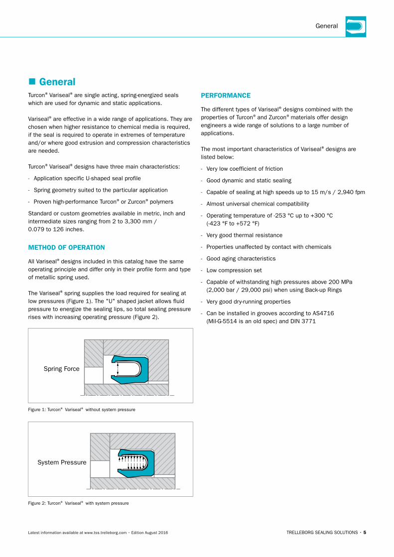
General
� GeneralTurcon® Variseal® are single acting, spring-energized seals which are used for dynamic and static applications.
Variseal® are effective in a wide range of applications. They are chosen when higher resistance to chemical media is required, if the seal is required to operate in extremes of temperature and/or where good extrusion and compression characteristics are needed.
Turcon® Variseal® designs have three main characteristics:
- Application specific U-shaped seal profile
- Spring geometry suited to the particular application
- Proven high-performance Turcon® or Zurcon® polymers
Standard or custom geometries available in metric, inch and intermediate sizes ranging from 2 to 3,300 mm / 0.079 to 126 inches.
MeTHOD OF OPeRATIOn
All Variseal® designs included in this catalog have the same operating principle and differ only in their profile form and type of metallic spring used.
The Variseal® spring supplies the load required for sealing at low pressures (Figure 1). The "U" shaped jacket allows fluid pressure to energize the sealing lips, so total sealing pressure rises with increasing operating pressure (Figure 2).
Spring Force
Figure 1: Turcon® Variseal® without system pressure
System Pressure
Figure 2: Turcon® Variseal® with system pressure
PeRFORMAnCe
The different types of Variseal® designs combined with the properties of Turcon® and Zurcon® materials offer design engineers a wide range of solutions to a large number of applications.
The most important characteristics of Variseal® designs are listed below:
- Very low coefficient of friction
- Good dynamic and static sealing
- Capable of sealing at high speeds up to 15 m/s / 2,940 fpm
- Almost universal chemical compatibility
- Operating temperature of -253 °C up to +300 °C (-423 °F to +572 °F)
- Very good thermal resistance
- Properties unaffected by contact with chemicals
- Good aging characteristics
- Low compression set
- Capable of withstanding high pressures above 200 MPa (2,000 bar / 29,000 psi) when using Back-up Rings
- Very good dry-running properties
- Can be installed in grooves according to AS4716 (Mil-G-5514 is an old spec) and DIN 3771

6 • TRELLEBORG SEALING SOLUTIONS Latest information available at www.tss.trelleborg.com • Edition August 2016
TURCON® VARISEAL® · General
Table 1: Turcon® Variseal® Selection Table
Seal Application Technical Data
Type Page
Type of Ap plication
Maximum PressureWorking Temp.
Maximum SpeedS
tati
c
Rec
ipro
cati
ng
Rot
ary Dynamic
MPa (bar, psi)
Static MPa
(bar, psi)°C / (°F)
Rec
ipro
cati
ng
m/
s (f
pm)
Rot
atin
g
m/
s (f
pm)
M2 page
22C A B
20 (200, 2900)
40 (400, 5800)
-70 to +300 (-94 to +572)
15 (2940)
1.27 (250)
M2Spage 23
C A C20
(200, 2900)40
(400, 5800)-70 to +300
(-94 to +572)15
(2940)1.27 (250)
W2page 24
C A B20
(200, 2900)40
(400, 5800)-70 to +300
(-94 to +572)15
(2940)1.27 (250)
Hpage 25
A B C20
(200, 2900)40
(400, 5800)-100 to +200
(-148 to +392)5
(985)0.10 (18)
HFpage 46
A - C n/a60
(600, 8702)-150 to +200
(-238 to +392)n/a n/a
Rotopage 60
B B A20
(200, 2900)25
(250, 3626)-70 to +300
(-94 to +572)15
(2940)2.00 (360)
Properties: A Excellent B Good C Satisfactory
Table 2: Application Guide
Contact medium or operating condition
Static or slightly Dynamic Reciprocating Rotating
Air, Gas Turcon® T05 Turcon® T24 Turcon® T24
Water, Steam Turcon® T05 Turcon® T40 Turcon® T40
Oil, Crude oil Turcon® T05 Turcon® T40 Turcon® T40
General chemical Turcon® T05 Turcon® T40 Turcon® T40
Petrochemicals Turcon® T05 Turcon® T40 Turcon® T40
Food, Drugs Turcon® MF1 Zurcon® Z801) Turcon® MF6
Vacuum Turcon® T01 Turcon® T05 Turcon® T05
1) Maximum operating temperature +93 °C (+200 °F). In a pressure-free state, sterilization is possible for a short period at higher temperature

TRELLEBORG SEALING SOLUTIONS • 7Latest information available at www.tss.trelleborg.com • Edition August 2016
General
Table 3: Turcon® and Zurcon® Material Selection Guide
Material Code
Material DescriptionTemperature
Range°C (°F)
Chemical Compatibility
Radiation Resistance
T01 / MF1Premium grade virgin PTFE for static, slow dynamic or light duty applications. MF1 for food contact service requiring a FDA compliant material. Color: white
-253 to +260 (-423 to +500)
A7 x 102 Gray
(7 x 10⁴
Rads)
T05Premium grade modified PTFE. Light duty material with greater wear resistance than Turcon T01. Reciprocating and slow rotary applications. Color: turquoise
-200 to +260 (-328 to +500)
A7 x 102 Gray
(7 x 10⁴
Rads)
T07Proprietary polymer-reinforced compound for long wear life in difficult combinations of pressure and temperature. Color: black
-60 to +300 (-76 to +572)
A7 x 102 Gray
(7 x 10⁴
Rads)
T12Use where poor lubrication is a problem, good performance in valve applications. Color: black
-60 to +300 (-76 to +572)
A7 x 102 Gray
(7 x 10⁴ Rads)
T24
High-grade formulation of virgin polytetrafluoroethylene (PTFE) based material compounded with carbon additive. Recommen-ded for dynamic applications, in particular dry-running air and gas). Color: black
-60 to +300 (-76 to +572)
A7 x 102 Gray
(7 x 10⁴
Rads)
T25
High-grade formulation of virgin polytetrafluoroethylene (PTFE) based material compounded with glass fibers and lubricant additives. Excellent wear and low friction characteristics for lubricated rotary applications. Color: black / grey
-60 to +300 (-76 to +572)
A7 x 102 Gray
(7 x 10⁴
Rads)
T40 / MF4
High-grade formulation of virgin polytetrafluoroethylene (PTFE)based material compounded with carbon fiber additive. Excel-lent wear and low friction characteristics. Suited to recipro-cating and rotary applications. Suitable for use in media with poor lubricating properties and for dry-running situations. MF4, a specialized grade of Turcon® T40 compound, available with certification of FDA compliance. Color: black / grey
-60 to +300 (-76 to +572)
A7 x 102 Gray
(7 x 10⁴
Rads)
M79
High grade formulation of virgin polytetrafluoroethylene (PTFE)based material compounded with an aromatic polymer and lubricant. Especially suited for low pressure rotary applications and running against soft surfaces. Color: black / grey
-100 to +300 (-148 to +572)
A7 x 102 Gray
(7 x 10⁴
Rads)
MF6
High grade formulation of virgin polytetrafluoroethylene (PTFE) based material compounded with an aromatic polymer. Espe-cially suited for low pressure rotary applications and running against soft surfaces. MF6 for food contact service requiring a FDA compliant material. Color: beige
-60 to +260 (-76 to +500) A
7 x 10² Gray (7 x 10⁴ Rads)
Z48TPE (thermoplastic elastomer) for tight sealing with long wear life in applications without high temperatures or corrosive che-micals. Color: black
-62 to +135 (-80 to +275)
C
1.5 x 10⁵ Gray
(1.5 x 10⁷
Rads)
Z80UHMW Polyethylene. Excellent wear and abrasion resistance. Very good lubricity in water based media. Color: translucent white
-253 to +93 (-423 to +200)
B1 x 105 Gray
(1 x 10⁷
Rads)
For temps above 500 °F (260 °C), please reference the Society of Plastics Industry’s Safe Handling Guide.

8 • TRELLEBORG SEALING SOLUTIONS Latest information available at www.tss.trelleborg.com • Edition August 2016
TURCON® VARISEAL® · Turcon® Seal Materials
� Turcon® Seal MaterialsHigh Surface SpeedsThe mechanical properties of Turcon® materials mean they are excellent in dynamic applications, even under extreme loads.
Turcon® seals offer higher operational reliability than elastomer seals in dynamic situations, especially in dry starting or operating conditions, as they do not suffer from adhesion or heat generation. When the application is lubricated, seal life will be extended further.
Wear ResistanceWear resistance is dependent upon material fillers which influence the Turcon® material‘s mechanical and physical properties. Fillers in Turcon® include graphite, carbon, carbon fiber, glass fiber, molybdenum disulphide and other polymers. They can give increased resilience, improved wear resistance, reduced thermal expansion and extremely high resistance to abrasive wear.
AgingTurcon® materials remain unchanged over extended periods. They are practically non-aging and do not become brittle or degrade, even when subject to severe weathering from heat, light, water or salt spray.
RadiationTurcon® materials exhibit a low resistance to electron and gamma radiation and are not recommended for use in applications where the accumulated radiation doses exceed 7 x 10² Gy (7 x 10⁴ rad). For applications, subject to high radiation doses, special fluoropolymers such as ETFE and PCTFE or Zurcon® materials should be selected.
Other PropertiesSome Turcon® materials have outstanding electrical properties, such as a low dielectric constant or a very high electric strength, even at elevated temperatures.
Physiologically safe Turcon® materials are available which meet the requirements of the German Federal Health Authority (BGA) and the FDA Regulation (Food and Drug Administration) No. 21 CFR, Part 177.
The water absorption of Turcon® materials is < 0.01 %.
Turcon® materials are high performance thermoplastics specifically developed for sealing applications. They are based on premium-grade PTFE fluoropolymer resins, with the properties of each compound achieved by the addition of fillers and special processing techniques.
Turcon® materials offer the following benefits:
Low Coefficient of FrictionFriction is dependent on pressure, contact surface area, speed and lubrication. Turcon® materials have very good friction characteristics. For example, a coefficient of friction on steel mating surfaces of 0.04 can be achieved under lubricated and hydrodynamic conditions.Turcon® materials do not adhere to their mating surfaces and show only a slight difference between static and dynamic friction, thus eliminating the danger of the stick-slip effect in dynamic applications.
Chemical CompatibilityTurcon® materials are stable in all hydraulic fluids. Seal materials should be chosen to suit the lubricating properties of hydraulic media and the wear properties of seal and mating surfaces.
There is only a slight change in chemical properties of Turcon®
materials, compared to chemically inert virgin PTFE, dependent on the type of filler material added.
Temperature RangeTurcon® materials can be used at temperatures between -253 °C and +300 °C (-423 °F and +572 °F). The limits for low temperatures are dependent on seal design and the thermal contraction of the material. Special designs are available for sealing cryogenic fluids at temperatures below -200 °C (-328 °F).
General service temperature is limited to +300 °C (+572 °F). At temperatures above this, the seal materials begin to lose their strength and are subject to plastic deformation.
For temperatures above +260 °C (+500 °F), please reference the Society of the Plastics Industry‘s Safe Handling Guide.
Temperature CyclingCyclical temperature fluctuations do not change the properties of Turcon® materials.

TRELLEBORG SEALING SOLUTIONS • 9Latest information available at www.tss.trelleborg.com • Edition August 2016
Zurcon® Seal Materials
� Zurcon® Seal MaterialsWear ResistanceThe abrasive wear resistance of Zurcon® Z80 is 5 to 10 times higher than that of PTFE based materials. It is therefore recommended in applications where seals are in contact with abrasive media such as paints, adhesives, salts, sludges, etc.
Zurcon® Z80 is also highly resistant to extrusion at high pressures.
Radiation ResistanceThe radiation resistance of Zurcon® Z80 is significantly higher than that of PTFE based materials, maintaining good mechanical properties at radiation dosages of up to 100 kGy.
Applications in the food and pharmaceutical industriesZurcon® Z80 is physiologically safe and can be used for sealing in food and pharmaceutical processing. It has no odor or taste and is suitable for food contact.
The material complies with the recommendations of the BGA and FDA Regulation 21 CFR, Part 177.
Zurcon® Z80Zurcon® Z80 is a virgin Ultra High Molecular Weight Polyethylene, or UHMWPE. Because the water absorption of Zurcon® Z80 is zero, it is ideal for water service. Its abrasion resistance is five to ten times higher than PTFE, making it the material of choice in abrasive environments. As it is physiologically safe, it is also suitable for use in food and pharmaceutical processing.
The main characteristics of Zurcon® Z80 are:
Low FrictionThe dry friction coefficient of Zurcon® Z80 is lower than most other materials though higher than many filled PTFE materials. Zurcon® Z80 forms a self-lubricating, non-stick surface.
Chemical CompatibilityZurcon® Z80 is stable in all hydraulic fluids. It has a high resistance to acids, bases and aggressive media. The material has limited resistance to aromatic and halogenated hydrocarbons.
Water ServiceZurcon® Z80 is water repellent and does not swell in water. Its self-lubricating properties in water-based media are excellent, giving it significant advantage over many other materials including PTFE-based ones. This combined with its high strength and wear resistance means it has a long service life in aqueous solutions.
Temperature RangeZurcon® Z80 has a maximum continuous operating temperature of +93 °C (+200 °F). Above this temperature its wear resistance and strength begins to decrease. In low-pressure applications it can be used at temperatures of +120 °C (+248 °F) for short periods and can be sterilized briefly at even higher temperatures. Its lowest operating temperature is -200 °C (-328 °F).

10 • TRELLEBORG SEALING SOLUTIONS Latest information available at www.tss.trelleborg.com • Edition August 2016
TURCON® VARISEAL® · Zurcon® Seal Materials
Zurcon® Z48 (TPe)Thermoplastic elastomer (TPE) materials combine several of the most desirable features of high performance elastomers and flexible plastics. They have exceptional toughness and resilience, with high resistance to creep, impact and fatigue. The premium grades used in the Variseal® are fully machinable as well as injection moldable and have the following notable properties.
Sealing ability TPE conforms well to mating surfaces and, when energized by a spring load, has very good resilience making it an excellent sealing material with very low leakage rates.
Friction The coefficient of friction of a typical TPE material ranges from 0.30 to 0.60, depending on the mating surface finish and other service conditions. It is not normally recommended for dry service except at very slow speeds due to concerns about heat generation leading to material degradation. In lubricated service conditions the speed rating is greatly increased and TPE materials may then be considered for use in moderate to high speed reciprocating applications, or in slow to moderate speed rotary service.
Wear and extrusion resistanceTPE blends have excellent wear resistance in well lubricated service where heat generation is kept to a minimum. It is especially long lasting in low to moderate speeds in reciprocating service at low or high pressures. TPE is also noted for its excellent extrusion resistance in high pressure applications up to 68.9 MPa (10,000 psi).
Temperature range TPE materials exhibit excellent physical properties over a broad temperature range. Various grades are flexible to -62 °C (-80 °F), and retain good physical properties at temperatures to +135 °C (+275 °F). At temperatures above +135 °C (+275 °F), however, TPE is only recommended in short term service because it is subject to heat aging and embrittlement.
CompatibilityThermoplastic elastomers resist deterioration from many industrial chemicals, oils and solvents. They are resistant to swelling in oils and aliphatic and aromatic hydrocarbons at moderate temperatures. TPE is limited in its compatibility with hot water applications. For example, in long-term service sealing water at +71 °C (+160 °F), TPE loses much of its resilience and experiences a significant drop in tensile strength.

TRELLEBORG SEALING SOLUTIONS • 11Latest information available at www.tss.trelleborg.com • Edition August 2016
Spring Types and Materials
� Spring Types and MaterialsHelical SpringThe Helical spring, used in Variseal® H and Variseal® HF, is made from a flat strip formed into a helical coil spring. It has a much higher unit load and a shorter deflection range than the other spring types. Therefore, it is best suited to static or slow dynamic applications, where friction and wear are not the key issues. Variseal® H and Variseal® HF are the best choices for vacuum, gas and low temperature applications.
Slantcoil® SpringThe Slantcoil® spring used in Variseal® W2 consists of round wire formed into slanted coils and has a relatively constant load over a wide deflection range. This allows accurate control of friction during the working life of the seal. Its unique design makes it almost impossible to damage the spring by excessive deformation of the seal.
Percentage deflection from free height (%)
Spr
ing
Forc
e (F
)
The load point wheninstalled in the gland
Helical spring
Slantcoil® spring
V-spring
0 10 20 30 40 50 60
Slantcoil® spring
Helical spring
V-spring
Figure 3: Comparison of load curves for the three spring types
A metal spring is incorporated into Turcon® Variseal® to provide elasticity to the seal. This makes the seal permanently elastic, despite changes in operating temperature, pressure or chemicals processed. Each of the three spring types used in Variseal® has unique properties that give them their performance characteristics. The two most important properties of the spring, besides the corrosion resistance of the metal, are load value and deflection range. The spring load affects sealing ability, friction and the wear rate of the seal. The deflection range determines the ability of the Variseal®
designs to take up wear and compensate for variations in gland dimensions.
V-SpringV-Spring is the standard spring type for Variseal® M2, Variseal® M2S and Roto Variseal®. It operates as a set of "cantilever beams", extending from an arc at the bottom of the spring. The shape of the spring causes the load to be focused on the front edge of the sealing lip, giving the seal a positive wiping action. The V-Spring has a moderate load and deflection range.

12 • TRELLEBORG SEALING SOLUTIONS Latest information available at www.tss.trelleborg.com • Edition August 2016
TURCON® VARISEAL® · Quality Criteria
Spring MaterialsThe standard spring material for Turcon® Variseal® is stainless steel (spring code S). Two further materials are available for the specific applications, as detailed in the table below.
Table 4: Spring Materials Selection Guide
Media Spring materials Spring order code
For General use e.g. Oil Grease Air Water, steam Solvents Food, drugs Gas
Stainless steel DIN Mat No. 1.4310/1.4319
AISI 301/302UNS 30100
S (Standard
spring material)
For use in corrosive media e.g. Acids Caustics Seawater
Hastelloy® C-276 DIN Mat No. 2.4819
UNS N10276H
For petrochemical use e.g. Crude oil Sour gas
elgiloy® 1) DIN Mat No. 2.4711
UNSR30003E
� Quality CriteriaSeals and bearings manufactured by Trelleborg Sealing Solutions are continuously monitored according to strict quality standards from material supply to delivery of finished parts.
Production plants are certified to international standards such as EN ISO 9001, covering quality control and management of purchasing, production and marketing functions.
All testing of materials and products is performed in accordance with accepted test standards and specifications. Our sealing materials are produced free of chlorofluorinated hydrocarbons and carcinogenic elements.
The tenth digit of our Trelleborg Sealing Solutions part number defines the quality characteristics of the part. A hyphen indicates compliance with standard quality criteria outlined in this catalog. Customer-specific requirements are indicated by a different symbol. Customers who require special quality criteria should contact their local Trelleborg Sealing Solutions marketing company for assistance.
® Hastelloy is a registered trademark of Haynes International, Inc. ® Elgiloy is a registered trademark of the Elgiloy Specialty Metals
Alternative brand may be used. 1) NACE-approval

TRELLEBORG SEALING SOLUTIONS • 13Latest information available at www.tss.trelleborg.com • Edition August 2016
Hardware Design Considerations
� Hardware Design ConsiderationsThe best way to obtain optimum Variseal® performance is to plan ahead - during the design phase of your product. The initial phase should bring into alignment the three factors having the greatest impact on seal performance - the hardware design, the service conditions, and the seal design.
Design issues such as gland style, mating surface hardness and surface finish, and dynamic alignment should be reviewed and adjusted to work with the intended service conditions and to suit the selected seal design. The information in this section is primarily intended as a guide for the design of new hardware, however, it is completely applicable to the task of reviewing or modifying existing hardware to improve seal performance.
A primary goal in selecting a basic gland style is to be able to install the seals without damaging them. The first half of this Section describes the various gland types and installation procedures.
Once the issue of seal installation has been addressed, the goal of hardware design is then to improve seal performance in terms of wear life, leakage rate, friction, and so on.
Basic Gland StylesThere are three basic gland styles to be considered - split, stepped, and solid (see Figure 4). The gland required for a radial Variseal® is similar to an O-Ring gland with one major difference - an O-Ring gland has a typically solid (one piece) construction with a full gland wall on each side. Since the Variseal® is made from polymers, which do not stretch like elastomers, installation in such glands can be difficult - or in many cases impossible. To install the Variseal® easily requires either the split gland or the stepped gland. The solid groove is sometimes used, but only when no other option exists and then only with certain diameter restrictions described later in the Groove Design section.
When retrofitting an existing solid gland for which the hardware cannot be modified, the solution might involve a special seal design or installation tools. Our engineering and technical support personnel are always available to assist you with these situations. To discuss your application, please contact your local Variseal® representative.
The basic gland styles shown above are described in further detail on the following pages.
Stepped Piston
Stepped HousingSplit Housing
Split Piston Solid Piston
Solid Housing
Figure 4: Basic Radial Gland Styles

14 • TRELLEBORG SEALING SOLUTIONS Latest information available at www.tss.trelleborg.com • Edition August 2016
TURCON® VARISEAL® · Basic Gland Types
� Basic Gland TypesSplit GlandThe best way to obtain optimum Variseal® performance is to plan a Split gland. A split gland designates hardware that is separated or “split” into two pieces to allow assembly without deforming the seal. The split gland minimizes potential damage to the seal. Its advantages include:
- No stretching of the seal
- Repeated installation without damage
- No special installation tools
The disadvantage is that a second piece such as an end plate is required to retain the seal. This might also involve a third piece such as a bolt to secure the end plate.
Stepped GlandsA stepped gland has a small “step” or ledge, which retains the seal. The step height is small, so that the seal can be pushed past it easily. See the Groove Design section for recommended step heights. In most cases, no special tooling or installation procedures are required.
The stepped gland has the advantage of being a simpler configuration (with fewer pieces than the split gland) while maintaining relative ease of assembly. The stepped gland is an excellent configuration for piston seal applications.
Solid GlandsBecause the Variseal® does not stretch like an elastomeric O-ring, it is difficult to install in a solid radial groove. This gland is not recommended for new designs, but is often encountered when retrofitting existing glands. It can be used in those cases where the ratio of seal diameter to seal cross-section is large enough.
Face Seal GlandsFace seal glands for the Variseal® are typically the same as O-ring glands, with no problems installing the seal. One advantage of the Variseal® in face seal applications is that it does not require a full gland wall on the pressure side of the seal.
Figure 5: Split or “two piece” Glands
Figure 6: Stepped Glands
Figure 7: Solid or “one piece” Glands
Figure 8: Face Seal Glands
TRELLEBORG SEALING SOLUTIONS • 15Latest information available at www.tss.trelleborg.com • Edition August 2016
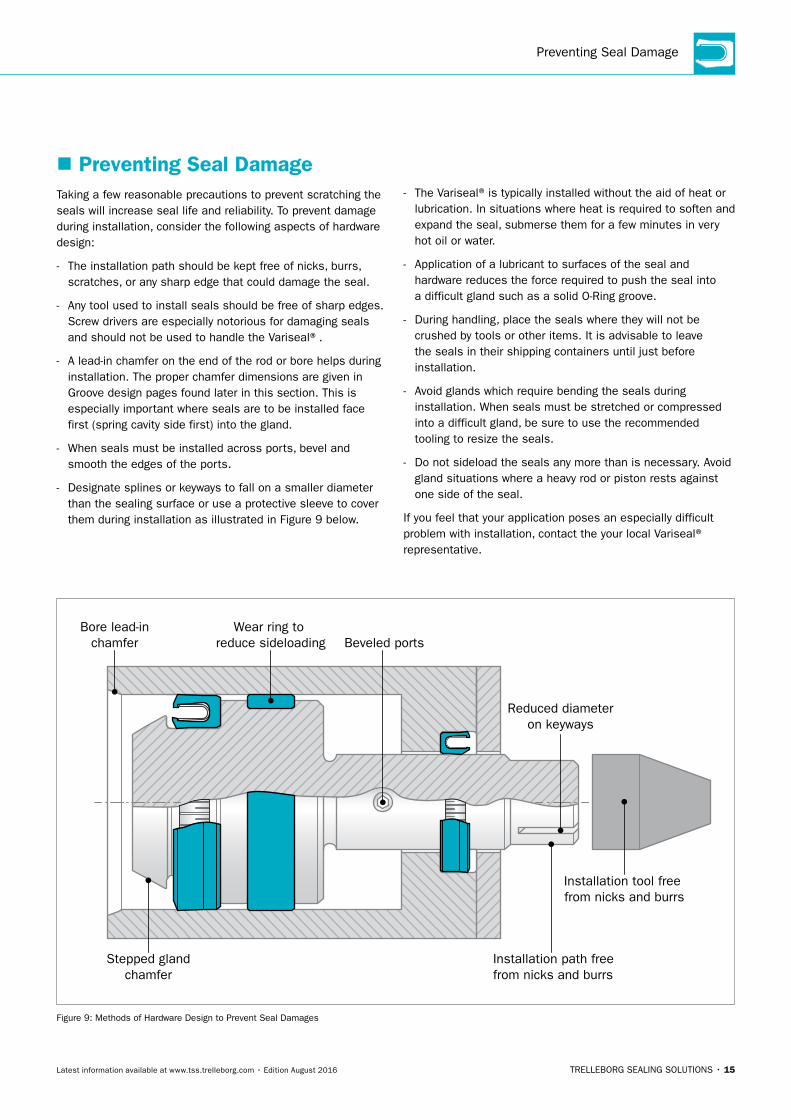
Preventing Seal Damage
� Preventing Seal DamageTaking a few reasonable precautions to prevent scratching the seals will increase seal life and reliability. To prevent damage during installation, consider the following aspects of hardware design:
- The installation path should be kept free of nicks, burrs, scratches, or any sharp edge that could damage the seal.
- Any tool used to install seals should be free of sharp edges. Screw drivers are especially notorious for damaging seals and should not be used to handle the Variseal®.
- A lead-in chamfer on the end of the rod or bore helps during installation. The proper chamfer dimensions are given in Groove design pages found later in this section. This is especially important where seals are to be installed face first (spring cavity side first) into the gland.
- When seals must be installed across ports, bevel and smooth the edges of the ports.
- Designate splines or keyways to fall on a smaller diameter than the sealing surface or use a protective sleeve to cover them during installation as illustrated in Figure 9 below.
- The Variseal® is typically installed without the aid of heat or lubrication. In situations where heat is required to soften and expand the seal, submerse them for a few minutes in very hot oil or water.
- Application of a lubricant to surfaces of the seal and hardware reduces the force required to push the seal into a difficult gland such as a solid O-Ring groove.
- During handling, place the seals where they will not be crushed by tools or other items. It is advisable to leave the seals in their shipping containers until just before installation.
- Avoid glands which require bending the seals during installation. When seals must be stretched or compressed into a difficult gland, be sure to use the recommended tooling to resize the seals.
- Do not sideload the seals any more than is necessary. Avoid gland situations where a heavy rod or piston rests against one side of the seal.
If you feel that your application poses an especially difficult problem with installation, contact the your local Variseal® representative.
Stepped glandchamfer
Wear ring to reduce sideloading
Bore lead-inchamfer Beveled ports
Installation path freefrom nicks and burrs
Installation tool free from nicks and burrs
Reduced diameteron keyways
Figure 9: Methods of Hardware Design to Prevent Seal Damages

16 • TRELLEBORG SEALING SOLUTIONS Latest information available at www.tss.trelleborg.com • Edition August 2016
TURCON® VARISEAL® · Groove Design – Metric
� Groove Design – Metric
Split Housing
Split Piston Stepped Piston Solid Piston
Stepped Housing Solid Housing
r1
30°
30°
A C
A HC
d N m
in.
D1 m
in.
DN
min
.
D2 m
in.
30°
30°
30°
30°
r2
r2
r1
r1
d 1 m
in.
EE
H
d 2 m
in.
r1 r1
r1
Figure 10: Variseal Groove Configurations
Installation lead-in chamfers and steps to include blend radii and are to be polished.
Table 5: Dimensions for Groove Designs – Metric
Series
Rod / Piston Groove Dimensions
A Chamfer
r1 Maximum
Radius
C Minimum Chamfer
r2 Maximum
Radius
e Minimum
Step Height
H Minimum Chamfer
000 0.25 / 0.38 0.25 0.70 0.13 0.40 1.20
100 0.38 / 0.51 0.38 1.10 0.13 0.60 1.50
200 0.38 / 0.51 0.38 1.25 0.18 0.70 2.50
300 0.51 / 0.69 0.38 1.40 0.25 0.80 4.50
400 0.51 / 0.69 0.51 1.60 0.25 0.90 6.00
500 0.76 / 1.02 0.51 2.60 0.38 1.50 11.00

TRELLEBORG SEALING SOLUTIONS • 17Latest information available at www.tss.trelleborg.com • Edition August 2016
Groove Design – Metric
Table 6: Groove Design for Rod – Metric
Series
Rod Diameter Recommendations
Split GrooveØ dn
MinimumType
M2,M2S, W2, H
Stepped GrooveØ d1
MinimumType
M2, M2S, W2, H
Solid GrooveØ d2
Minimum
Type M2, M2S
Type W2
Type H
000 3.00 20.00 31.75 25.40 25.40
100 6.00 30.00 69.85 63.50 63.50
200 10.00 35.00 111.13 107.95 107.95
300 20.00 40.00 298.45 228.60 228.60
400 35.00 45.00 495.30 400.05 400.05
500 80.00 80.00 762.00 635.00 635.00
Table 7: Groove Design for Piston – Metric
Series
Piston Diameter Recommendations
Split GrooveØ Dn
MinimumType
M2, M2S, W2, H
Stepped GrooveØ D1
MinimumType
M2, M2S, W2, H
Solid Groove Ø D2
Minimum
Type M2, M2S
Type W2
Type H
000 6.00 11.50 34.93 19.05 19.05
100 10.00 17.50 50.80 28.58 28.58
200 16.00 20.00 69.85 44.45 44.45
300 28.00 28.00 104.78 60.33 60.33
400 45.00 45.00 139.70 95.25 95.25
500 100.00 100.00 254.00 203.20 203.20

18 • TRELLEBORG SEALING SOLUTIONS Latest information available at www.tss.trelleborg.com • Edition August 2016
TURCON® VARISEAL® · Groove Design – Inch
� Groove Design – Inch
Split Housing
Split Piston Stepped Piston Solid Piston
Stepped Housing Solid Housing
r1
30°
30°
A C
A HC
d N m
in.
D1 m
in.
DN
min
.
D2 m
in.
30°
30°
30°
30°
r2
r2
r1
r1
d 1 m
in.
EE
H
d 2 m
in.
r1 r1
r1
Figure 11: Variseal Groove Configurations
Installation lead-in chamfers and steps to include blend radii and are to be polished.
Table 8: Dimensions for Groove Designs – Inch
Series
Rod / Piston Groove Dimensions
A Chamfer
r1 Maximum
Radius
C Minimum Chamfer
r2 Maximum
Radius
e Minimum
Step Height
H Minimum Chamfer
000 0.010 / 0.015 0.010 0.028 0.005 0.016 0.047
100 0.015 / 0.020 0.015 0.043 0.005 0.024 0.059
200 0.015 / 0.020 0.015 0.050 0.007 0.028 0.098
300 0.020 / 0.027 0.015 0.055 0.010 0.031 0.177
400 0.020 / 0.027 0.020 0.063 0.010 0.035 0.236
500 0.030 / 0.040 0.020 0.102 0.015 0.059 0.433

TRELLEBORG SEALING SOLUTIONS • 19Latest information available at www.tss.trelleborg.com • Edition August 2016
Groove Design – Inch
Table 9: Groove Design for Rod – Inch
Series
Rod Diameter Recommendations
Split GrooveØ dn
MinimumType
M2,M2S, W2, H
Stepped GrooveØ d1
MinimumType
M2, M2S, W2, H
Solid GrooveØ d2
Minimum
Type M2, M2S
Type W2
Type H
000 0.118 0.787 1.250 1.000 1.000
100 0.236 1.181 2.750 2.500 2.500
200 0.394 1.378 4.375 4.250 4.250
300 0.787 1.575 11.750 9.000 9.000
400 1.378 1.772 19.500 15.750 15.750
500 3.150 3.150 30.000 25.000 25.000
Table 10: Groove Design for Piston – Inch
Series
Piston Diameter Recommendations
Split GrooveØ Dn
MinimumType
M2, M2S, W2, H
Stepped GrooveØ D1
MinimumType
M2, M2S, W2, H
Solid GrooveØ D2
Minimum
Type M2, M2S
Type W2
Type H
000 0.236 0.453 1.375 0.750 0.750
100 0.394 0.689 2.000 1.125 1.125
200 0.630 0.787 2.750 1.750 1.75
300 1.102 1.102 4.125 2.675 2.375
400 1.772 1.772 5.500 3.750 3.750
500 3.937 3.937 10.000 8.000 8.000

20 • TRELLEBORG SEALING SOLUTIONS Latest information available at www.tss.trelleborg.com • Edition August 2016
TURCON® VARISEAL® · Suface Roughness
� Surface RoughnessThe functional reliability and service life of a sealing system is dependent upon the quality and surface finish of the mating surface to be sealed.
Scores, scratches, pores, concentric or spiral machining marks are not permitted. Higher demands must be made on the surface finish of dynamic mating surfaces than of static mating surfaces (Table 11).
The characteristics most frequently used to describe the surface micro finish Ra, Rz and Rmax are defined in DIN 4762/ISO 4287/1. These characteristics are not sufficient for assessing the suitability of a surface finish in seal engineering.
Table 11: Surface Roughness
Recommended Maximum Surface Roughness μm and μin
Media Rotary Surface1) Reciprocating Surface Static Groove Surface
Cryogenic and low molecular gases, hydrogen, helium, freon, oxygen, nitrogen
Rmax = 1.0 μm Rz = 0.63 μm Ra = 0.1 μm
Rmax = 39 μinRz = 25 μinRa = 4 μin
Rmax = 2.5 μm Rz = 1.6 μm Ra = 0.2 μm
Rmax = 98 μinRz = 63 μinRa = 8 μin
Rmax = 3.5 μm Rz = 2.2 μm Ra = 0.3 μm
Rmax = 138 μinRz = 87 μinRa = 12 μin
Low viscosity fluids water, alcohols, hydrazine, gaseous nitrogen, natural gas, skydrol, air
Rmax = 2.5 μm Rz = 1.6 μm Ra = 0.2 μm
Rmax = 9.8 μinRz = 6.3 μinRa = 8 μin
Rmax = 3.5 μm Rz = 2.2 μm Ra = 0.3 μm
Rmax = 138 μinRz = 87 μinRa = 12 μin
Rmax = 5.0 μm Rz = 3.5 μm Ra = 0.6 μm
Rmax = 197 μinRz = 138 μinRa = 24 μin
High viscosity fluids hydraulic oils, crude oil, gear oil, sealants, glue, milk products
Rmax = 2.5 μm Rz = 1.6 μm Ra = 0.2 μm
Rmax = 9.8 μinRz = 6.3 μinRa = 8 μin
Rmax = 4.0 μm Rz = 2.5 μm Ra = 0.4 μm
Rmax = 157 μinRz = 98 μinRa = 16 μin
Rmax = 6.5 μm Rz = 5.0 μm Ra = 0.8 μm
Rmax = 256 μinRz = 197 μinRa = 32 μin
1) The sealing surface must be free from spiral grooves.
The material contact area Mr should be approximately 50 % to 70 %, determined at a cut depth c = 0.25 x Rz, relative to a reference line of Cref. 5 %.
Figure 12 shows two surface profiles, both of which give nearly the same values for Rz in the test procedure. The difference shows up when the material contact areas are compared. These show that the upper profile with Mr = 70 % has the better seal to mating surface ratio.
The material contact area Mr (previously percentage contact area tp) in accordance with ISO 4287/1, must also be taken into consideration. The significance of this surface specification is illustrated in Figure 12. It shows that specification of Ra and Rz does not describe the profile form accurately enough. The material contact area Mr is essential to assess surface suitability, as the specific profile form determines this parameter. This in turn is directly dependent on the machining process employed.
Figure 13 shows a printout from a commercially available surface measuring instrument. It contains all the information necessary to permit a precise description of a surface finish. Trelleborg Sealing Solutions recommends that the following surface finishes be observed:
Closed pro�le form
Open pro�le form
Rz MrRa
4.0 µin0.1 µm
36.0 µin1.0 µm
70%
8.0 µin0.2 µm
36.0 µin1.0 µm
15%
Surface pro�le
Figure 12: Profile forms of surfaces

TRELLEBORG SEALING SOLUTIONS • 21Latest information available at www.tss.trelleborg.com • Edition August 2016
Surface Roughness
TeST PROCeDuRe
Depending on the current test program, the test procedure can contain the following elements: - Company text (1)
- Workpiece text (2)
- Program number, measurement number, test conditions (3)
- Characteristics (4)
- Material contact area (5)
- Characteristic curves (6)
- Profile curve (7)
1 Trelleborg Sealing Solutions Perthometer S3P V2.1 2 Obj.: Piston rod Name: GJ Date.: 19.05.93 09:40 3 Program 6 Measuring 2 T1 RFHTB-50 50 1 LT 5.600 mm LM 4.000 mm VB 25.00 µm 4 LC GS 0.800 mm RA 0.079 µm RZ 0.775 μm RMAX 1.215 μm RK 0.221 μm RPK 0.089 μm RVK 0.131 μm LC GS 0.800 mm 5 R MR ( 0.125 5) 0% R MR ( 0.000 5) 5% C ref R MR (- 0.050 5) 13% R MR (- 0.100 5) 30% R MR (- 0.150 5) 52% R MR (- 0.200 5) 73% R MR (- 0.250 5) 87% R MR (- 0.300 5) 95% R MR (- 0.350 5) 98% R MR (- 0.400 5) 99% R MR (- 0.450 5) 99% R MR (- 0.500 5) 100% R MR (- 0.550 5) 100% R MR (- 0.600 5) 100%
evaluation of the test procedurea) The values for Ra, Rz and Rmax. correspond to our
recommendations.b) The cut length is calculated with c = 0.25 · Rz = 0.25 ·
0.7752 = approximately 0.200 with a material contact area Mr = approximately 70%
c) The ratio Rz/Ra = 9.81 indicates a closed profile.
Figure 13: Measurement printout

22 • TRELLEBORG SEALING SOLUTIONS Latest information available at www.tss.trelleborg.com • Edition August 2016
TURCON® VARISEAL® · Turcon® Variseal® M2
DeSCRIPTIOn
Turcon® Variseal® M2 is a single acting seal consisting of a U-shaped jacket and a V-shaped corrosion resistant spring.Variseal® M2 has an asymmetric seal profile. The optimized front angle offers good leakage control, reduced friction and long service life.
Turcon® Variseal® M2
V-Shaped springP
Figure 14: Turcon® Variseal® M2
AReAS OF APPLICATIOn
- Hydraulic components, e.g. cylinders, valves, pumps, etc.
- Chemical processing equipment
- Pharmaceutical processing
- Food and beverage processing
- Spindle seals for machine tools
- Pneumatics, cylinders and valves
ADVAnTAGeS
- Suitable for reciprocating and rotary applications
- Low coefficient of friction
- Stick-slip free operating
- High abrasion resistance
- Dimensionally stable
- Resistant to most fluids, chemicals and gases
- Withstands rapid changes in temperature
- No vulcanizing between seal and hardware
- Excellent resistance to aging
- Can be sterilized
- Available in Hi-Clean version
- Interchangeable with O-Ring and Back-up Ring combinations to AS4716 and ISO 6194
TeCHnICAL DATA
Operating pressure:
Maximum dynamic load: 20 MPa / 2,900 psi Maximum static load: 40 MPa / 5,800 psi (207 MPa / 30,000 psi with back-up ring)
Speed: Reciprocating up to 15 m/s / 3,000 fpm Rotating up to 1.27 m/s / 240 fpm
Operating temperature:
-70 °C to +300 °C / -94 °F to +572 °F Special Turcon® and Zurcon® materials as well as alternative spring materials are available for applications outside this temperature range.
Media compatibility:
Virtually all fluids, chemicals and gases
IMPORTAnT nOTe
The above data are maximum values and cannot be used at the same time. e.g. the maximum operating speed depends on material type, pressure, temperature and gap value. Temperature range also dependent on media.
� Turcon® Variseal® M2

TRELLEBORG SEALING SOLUTIONS • 23Latest information available at www.tss.trelleborg.com • Edition August 2016
Turcon® Variseal® M2S
� Turcon® Variseal® M2SDeSCRIPTIOn
Turcon® Variseal® M2S is a single acting seal consisting of a U-shaped jacket and a V-shaped corrosion resistant spring. Variseal® M2S has an asymmetric seal profile. The dynamic lip is optimized, offering long service life and a good scraping ability even in media with high viscosity.
Turcon® Variseal® M2S
V-Shaped springP
Figure 15: Turcon® Variseal® M2S
AReAS OF APPLICATIOn
- Hydraulic components with highly viscous media
- Food processing, for example bottling plants for dairy and food products
- Pharmaceutical and chemical industries
- Processing of sealing compounds, adhesives, pastes, etc.
- Media with particle ingress
ADVAnTAGeS
- Suitable for reciprocating and light duty rotary movement
- Excellent scraping ability
- High abrasion resistance
- Dimensionally stable
- Resistant to most fluids and chemicals
- Excellent resistance to aging
- Available in Hi-Clean version
- Interchangeable with O-Ring and Back-up Ring in most cases
TeCHnICAL DATA
Operating pressure:
Maximum dynamic load: 20 MPa / 2,900 psi Maximum static load: 40 MPa / 5,800 psi (207 MPa / 30,000 psi with custom designs)
Speed: Reciprocating up to 15 m/s / 3,000 fpm Rotating up to 1.27 m/s / 250 fpm
Operating temperature:
-70 °C to +300 °C / -94 °F to +572 °F Special Turcon® and Zurcon® materials as well as alternative spring materials are available for applications outside this temperature range.
Media compatibility:
Fluids of medium to high viscosity or containing hard particles
IMPORTAnT nOTe
The above data are maximum values and cannot be used at the same time. e.g. the maximum operating speed depends on material type, pressure, temperature and gap value. Temperature range also dependent on media.

24 • TRELLEBORG SEALING SOLUTIONS Latest information available at www.tss.trelleborg.com • Edition August 2016
TURCON® VARISEAL® · Turcon® Variseal® W2
� Turcon® Variseal® W2DeSCRIPTIOn
Turcon® Variseal® W2 is a single acting seal consisting of a U-shaped jacket and a corrosion resistant Slantcoil® spring. The Slantcoil® spring in the Variseal® W2 provides an almost constant load irrespective of hardware tolerances, eccentricity and seal wear.
Turcon® Variseal® W2
Slantcoil® springP
Figure 16: Turcon® Variseal® W2
AReAS OF APPLICATIOn
- Hydraulic or pneumatic measuring instruments
- Servo valves, pressure switches
- Electronic equipment
- Laboratory apparatus
ADVAnTAGeS
- Suitable for reciprocating and light duty rotary movement
- Constant initial squeeze of spring over a large control area
- Interchangeable with O-Ring and Back-up Ring in most cases
TeCHnICAL DATA
Operating pressure:
Maximum dynamic load: 20 MPa / 2,900 psi Maximum static load: 40 MPa / 5,800 psi (207 MPa / 30,000 psi with custom designs)
Speed: Reciprocating up to 15 m/s / 3,000 fpm Rotating up to 1.27 m/s / 250 fpm
Operating temperature:
-70 °C to +300 °C -94 °F to +572 °F
Media compatibility:
Virtually all fluids, chemicals and gases
IMPORTAnT nOTe
The above data are maximum values and cannot be used at the same time. e.g. the maximum operating speed depends on material type, pressure, temperature and gap value. Temperature range also dependent on media.
TRELLEBORG SEALING SOLUTIONS • 25Latest information available at www.tss.trelleborg.com • Edition August 2016
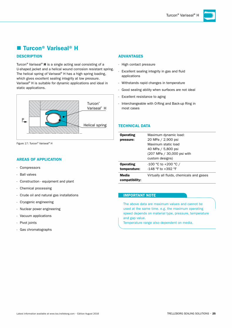
Turcon® Variseal® H
� Turcon® Variseal® HADVAnTAGeS
- High contact pressure
- Excellent sealing integrity in gas and fluid applications
- Withstands rapid changes in temperature
- Good sealing ability when surfaces are not ideal
- Excellent resistance to aging
- Interchangeable with O-Ring and Back-up Ring in most cases
TeCHnICAL DATA
Operating pressure:
Maximum dynamic load: 20 MPa / 2,900 psi Maximum static load 40 MPa / 5,800 psi (207 MPa / 30,000 psi with custom designs)
Operating temperature:
-100 °C to +200 °C /-148 °F to +392 °F
Media compatibility:
Virtually all fluids, chemicals and gases
IMPORTAnT nOTe
The above data are maximum values and cannot be used at the same time. e.g. the maximum operating speed depends on material type, pressure, temperature and gap value. Temperature range also dependent on media.
DeSCRIPTIOn
Turcon® Variseal® H is a single acting seal consisting of a U-shaped jacket and a helical wound corrosion resistant spring.The helical spring of Variseal® H has a high spring loading, which gives excellent sealing integrity at low pressure. Variseal® H is suitable for dynamic applications and ideal in static applications.
Turcon® Variseal® H
Helical springP
Figure 17: Turcon® Variseal® H
AReAS OF APPLICATIOn
- Compressors
- Ball valves
- Construction - equipment and plant
- Chemical processing
- Crude oil and natural gas installations
- Cryogenic engineering
- Nuclear power engineering
- Vacuum applications
- Pivot joints
- Gas chromatographs

26 • TRELLEBORG SEALING SOLUTIONS Latest information available at www.tss.trelleborg.com • Edition August 2016
TURCON® VARISEAL® · Rod Seals – Types M2, M2S, W2 and H
� Installation Recommendations for Rod Seals – Types M2, M2S, W2 and H – Metric
Variseal® M2
RVA RVJ RVC RVE
Variseal® W2 Variseal® M2S Variseal® H
r1
L1
h
Sm
ax.
d N h
9
D1 H
9
Figure 18: Installation Drawing
Table 12: Installation Dimensions – Metric
Series number for Types Rod Diameter dn h9 h D1 L1 r1 Radial Clearance Smax
M2 M2S W2 HStandard Range
extended Range
Groove Depth
Groove Diameter
Groove Width
Radius 2 MPa
10 MPa
20 MPa
40 MPa
H9 +0.2 Max
RVA0 RVC0 RVJ0 RVE0 3.0 - 9.9 3.0 - 40.0 1.45 dN + 2.9 2.4 0.25 0.20 0.10 0.08 0.05
RVA1 RVC1 RVJ1 RVE1 10.0 - 19.9 6.0 - 200.0 2.25 dN + 4.5 3.6 0.38 0.25 0.15 0.10 0.07
RVA2 RVC2 RVJ2 RVE2 20.0 - 39.9 10.0 - 400.0 3.10 dN + 6.2 4.8 0.38 0.35 0.20 0.15 0.08
RVA3 RVC3 RVJ3 RVE3 40.0 - 119.9 20.0 - 700.0 4.70 dN + 9.4 7.1 0.38 0.50 0.25 0.20 0.10
RVA4 RVC4 RVJ4 RVE4 120.0 - 999.9 35.0 - 1600.0 6.10 dN + 12.2 9.5 0.51 0.60 0.30 0.25 0.12
RVA5 RVC5 RVJ5 RVE5 1000.0 - 2500.0 80.0 -2500.0 9.50 dN + 19.0 15.0 0.51 0.90 0.50 0.40 0.20
Table 13: Size Series – Metric
dn D1 TSS Part no.
3.0 5.9 RV_0_0030
4.0 6.9 RV_0_0040
5.0 7.9 RV_0_0050
6.0 8.9 RV_0_0060
8.0 10.9 RV_0_0080
10.0 14.5 RV_1_0100
12.0 16.5 RV_1_0120
14.0 18.5 RV_1_0140
15.0 19.5 RV_1_0150
16.0 20.5 RV_1_0160
18.0 22.5 RV_1_0180
20.0 26.2 RV_2_0200
22.0 28.2 RV_2_0220
25.0 31.2 RV_2_0250
28.0 34.2 RV_2_0280
30.0 36.2 RV_2_0300
dn D1 TSS Part no.
32.0 38.2 RV_2_0320
35.0 41.2 RV_2_0350
36.0 42.2 RV_2_0360
40.0 49.4 RV_3_0400
42.0 51.4 RV_3_0420
45.0 54.4 RV_3_0450
48.0 57.4 RV_3_0480
50.0 59.4 RV_3_0500
52.0 61.4 RV_3_0520
55.0 64.4 RV_3_0550
56.0 65.4 RV_3_0560
60.0 69.4 RV_3_0600
63.0 72.4 RV_3_0630
65.0 74.4 RV_3_0650
70.0 79.4 RV_3_0700
75.0 84.4 RV_3_0750
dn D1 TSS Part no.
80.0 89.4 RV_3_0800
85.0 94.4 RV_3_0850
90.0 99.4 RV_3_0900
95.0 104.4 RV_3_0950
100.0 109.4 RV_3_1000
105.0 114.4 RV_3_1050
110.0 119.4 RV_3_1100
115.0 124.4 RV_3_1150
120.0 132.2 RV_4_1200
125.0 137.2 RV_4_1250
130.0 142.2 RV_4_1300
135.0 147.2 RV_4_1350
140.0 152.2 RV_4_1400Rod diameters in bold type correspond to the recommendations of ISO 3320. For additional size and part number details please contact your local Trelleborg Sealing Solutions Marketing company.

TRELLEBORG SEALING SOLUTIONS • 27Latest information available at www.tss.trelleborg.com • Edition August 2016
Rod Seals – Types M2, M2S, W2 and H
Table 14: Part number System for Rod Variseal® – Metric
Article CodeCross-
SectionSize Class Seal Material Spring Material Spring Load
RVA Variseal M2 RVC Variseal M2S RVe Variseal H RVJ Variseal W2
0 1.451 2.252 3.10 3 4.70 4 6.105 9.50
With notches0xxxx Rod dia <1000 (dia x 10.0)Xxxxx Rod dia. >= 1000 (dia x 1.0)
no notchesnxxxx Rod dia <1000 (dia x 10.0)Vxxxx Rod dia. >= 1000 (dia x 1.0)
- IndustrialA Aerospace
T01MF1MF4MF6T05T07 See page 7T12 for material T24 descriptionT40M79Z48Z80
S Stainless Steel H Hastelloy e Elgiloy
Standard load for each
design
RVA & RVCM MediumR High Clean
RVeH Heavy
RVJM Medium
ORDeRInG eXAMPLe 1
R V A 3 0 0 8 0 0 - T 4 0 S M
DesignRod Seal
Variseal M2
Cross-Section4.70 mm
SizeNotched seal designLeading indicator is 0 therefore 0800 size number represents a
80.0 mm rod diameter
ClassIndustrial
Jacket MaterialT40
Spring MaterialStainless steel
Medium spring load
ORDeRInG eXAMPLe 2
R V e 5 V 1 2 0 0 - T 4 0 S H
DesignRod SealVariseal H
Cross-Section9.50 mm
SizeNot Notched seal
designLeading indicator is V therefore 1200 size number represents a
1200.0 mm rod diameter
ClassIndustrial
Jacket MaterialT40
Spring MaterialStainless steel
Heavy spring load

28 • TRELLEBORG SEALING SOLUTIONS Latest information available at www.tss.trelleborg.com • Edition August 2016
� Installation Recommendations for Rod Seals – Types M2, M2S, W2 and H – Inch
Variseal® M2
RVA RVJ RVC RVE
Variseal® W2 Variseal® M2S Variseal® H
r1
L1
h
Sm
ax.
d N h
9
D1 H
9
Figure 19: Installation Drawing
Table 15: Installation Dimensions – Inch
Series number for Types h L1 r1 Radial Clearance Smax
M2 M2S W2 HGroove Depth
Groove Width
Radius290 psi 1,450 psi 2,900 psi 5,800 psi
+0.010 Max
RVAA RVCA RVJA RVEA 0.062 0.094 0.010 0.008 0.004 0.003 0.002
RVAB RVCB RVJB RVEB 0.093 0.141 0.015 0.010 0.006 0.004 0.003
RVAC RVCC RVJC RVEC 0.125 0.188 0.015 0.014 0.008 0.006 0.003
RVAD RVCD RVJD RVED 0.187 0.281 0.015 0.020 0.010 0.008 0.004
RVAE RVCE RVJE RVEE 0.250 0.375 0.020 0.024 0.012 0.010 0.005
RVAG RVCG RVJG RVEG 0.375 0.591 0.020 0.030 0.015 0.012 0.006
Table 16: Size Series – Inch
TURCON® VARISEAL® · Rod Seals – Types M2, M2S, W2 and H
dn D1 TSS Part no.
0.125 0.250 RV_A_B006
0.156 0.281 RV_A_B007
0.187 0.312 RV_A_B008
0.187 0.375 RV_B_B106
0.219 0.343 RV_A_B009
0.219 0.406 RV_B_B107
0.250 0.375 RV_A_B010
0.250 0.437 RV_B_B108
0.250 0.500 RV_C_B202
0.312 0.437 RV_A_B011
0.312 0.500 RV_B_B109
0.312 0.562 RV_C_B203
0.375 0.500 RV_A_B012
0.375 0.562 RV_B_B110
0.375 0.625 RV_C_B204
0.437 0.562 RV_A_B013
dn D1 TSS Part no.
0.437 0.625 RV_B_B111
0.437 0.687 RV_C_B205
0.500 0.625 RV_A_B014
0.500 0.687 RV_B_B112
0.500 0.750 RV_C_B206
0.562 0.687 RV_A_B015
0.562 0.750 RV_B_B113
0.562 0.812 RV_C_B207
0.625 0.750 RV_A_B016
0.625 0.812 RV_B_B114
0.625 0.875 RV_C_B208
0.687 0.812 RV_A_B017
0.687 0.875 RV_B_B115
0.687 0.937 RV_C_B209
0.750 0.875 RV_A_B018
0.750 0.937 RV_B_B116
dn D1 TSS Part no.
0.750 1.000 RV_C_B210
0.812 0.937 RV_A_B019
0.812 1.000 RV_B_B117
0.812 1.062 RV_C_B211
0.875 1.000 RV_A_B020
0.875 1.062 RV_B_B118
0.875 1.125 RV_C_B212
0.875 1.250 RV_D_B316
0.937 1.062 RV_A_B021
0.937 1.125 RV_B_B119
0.937 1.187 RV_C_B213
0.937 1.312 RV_D_B317
1.000 1.125 RV_A_B022
1.000 1.187 RV_B_B120
1.000 1.250 RV_C_B214
1.000 1.375 RV_D_B318

TRELLEBORG SEALING SOLUTIONS • 29Latest information available at www.tss.trelleborg.com • Edition August 2016
dn D1 TSS Part no.
1.062 1.187 RV_A_B023
1.062 1.250 RV_B_B121
1.062 1.312 RV_C_B215
1.062 1.437 RV_D_B319
1.125 1.250 RV_A_B024
1.125 1.312 RV_B_B122
1.125 1.375 RV_C_B216
1.125 1.500 RV_D_B320
1.187 1.312 RV_A_B025
1.187 1.375 RV_B_B123
1.187 1.437 RV_C_B217
1.187 1.562 RV_D_B321
1.250 1.375 RV_A_B026
1.250 1.437 RV_B_B124
1.250 1.500 RV_C_B218
1.250 1.625 RV_D_B322
1.312 1.437 RV_A_B027
1.312 1.500 RV_B_B125
1.312 1.562 RV_C_B219
1.312 1.687 RV_D_B323
1.375 1.500 RV_A_B028
1.375 1.562 RV_B_B126
1.375 1.625 RV_C_B220
1.375 1.750 RV_D_B324
1.437 1.625 RV_B_B127
1.437 1.687 RV_C_B221
1.500 1.625 RV_A_B029
1.500 1.687 RV_B_B128
1.500 1.750 RV_C_B222
1.500 1.875 RV_D_B325
1.500 2.000 RV_E_B401
1.562 1.750 RV_B_B129
1.625 1.750 RV_A_B030
1.625 1.812 RV_B_B130
1.625 1.875 RV_C_B223
1.625 2.000 RV_D_B326
1.625 2.125 RV_E_B402
1.687 1.875 RV_B_B131
1.750 1.875 RV_A_B031
1.750 1.937 RV_B_B132
1.750 2.000 RV_C_B224
1.750 2.125 RV_D_B327
1.750 2.250 RV_E_B403
1.812 2.000 RV_B_B133
1.875 2.000 RV_A_B032
dn D1 TSS Part no.
1.875 2.062 RV_B_B134
1.875 2.125 RV_C_B225
1.875 2.250 RV_D_B328
1.875 2.375 RV_E_B404
1.937 2.125 RV_B_B135
2.000 2.125 RV_A_B033
2.000 2.187 RV_B_B136
2.000 2.250 RV_C_B226
2.000 2.375 RV_D_B329
2.000 2.500 RV_E_B405
2.062 2.250 RV_B_B137
2.125 2.250 RV_A_B034
2.125 2.312 RV_B_B138
2.125 2.375 RV_C_B227
2.125 2.500 RV_D_B330
2.125 2.625 RV_E_B406
2.187 2.375 RV_B_B139
2.250 2.375 RV_A_B035
2.250 2.437 RV_B_B140
2.250 2.500 RV_C_B228
2.250 2.625 RV_D_B331
2.250 2.750 RV_E_B407
2.312 2.500 RV_B_B141
2.375 2.500 RV_A_B036
2.375 2.562 RV_B_B142
2.375 2.625 RV_C_B229
2.375 2.750 RV_D_B332
2.375 2.875 RV_E_B408
2.437 2.625 RV_B_B143
2.500 2.625 RV_A_B037
2.500 2.687 RV_B_B144
2.500 2.750 RV_C_B230
2.500 2.875 RV_D_B333
2.500 3.000 RV_E_B409
2.562 2.750 RV_B_B145
2.625 2.750 RV_A_B038
2.625 2.812 RV_B_B146
2.625 2.875 RV_C_B231
2.625 3.000 RV_D_B334
2.625 3.125 RV_E_B410
2.687 2.875 RV_B_B147
2.750 2.875 RV_A_B039
2.750 2.937 RV_B_B148
2.750 3.000 RV_C_B232
2.750 3.125 RV_D_B335
dn D1 TSS Part no.
2.750 3.250 RV_E_B411
2.812 3.000 RV_B_B149
2.875 3.000 RV_A_B040
2.875 3.062 RV_B_B150
2.875 3.125 RV_C_B233
2.875 3.250 RV_D_B336
2.875 3.375 RV_E_B412
3.000 3.125 RV_A_B041
3.000 3.188 RV_B_B151
3.000 3.250 RV_C_B234
3.000 3.375 RV_D_B337
3.000 3.500 RV_E_B413
3.125 3.375 RV_C_B235
3.125 3.500 RV_D_B338
3.125 3.625 RV_E_B414
3.250 3.375 RV_A_B042
3.250 3.437 RV_B_B152
3.250 3.500 RV_C_B236
3.250 3.625 RV_D_B339
3.250 3.750 RV_E_B415
3.375 3.625 RV_C_B237
3.375 3.750 RV_D_B340
3.375 3.875 RV_E_B416
3.500 3.625 RV_A_B043
3.500 3.688 RV_B_B153
3.500 3.750 RV_C_B238
3.500 3.875 RV_D_B341
3.500 4.000 RV_E_B417
3.625 3.875 RV_C_B239
3.625 4.000 RV_D_B342
3.625 4.125 RV_E_B418
3.750 3.875 RV_A_B044
3.750 3.937 RV_B_B154
3.750 4.000 RV_C_B240
3.750 4.125 RV_D_B343
3.750 4.250 RV_E_B419
3.875 4.125 RV_C_B241
3.875 4.250 RV_D_B344
3.875 4.375 RV_E_B420
4.000 4.125 RV_A_B045
4.000 4.187 RV_B_B155
4.000 4.250 RV_C_B242
4.000 4.375 RV_D_B345
4.000 4.500 RV_E_B421
4.125 4.375 RV_C_B243
Rod Seals – Types M2, M2S, W2 and H

30 • TRELLEBORG SEALING SOLUTIONS Latest information available at www.tss.trelleborg.com • Edition August 2016
dn D1 TSS Part no.
4.125 4.500 RV_D_B346
4.125 4.625 RV_E_B422
4.250 4.437 RV_B_B156
4.250 4.500 RV_C_B244
4.250 4.625 RV_D_B347
4.250 4.750 RV_E_B423
4.375 4.625 RV_C_B245
4.375 4.750 RV_D_B348
4.375 4.875 RV_E_B424
4.500 4.687 RV_B_B157
4.500 4.750 RV_C_B246
4.500 4.875 RV_D_B349
4.500 5.000 RV_E_B425
4.625 4.875 RV_C_B247
4.625 5.000 RV_D_B350
4.625 5.125 RV_E_B426
4.750 4.937 RV_B_B158
4.750 5.000 RV_C_B248
4.750 5.125 RV_D_B351
4.750 5.250 RV_E_B427
4.875 5.125 RV_C_B249
4.875 5.250 RV_D_B352
4.875 5.375 RV_E_B428
5.000 5.187 RV_B_B159
5.000 5.250 RV_C_B250
5.000 5.375 RV_D_B353
5.000 5.500 RV_E_B429
5.125 5.375 RV_C_B251
5.125 5.500 RV_D_B354
5.125 5.625 RV_e_B430
5.250 5.437 RV_B_B160
5.250 5.500 RV_C_B252
5.250 5.625 RV_D_B355
5.250 5.750 RV_e_B431
5.375 5.625 RV_C_B253
5.375 5.750 RV_D_B356
dn D1 TSS Part no.
5.375 5.875 RV_e_B432
5.500 5.687 RV_B_B161
5.500 5.750 RV_C_B254
5.500 5.875 RV_D_B357
5.500 6.000 RV_e_B433
5.625 5.875 RV_C_B255
5.625 6.000 RV_D_B358
5.625 6.125 RV_e_B434
5.750 6.000 RV_C_B256
5.750 6.125 RV_D_B359
5.750 6.250 RV_e_B435
5.875 6.125 RV_C_B257
5.875 6.250 RV_D_B360
5.875 6.375 RV_e_B436
6.000 6.250 RV_C_B258
6.000 6.375 RV_D_B361
6.000 6.500 RV_e_B437
6.250 6.500 RV_C_B259
6.250 6.625 RV_D_B362
6.250 6.750 RV_e_B438
6.500 6.750 RV_C_B260
6.500 6.875 RV_D_B363
6.500 7.000 RV_e_B439
6.750 7.000 RV_C_B261
6.750 7.125 RV_D_B364
6.750 7.250 RV_e_B440
7.000 7.250 RV_C_B262
7.000 7.375 RV_D_B365
7.000 7.500 RV_e_B441
7.250 7.500 RV_C_B263
7.250 7.625 RV_D_B366
7.250 7.750 RV_e_B442
7.500 7.750 RV_C_B264
7.500 7.875 RV_D_B367
7.500 8.000 RV_e_B443
7.750 8.000 RV_C_B265
dn D1 TSS Part no.
7.750 8.125 RV_D_B368
7.750 8.250 RV_e_B444
8.000 8.250 RV_C_B266
8.000 8.375 RV_D_B369
8.000 8.500 RV_e_B445
8.250 8.500 RV_C_B267
8.250 8.625 RV_D_B370
8.500 8.750 RV_C_B268
8.500 8.875 RV_D_B371
8.500 9.000 RV_e_B446
8.750 9.000 RV_C_B269
8.750 9.125 RV_D_B372
9.000 9.250 RV_C_B270
9.000 9.375 RV_D_B373
9.000 9.500 RV_e_B447
9.250 9.625 RV_D_B374
9.500 9.875 RV_D_B375
9.500 10.000 RV_e_B448
9.750 10.125 RV_D_B376
10.000 10.375 RV_D_B377
10.000 10.500 RV_e_B449
10.500 10.875 RV_D_B378
10.500 11.000 RV_e_B450
11.000 11.500 RV_e_B451
11.500 12.000 RV_e_B452
12.000 12.500 RV_e_B453
12.500 13.000 RV_e_B454
13.000 13.500 RV_e_B455
13.500 14.000 RV_e_B456
14.000 14.500 RV_e_B457
14.500 15.000 RV_e_B458
15.000 15.500 RV_e_B459
15.500 16.000 RV_e_B460
Figures in bold are preferred sizes. For additional size and part number details please contact your local Trelleborg Sealing Solutions Marketing company.
TURCON® VARISEAL® · Rod Seals – Types M2, M2S, W2 and H

TRELLEBORG SEALING SOLUTIONS • 31Latest information available at www.tss.trelleborg.com • Edition August 2016
Table 17: Part number System for Rod Variseal® – Inch
Article CodeCross-
SectionSize Class Seal Material Spring Material Spring Load
RVA Variseal M2 RVC Variseal M2S RVe Variseal H RVJ Variseal W2
InchA 0.062B 0.093C 0.125D 0.187e 0.250G 0.375
With notches0Bxxx Inch Dash #Sxxxx Rod dia <10.0 Inch (dia x 1000.0)Lxxxx Rod dia. >= 10.0 (dia x 100.0)
no notchesnBxxx Inch Dash #Rxxxx Rod dia <10.0 Inch (dia x 1000.0)Kxxxx Rod dia. >= 10.0 (dia x 100.0)
- IndustrialA Aerospace
T01MF1MF4MF6T05T07 See page 7T12 for materialT24 descriptionT40M79Z48Z80
S Stainless SteelH Hastelloye Elgiloy
Standard load for each
design
RVA & RVCM MediumR High Clean
RVeH Heavy
RVJM Medium
ORDeRInG eXAMPLe 1
R V A C n B 2 3 0 - T 4 0 S M
DesignRod Seal
Variseal M2
Cross-Section200 series
(0.125 inch)
SizeNot Notched seal
designLeading indicator is
NB therefore 230 is an inch dash number
ClassIndustrial
Jacket MaterialT40
Spring MaterialStainless steel
Medium spring load
ORDeRInG eXAMPLe 2
R V J D R 3 4 0 0 - T 4 0 S M
DesignRod Seal
Variseal W2
Cross-Section300 series
(0.187 Inch)
SizeNot Notched seal
designLeading indicator is R therefore 3400 size number represents a 3.400 inch rod
diameter
ClassIndustrial
Jacket MaterialT40
Spring MaterialStainless steel
Medium spring load
Rod Seals – Types M2, M2S, W2 and H

32 • TRELLEBORG SEALING SOLUTIONS Latest information available at www.tss.trelleborg.com • Edition August 2016
TURCON® VARISEAL® · AS4716 Rod Seals – Types M2, M2S, W2 and H
� Installation Recommendations for AS4716 Rod Seals – Types M2, M2S, W2 and H – Inch
Variseal® M2
RVA RVJ RVC RVE
Variseal® W2 Variseal® M2S Variseal® H
r1
L1
h
Sm
ax.
d N h
9
D1 H
9
Figure 20: Installation Drawing
Table 18: Installation Dimensions AS4716 – Inch
Series number for Types h L1 r1 Radial Clearance Smax
M2 M2S W2 HGroove Depth
Groove Width
Radius290 psi 1,450 psi 2,900 psi 5,800 psi
+0.010 Max
RVA0 RVC0 RVJ0 RVE0 0.056 0.094 0.010 0.008 0.004 0.003 0.002
RVA1 RVC1 RVJ1 RVE1 0.087 0.141 0.015 0.010 0.006 0.004 0.003
RVA2 RVC2 RVJ2 RVE2 0.122 0.188 0.015 0.014 0.008 0.006 0.003
RVA3 RVC3 RVJ3 RVE3 0.185 0.281 0.015 0.020 0.010 0.008 0.004
RVA4 RVC4 RVJ4 RVE4 0.239 0.375 0.020 0.024 0.012 0.010 0.005
AS4716 states hardware tolerances to h8/H8. However Variseals are suitable with h9/H9 tolerances. h9/H9 tolerance dimensions can be found using the ISO Fits & Tolerances App, see page 84.
Table 19: Standard Dash Sizes AS4716 – Inch
dn D1 TSS Part no.
0.123 0.232 RV_0_M006
0.154 0.264 RV_0_M007
0.185 0.294 RV_0_M008
0.185 0.359 RV_1_M106
0.217 0.327 RV_0_M009
0.217 0.392 RV_1_M107
0.248 0.359 RV_0_M010
0.248 0.423 RV_1_M108
0.310 0.421 RV_0_M011
0.310 0.486 RV_1_M109
0.373 0.484 RV_0_M012
0.373 0.546 RV_1_M110
0.435 0.545 RV_0_M013
0.435 0.609 RV_1_M111
dn D1 TSS Part no.
0.498 0.608 RV_0_M014
0.498 0.672 RV_1_M112
0.560 0.670 RV_0_M015
0.560 0.734 RV_1_M113
0.623 0.733 RV_0_M016
0.623 0.797 RV_1_M114
0.685 0.795 RV_0_M017
0.685 0.859 RV_1_M115
0.748 0.858 RV_0_M018
0.748 0.923 RV_1_M116
0.748 0.989 RV_2_M210
0.810 0.920 RV_0_M019
0.810 0.985 RV_1_M117
0.810 1.051 RV_2_M211
dn D1 TSS Part no.
0.873 0.983 RV_0_M020
0.873 1.048 RV_1_M118
0.873 1.115 RV_2_M212
0.935 1.045 RV_0_M021
0.935 1.110 RV_1_M119
0.935 1.177 RV_2_M213
0.998 1.108 RV_0_M022
0.998 1.173 RV_1_M120
0.998 1.240 RV_2_M214
1.060 1.170 RV_0_M023
1.060 1.235 RV_1_M121
1.060 1.302 RV_2_M215
1.123 1.233 RV_0_M024
1.123 1.298 RV_1_M122

TRELLEBORG SEALING SOLUTIONS • 33Latest information available at www.tss.trelleborg.com • Edition August 2016
dn D1 TSS Part no.
1.123 1.365 RV_2_M216
1.185 1.295 RV_0_M025
1.185 1.360 RV_1_M123
1.185 1.427 RV_2_M217
1.248 1.358 RV_0_M026
1.248 1.423 RV_1_M124
1.248 1.490 RV_2_M218
1.310 1.420 RV_0_M027
1.310 1.485 RV_1_M125
1.310 1.552 RV_2_M219
1.373 1.483 RV_0_M028
1.373 1.548 RV_1_M126
1.373 1.615 RV_2_M220
1.435 1.610 RV_1_M127
1.435 1.677 RV_2_M221
1.498 1.673 RV_1_M128
1.498 1.740 RV_2_M222
1.498 1.870 RV_3_M325
1.560 1.735 RV_1_M129
1.623 1.798 RV_1_M130
1.623 1.865 RV_2_M223
1.623 1.995 RV_3_M326
1.685 1.860 RV_1_M131
1.748 1.923 RV_1_M132
1.748 1.990 RV_2_M224
1.748 2.120 RV_3_M327
1.810 1.984 RV_1_M133
1.873 2.047 RV_1_M134
1.873 2.115 RV_2_M225
1.873 2.245 RV_3_M328
1.936 2.110 RV_1_M135
1.998 2.172 RV_1_M136
1.998 2.240 RV_2_M226
1.998 2.370 RV_3_M329
2.061 2.235 RV_1_M137
2.123 2.297 RV_1_M138
2.123 2.365 RV_2_M227
2.123 2.495 RV_3_M330
2.186 2.360 RV_1_M139
2.248 2.422 RV_1_M140
2.248 2.490 RV_2_M228
2.248 2.620 RV_3_M331
2.311 2.485 RV_1_M141
2.373 2.547 RV_1_M142
dn D1 TSS Part no.
2.373 2.615 RV_2_M229
2.373 2.745 RV_3_M332
2.436 2.610 RV_1_M143
2.498 2.672 RV_1_M144
2.498 2.740 RV_2_M230
2.498 2.870 RV_3_M333
2.561 2.735 RV_1_M145
2.623 2.797 RV_1_M146
2.623 2.865 RV_2_M231
2.623 2.995 RV_3_M334
2.685 2.860 RV_1_M147
2.748 2.922 RV_1_M148
2.748 2.990 RV_2_M232
2.748 3.120 RV_3_M335
2.811 2.985 RV_1_M149
2.873 3.115 RV_2_M233
2.873 3.245 RV_3_M336
2.997 3.239 RV_2_M234
2.997 3.369 RV_3_M337
3.122 3.364 RV_2_M235
3.122 3.494 RV_3_M338
3.247 3.489 RV_2_M236
3.247 3.619 RV_3_M339
3.372 3.614 RV_2_M237
3.372 3.744 RV_3_M340
3.497 3.739 RV_2_M238
3.497 3.869 RV_3_M341
3.622 3.864 RV_2_M239
3.622 3.994 RV_3_M342
3.747 3.989 RV_2_M240
3.747 4.119 RV_3_M343
3.872 4.114 RV_2_M241
3.872 4.244 RV_3_M344
3.997 4.239 RV_2_M242
3.997 4.369 RV_3_M345
4.122 4.364 RV_2_M243
4.122 4.494 RV_3_M346
4.247 4.489 RV_2_M244
4.247 4.619 RV_3_M347
4.372 4.614 RV_2_M245
4.372 4.744 RV_3_M348
4.497 4.739 RV_2_M246
4.497 4.869 RV_3_M349
4.497 4.974 RV_4_M425
dn D1 TSS Part no.
4.622 5.099 RV_4_M426
4.747 5.224 RV_4_M427
4.872 5.349 RV_4_M428
4.997 5.474 RV_4_M429
5.122 5.599 RV_4_M430
5.247 5.724 RV_4_M431
5.372 5.849 RV_4_M432
5.497 5.974 RV_4_M433
5.622 6.099 RV_4_M434
5.747 6.224 RV_4_M435
5.872 6.349 RV_4_M436
5.997 6.474 RV_4_M437
6.247 6.724 RV_4_M438
6.497 6.974 RV_4_M439
6.747 7.224 RV_4_M440
6.997 7.474 RV_4_M441
7.247 7.724 RV_4_M442
7.497 7.974 RV_4_M443
7.747 8.224 RV_4_M444
7.997 8.474 RV_4_M445
8.497 8.974 RV_4_M446
8.997 9.474 RV_4_M447
9.497 9.974 RV_4_M448
9.997 10.474 RV_4_M449
10.497 10.974 RV_4_M450
10.997 11.474 RV_4_M451
11.497 11.974 RV_4_M452
11.997 12.474 RV_4_M453
12.497 12.974 RV_4_M454
12.997 13.474 RV_4_M455
13.497 13.974 RV_4_M456
13.997 14.474 RV_4_M457
14.497 14.974 RV_4_M458
14.997 15.474 RV_4_M459
15.497 15.974 RV_4_M460
Figures in bold are preferred sizes. For additional size and part number details please contact your local Trelleborg Sealing Solutions Marketing company.
AS4716 Rod Seals – Types M2, M2S, W2 and H

34 • TRELLEBORG SEALING SOLUTIONS Latest information available at www.tss.trelleborg.com • Edition August 2016
Table 20: Part number System for AS4716 Rod Variseal® – Inch
Article CodeCross-
SectionSize Class Seal Material Spring Material Spring Load
RVA Variseal M2 RVC Variseal M2S RVe Variseal H RVJ Variseal W2
AS47160 0.0561 0.0872 0.1223 0.1854 0.239
With notches0Mxxx AS4716 Dash #Sxxxx Rod dia <10.0 Inch (dia x 1000.0)Lxxxx Rod dia. >= 10.0 (dia x 100.0)
no notchesnMxxx AS4716 Dash #Rxxxx Rod dia <10.0 Inch (dia x 1000.0)Kxxxx Rod dia. >= 10.0 (dia x 100.0)
- IndustrialA Aerospace
T01MF1MF4MF6T05T07 See page 7T12 for materialT24 descriptionT40M79Z48Z80
S Stainless SteelH Hastelloye Elgiloy
Standard load for each
design
RVA & RVCM MediumR High Clean
RVeH Heavy
RVJM Medium
ORDeRInG eXAMPLe 1
R V A 2 n M 2 3 0 A T 4 0 S M
DesignRod Seal
Variseal M2
Cross-Section200 series
(0.122 inch)
SizeNot Notched seal
designLeading indicator is
NM therefore 230 is an inch dash number
ClassAerospace
Jacket MaterialT40
Spring MaterialStainless steel
Medium spring load
ORDeRInG eXAMPLe 2
R V J 3 R 3 4 0 0 A T 4 0 S M
DesignRod Seal
Variseal W2
Cross-Section300 series
(0.185 Inch)
SizeNot Notched seal
designLeading indicator is R therefore 3400 size number represents a
3.400 inch rod diameter
ClassAerospace
Jacket MaterialT40
Spring MaterialStainless steel
Medium spring load
TURCON® VARISEAL® · AS4716 Rod Seals – Types M2, M2S, W2 and H
TRELLEBORG SEALING SOLUTIONS • 35Latest information available at www.tss.trelleborg.com • Edition August 2016
AS4716 Rod Seals – Types M2, M2S, W2 and H

TURCON® VARISEAL® · Piston Seals – Types M2, M2S, W2 and H
36 • TRELLEBORG SEALING SOLUTIONS Latest information available at www.tss.trelleborg.com • Edition August 2016
� Installation Recommendations for Piston Seals – Types M2, M2S, W2 and H – Metric
Variseal® M2
PVA PVJ PVC PVE
Variseal® W2 Variseal® M2S Variseal® H
hd 1
h9
DN H
9
S
r1
L1
Figure 21: Installation Drawing
Table 21: Installation Dimensions – Metric
Series number for Types Bore Diameter Dn H9 h d1 L1 r1 Radial Clearance Smax
M2 M2S W2 H Standard Rangeextended
RangeGroove Depth
Groove Diameter
Groove Width
Radius 2
MPa
10
MPa
20
MPa
40
MPah9 +0.2 Max
PVA0 PVC0 PVJ0 PVE0 6.0 - 13.9 6.0 - 40.0 1.45 DN - 2.9 2.4 0.25 0.20 0.10 0.08 0.05
PVA1 PVC1 PVJ1 PVE1 14.0 - 24.9 10.0 - 200.0 2.25 DN - 4.5 3.6 0.38 0.25 0.15 0.10 0.07
PVA2 PVC2 PVJ2 PVE2 25.0 - 45.9 16.0 - 400.0 3.10 DN - 6.2 4.8 0.38 0.35 0.20 0.15 0.08
PVA3 PVC3 PVJ3 PVE3 46.0 - 124.9 28.0 - 700.0 4.70 DN - 9.4 7.1 0.38 0.50 0.25 0.20 0.10
PVA4 PVC4 PVJ4 PVE4 125.0 - 999.9 45.0 - 1600.0 6.10 DN - 12.2 9.5 0.51 0.60 0.30 0.25 0.12
PVA5 PVC5 PVJ5 PVE5 1000.0 - 2500.0 100.0 - 2500.0 9.50 DN - 19.0 15.0 0.51 0.90 0.50 0.40 0.20
h9/H9 tolerance dimensions can be found using the ISO Fits & Tolerances App, see page 84.
Table 22: Size Series – Metric
Dn d1 TSS Part no.
6.0 3.1 PV_0_0060
8.0 5.1 PV_0_0080
10.0 7.1 PV_0_0100
12.0 9.1 PV_0_0120
14.0 9.5 PV_1_0140
15.0 10.5 PV_1_0150
16.0 11.5 PV_1_0160
18.0 13.5 PV_1_0180
20.0 15.5 PV_1_0200
22.0 17.5 PV_1_0220
25.0 18.8 PV_2_0250
28.0 21.8 PV_2_0280
30.0 23.8 PV_2_0300
32.0 25.8 PV_2_0320
35.0 28.8 PV_2_0350
40.0 33.8 PV_2_0400
42.0 35.8 PV_2_0420
45.0 38.8 PV_2_0450
Dn d1 TSS Part no.
48.0 38.6 PV_3_0480
50.0 40.6 PV_3_0500
52.0 42.6 PV_3_0520
55.0 45.6 PV_3_0550
60.0 50.6 PV_3_0600
63.0 53.6 PV_3_0630
65.0 55.6 PV_3_0650
70.0 60.6 PV_3_0700
75.0 65.6 PV_3_0750
80.0 70.6 PV_3_0800
85.0 75.6 PV_3_0850
90.0 80.6 PV_3_0900
95.0 85.6 PV_3_0950
100.0 90.6 PV_3_1000
105.0 95.6 PV_3_1050
110.0 100.6 PV_3_1100
115.0 105.6 PV_3_1150
120.0 110.6 PV_3_1200
Dn d1 TSS Part no.
125.0 112.8 PV_4_1250
130.0 117.8 PV_4_1300
135.0 122.8 PV_4_1350
140.0 127.8 PV_4_1400
150.0 137.8 PV_4_1500
160.0 147.8 PV_4_1600
170.0 157.8 PV_4_1700
180.0 167.8 PV_4_1800
190.0 177.8 PV_4_1900
200.0 187.8 PV_4_2000
210.0 97.8 PV_4_2100
220.0 207.8 PV_4_2200
230.0 217.8 PV_4_2300
240.0 227.8 PV_4_2400
250.0 237.8 PV_4_2500
Rod diameters in bold type correspond to the recommendations of ISO 3320. For additional size and part number details please contact your local Trelleborg Sealing Solutions Marketing company.
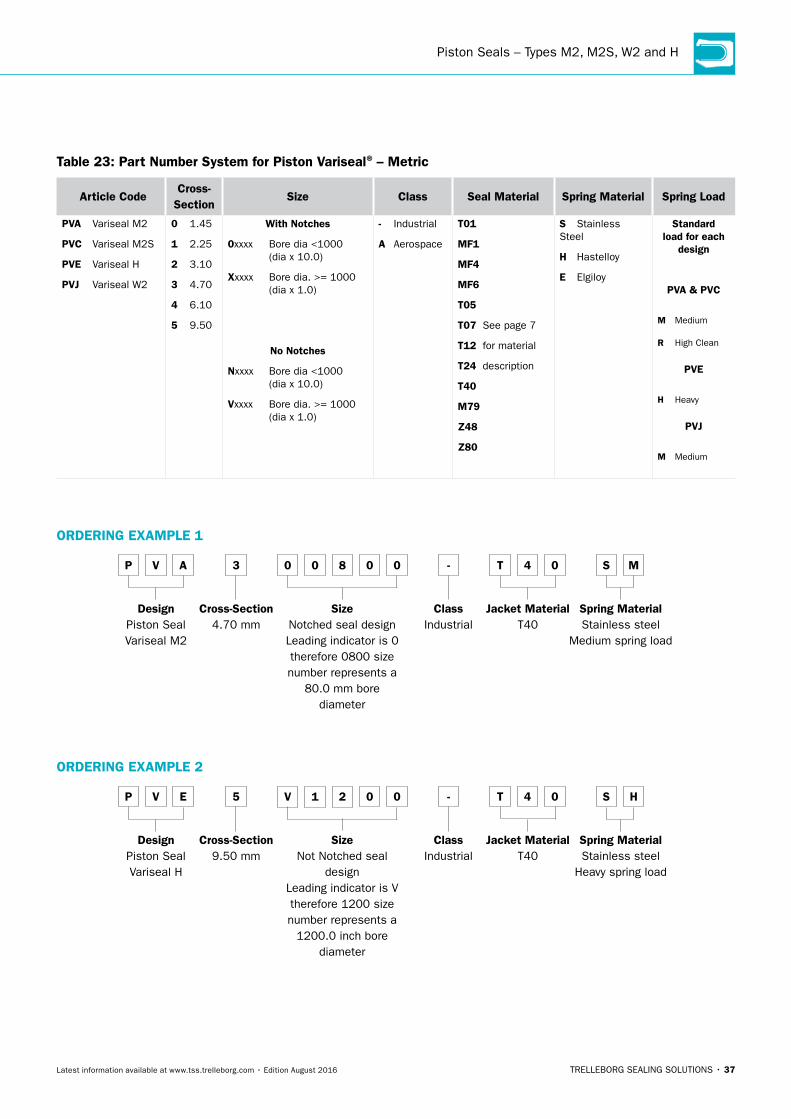
Piston Seals – Types M2, M2S, W2 and H
TRELLEBORG SEALING SOLUTIONS • 37Latest information available at www.tss.trelleborg.com • Edition August 2016
Table 23: Part number System for Piston Variseal® – Metric
Article CodeCross-
SectionSize Class Seal Material Spring Material Spring Load
PVA Variseal M2
PVC Variseal M2S
PVe Variseal H
PVJ Variseal W2
0 1.45
1 2.25
2 3.10
3 4.70
4 6.10
5 9.50
With notches
0xxxx Bore dia <1000 (dia x 10.0)
Xxxxx Bore dia. >= 1000 (dia x 1.0)
no notches
nxxxx Bore dia <1000 (dia x 10.0)
Vxxxx Bore dia. >= 1000 (dia x 1.0)
- Industrial
A Aerospace
T01
MF1
MF4
MF6
T05
T07 See page 7
T12 for material
T24 description
T40
M79
Z48
Z80
S Stainless Steel
H Hastelloy
e Elgiloy
Standard load for each
design
PVA & PVC
M Medium
R High Clean
PVe
H Heavy
PVJ
M Medium
ORDeRInG eXAMPLe 1
P V A 3 0 0 8 0 0 - T 4 0 S M
DesignPiston SealVariseal M2
Cross-Section4.70 mm
SizeNotched seal designLeading indicator is 0 therefore 0800 size number represents a
80.0 mm bore diameter
ClassIndustrial
Jacket MaterialT40
Spring MaterialStainless steel
Medium spring load
ORDeRInG eXAMPLe 2
P V e 5 V 1 2 0 0 - T 4 0 S H
DesignPiston SealVariseal H
Cross-Section9.50 mm
SizeNot Notched seal
designLeading indicator is V therefore 1200 size number represents a
1200.0 inch bore diameter
ClassIndustrial
Jacket MaterialT40
Spring MaterialStainless steel
Heavy spring load

TURCON® VARISEAL® · Piston Seals – Types M2, M2S, W2 and H
38 • TRELLEBORG SEALING SOLUTIONS Latest information available at www.tss.trelleborg.com • Edition August 2016
� Installation Recommendation for Piston Seals – Types M2, M2S, W2 and H – Inch
Variseal® M2
PVA PVJ PVC PVE
Variseal® W2 Variseal® M2S Variseal® H
hd 1
h9
DN H
9
S
r1
L1
Figure 22: Installation Drawing
Table 24: Installation Dimensions – Inch
Series number for Types h L1 r1 Radial Clearance Smax
M2 M2S W2 HGroove Depth
Groove Width
Radius290 psi 1,450 psi 2,900 psi 5,800 psi
+0.010 Max
PVAA PVCA PVJA PVEA 0.062 0.094 0.010 0.008 0.004 0.003 0.002
PVAB PVCB PVJB PVEB 0.093 0.141 0.015 0.010 0.006 0.004 0.003
PVAC PVCC PVJC PVEC 0.125 0.188 0.015 0.014 0.008 0.006 0.003
PVAD PVCD PVJD PVED 0.187 0.281 0.015 0.020 0.010 0.008 0.004
PVAE PVCE PVJE PVEE 0.250 0.375 0.020 0.024 0.012 0.010 0.005
PVAG PVAG PVJG PVEG 0.375 0.591 0.020 0.030 0.015 0.012 0.006
h9/H9 tolerance dimensions can be found using the ISO Fits & Tolerances App, see page 84.
Table 25: Standard Dash Sizes – Inch
Dn d1 TSS Part no.
0.250 0.125 PV_A_B006
0.281 0.156 PV_A_B007
0.312 0.187 PV_A_B008
0.343 0.218 PV_A_B009
0.375 0.250 PV_A_B010
0.375 0.187 PV_B_B106
0.406 0.219 PV_B_B107
0.437 0.312 PV_A_B011
0.437 0.250 PV_B_B108
0.500 0.375 PV_A_B012
0.500 0.312 PV_B_B109
0.500 0.250 PV_C_B202
0.562 0.437 PV_A_B013
0.562 0.375 PV_B_B110
0.562 0.312 PV_C_B203
0.625 0.500 PV_A_B014
Dn d1 TSS Part no.
0.625 0.437 PV_B_B111
0.625 0.375 PV_C_B204
0.687 0.562 PV_A_B015
0.687 0.500 PV_B_B112
0.687 0.437 PV_C_B205
0.750 0.625 PV_A_B016
0.750 0.562 PV_B_B113
0.750 0.500 PV_C_B206
0.812 0.687 PV_A_B017
0.812 0.625 PV_B_B114
0.812 0.562 PV_C_B207
0.875 0.750 PV_A_B018
0.875 0.687 PV_B_B115
0.875 0.625 PV_C_B208
0.937 0.812 PV_A_B019
0.937 0.750 PV_B_B116
Dn d1 TSS Part no.
0.937 0.687 PV_C_B209
1.000 0.875 PV_A_B020
1.000 0.812 PV_B_B117
1.000 0.750 PV_C_B210
1.062 0.937 PV_A_B021
1.062 0.875 PV_B_B118
1.062 0.812 PV_C_B211
1.125 1.000 PV_A_B022
1.125 0.937 PV_B_B119
1.125 0.875 PV_C_B212
1.187 1.062 PV_A_B023
1.187 1.000 PV_B_B120
1.187 0.937 PV_C_B213
1.250 1.125 PV_A_B024
1.250 1.062 PV_B_B121
1.250 1.000 PV_C_B214

Piston Seals – Types M2, M2S, W2 and H
TRELLEBORG SEALING SOLUTIONS • 39Latest information available at www.tss.trelleborg.com • Edition August 2016
Dn d1 TSS Part no.
1.250 0.875 PV_D_B316
1.312 1.187 PV_A_B025
1.312 1.125 PV_B_B122
1.312 1.062 PV_C_B215
1.312 0.937 PV_D_B317
1.375 1.250 PV_A_B026
1.375 1.187 PV_B_B123
1.375 1.125 PV_C_B216
1.375 1.000 PV_D_B318
1.437 1.312 PV_A_B027
1.437 1.250 PV_B_B124
1.437 1.187 PV_C_B217
1.437 1.062 PV_D_B319
1.500 1.375 PV_A_B028
1.500 1.312 PV_B_B125
1.500 1.250 PV_C_B218
1.500 1.125 PV_D_B320
1.562 1.375 PV_B_B126
1.562 1.312 PV_C_B219
1.562 1.187 PV_D_B321
1.625 1.500 PV_A_B029
1.625 1.437 PV_B_B127
1.625 1.375 PV_C_B220
1.625 1.250 PV_D_B322
1.687 1.500 PV_B_B128
1.687 1.437 PV_C_B221
1.687 1.312 PV_D_B323
1.750 1.625 PV_A_B030
1.750 1.562 PV_B_B129
1.750 1.500 PV_C_B222
1.750 1.375 PV_D_B324
1.812 1.625 PV_B_B130
1.875 1.750 PV_A_B031
1.875 1.687 PV_B_B131
1.875 1.625 PV_C_B223
1.875 1.500 PV_D_B325
1.937 1.750 PV_B_B132
2.000 1.875 PV_A_B032
2.000 1.812 PV_B_B133
2.000 1.750 PV_C_B224
2.000 1.625 PV_D_B326
2.000 1.500 PV_E_B401
2.062 1.875 PV_B_B134
2.125 2.000 PV_A_B033
2.125 1.937 PV_B_B135
Dn d1 TSS Part no.
2.125 1.875 PV_C_B225
2.125 1.750 PV_D_B327
2.125 1.625 PV_E_B402
2.187 2.000 PV_B_B136
2.250 2.125 PV_A_B034
2.250 2.062 PV_B_B137
2.250 2.000 PV_C_B226
2.250 1.875 PV_D_B328
2.250 1.750 PV_E_B403
2.312 2.125 PV_B_B138
2.375 2.250 PV_A_B035
2.375 2.187 PV_B_B139
2.375 2.125 PV_C_B227
2.375 2.000 PV_D_B329
2.375 1.875 PV_E_B404
2.437 2.250 PV_B_B140
2.500 2.375 PV_A_B036
2.500 2.312 PV_B_B141
2.500 2.250 PV_C_B228
2.500 2.125 PV_D_B330
2.500 2.000 PV_E_B405
2.562 2.375 PV_B_B142
2.625 2.500 PV_A_B037
2.625 2.437 PV_B_B143
2.625 2.375 PV_C_B229
2.625 2.250 PV_D_B331
2.625 2.125 PV_E_B406
2.687 2.500 PV_B_B144
2.750 2.625 PV_A_B038
2.750 2.562 PV_B_B145
2.750 2.500 PV_C_B230
2.750 2.375 PV_D_B332
2.750 2.250 PV_E_B407
2.812 2.625 PV_B_B146
2.875 2.750 PV_A_B039
2.875 2.687 PV_B_B147
2.875 2.625 PV_C_B231
2.875 2.500 PV_D_B333
2.875 2.375 PV_E_B408
2.937 2.750 PV_B_B148
3.000 2.875 PV_A_B040
3.000 2.812 PV_B_B149
3.000 2.750 PV_C_B232
3.000 2.625 PV_D_B334
3.000 2.500 PV_E_B409
Dn d1 TSS Part no.
3.062 2.875 PV_B_B150
3.125 3.000 PV_A_B041
3.125 2.875 PV_C_B233
3.125 2.750 PV_D_B335
3.125 2.625 PV_E_B410
3.188 3.000 PV_B_B151
3.250 3.000 PV_C_B234
3.250 2.875 PV_D_B336
3.250 2.750 PV_E_B411
3.375 3.250 PV_A_B042
3.375 3.125 PV_C_B235
3.375 3.000 PV_D_B337
3.375 2.875 PV_E_B412
3.437 3.250 PV_B_B152
3.500 3.250 PV_C_B236
3.500 3.125 PV_D_B338
3.500 3.000 PV_E_B413
3.625 3.500 PV_A_B043
3.625 3.375 PV_C_B237
3.625 3.250 PV_D_B339
3.625 3.125 PV_E_B414
3.688 3.500 PV_B_B153
3.750 3.500 PV_C_B238
3.750 3.375 PV_D_B340
3.750 3.250 PV_E_B415
3.875 3.750 PV_A_B044
3.875 3.625 PV_C_B239
3.875 3.500 PV_D_B341
3.875 3.375 PV_E_B416
3.937 3.750 PV_B_B154
4.000 3.750 PV_C_B240
4.000 3.625 PV_D_B342
4.000 3.500 PV_E_B417
4.125 4.000 PV_A_B045
4.125 3.875 PV_C_B241
4.125 3.750 PV_D_B343
4.125 3.625 PV_E_B418
4.187 4.000 PV_B_B155
4.250 4.000 PV_C_B242
4.250 3.875 PV_D_B344
4.250 3.750 PV_E_B419
4.375 4.125 PV_C_B243
4.375 4.000 PV_D_B345
4.375 3.875 PV_E_B420
4.437 4.250 PV_B_B156

TURCON® VARISEAL® · Piston Seals – Types M2, M2S, W2 and H
40 • TRELLEBORG SEALING SOLUTIONS Latest information available at www.tss.trelleborg.com • Edition August 2016
Dn d1 TSS Part no.
4.500 4.250 PV_C_B244
4.500 4.125 PV_D_B346
4.500 4.000 PV_E_B421
4.625 4.375 PV_C_B245
4.625 4.250 PV_D_B347
4.625 4.125 PV_E_B422
4.687 4.500 PV_B_B157
4.750 4.500 PV_C_B246
4.750 4.375 PV_D_B348
4.750 4.250 PV_E_B423
4.875 4.625 PV_C_B247
4.875 4.500 PV_D_B349
4.875 4.375 PV_E_B424
4.937 4.750 PV_B_B158
5.000 4.750 PV_C_B248
5.000 4.625 PV_D_B350
5.000 4.500 PV_E_B425
5.125 4.875 PV_C_B249
5.125 4.750 PV_D_B351
5.125 4.625 PV_E_B426
5.187 5.000 PV_B_B159
5.250 5.000 PV_C_B250
5.250 4.875 PV_D_B352
5.250 4.750 PV_E_B427
5.375 5.125 PV_C_B251
5.375 5.000 PV_D_B353
5.375 4.875 PV_E_B428
5.437 5.250 PV_B_B160
5.500 5.250 PV_C_B252
5.500 5.125 PV_D_B354
5.500 5.000 PV_e_B429
5.625 5.375 PV_C_B253
5.625 5.250 PV_D_B355
5.625 5.125 PV_e_B430
5.687 5.500 PV_B_B161
5.750 5.500 PV_C_B254
Dn d1 TSS Part no.
5.750 5.375 PV_D_B356
5.750 5.250 PV_e_B431
5.875 5.625 PV_C_B255
5.875 5.500 PV_D_B357
5.875 5.375 PV_e_B432
6.000 5.750 PV_C_B256
6.000 5.625 PV_D_B358
6.000 5.500 PV_e_B433
6.125 5.875 PV_C_B257
6.125 5.750 PV_D_B359
6.125 5.625 PV_e_B434
6.250 6.000 PV_C_B258
6.250 5.875 PV_D_B360
6.250 5.750 PV_e_B435
6.375 6.000 PV_D_B361
6.375 5.875 PV_e_B436
6.500 6.250 PV_C_B259
6.500 6.000 PV_e_B437
6.625 6.250 PV_D_B362
6.750 6.500 PV_C_B260
6.750 6.250 PV_e_B438
6.875 6.500 PV_D_B363
7.000 6.750 PV_C_B261
7.000 6.500 PV_e_B439
7.125 6.750 PV_D_B364
7.250 7.000 PV_C_B262
7.250 6.750 PV_e_B440
7.375 7.000 PV_D_B365
7.500 7.250 PV_C_B263
7.500 7.000 PV_e_B441
7.625 7.250 PV_D_B366
7.750 7.500 PV_C_B264
7.750 7.250 PV_e_B442
7.875 7.500 PV_D_B367
8.000 7.750 PV_C_B265
8.000 7.500 PV_e_B443
Dn d1 TSS Part no.
8.125 7.750 PV_D_B368
8.250 8.000 PV_C_B266
8.250 7.750 PV_e_B444
8.375 8.000 PV_D_B369
8.500 8.250 PV_C_B267
8.500 8.000 PV_e_B445
8.625 8.250 PV_D_B370
8.750 8.500 PV_C_B268
8.875 8.500 PV_D_B371
9.000 8.750 PV_C_B269
9.000 8.500 PV_e_B446
9.125 8.750 PV_D_B372
9.250 9.000 PV_C_B270
9.375 9.000 PV_D_B373
9.500 9.000 PV_e_B447
9.625 9.250 PV_D_B374
9.875 9.500 PV_D_B375
10.000 9.500 PV_e_B448
10.125 9.750 PV_D_B376
10.375 10.000 PV_D_B377
10.500 10.000 PV_e_B449
10.875 10.500 PV_D_B378
11.000 10.500 PV_e_B450
11.500 11.000 PV_e_B451
12.000 11.500 PV_e_B452
12.500 12.000 PV_e_B453
13.000 12.500 PV_e_B454
13.500 13.000 PV_e_B455
14.000 13.500 PV_e_B456
14.500 14.000 PV_e_B457
15.000 14.500 PV_e_B458
15.500 15.000 PV_e_B459
16.000 15.500 PV_e_B460
For additional size and part number details please contact your local Trelleborg Sealing Solutions Marketing company.

Piston Seals – Types M2, M2S, W2 and H
TRELLEBORG SEALING SOLUTIONS • 41Latest information available at www.tss.trelleborg.com • Edition August 2016
Table 26: Part number System for Piston Variseal® – Inch
Article CodeCross-
SectionSize Class Seal Material Spring Material Spring Load
PVA Variseal M2
PVC Variseal M2S
PVe Variseal H
PVJ Variseal W2
Inch
A 0.062
B 0.093
C 0.125
D 0.187
e 0.250
G 0.375
With notches
0Bxxx Inch Dash #
Sxxxx Bore dia <10.0 Inch (dia x 1000.0)
Lxxxx Bore dia. >= 10.0 (dia x 100.0)
no notches
nBxxx Inch Dash #
Rxxxx Bore dia <10.0 Inch (dia x 1000.0)
Kxxxx Bore dia. >= 10.0 (dia x 100.0)
- Industrial
A Aerospace
T01
MF1
MF4
MF6
T05
T07 See page 7
T12 for material
T24 description
T40
M79
Z48
Z80
S Stainless Steel
H Hastelloy
e Elgiloy
Standard load for each
design
PVA & PVC
M Medium
R High Clean
PVe
H Heavy
PVJ
M Medium
ORDeRInG eXAMPLe 1
P V A C n B 2 3 0 - T 4 0 S M
DesignPiston SealVariseal M2
Cross-Section200 series
(0.125 inch)
SizeNot Notched seal
designLeading indicator is NB therefore 230 is an inch dash number
ClassIndustrial
Jacket MaterialT40
Spring MaterialStainless steel
Medium spring load
ORDeRInG eXAMPLe 2
P V J D R 3 4 0 0 - T 4 0 S M
DesignPiston SealVariseal W2
Cross-Section300 series
(0.187 inch)
SizeNot Notched seal
designLeading indicator is R therefore 3400 size number represents a
3.400 inch bore diameter
ClassIndustrial
Jacket MaterialT40
Spring MaterialStainless steel
Medium spring load

TURCON® VARISEAL® · AS4716 Piston Seals – Types M2, M2S, W2 and H
42 • TRELLEBORG SEALING SOLUTIONS Latest information available at www.tss.trelleborg.com • Edition August 2016
� Installation Recommendations for AS4716 Piston Seals – Types M2, M2S, W2 and H – Inch
Variseal® M2
PVA PVJ PVC PVE
Variseal® W2 Variseal® M2S Variseal® H
hd 1
h9
DN H
9
S
r1
L1
Figure 23: Installation Drawing
Table 27: Installation Dimensions AS4716 – Inch
Series number for Types h L1 r1 Radial Clearance Smax
M2 M2S W2 HGroove Depth
Groove Width
Radius290 psi 1,450 psi 2,900 psi 5,800 psi
+0.010 Max
PVA0 PVC0 PVJ0 PVE0 0.056 0.094 0.010 0.008 0.004 0.003 0.002
PVA1 PVC1 PVJ1 PVE1 0.087 0.141 0.015 0.010 0.006 0.004 0.003
PVA2 PVC2 PVJ2 PVE2 0.122 0.188 0.015 0.014 0.008 0.006 0.003
PVA3 PVC3 PVJ3 PVE3 0.185 0.281 0.015 0.020 0.010 0.008 0.004
PVA4 PVC4 PVJ4 PVE4 0.239 0.375 0.020 0.024 0.012 0.010 0.005
AS4716 states hardware tolerances to h8/H8. However Variseals are suitable with h9/H9 tolerances. h9/H9 tolerances can be found using the ISO Fits & Tolerances App, see page 84.
Table 28: Standard Dash Sizes AS4716 – Inch
Dn d1 TSS Part no.
0.235 0.123 PV_0_M006
0.266 0.154 PV_0_M007
0.297 0.189 PV_0_M008
0.329 0.220 PV_0_M009
0.360 0.250 PV_0_M010
0.360 0.187 PV_1_M106
0.391 0.225 PV_1_M107
0.422 0.312 PV_0_M011
0.422 0.256 PV_1_M108
0.485 0.375 PV_0_M012
0.485 0.308 PV_1_M109
0.550 0.441 PV_0_M013
0.550 0.379 PV_1_M110
Dn d1 TSS Part no.
0.613 0.504 PV_0_M014
0.613 0.441 PV_1_M111
0.675 0.566 PV_0_M015
0.675 0.502 PV_1_M112
0.738 0.629 PV_0_M016
0.800 0.565 PV_1_M113
0.800 0.691 PV_0_M017
0.800 0.627 PV_1_M114
0.863 0.753 PV_0_M018
0.863 0.689 PV_1_M115
0.925 0.815 PV_0_M019
0.925 0.751 PV_1_M116
0.991 0.881 PV_0_M020
Dn d1 TSS Part no.
0.991 0.817 PV_1_M117
0.991 0.750 PV_2_M210
1.053 0.943 PV_0_M021
1.053 0.879 PV_1_M118
1.053 0.812 PV_2_M211
1.116 1.006 PV_0_M022
1.116 0.942 PV_1_M119
1.116 0.874 PV_2_M212
1.178 1.068 PV_0_M023
1.178 1.003 PV_1_M120
1.178 0.936 PV_2_M213
1.241 1.131 PV_0_M024
1.241 1.066 PV_1_M121

AS4716 Piston Seals – Types M2, M2S, W2 and H
TRELLEBORG SEALING SOLUTIONS • 43Latest information available at www.tss.trelleborg.com • Edition August 2016
Dn d1 TSS Part no.
1.241 0.999 PV_2_M214
1.303 1.193 PV_0_M025
1.303 1.128 PV_1_M122
1.303 1.061 PV_2_M215
1.366 1.256 PV_0_M026
1.366 1.191 PV_1_M123
1.366 1.124 PV_2_M216
1.428 1.318 PV_0_M027
1.428 1.253 PV_1_M124
1.428 1.186 PV_2_M217
1.491 1.381 PV_0_M028
1.491 1.316 PV_1_M125
1.491 1.249 PV_2_M218
1.553 1.378 PV_1_M126
1.553 1.311 PV_2_M219
1.616 1.441 PV_1_M127
1.616 1.374 PV_2_M220
1.678 1.503 PV_1_M128
1.678 1.436 PV_2_M221
1.741 1.566 PV_1_M129
1.741 1.499 PV_2_M222
1.805 1.631 PV_1_M130
1.867 1.693 PV_1_M131
1.867 1.625 PV_2_M223
1.867 1.495 PV_3_M325
1.930 1.756 PV_1_M132
1.992 1.818 PV_1_M133
1.992 1.750 PV_2_M224
1.992 1.620 PV_3_M326
2.055 1.881 PV_1_M134
2.118 1.944 PV_1_M135
2.180 1.876 PV_2_M225
2.180 1.746 PV_3_M327
2.180 2.006 PV_1_M136
2.243 2.069 PV_1_M137
2.243 2.001 PV_2_M226
2.243 1.871 PV_3_M328
2.305 2.131 PV_1_M138
2.368 2.194 PV_1_M139
2.368 2.126 PV_2_M227
2.368 1.996 PV_3_M329
2.430 2.256 PV_1_M140
2.493 2.319 PV_1_M141
2.493 2.251 PV_2_M228
Dn d1 TSS Part no.
2.493 2.121 PV_3_M330
2.555 2.381 PV_1_M142
2.618 2.444 PV_1_M143
2.618 2.376 PV_2_M229
2.618 2.246 PV_3_M331
2.680 2.506 PV_1_M144
2.743 2.569 PV_1_M145
2.743 2.501 PV_2_M230
2.743 2.371 PV_3_M332
2.805 2.631 PV_1_M146
2.867 2.693 PV_1_M147
2.867 2.626 PV_2_M231
2.867 2.496 PV_3_M333
2.930 2.756 PV_1_M148
2.993 2.819 PV_1_M149
2.993 2.751 PV_2_M232
2.993 2.621 PV_3_M334
3.118 2.876 PV_2_M233
3.118 2.746 PV_3_M335
3.243 3.001 PV_2_M234
3.243 2.871 PV_3_M336
3.368 3.126 PV_2_M235
3.368 2.996 PV_3_M337
3.493 3.251 PV_2_M236
3.493 3.121 PV_3_M338
3.618 3.376 PV_2_M237
3.618 3.246 PV_3_M339
3.743 3.501 PV_2_M238
3.743 3.371 PV_3_M340
3.868 3.626 PV_2_M239
3.868 3.496 PV_3_M341
3.993 3.751 PV_2_M240
3.993 3.621 PV_3_M342
4.118 3.876 PV_2_M241
4.118 3.746 PV_3_M343
4.243 4.001 PV_2_M242
4.243 3.871 PV_3_M344
4.368 4.126 PV_2_M243
4.368 3.996 PV_3_M345
4.493 4.251 PV_2_M244
4.493 4.121 PV_3_M346
4.618 4.376 PV_2_M245
4.618 4.246 PV_3_M347
4.743 4.501 PV_2_M246
Dn d1 TSS Part no.
4.743 4.371 PV_3_M348
4.868 4.496 PV_3_M349
4.974 4.497 PV_4_M425
5.099 4.622 PV_4_M426
5.224 4.747 PV_4_M427
5.349 4.872 PV_4_M428
5.474 4.997 PV_4_M429
5.599 5.122 PV_4_M430
5.724 5.247 PV_4_M431
5.849 5.372 PV_4_M432
5.974 5.497 PV_4_M433
6.099 5.622 PV_4_M434
6.224 5.747 PV_4_M435
6.349 5.872 PV_4_M436
6.474 5.997 PV_4_M437
6.724 6.247 PV_4_M438
6.974 6.497 PV_4_M439
7.224 6.747 PV_4_M440
7.474 6.997 PV_4_M441
7.724 7.247 PV_4_M442
7.974 7.497 PV_4_M443
8.224 7.747 PV_4_M444
8.474 7.997 PV_4_M445
8.974 8.497 PV_4_M446
9.474 8.997 PV_4_M447
9.974 9.497 PV_4_M448
10.474 9.997 PV_4_M449
10.974 10.497 PV_4_M450
11.474 10.997 PV_4_M451
11.974 11.497 PV_4_M452
12.474 11.997 PV_4_M453
12.974 12.497 PV_4_M454
13.474 12.997 PV_4_M455
13.974 13.497 PV_4_M456
14.474 13.997 PV_4_M457
14.974 14.497 PV_4_M458
15.474 14.997 PV_4_M459
15.974 15.497 PV_4_M460
Figures in bold are preferred sizes. For additional size and part number details please contact your local Trelleborg Sealing Solutions Marketing company.

TURCON® VARISEAL® · AS4716 Piston Seals – Types M2, M2S, W2 and H
44 • TRELLEBORG SEALING SOLUTIONS Latest information available at www.tss.trelleborg.com • Edition August 2016
Table 29: Part number System for Piston Variseal® – Inch / AS4716
Article CodeCross-
SectionSize Class Seal Material
Spring Material
Spring Load
PVA Variseal M2
PVC Variseal M2S
PVe Variseal H
PVJ Variseal W2
AS4716
0 0.056
1 0.087
2 0.122
3 0.185
4 0.239
With notches0Mxxx AS4716 Dash #Sxxxx Bore dia <10.0 Inch (dia x 1000.0)Lxxxx Bore dia. >= 10.0 (dia x 100.0)
no notchesnMxxx AS4716 Dash #Rxxxx Bore dia <10.0 Inch (dia x 1000.0)Kxxxx Bore dia. >= 10.0 (dia x 100.0)
- Industrial
A Aerospace
T01
MF1
MF4
MF6
T05
T07 See page 7
T12 for material
T24 description
T40
M79
Z48
Z80
S Stainless Steel
H Hastelloy
e Elgiloy
Standard load for each
design
PVA & PVC
M Medium
R High Clean
PVe
H Heavy
PVJ
M Medium
ORDeRInG eXAMPLe 1
P V A 2 n M 2 3 0 A T 4 0 S M
Design
Piston Seal
Variseal M2
Cross-Section
200 series (0.122 inch)
Size
Not Notched seal design
Leading indicator is NM therefore 230 is an inch dash number
Class
Aerospace
Jacket Material
T40
Spring Material
Stainless steel
Medium spring load
ORDeRInG eXAMPLe 2
P V J 3 R 3 4 0 0 A T 4 0 S M
Design
Piston Seal
Variseal W2
Cross-Section
300 series (0.185 inch)
Size
Not Notched seal design
Leading indicator is R therefore 3400 size number represents a
3.400 inch bore diameter
Class
Aerospace
Jacket Material
T40
Spring Material
Stainless steel
Medium spring load

AS4716 Piston Seals – Types M2, M2S, W2 and H
TRELLEBORG SEALING SOLUTIONS • 45Latest information available at www.tss.trelleborg.com • Edition August 2016

TURCON® VARISEAL® · Internal Face Seals – Type HF
46 • TRELLEBORG SEALING SOLUTIONS Latest information available at www.tss.trelleborg.com • Edition August 2016
� Turcon® Variseal® HFDeSCRIPTIOn
Turcon® Variseal® HF is the standard seal for axial (face) applications. It has a high spring loading, which gives excellent sealing integrity at low pressure and is available for both internal and external pressure.
The heavy helical spring in Variseal® HF makes it the best choice for vacuum, gas and low temperature flange sealing applications.
Turcon® Variseal® HF
Helical spring
Figure 24: Turcon® Variseal® HF
AReAS OF APPLICATIOn
- Compressor housings
- Construction equipment and plant
- Chemical processing
- Crude oil and natural gas installations
- Cryogenic engineering
- Nuclear power
- Vacuum applications
- Pivot joints
TeCHnICAL DATA
Operating pressure:
Maximum static load: 60 MPa / 8,702 psi Maximum dynamic load: 20 MPa / 2,900 psi (207 MPa / 30,000 psi with Back-up Ring)
Speed: Static to slow rotating or pivoting movements
Operating temperature:
-150 °C to +200 °C / -238 °F to +392 °F
Media compatibility:
Virtually all fluids, chemicals compatibility: and gases
IMPORTAnT nOTe
The above data are maximum values and cannot be used at the same time. e.g. the maximum operating speed depends on material type, pressure, temperature and gap value. Temperature range also dependent on media.
Internal Face Seals – Type HF
TRELLEBORG SEALING SOLUTIONS • 47Latest information available at www.tss.trelleborg.com • Edition August 2016
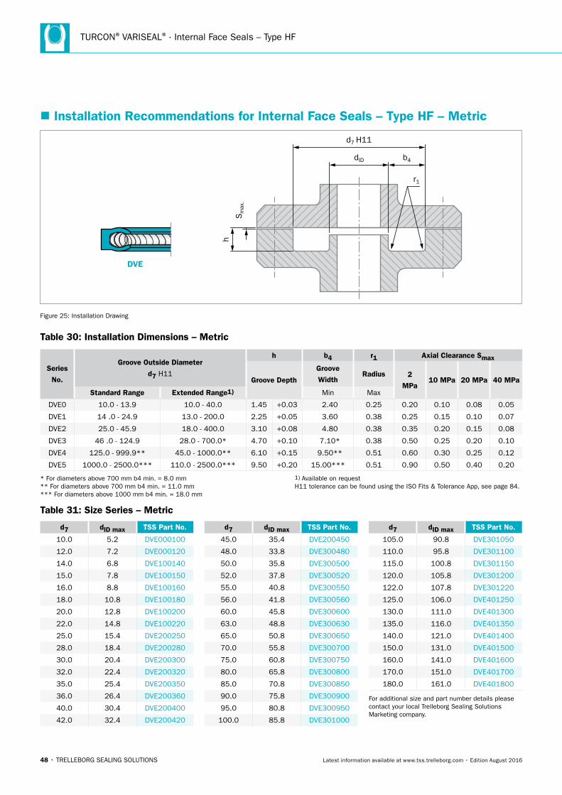
TURCON® VARISEAL® · Internal Face Seals – Type HF
48 • TRELLEBORG SEALING SOLUTIONS Latest information available at www.tss.trelleborg.com • Edition August 2016
� Installation Recommendations for Internal Face Seals – Type HF – Metric
DVE
Sm
ax.
h
d7 H11
dID b4
r1
Figure 25: Installation Drawing
Table 30: Installation Dimensions – Metric
Series
no.
Groove Outside Diameter
d7 H11
h b4 r1 Axial Clearance Smax
Groove Depth
Groove
Width Radius 2
MPa10 MPa 20 MPa 40 MPa
Standard Range extended Range1) Min Max
DVE0 10.0 - 13.9 10.0 - 40.0 1.45 +0.03 2.40 0.25 0.20 0.10 0.08 0.05
DVE1 14 .0 - 24.9 13.0 - 200.0 2.25 +0.05 3.60 0.38 0.25 0.15 0.10 0.07
DVE2 25.0 - 45.9 18.0 - 400.0 3.10 +0.08 4.80 0.38 0.35 0.20 0.15 0.08
DVE3 46 .0 - 124.9 28.0 - 700.0* 4.70 +0.10 7.10* 0.38 0.50 0.25 0.20 0.10
DVE4 125.0 - 999.9** 45.0 - 1000.0** 6.10 +0.15 9.50** 0.51 0.60 0.30 0.25 0.12
DVE5 1000.0 - 2500.0*** 110.0 - 2500.0*** 9.50 +0.20 15.00*** 0.51 0.90 0.50 0.40 0.20
* For diameters above 700 mm b4 min. = 8.0 mm 1) Available on request ** For diameters above 700 mm b4 min. = 11.0 mm H11 tolerance can be found using the ISO Fits & Tolerance App, see page 84. *** For diameters above 1000 mm b4 min. = 18.0 mm
Table 31: Size Series – Metric
d7 dID max TSS Part no.
10.0 5.2 DVE000100
12.0 7.2 DVE000120
14.0 6.8 DVE100140
15.0 7.8 DVE100150
16.0 8.8 DVE100160
18.0 10.8 DVE100180
20.0 12.8 DVE100200
22.0 14.8 DVE100220
25.0 15.4 DVE200250
28.0 18.4 DVE200280
30.0 20.4 DVE200300
32.0 22.4 DVE200320
35.0 25.4 DVE200350
36.0 26.4 DVE200360
40.0 30.4 DVE200400
42.0 32.4 DVE200420
d7 dID max TSS Part no.
45.0 35.4 DVE200450
48.0 33.8 DVE300480
50.0 35.8 DVE300500
52.0 37.8 DVE300520
55.0 40.8 DVE300550
56.0 41.8 DVE300560
60.0 45.8 DVE300600
63.0 48.8 DVE300630
65.0 50.8 DVE300650
70.0 55.8 DVE300700
75.0 60.8 DVE300750
80.0 65.8 DVE300800
85.0 70.8 DVE300850
90.0 75.8 DVE300900
95.0 80.8 DVE300950
100.0 85.8 DVE301000
d7 dID max TSS Part no.
105.0 90.8 DVE301050
110.0 95.8 DVE301100
115.0 100.8 DVE301150
120.0 105.8 DVE301200
122.0 107.8 DVE301220
125.0 106.0 DVE401250
130.0 111.0 DVE401300
135.0 116.0 DVE401350
140.0 121.0 DVE401400
150.0 131.0 DVE401500
160.0 141.0 DVE401600
170.0 151.0 DVE401700
180.0 161.0 DVE401800
For additional size and part number details please contact your local Trelleborg Sealing Solutions Marketing company.

Internal Face Seals – Type HF
TRELLEBORG SEALING SOLUTIONS • 49Latest information available at www.tss.trelleborg.com • Edition August 2016
Table 32: Part number Systems for Internal Face Seals – Metric
Article CodeCross-
SectionSize Class Seal Material
Spring Material
Spring Load
DVe Variseal HF
(Internal)
0 1.45
1 2.25
2 3.10
3 4.70
4 6.10
5 9.50
0xxxx Groove OD <1000 (dia x 10.0)
Xxxxx Groove OD >= 1000 (dia x 1.0)
- Industrial
A Aerospace
T01
MF1
MF4
MF6
T05
T07 See page 7
T12 for material
T24 description
T40
M79
Z48
Z80
S Stainless Steel
H Hastelloy
e Elgiloy
Standard load for each
design
H Heavy
ORDeRInG eXAMPLe 1
D V e 3 0 0 8 0 0 - T 0 5 S H
Design
Internal Face Seal
Variseal HF
Cross-Section
4.70 mm
Size
Leading indicator is 0 therefore 0800 size number represents a 80.0 mm Groove OD
Class
Industrial
Jacket Material
T05
Spring Material
Stainless steel
Heavy spring load
ORDeRInG eXAMPLe 2
D V e 5 X 1 2 0 0 - T 0 5 S H
Design
Internal Face Seal
Variseal HF
Cross-Section
9.50 mm
Size
Leading indicator is X therefore 1200 size number represents a 1200.0 mm Groove
OD
Class
Industrial
Jacket Material
T05
Spring Material
Stainless steel
Heavy spring load

TURCON® VARISEAL® · Internal Face Seals – Type HF
50 • TRELLEBORG SEALING SOLUTIONS Latest information available at www.tss.trelleborg.com • Edition August 2016
� Installation Recommendations for Internal Face Seals – Type HF – Inch
DVE
Sm
ax.
h
d7 H11
dID b4
r1
Figure 26: Installation Drawing
Table 33: Installation Dimensions – Inch
Series no.
h b4 r1 Axial Clearance Smax
Groove DepthGroove Width
Radius290 psi 1,450 psi 2,900 psi 5,800 psi
Min Max
DVE0 0.057 + 0.002 0.094 0.010 0.008 0.004 0.003 0.002
DVE1 0.089 + 0.002 0.141 0.015 0.010 0.006 0.004 0.003
DVE2 0.122 + 0.002 0.188 0.015 0.014 0.008 0.006 0.003
DVE3 0.186 + 0.002 0.281 0.015 0.020 0.010 0.008 0.004
DVE4 0.238 + 0.002 0.375 0.020 0.024 0.012 0.010 0.005
DVE5 0.374 + 0.004 0.591 0.020 0.030 0.015 0.012 0.006
H11 tolerance can be found using the ISO Fits & Tolerance App, see page 84.
Table 34: Standard Dash Sizes – Inch
d7 dID max TSS Part no.
0.500 0.313 DVe00M0120.625 0.438 DVe00M0140.750 0.563 DVE00M016
0.750 0.468 DVe10M1130.875 0.688 DVE00M018
0.875 0.593 DVe10M1150.875 0.500 DVE20M208
1.000 0.813 DVE00M020
1.000 0.718 DVe10M1171.000 0.625 DVE20M210
1.125 0.938 DVE00M022
1.125 0.843 DVe10M1191.125 0.750 DVE20M212
1.250 1.063 DVE00M024
1.250 0.968 DVE10M121
1.250 0.875 DVe20M214
d7 dID max TSS Part no.
1.250 0.688 DVE30M316
1.375 1.188 DVE00M026
1.375 1.093 DVE10M123
1.375 1.000 DVe20M2161.375 0.813 DVE30M318
1.500 1.313 DVE00M028
1.500 1.218 DVE10M125
1.500 1.125 DVe20M2181.500 0.938 DVE30M320
1.625 1.438 DVE00M029
1.625 1.343 DVE10M127
1.625 1.250 DVe20M2201.625 1.063 DVE30M322
1.750 1.563 DVE00M030
1.750 1.468 DVE10M129
1.750 1.375 DVe20M222
d7 dID max TSS Part no.
1.750 1.188 DVE30M324
1.875 1.688 DVE00M031
1.875 1.593 DVE10M131
1.875 1.500 DVe20M2231.875 1.313 DVE30M325
2.000 1.813 DVE00M032
2.000 1.718 DVE10M133
2.000 1.625 DVe20M2242.000 1.438 DVE30M326
2.000 1.250 DVE40M401
2.125 1.938 DVE00M033
2.125 1.843 DVE10M135
2.125 1.750 DVe20M2252.125 1.563 DVE30M327
2.125 1.375 DVE40M402
2.250 2.063 DVE00M034

Internal Face Seals – Type HF
TRELLEBORG SEALING SOLUTIONS • 51Latest information available at www.tss.trelleborg.com • Edition August 2016
d7 dID max TSS Part no.
2.250 1.968 DVE10M137
2.250 1.875 DVe20M2262.250 1.688 DVE30M328
2.250 1.500 DVE40M403
2.375 2.188 DVE00M035
2.375 2.093 DVE10M139
2.375 2.000 DVe20M2272.375 1.813 DVE30M329
2.375 1.625 DVE40M404
2.500 2.313 DVE00M036
2.500 2.218 DVE10M141
2.500 2.125 DVe20M2282.500 1.938 DVE30M330
2.500 1.750 DVE40M405
2.625 2.438 DVE00M037
2.625 2.343 DVE10M143
2.625 2.250 DVe20M2292.625 2.063 DVE30M331
2.625 1.875 DVE40M406
2.750 2.563 DVE00M038
2.750 2.468 DVE10M145
2.750 2.375 DVe20M2302.750 2.188 DVE30M332
2.750 2.000 DVE40M407
2.875 2.688 DVE00M039
2.875 2.593 DVE10M147
2.875 2.500 DVe20M2312.875 2.313 DVE30M333
2.875 2.125 DVE40M408
3.000 2.813 DVE00M040
3.000 2.718 DVE10M149
3.000 2.625 DVe20M2323.000 2.438 DVE30M334
3.000 2.250 DVE40M409
3.125 2.938 DVE00M041
3.125 2.750 DVe20M2333.125 2.563 DVE30M335
3.125 2.375 DVE40M410
3.250 2.875 DVe20M2343.250 2.688 DVE30M336
3.250 2.500 DVE40M411
3.375 3.188 DVE00M042
3.375 3.000 DVe20M2353.375 2.813 DVE30M337
3.375 2.625 DVE40M412
3.500 3.125 DVe20M2363.500 2.938 DVE30M338
3.500 2.750 DVE40M413
d7 dID max TSS Part no.
3.625 3.438 DVE00M043
3.625 3.250 DVE20M237
3.625 3.063 DVE30M339
3.625 2.875 DVE40M414
3.750 3.375 DVE20M238
3.750 3.188 DVe30M3403.750 3.000 DVE40M415
3.875 3.688 DVE00M044
3.875 3.500 DVE20M239
3.875 3.313 DVe30M3413.875 3.125 DVE40M416
4.000 3.625 DVE20M240
4.000 3.438 DVe30M3424.000 3.250 DVE40M417
4.125 3.938 DVE00M045
4.125 3.750 DVE20M241
4.125 3.563 DVe30M3434.125 3.375 DVE40M418
4.250 3.875 DVE20M242
4.250 3.688 DVE30M344
4.250 3.500 DVE40M419
4.375 4.000 DVE20M243
4.375 3.813 DVe30M3454.375 3.625 DVE40M420
4.500 4.125 DVE20M244
4.500 3.938 DVe30M3464.500 3.750 DVE40M421
4.625 4.250 DVE20M245
4.625 4.063 DVe30M3474.625 3.875 DVE40M422
4.750 4.375 DVE20M246
4.750 4.188 DVe30M3484.750 4.000 DVE40M423
4.875 4.500 DVE20M247
4.875 4.313 DVe30M3494.875 4.125 DVE40M424
5.000 4.625 DVE20M248
5.000 4.438 DVe30M3505.000 4.250 DVE40M425
5.250 4.875 DVE20M250
5.250 4.688 DVe30M3525.250 4.500 DVE40M427
5.500 5.125 DVE20M252
5.500 4.938 DVE30M354
5.500 4.750 DVE40M429
5.750 5.375 DVE20M254
5.750 5.188 DVE30M356
5.750 5.000 DVe40M431
d7 dID max TSS Part no.
6.000 5.625 DVE20M256
6.000 5.438 DVE30M358
6.000 5.250 DVe40M4336.250 5.875 DVE20M258
6.250 5.688 DVE30M360
6.250 5.500 DVe40M4356.500 6.125 DVE20M259
6.500 5.750 DVe40M4376.750 6.375 DVE20M260
6.750 6.000 DVe40M4387.000 6.625 DVE20M261
7.000 6.250 DVe40M4397.250 6.875 DVE20M262
7.250 6.500 DVe40M4407.500 7.125 DVE20M263
7.500 6.750 DVe40M4417.750 7.375 DVE20M264
7.750 7.000 DVe40M4428.000 7.625 DVE20M265
8.000 7.250 DVe40M4438.250 7.875 DVE20M266
8.250 7.500 DVe40M4448.500 8.125 DVE20M267
8.500 7.750 DVE40M445
9.000 8.625 DVE20M269
9.000 8.250 DVe40M4469.500 8.750 DVe40M447
10.000 9.250 DVe40M44810.500 9.750 DVe40M44911.000 10.250 DVe40M45011.500 10.750 DVe40M45112.000 11.250 DVe40M45212.500 11.750 DVe40M45313.000 12.250 DVe40M45413.500 12.750 DVe40M45514.000 13.250 DVe40M45614.500 13.750 DVe40M45715.000 14.250 DVe40M45815.500 14.750 DVe40M45916.000 15.250 DVe40M460
Figures in bold are preferred sizes. For additional size and part number details please contact your local Trelleborg Sealing Solutions Marketing company.

TURCON® VARISEAL® · Internal Face Seals – Type HF
52 • TRELLEBORG SEALING SOLUTIONS Latest information available at www.tss.trelleborg.com • Edition August 2016
Table 35: Part number Systems for Internal Face Seals – Inch
Article CodeCross-
SectionSize Class Seal Material
Spring Material
Spring Load
DVe Variseal HF
(Internal)
0 0.056
1 0.089
2 0.122
3 0.186
4 0.239
5 0.375
0Mxxx Dash #
Sxxxx Groove OD < 10.0 Inch (dia x 1000.0)
Lxxxx Groove OD >= 10.0 (dia x 100.0)
- Industrial
A Aerospace
T01
MF1
MF4
MF6
T05 See page 7
T07 for material
T12 description
T24
T40
M 79
Z48
Z80
S Stainless Steel
H Hastelloy
e Elgiloy
Standard load for each
design
H Heavy
ORDeRInG eXAMPLe 1
D V e 2 0 M 2 3 0 - T 0 5 S H
Design
Internal Face Seal
Variseal HF
Cross-Section
200 series (0.122 inch)
Size
Leading indicator is 0M therefore 230 is an inch dash number
Class
Industrial
Jacket Material
T05
Spring Material
Stainless steel
Heavy spring load
ORDeRInG eXAMPLe 2
D V e 3 S 3 4 0 0 - T 0 5 S H
Design
Internal Face Seal
Variseal HF
Cross-Section
300 series (0.186 inch)
Size
Leading indicator is S therefore 3400 size number represents a 3.400 inch groove OD
Class
Industrial
Jacket Material
T05
Spring Material
Stainless steel
Heavy spring load

Internal Face Seals – Type HF
TRELLEBORG SEALING SOLUTIONS • 53Latest information available at www.tss.trelleborg.com • Edition August 2016

TURCON®VARISEAL® · External Face Seals – Type HF
54 • TRELLEBORG SEALING SOLUTIONS Latest information available at www.tss.trelleborg.com • Edition August 2016
� Installation Recommendations for external Face Seals – Type HF – Metric
DVL
Sm
ax.
h
dOD
d8 b4
r1
P
h11
Figure 27: Installation Drawing
Table 36: Installation Dimensions – Metric
Series
number
Groove Inside Diameter
d8 h11h b4 r1 Axial Clearance Smax
Standard Range extended Range1)Groove
Depth
Groove Width Radius2 MPa
10
MPa
20
MPa
40
MPaMin Max
DVL0 3.0 - 9.9 3.0 - 40.0 1.45 +0.03 2.40 0.25 0.20 0.10 0.08 0.05
DVL1 10.0 - 19.9 8.0 - 200.0 2.25 +0.05 3.60 0.38 0.25 0.15 0.10 0.07
DVL2 20.0 - 39.9 12.0 - 400.0 3.10 +0.08 4.80 0.38 0.35 0.20 0.15 0.08
DVL3 40.0 - 119.9 20.0 - 700.0* 4.70 +0.10 7.10* 0.38 0.50 0.25 0.20 0.10
DVL4 120.0 - 999.9** 35.0 - 1600.0** 6.10 +0.15 9.50** 0.51 0.60 0.30 0.25 0.12
DVL5 1000.0 - 2500.9*** 80.0 - 2500.0*** 9.50 +0.20 15.00*** 0.51 0.90 0.50 0.40 0.20
* For diameters above 700 mm b4 min. = 8.0 mm 1) Available on request ** For diameters above 700 mm b4 min. = 11.0 mm h11 tolerance can be found using the ISO Fits & Tolerance App, see page 84. *** For diameters above 1000 mm b4 min. = 18.0 mm
Table 37: Size Series – Metric
d8 dOD Min TSS Part no.
4.0 8.8 DVL000040
5.0 9.8 DVL000050
6.0 10.8 DVL000060
8.0 12.8 DVL000080
10.0 17.2 DVL100100
12.0 19.2 DVL100120
14.0 21.2 DVL100140
15.0 22.2 DVL100150
16.0 23.2 DVL100160
18.0 25.2 DVL100180
20.0 29.6 DVL200200
22.0 31.6 DVL200220
25.0 34.6 DVL200250
28.0 37.6 DVL200280
30.0 39.6 DVL200300
32.0 41.6 DVL200320
d8 dOD Min TSS Part no.
35.0 44.6 DVL200350
36.0 45.6 DVL200360
40.0 54.2 DVL300400
42.0 56.2 DVL300420
45.0 59.2 DVL300450
48.0 62.2 DVL300480
50.0 64.2 DVL300500
52.0 66.2 DVL300520
55.0 69.2 DVL300550
56.0 70.2 DVL300560
60.0 74.2 DVL300600
63.0 77.2 DVL300630
65.0 79.2 DVL300650
70.0 84.2 DVL300700
75.0 89.2 DVL300750
80.0 94.2 DVL300800
d8 dOD Min TSS Part no.
85.0 99.2 DVL300850
90.0 104.2 DVL300900
95.0 109.2 DVL300950
100.0 114.2 DVL301000
105.0 119.2 DVL301050
110.0 124.2 DVL301100
115.0 129.2 DVL301150
120.0 139.0 DVL401200
125.0 144.0 DVL401250
130.0 149.0 DVL401300
135.0 154.0 DVL401350
140.0 159.0 DVL401400
150.0 169.0 DVL401500
160.0 179.0 DVL401600
170.0 189.0 DVL401700
180.0 199.00 DVL401800
For additional size and part number details please contact your local Trelleborg Sealing Solutions Marketing company.

External Face Seals – Type HF
TRELLEBORG SEALING SOLUTIONS • 55Latest information available at www.tss.trelleborg.com • Edition August 2016
Table 38: Part number System for external Face Seals – Metric
Article CodeCross-
SectionSize Class Seal Material Spring Material Spring Load
DVL Variseal HF (External)
0 1.451 2.252 3.103 4.704 6.105 9.50
0xxxx Groove ID <1000 (dia x 10.0)Xxxxx Groove ID >= 1000 (dia x 1.0)
- IndustrialA Aerospace
T01MF1MF4MF6T05T07 See page 7T24 for materialT40 descriptionM79Z48Z80
S Stainless SteelH Hastelloye Elgiloy
Standard load for each
design
H Heavy
ORDeRInG eXAMPLe 1
D V L 3 0 0 8 0 0 - T 0 5 S H
DesignExternal Face
SealVariseal HF
Cross-Section4.70 mm
SizeLeading indicator is 0 therefore 0800 size number represents a 80.0 mm Groove ID
ClassIndustrial
Jacket MaterialT05
Spring MaterialStainless steel
Heavy spring load
ORDeRInG eXAMPLe 2
D V L 5 X 1 2 0 0 - T 0 5 S H
DesignExternal Face
SealVariseal HF
Cross-Section9.50 mm
SizeLeading indicator is X therefore 1200 size number represents a
1200.0 mm Groove ID
ClassIndustrial
Jacket MaterialT05
Spring MaterialStainless steel
Heavy spring load

TURCON®VARISEAL® · External Face Seals – Type HF
56 • TRELLEBORG SEALING SOLUTIONS Latest information available at www.tss.trelleborg.com • Edition August 2016
� Installation Recommendations for external Face Seals – Type HF – Inch
DVL
Sm
ax.
h
dOD
d8 b4
r1
P
h11
Figure 28: Installation Drawing
Table 39: Installation Dimensions – Inch
Series number
h b4 r1 Axial Clearance Smax
Groove DepthGroove Width
Radius290 psi 1,450 psi 2,900 psi 5,800 psi
Min Max
DVL0 0.057 + 0.002 0.094 0.010 0.008 0.004 0.003 0.002DVL1 0.089 + 0.002 0.141 0.015 0.010 0.006 0.004 0.003DVL2 0.122 + 0.002 0.188 0.015 0.014 0.008 0.006 0.003DVL3 0.186 + 0.002 0.281 0.015 0.020 0.010 0.008 0.004
DVL4 0.238 + 0.002 0.375 0.020 0.024 0.012 0.010 0.005
DVL5 0.374 + 0.004 0.591 0.020 0.030 0.015 0.012 0.008
h11 tolerance can be found using the ISO Fits & Tolerance App, see page 84.
Table 40: Standard Dash Sizes – Inch
d8 dOD Min TSS Part no.
0.125 0.312 DVL00M006
0.187 0.375 DVL00M008
0.250 0.437 DVL00M010
0.375 0.562 DVL00M012
0.375 0.657 DVL10M110
0.500 0.687 DVL00M014
0.500 0.782 DVL10M112
0.625 0.812 DVL00M016
0.625 0.907 DVL10M114
0.625 1.000 DVL20M208
0.750 0.937 DVL00M018
0.750 1.032 DVL10M116
0.750 1.125 DVL20M210
0.875 1.062 DVL00M020
d8 dOD Min TSS Part no.
0.875 1.157 DVL10M118
0.875 1.250 DVL20M212
0.875 1.437 DVL30M316
1.000 1.187 DVL00M022
1.000 1.282 DVL10M120
1.000 1.375 DVL20M214
1.000 1.562 DVL30M318
1.125 1.312 DVL00M024
1.125 1.407 DVL10M122
1.125 1.500 DVL20M216
1.125 1.687 DVL30M320
1.250 1.437 DVL00M026
1.250 1.532 DVL10M124
1.250 1.625 DVL20M218
d8 dOD Min TSS Part no.
1.250 1.812 DVL30M322
1.375 1.562 DVL00M028
1.375 1.657 DVL10M126
1.375 1.750 DVL20M220
1.375 1.937 DVL30M324
1.500 1.687 DVL00M029
1.500 1.782 DVL10M128
1.500 1.875 DVL20M222
1.500 2.062 DVL30M325
1.500 2.250 DVL40M401
1.625 1.812 DVL00M030
1.625 1.907 DVL10M130
1.625 2.000 DVL20M223
1.625 2.187 DVL30M326

External Face Seals – Type HF
TRELLEBORG SEALING SOLUTIONS • 57Latest information available at www.tss.trelleborg.com • Edition August 2016
d8 dOD Min TSS Part no.
1.625 2.375 DVL40M402
1.750 1.937 DVL00M031
1.750 2.032 DVL10M132
1.750 2.125 DVL20M224
1.750 2.312 DVL30M327
1.750 2.500 DVL40M403
1.875 2.062 DVL00M032
1.875 2.157 DVL10M134
1.875 2.250 DVL20M225
1.875 2.437 DVL30M328
1.875 2.625 DVL40M404
2.000 2.187 DVL00M033
2.000 2.282 DVL10M136
2.000 2.375 DVL20M226
2.000 2.562 DVL30M329
2.000 2.750 DVL40M405
2.125 2.312 DVL00M034
2.125 2.407 DVL10M138
2.125 2.500 DVL20M227
2.125 2.687 DVL30M330
2.125 2.875 DVL40M406
2.250 2.437 DVL00M035
2.250 2.532 DVL10M140
2.250 2.625 DVL20M228
2.250 2.812 DVL30M331
2.250 3.000 DVL40M407
2.375 2.562 DVL00M036
2.375 2.657 DVL10M142
2.375 2.750 DVL20M229
2.375 2.937 DVL30M332
2.375 3.125 DVL40M408
2.500 2.687 DVL00M037
2.500 2.782 DVL10M144
2.500 2.875 DVL20M230
2.500 3.062 DVL30M333
2.500 3.250 DVL40M409
2.625 2.812 DVL00M038
2.625 2.907 DVL10M146
2.625 3.000 DVL20M231
2.625 3.187 DVL30M334
2.625 3.375 DVL40M410
2.750 2.937 DVL00M039
2.750 3.032 DVL10M148
2.750 3.125 DVL20M232
d8 dOD Min TSS Part no.
2.750 3.312 DVL30M335
2.750 3.500 DVL40M411
2.875 3.062 DVL00M040
2.875 3.157 DVL10M150
2.875 3.250 DVL20M233
2.875 3.437 DVL30M336
2.875 3.625 DVL40M412
3.000 3.187 DVL00M041
3.000 3.282 DVL10M151
3.000 3.375 DVL20M234
3.000 3.562 DVL30M337
3.000 3.750 DVL40M413
3.125 3.500 DVL20M235
3.125 3.687 DVL30M338
3.125 3.875 DVL40M414
3.250 3.437 DVL00M042
3.250 3.532 DVL10M152
3.250 3.625 DVL20M236
3.250 3.812 DVL30M339
3.250 4.000 DVL40M415
3.375 3.750 DVL20M237
3.375 3.937 DVL30M340
3.375 4.125 DVL40M416
3.500 3.687 DVL00M043
3.500 3.782 DVL10M153
3.500 3.875 DVL20M238
3.500 4.062 DVL30M341
3.500 4.250 DVL40M417
3.625 4.000 DVL20M239
3.625 4.187 DVL30M342
3.625 4.375 DVL40M418
3.750 3.937 DVL00M044
3.750 4.032 DVL10M154
3.750 4.125 DVL20M240
3.750 4.312 DVL30M343
3.750 4.500 DVL40M419
3.875 4.250 DVL20M241
3.875 4.437 DVL30M344
3.875 4.625 DVL40M420
4.000 4.187 DVL00M045
4.000 4.282 DVL10M155
4.000 4.375 DVL20M242
4.000 4.562 DVL30M345
4.000 4.750 DVL40M421
d8 dOD Min TSS Part no.
4.250 4.532 DVL10M156
4.250 4.625 DVL20M244
4.250 4.812 DVL30M347
4.250 5.000 DVL40M423
4.500 4.782 DVL10M157
4.500 4.875 DVL20M246
4.500 5.062 DVL30M349
4.500 5.250 DVL40M425
4.750 5.032 DVL10M158
4.750 5.125 DVL20M248
4.750 5.312 DVL30M351
4.750 5.500 DVL40M427
5.000 5.282 DVL10M159
5.000 5.375 DVL20M250
5.000 5.562 DVL30M353
5.000 5.750 DVL40M429
5.250 5.532 DVL10M160
5.250 5.625 DVL20M252
5.250 5.812 DVL30M355
5.250 6.000 DVL40M431
5.500 5.782 DVL10M161
5.500 5.875 DVL20M254
5.500 6.062 DVL30M357
5.500 6.250 DVL40M433
5.750 6.125 DVL20M256
5.750 6.312 DVL30M359
5.750 6.500 DVL40M435
6.000 6.375 DVL20M258
6.000 6.562 DVL30M361
6.000 6.750 DVL40M437
6.250 6.625 DVL20M259
6.250 6.812 DVL30M362
6.250 7.000 DVL40M438
6.500 6.875 DVL20M260
6.500 7.062 DVL30M363
6.500 7.250 DVL40M439
6.750 7.125 DVL20M261
6.750 7.312 DVL30M364
6.750 7.500 DVL40M440
7.000 7.375 DVL20M262
7.000 7.562 DVL30M365
7.000 7.750 DVL40M441
7.500 7.875 DVL20M264
7.500 8.062 DVL30M367

TURCON®VARISEAL® · External Face Seals – Type HF
58 • TRELLEBORG SEALING SOLUTIONS Latest information available at www.tss.trelleborg.com • Edition August 2016
d8 dOD Min TSS Part no.
7.500 8.250 DVL40M443
8.000 8.375 DVL20M266
8.000 8.562 DVL30M369
8.000 8.750 DVL40M445
9.000 9.375 DVL20M270
9.000 9.562 DVL30M373
9.000 9.750 DVL40M447
d8 dOD Min TSS Part no.
10.000 10.562 DVL30M377
10.000 10.750 DVL40M449
11.000 11.750 DVL40M451
12.000 12.750 DVL40M453
13.000 13.750 DVL40M455
14.000 14.750 DVL40M457
15.000 15.750 DVL40M459
Figures in bold are preferred sizes. For additional size and part number details please contact your local Trelleborg Sealing Solutions Marketing company.

External Face Seals – Type HF
TRELLEBORG SEALING SOLUTIONS • 59Latest information available at www.tss.trelleborg.com • Edition August 2016
Table 41: Part number System for external Face Seals – Inch
Article CodeCross-
SectionSize Class Seal Material Spring Material Spring Load
DVL Variseal HF (External)
0 0.0561 0.0892 0.1223 0.1864 0.2395 0.375
0Mxxx Dash #Sxxxx Groove ID < 10.0 Inch (dia x 1000.0)Lxxxx Groove ID >= 10.0 (dia x 100.0)
- IndustrialA Aerospace
T01MF1MF4MF6T05T07 See page 7T12 for material T24 descriptionT40M79Z48Z80
S Stainless SteelH Hastelloye Elgiloy
Standard load for each
design
H Heavy
ORDeRInG eXAMPLe 1
D V L 2 0 M 2 3 0 - T 0 5 S H
DesignExternal Face
SealVariseal HF
Cross-Section200 series
(0.122 inch)
SizeLeading indicator is
0M therefore 230 is an inch dash number
ClassIndustrial
Jacket MaterialT05
Spring MaterialStainless steel
Heavy spring load
ORDeRInG eXAMPLe 2
D V L 3 S 3 4 0 0 - T 0 5 S H
DesignExternal Face
SealVariseal HF
Cross-Section300 series
(0.186 inch)
SizeLeading indicator is S therefore 3400 size number represents a 3.400 inch Groove ID
ClassIndustrial
Jacket MaterialT05
Spring MaterialStainless steel
Heavy spring load

TURCON® VARISEAL® · Turcon® Roto Variseal®
60 • TRELLEBORG SEALING SOLUTIONS Latest information available at www.tss.trelleborg.com • Edition August 2016
� Turcon® Roto Variseal®
DeSCRIPTIOn
Turcon® Roto Variseal® is excellent in rotary, reciprocating and static applications, when there is a need to lock the seal in the groove.
The standard Variseal® for rotary applications, Turcon® Roto Variseal® is a single acting seal consisting of a U-shaped jacket and a V-shaped corrosion resistant spring.
Turcon® Roto Variseal® has a flanged heel, which prevents the seal from rotating in the groove and a short heavy dynamic lip that reduces friction. This gives a long service life and good scraping ability, even in media of high viscosity.
Turcon® Roto Variseal®
V-Shaped Spring
Retaining ange
P
Figure 29: Turcon® Roto Variseal®
AReAS OF APPLICATIOn
- Rotary shafts on general hydraulic applications
- Plastic injection molding machines
- Rotating and pivoting arms
- Gearbox shafts
TeCHnICAL DATA
Operating Pressure:
Maximum dynamic load: 20 MPa / 2,900 psi Maximum static load: 25 MPa / 3,626 psi
Speed: Reciprocating up to 10 m/s / 1,980 fpm, Rotating up to 2 m/s / 390 fpm
Temperature: -70 °C to +300 °C / -94 °F to +572 °F
Media compatibility:
Virtually all fluids, chemicals and gases
IMPORTAnT nOTe
The above data are maximum values and cannot be used at the same time, e. g. the maximum operating speed depends on material type, pressure, temperature and gap value. Temperature range also depends on the media.

Turcon® Roto Variseal®
TRELLEBORG SEALING SOLUTIONS • 61Latest information available at www.tss.trelleborg.com • Edition August 2016
FRICTIOnAL FORCe
Indicative values for frictional force are included in figure below. Frictional force is given as a function of sliding speed and operating pressure for a shaft diameter of 2 in / 50 mm at an oil temperature of +140 °F / +60 °C. The operating limits are lower at higher temperatures.
Indicative values for other shaft diameters can be calculated from the formula:
dP P50 x 50 mm
( ) [W]
(0)0 10 20 30
100
200
300
400
(1450) (2900) (4350)
1 m/s(3.28 ft/s)
0.5 m/s(1.64 ft/s)
0.25 m/s(0.82 ft/s)
0.15 m/s(0.50 ft/s)
Shaft 50 mm / 2 in60 ºC / 140 ºF
Pressure - MPa (psi)
Fric
tion
Pow
er (W
)
Figure 30: Frictional Force for Turcon® Roto Variseal®
The indicative values apply for constant operating conditions. Changes in these, such as pressure fluctuations or direction of rotation, can result in significantly higher frictional values.
APPLICATIOn LIMITS
The maximum operating limits for temperature, pressure and speed are dependent upon one another and therefore cannot all apply at the same time.
The lubrication properties of the media to be sealed and heat dissipation must also be taken into consideration.
The following PV values can be used as general guidelines:
Poor lubrication up to PV = 2 MPa x m/s (950 psi x ft/s)
Good lubrication up to PV = 5 MPa x m/s (2375 psi x ft/s)
Very good cooling up to PV = 8 MPa x m/s (3800 psi x ft/s)
These values are lower for diameters < 50 mm / 2 inches. Tests of these characteristics are recommended to establish application limits.
MATInG SuRFACe MATeRIALS
Sealing of applications with rotating movements require very good mating surfaces. A minimum hardness 55 HRC is recommended to a hardening depth of at least 0.3 mm / 0.01 inch.
Particular attention must be paid to coated surfaces and good heat dissipation through the coating is required.
Table 42: Permissible eccentricity for Turcon® Roto Variseal®
TSS Series no. Max. allowable deviation
mm
Max. allowable deviation
inch
TVM1 0.05 0.002
TVM2 0.10 0.004
TVM3 0.15 0.006
TVM4 0.20 0.008

TURCON® VARISEAL® · Turcon® Roto Variseal®
62 • TRELLEBORG SEALING SOLUTIONS Latest information available at www.tss.trelleborg.com • Edition August 2016
� Installation Recommendations for Roto Variseal® – Type TVM – Metric
blend radiusTVMd N
h9
h
Sm
ax.
d 1 H
9
30°
L1r1L2
d 2 H
10
k
Figure 31: Installation Drawing
Table 43: Installation Dimensions – Metric
Series no.
Shaft Diameter dn h9
d1 h d2 L1 L2 k r1 Radial Clearance Smax
Standard Range
extended Range
Groove Diameter
Groove Depth
Flange Diameter
Groove Width
Flange Groove Width
Lead-in Chamfer
Radius 2 MPa
10 MPa
20 MPa
H9 H10 Min Max
TVM1 5.0 - 19.9 5.0 - 200.0 dN + 5.0 2.50 dN + 9.0 3.6 0.85 +0/-0.10 0.8 0.38 0.25 0.15 0.10
TVM2 20.0 - 39.9 10.0 - 400.0 dN + 7.0 3.50 dN + 12.5 4.8 1.35 +0/-0.15 1.1 0.38 0.35 0.20 0.15
TVM3 40.0 - 399.9 20.0 - 700.0 dN + 10.5 5.25 dN + 17.5 7.1 1.80 +0/-0.20 1.4 0.38 0.50 0.25 0.20
TVM4 400.0 - 999.9 35.0 - 999.9 dN + 14.0 7.00 dN + 22.0 9.5 2.80 +0/-0.20 1.6 0.51 0.60 0.30 0.25
h9/H9 tolerance can be found using the ISO Fits & Tolerance App, see page 84.
Table 44: Size Series – Metric
dn d1 d2 TSS Part no.
5.0 10.0 14.0 TVM100050
6.0 11.0 15.0 TVM100060
8.0 13.0 17.0 TVM100080
10.0 15.0 19.0 TVM100100
12.0 17.0 21.0 TVM100120
14.0 19.0 23.0 TVM100140
15.0 20.0 24.0 TVM100150
16.0 21.0 25.0 TVM100160
18.0 23.0 27.0 TVM100180
20.0 27.0 32.5 TVM200200
22.0 29.0 34.5 TVM200220
25.0 32.0 37.5 TVM200250
28.0 35.0 40.5 TVM200280
30.0 37.0 42.5 TVM200300
32.0 39.0 44.5 TVM200320
35.0 42.0 47.5 TVM200350
36.0 43.0 48.5 TVM200360
40.0 50.5 57.5 TVM300400
dn d1 d2 TSS Part no.
42.0 52.5 59.5 TVM300420
45.0 55.5 62.5 TVM300450
48.0 58.5 65.5 TVM300480
50.0 60.5 67.5 TVM300500
52.0 62.5 69.5 TVM300520
55.0 65.5 72.5 TVM300550
56.0 66.5 73.5 TVM300560
60.0 70.5 77.5 TVM300600
63.0 73.5 80.5 TVM300630
65.0 75.5 82.5 TVM300650
70.0 80.5 87.5 TVM300700
75.0 85.5 92.5 TVM300750
80.0 90.5 97.5 TVM300800
85.0 95.5 102.5 TVM300850
90.0 100.5 107.5 TVM300900
95.0 105.5 112.5 TVM300950
100.0 110.5 117.5 TVM301000
105.0 115.5 122.5 TVM301050
dn d1 d2 TSS Part no.
110.0 120.5 127.5 TVM301100
115.0 125.5 132.5 TVM301150
120.0 130.5 137.5 TVM301200
125.0 135.5 142.5 TVM301250
130.0 140.5 147.5 TVM301300
135.0 145.5 152.5 TVM301350
140.0 150.5 157.5 TVM301400
150.0 160.5 167.5 TVM301500
160.0 170.5 177.5 TVM301600
170.0 180.5 187.5 TVM301700
180.0 190.5 197.5 TVM301800
190.0 200.5 207.5 TVM301900
200.0 210.5 217.5 TVM302000
210.0 220.5 227.5 TVM302100
220.0 230.5 237.5 TVM302200
230.0 240.5 247.5 TVM302300
240.0 250.5 257.5 TVM302400
250.0 260.5 267.5 TVM302500

Turcon® Roto Variseal®
TRELLEBORG SEALING SOLUTIONS • 63Latest information available at www.tss.trelleborg.com • Edition August 2016
Table 45: Part number System for Roto Variseal® – Metric
Article Code Cross-Section
Size Class Seal Material Spring Material Spring Load
TVM Roto Variseal 1 2.50
2 3.50
3 5.25
4 7.00
0xxxx Shaft dia. <1000 (dia x 10.0)
Xxxxx Shaft dia. >= 1000 (dia x 1.0)
- Industrial
A Aerospace
T01
MF1
MF4
MF6
T05
T07 See page 7
T12 for material
T24 description
T25
T40
M79
Z48
Z80
S Stainless Steel
H Hastelloy
e Elgiloy
Standard load for each
design
M Medium
R Hi Clean
ORDeRInG eXAMPLe 1
T V M 3 0 0 8 0 0 - T 4 0 S M
DesignRotary Seal
Roto Variseal
Cross-Section5.25 mm
SizeLeading indicator is 0 therefore 0800 size number represents a
80.0 mm shaft diameter
ClassIndustrial
Jacket MaterialT40
Spring MaterialStainless steel
Medium spring load
ORDeRInG eXAMPLe 2
T V M 4 X 1 2 0 0 - T 4 0 S M
DesignRotary Seal
Roto Variseal
Cross-Section7.00 mm
SizeLeading indicator is X therefore 1200 size number represents a
1200.0 mm shaft diameter
ClassIndustrial
Jacket MaterialT40
Spring MaterialStainless steel
Medium spring load

TURCON® VARISEAL® · Turcon® Roto Variseal®
64 • TRELLEBORG SEALING SOLUTIONS Latest information available at www.tss.trelleborg.com • Edition August 2016
� Installation Recommendations for Roto Variseal® – Type TVM – Inch
blend radiusTVMd N
h9
h
Sm
ax.
d 1 H
9
30°
L1r1L2
d 2 H
10
k
Figure 32: Installation Drawing
Table 46: Installation Dimensions – Inch
Series no.
Shaft Diameter dn h9
d1 d2 L1 L2 k r1 Radial Clearance Smax
Standard Range
extended Range
Groove Diameter
Flange Depth
Groove Width
Flange Groove Width
Lead-in Chamfer
Radius 2 MPa
10 MPa
20 MPa
H9 H10 Min Max
TVM1 0.187 - 0.749 0.187 - 8.000 dN + 0.197 dN + 0.354 0.141 0.033 +0/-0.004 0.031 0.015 0.010 0.006 0.004
TVM2 0.750 - 1.499 0.375 - 16.000 dN + 0.276 dN + 0.492 0.189 0.053 +0/-0.006 0.043 0.015 0.014 0.008 0.006
TVM3 1.500 - 14.999 0.750 - 28.000 dN + 0.413 dN + 0.689 0.280 0.071 +0/-0.008 0.055 0.015 0.020 0.010 0.008
TVM4 15.000 - 39.999 1.500 - 33.999 dN + 0.551 dN + 0.866 0.374 0.110 +0/-0.008 0.063 0.020 0.024 0.012 0.010
h9/H9 tolerance can be found using the ISO Fits & Tolerance App, see page 84.
Table 47: Size Series – Inch
dn d1 d2 TSS Part no.0.187 0.384 0.541 TVM1S01870.250 0.447 0.604 TVM1S02500.312 0.509 0.666 TVM1S03120.375 0.572 0.729 TVM1S03750.437 0.634 0.791 TVM1S04370.500 0.697 0.854 TVM1S05000.562 0.759 0.916 TVM1S05620.625 0.822 0.979 TVM1S06250.687 0.884 1.041 TVM1S06870.750 1.026 1.242 TVM2S07500.875 1.151 1.367 TVM2S08751.000 1.276 1.492 TVM2S10001.125 1.401 1.617 TVM2S11251.250 1.526 1.742 TVM2S12501.375 1.651 1.867 TVM2S13751.500 1.776 1.992 TVM2S15001.625 2.038 2.314 TVM3S16251.750 2.163 2.439 TVM3S1750
dn d1 d2 TSS Part no.1.875 2.288 2.564 TVM3S18752.000 2.413 2.689 TVM3S20002.125 2.538 2.814 TVM3S21252.250 2.663 2.939 TVM3S22502.375 2.788 3.064 TVM3S23752.500 2.913 3.189 TVM3S25002.625 3.038 3.314 TVM3S26252.750 3.163 3.439 TVM3S27502.875 3.288 3.564 TVM3S28753.000 3.413 3.689 TVM3S30003.125 3.538 3.814 TVM3S31253.250 3.663 3.939 TVM3S32503.375 3.788 4.064 TVM3S33753.500 3.913 4.189 TVM3S35003.625 4.038 4.314 TVM3S36253.750 4.163 4.439 TVM3S37503.875 4.288 4.564 TVM3S38754.000 4.413 4.689 TVM3S4000
dn d1 d2 TSS Part no.4.250 4.663 4.939 TVM3S42504.500 4.913 5.189 TVM3S45004.750 5.163 5.439 TVM3S47505.000 5.413 5.689 TVM3S50005.250 5.663 5.939 TVM3S52505.500 5.913 6.189 TVM3S55005.750 6.163 6.439 TVM3S57506.000 6.413 6.689 TVM3S60006.250 6.663 6.939 TVM3S62506.500 6.913 7.189 TVM3S65007.000 7.413 7.689 TVM3S70007.500 7.913 8.189 TVM3S75008.000 8.413 8.689 TVM3S80008.500 8.913 9.189 TVM3S85009.000 9.413 9.689 TVM3S90009.500 9.913 10.189 TVM3S9500
For additional size and part number details please contact your local Trelleborg Sealing Solutions Marketing company.

Turcon® Roto Variseal®
TRELLEBORG SEALING SOLUTIONS • 65Latest information available at www.tss.trelleborg.com • Edition August 2016
Table 48: Part number System for Roto Variseal® – Inch
Article Code Cross-Section
Size Class Seal Material Spring Material Spring Load
TVM Roto Variseal 1 0.098
2 0.138
3 0.207
4 0.276
Sxxxx Shaft dia. < 10.0 (dia x 1000.0)
Lxxxx Shaft dia. >= 10.0 (dia x 100.0)
- Industrial
A Aerospace
T01
MF1
MF4
MF6
T05
T07 See page 7
T12 for material
T24 description
T25
T40
M79
Z48
Z80
S Stainless Steel
H Hastelloy
e Elgiloy
Standard load for each
design
M Medium
R Hi Clean
ORDeRInG eXAMPLe 1
T V M 3 S 2 5 0 0 - T 4 0 S M
DesignRotary Seal
Roto Variseal
Cross-Section0.207 inch
SizeLeading indicator is S therefore 2500 size number represents a
2.500 inch shaft diameter
ClassIndustrial
Jacket MaterialT40
Spring MaterialStainless steel
Medium spring load
ORDeRInG eXAMPLe 2
T V M 4 L 1 1 5 0 - T 4 0 S M
DesignRotary Seal
Roto Variseal
Cross-Section0.276 inch
SizeLeading indicator is L therefore 1150 size number represents a
11.500 inch shaft diameter
ClassIndustrial
Jacket MaterialT40
Spring MaterialStainless steel
Medium spring load

66 • TRELLEBORG SEALING SOLUTIONS Latest information available at www.tss.trelleborg.com • Edition August 2016
Table 49: non-Catalog Standard Seal Design
Seal Application Technical Data
CommentsType
Type of Application
Maximum PressureWorking
TemperatureMaximum Speed
Sta
tic
Rec
ipro
catin
g
Rot
ary Dynamic Static
°C ° F
Recip. Rotary
MPa MPam/s fpm m/s fpm
Bar psi Bar psiW2S
C A C20 40 -70
to+300
-94to+572
15 1954 1.27 250
A wiper for those applications that require close control of friction or torque, or with wider hardware tolerance or eccentricities.
200 2900 400 5800
M2 with Ext Heel
C A B40 52 -70
to+300
-94to+572
15 1954 1.27 250
For greater extrusion resistance in applications with high pressures and/or temperatures.
400 5800 520 7500
W2 with Ext Heel
C A B40 52 -70
to+300
-94to+572
15 1954 1.27 250
Same as above but with a Slantcoil®
spring load. The Slantcoil spring handles more sideloading without taking a compression set.
400 5800 520 7500
MF
A - C n/a60 -100
to+200
-148to+392
n/a n/a
For static, slow rotary, or oscillating service sealing between two faces.
600 8702
WF
A - C n/a60 -150
to+200
-238to+392
n/a n/a
Same as above except with Slantcoil® use for greater flexibility in small diameters and crosssections.
600 8702
FM
B B A20 25 -70
to+300
-94to+572
15 1954 2.00 360
The flange on the O.D. of the seal is clamped axially in the housing, preventing rotation of the seal with the shaft.
200 2900 250 3626
FW
B B A20 25 -70
to+300
-94to+572
15 1954 2.00 360
The Slantcoil® spring provides closer control of torque values for low friction applications, and to reduce heat generation in general.
200 2900 250 3626
PM
B B A20 25 -54
to+204
-65to+400
15 1954 2.00 360
The O-Ring in the seal’s O.D. groove acts to prevent rotation with the shaft and to provide a positive static seal on the O.D.
200 2900 250 3626
PW
B B A20 25 -54
to+204
-65to+400
15 1954 2.00 360
For applications similar to above but require close control of friction or torque and for wider hardware tolerances or eccentricities.
200 2900 250 3626
CM
B B A20 25 -70
to+300
-94to+572
15 1954 2.00 360
A metal encased version of the Variseal PW. The metal provides the most reliable anti-rotation feature of all the rotary seals listed above.
200 2900 250 3626
CW
B B A20 25 -70
to+300
-94to+572
15 1954 2.00 360
Similar to Variseal CM, this design is energized with a Slantcoil spring which provides lower friction and closer control of torque values.
200 2900 250 3626

Turcon® Variseal®
TRELLEBORG SEALING SOLUTIONS • 67Latest information available at www.tss.trelleborg.com • Edition August 2016
TURCON®VARISEAL® · Special Types
� Special Types
TuRCOn® VARISeAL® HI-CLeAn
Turcon® Variseal® M2, M2S and Roto Variseal® are available with the spring groove filled with high temperature silicone. Extremely important in food and pharmaceutical processing, this minimizes the trapping of contaminants within the seal, making it easier to clean.
ADVAnTAGeS
- Significantly reduced dead space
- Can be sterilized easily
- Silicone compound increases sealing pressure
When ordering Variseal® Hi-Clean, change the last digit to the letter R.
TuRCOn® VARISeAL® WITH eXTenDeD HeeL
All Turcon® Variseal® types except the Turcon® Roto Variseal®
can be supplied with an extended heel as an alternative to existing O-Ring groove versions, with or without back-up ring (Figure 33 and Figure 35).
Standard O-Ringgroove withoutBack-up Ring
Extended HeelO-Ring groove withone Back-up Ring
L3
L1
P
P
Figure 33: Standard O-Ring groove with and without Back-up Ring
Silicone
Turcon® Variseal®
V-Shaped spring
P
Figure 34: Turcon® Variseal® Hi-Clean
TSS ARTICLe nuMBeR eXAMPLe
RVC2N0350 - T40SR
This version is also recommended for high-pressure applications or when the extrusion gap is larger than prescribed.
Standard Groove with standardTurcon® Variseal®
Extended Heel Groovewith extended heelTurcon® Variseal®
L3
L1
P
P
Figure 35: Standard Turcon® Variseal® and Turcon® Variseal® with extended heel

68 • TRELLEBORG SEALING SOLUTIONS Latest information available at www.tss.trelleborg.com • Edition August 2016
Special Types
Table 50: Groove Widths
Series no.Groove Width
mm (inch)
Rod Piston L1 L3RV_0 RV_A PV_0 PV_A 2.40 (0.094) 3.80 (0.149)
RV_1 RV_B PV_1 PV_B 3.60 (0.141) 4.65 (0.183)
RV_2 RV_C PV_2 PV_C 4.80 (0.188) 5.70 (0.235)
RV_3 RV_D PV_3 PV_D 7.10 (0.281) 8.50 (0.334)
RV_4 RV_E PV_4 PV_E 9.50 (0.375) 11.20 (0.475)
RV_5 RV_G PV_5 PV_G 15.00 (0.591) 20.00 (0.757)
Groove widths for standard grooves L1 and grooves with one Back-up Ring to L3.
A wide range of special and customized Variseal® designs are available. These may be slight modification to standard designs or a completely new configuration if required.
Table 51: Determining the TSS Article number
Turcon Variseal® Types
Standard Rod/Piston
extended Heel
Rod/Piston
Turcon Variseal® M2 RVA/PVA RVB/PVB
Turcon Variseal® M2S RVC/PVC RVD/PVD
Turcon Variseal® W2 RVJ/PVJ RVL/PVL
Turcon Variseal® H RVE/PVE RVF/PVF
When ordering the above seal types, use the first two letters of the standard TSS Article Number and replace the third letter as shown in table.
TSS ARTICLe nuMBeR eXAMPLe
RVB2N0350-T40SM
Rod/Face Seal High Pressure System Double Acting Piston Seal
Double DeckerConical SealTurcon® Variseal® withCorner Reinforcement
Low pressure seal to overcomelarge eccentricity
Sealing system for extreme high pressure Hi-Clean version
Can be adopted to most groove dimension
Variseal® produced in conical arrangement to seal against angled faces
Variseal® with high modulus corner reinforcement for high temperaturesin combination with high pressureor large extrusion gap
Figure 36: Customized Designs

TRELLEBORG SEALING SOLUTIONS • 69Latest information available at www.tss.trelleborg.com • Edition August 2016
TURCON®VARISEAL® · General Quality Criteria and Guidelines for Storage
� Storage InstructionsIf seals and bearings are stored, the following guidelines should be followed to optimize their storage life.
- Do not store seals in a deformed condition
- Store dry under normal atmospheric conditions (65% relative moisture ±10%)
- Ideal temperature for storage is between +5 °C and +25 °C (+41 °F and +77 °F)
- Exposure to heat, moisture, light, oxygen, ozone and liquids can have a detrimental effect on performance characteristics of some materials
- Direct contact with heat sources should be avoided
- Ensure seals cannot be physically damaged by anything within the storage area
- Keep in the original sealed packaging
� General Quality CriteriaThe cost-effective use of seals and bearings is highly influenced by the quality criteria applied in production. Seals and bearings from Trelleborg Sealing Solutions are continuously monitored according to strict quality standards from material acquisition through to delivery.
Certification of our production plants in accordance with international standards QS 9000/ISO 9000 meets the specific requirements for quality control and management of purchasing, production and marketing functions.
Our quality policy is consistently controlled by strict procedures and guidelines which are implemented within all strategic areas of the company.
All testing of materials and products is performed in accordance with accepted test standards and specifications, e.g. random sample testing in accordance with ISO 2859-1:2004-01 AQL 1,0 general inspection level II, normal inspection.
Inspection specifications correspond to standards applicable to individual product groups (e.g. for O-Rings: ISO 3601).Our sealing materials are produced free of chlorofluori-nated hydrocarbons and carcinogenic elements.
� Guidelines for the Storage of Polymer Products Based on ISO 2230
Many polymer products and components are stored for long periods of time before being put into service, so it is important they are stored in conditions that minimize unwanted changes in properties. Such changes may result from degradation, in which case they may include excessive hardening, softening, cracking, crazing and other surface effects. Other changes may be caused by deformation, contamination or mechanical damage.
PackagingUnless otherwise specified in the appropriate product specification, rubber products should be enclosed in individual sealed envelopes. The packaging should be carried out in an atmosphere in which the relative humidity is less than 70 %, or if polyurethanes are being packed, less than 65 %. Where there is serious risk of ingress of moisture (e.g. rubber-metal-bonded parts), aluminum foil/paper/polyethylene laminate or other similar means of protection should be used to ensure protection from ingress of moisture.
TemperatureThe storage temperature should be below +25 °C and the products should be stored away from direct sources of heat such as boilers, radiators and direct sunlight. If the storage temperature is below +15 °C, care should be exercised during handling of stored products, as they may have stiffened and have become susceptible to distortion if not handled carefully. HumidityThe relative humidity should be such that, given in the variations of temperature in storage, condensation does not occur. In all cases, the relative humidity of the atmosphere in storage should be less than 70 %, or if polyurethanes are being stored, less than 65 %.
LightRubber should be protected from light sources, in particular direct sunlight or intense light having a high ultra-violet content. It is advisable that any windows of storage rooms be covered with a red or orange coating or screen.
RadiationPrecautions should be taken to protect stored products from all sources of ionizing radiation likely to cause damage to the products.

70 • TRELLEBORG SEALING SOLUTIONS Latest information available at www.tss.trelleborg.com • Edition August 2016
General Quality Criteria and Guidelines for Storage
OzoneOzone has a particularly harmful effect on rubber. Storage rooms should not contain any equipment that is capable of generating ozone, such as mercury vapor lamps or high-voltage electrical equipment giving rise to electric sparks or electrical discharges. Combustion gases and organic vapors should also be excluded, as they may give rise to ozone via photo-chemical processes. When equipment such as a fork-lift truck is used to handle large rubber products, care needs to be taken to ensure this equipment is not a source of pollution that may affect the rubber. Combustion gases should be considered separately. While they are responsible for generating ground-level ozone, they may also contain unburned fuel which, by condensing on rubber products, can cause additional deterioration.
DeformationRubber should be stored free from tension, compressive stresses or other causes of deformation. Where products are packaged in a strain-free condition, they should be stored in their original packaging. In case of doubt, the manufacturer's advice should be sought. It is advisable that rings of large internal diameter are formed into three equal loops so as to avoid creasing or twisting. It is not possible to achieve this condition by forming just two loops.
Contact with liquids and semi-liquid materialsRubber should not be allowed to come into contact with liquid or semi-liquid materials (for example, petrol, greases, acids, disinfectants, cleaning fluids) or their vapors at any time during storage, unless these materials are by design an integral part of the product or the manufacturer's packaging. When rubber products are received coated with their operational media, they should be stored in this condition.
Contact with metalsCertain metals and their alloys (in particular, copper and manganese) are known to have harmful effects on some rubbers. Rubber should not be stored in contact with such metals except when bonded to them. They should be protected by wrapping in, or by separation with, a suitable material, e.g. paper or polyethylene.
Contact with dusting powderDusting powders should only be used for the packaging of rubber items in order to prevent adhesion. In such cases, the minimum quantity of powder to prevent adhesion should be used. Any powder used should be free from any constituent that would have a harmful effect on the rubber or the subsequent application of the rubber.
Contact between different productsContact between products made from rubbers of different compositions should be avoided. This includes products of the same type but differing in color.
Rubber-to-metal bonded productsThe metal part of rubber-to-metal bonded products should not come into contact with the rubber of other products. Preservative used on the metal should be of a type that it will not adversely affect the rubber or the bond to such an extent that it does not comply with the product specification.
Storage lifeThis is the maximum period of time that a rubber product, appropriately packaged, may be stored. After this time the product is regarded as unserviceable for the purposes for which it was originally manufactured. The storage life of a rubber product is influenced by its shape and size as well as its composition. Thick products usually undergo slower changes through degradation than thinner ones.
Initial storage periodThis is the maximum period, starting from the time of manufacture, for which a rubber product, appropriately packaged, may be stored under specified conditions before a sample needs to be inspected or re-tested.
extension storage periodThis is the period for which a rubber product, appropriately packaged, may be stored after the initial storage period, before further inspection and re-testing is necessary.
AssemblyThese are products or components containing more than one element, one or more of which is made of rubber. Generally it is not recommended to store elastomeric products in an assembled condition. If it is necessary to do so, the units should be checked more often. The inspection interval depends on the design and geometry of the components.
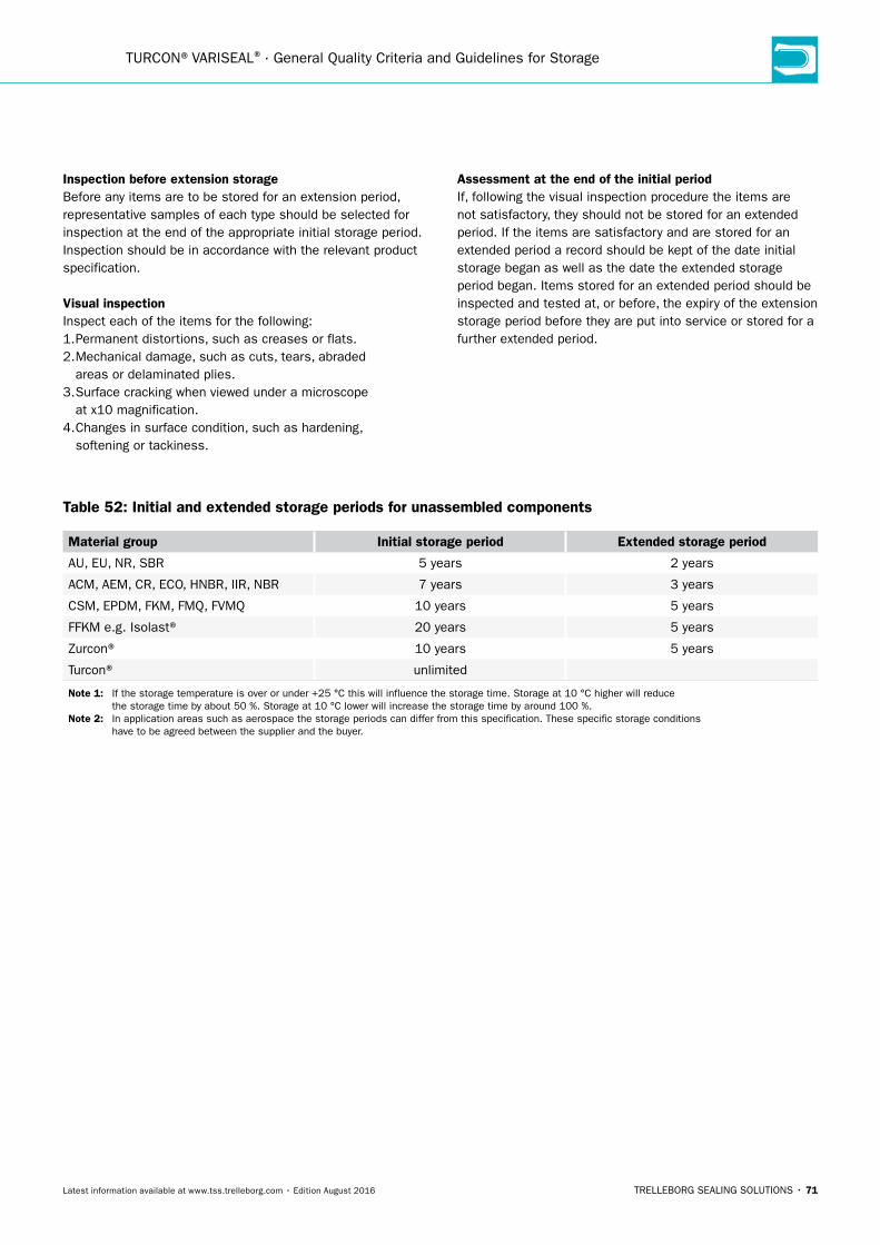
TRELLEBORG SEALING SOLUTIONS • 71Latest information available at www.tss.trelleborg.com • Edition August 2016
TURCON®VARISEAL® · General Quality Criteria and Guidelines for Storage
Inspection before extension storageBefore any items are to be stored for an extension period, representative samples of each type should be selected for inspection at the end of the appropriate initial storage period. Inspection should be in accordance with the relevant product specification.
Visual inspectionInspect each of the items for the following: 1. Permanent distortions, such as creases or flats. 2. Mechanical damage, such as cuts, tears, abraded areas or delaminated plies. 3. Surface cracking when viewed under a microscope at x10 magnification. 4. Changes in surface condition, such as hardening, softening or tackiness.
Assessment at the end of the initial periodIf, following the visual inspection procedure the items are not satisfactory, they should not be stored for an extended period. If the items are satisfactory and are stored for an extended period a record should be kept of the date initial storage began as well as the date the extended storage period began. Items stored for an extended period should be inspected and tested at, or before, the expiry of the extension storage period before they are put into service or stored for a further extended period.
Table 52: Initial and extended storage periods for unassembled components
Material group Initial storage period extended storage period
AU, EU, NR, SBR 5 years 2 years
ACM, AEM, CR, ECO, HNBR, IIR, NBR 7 years 3 years
CSM, EPDM, FKM, FMQ, FVMQ 10 years 5 years
FFKM e.g. Isolast® 20 years 5 years
Zurcon® 10 years 5 years
Turcon® unlimited
note 1: If the storage temperature is over or under +25 °C this will influence the storage time. Storage at 10 °C higher will reduce the storage time by about 50 %. Storage at 10 °C lower will increase the storage time by around 100 %. note 2: In application areas such as aerospace the storage periods can differ from this specification. These specific storage conditions have to be agreed between the supplier and the buyer.

72 • TRELLEBORG SEALING SOLUTIONS Latest information available at www.tss.trelleborg.com • Edition August 2016
Conversion Tables
Table 53: SI - Basic units
Measures units SymbolLength Metre m
Mass Kilogram kg
Time Second s
Electric current Ampere A
Temperature Kelvin K
Luminous intensity Candela cd
Amount of substance Mol mol
Table 54: Length
inch foot yard mm metre
1 inch = 0.0833 0.0278 25.4 0.0254
1 foot = 12 0.333 304.8 0.3048
1 yard = 36 3 914.4 0.9144
1 mm = 0.03937 0.0033 0.00109 0.001
1 metre = 39.37 3.2808 1.0936 1,000
Table 55: Torque
inch-
ounce
inch-
pound
foot-
pound
kg-
metre
newton-
metre
1 inch-ounce = 0.0625 0.0052 7.2x10⁻⁴ 7.06x10⁻³
1 inch-pound = 16 0.0833 1.152x10⁻² 0.1130
1 foot-pound = 192 12 0.1383 1.356
1 kg-metre = 1,388.7 86.796 7.233 9.80665
1 Newton-metre = 141.6 8.850 0.7375 0.1020
Table 56: Area
inch2 foot2 yard2 mm2 m2
1 inch2 = 0.0069 0.00077 645.16 6.45x10⁻⁴
1 foot2 = 144 0.111 92,903 0.0929
1 yard2 = 1,296 9 836,100 0.8361
1 mm2 = 0.0016 1.0764x10⁻⁵ 1.196x10⁻⁶ 10-6
1 m2 = 1,550 10.764 1.196 106
Table 57: Volume
inch3uS
quart
imp.
gallonfoot3
uS
gallonliter
1 inch3 = 0.0173 0.0036 0.00058 0.0043 0.0164
1 US quart = 57.75 0.2082 0.0334 0.25 0.9464
inch3uS
quart
imp.
gallonfoot3
uS
gallonliter
1 imp. gallon = 277 4.8 0.1604 1.2 4.546
1 foot3 = 1,728 29.922 6.23 7.48 28.317
1 US gallon = 231 4 0.8327 0.1337 3.785
1 liter = 61.024 1.0567 0.220 0.0353 0.264
Table 58: Temperature
°K (Kelvin) °C °F
°K = °C + 273.15 (°F - 459.67) 5/9
°C = °K - 273.15 (°F - 32) 5/9
°F = °K 9/5 - 459.67 °C 9/5 + 32
Table 59: Density
ounce/inch3 pound/foot3 g/cm3
1 ounce/inch3 = 108 1.73
1 pound/foot3 = 0.0092 0.016
1 g/cm3 = 0.578 62.43
Table 60: Force
newton (n) kilopond (kp)pound
force
1 Newton (N) = 0.10197 0.22481
1 kilopond (kp) = 9.80665 2.20463
1 pound force = 4.4482 0.45359
Table 61: Velocity (Speed)
foot/sfoot/
min
mile/
hourmetre/s km/hour
1 foot/s = 60 0.6818 0.3048 1.097
1 ft/min = 0.017 0.0114 0.00508 0.01829
1 mile/hour = 1.4667 88 0.447 1.609
1 metre/s = 3.280 196.848 2.237 3.6
1 km/h = 0.9113 54.68 0.6214 0.278
Table 62: Mass
ounce pound kg
1 ounce = 0.0625 0.0283
1 pound = 16 0.4536
1 kg = 35.274 2.2046
Table 63: Pressure
inch Hg psi atmosphere torr mm Hg bar MPa kg/cm2
1 inch Hg = 0.491 0.0334 25.4 25.4 0.0339 0.00339 0.0345
1 psi = 2.036 0.0680 51.715 51.715 0.0689 0.00689 0.0703
1 atmosphere = 29.921 14.696 760 760 1.0133 0.10133 1.0332
1 torr = 0.0394 0.0193 0.0013 1 0.0013 0.00013 0.00136
1 mm Hg = 0.0394 0.0193 0.0013 1 0.0013 0.00013 0.00136
1 bar = 29.53 14.504 0.987 749.87 749.87 0.1 1.020
1 MPa = 295.3 145.04 9.869 7498.7 7498.7 10 10.2
1 kg/cm2 = 28.950 14.22 0.968 735.35 735.35 0.980 0.098

Turcon® Variseal®
TRELLEBORG SEALING SOLUTIONS • 73Latest information available at www.tss.trelleborg.com • Edition August 2016

74 • TRELLEBORG SEALING SOLUTIONS Latest information available at www.tss.trelleborg.com • Edition August 2016
TURCON®VARISEAL® · Company Overview
OuR MISSIOn We will be the supply partner of first choice within our chosen markets, working globally through our local teams. We will build long-term partnerships with customers and suppliers by providing leading technology and excellent service. We are determined to be different.
SeALInG TeCHnOLOGyTrelleborg Sealing Solutions offers an outstandingly comprehensive sealing portfolio – a one-stop-shop providingthe best in elastomer, silicone, thermoplastic, PTFE and composite technologies; our solutions are featured in virtually every application conceivable within the aerospace, industrial and automotive industries.
A WORLDWIDe PReSenCeWe are uniquely placed to offer a dedicated design and development service for sealing solutions, globally servicing, supporting and supplying our customers through an unrivaledinternational network.
• Over 80 facilities worldwide• More than 20 manufacturing sites• Seven strategically positioned material
and development laboratories• Internationally linked design and
application centers
COMMITMenT – TO CuSTOMeRS’neeDS LOnG-TeRMThe aim of Trelleborg Sealing Solutions is to facilitate customers in achieving cost-effective, durable solutions that match their specific business requirements and needs. We are one of the world's foremost experts in polymer sealing technology. We develop, manufacture and supply safety-critical polymer- based precision seals, bearings and molded components.
Your Partner forSealing Technology“We build long term partnerships with customers and suppliers by providing leading technology and excellent service.”

TRELLEBORG SEALING SOLUTIONS • 75Latest information available at www.tss.trelleborg.com • Edition August 2016
Company Overview
THe TReLLeBORG GROuP
Trelleborg Sealing Solutions Key Industries
Automotive Food & Beverage, Chemical Processing
Marine
Machine Tools & Fluid Power
Off-Highway, Agriculture, Construction
Oil & Gas
Aerospace
Life Sciences and Pharmaceutical
Mining Alternative Energy
Trelleborg Coated SystemsLeading global supplier of unique customer solutions for polymer-coated fabrics deployed in a variety of industrial applications.
Trelleborg Offshore & ConstructionLeading global supplier of polymer-based critical solutions for deployment in highly demanding environments.
Trelleborg Wheel SystemsLeading global supplier of tires and complete wheels for agricultural and forestry machines, forklift trucks and other materials handling vehicles.
Trelleborg Industrial SolutionsMarket leader in such industrial application areas as hose systems, industrial antivibration solutions and selected industrial sealing systems.
Trelleborg Sealing SolutionsOne of the world’s leading developers, manufacturers and suppliers of precision seals. It supports its aerospace, industrial and automotive customers through over 20 production facilities and more than 50 marketing companies globally.

76 • TRELLEBORG SEALING SOLUTIONS Latest information available at www.tss.trelleborg.com • Edition August 2016
TURCON®VARISEAL® · Company Overview
OurGlobal Resources
2 R & D Centers 18 Marketing Companies 1 Logistics Centers SCM 6 Manufacturing Sites Damping Solutions 2 Automotive Hubs 4 Aerospace Hubs
8 Research & Development Centers
54 Marketing Companies
4 Logistics Centers
24 Manufacturing Sites
Damping Solutions
5 Automotive Hubs
8 Aerospace Hubs
OurGlobal Resources
Americas

TRELLEBORG SEALING SOLUTIONS • 77Latest information available at www.tss.trelleborg.com • Edition August 2016
How local is your global seal supplier?
www.global-but-local.com
Company Overview
1 R & D Centers 15 Marketing Companies 2 Logistics Centers SCM 4 Manufacturing Sites Damping Solutions 2 Automotive Hubs 2 Aerospace Hubs
europe
5 R & D Centers 21 Marketing Companies 1 Logistics Centers SCM 14 Manufacturing Sites Damping Solutions 1 Automotive Hubs 2 Aerospace Hubs
Asia
82worldwidelocations
5,300employees
More than
2,000proprietary material
formulations

78 • TRELLEBORG SEALING SOLUTIONS Latest information available at www.tss.trelleborg.com • Edition August 2016
TURCON®VARISEAL® · Company Overview
•AmericanVariseal•Busak+Shamban•DowtySeals•ChaseWalton•Forsheda•GNL•Impervia•Nordex•Orkot
•PalmerChenard•Polypac•SFMedical•Shamban•Silcofab•Silcotech•Skega•Stefa•Wills
WORLD RenOWneD nAMeS unITeDWe own many of the longest established and leading names within the seal industry. These include:
•Turcon® AQ Seal®
•D-A-SCompactSeal® •Turcon® Double Delta® •Turcon® excluder® •Turcon® Glyd Ring® T •Turcon® Hatseal•Zurcon® L-Cup® •Turcite® Slydring® •Turcite® B-Slydway®
•Turcon® Stepseal® 2K •V-Ring® •Turcon® Varilip® PDR •Turcon® Variseal® •Turcon® VL-Seal™ •Turcon® Wedgpak® •WillsRings® •Zurcon® Wynseal®
OuR PIOneeRInG PRODuCTSTrelleborg Sealing Solutions is pioneering and is continuously developing innovative products.
•HiMod® •Isolast® •Orkot® •Turcite®
•Turcon®
•Turel® •Zurcon®
PROPRIeTARy MATeRIALSOngoing development has yielded some of the most successful sealing and bearing materials available.
Products, Brandsand Materials
To design a solution for your specific needs, contact your local Trelleborg Sealing Solutions marketing company.
Decades of experience designing and manufacturing polymer solutions has led Trelleborg Sealing Solutions to develop, manufacture and supply a range of unique materials and proprietary product designs, many of which have become industry standards. Development is ongoing, ensuring that our solutions meet the changing needs of our customers, as well as the latest industry trends and regulations.

TRELLEBORG SEALING SOLUTIONS • 79Latest information available at www.tss.trelleborg.com • Edition August 2016
Company Overview

80 • TRELLEBORG SEALING SOLUTIONS Latest information available at www.tss.trelleborg.com • Edition August 2016
TURCON®VARISEAL® · Company Overview
Filmsand Animations
View atyouTube.com/trelleborgseals
View attss.trelleborg.com/
films
Online 24-7A range of films specific to different industries and products are available to view on the Trelleborg Sealing Solutions website or via YouTube.
SeeInG IS BeLIeVInG Complex sealing configurations can feature a large number of sealing elements. Trying to illustrate these on a 2-D page is difficult and can never properly show their function or characteristics. Trelleborg Sealing Solutions turned to the latest graphic technologies to produce 3-D animations of applications and typical sealing solutions for them.

TRELLEBORG SEALING SOLUTIONS • 81Latest information available at www.tss.trelleborg.com • Edition August 2016
Company Overview

82 • TRELLEBORG SEALING SOLUTIONS Latest information available at www.tss.trelleborg.com • Edition August 2016
+
–
+?
TURCON®VARISEAL® · Company Overview
OnLIne TOOLS MAKe LIFe eASIeRTrelleborg Sealing Solutions has developed a number of online tools that make the working life of an engineer specifying seals easier. All these industry-leading tools are available free-of-charge from the Trelleborg Sealing Solutions website at www.tss.trelleborg.com. To use these advanced services all you have to do is register on the Members Area.
There is also a continually increasing range of innovative engineering apps available for smartphones, both for iOS and Android devices. Just search for "Trelleborg" in the App Store or GooglePlay to find the tools to optimize your daily productivity.
O-Ring CalculatorAn industry-leading tool, the easy to use O-Ring calculator includes sizing capabilities, compression forces, design parameter recommendations and complete measurements.Results and comments may be printed, shared or filed as PDF.
Materials Search and Chemical Compatibility Check These two programs allow you to find out the compatibility of sealing materials to hundreds of different media and help identify the most suitable material for your application.
DigitalServices
Very good suitability
Good suitability
Limited suitability
Unsuitable
Insufficient information

TRELLEBORG SEALING SOLUTIONS • 83Latest information available at www.tss.trelleborg.com • Edition August 2016
Company Overview
Sealing Solutions ConfiguratorThe Sealing Solutions Configurator is the first tool of its kind offered by any seal supplier. It allows engineers to identify a proven sealing solution for their specific application in just four easy steps.
Versatile CAD Service The CAD download facility provides thousands of drawings of a wide range of seals. It gives the option of 2- or 3-dimensional files in a range of formats to suit most commonly used CAD systems.
Powerful electronic Catalog Search through over 100,000 seals by item number or their properties and access comprehensive and detailed information plus an interactive quote facility.
e-Learning on sealing technologyTrelleborg Sealing Solutions has a number of e-Learning modules available on several aspects of sealing technology.
For more information www.tss.trelleborg.com

84 • TRELLEBORG SEALING SOLUTIONS Latest information available at www.tss.trelleborg.com • Edition August 2016
TURCON®VARISEAL® · Company Overview
Mobile Appsand ServicesWe understand the needs of engineers on the go. Check out our latest mobile tools and apps, ranging from an O-Ring calculator to unit and hardness converters. Just search for "Trelleborg" in the App Store or Google Play to find the tools to optimize your daily productivity.
ISO Fits & Tolerances AppSimply enter the nominal
diameter and select the
tolerance classes for bore
and shaft to find the complete
ISO fits definition with all
relevant values including type
of fit, with handy graphs to
illustrate the classes by bore
and shaft.
Technical Glossary AppThis app provides definitions of more than 2,000 terms from the world of sealing technology and engineering.
Aerospace GrooveSelector AppThis app covers two of the most important SAE aerospace groove standards for hydraulic systems, AS4716 Rev B and AS5857 Rev A, making it really easy to find the size of grooves and hardware needed.
Installation Instructions AppVideos demonstrate thebest practice methods for installing seals, providing all relevant documentation within the interface, guiding you to a successful installation of Radial Oil Seals and Turcon® and Zurcon® rod and piston seals.
unit & HardnessConverter AppIntuitive and very easy to use,simply select the dimension and enter the value for conversion. The app offers a wide range of engineering and scientific units for each dimension.

TRELLEBORG SEALING SOLUTIONS • 85Latest information available at www.tss.trelleborg.com • Edition August 2016
Company Overview
HydraulicCylinder CalculatorQuickly calculate areas and volumes in cylinders, extraction and retraction forces, time velocity and outflow by entering the requisite dimensions and parameters of the cylinder. In compliance with ISO 3320, ISO 3321 and ISO 4393.
Tubing and Hose AppDeveloped specially for life sciences engineers, this app helps you to easily choose the correct tubing and hose based on material, pressure and dimensions, removing the need to search through catalogs.
Material Compability AppCross reference a wide variety of different materials with chemical environments to find the most effective compounds for your application. Select up to 20 materials at once to produce an easy to read compatibility chart with recommendations for use.
in the groove appOur in the groove magazine provides news, technical and product information on seals, as well as insights into the markets they are used in. The magazine is also available in print and as an interactive PDF.
For more information www.tss.trelleborg.com
O-Ring Calculator AppWhen a user enters installation specifications into the O-Ring Calculator app, such as the bore or rod/shaft diameter, the app quickly calculates O-Ring and housing dimensions in both metric and inch.
Available on theAPP STORe
MAny MORe APPS
available
Android App onGoogle Play

TURCON®VARISEAL® · Notes
86 • TRELLEBORG SEALING SOLUTIONS Latest information available at www.tss.trelleborg.com • Edition August 2016
Notes

www.Tss.Trelleborg.com
LocaL conTacTS
EuroPE
austria – Vienna (slovenia) +43 (0) 1 406 47 33 Belgium - Dion-Valmont (luxembourg)+32 (0) 10 22 57 50 Bulgaria – Sofia (azerbaijan, belarus, greece, romania, ukraine)+359 (0) 2 969 95 99 croatia – Zagreb (albania, bosnia and herzegovina, Macedonia, serbia, Montenegro)+385 (0) 1 24 56 387 czech republic - rakovnik (slovakia)+420 313 529 111Denmark – copenhagen +45 48 22 80 80 Finland – Vantaa (estonia, latvia)+358 (0) 207 12 13 50 France - Maisons-Laffitte +33 (0) 1 30 86 56 00
Germany - Stuttgart+49 (0) 711 7864 0 Hungary – Budaörs +36 (06) 23 50 21 21 Italy – Livorno +39 0586 22 6111 The netherlands - rotterdam +31 (0) 10 29 22 111 norway – oslo+47 22 64 60 80 Poland – Warsaw (lithuania)+48 (0) 22 863 30 11russia – Moscow +7 495 627 57 22 Spain – Madrid (portugal)+34 (0) 91 71057 30Sweden – Jönköping +46 (0) 36 34 15 00
Switzerland – crissier +41 (0) 21 631 41 11Turkey – Istanbul+90 216 569 73 00 united Kingdom - Solihull (eire)+44 (0) 121 744 1221
aerospace Hub Europe, north (uK and nordic countries) +44 (0) 121 744 1221aerospace Hub Europe, South & West (continental europe and Middle east) +33 (0) 1 30 86 56 00automotive Hub Europe +49 (0) 711 7864 0
aMErIcaS
americas regional +1 260 749 9631Brazil – São José dos campos+55 12 3932 7600canada central – Etobicoke, on+1 416 213 9444canada East – Montreal, Qc+1 514 284 1114canada West – Langley, Bc+1 604 539 0098Mexico - Mexico city+52 55 57 19 50 05
aSIa PacIFIc
asia Pacific regional+65 6 577 1778china – Hong Kong+852 2366 9165china – Shanghai+86 (0) 21 6145 1830India – Bangalore+91 (0) 80 3372 9000Japan – Tokyo+81 (0) 3 5633 8008Korea – Seoul+82 (0) 2 761 3471
uSa, Great Lakes - Fort Wayne, In+1 260 482 4050uSa, East - Mt. Juliet, Tn+1 615 800 8340uSa, Midwest - Schaumburg, IL+1 630 539 5500uSa, northern california - Fresno, ca+1 559 449 6070uSa, northwest - Portland, or+1 503 595 6565uSa, Southwest - Houston, TX+1 713 461 3495
aerospace Hub airframe+1 303 469 1357aerospace Hub Distribution & Engineering+1 260 749 9631aerospace Hub East +1 610 828 3209aerospace Hub West +1 310 371 1025automotive Hub north america+1 734 354 1250automotive Hub South america +55 12 3932 7600
Malaysia - Kuala Lumpur+60 (0) 3 90549266Taiwan – Taichung+886 4 2382 8886Vietnam – Ho chi Minh city+84 8 6288 6407Singapore and all other countries in South and East asia, australasia+65 6 577 1778
aerospace Hub china +86 (0) 21 6145 1830aerospace Hub Singapore +65 6 577 1778automotive Hub china +86 (0) 21 6145 1830automotive Hub India +91 (0) 80 3372 9200
aFrIca, cEnTraL aSIa anD MIDDLE EaST
Details available at www.tss.trelleborg.com

facebook.com/TrelleborgSealingSolutions
twitter.com/TrelleborgSeals
youtube.com/TrelleborgSeals
linkedin.com/company/trelleborg-sealing-solutions©
20
16
tre
llebo
rg g
roup
. at
tim
e of
pub
licat
ion
the
info
rmat
ion
cont
aine
d in
thi
s lit
erat
ure
is b
elie
ved
to b
e co
rrec
t an
d ac
cura
te.
99g
brVc
atae
0816
www.Tss.Trelleborg.com
Trelleborg is a world leader in engineered polymer solutions that seal, damp and protect critical applications in demanding environments. Its innovative engineered solutions accelerate performance for customers in a sustainable way. The Trelleborg Group has local presence in over 40 countries around the world.