turcon® rotary shaft seals · turcon ® rotary shaft seals busak+shamban edition november 2004...
TRANSCRIPT

Your Partner for Sealing Technology
Varilip® and Varilip® PDR
Turcon® RotaryShaft Seals

Turcon® Rotary Shaft Seals
Busak+Shamban Edition November 2004
Busak+Shamban forms part of Trelleborg SealingSolutions, a business area within Trelleborg AB and is amajor manufacturer and supplier of PTFE seals andengineered components to industries throughout theworld.
Manufacturing resources comprise 36 technology led centresdedicated to the production of sealing and bearing products.
Complementing these fully integrated productionfacilities, Busak+Shamban customer service is built onreal values - an in depth understanding of customerexpectations, an ability to quickly respond, an interactiveapproach to providing effective and appropriate solutionsand logistics support from over 30 marketing centresacross the globe.
Continuous improvement environments present in allfacilities reflect approvals to a wide range of industry andquality standards, including ISO9001-2000,FAA/CAA,AS9000, QS9000 and ISO14000.
The PTFE Rotary Seals product range is manufactured byTrelleborg Wills Polymers and the origins of this productwere established in 1981 for the design andmanufactureof specialised seals in a wide range of application fields.In addition, a standard product range has been availablesince 1991.
Our products serve coremarket sectors such as Industrial,Aerospace and Automotive in addition to specialisedniche markets.
We supply seals in quantities ranging from developmentparts and small production batches through to manyhundreds of thousands per year.
A major feature of our service is design flexibility.
Whilst we are more than capable of producingstraightforward seals for fitting in applications that mayhave already been designed around conventionalelastomeric seals, many of our customers contact us at anearly stage to design bespoke seals for applicationsspecific to their sealing needs.
This allows the opportunity to suggest weight and sizereduction, the possible inclusion of the seal into othercomponents and to put forward cost savings.
These important benefits can be obtained by contactingour designers before seal housing dimensions arefinalised.
We routinely use advanced non-linear finite elementanalysis on all new designs and employ 3D designtechniques where advantageous.
Comprehensive material testing facilities enable thecreation of in house FEA material models to accuratelydetermine shaft loadings and provide data for designcalculations.
Extensive rotary testing facilities are used for materialdevelopment, product development and customer testing.
Purpose built test rigs include special features such as airbearings and sophisticated torque measuring electronicsfor the development of low friction PTFE seals at speeds upto 20,000 rpm, well in excess of more typical rotary sealtest equipment.
Environmental cabinets enable all of the above rotarytesting to be carried out in the most extreme ofenvironmental conditions.

Turcon® Rotary Shaft Seals
1
Busak+ShambanEdition November 2004
Contents
Description 2. . . . . . . . . . . . . . . . . . . . . . . . . . . . . . . . . . . . . . . . . . . . . . . . . . . . . . . . . . . . . . . . . . . . . . . . . . . . . . . .
Product Range 3. . . . . . . . . . . . . . . . . . . . . . . . . . . . . . . . . . . . . . . . . . . . . . . . . . . . . . . . . . . . . . . . . . . . . . . . . . . . .
Materials 5. . . . . . . . . . . . . . . . . . . . . . . . . . . . . . . . . . . . . . . . . . . . . . . . . . . . . . . . . . . . . . . . . . . . . . . . . . . . . . . . .
Operating Parameters 7. . . . . . . . . . . . . . . . . . . . . . . . . . . . . . . . . . . . . . . . . . . . . . . . . . . . . . . . . . . . . . . . . . . . . .
Design Guidelines 10. . . . . . . . . . . . . . . . . . . . . . . . . . . . . . . . . . . . . . . . . . . . . . . . . . . . . . . . . . . . . . . . . . . . . . . . . .
Packaging 13. . . . . . . . . . . . . . . . . . . . . . . . . . . . . . . . . . . . . . . . . . . . . . . . . . . . . . . . . . . . . . . . . . . . . . . . . . . . . . . . .
Fitting Instructions 13. . . . . . . . . . . . . . . . . . . . . . . . . . . . . . . . . . . . . . . . . . . . . . . . . . . . . . . . . . . . . . . . . . . . . . . . . .
Installation Recommendations 15. . . . . . . . . . . . . . . . . . . . . . . . . . . . . . . . . . . . . . . . . . . . . . . . . . . . . . . . . . . . . . . .
Selection Guide 16. . . . . . . . . . . . . . . . . . . . . . . . . . . . . . . . . . . . . . . . . . . . . . . . . . . . . . . . . . . . . . . . . . . . . . . . . . . .
VarilipR Standard Sizes 17. . . . . . . . . . . . . . . . . . . . . . . . . . . . . . . . . . . . . . . . . . . . . . . . . . . . . . . . . . . . . . . . . . . . . .
Technical & Purchasing Questionnaire 23. . . . . . . . . . . . . . . . . . . . . . . . . . . . . . . . . . . . . . . . . . . . . . . . . . . . . . . . .
The information in this brochure is based on many decades of experience in the manufacture and application of sealingand bearing systems. However, unknown parameters and conditions may restrict general statements during usage. It isvital that Customers satisfy themselves as to the suitability of individual products throughadequate testing. For this reason,and due to the wide range of applications of our products, Busak+Shamban can accept no liability as to the suitability orcorrectness of our recommendations in individual cases. The application limits for pressure, temperature, speed andmedia given in this brochure aremaximum values determined in the laboratory. During practical applications it should beremembered that due to the interaction of the operating parameters, the maximum values must be set correspondinglylower.For exceptional operating conditions, please contact your Busak+Shamban representative.
This edition supersedes all previous brochures. This brochure, or any part thereof, may not be reproduced without ourpermission.
RAll trademarks are the property of Busak+Shamban.
e Busak+Shamban 2004. All rights reserved.
The turquoise colour is a registered trademark of Busak+Shamban.

Turcon® Rotary Shaft Seals
2
Busak+Shamban Edition November 2004
Description
TurconR rotary shaft seals extend the boundaries imposedby elastomer radial shaft seals, utilising advancedmaterials and design techniques to provide optimumsealing performance for each application. The outcomeis a superior sealing solution which retains a compact sealenvelope.
Standard elastomeric rotary shaft seals have a limitedapplication range with respect to temperature, surfacespeed, media compatibility, pressure or a combination ofthese due to the inherent limitations of the variouselastomer grades.
Furthermore they only have a limited suitability forapplications with inadequate lubrication.
TurconR rotary shaft seals are characterised in particularby the low friction and their stick-slip-free running, thusreducing the heat development and permitting higherperipheral speeds.
TurconR has the characteristic of inherent memory,whereby a distorted TurconR component will attempt torecover to the profile it had during the sintering cycle of itsmanufacturing process. This feature is used to provide thenecessary radial loading of the sealing lip onto the shaft,therefore negating the requirement for the energisingspring present in elastomeric seal designs.
Where required, seals can employ hydrodynamic sealing,which, in conjunction with mechanical retention of theTurconR in the seal body, gives exceptional sealperformance.

Turcon® Rotary Shaft Seals
3
Busak+ShambanEdition November 2004
Product Range
TurconR rotary shaft seals from Busak+Shamban areavailable in two product ranges: VarilipR and VarilipR
PDR. These ranges are designed to encompass standardsolutions to a wide range of applications and alsobespoke seal designs for applications where a standardproduct may not achieve desired levels of performance.
VarilipR
6 different types of VarilipR seal are available in a rangeof sizes suitable for DIN/ISO standard housing andgroove sizes. VarilipR seals use a plain lip and can thusbe used on shafts that rotate in either direction.
l D i iSeal Description
Type A
Type A - is a single lip seal suitable for use in standard industrial applications up to a pressure of0.5 MPa where an elastomer radial shaft seal would be unable to withstand the temperature,0.5 MPa where an elastomer radial shaft seal would be unable to withstand the temperature,friction, medium or poor lubrication. Allows sealing at surface speeds up to 30m/s with sufficientcooling and lubrication of the sealing lip.
Type B
Type B - is the preferred choice for applications in which a high seal integrity is demanded orh t i t d di t b l d Thi t ff ”b k ” li li t idwhere contaminated media are to be sealed. This type offers a ”back-up” sealing lip to provide
greater safety than the Type A.
Type C
Type C - can be used for applications involving higher pressures for which a simple elastomer radialh ft l l b id d D t i f t f th li li tshaft seal can no longer be considered. Due to reinforcement of the sealing lip, pressures up to2 MPa are possible, e.g. as pump, shaft or rotor seals.
Type D
Type D - can be subjected to pressure from both sides. Pressure differential of up to 0.1 MPa isi ibl Th ti f t diff t di i i l l i ibl Th d lipermissible. The separation of two different media using a single seal is possible. The second lip
can also take on the function of a wiper or dust lip.
Type E
Types E is similar to Type B but has an additional lip to prevent contaminants from reaching thesealing lips This enables an effective solution in environments where the seal may be exposed tosealing lips. This enables an effective solution in environments where the seal may be exposed toabrasive particles.
Type F
Types F is similar to type C but has an additional lip to prevent contaminants from reaching theli li Thi bl ff ti l ti i i t h th l b d t
yp yp p p gsealing lips. This enables an effective solution in environments where the seal may be exposed toabrasive particles.

Turcon® Rotary Shaft Seals
4
Busak+Shamban Edition November 2004
Varilip® PDRThese seals are individually designed to satisfy thedemands of specific applications and can thereforeaccommodate non-standard housing and shaft sizes.Typically they consist of a pressed ormachined casing anda mechanically retained TurconR element and in manyapplications they do not require the use of a gasket, thusimproving the chemical resistance of the seal system.Where required, VarilipR PDR seals can employ ahydrodynamic feature on the TurconR sealing lip. Thisprovides a positive displacement of the fluid as a result ofthe shaft rotation to give improved sealing in applicationswhere the shaft only rotates in a single direction. Thefeature also increases the flexibility of the lip which allowsa wider contact band between the TurconR lip and theshaft and helps to reduce shaft load and associated wear.
VarilipR PDR seals are produced as one of 3 basic designstyles, termed ’clamped’, ’crimped’ and ’single shell’, asillustrated in figures NO TAG, NO TAG and NO TAG.Axially split housings or housings with a poor surfacefinish or enlarged tolerance can be accommodated withthe use of a rubber OD cover or O-Ring.
VarilipR PDR’s relatively simple design and the nature ofthe machined or pressed casings promote the potentialfor integration of the seal into the surrounding hardware.Furthermore, the mechanical retention of the TurconR
provides a robust product which also eliminates thesometimes environmentally hazardous process ofbonding the TurconR to a metal or elastomer substrate.
Outer case
Elasto-mericgasket
Innercase
Sealant
Fluid
Machined or castmetal body
O-Ring
Fluid Fluid
Rubber cover
Single metalpressing
TurconR
dust lip
TurconR sealing lip TurconR sealing lipTurconR sealing lip
Figure 1 Clamped design Figure 2 Crimped design Figure 3 Single shell design
A selection of typical seal designs available using VarilipR
PDR technology is shown in Figure 4.Variants of these designs can be produced forapplications where it is beneficial to have the dynamicsealing surface at the housing, rather than the shaft.
Figure 4 Variants

Turcon® Rotary Shaft Seals
5
Busak+ShambanEdition November 2004
Materials
Sealing lipAn important factor for the proper function of rotationalseals is the material used for the sealing lip. For thisreason, Busak+Shamban has developed a range ofspecially modified materials on the basis of the provenTurconR materials. Particular importance is attached to
the optimisation of friction and wear properties, even athigh peripheral speeds.Table I gives the materials available for use in VarilipR
seals. Additional compounds have been developed forspecific applications and these are available if required.
Table I TurconR materials for VarilipR
Material,Applications,Properties
Code Operating temp.
°C
Mating surfacehardness
MPa
max.
Turcon® T25Standard material with exceptional wear and friction characteristics.F l b i t d d i
T25 -60 to +200 Min. 55 HRc
At low pressure and
2
For lubricated or dry running.Glass fibre, lubricantColour: Grey
At low pressure andup to 4 m/s,min.45 HRc
Turcon® T40For all lubricating and non lubricating fluids Used for medium hard
T40 -60 to +200 Min. 30 HRc 2For all lubricating and non-lubricating fluids. Used for medium hardshafts in applications where there is risk of shaft wear.C b fibCarbon fibreColour: Grey
TurconR T78Particularly good running behaviour permits use with dry running or poorlubrication and in conjunction with soft shaft surfaces eg stainless steel shafts
T78 -60 to +200 Min. 170 HB 0.2
lubrication and in conjunction with soft shaft surfaces eg stainless steel shaftsin food, pharmaceutical & chemical industries.Aromatic polymer.Colour: tan to dark brownOther TurconR materials are available by using the relevant material code when ordering.
Seal case
Standard VarilipR seals are available with a choice ofthree stainless steel materials for the seal case, as shownin table II.
In cases where repeated temperature cycling occurs withlarge variations in operating temperature, it is preferredthat the seal case materials are selected such that thecoefficient of linear expansion is similar to the material ofthe housing into which the seal will be assembled, tominimise the potential for loss of the interference betweenthe seal and the housing, and the resultant leakage orrelative movement.
Table III shows a selection of materials which can be usedfor VarilipR PDR seals to achieve themost compatible sealto housing interface. Additional materials specific toindividual applications may also be suitable, subject tosatisfactory process testing.
Highlighted materials are standard.
Table II Casing materials
Medium Material Code
Oils, greases,air/gases,water,vapour,solvents,foodstuffs
Stainless steelMaterial No. 1.4301AISI 304
1
Acids,caustics,
t
Acid-resistant stainless steelMaterial No. 1.4436 AISI 316
2,
seawaterAcid-resistant stainless steelMaterial No. 1.4571 AISI 316 Ti
3*)
*) Only for type A,C and D up to max. 90 mm outsidediameter.
Table III Housing materials
Housing Preferred SealCase
None-preferred SealCase
Steel, cast iron Low carbon steel Stainless steel or titanium
Aluminium alloy,die cast aluminium,magnesium
Aluminium alloy Stainless steel
Stainless steel Stainless steel Low carbon steel
Titanium Titanium Low carbon steel
Phosphor bronze Phosphor bronze Hastelloy C276

Turcon® Rotary Shaft Seals
6
Busak+Shamban Edition November 2004
Internal gasket
For VarilipR seals, the material for the internal gasketshould be specified with consideration of the fluidresistance and temperature regimes, in accordance withtable IV. VarilipR PDR seals can be designed with noelastomer content for maximum fluid compatibility. Incases where an elastomer is used, either as the internalgasket or as the sealing mechanism for the seal outsidediameter, a wide range of materials is available to suit thefluids, temperature ranges and other conditions, such asfood grade approval.
Table IV Materials for gasket elastomers
Medium Temperature Material Code
Air, water,oils, greases
Nitrile-Elastomer-30 to +110°C
NBR N
Air,water,vapour,foodstuffs,alcohol
Ethylene-propylene-elastomer-60 to +150°C
EPDM E
Air,water,oils,greases,solvents,acids,caustics
Fluoroelastomer-20 to +200°C
FKM V

Turcon® Rotary Shaft Seals
7
Busak+ShambanEdition November 2004
Operating Parameters
Speed
The graph in figure 5 is based upon DIN 3760 and showsthe limiting surface speed envelopes for variouselastomeric shaft seals. Results obtained from testingVarilipR PDR seals are superimposed. For generalguidance, VarilipR Type A is suitable up to 30 m/s, whilstTypes B, C, D, E & F should be limited to a maximum of15m/s. The operating speed directly impacts thetemperature generated by the seal and this is animportant factor when considering the requirements forthe sealing system. With specific designs, VarilipR PDRseals are in applications operating at surface speeds of108m/s and have been successfully tested in applicationsapproaching 140 m/s. The actual limiting speed will bedependant upon the temperature, pressure, media,lubrication properties, heat dissipation and the shaftcondition.
Shaft Diameter mm
80
70
60
50
40
30
20
10
00 40 80 120 160 200
SurfaceSpeedm/s
8000
7000
6000
5000
4000
3000
1000
2000
0
RPM
Figure 5 Surface speed as a function of shaftdiameter and RPM
Table V Surface speed
General Recommended maximum Surface Speed
VarilipR PDR (to date) 108 m/s
Fluoroelastomer 38 m/s
Silicone 38 m/s
Polyacrylic 22 m/s
Nitrile 12 m/s
Temperature
All TurconR seals are capable of outstanding high and,perhapsmore importantly, low temperature performancecompared to elastomeric materials. For VarilipR seals thetemperature limitation is controlled by the elastomermaterial selected for the internal gasket. VarilipR PDRseals can be designed without this limitation. Thetemperature capabilities given in figure 6 relate to thematerial itself and heat generation effects leading tohigher localised temperatures than the bulk media orambient level should be considered.
-100
Temperature
°C
-50
0
+50
+100
+150
+200
+250
+300
Figure 6 Maximum and minimum temperatures fordifferent materials
Table VI Temperature
General Recommended minimum/maximum Temperature
Filled PTFE -100 to +260°CFluoroelastomer -20 to +200°CSilicone -60 to +200°CPolyacrylic -20 to +150°CNitrile -40 to +135°CLeather -40 to +100°C

Turcon® Rotary Shaft Seals
8
Busak+Shamban Edition November 2004
Pressure
VarilipR Types A and B are suitable for pressures up to 0.5MPa. VarilipR Type C provides increased lip thickness tocater for pressures up to 2 MPa whilst VarilipR Type Dshould be limited to 0.1 MPa. VarilipR PDR seals can bespecifically designed to cater for higher pressures,depending upon other application considerations,particularly surface speed, temperature and liferequirement. VarilipR PDR seals are used in applicationswith short pressure spikes up to 6 MPa.
Pressure heavily influences the contact force between theTurconR lip and the shaft and consequently the heatgeneration. The following P x V values should only be usedas a general guideline for VarilipR.
For shaft diameters from 30mm to 170mm:
S Up to 1.5 (MPa x m/s) with good lubricationS Up to 3.0 (MPa xm/s) with good lubrication and coolingS Up to 10 (MPa x m/s) with very good lubrication andcooling or high temperature capability media.
For smaller shaft sizes these values should be reduced. ForPV values outside these values the use of a VarilipR PDRis recommended.
Fluid Resistance
TurconR consists of fully substituted carbon-carbon chainsand the carbon-carbon and carbon-fluorine bonds areamong the strongest known in organic chemistry. Theoutstanding physical and chemical properties of TurconR
can be attributed to these strong bonds. Within theconstraints of any elastomer used in the seal construction,for either the internal gasket or outer diameter sealing,VarilipR seals are resistant to mineral acids, bases,common organic fluids and solvents. They are alsounaffected by oxidation, ultraviolet radiation or ozonemaking them ideally suited for use in the chemical industryand applications requiring exposure to the atmosphere.VarilipR PDR can be designed without elastomer contentfor applications exposed to particularly aggressivemedia.A particular benefit is resistance to oil additives whichhave an adverse affect on many elastomers. UsingTurconR shaft seals allows the increased use of additivesand hence a longer oil service life.
Lubricant Starvation
TurconR shaft seals have the capability to run withoutlubricated for longer periods of time compared withelastomer shaft seals without adversely affecting theultimate life. This not only allows them to be used inapplications where the lubrication may be intermittent asa result of start up or other operating factors, but alsoallows their use as effective dirt, dust and powder seals.In one test VarilipR PDR seals were run dry for 100 hoursat 16 m/s and then continuously sealed oil.

Turcon® Rotary Shaft Seals
9
Busak+ShambanEdition November 2004
Power Consumption
Guide values for the torque and frictional powerconsumed by various types of VarilipR seal can bedetermined from figures 7 and8 . For specific applicationswhere achieving a certain level of power consumption iscritical to the operation of the equipment, VarilipR PDRseals can be designed and tested to demonstratecompliance with the requirement.
600
20
500
400
300
200
100
0151050
0.7 MPa0.5 MPa0.3 MPa
0.1 MPa
0 MPa
Speed m/s
Powerconsum
ptionP 5
0-W
Test carried out using a Type A VarilipR with T25 lip material
Typical nitrile shaft seal at 0MPa (160 W at 20m/s)
S
Figure 7 Power consumption on a 50 mm shaft
10.90.80.70.60.50.40.30.20.100 0.2 0.4 0.6 0.8
Type B and C, T25
Pressure MPa
Type A, T78
Type A, T25
Torque
M50
-Nm
Figure 8 Torque on a 50 mm shaft
Guide values for other shaft diameters (d) can beapproximated from the following formulae:
p≈p50 x (d/50) [W]
andM≈M50 x (d/50)2 [Nm]
Endurance
TurconR rotary shaft seals can provide an extendedservice life compared with elastomer shaft seals. As withany seal, the life of a VarilipR seal is very dependant uponthe specific operating parameters, but the followingexamples clearly illustrate the superior life achievablewiththese seals:
- A VarilipR PDR fitted as an engine crankshaft seal hascompleted over 1.75 million km (1.1 million miles)without leakage and both the shaft and seal were inexcellent condition after this length of service. This wasa known endurance vehicle and many seals are likelyto have significantly exceeded this result.
- A VarilipR PDR fitted to a rotary vane compressor hasbeen run for 23,000 hours without leakage and, moresignificantly for this particular application, hascompleted in excess of 500,000 start/stop cyclesbefore the test was terminated.
- VarilipR seals have been tested on aircraft flapactuators to a simulated 50,000 take-off and landingcycles without leakage.
- VarilipR seals fitted to pneumatic swivels runningunlubricated at 8 bar air pressure have exceededservice intervals of 13,000 hours.
- A VarilipR PDR has been run on a turbocharger fitted toa marine diesel engine. With surface speeds of108m/s, seal life in excess of 4500 hours has beenachieved.
Turcon® Rotary Shaft Seals
10
Busak+Shamban Edition November 2004
Design Guidelines
Housing
VarilipR seals require an interference fit with the housingbore to provide both adequate sealing of this interfaceand to ensure that the seal remains in place whensubjected to pressure, axial movement and inducedtorsion produced by the relative rotary motion of shaft tohousing bore. The bore should be machined with an H8diametric tolerance according to DIN 3760, ISO 6194/1and ISO16589/1as reproduced in table VII. VarilipR PDRseals can be designed with a coating on the outerdiameter, full rubber covering or anO-Ring fitted to eitherseal or housing bore to ensure good sealing of thisinterface. System design should also ensure that VarilipR
seals are not pushed into bores that may have beenpreviously scored by the assembly of another component,such as a bearing, selecting a larger seal outer diameterif necessary.
VarilipR PDR can also be designed to include discreteanti-rotation features, such as pins, lugs or axial clampingwhich, in conjunction with O-Ring sealing can be used incases where frequent seal assembly and disassemblymayotherwise damage the bore.
For VarilipR seals the bore should have a surface finishbetter than 10 μm Rmax, 6.3 μm Rz and 1.6 μm Ra. Incases where the housing bore is split resulting in an axialjoin crossing the seal outer diameter, and in cases wheremeeting these surface finish requirements is not possible,it is recommended that a proprietary sealant or adhesiveis used. Generally, VarilipR PDR can accommodatesurface finishes up to 3.2 μm Ra.
Table VII Housing installation data
Bore diameter [mm] Tolerance
Over To H8 [mm]
3 ⎯ 6 +.018 -0
6 10 + 022 06 ⎯ 10 +.022 -0
10 ⎯ 18 +.027 -0
18 ⎯ 30 +.033 -0
30 ⎯ 50 +.039 -0
50 ⎯ 80 +.046 -0
80 ⎯ 120 +.054 -0
120 ⎯ 180 +.063 -0
180 ⎯ 250 +.072 -0
250 ⎯ 315 +.081 -0
315 ⎯ 400 +.089 -0
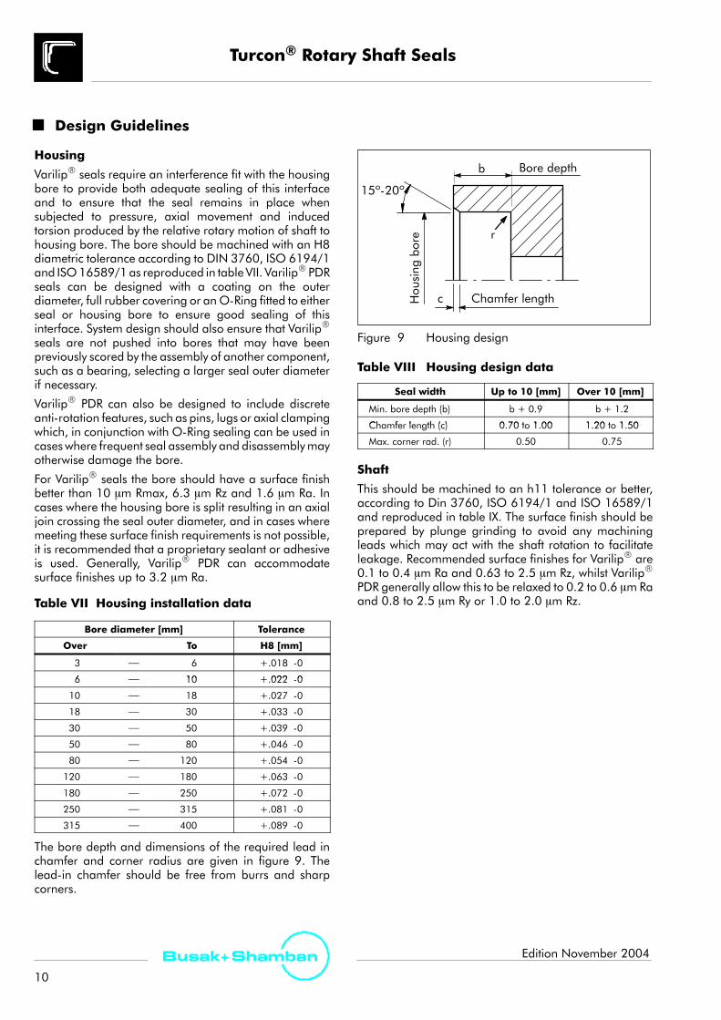
The bore depth and dimensions of the required lead inchamfer and corner radius are given in figure 9. Thelead-in chamfer should be free from burrs and sharpcorners.
15º-20º
Housing
bore
Chamfer length
Bore depth
r
b
c
Figure 9 Housing design
Table VIII Housing design data
Seal width Up to 10 [mm] Over 10 [mm]
Min. bore depth (b) b + 0.9 b + 1.2
Chamfer length (c) 0 70 to 1 00 1 20 to 1 50Chamfer length (c) 0.70 to 1.00 1.20 to 1.50
Max. corner rad. (r) 0.50 0.75
Shaft
This should be machined to an h11 tolerance or better,according to Din 3760, ISO 6194/1 and ISO 16589/1and reproduced in table IX. The surface finish should beprepared by plunge grinding to avoid any machiningleads which may act with the shaft rotation to facilitateleakage. Recommended surface finishes for VarilipR are0.1 to 0.4 μm Ra and 0.63 to 2.5 μm Rz, whilst VarilipR
PDR generally allow this to be relaxed to 0.2 to 0.6 μm Raand 0.8 to 2.5 μm Ry or 1.0 to 2.0 μm Rz.

Turcon® Rotary Shaft Seals
11
Busak+ShambanEdition November 2004
Table IX Shaft installation data
Shaft diameter [mm] Tolerance
Over To h11 [mm]
3 ⎯ 6 +0 -.075
6 10 +0 0906 ⎯ 10 +0 -.090
10 ⎯ 18 +0 -.110
18 ⎯ 30 +0 -.130
30 ⎯ 50 +0 -.160
50 ⎯ 80 +0 -.190
80 ⎯ 120 +0 -.220
120 ⎯ 180 +0 -.250
180 ⎯ 250 +0 -.290
250 ⎯ 315 +0 -.320
315 ⎯ 400 +0 -.360
A shaft hardness in excess of 55 HRc is generallyrecommended for VarilipR, although lower values arepermissible depending upon the pressure, speed andsealing lip material used (refer to materials section).
With specific design considerations, VarilipR PDR sealscan be run on much softer shafts, including SG Iron andlow carbon steels. Titanium shafts should be avoidedunless nitrided. Shafts with good chrome, nickel or zincplating, properly finishedare acceptable.Certain ceramiccoatings can also be used, although some grades havebeen proven to result in an aggressive wear of the sealinglip. In certain applications it may not be possible toprovide a shaft with the necessary hardness, surface finishand corrosion resistance. Fitting a wear sleeve onto theshaft can solve this problem such that if wear should occur,only the sleeve need then be replaced. The surface finishof the sleeve should be as outlined above andconsideration should be given to adequate heatdissipation and effective sealing of the interface betweenthe wear sleeve and the shaft.
When installing VarilipR seals, careful handling isimportant in order to avoid damaging the sealing lip. Ifthe seal is installed from the back, radii or lead-inchamfers must be machined on the end of the shaft, freefrom burrs, sharp corners or rough machining marks, asshown in figure 10. When installing the seal with the lipagainst the shaft end, a lead-in chamfer is requiredwhosesmallest diameter is smaller than the unstressed diameterof the sealing lip as shown in figure 11. Table X showsguide values for this. Preferable is the use of an installationcone, as shown in figure 12, where the seal can be fittedonto the cone before being located on the shaft to ensurecorrect orientation of the sealing lip.
It is recommended that as shallow an angle as practicalbe adopted within the range given, particularly forVarilipR Type C and F.
Table X Shaft lead in chamfer
d1 [mm] d1 - d3 [mm]
< 10 1.5
10 20 2 010 - 20 2.0
20 - 30 2.5
30 - 40 3.0
40 - 50 3.5
50 - 70 4.0
70 - 95 4.5
95 - 130 5.5
130 - 240 7.0
240 - 300 11.0
R min. 0.6
Figure 10 Installation of the sealing lip with the backto the shaft for pressurised application
d1 d3
30º max.
Figure 11 Shaft lead in chamfer
d1d3
max.0.4
Installation tool
15º-25º
Figure 12 Fitting the sealing lip using an installationtool

Turcon® Rotary Shaft Seals
12
Busak+Shamban Edition November 2004
Eccentricity
The graph in figure 13 is reproduced fromDIN 3760 andshows the maximum recommended operating envelopefor silicone, nitrile, polyacrylic and fluoroelastomer seals.VarilipR seals have a low interference with the shaft andto minimise the risk of leakage and increased wear rates,the levels of eccentricity should be kept within the limitsshown. In order to achieve a uniform radial load of thesealing lip on the shaft, the best possible coaxiality, orstatic offset, should be maintained between the housingbore and the shaft, as shown in figure 14. VarilipR PDRseals can, depending upon the application, be specificallydesigned to accommodate very high levels of eccentricity.Levels of 0.56mm TIR on a 67mm diameter shaft runningat 3000 rpm have successfully sealed for in excess of 500hours.
0
0.1
0.2
0.3
0.4
1000 2000 3000 4000 5000 6000
ShaftRunoutm
m
Shaft speed min-1
VMQ
NBR-ACM-FKM
VarilipR
Figure 13 Dynamic eccentricity capability
00
0.05
0.10
0.15
Coaxiality
mm
20
Shaft diameter mm
40 60 80 100 120 140 160
Figure 14 Coaxiality tolerance
Leakage expectation
Achieving absolute tightness between a sealingmechanism and a relatively moving surface is notpossible. It is important that the level of permissibleleakage for each application is determined as part of thespecification for the sealing solution. Generally a VarilipR
seal can be expected to provide at least the same level ofsealing as that achieved with a good quality elastomershaft seal, assuming all operating parameters and thecombination of themarewithin acceptable limits. VarilipR
PDR seals can be specifically designed to satisfy verystringent requirements on seal tightness and previousapplications have included cases where practically zeroleakage has been achieved.
Heat Generation Considerations
All VarilipR seals are designed to contact the shaft surfaceduring operation. The contact force between the sealinglip and the shaft will depend upon the seal design usedand the application details, but in all cases a temperatureincrease due to the presence of the seal can be expected.Where this increase is likely to be significant, either due tohigh pressures, surface speeds or poor lubrication, or dueto the surrounding equipment ormedia being particularlysensitive to temperature rises, consideration should begiven to methods of reducing the level of generated heat.This can be achieved through increases in localisedcooling, improved lubrication, efficient heat transfermechanismsand the use of a VarilipR PDR seal specificallydesigned to give low levels of heat generation.

Turcon® Rotary Shaft Seals
13
Busak+ShambanEdition November 2004
Shaft Wear
Whilst TurconR is inherently a low friction material, allVarilipR seals are designed to contact the shaft surfaceduring operation and a seal contact band will be evidentin the majority of applications. With correct sealspecification and operating conditions, shaft wear shouldbe limited to a light polishing, but factors such as overpressure, contamination, eccentricity and others canresult in more significant wear. As part of the systemdesign, consideration should be given to the level of shaftwear permissible within a set operating period andtherefore the benefits of measures intended to reduce therate of wear, such as shaft coatings, can be analysed inrelation to their additional cost.
Packaging
VarilipR seals are supplied wrapped together in shortstacks. VarilipR PDR have a higher level of diametricinterference between the sealing lip and the shaft and toease the assembly these seals are supplied on mandrelsto hold the sealing lip just below final shaft size.Alternative packaging arrangements, such as blisterpacking, long mandrels with multiple seals per mandrel,individually boxed, re-usable kanban boxes and othersare available on request for specific applications. Sealscan also be supplied on transport sleeves which have theassembly aid included in them, such that fitting the sealdoes not require a separate tool. This is of particularbenefit if the seal is to be supplied as a spares item andfitted in a number of remote locations.
Fitting Instructions
Investigation of premature failures has shown that asignificant proportion are as a result of inappropriateinstallation techniques. However, by observing thefollowing guidelines, such failures can be avoided:
S Assembly sleeves and fitting tools should be regularlychecked for signs of damage.
S When supplied on mandrels the seals should not beremoved from the mandrel until immediately prior tofitting. Seals supplied on cardboard mandrels shouldbe removed in the direction such that the spiral paperoverlay of the mandrel is not lifted.
S VarilipR seals may be pre-lubricated with the systemfluid prior to assembly if initial torque levels need to beminimised. VarilipR PDR seals should be assembled onto the shaft in an unlubricated (dry) condition to avoidcontamination of the hydrodynamic feature.
S Rubber coated seals should be assembled into thehousing using the system fluid as a lubricant on theirouter diameter.
S Care should be taken not to damage the outer diametersurface of the seal, whether this is coated in sealant,rubber covered or a plain metal case.
S Seals should be pressed squarely into the housing withthe pressing-in force applied as close as possible to theoutside diameter of the seal.
S If the seal contains a hydrodynamic feature on thesealing lip, ensure that it is correctly oriented in relationto the shaft’s direction of rotation.
S Normal practice is to install the seal with the lip facingthemedium to be sealed (the seal is reversed only whenit becomes more important to exclude a medium thanto retain it).
S Proprietary sealants or adhesives may be used forimproved sealing of the outer diameter in criticalapplications or for seal retention purposes. However,this should be avoided if the VarilipR PDR seal has beensupplied pre-coated with a sealant on the outerdiameter as chemical compatibility issues may result.
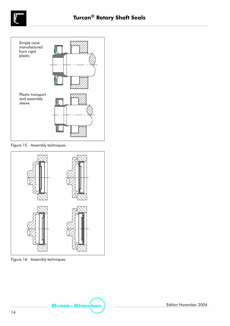
S VarilipR seals have widths designed in accordance withISO 6194/1 and ISO 16589 so as to ensure squareseating of the seal in the housing bore. Howevernarrower seals can be accommodated if assemblytooling, axial clamping or a retention circlip is used.Recommended tooling aids for satisfactory sealassembly are shown in figure 15 and 16.
Turcon® Rotary Shaft Seals
14
Busak+Shamban Edition November 2004
Plastic transportand assemblysleeve
Simple conemanufacturedfrom rigidplastic
Figure 15 Assembly techniques
Figure 16 Assembly techniques

Turcon® Rotary Shaft Seals
15
Busak+ShambanEdition November 2004
Installation Recommendations
The following diagrams show installation recommendationsin respect to seal retention under pressure conditions.
Post Installation Recommendations:S If painting, be sure to mask the seal. Avoid getting painton the lip, or the shaft where the lip rides. Also, maskany vents or drain holes so they will not becomeclogged. Be sure to remove masks before operatingunit.
S If paint is to be baked, or the mechanism is otherwisesubjected to heat, seals should not be heated totemperatures higher than their materials can tolerate.
S In cleaning or testing, do not subject seals to any fluidsor pressures other than those for which the seal hasbeen specified.
b
b1
20o
1.2 0.2±d1
h11
d2H8
R 0.5
Figure 17 Installation drawing for pressure up to 0.2 MPa
Pressure
d4
Figure 18 Installation for pressure from 0.2 MPaup to 2 MPa
Pressure
min.3
d5Pressure
Figure 19 Installation type D

Turcon® Rotary Shaft Seals
16
Busak+Shamban Edition November 2004
Selection Guide
If a bespoke, integrated or customised sealing solution is required, please complete the questionnaire on page 23 and send it to yourlocal Busak+Shamban sales office to allow a specific proposal to be prepared. If it is preferred to use a standard range product, pleasefollow the flow chart below to determine the product type recommended:
Yes
No
Does the shaft rotateonly in one direction ?
Is the fluid highlyviscous ?
Is surface speedgreater than 30 m/s ?
Maximumdifferential pressure ?
Back-up sealing liprequired ?
Contaminant liprequired ?
VarilipRType A
Maximumdifferential pressure ?
Is surface speedgreater than 15 m/s ?
VarilipRType D
No Hydrodynamic lip is recommended
Yes
Special lip design is recommendedYes
Contaminant liprequired ?
Is surface speedgreater than 15 m/s ?
Greater than 2.0 MPa Yes
No
Is surface speedgreater than 15 m/s ?
Contaminant liprequired ?
Yes
No
0.5 to 2.0 MPa
No Yes
VarilipR PDRComplete Questionnaire
on page 23
No
Yes
Less than0.1 MPa
Greater than0.1 MPa
VarilipRType C
VarilipRType F
YesNo
No
No
Yes Special lip design is recommended
VarilipRType E
VarilipRType B
Less than 0.5 MPa
No Yes
Note: This guide considers pressure and surface speed in isolation. Consideration should also be given to the PV value, as explained on page 9

Turcon® Rotary Shaft Seals
17
Busak+ShambanEdition November 2004
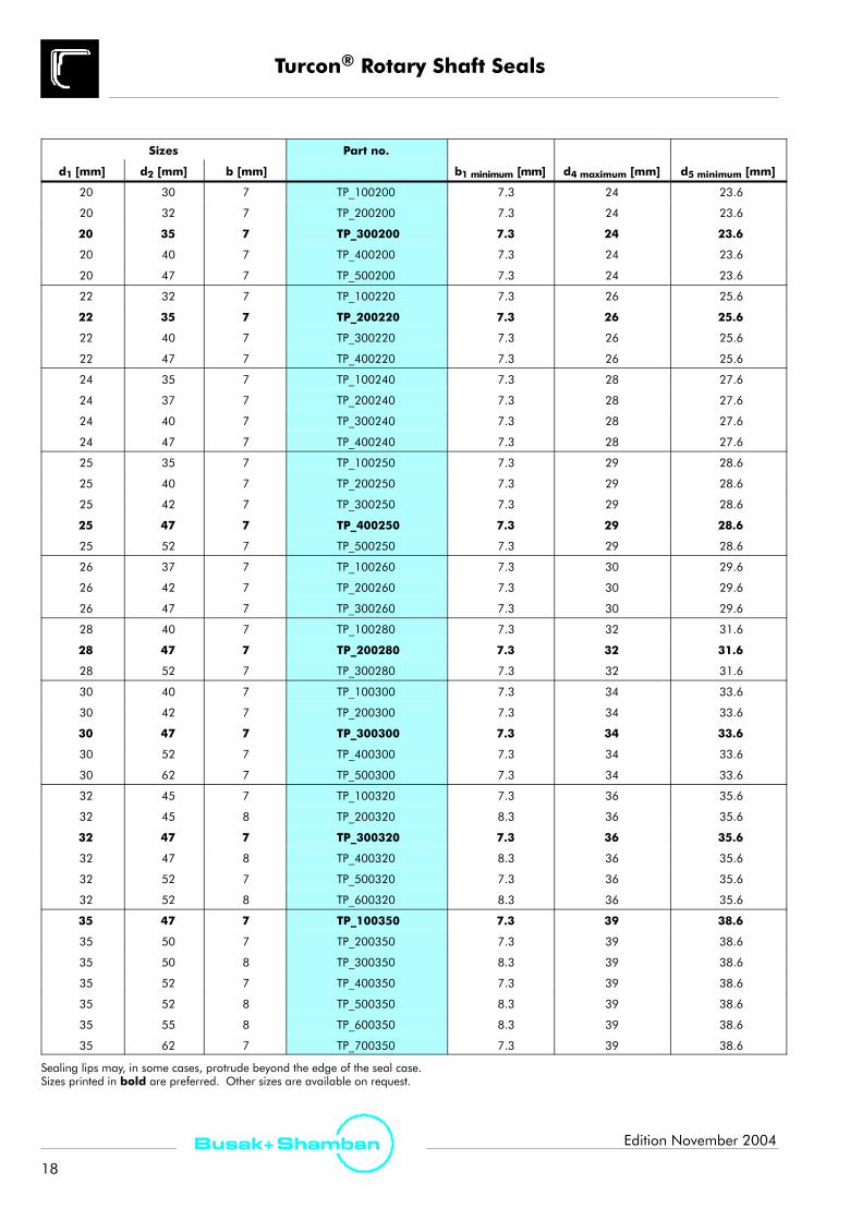
Table XI Varilip® Standard Sizes
Sizes Part no.
d1 [mm] d2 [mm] b [mm] b1 minimum [mm] d4 maximum [mm] d5 minimum [mm]
6 16 7 TP_100060 7.3 10 9.6
6 22 7 TP_200060 7.3 10 9.6
7 22 7 TP_100070 7.3 11 10.6
8 22 7 TP_100080 7.3 12 11.6
8 24 7 TP_200080 7.3 12 11.6
9 22 7 TP_100090 7.3 13 12.6
9 24 7 TP_200090 7.3 13 12.6
9 26 7 TP_300090 7.3 13 12.6
10 22 7 TP_100100 7.3 14 13.6
10 24 7 TP_200100 7.3 14 13.6
10 25 7 TP_300100 7.3 14 13.6
10 26 7 TP_400100 7.3 14 13.6
11 22 7 TP_100110 7.3 15 14.6
11 26 7 TP_200110 7.3 15 14.6
12 22 7 TP_100120 7.3 16 15.6
12 24 7 TP_200120 7.3 16 15.6
12 25 7 TP_300120 7.3 16 15.6
12 28 7 TP_400120 7.3 16 15.6
12 30 7 TP_500120 7.3 16 15.6
14 24 7 TP_100140 7.3 18 17.6
14 28 7 TP_200140 7.3 18 17.6
14 30 7 TP_300140 7.3 18 17.6
14 35 7 TP_400140 7.3 18 17.6
15 26 7 TP_100150 7.3 19 18.6
15 30 7 TP_200150 7.3 19 18.6
15 32 7 TP_300150 7.3 19 18.6
15 35 7 TP_400150 7.3 19 18.6
16 28 7 TP_100160 7.3 20 19.6
16 30 7 TP_200160 7.3 20 19.6
16 32 7 TP_300160 7.3 20 19.6
16 35 7 TP_400160 7.3 20 19.6
17 28 7 TP_100170 7.3 21 20.6
17 30 7 TP_200170 7.3 21 20.6
17 32 7 TP_300170 7.3 21 20.6
17 35 7 TP_400170 7.3 21 20.6
17 40 7 TP_500170 7.3 21 20.6
18 30 7 TP_100180 7.3 22 21.6
18 32 7 TP_200180 7.3 22 21.6
18 35 7 TP_300180 7.3 22 21.6
18 40 7 TP_400180 7.3 22 21.6
Sealing lips may, in some cases, protrude beyond the edge of the seal case.Sizes printed in bold are preferred. Other sizes are available on request.
Turcon® Rotary Shaft Seals
18
Busak+Shamban Edition November 2004
Sizes Part no.
d1 [mm] d2 [mm] b [mm] b1 minimum [mm] d4 maximum [mm] d5 minimum [mm]
20 30 7 TP_100200 7.3 24 23.6
20 32 7 TP_200200 7.3 24 23.6
20 35 7 TP_300200 7.3 24 23.6
20 40 7 TP_400200 7.3 24 23.6
20 47 7 TP_500200 7.3 24 23.6
22 32 7 TP_100220 7.3 26 25.6
22 35 7 TP_200220 7.3 26 25.6
22 40 7 TP_300220 7.3 26 25.6
22 47 7 TP_400220 7.3 26 25.6
24 35 7 TP_100240 7.3 28 27.6
24 37 7 TP_200240 7.3 28 27.6
24 40 7 TP_300240 7.3 28 27.6
24 47 7 TP_400240 7.3 28 27.6
25 35 7 TP_100250 7.3 29 28.6
25 40 7 TP_200250 7.3 29 28.6
25 42 7 TP_300250 7.3 29 28.6
25 47 7 TP_400250 7.3 29 28.6
25 52 7 TP_500250 7.3 29 28.6
26 37 7 TP_100260 7.3 30 29.6
26 42 7 TP_200260 7.3 30 29.6
26 47 7 TP_300260 7.3 30 29.6
28 40 7 TP_100280 7.3 32 31.6
28 47 7 TP_200280 7.3 32 31.6
28 52 7 TP_300280 7.3 32 31.6
30 40 7 TP_100300 7.3 34 33.6
30 42 7 TP_200300 7.3 34 33.6
30 47 7 TP_300300 7.3 34 33.6
30 52 7 TP_400300 7.3 34 33.6
30 62 7 TP_500300 7.3 34 33.6
32 45 7 TP_100320 7.3 36 35.6
32 45 8 TP_200320 8.3 36 35.6
32 47 7 TP_300320 7.3 36 35.6
32 47 8 TP_400320 8.3 36 35.6
32 52 7 TP_500320 7.3 36 35.6
32 52 8 TP_600320 8.3 36 35.6
35 47 7 TP_100350 7.3 39 38.6
35 50 7 TP_200350 7.3 39 38.6
35 50 8 TP_300350 8.3 39 38.6
35 52 7 TP_400350 7.3 39 38.6
35 52 8 TP_500350 8.3 39 38.6
35 55 8 TP_600350 8.3 39 38.6
35 62 7 TP_700350 7.3 39 38.6
Sealing lips may, in some cases, protrude beyond the edge of the seal case.Sizes printed in bold are preferred. Other sizes are available on request.

Turcon® Rotary Shaft Seals
19
Busak+ShambanEdition November 2004
Sizes Part no.
d1 [mm] d2 [mm] b [mm] b1 minimum [mm] d4 maximum [mm] d5 minimum [mm]
36 47 7 TP_100360 7.3 40 39.6
36 50 7 TP_200360 7.3 40 39.6
36 52 7 TP_300360 7.3 40 39.6
36 62 7 TP_400360 7.3 40 39.6
38 52 7 TP_100380 7.3 42 41.6
38 55 7 TP_200380 7.3 42 41.6
38 55 8 TP_300380 8.3 42 41.6
38 58 8 TP_400380 8.3 42 41.6
38 62 7 TP_500380 7.3 42 41.6
38 62 8 TP_600380 8.3 42 41.6
40 52 7 TP_100400 7.3 44 43.6
40 55 7 TP_200400 7.3 44 43.6
40 55 8 TP_300400 8.3 44 43.6
40 62 7 TP_400400 7.3 44 43.6
40 62 8 TP_500400 8.3 44 43.6
40 72 7 TP_600400 7.3 44 43.6
42 55 8 TP_100420 8.3 46 45.6
42 62 8 TP_200420 8.3 46 45.6
42 72 8 TP_300420 8.3 46 45.6
45 60 8 TP_100450 8.3 49 48.6
45 62 8 TP_200450 8.3 49 48.6
45 65 8 TP_300450 8.3 49 48.6
45 72 8 TP_400450 8.3 49 48.6
48 62 8 TP_100480 8.3 52 51.6
48 72 8 TP_200480 8.3 52 51.6
50 65 8 TP_100500 8.3 54 53.6
50 68 8 TP_200500 8.3 54 53.6
50 72 8 TP_300500 8.3 54 53.6
50 80 8 TP_400500 8.3 54 53.6
52 68 8 TP_100520 8.3 56 55.6
52 72 8 TP_200520 8.3 56 55.6
55 70 8 TP_100550 8.3 59 58.6
55 72 8 TP_200550 8.3 59 58.6
55 80 8 TP_300550 8.3 59 58.6
55 85 8 TP_400550 8.3 59 58.6
56 70 8 TP_100560 8.3 60 59.6
56 72 8 TP_200560 8.3 60 59.6
56 80 8 TP_300560 8.3 60 59.6
56 85 8 TP_400560 8.3 60 59.6
58 72 8 TP_100580 8.3 62 61.6
58 80 8 TP_200580 8.3 62 61.6
Sealing lips may, in some cases, protrude beyond the edge of the seal case.Sizes printed in bold are preferred. Other sizes are available on request.

Turcon® Rotary Shaft Seals
20
Busak+Shamban Edition November 2004
Sizes Part no.
d1 [mm] d2 [mm] b b1 minimum [mm] d4 maximum [mm] d5 minimum [mm]
60 75 8 TP_100600 8.3 64 63.6
60 80 8 TP_200600 8.3 64 63.6
60 85 8 TP_300600 8.3 64 63.6
60 90 8 TP_400600 8.3 64 63.6
62 85 10 TP_100620 10.3 68 66.4
62 90 10 TP_200620 10.3 68 66.4
63 85 10 TP_100630 10.3 69 67.4
63 90 10 TP_200630 10.3 69 67.4
65 85 10 TP_100650 10.3 71 69.4
65 90 10 TP_200650 10.3 71 69.4
65 100 10 TP_300650 10.3 71 69.4
68 90 10 TP_100680 10.3 74 72.4
68 100 10 TP_200680 10.3 74 72.4
70 90 10 TP_100700 10.3 76 74.4
70 95 10 TP_200700 10.3 76 74.4
70 100 10 TP_300700 10.3 76 74.4
72 95 10 TP_100720 10.3 78 76.4
72 100 10 TP_200720 10.3 78 76.4
75 95 10 TP_100750 10.3 81 79.4
75 100 10 TP_200750 10.3 81 79.4
78 100 10 TP_100780 10.3 84 82.4
80 100 10 TP_100800 10.3 86 84.4
80 110 10 TP_200800 10.3 86 84.4
85 110 12 TP_100850 12.4 91 89.4
85 120 12 TP_200850 12.4 91 89.4
90 110 12 TP_100900 12.4 96 94.4
90 120 12 TP_200900 12.4 96 94.4
95 120 12 TP_100950 12.4 101 99.4
95 125 12 TP_200950 12.4 101 99.4
100 120 12 TP_101000 12.4 106 104.4
100 125 12 TP_201000 12.4 106 104.4
100 130 12 TP_301000 12.4 106 104.4
105 130 12 TP_101050 12.4 111 109.4
105 140 12 TP_201050 12.4 111 109.4
110 130 12 TP_101100 12.4 116 114.4
110 140 12 TP_201100 12.4 116 114.4
115 140 12 TP_101150 12.4 121 119.4
115 150 12 TP_201150 12.4 121 119.4
120 150 12 TP_101200 12.4 126 124.4
120 160 12 TP_201200 12.4 126 124.4
125 150 12 TP_101250 12.4 131 129.4
125 160 12 TP_201250 12.4 131 129.4
Sealing lips may, in some cases, protrude beyond the edge of the seal case.Sizes printed in bold are preferred. Other sizes are available on request.

Turcon® Rotary Shaft Seals
21
Busak+ShambanEdition November 2004
Sizes Part no.
d1 [mm] d2 [mm] b [mm] b1 minimum [mm] d4 maximum [mm] d5 minimum [mm]
130 160 12 TP_101300 12.4 136 134.4
130 170 12 TP_201300 12.4 136 134.4
135 170 12 TP_101350 12.4 141 139.4
140 170 15 TP_101400 15.4 148 147.0
145 175 15 TP_101450 15.4 153 152.0
150 180 15 TP_101500 15.4 158 157.0
160 190 15 TP_101600 15.4 168 167.0
170 200 15 TP_101700 15.4 178 177.0
Sealing lips may, in some cases, protrude beyond the edge of the seal case.Sizes printed in bold are preferred. Other sizes are available on request.
Ordering example
VarilipR, type AShaft diameter d1 = 30 mmOutside diameterd2 = 47 mmWidth b = 7 mm
Table XI: Part no. TP_300300
The material is selected from Tables I, II and IV.
Material code - sealing lip
Type+cross sec.
Order-No. 0300 T25- 1
Material code - casing
Shaft-Ø x 10
A
Quality Index (Standard)
Lip Style (Standard)
0 V
Material code - gasket
TP 3
Order as: TPA300300-T251V
Type: A, B, C, D, E or F- refer to Product Range section
Cross Section: 1,2,3,4,5,6 or 7- refer to Table of Sizes
Lip Style: 0 (Std)Shaft x 10: Refer to Table of SizesQuality Index: - for standard partsLip Material: refer to Materials sectionCase Materal: refer to Materials sectionGasket Material: refer to Materials section

Turcon® Rotary Shaft Seals
22
Busak+Shamban Edition November 2004
For your notes:

Turcon® Rotary Shaft SealsTechnical and Purchasing Questionnaire
23Busak+ShambanEdition November 2004
Company name Agent/Salesman
Address Date
Company products
Application
Contacts Name Title Telephone Fax E-mail
Technical
Purchasing
Technical details Where available a sample or drawing of an existing seal is helpful but insufficient for a viable design to be produced unless accompanied by the followinginformation include installation drawing or scheme wherever possible.
Shaft
Diameter, with tolerances mm
Speed range Maximum: Typical: Minimum: RPM
Direction of rotation (when viewed from air/low pressure side) Bi-directionalAnti-clockwiseClockwise
Material and treatment
Surface roughness µm Rz µm Ra
Hardness HRc
Dynamic eccentricity mm TIR
Static housing-to-shaft offset mm centre to centre
Axial movement and frequency mm per
Shaft type at sealing pointHollow SleeveSolid Thickness mm
Housing
Diameter, with tolerances mm
Depth of recess mm
Speed range Maximum: Typical: Minimum: RPM
Direction of rotation (when viewed from air/low pressure side) Bi-directionalAnti-clockwiseClockwise
Housing type Axially split (split line will bisect seal OD) Homogeneous (no split line)
Material and treatment
Surface roughness µm Rz µm Rmax µm Ra
Hardness HRc
Environment
Type of fluid to be retained
Fluid level relative to shaft centreline
Shaft orientation during normal operation Horizontal Vertical
Any other media seal may contact Other:Water splashDust/dirt
Working temperature ºC
Maximum and minimum temperatures ºC
Maximum and minimum pressure differential Bar Cycle Rate
Maximum test pressure Bar
Is seal subject to pressure without shaft rotation Yes No
Purchasing details Note that this information will have an effect on the design solution offered. If actual data is unknown, please use estimations.
Drawing number (if available)
Would a test programme be necessary B+S Customer No Life Required
Type of release Aerospace Defence Industrial Specification
Annual usage Proportion we could expect
Rate of call off Supply commencement date
Prototype quantity Date prototypes required

99G
B/RA
D/T
URC
ON
/005
/110
4/1.
0
www.busakshamban.com
For further information:
Europe Telephone
AUSTRIA - Vienna +43 (1) 4 06 47 33
BELGIUM - Dion-Valmont +32 (10) 22 57 50
BULGARIA - Rousse +359 (82) 27 11 75
CZECH REPUBLIC - Rakovnik +420 (313) 52 91 11
DENMARK - Hillerød +45 (48) 22 80 80
FINLAND - Vantaa +358 (9) 8 25 61 10
FRANCE - Sartrouville +33 (1) 30 86 56 00
GERMANY - Stuttgart +49 (711) 7 86 40
HOLLAND - Barendrecht +31 (10) 2 92 21 11
ITALY - Livorno +39 (0586) 22 61 11
LUXEMBOURG - Dion-Valmont +32 (10) 22 57 50
NORWAY - Oslo +47 (22) 64 60 80
POLAND - Warsaw +48 (22) 8 63 30 11
SPAIN - Madrid +34 (91) 7 10 57 30
SWEDEN - Jönköping +46 (36 ) 34 15 00
SWITZERLAND - Crissier +41 (21) 6 31 41 11
UNITED KINGDOM - Solihull +44 (121) 7 44 12 21
For all other countries in Europe, Africa and the Near East,
please contact:
Busak+Shamban S.A. Division R.G. Export.
Route Sous-Riette 29, 1023 Crissier, Switzerland
Telephone +41 (21) 6 31 41 11, Fax +41 (21) 6 31 41 45
America Telephone
AMERICAS - Fort Wayne +1 (260) 7 49 96 31
BRAZIL - Sao Paulo +55 (11) 33 71 25 70
CANADA - Ontario +1 (416) 2 13 94 44
MEXICO - Mexico D.F. +52 (55) 53 85 05 86
USA, Midwest - Lombard +1 (630) 2 68 99 15
USA, South - N. Charleston +1 (843) 7 47 76 56
USA, Southwest - Houston +1 (713) 4 61 34 95
USA, West - Torrance +1 (310) 3 71 10 25
Asia Telephone
CHINA - Hong Kong +852 (2366) 91 65
INDIA - Bangalore +91 (80) 6 55 51 57
JAPAN - Tokyo +81 (35) 6 10 18 11
KOREA - Gyunggi-Do +82 (31) 3 86 32 83
TAIWAN - Taichung +886 (4) 23 58 00 82
SINGAPORE and all other
countries in Asia +65 (6293) 25 00
©Bu
sak+
Sham
ban
2004