turbine electrified energy management (teem) for enabling
TRANSCRIPT

American Institute of Aeronautics and Astronautics
1
Turbine Electrified Energy Management (TEEM) For Enabling More Efficient Engine Designs
Dennis. E. Culley1 and Jonathan L. Kratz2 NASA Glenn Research Center, Cleveland, Ohio, 44135
George L. Thomas3 N&R Engineering, Parma Heights, Ohio, 44142
NASA is investing in Electrified Aircraft Propulsion (EAP) research as part of an effort to assist industry in meeting the future needs of a global aviation market. The integration of electric machines into traditional turbine-based propulsion provides opportunities to change system architectures effecting radical improvements in propulsive efficiency. However, less consideration has been afforded to the utilization of these electrical machines to improve the thermal efficiency and performance of the gas turbine engine. Noting this deficit, a novel operability concept is proposed and is referred to as Turbine Electrified Energy Management (TEEM). The concept is a transient control technology that supplements the main fuel control for the suppression of the natural off-design dynamics associated with changes in engine operating state. Here the electric machines, used as engine actuators during the transient, add or extract torque from the engine shafts to maintain the speed-flow characteristics of steady-state design operation. This greatly reduces the need to maintain transient stall margin stack in the compressors, among other potential benefits. This paper demonstrates the feasibility of the concept in dynamic simulation using a Numerical Propulsion System Simulation (NPSS) engine model of a NASA hybrid electric propulsion concept known as the Parallel Hybrid Electric Turbofan (hFan).
Nomenclature BCPM = Battery Charge Power Mode CGT = Compact Gas Turbine EAP = Electrified Aircraft Propulsion FAA = Federal Aviation Administration FAR = Fuel to Air Ratio Fn = Net Thrust HEP = Hybrid Electric Propulsion hFan = Parallel Hybrid Electric Turbofan HPC = High Pressure Compressor HPM = High Pressure (spool) Motor HPS = High Pressure Spool I = Moment of inertia LPC = Low Pressure Compressor LPM = Low Pressure (spool) Motor LPS = Low Pressure Spool N1 = Speed of the low pressure spool N1c = Corrected Speed of the low pressure spool N2 = Speed of the high pressure spool NASA = National Aeronautics & Space Administration NPSS = Numerical Propulsion System Simulation 1 Research Engineer, 21000 Brookpark Rd., Cleveland OH, MS-77-1, Senior AIAA Member. 2 Research Engineer, 21000 Brookpark Rd., Cleveland OH, MS-77-1, AIAA Member. 3 Research Engineer, 6659 Pearl Rd. # 201, Cleveland, OH, AIAA Member.
Dow
nloa
ded
by N
ASA
GL
EN
N R
ESE
AR
CH
CE
NT
ER
on
July
16,
201
8 | h
ttp://
arc.
aiaa
.org
| D
OI:
10.
2514
/6.2
018-
4798
2018 Joint Propulsion Conference
July 9-11, 2018, Cincinnati, Ohio
10.2514/6.2018-4798
This material is declared a work of the U.S. Government and is not subject to copyright protection in the United States.
AIAA Propulsion and Energy Forum

American Institute of Aeronautics and Astronautics
2
ODM = On-Demand Mobility OPR = Overall Pressure Ratio P = Power PR = Pressure Ratio SM = Stall Margin t = time T3 = Total temperature at the exit of the high pressure compressor T4 = Total temperature at the inlet of the high pressure turbine TEEM = Turbine Electrified Energy Management TSFC = Thrust Specific Fuel Consumption VBV = Variable Bleed Valve Wc = Corrected Mass Flow Rate Wf = Fuel Flow Rate ZSPM = Zero Sum Power Mode ω = Angular velocity ωdes = Desired angular velocity
I. Introduction lectrified Aircraft Propulsion (EAP) is a promising path forward for future commercial air transport. The electrification of these systems will come in various forms. In general, small aircraft flying short distances with
small payloads, such as On Demand Mobility (ODM)1, will not use a turbine engine. ODM vehicles are envisioned to be fully electric with their propulsive power derived from onboard energy storage devices such as batteries. However, for larger air vehicles, electrical energy storage technology will simply not have the energy density necessary for the foreseeable future to outperform a fuel-driven turbine engine. This is evident by the system studies2 that have been completed, some of which are summarized in Table 1.
The electrified propulsion architectures listed in Table 1 are all hybrids and therefore include a gas turbine engine. There is a variety of possible powertrain options for electrified propulsion systems and they generally fall into two categories3: turboelectric and hybrid-electric, referring to the source of power. Turboelectric configurations store all energy in the form of fuel but generate electrical power for motor-driven propulsors, which are typically located some distance away. A partially turboelectric variant implies that the turbine engine also produces mechanical thrust in the traditional sense, as well as sourcing electrical power for propulsion. A hybrid system, in contrast, will store significant propulsive energy within an energy storage device, such as a battery, in addition to the fuel. Hybrid systems fall into two major subcategories, parallel and series, referring to the means of propulsion. Parallel hybrid variants entail thrust-producing turbomachinery with electrical power augmentation. The series hybrid variant describes electric motor-driven propulsion whose source of power is a turboelectric system augmented with an electrical storage device.
NASA has invested heavily into electrified propulsion research, funding the development of multiple concept vehicles in pursuit of increasing fuel efficiency and reducing emissions and acoustic noise.4 For example, analysis of the conceptual Single-Aisle Turboelectric Commercial Transport with an Aft Boundary Layer Propulsor (STARC-ABL) has suggested a 12% fuel burn reduction for its design mission despite the weight and inefficiencies of the
E
Table 1. System studies performed for large aircraft concepts in the N+2 to N+4 range (N+2 projects the aircrafts entry into service to be 2025-2030, N+3 is projected to enter service in 2030-2040, and N+4 is projected to enter service in 2040-2050).2
Organization Performing Study/ Name
Aircraft Type Time Frame
Electric Architecture
Boeing/SUGAR Single Aisle N+3 Parallel Hybrid Bauhlaus Regional & Single
Aisle N+3 Parallel Hybrid
NASA/N3-X Twin-Aisle N+3 to N+4 Turboelectric ESAero Single-Aisle N+2 to N+4 Turboelectric UTRC Single-Aisle N+3 Parallel Hybrid Airbus Single-Aisle N+3 Series Hybrid Cambridge Single-Aisle N+3 Parallel Hybrid NASA/STARC-ABL Single-Aisle N+3 Parallel Turboelectric Georgia Tech Single-Aisle N+3 Parallel Hybrid
Dow
nloa
ded
by N
ASA
GL
EN
N R
ESE
AR
CH
CE
NT
ER
on
July
16,
201
8 | h
ttp://
arc.
aiaa
.org
| D
OI:
10.
2514
/6.2
018-
4798

American Institute of Aeronautics and Astronautics
3
additional electrical components.5 A more aggressive concept known as the NASA N3-X, projects a reduction in energy consumption of over 60% relative to the Boeing 777-200LR.6 Thus far, the analyses conducted have not considered the operational challenges that the electrical components have on the gas turbine shaft dynamics and power production. The addition or extraction of electrical power affects shaft speed and mass flow rates inside the engine. This changes the nominal flow balance throughout the engine gas path and alters the operating point of the turbomachinery components. It was these observed effects on compressor stability that led to the realization that the effect could be reversed to the benefit of turbomachinery.
The TEEM concept considers the use of electric machines as a new type of engine actuator available to the control system. The intent is to use the actuators during changes in engine power demand toward the suppression of the engine’s natural transient response, which results in the engine components temporarily moving away from their steady-state design condition. The off-design condition is the result of a mismatch in the gas path flow relative to the rotational velocity of the blading. From an operability perspective, this mismatch tends to reduce compressor stability margins, among other effects. As will be discussed later, the additional stability margin specifically needed to ensure safe operability during transient maneuvers, often referred to as the transient stack, constrains the engine’s performance. Therefore, the TEEM concept holds the potential for engine designers to trade unneeded margin for performance enhancing benefits, while still guaranteeing stable operability.
This is not the first time that the use of electrical machines to improve engine performance has been considered. For instance, the NASA conceptual parallel hybrid-electric turbofan (hFan) concept uses an electric motor on the low pressure spool to augment thrust. Also, in Ref. [7], power extraction is considered to replace the function of compressor bleeds. Furthermore, there is a patent on an engine power extraction control that suggests the use of generators to appropriately extract power split from the engine shafts in order to maintain adequate stall margin and to minimize residual thrust generation during periods of large power extraction.8 The TEEM concept differs from previous work the authors are aware of in a number of ways. First, it considers the possibility of power addition and extraction on all shafts. Second, it considers using an energy storage device. Third, and most importantly, it has clearly defined objectives that seek to not just maintain adequate stall margin during power extraction but to reduce or potentially eliminate the transient stall margin stack altogether. Criteria for achieving the TEEM concept is also described and is unique to this approach, to the knowledge of the authors.
In this paper, the TEEM concept is demonstrated in simulation using the above-mentioned hFan hybrid propulsion system. By design, the hFan is a direct-drive turbofan (no gearbox) with a 1380 hp motor assisting the Low Pressure Spool (LPS).9 Pre-charged batteries located within underwing pods provide the source of electrical energy.3 As originally conceived, the hybrid technology was to augment thrust at take-off and then reduce or eliminate fuel-generated power at cruise conditions.3 The hFan is capable of producing approximately 17,000lbf of thrust and is compatible with the SUGAR-Volt airframe or a similar aircraft configuration.3
The selection of the hFan propulsion system is based on several factors: (1) Its relevance to the TEEM concept, (2) its use of both thrust and electrical power augmentation, and (3) the availability of a well-analyzed propulsion system model. This work uses an NPSS model of the hFan previously developed by NASA to run in the MATLAB/Simulink™ environment via an S-Function. Using an S-Function allows Simulink to manipulate the inputs of the engine and extract the NPSS outputs independently during each simulation timestep for the purposes of performing closed-loop control and diagnostics.10 This engine model was coupled to a closed-loop controller, also previously developed by NASA, for dynamic simulation.
The objective of the study presented in this paper is to evaluate the feasibility of the TEEM concept on a relevant propulsion system. The study consisted of an open-loop analysis that explicitly prescribed the fuel flow and power modulation profiles for a “take-off-like” transient. A similar deceleration scenario was considered as well. Investigation of closed-loop control for the TEEM concept was outside the scope and purpose of this paper and instead has been left for future work.
Ultimately, the goal is to demonstrate that electrical power augmentation of the engine shafts can enable turbomachinery to remain operating at its steady-state design condition even while undergoing a change in its operating point. This capability reduces the need to maintain performance-restricting margin and ultimately leads to a number of potential design options that will improve thermal and propulsive efficiency.
The organization of the paper follows. Section II provides background on turbine engine operability. Section III provides detail on the TEEM concept and how it could affect the design of aero-propulsion systems. Section IV documents the study of the TEEM concept using the hFan propulsion system. Section V provides a short discussion of the concept and the study results. Finally, Section VI provides concluding remarks.
Dow
nloa
ded
by N
ASA
GL
EN
N R
ESE
AR
CH
CE
NT
ER
on
July
16,
201
8 | h
ttp://
arc.
aiaa
.org
| D
OI:
10.
2514
/6.2
018-
4798

American Institute of Aeronautics and Astronautics
4
II. Turbine Engine Operability The design of an aero-turbine engine is evaluated relative to its steady-state performance over the area of operation.
These characteristics are determined by the design of the engine components, limited chiefly by the overall pressure ratio (OPR) of the compressors and the temperature capability of the materials in the combustor and turbines. The OPR defines a work requirement that must be supplied by the turbines. The matching of each compressor to its respective turbine defines the steady-state operating condition, or op-line for those components. By design, the op-line tends to be located for highest efficiency operation at any given engine power setting.
However, the engine must be able to transition between steady-state operating points to be of any practical use. When the engine is operated, the equilibrium conditions that define steady-state are disrupted. This is known to cause compressor operation to momentarily move in the direction of its stability limit, or surge line. This off-nominal condition is accommodated in the engine design by holding sufficient stability margin between the op-line and the compressor’s surge line. More specifically, the exact location of the surge line is unknown. Therefore, the stall margin is generally divided into an uncertainty stack and a transient stack. The uncertainty stack accounts for manufacturing variability, engine wear, and uncontrollable external conditions such as inlet distortion. The transient stack accounts for the operability issues.
In general, fuel flow is the main variable controlling the magnitude and rate of change in engine power demand, and therefore controls the extent of the off-design excursion from the op-line. Most significantly, the Federal Aviation Administration (FAA) has a requirement that the engine must be capable of increasing its thrust production from 15% to 95% of rated thrust within 5 seconds at a static condition.11 This large step requirement poses a challenge for the engine, and naturally, there is a trade between safe operability and responsiveness. A macro illustration of a large acceleration and deceleration transient for both the High Pressure Compressor (HPC) and Low Pressure Compressor (LPC) maps is depicted in Figure 1, including identification of the uncertainty and transient stacks. Since stall margin can be an abstract concept for those unfamiliar with controls, the stability issue is also addressed from a compressor flow perspective in Appendix A.
Operability is the responsibility of the engine control system and it is designed to maintain the safe, stable, and efficient performance of the engine throughout its range of operation. This also implies operating within the limits of the transient stack to avoid stall and surge, without combustor flame-out or loss of power, and within all the mechanical limits of the engine. The concept proposed in TEEM provides a significant opportunity to eliminate the need for the transient stack in the design margin.
III. Overview of the TEEM Concept The TEEM concept only becomes active during changes in the operating state of the engine. Its objective is to
suppress the natural response to such stimulus, which momentarily reduces engine stability margin. It does not replace the traditional fuel control that provides for thrust or power demand. The technology supplements the main control by supplying torque addition or extraction from electric machines that act directly upon the rotating shafts, using one electric machine per shaft.
Figure 1. Illustration of HPC and LPC maps with stall margin impact noted for an acceleration and deceleration.
Dow
nloa
ded
by N
ASA
GL
EN
N R
ESE
AR
CH
CE
NT
ER
on
July
16,
201
8 | h
ttp://
arc.
aiaa
.org
| D
OI:
10.
2514
/6.2
018-
4798

American Institute of Aeronautics and Astronautics
5
From a general perspective, for a turbine engine system to operate along its design points the inputs and states must satisfy the steady-state relationships defined at design. Most importantly are the axial flow velocity in the gas path and the rotational velocity of the rotating components (see Appendix A). Both are closely related to the known steady-state fuel demand. Traditional fuel control by itself can rapidly modify the engine flow state, but it cannot directly affect the rotational velocity of the engine shafts. The shaft speeds are modified by the flow state, but only after overcoming their inertia, a much slower process. This deficiency leads to flow conditions that momentarily reduce the engine system stability.
Clearly, hybrid architecture provides the opportunity to employ speed control in the turbine engine. TEEM assumes the existing electric machines coupled to the turbo-machinery shafts can be rapidly repurposed, much the same as automotive uses the traction motor for regenerative breaking. With the proper electronics, electric machines can be operated as either a motor (converting electrical power to mechanical torque), or a generator (converting mechanical torque to electric power). By using an electric machine as an actuator to add or remove torque from the turbomachinery shaft, the rotational speed of the shaft is independently varied from the normal closed-loop fuel control. This architecture is depicted in Figure 2.
Figure 3 illustrates the typical dynamic behavior that is observed for a dual spool engine during acceleration and deceleration transients and the notional relationship that is to be maintained by TEEM for the low spool speed (N1), high spool speed (N2), and fuel flow (Wf). To remain operating precisely on the steady-state operating line (shown in red) while undergoing a change in power demand, it is necessary for each engine shaft to maintain this speed relationship relative to the instantaneous fuel flow rate.
From an operational perspective, remaining on the steady-state operating line at all times is the ideal, however, it will be shown by example that comparable benefits can be achieved simply by more closely approximating the operating line conditions. This result creates significant trade space flexibility involving motor size, performance, and control implementation.
Relative to the ultimate goal, reduced design margin is meaningless unless it produces net benefits, namely additional thermal and propulsive efficiency. Observing the compressor map in Figure 1, it is readily apparent that a
Figure 3. Schematic of the steady-state N1/N2/Wf relationship that must be satisfied to keep the engine operating on the steady-state operating line. The black arrows indicate the desire to modify the shaft speeds to remain on the operating line during a transient.
Figure 2. The basic hybrid electric configuration described in TEEM employs an electric machine connected to each engine shaft. These machines are used as actuators during gas turbine engine operating state changes to suppress the engine’s natural transient response. The addition or extraction of torque to the shaft can be used to match the spool speed to the flow condition in the gas path. The Low Pressure Spool is shown in blue and the High Pressure Spool is shown in red.
Dow
nloa
ded
by N
ASA
GL
EN
N R
ESE
AR
CH
CE
NT
ER
on
July
16,
201
8 | h
ttp://
arc.
aiaa
.org
| D
OI:
10.
2514
/6.2
018-
4798

American Institute of Aeronautics and Astronautics
6
reduction in the transient stack allows the compressor op-line to be moved upward, resulting in a higher pressure rise for the same corrected mass flow rate.12 This is an extension of some research ideas previously originating at NASA on the topic of dynamic system analysis.13,14,15,16 Recall that compressor OPR is a key metric in the engine thermodynamic efficiency.17 However, to achieve this benefit requires the compressor blading to be redesigned and the turbine rescaled to supply the additional work to drive the compressor. This is obviously beyond the scope of control technology and this paper. For this reason, engine or vehicle-level benefits are not explicitly quoted.
IV. Open-Loop hFan Example The transient stability issue affects both the LPC and HPC but they tend to occur at different times in the
operational sequence and for different reasons. In this section, we apply TEEM technology in a series of steps to convey how it interacts with the engine system. First, the elimination of the Variable Bleed Valve (VBV) using power modulation is demonstrated; although not strictly a transient issue, and not the main point of the TEEM concept, it is presented first because the power modulation schedule derived in this process is applied to the studies that follow. Next, the power trade space studies are presented; given the fixed fuel flow input profile, the electric power modulation necessary to maintain the steady-state engine operating condition is determined. This is followed by a simple engine re-scaling in an attempt to understand the benefits of removing transient stack margin from the compressor operability. Finally, a study is presented in an attempt to extrapolate the energy requirements for implementation of TEEM on different size engines
The hybrid-electric hFan propulsion system used in this study is based on a direct-drive, dual shaft, high bypass, turbofan engine with a 1380 hp electric motor on the LPS. The hFan is assumed to have an electric starter motor on the High Pressure Spool (HPS) that is available for power modulation on the high spool. These motors are referred to as the Low Pressure Motor (LPM) and High Pressure Motor (HPM), respectively. The hFan also includes 1300 kW-hr of energy storage in underwing battery pods.3 For this study, we assume the electric machines serve as both motors and generators, and any excess energy demand or surplus can be accommodated by an energy storage element.
In part, the study looked at the “take-off-like” scenario to assess the TEEM concept. This is because take-off is one of the most demanding FAA mandated transient scenarios that a commercial engine experiences during its mission. The open-loop fuel input profile used to simulate this scenario was a 4.5 second ramp in fuel flow rate starting at the value corresponding to 15% thrust and ending at the fuel flow rate required to produce 100% thrust. This was observed to produce a thrust response time of approximately 5 seconds. It is during transients like these that the HPC stall margin reaches its minimum. Although, there is not a requirement on how fast the engine spools down during a deceleration, a comparable deceleration transient was applied, which ramped the fuel flow rate down from the corresponding 100% to 15% thrust values in 4.5 seconds. This may be an extreme deceleration compared to the normal response of the turbine, which is typically at the mercy of the shaft inertias. However, it demonstrates a potential worst-case scenario for the LPC stall margin. It also helps to illustrate the utility of power extraction during decelerations, which is outside of the baseline hFan concept of operations. The fuel flow inputs for both transients are shown in Figure 4 and both were applied at a sea level static condition (Altitude = 0ft, Mach number = 0).
The rest of this section will document the study.
A. Elimination of the Variable Bleed Valve The VBV at the back end of the LPC promotes
compressor system stability at the expense of efficiency. It is generally inefficient to bleed the highly worked fluid from the production of power, therefore most engines are designed to completely close the VBV above some nominal power setting. The bleed typically opens under low engine power conditions to address LPC stability caused by poor stage matching. Bleed represents power extraction; therefore, if an electric machine was present on the engine LPS to extract torque, then the VBV function could be replaced. Removing the bleed actuator is a significant reduction in weight and complexity from the engine design.
In the hFan model, the VBV position is scheduled based on the Mach number and corrected fan speed (N1c). Therefore, the goal was to create a similar power
Figure 4. Open-loop fuel flow rate inputs for take-off transient studies.
Dow
nloa
ded
by N
ASA
GL
EN
N R
ESE
AR
CH
CE
NT
ER
on
July
16,
201
8 | h
ttp://
arc.
aiaa
.org
| D
OI:
10.
2514
/6.2
018-
4798

American Institute of Aeronautics and Astronautics
7
modulation schedule for the LPM and or HPM such that the same LPC stall margin is maintained at the low power settings where the VBV would normally be partially or fully open. The process for doing this was as follows:
(1) For each power setting, determine the VBV position and LPC stall margin. This was done by running a number of closed loop simulations and recording steady-state values once all transients had settled out.
(2) Force the VBV to be closed and the HPM power modulation to be zero, and for each power setting determine the amount of LPM power modulation needed to achieve the same LPC stall margin as the VBV.
(3) With the VBV closed, for each power setting, vary the LPM power level between zero and its value determined in (2) and determine the amount of HPM power modulation needed to achieve the same LPC stall margin as the VBV.
(4) Thus far, (2) and (3) have produced a power modulation trade space from which a number of suitable power schedules can be derived. For each power setting, a number of different power splits between the LPM and HPM are possible. Each power setting and power combination has a corresponding fan speed that can be used to schedule the power modulation. Because this study only considers a single Mach number and altitude, scheduling to Mach number was unnecessary and the actual fan speed, N1, was used in place of the corrected fan speed. With the data, the power schedule(s) should be defined.
For the case that was studied here, the VBV use is only necessary for power settings ranging from 15% to 28% of the maximum thrust. Figure 5 shows the baseline steady-state VBV relationships from step (1). Figure 6 provides the power modulation trade space created from steps (2) and (3). For a given net thrust engine power setting in Figure 6, the solid black line represents the electrical power extracted by the LPM necessary to eliminate the need for the VBV. If LPM power is pushed onto the HPM to increase the HPS speed, the LPM power extraction is reduced. The color contours describe this trade. As a result, two power schedules were produced that could be advantageous to the propulsion system design. The first is referred to as the Zero Sum Power Mode (ZSPM) schedule and the second will be referred to as the Battery Charge Power Mode (BCPM) schedule.
The ZSPM schedule makes use of energy transfer from the LPS to the HPS. We assume all power extracted by the LPM is put onto the HPS by the HPM. The ZSPM was derived by interpolating the data to find the zero sum power split and the corresponding power values. The interpolated data is shown in Fig. 7, which plots the summation of the power modulations required for both shafts at various power settings. Each line corresponds to a variation in power split where the top line corresponds to only power addition to the HPS and the bottom line corresponds to only power extraction from the LPS. Note that the LPM power split of 67% approximates a net energy balance condition between the spools.
The BCPM schedule only utilizes power extraction from the LPS using the LPM; it does not involve any power change on the HPS. This schedule will extract the most power from the engine. It was also observed to result in the highest fuel to air ratio at low power settings, which promotes a more stable combustion process, making combustor blowout less likely. Although a slight reduction in thrust was observed with the BCPM schedule, and thus a slight reduction in TSFC, it seems advantageous to use the BCPM schedule during times when thrust production is not a priority, such as when the engines are running at idle on the ground. In addition, extracted energy from the LPS is not a waste if that energy is being stored in a battery for use later in the mission. The two power modulation schedules are depicted in Fig. 8 under static conditions.
Figure 5. Baseline VBV and LPC stall margin relationship.
Figure 6. Power modulation trade space showing LPM power extraction and HPM power addition.
Dow
nloa
ded
by N
ASA
GL
EN
N R
ESE
AR
CH
CE
NT
ER
on
July
16,
201
8 | h
ttp://
arc.
aiaa
.org
| D
OI:
10.
2514
/6.2
018-
4798

American Institute of Aeronautics and Astronautics
8
Figure 9 depicts the hFan propulsion system undergoing the deceleration transient depicted in Figure 4. It compares the functionality of the two different power modulation schedules with the baseline VBV functionality. Note that the hFan LPM is initially augmenting thrust during the period from 10 to 15 seconds. At 15 seconds, the deceleration begins and the LPM is following the prescribed engine power split based on open loop fuel flow. At 21 seconds, the two power schedules become active for LPC stability control. For both power schedules, the LPC stall margin response can be observed to well match the baseline VBV response.
B. Power Modulation Profile Determination The power modulation profile is the fundamental tenet of the TEEM technology; it describes how manipulation of
the engine’s steady-state design relationships, defined by the operating line, affect its transient operations. For the hFan, the N1/N2/Wf relations are presented in Figure 10.
Figure 7. Power summation plot. This data was used to find the zero sum power mode which is very close to the power split in which the LPM is operating at 66.7% of the maximum power extraction mode (bottom blue line) for which the HPM is not used. At this condition, approximately the same amount of power is added to the HPS by the HPM as is extracted from the LPS by the LPM.
Figure 8. Comparison of power schedules to replace the VBV.
Figure 9. Replacement of the VBV with power modulation and comparing two methods under the deceleration transient of Figure 4.
Dow
nloa
ded
by N
ASA
GL
EN
N R
ESE
AR
CH
CE
NT
ER
on
July
16,
201
8 | h
ttp://
arc.
aiaa
.org
| D
OI:
10.
2514
/6.2
018-
4798

American Institute of Aeronautics and Astronautics
9
The amount of power addition or extraction needed on each shaft during a transient in order to remain operating on the steady-state operating line can be determined using an iterative method, which is summarized in the flow chart in Figure B1 within the Appendix B. The method uses a back-calculation approach, utilizing the equations of motion for the shafts, given the moments of inertia of the shafts, their speeds, and their accelerations. Equation 1 is used to calculate the power addition/extraction needed on the shaft at each instant in time.
−= ωωωω
dtd
dtdIP des
des (1)
where I is the moment of inertia of the shaft, ω is the angular speed of the shaft, and ωdes is the desired angular speed of the shaft consistent with the N1/N2/Wf relations. As the power modulation is updated, the shaft speed responses change and thus an iterative approach is needed.
Recall that the baseline hFan concept applies LPM power augmentation for thrust and uses a VBV. In Figure 11, a solid blue line illustrates the baseline power modulation and stall margin response. Note that only HPC stall margin is shown for acceleration. This is because the LPC stall margin naturally improves under acceleration in the baseline case. The opposite phenomenon occurs under deceleration, therefore only the LPC stall margin is shown in that case. With TEEM implemented, power addition is shown being applied to both shafts during acceleration because the natural response of both shafts is to lag the fuel flow input due to their high inertia. Under these conditions, the LPM power modulation changes from a ramp to a step-like response for the duration of the acceleration. A smaller, sharper peak occurs for the HPM before it tails off. However, note that the HPC stall margin overshoot has nearly been eliminated and blends into the new steady state power setting condition. A somewhat similar story is shown in the deceleration case with similar improvement in LPC stall margin.
An examination of the compressor maps in Figure 12 Figure 13 demonstrate that steady-state-like compressor operation is maintained during the transient operability response.
C. Power Trade Space Studies Ideally, it is desirable to operate the engine on its steady-state operating line at all times. However, as previously
alluded to in Section 3, this is not necessary to achieve the stall margin reduction benefits of the TEEM concept. Both acceleration and deceleration scenarios were considered in a study in which various motor power saturation limits for the LPM and HPM were enforced to understand the effect on stall margin. It was found through the simulations that only power addition on the HPS is necessary during accelerations, and only power extraction on the LPS is necessary during decelerations, to achieve the same compressor operability benefit as was demonstrated with the full power augmentation profile in Figure 11. These two special cases are presented next.
Figure 11. Stall margin impact using power modulation for an acceleration and deceleration transients.
Figure 10. The N1/N2/Wf operating line relations for the hFan for a flight condition of Mach 0 at sea level for power settings ranging from 15% maximum thrust to 100% maximum thrust.
Dow
nloa
ded
by N
ASA
GL
EN
N R
ESE
AR
CH
CE
NT
ER
on
July
16,
201
8 | h
ttp://
arc.
aiaa
.org
| D
OI:
10.
2514
/6.2
018-
4798

American Institute of Aeronautics and Astronautics
10
In Figure 14, the acceleration case is shown with zero augmentation of the LPS beyond the baseline hFan operation and the ZSPM schedule to replace the function of the VBV. Various HPM power saturation limits are enforced and correlated to the effect on HPC stall margin reduction. In this case, it was found that the HPC stall margin overshoot could be eliminated with an approximate peak HPM power of 200 hp. Previously shown in Figure 11, full speed control of the HPS required a maximum of about 850 hp.
Similarly, in Figure 15, the deceleration case is shown with zero augmentation of the HPS other than the ZSPM schedule implemented to replace the VBV. The spike in HPM power modulation at ~19sec corresponds to the activation of the ZSPM schedule. Various LPM power saturation limits are enforced and correlated to the effect on LPC stall margin reduction. In this case, it was found that approximately 1200 hp would effectively eliminate the LPC stall margin overshoot. Previously shown in Figure 11, full speed control required a maximum of over 2000 hp.
Several other results were observed but not shown. It was revealed that “over-powering” the LPM during an acceleration transient relative to the HPM can negatively impact the HPC stall margin and “over-powering” the HPM during a deceleration transient relative to the LPM can negatively impact the LPC stall margin. Considering the 200 hp HPM, the amount of energy required for the acceleration transient that must be supplied by the battery is 0.177 kW-hr. This is only 0.0136% of the energy storage in the hFan batteries. During the deceleration considered in this study, 0.326 kW-hr of energy was extracted considering a 1380 hp LPM and this energy could be used to charge the battery.
D. Engine Redesign In order to investigate the possible TSFC benefit offered by the TEEM concept, the HPT and LPT flow capacity
scalars for the hFan model were modified to raise the HPC op-line closer to the stall line. This cycle design
Figure 12. HPC and LPC maps with and without power modulation to keep the engine operating on the steady-state operating line during an acceleration transient
Figure 13. HPC and LPC maps with and without power modulation to keep the engine operating on the steady-state operating line during a deceleration transient
Dow
nloa
ded
by N
ASA
GL
EN
N R
ESE
AR
CH
CE
NT
ER
on
July
16,
201
8 | h
ttp://
arc.
aiaa
.org
| D
OI:
10.
2514
/6.2
018-
4798
American Institute of Aeronautics and Astronautics
11
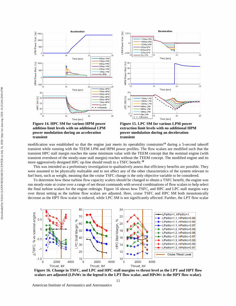
modification was established so that the engine just meets its operability constraints14 during a 5-second takeoff transient while running with the TEEM LPM and HPM power profiles. The flow scalars are modified such that the transient HPC stall margin reaches the same minimum value with the TEEM concept that the nominal engine (with transient overshoot of the steady-state stall margin) reaches without the TEEM concept. The modified engine and its more aggressively designed HPC op-line should result in a TSFC benefit.18
This was intended as a preliminary investigation to qualitatively assess that efficiency benefits are possible. They were assumed to be physically realizable and to not affect any of the other characteristics of the system relevant to fuel burn, such as weight, meaning that the cruise TSFC change is the only objective variable to be considered.
To determine how these turbine flow capacity scalers should be changed to obtain a TSFC benefit, the engine was run steady-state at cruise over a range of net thrust commands with several combinations of flow scalars to help select the final turbine scalars for the engine redesign. Figure 16 shows how TSFC, and HPC and LPC stall margins vary over thrust setting as the turbine flow scalars are adjusted. Here, cruise TSFC and HPC SM both monotonically decrease as the HPT flow scalar is reduced, while LPC SM is not significantly affected. Further, the LPT flow scalar
Figure 16. Change in TSFC, and LPC and HPC stall margins vs thrust level as the LPT and HPT flow scalars are adjusted (LPsWc in the legend is the LPT flow scalar, and HPsWc is the HPT flow scalar).
Figure 14. HPC SM for various HPM power addition limit levels with no additional LPM power modulation during an acceleration transient
Figure 15. LPC SM for various LPM power extraction limit levels with no additional HPM power modulation during an deceleration transient
Dow
nloa
ded
by N
ASA
GL
EN
N R
ESE
AR
CH
CE
NT
ER
on
July
16,
201
8 | h
ttp://
arc.
aiaa
.org
| D
OI:
10.
2514
/6.2
018-
4798

American Institute of Aeronautics and Astronautics
12
does not have a monotonic relationship with TSFC or HPC SM, however, reducing it consistently decreases LPC stall margin. Given that the minimum HPC SM was increased by about 2.2% by applying the TEEM concept as shown in Figure 11, the benefit the TEEM concept offers via engine redesign can be assessed by moving the op-line closer to the stall line such that the design HPC SM is reduced by about 2.2%. Based on the results shown here, the LPT and HPT flow scalars were chosen to be 1.10 and 0.95 respectively to obtain a TSFC reduction of about 0.75% for a HPC stall margin reduction of about 2.2%.
The next step after choosing how to revise the engine design is to verify that the revised design still meets the operability constraints. To do this, the revised engine was run through the same 4.5 second Wf transient, and the TEEM power modulation algorithm was run with the engine to generate TEEM power profiles for the transient. Worth noting is that the power addition/extraction required for the redesigned engine turned out to be almost identical to those for the nominal engine (not shown here). Specifically, the root-mean-squared (RMS) power difference required for the baseline vs the redesigned engine for the LPM computed over the 4.5 second transient is 45 horsepower, and the RMS difference between the respective HPM power levels is 25 horsepower. These are 2.6% and 2.9% of their 1750 and 850 horsepower motor ratings respectively, which suggests that the motor may not need to be redesigned. This would be the case assuming that the motors are originally designed for a baselined engine and later utilized for the redesigned engine. The HPC and LPC stall margin responses are shown in Figure 17.
This figure shows that the redesigned engine running with the TEEM concept is meeting the same minimum HPC SM during a 5-second transient as the baseline configuration (nominal engine design without the TEEM concept), as measured at a static condition. This shows that the TEEM concept can enable a more aggressive design in terms of HPC op-line to get a greater than 0.75% TSFC benefit while still running to the same transient stall margins and meeting the same performance (response time) requirements.
E. Engine Size Implications It is also valuable to know for which class of engines the TEEM concept applies. In order to begin answering this
question, a trade study was done to observe the effect of hFan engine spool inertias on the motor power inputs necessary to enable TEEM. Specifically, the low and high spool inertias on the hFan were varied between 50%, 100%, 150%, and 200% of their respective values, and the TEEM motor power level design function was run to determine how much power is necessary. To try and capture an even wider range of high spool inertias, the high spool inertia was also varied up to 500% of its nominal value. The peak motor power from the design function, along with the scaled inertia values from each run are plotted in Figure 18. Also included are curve fits to show the trends in the data, as well as vertical dashed lines corresponding to various spool inertia values known to the authors, providing context as to the range covered in the sensitivity study. The inertia values for the 28,000lbf N+3 geared turbofan19 and the 17,000 lbf hFan9 are computed from unpublished results of WATE++20 scripts for these engines. Both of these engines are sized for N+3 single aisle, narrow body aircraft. The Jet Cat shaft inertias are adapted from published work where a dynamic model of a small, hobby class turboshaft engine mated to a variable pitch propeller is developed.21 The C-MAPSS40k inertias are copied from the source code of the C-MAPSS40k engine dynamic model (a 40,000 lbf thrust class, dual spool turbofan representing the contemporary state of the art),22 and the 40,000 lbf T-MATS JT9D inertias are copied from the source of the JT9D example engine that comes with the Tool for Modeling and Analysis of Thermodynamic Systems (T-MATS) Simulink-based modeling package.23
As can be seen in the figure, the peak motor power required to implement the TEEM concept varies approximately linearly with spool inertia. Further, the motor power requirement for one spool primarily depends on the inertia of that respective spool, and not on the inertia of the other spool. Another takeaway from this chart is that the study covers
Figure 17. HPC and LPC stall margins with the baseline concept, the nominal engine running the TEEM concept, and a more efficient design of the engine running with TEEM.
Dow
nloa
ded
by N
ASA
GL
EN
N R
ESE
AR
CH
CE
NT
ER
on
July
16,
201
8 | h
ttp://
arc.
aiaa
.org
| D
OI:
10.
2514
/6.2
018-
4798

American Institute of Aeronautics and Astronautics
13
the range of low spool inertias for both modern and future technology level engines. However, the study only covers the high spool inertia range that is expected to be seen in future, ultra-high bypass or small core engines and not engines with a conventionally sized core (noting that C-MAPSS40k and the T-MATS JT9D engines have much larger high spool inertias than were tested in this study). Given this data, one can conclude that the TEEM concept should be applicable with 1-2MW electric machines for most futuristic, small core engines that target single aisle aircraft.
Also worth noting is that only the spool inertias were changed; these changes were not accompanied with any changes to the cycle or weight/flow path modeling, and so these results are only intended to examine the trend in TEEM motor design power versus shaft inertia, and not to determine what are specific, suitable design values for a given application. For instance, an engine may be redesigned to have a higher design value for HPC pressure ratio. This change may be implemented by adding another stage to the HPC which will change the inertia on the high spool, but will also likely result in more shaft power being delivered and extracted on the HPC, which would make a given HP motor design power appear smaller in comparison. This means that extrapolating these trends out to a significant degree will most likely yield inaccurate results.
V. Discussion The magnitude of the impact that TEEM could make will be dependent on the amount of transient stall margin
stack that can be reduced, the sensitivity of the engine design, other unknown constraints on the engine design, and the present limitations of electronics used to implement shaft speed control on air vehicles. Based on the findings from the hFan example, potential significant improvements in stability and or performance could be made. In this example, implementation of the TEEM concept led to a 2.2% and 5.7% improvement in HPC & LPC stall margin, respectively, and decreased the shaft speed overshoots as anticipated. Although the results are not shown, the peak T4 temperature was shaved by 24˚R. Using the expanded design space, a preliminary engine redesign was attempted by modifying the turbomachinery map scalers. This design modification resulted in a greater than 0.75% reduction in TSFC.
An interesting conclusion that fell out of the power trade studies was that a motor/generator capable of adding/extracting the full amount of power required for the engine to remain operating on the steady-state operating line is not necessary. In fact, a significantly lower amount of power could be added or extracted by the motor/generator and still provide the same or similar benefit. The basic study shows that power needs to be added to or extracted from both shafts simultaneously during an acceleration or deceleration transient, respectively, in order to remain on the steady-state operating line. However, the benefit to the compressor stall can be obtained by using only power extraction on the LPC during deceleration and power addition on the HPC during acceleration. This should reduce the overall energy consumption during transients, especially for accelerations. The power extraction during decelerations can be used to charge onboard energy storage devices. It was also shown how a variety of power schedules could be used to replace the VBV, which provides flexibility with the low power stability control implementation that could be utilized to manage energy, such as charging energy storage devices, expelling excess energy, or enforcing zero-sum energy accumulation.
The study also looked at engine size implications and presented results meant to help extrapolate the sizing of the electrical devices needed to implement the TEEM concept. For the hFan engine, the motor sizes needed fell within the feasibility range of electrical machines that have been already considered for hybrid electric propulsion. The amount of power/energy needed to employ the TEEM concept is greatly impacted by the moment of inertia of the
Figure 18. Shaft inertia sensitivity study results.
Dow
nloa
ded
by N
ASA
GL
EN
N R
ESE
AR
CH
CE
NT
ER
on
July
16,
201
8 | h
ttp://
arc.
aiaa
.org
| D
OI:
10.
2514
/6.2
018-
4798

American Institute of Aeronautics and Astronautics
14
engine shafts and appears to vary linearly with inertia. The results presented in this paper in regard to engine size implications are not meant to provide exact requirements for the electrical devices but simply to understand the driving factors and relationships with sizing, and provide a rough guess at the requirements for different sized engines. In this regard, the study has not considered the overall weight budget required to implement the TEEM concept and its implications on fuel and TSFC.
As we consider how TEEM could impact engines of different size, it’s also appropriate to consider how TEEM could impact propulsion system architectures spanning the thrust/power range. It is the belief of the authors that the TEEM concept could be applicable and beneficial to any turbomachinery that holds any amount of transient stall margin stack in order to ensure operability while transitioning between operating states. This applies to gas turbines with one or many shafts meant to produce thrust and or power. Therefore, regardless of the EAP configuration or application to an otherwise conventional turbofan engine, TEEM could produce a benefit. For application to an otherwise conventional turbofan, the benefit of TEEM will need to be weighed against the addition of electrical machines, while for various EAP concepts where most or all of the electrical components are already present, the TEEM concept is expected to be even more advantageous.
VI. Conclusions The Turbine Electrified Energy Management (TEEM) concept was presented and demonstrated with considerable
background information and discussion of its potential benefits. This operability control concept shows promise in its capability to expand the engine design space and enable performance and efficiency benefits. It also possesses the potential to consolidate and simplify control implementation with such benefits as eliminating the need for a Variable Bleed Valve. The TEEM concept and several of its benefits have been demonstrated through an open-loop example using a model of the hFan propulsion system. The hFan is a parallel hybrid electric turbofan with a 1380 hp electric motor connected to the low pressure spool designed to augment thrust. Concept feasibility has been supported through simulation demonstrating that significant benefits can be achieved with modestly sized motors on each of the engine shafts with a modestly sized energy storage element. Observations from the study revealed that independent control of the shaft speeds could achieve the stated goals of TEEM; power modulation on the Low Pressure Shaft was not necessary during accelerations while power modulation on the High Pressure Shaft was not necessary during decelerations. A suboptimal engine redesign was attempted to demonstrate a benefit in efficiency, showing a positive impact on steady-state performance through use of a transient control technology. Some engine size implications were drawn from a prior hFan study and further discussion was provided in consideration of the applicability of the TEEM concept to a wide range of aero-propulsion systems. Work is ongoing to investigate control strategies and to design active control algorithms that can be used to implement the TEEM concept over the entire flight envelope of an engine.
Appendices
A. Compressor Transient Off-Design Performance Considering that compressor stall and surge must be avoided at all costs, it helps to visualize what is happening
within the engine. Understand that changing conditions cause the internal flow to respond very rapidly with respect to the change in speed of the high inertia rotational components. The high pressure spool (HPS) responds faster to flow change than the low pressure spool (LPS) due to the former’s smaller moment of inertia. Furthermore, the only way to modify the speed of the HPS and LPS is to transfer power through the effectiveness of the fluid dynamic coupling (incidence angle) to the blading, which is a function of axial gas path flow and blade velocities. Therefore, the mismatch in shaft dynamics, along with transitioning flow rates throughout the engine during transient operation, can result in the compressor blades operating off-incidence, leading to flow instabilities, high loading conditions and eventually to stall or surge.
During an acceleration, (increasing fuel flow, combustor output), both spools speeds immediately begin to lag behind the change in axial gas path flow velocity. Referring to Figure A1, and considering the flow increases to be infinitesimally small steps, the high-pressure compressor (HPC) operating point moves to the right on the compressor map and a higher pressure rise to match the additional work being extracted by the turbine. The additional flow increases the pressure rise for the HPC, but does not match the op-line design point because the new speed state is insufficient and still being established. The steady-state flow condition will establish when both compressors are drawing air at the proper flow rate and incidence angle. The higher-than-normal pressure rise for the given flow condition increases the loading on the HPC blades and reduces (worsens) stall margin. See green dot moving from 1 to 2 on the map in Figure A1. Meanwhile, the low pressure compressor (LPC) responds much slower than the HPC due to its larger moment of inertia. For the same infinitesimal step in flow, it tends to move down the same speed line.
Dow
nloa
ded
by N
ASA
GL
EN
N R
ESE
AR
CH
CE
NT
ER
on
July
16,
201
8 | h
ttp://
arc.
aiaa
.org
| D
OI:
10.
2514
/6.2
018-
4798

American Institute of Aeronautics and Astronautics
15
This decreases the pressure rise, relative to the flow condition, and unloads the LPC blades, which increases (improves) the stall margin.
During a deceleration, (decreasing fuel flow, combustor output), the HPS responds faster than the LPS, as expected. The HPC moves to a slower speed line because the change in flow through the turbine provides the HPC with less torque. For that instantaneous flow and speed condition, the HPC has lower pressure rise (less loading) and more stall margin than the design point. Meanwhile, the LPC is still spinning at nearly the same speed due to inertia but with less mass flow than required by design. This increases the loading on the LPC blades, forcing it up the speed line to a higher pressure rise. See red dot moving from 1 to 2 on the map in Figure A1.
B. Flow Chart describing the determination of the Power Modulation Profile
Acknowledgments The authors would like to acknowledge the Convergent Aeronautic Solutions (CAS) program at NASA Glenn
Research Center for supporting a short investigative effort to test the TEEM concept. This includes the support from Gerard Welch and Greg Follen. Also worthy of recognition is the Transformational Tools & Technologies (TTT) project under the Aerospace Research Mission Directorate (ARMD) that has supported this work since. The authors would also like to acknowledge those within NASA who contributed to creation of the hFan model that was utilized in this study including Kenneth Fisher and Scott Jones. Finally the authors want to acknowledge the support of Sanjay Garg, Chief of the Intelligent Control and Autonomy Branch at NASA Glenn Research Center.
Figure B1. Algorithm for determining Power Modulation Profile.
Figure A1. The expected and observed compressor transient response for an infinitesimally small acceleration and deceleration without electrical speed control modulation.
Dow
nloa
ded
by N
ASA
GL
EN
N R
ESE
AR
CH
CE
NT
ER
on
July
16,
201
8 | h
ttp://
arc.
aiaa
.org
| D
OI:
10.
2514
/6.2
018-
4798

American Institute of Aeronautics and Astronautics
16
References
1 Holmes, B. J., Parker, R. A., Stanley, D., McHugh, P., Garrow, L., Masson, P. M., Olcott, J., “NASA Strategic Framework for On-Demand Air Mobility,” NASA Contract NNL13AA08B, 2017.
2 Commercial aircraft propulsion and energy systems research: reducing global carbon emissions. National Academies Press, 2016. 3 Jansen, J. H., Bowman, C., Jankovsky, A., Dyson, R., Felder, J., “Overview of NASA Electrified Aircraft Propulsion Research
for Large Subsonic Transports,” AIAA Propulsion and Energy Forum, Atlanta, GA. 2017. 4 Follen, G., Del Rosario, R., Wahls, R., and Madavan, N., "NASA's Fundamental Aeronautics Subsonic Fixed Wing Project:
Generation N+3 Technology Portfolio," SAE Technical Paper 2011-01-2521, 2011. 5 Welstead, J. R., Felder, J. L., “Conceptual Design of a Single-Aisle Turboelectric Commercial Transport with Fuselage Boundary
Layer Ingestion,” AIAA SciTech Forum, San Diego, CA. 2016. 6 Felder, J. L., Tong, M. T., Chu, J., “Senstivity of Mission Energy Consumption to Turboelectric Distributed Propulsion Design
Assumptions on the N3-X Hybrid Wing Body Aircraft,” 48th AIAA/ASME/SAE/ASEE Joint Propulsion Conference & Exhibit, Atlanta, GA. 2012
7 Faidi, A., "Effect of Accessory Power Take-off Variation on a Turbofan Engine Performance," M.S. Dissertation, Department of Aeronautics and Astronautics, Air Force Institute of Technology, Dayton, OH. 2012.
8 Derouineau, J.-L., Honeywell International, Inc., Morristown, NJ, U.S. Patent Application for “Engine Power Extraction Control System,” Application No. 11/182,550, filed 25 Aug. 2004.
9 Bradley, M. K., Droney, C. K., “Subsonic Utlra Green Aircraft Research: Phase II – Volume II – Hybrid Electric Design Exploration,” NASA CR-218704. 2015.
10 Chin, J. C., Csank, J. T., Haller, W. J., Seidel, J. A., “An Introduction to Transient Engine Applications Using the Numerical Propulsion System Simulation (NPSS) and MATLAB,” NASA/TM-218922. 2016.
11 Federal Aviation Administration, “Title 14 of the Code of Federal Regulations”, http://www.ecfr.gov/cgi-bin/text-idx?SID=aa3a99819fbf162f142eee0ec759f8df&mc=true&node=se14.1.33_173&rgn=div8, accessed October, 2017.
12 Volponi, A.J., “Gas Turbine Parameter Corrections,” Journal of Engineering for Gas Turbines and Power, Vol. 121, 1999, pp. 613–621
13 Zinnecker, A. M., Csank, J. T., “A methodology to assess the capability of engine designs to meet closed-loop performance and operability requirements,” 51st AIAA/SAE/ASEE Joint Propulsion Conference, Orlando, FL. 2015.
14 Csank, J. T., Zinnecker, A. M., “Application of the Tool for Turbine Engine Closed-loop Transient Analysis (TTECTrA) for Dynamic Systems Analysis,” NASA/TM-218449. 2014.
15 Csank, J. T., “Dynamic Systems Analysis for Turbine Based Aero Propulsion Systems,” NASA/TM-219133. 2016. 16 Csank, J. T., Thomas, G. L., “Dynamic Analysis for a Geared Turbofan Engine with Variable Area Fan Nozzle,” AIAA
Propulsion and Energy Forum, Atlanta, GA. 2017. 17 Norris, G., Warwick, G., “A Reversed, Tilted Future for Pratt’s Geared Turbofan,” Aviation Week and Space Technology [online
article], URL: http://aviationweek.com/technology/reversed-tilted-future-pratt-s-geared-turbofan [cited 28 October 2017]. 18 Connolly, J. W., Csank, J. T., Chicatelli, A., “Advanced Control Considerations for Turbofan Engine Design,” 52nd
AIAA/SAE/ASEE Joint Propulsion Conference, Salt Lake City, UT. 2016. 19 Jones, S. M., Haller, W. J., Tong, M. T., “An N+3 Technology Level Reference Propulsion System,” NASA/TM-219501. 2017. 20 Tong, M. T., Naylor, B. A., “An Object-oriented Computer Code for Aircraft Engine Weight Estimation,” Proceedings of ASME
Turbo Expo 2008, Berlin, Germany. 2008 21 Pakmehr, M., Fitzgerald, N., Feron, E., Paduano, J., Behbahani, A., “Physics-Based Dynamic Modeling of a Turboshaft Engine
Driving a Variable Pitch Propeller,” AIAA Journal of Propulsion and Power. Vol. 32, No. 3, May-June 2016. 22 May, R.D., Csank, J., Lavelle, T.M., Litt, J.S., and Guo, T.-H., “A High Fidelity Simulation of a Generic Commercial Aircraft
Engine and Controller,” 46th AIAA/ASME/SAE/ASEE Joint Propulsion Conference, Nashville, TN, July 25-28, 2010. 23 Chapman, J. W., Lavelle, T. M., May, R. D., Litt, J. S., and Guo, T.-H., Toolbox for the Modeling and Analysis of
Thermodynamic Systems (T-MATS) User’s Guide, NASA/TM-2014-216638, January 2014.
Dow
nloa
ded
by N
ASA
GL
EN
N R
ESE
AR
CH
CE
NT
ER
on
July
16,
201
8 | h
ttp://
arc.
aiaa
.org
| D
OI:
10.
2514
/6.2
018-
4798