tt31 transponder installation manual · tt31 transponder installation manual 27 march 2012 00455-00...
TRANSCRIPT

TT31 Mode S Transponder
Installation Manual
00455-00-AM
27 March 2012
Trig Avionics Limited Heriot Watt Research Park Riccarton, Currie EH14 4AP Scotland, UK Copyright Trig Avionics Limited, 2012

This page intentionally left blank

TT31 Transponder Installation Manual 27 March 2012 00455-00 Issue AM
______________________
CONTENTS
1. PREFACE ....................................................................................................................................... 1
1.1 PURPOSE.................................................................................................................................... 1
1.2 SCOPE........................................................................................................................................ 1
1.3 CHANGES FROM PREVIOUS ISSUE .............................................................................................. 1
1.4 DOCUMENT CROSS-REFERENCES .............................................................................................. 1
2. INTRODUCTION .......................................................................................................................... 2
2.1 TT31 DESCRIPTION ................................................................................................................... 2
2.2 INTERFACES............................................................................................................................... 2
3. TECHNICAL SPECIFICATIONS............................................................................................... 4
3.1 REGULATORY ............................................................................................................................ 4
3.1.1 Approved Deviations ........................................................................................................ 4
3.2 PHYSICAL SPECIFICATIONS (IN TRAY) ....................................................................................... 4
3.3 INSTALLATION APPROVAL......................................................................................................... 5
3.4 NON – TSO FUNCTIONS ............................................................................................................ 5
4. UNIT AND ACCESSORIES SUPPLIED..................................................................................... 6
4.1 TT31 MODE S TRANSPONDER ITEMS ........................................................................................ 6
4.2 INSTALLATION KIT .................................................................................................................... 6
4.3 DOCUMENTATION KIT ............................................................................................................... 6
4.4 REQUIRED ITEMS....................................................................................................................... 6
5. INSTALLATION ........................................................................................................................... 8
5.1 UNPACKING AND INSPECTING EQUIPMENT ................................................................................ 8
5.2 MOUNTING ................................................................................................................................ 8
5.3 COOLING REQUIREMENTS ......................................................................................................... 8
5.4 ELECTRICAL CONNECTIONS ...................................................................................................... 8
5.4.1 Primary Interface – Pinout............................................................................................... 9
5.4.2 Secondary Interface - Pinout.......................................................................................... 10
5.4.3 Orientation Diagram ...................................................................................................... 10
5.5 INTERFACE DETAILS................................................................................................................ 11
5.5.1 Power Input .................................................................................................................... 11
5.5.2 Lighting Bus Input .......................................................................................................... 11
5.5.3 Mutual Suppression ........................................................................................................ 11
5.5.4 Altitude Inputs and Output ............................................................................................. 11
5.5.5 Squat Switch Input .......................................................................................................... 12
5.5.6 Ident Switch Input........................................................................................................... 12
5.5.7 External Standby Input ................................................................................................... 12
Trig Avionics Limited i

TT31 Transponder Installation Manual 27 March 2012 00455-00 Issue AM
______________________
5.5.8 Audio Output .................................................................................................................. 12
5.5.9 Altitude Alerter Output ................................................................................................... 12
5.5.10 GPS Position Input ......................................................................................................... 13
5.5.11 TIS Traffic Output........................................................................................................... 13
5.6 MOLEX CRIMP TERMINALS ..................................................................................................... 13
5.7 ANTENNA INSTALLATION ........................................................................................................ 14
5.7.1 Antenna Cable ................................................................................................................ 14
5.7.2 BNC Connector............................................................................................................... 16
5.8 TRAY / BNC CONNECTOR ASSEMBLY ..................................................................................... 17
6. INSTALLATION SETUP AND TEST....................................................................................... 19
6.1 CONFIGURATION ITEMS........................................................................................................... 19
6.1.1 Aircraft Address Programming ...................................................................................... 19
6.1.2 VFR Squawk Code.......................................................................................................... 19
6.1.3 VFR Flight ID................................................................................................................. 19
6.1.4 Airspeed Category .......................................................................................................... 20
6.1.5 Aircraft Category............................................................................................................ 20
6.1.6 Squat Switch Source ....................................................................................................... 20
6.1.7 TIS Output ...................................................................................................................... 20
6.1.8 GPS Input ....................................................................................................................... 20
6.1.9 GPS/TIS Line Speed ....................................................................................................... 20
6.1.10 GPS System Certification Level...................................................................................... 20
6.1.11 GPS NACv ...................................................................................................................... 21
6.1.12 Aircraft Length and Width.............................................................................................. 21
6.1.13 GPS Antenna Offset ........................................................................................................ 21
6.1.14 ADS-B Receiver Options ................................................................................................ 21
6.1.15 Audio Volume ................................................................................................................. 21
6.1.16 LCD Dim Point............................................................................................................... 21
6.1.17 LCD Brightness .............................................................................................................. 22
6.2 TEST ITEMS.............................................................................................................................. 22
6.2.1 Interface Check............................................................................................................... 22
6.2.2 Altitude Check................................................................................................................. 22
6.2.3 Lighting Bus.................................................................................................................... 22
6.2.4 GPS Interface ................................................................................................................. 22
7. POST INSTALLATION CHECKS ............................................................................................ 23
8. NORMAL OPERATION............................................................................................................. 24
8.1 OVERVIEW............................................................................................................................... 24
8.2 DISPLAY .................................................................................................................................. 24
ii Trig Avionics Limited

TT31 Transponder Installation Manual 27 March 2012 00455-00 Issue AM
______________________
8.3 MODE SELECTOR KNOB .......................................................................................................... 24
8.4 PUSH BUTTONS........................................................................................................................ 25
8.5 CODE SELECTOR KNOB ........................................................................................................... 25
8.6 FLIGHT TIMER ......................................................................................................................... 25
8.7 STOPWATCH ............................................................................................................................ 25
8.8 ADS-B POSITION MONITOR .................................................................................................... 25
8.9 ALTITUDE MONITOR ............................................................................................................... 26
8.10 WARNINGS .............................................................................................................................. 26
8.11 FAULT ANNUNCIATION............................................................................................................ 26
8.12 LOW TEMPERATURE OPERATION............................................................................................. 26
9. CONTINUED AIRWORTHINESS ............................................................................................ 27
10. LIMITED WARRANTY ......................................................................................................... 28
11. ENVIRONMENTAL QUALIFICATION FORM................................................................. 29
12. ADS-B COMPLIANCE ........................................................................................................... 31
12.1 ADS-B PARAMETERS SUPPORTED .......................................................................................... 31
12.2 FAA 91.227 COMPLIANCE ...................................................................................................... 31
12.3 AMC 20-24 COMPLIANCE....................................................................................................... 32
12.4 AUTOMATIC AIR/GROUND DETERMINATION........................................................................... 32
12.5 ADS-B SUPPORT..................................................................................................................... 32
13. INSTALLATION DRAWINGS .............................................................................................. 33
14. BASIC INTERCONNECT DIAGRAM ................................................................................. 34
Trig Avionics Limited iii

TT31 Transponder Installation Manual 27 March 2012 00455-00 Issue AM
______________________
iv Trig Avionics Limited
This page intentionally left blank
TT31 Transponder Installation Manual 27 March 2012 00455-00 Issue AM
______________________
1. Preface
1.1 Purpose
This manual describes the physical and electrical characteristics and the installation requirements for a TT31 Mode S Transponder.
1.2 Scope
This document applies to the installation of the TT31 Mode S Transponder.
At the publication date of this manual the software version identifier for the TT31 is 3.1 and the FPGA version identifier is 231006a. The software and FPGA versions are subject to change without notice.
1.3 Changes from Previous Issue
Changes from Issue AL to Issue AM are:
Section 5.5.4 Addition of Shadin air data computer (ADC) compatibility
Section 5.5.11 Addition of GARMIN ADS-B protocol compatibility
Section 12 Additional GPS units listed for ADS-B compliance
Section 14 Wiring Diagram updated to make pin identification clearer.
1.4 Document Cross-References
00454-00 TT31 Mode S Transponder Operating Manual AE
Trig Avionics Limited Page 1

TT31 Transponder Installation Manual 27 March 2012 00455-00 Issue AM
______________________
2. Introduction
2.1 TT31 Description
The TT31 Mode S panel mount transponder is an ED-73B Class 1 compliant Mode S level 2es datalink transponder, with support for extended squitter, elementary surveillance and SI codes. The TT31 is also a DO-260B Class B1S compliant ADS-B out participant. The TT31 meets the relevant environmental requirements of ED-14D, and is certified to ETSO 2C112b, ETSO C166a, TSO C112 and TSO C166b.
The TT31 transmitter power output is nominally 240 watts, and the transponder runs from either 14 volt nominal or 28 volt nominal DC power supply with no configuration changes required.
The TT31 transponder responds to both legacy Mode A/C interrogations and to Mode S interrogations from both ground radar and airborne collision avoidance systems. In all cases, the interrogations are received by the transponder on 1030MHz, and replies are transmitted on 1090MHz.
In the Mode S environment, S stands for Select, and a Mode S interrogator can selectively address a single transponder. This allows accurate position plotting with lower reply rates, which in turn reduces frequency congestion and interference. As a side benefit, power consumption by the transponder may be reduced, and simple datalink services can be supported, such as ADS-B. It is however crucial to the reliable operation of the system that each aircraft has a distinct Mode S address. The Mode S address is allocated by the registration authority for the aircraft, and must be set when the TT31 is installed.
2.2 Interfaces
At the rear, the transponder has two Molex style connectors and a single antenna connector for blind mating with the corresponding connectors in the mounting tray.
The interfaces provide the following services:
Parallel altitude input Connection to an external altitude encoder using parallel Gray code.
Serial altitude input Connection to an external RS232 altitude encoder. Using serial altitude data allows the transponder to report altitude with 25 foot resolution.
Serial altitude output Connection to a GPS or other device needing serial altitude data – this allows the transponder to act as a repeater instead of requiring a second altitude encoder.
Ident input External IDENT switch input.
Standby input External standby input for dual transponder installations.
“On ground” input Allows automatic flight/ground mode switching for aircraft with a squat switch.
Lighting bus input Used to adjust the backlight and switch lighting intensity.
DME Suppression Input
Input to limit interference between DME interrogations and transponder replies – suppresses transponder whilst active.
Suppression bus I/O ARINC compatible suppression bus signal used in aircraft with more sophisticated suppression needs, both an input to and output from the transponder.
Audio output Optionally used by the altitude monitor function.
Audio mute input Toggle function to mute the audio output.
Altitude alert output Output used to signal altitude deviations when optional altitude monitor function is used.
GPS Input Connection to a GPS supplying position input for ADS-B position reporting.
Page 2 Trig Avionics Limited

TT31 Transponder Installation Manual 27 March 2012 00455-00 Issue AM
______________________
TIS Output RS232 output for connection to traffic display.
Trig Avionics Limited Page 3
TT31 Transponder Installation Manual 27 March 2012 00455-00 Issue AM
______________________
3. Technical Specifications
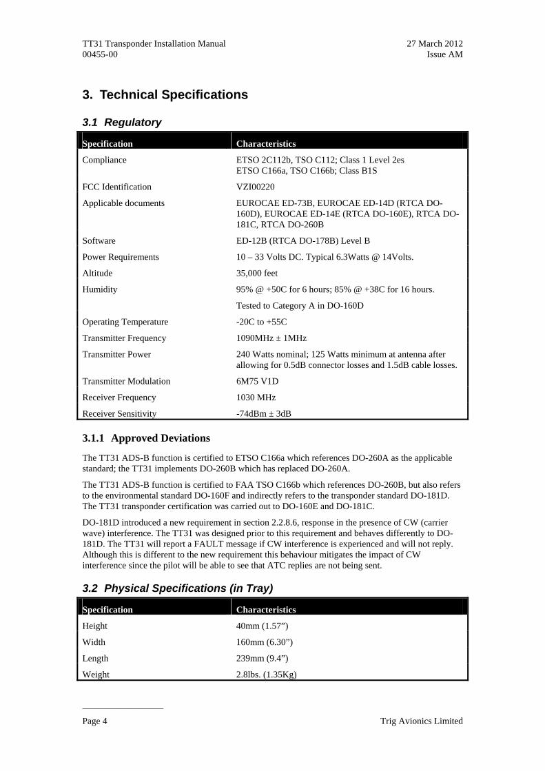
3.1 Regulatory
Specification Characteristics
Compliance ETSO 2C112b, TSO C112; Class 1 Level 2es ETSO C166a, TSO C166b; Class B1S
FCC Identification VZI00220
Applicable documents EUROCAE ED-73B, EUROCAE ED-14D (RTCA DO-160D), EUROCAE ED-14E (RTCA DO-160E), RTCA DO-181C, RTCA DO-260B
Software ED-12B (RTCA DO-178B) Level B
Power Requirements 10 – 33 Volts DC. Typical 6.3Watts @ 14Volts.
Altitude 35,000 feet
Humidity 95% @ +50C for 6 hours; 85% @ +38C for 16 hours.
Tested to Category A in DO-160D
Operating Temperature -20C to +55C
Transmitter Frequency 1090MHz ± 1MHz
Transmitter Power 240 Watts nominal; 125 Watts minimum at antenna after allowing for 0.5dB connector losses and 1.5dB cable losses.
Transmitter Modulation 6M75 V1D
Receiver Frequency 1030 MHz
Receiver Sensitivity -74dBm ± 3dB
3.1.1 Approved Deviations
The TT31 ADS-B function is certified to ETSO C166a which references DO-260A as the applicable standard; the TT31 implements DO-260B which has replaced DO-260A.
The TT31 ADS-B function is certified to FAA TSO C166b which references DO-260B, but also refers to the environmental standard DO-160F and indirectly refers to the transponder standard DO-181D. The TT31 transponder certification was carried out to DO-160E and DO-181C.
DO-181D introduced a new requirement in section 2.2.8.6, response in the presence of CW (carrier wave) interference. The TT31 was designed prior to this requirement and behaves differently to DO-181D. The TT31 will report a FAULT message if CW interference is experienced and will not reply. Although this is different to the new requirement this behaviour mitigates the impact of CW interference since the pilot will be able to see that ATC replies are not being sent.
3.2 Physical Specifications (in Tray)
Specification Characteristics
Height 40mm (1.57”)
Width 160mm (6.30”)
Length 239mm (9.4”)
Weight 2.8lbs. (1.35Kg)
Page 4 Trig Avionics Limited
TT31 Transponder Installation Manual 27 March 2012 00455-00 Issue AM
______________________
3.3 Installation Approval
The conditions and tests required for the TSO approval of the TT31 Mode S Transponder are minimum performance standards. It is the responsibility of those desiring to install this transponder on or within a specific type or class of aircraft to determine that the aircraft operating conditions are within the TSO standards. The transponder may be installed only if further evaluation by the user/installer documents an acceptable installation that is approved by the appropriate airworthiness authority.
3.4 Non – TSO Functions
The TT31 Mode S Transponder contains the following non-TSO functions:
Stopwatch and Flight Timer. The transponder provides a simple stopwatch and flight timer function, displayed on the front panel.
Altitude Monitor. The Altitude Monitor activates an audio annunciator or annunciator light (depending on installation) when the aircraft pressure altitude differs from the previously selected altitude by more than 200 feet.
Altitude Repeater. This is a serial altitude output that can connect to a GPS or other device needing serial altitude data – this allows the transponder to act as a repeater for the altitude input instead of requiring a second altitude encoder.
The operation of each of these functions is described later in this manual.
The non-TSO functions defined in this section are not part of the TSO approval. The non-TSO function data included in this section is approved under 14 CFR 21.305(d).
Trig Avionics Limited Page 5
TT31 Transponder Installation Manual 27 March 2012 00455-00 Issue AM
______________________
4. Unit and Accessories supplied
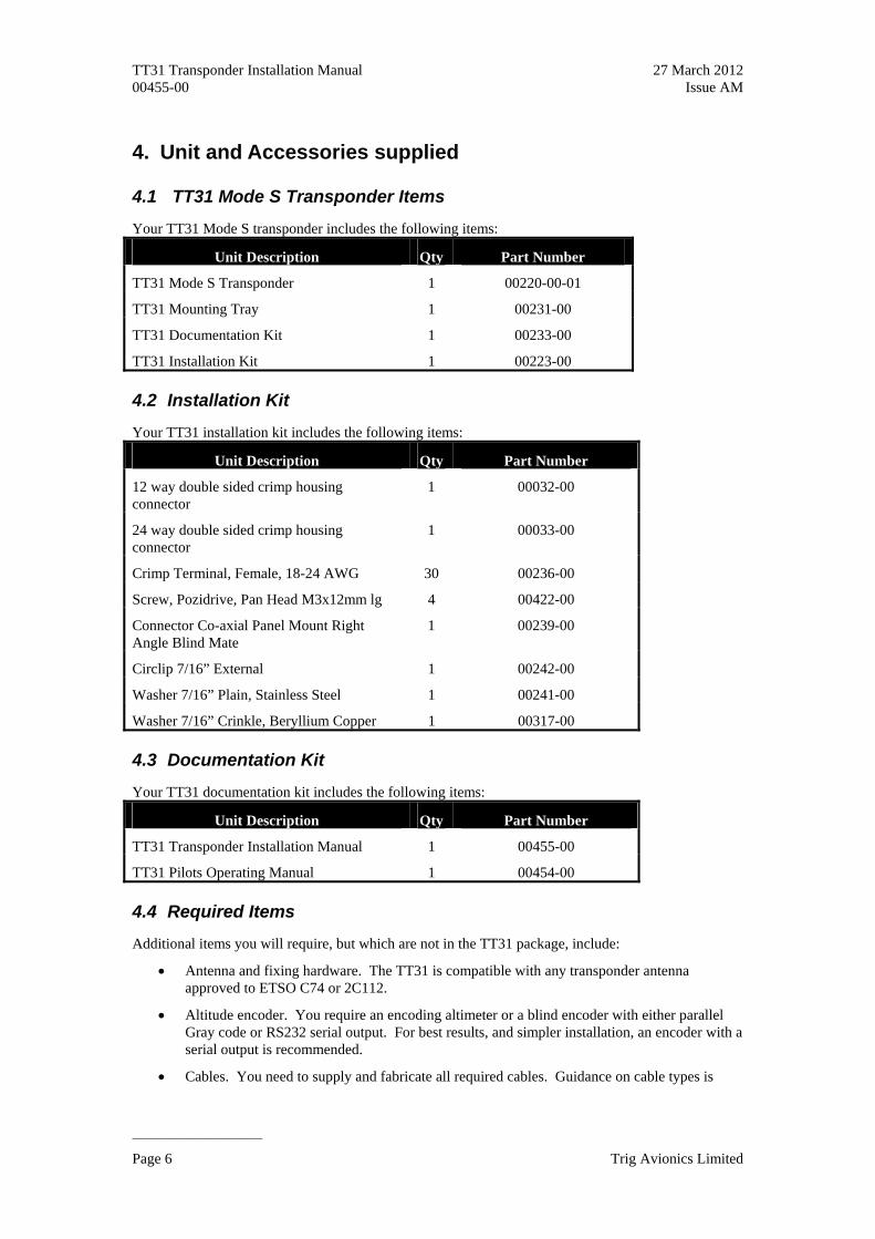
4.1 TT31 Mode S Transponder Items
Your TT31 Mode S transponder includes the following items:
Unit Description Qty Part Number
TT31 Mode S Transponder 1 00220-00-01
TT31 Mounting Tray 1 00231-00
TT31 Documentation Kit 1 00233-00
TT31 Installation Kit 1 00223-00
4.2 Installation Kit
Your TT31 installation kit includes the following items:
Unit Description Qty Part Number
12 way double sided crimp housing connector
1 00032-00
24 way double sided crimp housing connector
1 00033-00
Crimp Terminal, Female, 18-24 AWG 30 00236-00
Screw, Pozidrive, Pan Head M3x12mm lg 4 00422-00
Connector Co-axial Panel Mount Right Angle Blind Mate
1 00239-00
Circlip 7/16” External 1 00242-00
Washer 7/16” Plain, Stainless Steel 1 00241-00
Washer 7/16” Crinkle, Beryllium Copper 1 00317-00
4.3 Documentation Kit
Your TT31 documentation kit includes the following items:
Unit Description Qty Part Number
TT31 Transponder Installation Manual 1 00455-00
TT31 Pilots Operating Manual 1 00454-00
4.4 Required Items
Additional items you will require, but which are not in the TT31 package, include:
Antenna and fixing hardware. The TT31 is compatible with any transponder antenna approved to ETSO C74 or 2C112.
Altitude encoder. You require an encoding altimeter or a blind encoder with either parallel Gray code or RS232 serial output. For best results, and simpler installation, an encoder with a serial output is recommended.
Cables. You need to supply and fabricate all required cables. Guidance on cable types is
Page 6 Trig Avionics Limited

TT31 Transponder Installation Manual 27 March 2012 00455-00 Issue AM
______________________
given in section 5 below.
Fixings. To secure the transponder tray to the airframe you will need at least 6 flat head screws and six self-locking nuts. If the aircraft does not have existing mounting provisions you may need to fabricate additional brackets to support the transponder tray.
To support the optional ADS-B features a GPS receiver with an appropriate serial output is required. To support the optional TIS features a display with an appropriate serial input is required.
Trig Avionics Limited Page 7
TT31 Transponder Installation Manual 27 March 2012 00455-00 Issue AM
______________________
5. Installation
5.1 Unpacking and Inspecting Equipment
Carefully unpack the transponder and make a visual inspection of the unit for evidence of any damage incurred during shipment. If the unit is damaged, notify the shipping company to file a claim for the damage. To justify your claim, save the original shipping container and all packaging materials.
5.2 Mounting
The TT31 Mode S transponder must be mounted rigidly in the aircraft panel. The following installation procedure should be followed, remembering to allow adequate space for installation of cables and connectors.
Select a position in the panel that is not too close to any high external heat source. (The TT31 is not a significant heat source itself and does not need to be kept away from other devices for this reason).
Avoid sharp bends and placing the cables too near to the aircraft control cables.
Secure the mounting tray (p/n 00231-00) to the instrument panel via the six (6) mounting holes in the tray. It is important that the tray is supported at the rear two mounting holes as well as the front four.
Check that the locking mechanism is correctly oriented by unscrewing the locking screw if required.
Slide the TT31 transponder into the secured mounting tray.
Lock the TT31 transponder into the mounting tray using a 3/32” Allen key, taking care not to over tighten the locking screw.
5.3 Cooling Requirements
The TT31 Mode S transponder meets all applicable ETSO requirements without forced air-cooling.
Attention should however be given to the incorporation of cooling provisions to limit the maximum operating temperature of each unit when the TT31 is installed in a typical panel or rack. The reliability of equipment operating in close proximity in a rack can be degraded if adequate cooling is not provided.
5.4 Electrical Connections
The TT31 has two Molex edge connectors, one with 24 contacts, which is the primary interface, and a second connector with 12 contacts which carries signals to support ADS-B and uplinked TIS traffic. A single coaxial connector attaches to the antenna. The only feature of the current TT31 that depends on the second Molex connector is the altitude alerter. In simple installations it is therefore possible to omit wiring for the second connector altogether.
The Molex edge connector used in the TT31 is similar to the connector used on the KT76A and KT78A transponders, and the common signals on the primary connector use the same contact positions and are electrically compatible. The antenna connector is also compatible. Providing that the wiring is appropriately installed, it is intended that you can upgrade a KT76A or KT78A installation to the TT31 without any connector rewiring. Before doing that however, you MUST check that the wiring for the existing transponder is in good condition.
Page 8 Trig Avionics Limited
TT31 Transponder Installation Manual 27 March 2012 00455-00 Issue AM
______________________
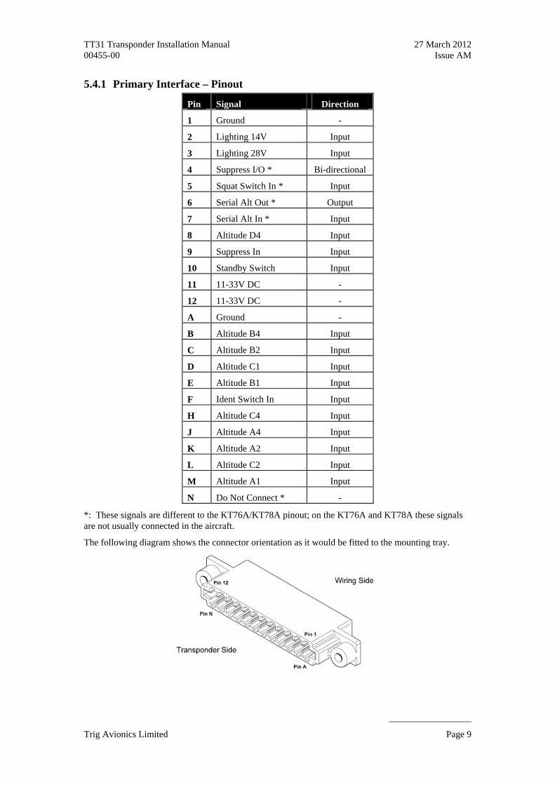
5.4.1 Primary Interface – Pinout
Pin Signal Direction
1 Ground -
2 Lighting 14V Input
3 Lighting 28V Input
4 Suppress I/O * Bi-directional
5 Squat Switch In * Input
6 Serial Alt Out * Output
7 Serial Alt In * Input
8 Altitude D4 Input
9 Suppress In Input
10 Standby Switch Input
11 11-33V DC -
12 11-33V DC -
A Ground -
B Altitude B4 Input
C Altitude B2 Input
D Altitude C1 Input
E Altitude B1 Input
F Ident Switch In Input
H Altitude C4 Input
J Altitude A4 Input
K Altitude A2 Input
L Altitude C2 Input
M Altitude A1 Input
N Do Not Connect * -
*: These signals are different to the KT76A/KT78A pinout; on the KT76A and KT78A these signals are not usually connected in the aircraft.
The following diagram shows the connector orientation as it would be fitted to the mounting tray.
Trig Avionics Limited Page 9
TT31 Transponder Installation Manual 27 March 2012 00455-00 Issue AM
______________________
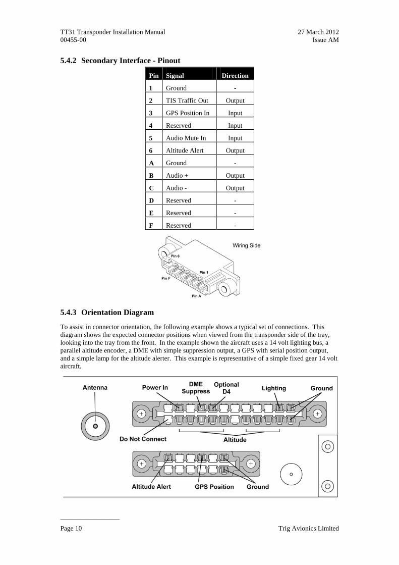
5.4.2 Secondary Interface - Pinout
Pin Signal Direction
1 Ground -
2 TIS Traffic Out Output
3 GPS Position In Input
4 Reserved Input
5 Audio Mute In Input
6 Altitude Alert Output
A Ground -
B Audio + Output
C Audio - Output
D Reserved -
E Reserved -
F Reserved -
5.4.3 Orientation Diagram
To assist in connector orientation, the following example shows a typical set of connections. This diagram shows the expected connector positions when viewed from the transponder side of the tray, looking into the tray from the front. In the example shown the aircraft uses a 14 volt lighting bus, a parallel altitude encoder, a DME with simple suppression output, a GPS with serial position output, and a simple lamp for the altitude alerter. This example is representative of a simple fixed gear 14 volt aircraft.
Page 10 Trig Avionics Limited

TT31 Transponder Installation Manual 27 March 2012 00455-00 Issue AM
______________________
5.5 Interface Details
5.5.1 Power Input
The power supply can be 11-33 Volts DC; no voltage adjustment is required. Contacts 11 and 12 on the 24 way connector are both available as power inputs. This is for compatibility reasons only – internally the two are connected together, and in most installations only one need be connected to the power supply.
Use a 3 Amp circuit breaker for power supply protection to the TT31.
5.5.2 Lighting Bus Input
The TT31 will adjust the brightness of the front panel switch lighting according to the voltage on the lighting bus input. Two lighting bus inputs are provided on the 24 way connector to accommodate aircraft with 14 Volt or 28 Volt lighting systems. When the lighting bus operates at 28 Volts, connect the bus input to contact 3, and leave contact 2 unconnected. When the lighting bus operates at 14
act 2. In this case contact 3 can be left unconnected, but for grounded instead with no effect.
detected, the TT31 will automatically control the front panel lighting based
sion allows two or more transmitters on adjacent frequencies to inhibit the other mmonly used between n avoidance systems.
utual suppression interface on the 24 way connector. The Suppress n aircraft with simple DME systems and no other suppression
sed utput
never the bus has greater than
5.5.4 Altitude Inputs and Output
Gray code altitude input, or serial RS232 altitude input. Both of e
y
allel encoder inputs are active when the voltage to ground is pulled below approximately 4
for D4. In an aircraft with a service ceiling below 30,000 feet input D4 will never be active, and can safely be left unconnected.
Volts, connect the bus input to contbackwards compatibility may also be
If no lighting bus input ison the ambient light sensor.
5.5.3 Mutual Suppression
Mutual supprestransmitters when one is active to limit the interference effects. It is cotransponders and DME systems, and between transponders and collisio
The TT31 provides two styles of minput on contact 9 is typically used irequirements. It is an input only, and is active whenever the input is greater than approximately 5 Volts.
The Suppress I/O on contact 4 is an ARINC compatible suppression bus interface, which acts as both an input and an output. The TT31 will assert this signal when it is transmitting, and can be suppresby other equipment that asserts the signal. The TT31 will drive approximately 24 Volts on the o(independently of supply voltage), and will treat the input as active whe10 Volts.
The TT31 can use either a parallelthese interfaces are on the 24 way connector. If the altitude encoder you are using offers both, wrecommend using the RS232 serial input. Serial formats allow a higher resolution altitude representation that can be used by Mode S interrogations, whereas parallel Gray code format can onlrepresent altitude to the nearest 100 feet. You must choose between serial or parallel formats – you should NOT connect both. If a parallel encoder is connected the TT31 will always use that as the altitude source even if a serial encoder is also connected.
The parVolts. The TT31 includes internal isolation diodes which prevent the unit from pulling the encoder lines to ground when the transponder is switched off. The TT31 can therefore share the altitude inputs with other devices without needing external isolation.
Parallel output altitude encoders intended for operation below 30,000 feet may not have a signal connection
Trig Avionics Limited Page 11
TT31 Transponder Installation Manual 27 March 2012 00455-00 Issue AM
______________________
vels. The communication should be 9600 bps, no parity. ble/Garmin” format altitude data, or “RMS”
.
equipment. The serial output supplies
er to automatically switch between Airborne and Ground
l
the transponder in Standby mode. It should be used to switch ation with two transponders. The input is active low, and will be
he pair when driving a 600 Ohm load; actual level can be adjusted
a true transformer balanced output – both pins are actively
affic alert messages for TIS, and the altitude audio annunciator used by
tched to ground when the
d and can be connected to a warning light or sounder to warn the pilot. The transistor, and can sink up to 1 Amp DC. The switched voltage should not
The serial encoder input uses RS232 input leThe TT31 will correctly recognise either “Icarus/Trimformat altitude data. Refer to the encoder documentation to determine jumper settings as appropriate
The TT31 can also accept Shadin family Format G, Format S and Format Z air data protocols whichsupply both altitude and airspeed information. The airspeed information can be used to provide an automatic air/ground determination for an ADS-B installation.
The TT31 includes a serial altitude output which repeats the altitude received on the encoded input(either parallel or serial) for connection to a GPS or other RS232 output levels, and runs at 9600 bps, no parity. The output format is always “Icarus/Trimble/Garmin” format. If the altitude source is a parallel encoder, the serial output is reported every 0.5 seconds; if the source is a serial encoder, the output simply repeats the input reports, each report delayed by up to 10 milliseconds from the corresponding input report.
5.5.5 Squat Switch Input
The Squat switch input allows the transpondmodes of operation. The squat switch will also automatically start and stop the flight timer. The input will be asserted when the voltage to ground is pulled below approximately 4 Volts. The operating mode of the squat switch can be programmed during setup to allow for active low or active high logicabehaviour. For aircraft with no squat switch this input should be left open circuit, and the setup mode programmed for “Not Connected”.
5.5.6 Ident Switch Input
The Ident switch input, on the 24 way connector, allows the IDENT function to be selected using a remote switch. The input is active low, and will be asserted when the voltage to ground is pulled below approximately 4 Volts.
5.5.7 External Standby Input
This input, when held low, placesbetween transponders in an installasserted when the voltage to ground is pulled below approximately 4 Volts.
5.5.8 Audio Output
The Audio Output is on the 12 way secondary connector. The Audio Output is a balanced (two wire) audio output that can be connected to an unswitched input on the aircraft audio panel. Audio output is up to 10 Volts peak-to-peak across tat installation – see Section 6.
Note: The audio pair is notdriven. If the audio panel input is single-ended, then only one of the output pins should be used, together with a local ground pin – the other audio output should be left floating.
The Audio Output carries the trthe altitude monitor function.
5.5.9 Altitude Alerter Output
The TT31 includes an altitude monitor function that can alert the pilot to altitude deviations in cruiseflight. The altitude alerter output, on the 12 way secondary connector, is swialtitude deviation is detecteoutput is an open collector exceed 60 Volts.
Page 12 Trig Avionics Limited

TT31 Transponder Installation Manual 27 March 2012 00455-00 Issue AM
______________________
The GPS RS232 iMode S
iation” protocol
Freeflight and NexNav GPS proprietary protocols
rspace regulations. For further information refer to Section 12 l.
display of uplinked Traffic Information Service messages. It is an connector. The TT31 TIS output can drive the Trig proprietary
in Garmin handheld displays, including
uplink service that is provided by some US approach radars. TIS he coverage areas of those radars. There is no TIS provision outside
atible
5.5.10 GPS Position Input
position input is required to support ADS-B functionality. The GPS position input is annput to the transponder. The ADS-B features are optional – no GPS is required for normal Elementary Surveillance.
The TT31 GPS input can recognise the following protocols:
Industry standard “Av
NMEA 0183protocol
Garmin ADS-B protocol
The interface speed can be selected between 4800, 9600 and 19200 bps.
Some of the protocols listed above may not contain all the required data for a compliant ADS-B message, depending on the intended ai(ADS-B Compliance) of this manua
5.5.11 TIS Traffic Output
The TIS traffic output supports theRS232 output on the 12 way secondarytraffic protocol, and can also support the format used by certathe 495, 496, 695 and 696.
Note: TIS is a Mode Scoverage is limited to tthe USA.
5.6 Molex Crimp Terminals
The Molex connector contacts should be wired with wire of 18-24 AWG. The contacts are compwith a wide range of crimp tools. Ensure that the contact has been crimped using both the conductor crimp and the insulator crimp.
Once crimped, the contacts should be slotted into the rear of the connector shell. Push the contact in until the retaining tab clicks into place. Tug gently to confirm the contact is locked in place.
The contacts can be easily removed using the Molex removal tool, or equivalent. This is pushed gently into the connector shell from the side opposite from the wire entry, and lifts the retaining tab from the stop, allowing the contact to be eased out by pulling on the wire.
Trig Avionics Limited Page 13

TT31 Transponder Installation Manual 27 March 2012 00455-00 Issue AM
______________________
5.7 Antenna Installation
The antenna should be installed according to the manufacturer’s instructions.
The following considerations should be taken into account when siting the Antenna.
The antenna should be well removed from any projections, the engine(s) and propeller(s). It should also be well removed from landing gear doors, access doors or others openings which will break the ground plane for the antenna.
The antenna should be mounted on the bottom surface of the aircraft and in a vertical position when the aircraft is in level flight.
Avoid mounting the antenna within 3 feet of the ADF sense antenna or any COMM antenna and 6 feet from the transponder to the DME antenna.
Where practical, plan the antenna location to keep the cable lengths as short as possible and avoid sharp bends in the cable to minimise the VSWR.
for loss in the th transmitter
e run length needed
loss per metre that meets the above
ellular dielectrics and foil screens. These make such
mum usable lengths of some common cable types. Actual cable loss varies between manufacturers, there are many variants, and the table is therefore based on
e only and refer to the manufacturer’s data sheet for your specific chosen cable for accurate values.
Hz
To prevent RF interference, the antenna must be physically mounted a minimum distance of 3 feet from the TT31 Mode S transponder.
Electrical connection to the antenna should be protected to avoid loss of efficiency as a result of the presence of liquids or moisture. All antenna feeders shall be installed in such a way that a minimum ofRF energy is radiated inside the aircraft.
5.7.1 Antenna Cable
The TT31 is designed to meet Class 1 requirements with an allowance of 2 dBconnectors and cable used to connect it to the antenna. Excessive loss will degrade booutput power and receiver sensitivity.
Allowing 0.25dB loss for the connector at each end of the antenna cable assembly leaves an allowance of 1.5dB maximum loss for the cable itself.
An acceptable cable:
Has less than 1.5dB loss for th
Has a characteristic impedance of 50 Ohms
Has double braid screens or has a foil and braid screen
Once the cable run length is known, a cable type with low enoughrequirements can be chosen. Longer runs require lower loss cable.
NOTE: Low loss cable typically uses foamed or ccables especially prone to damage from too-tight bends or from momentary kinking during installation. Once kinked, these cables do not return to full performance when straightened.
The following table is a guide to the maxi
typical data. Use it as a guid
Max Length in Metres
Max Length in Feet
Insertion Loss dB/metre at 1090M
MIL-C-17 Cables Electronic Cable Specialists Type
2.54 8’ 4” 0.59 M17/128 (RG400)
3.16 10’ 4” 0.47 3C142B
3.81 12’ 6” 0.39 M17/112 (RG304)
Page 14 Trig Avionics Limited

TT31 Transponder Installation Manual 27 March 2012 00455-00 Issue AM
______________________
127 (RG393) 311601 5.25 17’ 3” 0.29 M17/
6.42 21’ 1” 0.23 311501
8.22 26’ 11” 0.18 311201
12.59 41’ 3” 0.12 310801
Contact Electronic Cable Specialists on +1 414 421 5300 or www.ecsdirect.com for their data sheets.
When routing the cable, ensure that you:
Route the cable away from sources of heat.
Route the cable away from potential interference sources such as ignition wiring, 400Hz generators, fluorescent lighting and electric motors.
a rati 2 in ant
Keep the cable run as short a
void routin able round t nds.
void kinki able even te rily during install ion.
cure the c that it canno t
Allow minimum sepa on of 300mm (1
s possible
ches) from an ADF enna cable
A g the c ight be
A ng the c mpora at
Se able so t interfere wi h other systems
Trig Avionics Limited Page 15

TT31 Transponder Installation Manual 27 March 2012 00455-00 Issue AM
______________________
5.7.2 BNC Connector
This section describes the technique for attaching the antenna cable to the supplied blind-mate BNC connector.
If a low-loss cable is needed that has too large a dielectric diameter to fit the supplied blind-mate BNC connector, a short length (up to 150mm or 6 inches) of smaller cable may be used with suitable mating connectors to adapt to the transponder connector.
Strip back the coax cable to the dimensions in the table, as shown in the diagram below. Slide 25 mm (1 inch) of heat shrink tubing over the cable.
Dimension Cut size (mm)
Cut size (inches)
A 12.7 0.5
B 6.4 0.25
C 3.2 0.125
Insert the cable into the connector – the inner conductor should align with the centre contact, the inner shield should be inside the body of the connector and the outer shield should be outside the body.
Solder the centre conductor to the centre contact, aligning the conductor with the slot in the contact. Avoid excess solder heat on the centre BNC conductor pin.
Solder the inner shield to the inside of the connector body by applying a soldering iron to the body and running solder into the gap. Try to avoid excess solder heat on the connector body.
Solder the outer shield to the outside of the connector body. Avoid excess solder heat on the connector body.
Page 16 Trig Avionics Limited

TT31 Transponder Installation Manual 27 March 2012 00455-00 Issue AM
______________________
Slide heat shrink tubing forward (flush to connector) and heat to shrink the tubing.
Complete the assembly by installing the bushing over the centre contact, and fitting the cap. Solder the cap in place in at least two places.
5.8 Tray / BNC Connector Assembly
Trig Avionics Limited Page 17

TT31 Transponder Installation Manual 27 March 2012 00455-00 Issue AM
______________________
When the BNC is prepared, feed it through the TT31 mounting tray and attach the washer combination in the following order:
Wave washer (p/n 00317-00). 00239-00 Plain washer (p/n 00241-00).
Circlip washer (p/n 00242-00).
The Circlip washer should be fitted with a set of Circlip pliers.
The two Molex connectors should be passed through the openings in the rear of the tray, and then mounted firmly to the tray from the inside using the four M3 screws supplied.
Page 18 Trig Avionics Limited

TT31 Transponder Installation Manual 27 March 2012 00455-00 Issue AM
______________________
6. Installation Setup and Test
The TT31 uses a simple setup system to program important system parameters, including the Mode S address. In the original factory configuration, the setup screen is the first thing that runs when you switch on the transponder. If the transponder has already been configured, and you want to access the setup screen again, simply hold down the FUNC button while switching on the transponder and the setup system will run.
The script will prompt for the following configuration items:
Mode S Address
VFR Squawk Code
VFR Flight ID (Registration)
Aircraft Maximum Airspeed
Aircraft Category
Squat switch source, if fitted
GPS position source, if fitted, and ADS-B parameters
TIS output format, if used
Audio Output Volume
LCD Dimming Settings
It will then run some simple installation diagnostics, including an external interface check, a check of the altitude encoder interface, and a check of the lighting bus input.
All the programming is accomplished using the right hand rotary knob and the ENT, BACK and FUNC buttons. Make all input selections using the rotary knob. Pressing the ENT button accepts the current input and advances to the next input item. Pressing the BACK button allows you to change something you have already entered. Pressing the FUNC button moves directly to the next screen.
6.1 Configuration Items
6.1.1 Aircraft Address Programming
The Mode S Address is a 24 bit number issued to the aircraft by the registration authority for the aircraft. These addresses are usually written as a 6 digit hexadecimal number, although you may also encounter one written as an 8 digit octal number. The TT31 only understands the hexadecimal format, so you must first convert an octal number to hexadecimal.
Enter the 6 digit aircraft address using the rotary knob and the ENT button.
6.1.2 VFR Squawk Code
When the pilot presses the VFR button, a pre-programmed code will replace the current squawk code. The code is set up next; the choice of code will depend on the normal location of the aircraft. In the USA, the VFR squawk code is 1200. In most parts of Europe, the VFR squawk code should be set to 7000.
Enter the 4 digit squawk code using the rotary knob and the ENT button.
6.1.3 VFR Flight ID
The default Flight ID for an aircraft not on an IFR flight plan should be the aircraft registration. Enter
Trig Avionics Limited Page 19

TT31 Transponder Installation Manual 27 March 2012 00455-00 Issue AM
______________________
the aircraft registration using the rotary knob and the ENT button.
Note that the aircraft registration is loaded as letters and numbers only. There are no dashes or other punctuation marks, and no spaces can be inserted. When you enter a space it finishes the data entry and moves to the next item.
6.1.4 Airspeed Category
Mode S transponders can transmit their maximum airspeed characteristics to aircraft equipped with TCAS. This information is used to help identify threats and to plan avoiding action by the TCAS equipped aircraft. The airspeeds are grouped in ranges; using the rotary knob, select the range that corresponds to the aircraft.
6.1.5 Aircraft Category
To assist ATC tracking of aircraft, an aircraft category can be transmitted by Mode S transponders. Using the rotary knob, select the aircraft category that most closely matches the aircraft the transponder is installed in.
6.1.6 Squat Switch Source
The Squat switch input allows the transponder to automatically switch between Airborne and Ground modes, and to automatically start and stop the flight timer. The sense of the squat switch input can be selected using the rotary knob. If the squat switch input is not connected the “Not Connected” option must be selected.
6.1.7 TIS Output
If the aircraft has a Traffic Information Service (TIS) compatible display connected to the transponder, select the appropriate interface protocol using the rotary knob.
Note: TIS is a Mode S uplink service that is provided by some US approach radars. TIS coverage is limited to the coverage areas of those radars; there is no TIS provision outside the USA.
6.1.8 GPS Input
If a GPS is connected for ADS-B position reporting, select the appropriate interface protocol using the rotary knob.
6.1.9 GPS/TIS Line Speed
If a GPS input or TIS output has been configured, you should select the appropriate line speed using the rotary knob. Traffic displays using the Garmin protocol run at 9600 bps. Panel mount GPS units with Aviation format outputs generally also run at 9600 bps. NMEA GPS units generally run at 4800 bps. Freeflight 1201 and NexNav 3101 GPS receivers generally run at 19200 bps.
Note: The TIS output and GPS input speeds are not separately controlled on the TT31. Not all combinations of GPS input and TIS output will be usable if the external devices operate on fixed bit rates and are different to each other.
6.1.10 GPS System Certification Level
An important metric for ADS-B ground system behaviour is the SDA or System Design Assurance level. It is intended to reflect the probability that the GPS position source is providing erroneous information, and is based on the certification standard that was used by the GPS vendor. This will be indicated in the form of a letter code (A to D) on the data plate or installation documentation for the GPS in accordance with the standards DO-178B and DO-254, for example “DO-178B level C”. If
Page 20 Trig Avionics Limited

TT31 Transponder Installation Manual 27 March 2012 00455-00 Issue AM
______________________
both standards are reported but at different levels, use the lower standard (higher letter).
6.1.11 GPS NACv
Another metric that the ADS-B ground system uses to help it track the aircraft is NACv. NACv is the Navigational Accuracy Category for velocity, and is a design feature of the GPS receiver. It represents the error bound for velocity that the GPS may report in acceleration/deceleration or turning manoeuvres. You can find this information from your GPS installation manual.
6.1.12 Aircraft Length and Width
On the ground, ADS-B transmits encoded aircraft size information which is used by ATC to identify taxiing routes and potential conflicts. When configured for ADS-B, the TT31 will ask for the aircraft length and width (wingspan), in metres, and will calculate the appropriate size code for transmission.
6.1.13 GPS Antenna Offset
The GPS antenna offset is used together with the aircraft length and width to manage taxiway conflicts. A typical GPS installation does not report the geographic position of the centre of the aircraft, or even the tip of the nose of the aircraft; instead it usually reports the location of the actual GPS antenna (not the GPS receiver). In normal flight operations this distinction is of no practical importance at all, but if ADS-B is used to manage taxiway conflicts, a significant offset in antenna position could mean that the aircraft is not in the same place as the ADS-B reported position. Although primarily intended for position correction on large transport aircraft, General Aviation aircraft can also have a significant offset. For example, if the aircraft has a long tail boom and the GPS antenna is on the top of the tail, the GPS position could be 15 feet or more from the nose of the aircraft.
Enter the position of the GPS antenna relative to the nose of the aircraft. The position is stored and transmitted to the nearest 2 metres; great accuracy in measurement is not required.
6.1.14 ADS-B Receiver Options
In the USA there are two ADS-B channels, 1090ES and UAT, and there is an ADS-B based traffic information service called TIS-B. The ADS-B ground stations relay this information between the two channels so that suitably equipped aircraft can receive traffic information. To limit channel congestion these services are only provided to aircraft equipped to receive them.
The transponder reports what receivers are installed in a periodic status message; enter the receiver status here.
6.1.15 Audio Volume
The altitude alert function includes an audio alert. This configuration item lets you adjust the audio volume output from the transponder using the rotary knob. Whilst you are turning the volume control, the transponder will periodically output a test signal to verify the settings.
6.1.16 LCD Dim Point
The LCD backlight illumination is controlled automatically by the ambient light sensor. Depending on the amount of light spill in the cockpit, and the brightness of other adjacent avionics displays, it may be necessary to adjust the darkest setting of the backlight to best match other equipment and to improve the cockpit appearance.
Note – it is only practical to do this in pitch darkness, since that is the in-flight environment that you are trying to reproduce. If you are working in a hangar with any other lighting it may be better to leave the setting in the mid-range.
Trig Avionics Limited Page 21
TT31 Transponder Installation Manual 27 March 2012 00455-00 Issue AM
______________________
6.1.17 LCD Brightness
The actual maximum brightness of the LCD cannot be increased with this control. What it controls is the rate at which the lighting increases in brightness as the ambient light increases. This allows the brightness to be matched to other avionics displays during light level changes as far as possible.
6.2 Test items
6.2.1 Interface Check
The Interface Check screen displays the current state of the external IDENT, external STANDBY and external GROUND inputs. Exercise these inputs to confirm the correct behaviour.
6.2.2 Altitude Check
The Altitude check displays the current state of the altitude inputs. Individual Gray code lines are shown to assist in fault tracing.
6.2.3 Lighting Bus
The lighting bus check displays the voltage on the lighting bus to assist in verifying the correct operation of the lighting bus.
6.2.4 GPS Interface
The GPS interface check provides a simple confidence check that the transponder is receiving data on the RS232 input. Note that this check does not attempt to decode the received data; it is intended only to provide a quick wiring check in the hangar. To assure that the interface is fully operable the aircraft should be tested with the transponder in normal operating mode, with the GPS receiver operating correctly, and a ramp test of the transmitted parameters completed.
Page 22 Trig Avionics Limited

TT31 Transponder Installation Manual 27 March 2012 00455-00 Issue AM
______________________
7. Post Installation Checks
Post installation checks should be carried out in accordance with your certification requirements. These checks should include:
Mode S interrogations to verify correct address programming.
Verification of the reported altitude using a static tester. For aircraft using parallel Gray code encoders, the test should include a range of altitudes up to 6,800 feet, 14,800 feet or 30,800 feet, depending on the service ceiling of the aircraft – these altitudes correspond to code changes which are not otherwise tested at lower altitudes.
Where installed, verification of correct squat switch ground/airborne indications. In an aircraft with a squat switch, setting the Mode switch to ALT when the aircraft is on the ground should leave the transponder in GND mode; when the aircraft becomes airborne, the mode should switch automatically to ALT.
Interrogations to verify the receiver sensitivity. A Mode S transponder should have a minimum triggering level (MTL) of between -77 dBm and -71 dBm. Failure to meet this requirement usually indicates antenna or coaxial cable problems.
Interrogations to verify the transmitted power. A Class 1 installation should have no less than 125 Watts at the antenna (and no more than 500 Watts). Failure to meet this requirement is also generally due to antenna or wiring issues.
Where installed, verification of the GPS position source and ADS-B outputs. In an aircraft with a configured GPS, pressing the FUNC button on the transponder front panel in normal operation will display the ADS position monitor. With the aircraft outside the hangar (for good GPS reception) the aircraft position should be displayed on the transponder. If the position indications are all dashes then either the GPS position is not valid or the GPS interface is not correctly configured. Whenever a valid position is received by the transponder and the transponder is in any mode other than Standby, ADS-B Extended Squitters should be observed on the transponder test set.
Where installed, verification of the TIS output. A Mode S test set with TIS capability should be used; with the transponder in ALT mode traffic should be shown on the attached display.
Trig Avionics Limited Page 23
TT31 Transponder Installation Manual 27 March 2012 00455-00 Issue AM
______________________
8. Normal Operation
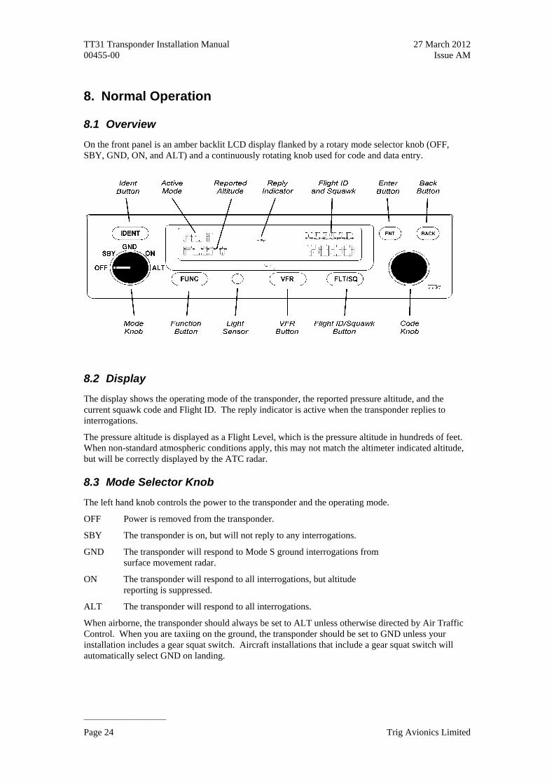
8.1 Overview
On the front panel is an amber backlit LCD display flanked by a rotary mode selector knob (OFF, SBY, GND, ON, and ALT) and a continuously rotating knob used for code and data entry.
8.2 Display
The display shows the operating mode of the transponder, the reported pressure altitude, and the current squawk code and Flight ID. The reply indicator is active when the transponder replies to interrogations.
The pressure altitude is displayed as a Flight Level, which is the pressure altitude in hundreds of feet. When non-standard atmospheric conditions apply, this may not match the altimeter indicated altitude, but will be correctly displayed by the ATC radar.
8.3 Mode Selector Knob
The left hand knob controls the power to the transponder and the operating mode.
OFF Power is removed from the transponder.
SBY The transponder is on, but will not reply to any interrogations.
GND The transponder will respond to Mode S ground interrogations from surface movement radar.
ON The transponder will respond to all interrogations, but altitude reporting is suppressed.
ALT The transponder will respond to all interrogations.
When airborne, the transponder should always be set to ALT unless otherwise directed by Air Traffic Control. When you are taxiing on the ground, the transponder should be set to GND unless your installation includes a gear squat switch. Aircraft installations that include a gear squat switch will automatically select GND on landing.
Page 24 Trig Avionics Limited

TT31 Transponder Installation Manual 27 March 2012 00455-00 Issue AM
______________________
8.4 Push Buttons
IDENT Press the IDENT button when ATC instructs you to “Ident” or “Squawk Ident”. This activates the SPI pulse in the transponder replies for 18 seconds. IDENT will appear in the display.
FUNC Pressing the FUNC button provides access to the flight timer, stopwatch and altitude monitor function. When the aircraft is ADS-B equipped, pressing FUNC also provides access to the ADS-B position monitor.
VFR Pressing the VFR button sets the transponder to the pre-programmed conspicuity code. Pressing the button again restores the previous squawk code.
FLT/SQ Pressing FLT/SQ alternates the primary display between squawk code and Flight ID.
ENT The ENT button enters a digit in the code selector.
BACK The BACK button goes back to the previous digit in the code selector.
8.5 Code Selector Knob
The right hand knob is used to set squawk codes and the Flight ID. The FLT/SQ button selects which will be updated. Turning the knob will highlight the first digit on the display, and the digit can be changed as required. Press the ENT button to advance to the next digit. When ENT is pressed on the last digit, the new squawk code or Flight ID will replace the previous value. If the code entry is not completed within 7 seconds, the changes are ignored and the previous code restored.
1200 VFR code in the USA
7000 VFR code commonly used in Europe.
7500 Hijack code
7600 Loss of communications
7700 Emergency code
The Flight ID should correspond to the aircraft call sign entered on your flight plan. If no flight plan is active, the aircraft registration should be used as your Flight ID. Use only letters and digits. If the Flight ID is less than 8 characters long, entering a blank character will end it.
8.6 Flight Timer
The Flight Timer records the time for which the transponder has been powered on and operating in flight mode – either ON or ALT. Press the FUNC button to display the Flight Timer.
8.7 Stopwatch
The stopwatch can be used as a convenient timer. Press the FUNC button to display the stopwatch. Pressing ENT will reset and start the timer. Pressing ENT again will stop the timer.
8.8 ADS-B Position Monitor
The ADS-B position monitor is available on aircraft equipped for ADS-B position output. It provides a convenient way of verifying that valid position information is being received by the transponder by displaying the current calculated position. If a valid position is displayed, the transponder will be transmitting that position to ADS-B participants. If no position is available the position will be
Trig Avionics Limited Page 25

TT31 Transponder Installation Manual 27 March 2012 00455-00 Issue AM
______________________
displayed as dashes, and the transponder will NOT be transmitting ADS-B position information.
8.9 Altitude Monitor
The Altitude Monitor activates an audio annunciator or annunciator light (depending on installation) when the aircraft pressure altitude differs from the selected altitude by more than 200 feet. Press the FUNC button to display the altitude monitor enable screen. Pressing ENT toggles the altitude monitor at the current altitude.
When altitude monitoring is in use, a small deviation pointer appears adjacent to the altitude display on the transponder.
8.10 Warnings
There are two warning messages that can be displayed on the transponder. Warning messages can be cleared by pressing the ENT key on the control panel.
If the transponder has been configured for ADS-B operation, but a suitable position fix is not available, a warning message is displayed to indicate that ADS-B capability has been lost. The transponder will continue to operate normally.
If there is a problem with the antenna installation, a warning message may be displayed. Depending on whether this is an intermittent problem the message may recur when cleared. The transponder may still be replying to interrogations, but there can be no assurance that ATC is receiving those replies.
8.11 Fault Annunciation
If the transponder detects an internal failure, or a hard fault with the antenna installation, the screen will indicate FAULT and a brief statement of the problem. No replies will be made to interrogations when a fault is detected.
8.12 Low Temperature Operation
The TT31 is certified for correct operation at temperatures down to -20 Celsius. At low temperatures however the display performance will be impaired. The aircraft cockpit should be warmed to allow normal operation of the transponder before takeoff.
Page 26 Trig Avionics Limited

TT31 Transponder Installation Manual 27 March 2012 00455-00 Issue AM
______________________
9. Continued Airworthiness
Other than for periodic functional checks required by the regulations, the TT31 Mode S transponder has been designed and manufactured to allow “on condition maintenance”. This means that there are no periodic service requirements necessary to maintain continued airworthiness, and no maintenance is required until the equipment does not properly perform its intended function. When service is required, a complete performance test should be accomplished following any repair action. Repairs should only be carried out in accordance with Trig Avionics Limited service procedures.
Trig Avionics Limited Page 27

TT31 Transponder Installation Manual 27 March 2012 00455-00 Issue AM
______________________
10. Limited Warranty
Trig Avionics Limited warrants our products to be free from defects in materials and workmanship for a period of two (2) years from the date of installation by an authorised dealer.
This warranty covers repair and/or replacement at our option, of any parts found to be defective, provided such defects in our opinion are due to faulty material or workmanship and are not caused by tampering, abuse, or normal wear.
All warranties are F.O.B.
Trig Avionics Limited Heriot Watt Research Park Riccarton, Currie, EH14 4AP
Trig Avionics will not accept or pay for any charges for warranty work performed outside our factory without prior written consent.
This warranty applies only to products in normal use. It does not apply to units or circuit boards defective due to improper installation, physical damage, tampering, lightning or other electrical discharge, units with altered serial numbers, or units repaired by unauthorised persons or in violation of Trig Avionics Limited service procedures.
Trig Avionics Limited assumes no responsibility for any consequential losses of any nature with respect to any products or services sold, rendered, or delivered.
Page 28 Trig Avionics Limited

TT31 Transponder Installation Manual 27 March 2012 00455-00 Issue AM
______________________
11. Environmental Qualification Form
Nomenclature TT31 Mode S Transponder
Part Number: 00220-(XX) ETSO: 2C112b
Manufacturer Trig Avionics Limited
Address Heriot Watt Research Park, Riccarton, Currie, Scotland, EH14 4AP
Conditions DO-160D Section
Description of Conducted Tests
Temperature and Altitude 4.0 Equipment tested to Categories A1, C1
Low temperature ground survival 4.5.1 -55°C
Low temperature operating 4.5.1 -20°C
High temperature operating 4.5.3 +55°C
High temperature short-time operating 4.5.2 +70°C
High temperature ground survival 4.5.2 +85°C
Loss of Cooling 4.5.4 Cooling air not required (+70°C operating without cooling air)
Altitude 4.6.1 35,000 feet
Decompression 4.6.2 8,000 to 35,000 feet in 15 seconds
Overpressure 4.6.3 -15000 feet
Temperature Variation 5.0 Equipment tested to Category C
Humidity 6.0 Equipment tested to Category A
Operational Shocks 7.2 Equipment tested to Category B
Crash Safety 7.3 Equipment tested to Category B and extended to use test levels for Helicopters
Vibration 8.0 Aircraft zone 2; type 3, 4, 5 to category S level M
Equipment at strike-off level 3 also tested for aircraft zone 2; type 1 (Helicopters) to category U level G
Explosion 9.0 Equipment identified as Category X – no test required
Waterproofness 10.0 Equipment identified as Category X – no test required
Fluids Susceptibility 11.0 Equipment identified as Category X – no test required
Sand and Dust 12.0 Equipment identified as Category X – no test required
Fungus 13.0 Equipment identified as Category X – no test required
Salt Spray 14.0 Equipment identified as Category X – no test required
Magnetic Effect 15.0 Equipment tested to Category Z
Power Input 16.0 Equipment tested to Category B
Voltage Spike 17.0 Equipment tested to Category B
Audio frequency conducted susceptibility 18.0 Equipment tested to Category B
Induced signal susceptibility 19.0 Equipment tested to Category A
Radio frequency susceptibility 20.0 Equipment tested to Category T
Radio frequency emission 21.0 Equipment tested to Category B
Lightning induced transient susceptibility 22.0 Equipment identified as Category XXXX – no test required
Lightning direct effects 23.0 Equipment identified as Category X – no test required
Icing 24.0 Equipment identified as Category X – no test required
Electrostatic Discharge 25.0 Equipment identified as Category X – no test required
Trig Avionics Limited Page 29
TT31 Transponder Installation Manual 27 March 2012 00455-00 Issue AM
______________________
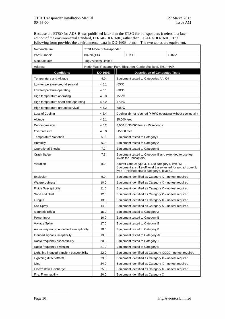
Because the ETSO for ADS-B was published later than the ETSO for transponders it refers to a later edition of the environmental standard, ED-14E/DO-160E, rather than ED-14D/DO-160D. The following form provides the environmental data in DO-160E format. The two tables are equivalent.
Nomenclature TT31 Mode S Transponder
Part Number: 00220-(XX) ETSO: C166a
Manufacturer Trig Avionics Limited
Address Heriot Watt Research Park, Riccarton, Currie, Scotland, EH14 4AP
Conditions DO-160E Description of Conducted Tests
Temperature and Altitude 4.0 Equipment tested to Categories A4, C4
Low temperature ground survival 4.5.1 -55°C
Low temperature operating 4.5.1 -20°C
High temperature operating 4.5.3 +55°C
High temperature short-time operating 4.5.2 +70°C
High temperature ground survival 4.5.2 +85°C
Loss of Cooling 4.5.4 Cooling air not required (+70°C operating without cooling air)
Altitude 4.6.1 35,000 feet
Decompression 4.6.2 8,000 to 35,000 feet in 15 seconds
Overpressure 4.6.3 -15000 feet
Temperature Variation 5.0 Equipment tested to Category C
Humidity 6.0 Equipment tested to Category A
Operational Shocks 7.2 Equipment tested to Category B
Crash Safety 7.3 Equipment tested to Category B and extended to use test levels for Helicopters
Vibration 8.0 Aircraft zone 2; type 3, 4, 5 to category S level M Equipment at strike-off level 3 also tested for aircraft zone 2; type 1 (Helicopters) to category U level G
Explosion 9.0 Equipment identified as Category X – no test required
Waterproofness 10.0 Equipment identified as Category X – no test required
Fluids Susceptibility 11.0 Equipment identified as Category X – no test required
Sand and Dust 12.0 Equipment identified as Category X – no test required
Fungus 13.0 Equipment identified as Category X – no test required
Salt Spray 14.0 Equipment identified as Category X – no test required
Magnetic Effect 15.0 Equipment tested to Category Z
Power Input 16.0 Equipment tested to Category B
Voltage Spike 17.0 Equipment tested to Category B
Audio frequency conducted susceptibility 18.0 Equipment tested to Category B
Induced signal susceptibility 19.0 Equipment tested to Category AC
Radio frequency susceptibility 20.0 Equipment tested to Category T
Radio frequency emission 21.0 Equipment tested to Category B
Lightning induced transient susceptibility 22.0 Equipment identified as Category XXXX – no test required
Lightning direct effects 23.0 Equipment identified as Category X – no test required
Icing 24.0 Equipment identified as Category X – no test required
Electrostatic Discharge 25.0 Equipment identified as Category X – no test required
Fire, Flammability 26.0 Equipment identified as Category C
Page 30 Trig Avionics Limited

TT31 Transponder Installation Manual 27 March 2012 00455-00 Issue AM
______________________
12. ADS-B Compliance
TT31 transponders with software version 3.1 and above include support for Extended Squitter ADS-B out which is compliant with DO-260B. The TT31 is a B1S ADS-B transmitter.
12.1 ADS-B Parameters Supported
The following table lists the ADS-B parameters that are transmitted by the TT31 transponder when connected to an appropriate GPS receiver.
Parameter BDS Register
SPI 0,5
Emergency Indicator 0,5
Barometric Altitude 0,5
Quality Indicator (NIC) 0,5
Latitude 0,5 Airborne Position
Longitude 0,5
Quality Indicator (NIC) 0,6
Latitude 0,6 Surface Position
Longitude 0,6
Surface Ground Speed 0,6
Surface Ground Track 0,6
Aircraft Identification 0,8
Airborne Ground Velocity 0,9
Geometric to Barometric Altitude Difference 0.9
Geometric Vertical Speed 0.9
Squawk Code 6,1
Emergency Status 6,1
Quality Indicator (NACp, NACv and GVA) 6,5
Quality Indicator (SIL and SDA) 6,5
Version Indicator 6,5
Surface Length/Width 6,5
Surface Antenna Offset 6,5
In all cases, uncompensated latency due to the transponder is less than 10 milliseconds. Analysis of the system latency should add this to the latency of the GPS system and the transmission time of the position data from the GPS to the transponder to determine the overall latency.
12.2 FAA 91.227 Compliance
The TT31 transponder can be connected to the following GPS units to form the basis of a 14 CFR 91.227 compliant ADS-B installation:
Trig Avionics Limited Page 31

TT31 Transponder Installation Manual 27 March 2012 00455-00 Issue AM
______________________
Page 32 Trig Avionics Limited
Freeflight 1201 & 1204 WAAS/GPS Sensors
NexNav MINI & NexNav MAX WAAS/GPS Sensors
Garmin GNS 400W/500W series
For installations seeking certification to 91.227 or other applicable standards, additional compliance information is available on request from Trig Avionics Limited.
12.3 AMC 20-24 Compliance
The TT31 transponder can be connected to the following GPS units to form the basis of an AMC 20-24 compliant ADS-B installation:
Freeflight 1201 & 1204 WAAS/GPS Sensors
NexNav MINI & NexNav MAX WAAS/GPS Sensors
Garmin GNS 400W/500W series
For installations seeking certification to AMC 20-24 or other applicable standards, additional compliance information is available on request from Trig Avionics Limited.
12.4 Automatic Air/Ground Determination
The TT31 can report ADS-B surface and airborne messages. The ADC or squat switch inputs can be utilised to determine air/ground status as explained in section 5.
12.5 ADS-B Support
If you require additional information and data to support an ADS-B installation then please contact [email protected].
TT31 Transponder Installation Manual 27 March 2012 00455-00 Issue AM
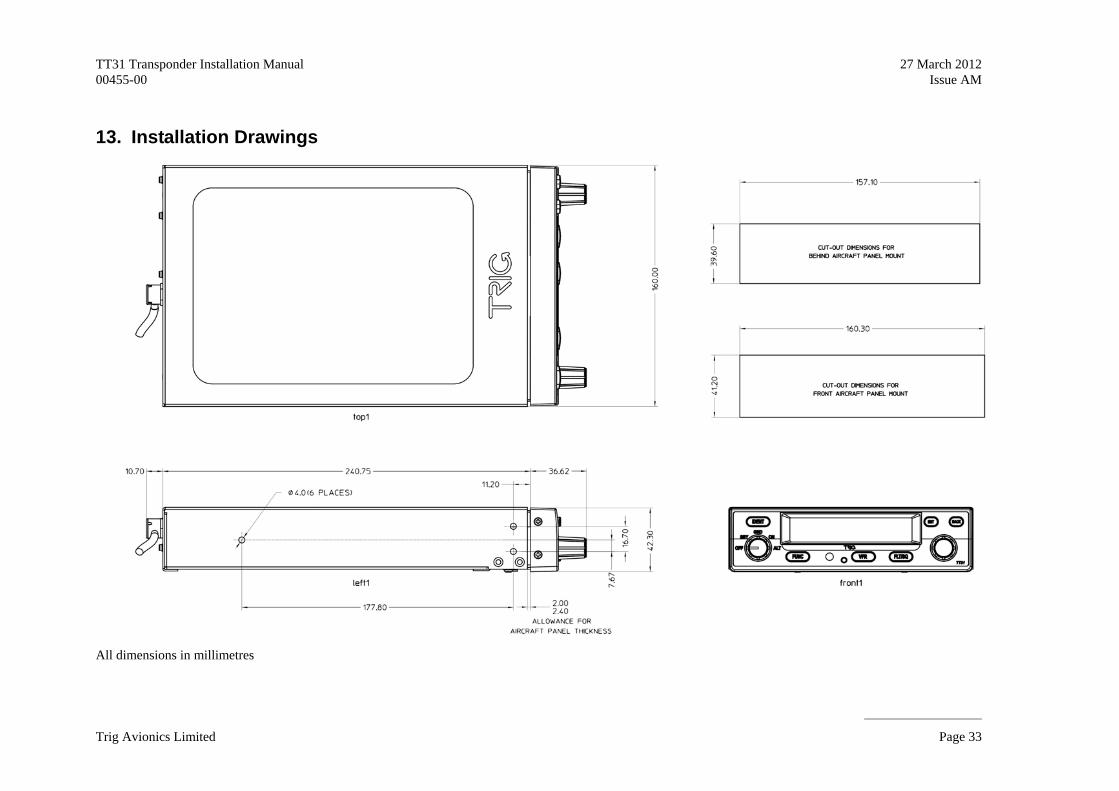
13. Installation Drawings
All dimensions in millimetres
______________________
Trig Avionics Limited Page 33

TT31 Transponder Installation Manual 27 March 2012 Issue AM
______________________
Page 34 Trig Avionics Limited
Trig Avionics Limited
00455-00
14. Basic Interconnect Diagram 14. Basic Interconnect Diagram
TRIG
TT3
1 MOD
E S
TRAN
SPON
DER
Ground Lighting 14V Lighting 28V
Suppress I/O Squat Switch
Serial Alt Out Serial Alt In Suppress In Ext Standby
11-33V DC 11-33V DC
Ground
Ext Ident
Alt D4 Alt B4 Alt B2 Alt C1 Alt B1 Alt C4 Alt A4 Alt A2 Alt C2 Alt A1
Test
Ground
TIS Output GPS Input Reserved
Audio Mute
Alt Alert Ground
Audio + Audio –
Reserved Reserved Reserved
RF
1 2 3 4 5
6 7 9
10
11 12 A
F
8 B C D E H J K L M
N
1
2 3 4 5
6 A
B C D E F
Coax
GPS
POSITION SOURCE MUTUAL SUPPRESSION BUS
PARALLEL ALTITUDE ENCODER
SERIAL ALTITUDE ENCODER
or ADC
3A
CIRCUIT BREAKER
11 – 33V
1
ALL WIRES SHOULD BE 18 – 24 AWG
2
ONLY CONNECT ONE ALTITUDE DATA SOURCE, EITHER A SERIAL ENCODER, PARALLEL ENCODER OR ADC.
NOTES: 1.
WHEN USING DATA FROM AN ADC, IT SHOULD BE CONNECTED TO THE “SERIAL ALT IN”, AS SHOWN.
1
1 2
3 CONNECT ONLY ONE INPUT TO THE LIGHTING BUS, DEPENDING ON LINE VOLTAGE
LAMP SHOWN AS EXAMPLE OF POSSIBLE ALERTER INSTALLATION. OTHER OPTIONS ARE POSSIBLE. 4
DME
OTHER TRANSPONDER
TRAFFIC DISPLAY
1A
CIRCUIT BREAKER
LAMP
AUDIO PANEL
3
4 11 – 33V

TT31 Transponder Installation Manual 00455-00
This page intentionally left blank
Trig Avionics Limited