ts 133 102 - v14.1.0 - digital cellular … · 6.8 interoperation and handover between umts and gsm...
TRANSCRIPT
ETSI TS 133 102 V14.1.0 (2017-03)
Digital cellular telecommunications system (Phase 2+) (GSM); Universal Mobile Telecommunications System (UMTS);
3G security; Security architecture
(3GPP TS 33.102 version 14.1.0 Release 14)
TECHNICAL SPECIFICATION
GLOBAL SYSTEM FOR MOBILE COMMUNICATIONS
R
ETSI
ETSI TS 133 102 V14.1.0 (2017-03)13GPP TS 33.102 version 14.1.0 Release 14
Reference RTS/TSGS-0333102ve10
Keywords GSM,SECURITY,UMTS
ETSI
650 Route des Lucioles F-06921 Sophia Antipolis Cedex - FRANCE
Tel.: +33 4 92 94 42 00 Fax: +33 4 93 65 47 16
Siret N° 348 623 562 00017 - NAF 742 C
Association à but non lucratif enregistrée à la Sous-Préfecture de Grasse (06) N° 7803/88
Important notice
The present document can be downloaded from: http://www.etsi.org/standards-search
The present document may be made available in electronic versions and/or in print. The content of any electronic and/or print versions of the present document shall not be modified without the prior written authorization of ETSI. In case of any
existing or perceived difference in contents between such versions and/or in print, the only prevailing document is the print of the Portable Document Format (PDF) version kept on a specific network drive within ETSI Secretariat.
Users of the present document should be aware that the document may be subject to revision or change of status. Information on the current status of this and other ETSI documents is available at
https://portal.etsi.org/TB/ETSIDeliverableStatus.aspx
If you find errors in the present document, please send your comment to one of the following services: https://portal.etsi.org/People/CommiteeSupportStaff.aspx
Copyright Notification
No part may be reproduced or utilized in any form or by any means, electronic or mechanical, including photocopying and microfilm except as authorized by written permission of ETSI.
The content of the PDF version shall not be modified without the written authorization of ETSI. The copyright and the foregoing restriction extend to reproduction in all media.
© European Telecommunications Standards Institute 2017.
All rights reserved.
DECTTM, PLUGTESTSTM, UMTSTM and the ETSI logo are Trade Marks of ETSI registered for the benefit of its Members. 3GPPTM and LTE™ are Trade Marks of ETSI registered for the benefit of its Members and
of the 3GPP Organizational Partners. GSM® and the GSM logo are Trade Marks registered and owned by the GSM Association.
ETSI
ETSI TS 133 102 V14.1.0 (2017-03)23GPP TS 33.102 version 14.1.0 Release 14
Intellectual Property Rights IPRs essential or potentially essential to the present document may have been declared to ETSI. The information pertaining to these essential IPRs, if any, is publicly available for ETSI members and non-members, and can be found in ETSI SR 000 314: "Intellectual Property Rights (IPRs); Essential, or potentially Essential, IPRs notified to ETSI in respect of ETSI standards", which is available from the ETSI Secretariat. Latest updates are available on the ETSI Web server (https://ipr.etsi.org/).
Pursuant to the ETSI IPR Policy, no investigation, including IPR searches, has been carried out by ETSI. No guarantee can be given as to the existence of other IPRs not referenced in ETSI SR 000 314 (or the updates on the ETSI Web server) which are, or may be, or may become, essential to the present document.
Foreword The present document may refer to technical specifications or reports using their 3GPP identities, UMTS identities or GSM identities. These should be interpreted as being references to the corresponding ETSI deliverables.
The cross reference between GSM, UMTS, 3GPP and ETSI identities can be found under http://webapp.etsi.org/key/queryform.asp.
Modal verbs terminology In the present document "shall", "shall not", "should", "should not", "may", "need not", "will", "will not", "can" and "cannot" are to be interpreted as described in clause 3.2 of the ETSI Drafting Rules (Verbal forms for the expression of provisions).
"must" and "must not" are NOT allowed in ETSI deliverables except when used in direct citation.
ETSI
ETSI TS 133 102 V14.1.0 (2017-03)33GPP TS 33.102 version 14.1.0 Release 14
Contents
Intellectual Property Rights ................................................................................................................................ 2
Foreword ............................................................................................................................................................. 2
Modal verbs terminology .................................................................................................................................... 2
Foreword ............................................................................................................................................................. 7
1 Scope ........................................................................................................................................................ 8
2 References ................................................................................................................................................ 8
3 Definitions, symbols abbreviations and conventions ............................................................................. 10
3.1 Definitions ........................................................................................................................................................ 10
3.2 Symbols ............................................................................................................................................................ 11
3.3 Abbreviations ................................................................................................................................................... 11
3.4 Conventions ...................................................................................................................................................... 12
4 Overview of the security architecture..................................................................................................... 12
5 Security features ..................................................................................................................................... 14
5.1 Network access security ................................................................................................................................... 14
5.1.1 User identity confidentiality ....................................................................................................................... 14
5.1.2 Entity authentication ................................................................................................................................... 14
5.1.3 Confidentiality ............................................................................................................................................ 14
5.1.4 Data integrity .............................................................................................................................................. 15
5.1.5 Mobile equipment identification ................................................................................................................. 15
5.2 Network domain security ................................................................................................................................. 15
5.2.1 Void ............................................................................................................................................................ 15
5.2.2 Void ............................................................................................................................................................ 15
5.2.3 Void ............................................................................................................................................................ 15
5.2.4 Fraud information gathering system ........................................................................................................... 16
5.3 User domain security ........................................................................................................................................ 16
5.3.1 User-to-USIM authentication...................................................................................................................... 16
5.3.2 USIM-Terminal Link .................................................................................................................................. 16
5.4 Application security ......................................................................................................................................... 16
5.4.1 Secure messaging between the USIM and the network .............................................................................. 16
5.4.2 Void ............................................................................................................................................................ 16
5.4.3 Void ............................................................................................................................................................ 16
5.4.4 Void ............................................................................................................................................................ 16
5.5 Security visibility and configurability .............................................................................................................. 17
5.5.1 Visibility ..................................................................................................................................................... 17
5.5.2 Configurability ............................................................................................................................................ 17
6 Network access security mechanisms .................................................................................................... 17
6.1 Identification by temporary identities............................................................................................................... 17
6.1.1 General ........................................................................................................................................................ 17
6.1.2 TMSI reallocation procedure ...................................................................................................................... 18
6.1.3 Unacknowledged allocation of a temporary identity .................................................................................. 18
6.1.4 Location update .......................................................................................................................................... 18
6.2 Identification by a permanent identity .............................................................................................................. 19
6.3 Authentication and key agreement ................................................................................................................... 19
6.3.1 General ........................................................................................................................................................ 19
6.3.2 Distribution of authentication data from HE to SN .................................................................................... 21
6.3.3 Authentication and key agreement .............................................................................................................. 23
6.3.4 Distribution of IMSI and temporary authentication data within one serving network domain ................... 26
6.3.5 Re-synchronisation procedure .................................................................................................................... 27
6.3.6 Reporting authentication failures from the SGSN/VLR to the HLR .......................................................... 28
6.3.6.1 Authentication re-attempt ...................................................................................................................... 28
6.3.7 Length of authentication parameters ........................................................................................................... 29
6.4 Local authentication and connection establishment ......................................................................................... 29
ETSI
ETSI TS 133 102 V14.1.0 (2017-03)43GPP TS 33.102 version 14.1.0 Release 14
6.4.1 Cipher key and integrity key setting ........................................................................................................... 29
6.4.2 Ciphering and integrity mode negotiation .................................................................................................. 29
6.4.3 Cipher key and integrity key lifetime ......................................................................................................... 30
6.4.4 Cipher key and integrity key identification ................................................................................................. 30
6.4.5 Security mode set-up procedure .................................................................................................................. 31
6.4.6 Signalling procedures in the case of an unsuccessful integrity check ......................................................... 34
6.4.7 Signalling procedure for periodic local authentication ............................................................................... 34
6.4.8 Initialisation of synchronisation for ciphering and integrity protection ...................................................... 34
6.4.9 Emergency call handling ............................................................................................................................ 35
6.4.9.1 Security procedures applied .................................................................................................................. 35
6.4.9.2 Security procedures not applied ............................................................................................................ 35
6.5 Access link data integrity ................................................................................................................................. 36
6.5.1 General ........................................................................................................................................................ 36
6.5.2 Layer of integrity protection ....................................................................................................................... 36
6.5.3 Data integrity protection method ................................................................................................................ 36
6.5.4 Input parameters to the integrity algorithm ................................................................................................. 37
6.5.4.1 COUNT-I .............................................................................................................................................. 37
6.5.4.2 IK .......................................................................................................................................................... 37
6.5.4.3 FRESH .................................................................................................................................................. 37
6.5.4.4 DIRECTION ......................................................................................................................................... 38
6.5.4.5 MESSAGE ............................................................................................................................................ 38
6.5.5 Integrity key selection ................................................................................................................................. 38
6.5.6 UIA identification ....................................................................................................................................... 38
6.6 Access link data confidentiality ........................................................................................................................ 39
6.6.1 General ........................................................................................................................................................ 39
6.6.2 Layer of ciphering ....................................................................................................................................... 39
6.6.3 Ciphering method ....................................................................................................................................... 39
6.6.4 Input parameters to the cipher algorithm .................................................................................................... 40
6.6.4.1 COUNT-C ............................................................................................................................................. 40
6.6.4.2 CK ......................................................................................................................................................... 40
6.6.4.3 BEARER ............................................................................................................................................... 41
6.6.4.4 DIRECTION ......................................................................................................................................... 41
6.6.4.5 LENGTH ............................................................................................................................................... 41
6.6.5 Cipher key selection.................................................................................................................................... 41
6.6.6 UEA identification ...................................................................................................................................... 42
6.7 Void .................................................................................................................................................................. 42
6.8 Interoperation and handover between UMTS and GSM .................................................................................. 42
6.8.1 Authentication and key agreement of UMTS subscribers .......................................................................... 42
6.8.1.1 General .................................................................................................................................................. 42
6.8.1.2 R99+ HLR/AuC .................................................................................................................................... 43
6.8.1.3 R99+ VLR/SGSN ................................................................................................................................. 44
6.8.1.4 R99+ ME ............................................................................................................................................... 45
6.8.1.5 USIM ..................................................................................................................................................... 45
6.8.2 Authentication and key agreement for GSM subscribers............................................................................ 46
6.8.2.1 General .................................................................................................................................................. 46
6.8.2.2 R99+ HLR/AuC .................................................................................................................................... 47
6.8.2.3 VLR/SGSN ........................................................................................................................................... 47
6.8.2.4 R99+ ME ............................................................................................................................................... 48
6.8.3 Distribution and use of authentication data between VLRs/SGSNs ........................................................... 48
6.8.4 Intersystem handover for CS Services – from UTRAN to GSM BSS ........................................................ 49
6.8.4.1 UMTS security context ......................................................................................................................... 49
6.8.4.2 GSM security context ............................................................................................................................ 50
6.8.5 Intersystem handover for CS Services – from GSM BSS to UTRAN ........................................................ 50
6.8.5.1 UMTS security context ......................................................................................................................... 50
6.8.5.2 GSM security context ............................................................................................................................ 51
6.8.6 Intersystem change for PS Services – from UTRAN to GSM BSS ............................................................ 51
6.8.6.1 UMTS security context ......................................................................................................................... 51
6.8.6.2 GSM security context ............................................................................................................................ 52
6.8.7 Intersystem change for PS services – from GSM BSS to UTRAN............................................................. 52
6.8.7.1 UMTS security context ......................................................................................................................... 52
6.8.7.2 GSM security context ............................................................................................................................ 52
6.8.8 PS handover from Iu to Gb mode ............................................................................................................... 53
ETSI
ETSI TS 133 102 V14.1.0 (2017-03)53GPP TS 33.102 version 14.1.0 Release 14
6.8.8.1 UMTS security context ......................................................................................................................... 53
6.8.8.2 GSM security context ............................................................................................................................ 53
6.8.9 PS handover from Gb to Iu mode ............................................................................................................... 54
6.8.9.1 UMTS security context ......................................................................................................................... 54
6.8.9.2 GSM security context ............................................................................................................................ 54
6.8.10 SRVCC – between HSPA and UTRAN/GERAN ...................................................................................... 54
6.8.10.1 SRVCC from HSPA to circuit switched UTRAN/GERAN .................................................................. 54
6.8.10.2 SRVCC from circuit switched GERAN to HSPA ................................................................................. 56
6.8.11 Handling of the START value in intersystem mobility cases ..................................................................... 58
7 Void ........................................................................................................................................................ 59
8 Application security mechanisms ........................................................................................................... 59
8.1 Void .................................................................................................................................................................. 59
8.2 Void .................................................................................................................................................................. 59
8.3 Mobile IP security ............................................................................................................................................ 59
Annex A: Void ................................................................................................................. 60
Annex B (normative): Key derivation function ................................................................................. 61
B.1 General ................................................................................................................................................... 61
B.2 FC value allocations ............................................................................................................................... 61
B.3 Derivation of CK’CS|| IK’CS from CKPS||IKPS.......................................................................................... 61
B.4 Derivation of Kc’ from Kc for HSPA to UTRAN/GERAN SRVCC handover ..................................... 61
B.5 Derivation of Kc128 ................................................................................................................................. 61
B.6 Derivation of CK'PS || IK'PS from CKCS || IKCS......................................................................................... 62
B.7 Derivation of Kc' from Kc for UTRAN/GERAN to HSPA SRVCC handover ..................................... 62
Annex C (informative): Management of sequence numbers .............................................................. 63
C.1 Generation of sequence numbers in the Authentication Centre ............................................................. 63
C.1.1 Sequence number generation schemes ............................................................................................................. 63
C.1.1.1 General scheme ........................................................................................................................................... 63
C.1.1.2 Generation of sequence numbers which are not time-based ....................................................................... 64
C.1.1.3 Time-based sequence number generation ................................................................................................... 64
C.1.2 Support for the array mechanism ..................................................................................................................... 64
C.2 Handling of sequence numbers in the USIM ......................................................................................... 64
C.2.1 Protection against wrap around of counter in the USIM .................................................................................. 65
C.2.2 Verification of sequence number freshness in the USIM ................................................................................. 65
C.2.3 Notes ................................................................................................................................................................ 65
C.3 Sequence number management profiles ................................................................................................. 66
C.3.1 Profile 1: management of sequence numbers which are partly time-based ...................................................... 66
C.3.2 Profile 2: management of sequence numbers which are not time-based .......................................................... 67
C.3.3 Profile 3: management of sequence numbers which are entirely time-based ................................................... 67
C.3.4 Guidelines for the allocation of the index values in the array scheme ............................................................. 68
C.4 Guidelines for interoperability in a multi-vendor environment .............................................................. 68
Annex D: Void ........................................................................................................................................ 69
Annex E: Void ........................................................................................................................................ 70
Annex F (informative): Example uses of the proprietary part of the AMF ..................................... 71
F.1 Support multiple authentication algorithms and keys ............................................................................ 71
F.2 Changing sequence number verification parameters .............................................................................. 71
F.3 Setting threshold values to restrict the lifetime of cipher and integrity keys ......................................... 71
ETSI
ETSI TS 133 102 V14.1.0 (2017-03)63GPP TS 33.102 version 14.1.0 Release 14
Annex G (normative): Support of algorithm change features.......................................................... 72
Annex H (normative): Usage of the AMF .......................................................................................... 73
Annex I (normative): Security requirements for RNCs in exposed locations ............................... 74
I.1 General ................................................................................................................................................... 74
I.2 Requirements for RNCs in exposed locations ........................................................................................ 74
I.2.1 Requirements for setup and configuration ........................................................................................................ 74
I.2.2 Requirements for key management inside RNCs in exposed locations ........................................................... 74
I.2.3 Requirements for handling user plane data ...................................................................................................... 75
I.2.4 Requirements for handling control plane data .................................................................................................. 75
I.2.5 Requirements for secure environment .............................................................................................................. 75
I.3 Security mechanisms for interfaces with RNCs in exposed locations ................................................... 75
Annex J (informative): Change history ............................................................................................... 77
History .............................................................................................................................................................. 79
ETSI
ETSI TS 133 102 V14.1.0 (2017-03)73GPP TS 33.102 version 14.1.0 Release 14
Foreword This Technical Specification (TS) has been produced by ETSI 3rd Generation Partnership Project (3GPP).
The contents of the present document are subject to continuing work within the TSG and may change following formal TSG approval. Should the TSG modify the contents of the present document, it will be re-released by the TSG with an identifying change of release date and an increase in version number as follows:
Version x.y.z
where:
x the first digit:
1 presented to TSG for information;
2 presented to TSG for approval;
3 or greater indicates TSG approved document under change control.
y the second digit is incremented for all changes of substance, i.e. technical enhancements, corrections, updates, etc.
z the third digit is incremented when editorial only changes have been incorporated in the document.
ETSI
ETSI TS 133 102 V14.1.0 (2017-03)83GPP TS 33.102 version 14.1.0 Release 14
1 Scope This specification defines the security architecture, i.e., the security features and the security mechanisms, for the third generation mobile telecommunication system.
A security feature is a service capability that meets one or several security requirements. The complete set of security features address the security requirements as they are defined in "3G Security: Threats and Requirements" (TS 21.133 [1]) and implement the security objectives and principles described in TS 33.120 [2]. A security mechanism is an element that is used to realise a security feature. All security features and security mechanisms taken together form the security architecture.
An example of a security feature is user data confidentiality. A security mechanism that may be used to implement that feature is a stream cipher using a derived cipher key.
This specification defines 3G security procedures performed within 3G capable networks (R99+), i.e. intra-UMTS and UMTS-GSM. As an example, UMTS authentication is applicable to UMTS radio access as well as GSM radio access provided that the serving network node and the MS are UMTS capable. Interoperability with non-UMTS capable networks (R98-) is also covered.
GSM security functions are defined in the TS 43.020 [36].
2 References The following documents contain provisions which, through reference in this text, constitute provisions of the present document.
- References are either specific (identified by date of publication, edition number, version number, etc.) or non-specific.
- For a specific reference, subsequent revisions do not apply.
- For a non-specific reference, the latest version applies. In the case of a reference to a 3GPP document (including a GSM document), a non-specific reference implicitly refers to the latest version of that document in the same Release as the present document.
[1] 3GPP TS 21.133: "3G Security; Security Threats and Requirements".
[2] 3GPP TS 33.120: "3G Security; Security Principles and Objectives".
[3] 3GPP TR 21.905: "Vocabulary for 3GPP Specifications (Release 1999)".
[4] 3GPP TS 23.121: "Architecture Requirements for Release 99".
[5] 3GPP TS 31.101: "UICC-terminal interface; Physical and logical characteristics".
[6] 3GPP TS 22.022: "Personalisation of UMTS Mobile Equipment (ME); Mobile functionality specification".
[7] 3GPP TS 23.048: "Security Mechanisms for the (U)SIM application toolkit; Stage 2".
[8] 3GPP TS 43.020: "Security related network functions".
[9] 3GPP TS 23.060: "General Packet Radio Service (GPRS); Service description; Stage 2".
[10] ISO/IEC 9798-4: "Information technology - Security techniques - Entity authentication - Part 4: Mechanisms using a cryptographic check function".
[11] 3GPP TS 35.201: "Specification of the 3GPP confidentiality and integrity algorithms; Document 1: f8 and f9 specifications".
[12] 3GPP TS 35.202: "Specification of the 3GPP confidentiality and integrity algorithms; Document 2: Kasumi algorithm specification".
ETSI
ETSI TS 133 102 V14.1.0 (2017-03)93GPP TS 33.102 version 14.1.0 Release 14
[13] 3GPP TS 35.203: "Specification of the 3GPP confidentiality and integrity algorithms; Document 3: Implementers' test data".
[14] 3GPP TS 35.204: "Specification of the 3GPP confidentiality and integrity algorithms; Document 4: Design conformance test data".
[15] 3GPP TS 31.111: "USIM Application Toolkit (USAT)".
[16] 3GPP TS 22.048: "Security Mechanisms for the (U)SIM Application Toolkit; Stage 1".
[17] 3GPP TS 25.331: "Radio Resource Control (RRC); Protocol specification".
[18] 3GPP TS 25.321: "Medium Access Control (MAC) protocol specification".
[19] 3GPP TS 25.322: "Radio Link Control (RLC) protocol specification".
[20] 3GPP TS 31.102: "Characteristics of the Universal Subscriber Identity Module (USIM) application".
[21] 3GPP TS 22.101: "Service aspects; Service principles".
[22] 3GPP TS 23.195: "Provision of User Equipment Specific Behaviour Information (UESBI) to network entities".
[23] 3GPP TS 43.129: "Packed-switched handover for GERAN A/Gb mode; Stage 2".
[24] 3GPP TS 35.215: "Specification of the 3GPP Confidentiality and Integrity Algorithms UEA2 & UIA2; Document 1: UEA2 and UIA2 specifications".
[25] 3GPP TS 35.216: "Specification of the 3GPP Confidentiality and Integrity Algorithms UEA2 & UIA2; Document 2: SNOW 3G specification".
[26] 3GPP TS 35.217: "Specification of the 3GPP Confidentiality and Integrity Algorithms UEA2 & UIA2; Document 3: Implementors’ test data".
[27] 3GPP TS 35.218: "Specification of the 3GPP Confidentiality and Integrity Algorithms UEA2 & UIA2; Document 4: Design conformance test data".
[28] 3GPP TS 33.401: "3GPP System Architecture Evolution: Security architecture".
[29] 3GPP TS 33.402: "3GPP System Architecture Evolution: Security aspects of non 3GPP accesses".
[30] 3GPP TS 33.220: "Generic Authentication Architecture (GAA); Generic bootstrapping architecture".
[31] 3GPP TS 25.413: "UTRAN Iu interface RANAP signalling".
[32] 3GPP TS 22.003: "Circuit Teleservices supported by a Public Land Mobile Network (PLMN)".
[33] 3GPP TS 22.101: "Service aspects; Service principles".
[34] 3GPP TS 23.167: " IP Multimedia Subsystem (IMS) emergency sessions".
[35] 3GPP TS 24.008: " Mobile radio interface Layer 3 specification; Core network protocols; Stage 3".
[36] 3GPP TS 43.020: "Security related network functions".
[37] 3GPP TS 23.216: "Single Radio Voice Call Continuity (SRVCC); Stage 2".
[38] 3GPP TS 25.420: "UTRAN Iur interface general aspects and principles".
[39] 3GPP TS 33.210: "3G security; Network Domain Security (NDS); IP network layer security".
[40] 3GPP TS 33.310: "Network Domain Security (NDS); Authentication Framework (AF)".
[41] RFC 4301: "Security Architecture for the Internet Protocol".
ETSI
ETSI TS 133 102 V14.1.0 (2017-03)103GPP TS 33.102 version 14.1.0 Release 14
3 Definitions, symbols abbreviations and conventions
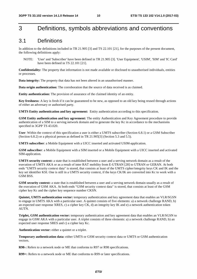
3.1 Definitions In addition to the definitions included in TR 21.905 [3] and TS 22.101 [21], for the purposes of the present document, the following definitions apply:
NOTE: 'User' and 'Subscriber' have been defined in TR 21.905 [3]. 'User Equipment', 'USIM', 'SIM' and 'IC Card' have been defined in TS 22.101 [21].
Confidentiality: The property that information is not made available or disclosed to unauthorised individuals, entities or processes.
Data integrity: The property that data has not been altered in an unauthorised manner.
Data origin authentication: The corroboration that the source of data received is as claimed.
Entity authentication: The provision of assurance of the claimed identity of an entity.
Key freshness: A key is fresh if it can be guaranteed to be new, as opposed to an old key being reused through actions of either an adversary or authorised party.
UMTS Entity authentication and key agreement: Entity authentication according to this specification.
GSM Entity authentication and key agreement: The entity Authentication and Key Agreement procedure to provide authentication of a SIM to a serving network domain and to generate the key Kc in accordance to the mechanisms specified in 3GPP TS 43.020.
User: Within the context of this specification a user is either a UMTS subscriber (Section 6.8.1) or a GSM Subscriber (Section 6.8.2) or a physical person as defined in TR 21.905[3] (Section 5.3 and 5.5).
UMTS subscriber: a Mobile Equipment with a UICC inserted and activated USIM-application.
GSM subscriber: a Mobile Equipment with a SIM inserted or a Mobile Equipment with a UICC inserted and activated SIM-application.
UMTS security context: a state that is established between a user and a serving network domain as a result of the execution of UMTS AKA or as a result of inter RAT mobility from E-UTRAN [28] to UTRAN or GERAN. At both ends "UMTS security context data" is stored, that consists at least of the UMTS cipher/integrity keys CK and IK and the key set identifier KSI. One is still in a UMTS security context, if the keys CK/IK are converted into Kc to work with a GSM BSS.
GSM security context: a state that is established between a user and a serving network domain usually as a result of the execution of GSM AKA. At both ends "GSM security context data" is stored, that consists at least of the GSM cipher key Kc and the cipher key sequence number CKSN.
Quintet, UMTS authentication vector: temporary authentication and key agreement data that enables an VLR/SGSN to engage in UMTS AKA with a particular user. A quintet consists of five elements: a) a network challenge RAND, b) an expected user response XRES, c) a cipher key CK, d) an integrity key IK and e) a network authentication token AUTN.
Triplet, GSM authentication vector: temporary authentication and key agreement data that enables an VLR/SGSN to engage in GSM AKA with a particular user. A triplet consists of three elements: a) a network challenge RAND, b) an expected user response SRES and c) a cipher key Kc.
Authentication vector: either a quintet or a triplet.
Temporary authentication data: either UMTS or GSM security context data or UMTS or GSM authentication vectors.
R98-: Refers to a network node or ME that conforms to R97 or R98 specifications.
R99+: Refers to a network node or ME that conforms to R99 or later specifications.
ETSI
ETSI TS 133 102 V14.1.0 (2017-03)113GPP TS 33.102 version 14.1.0 Release 14
Rel4- ME: Refers to a ME that conforms to Rel-4 or R99 specifications.
Rel5+ ME: Refers to a ME that conforms to Rel-5 or later specifications.
ME capable of UMTS AKA: either a Rel4- ME that does support USIM-ME interface or a Rel5+ ME.
ME not capable of UMTS AKA: a Rel4- ME that does not support USIM-ME interface or a R98- ME.
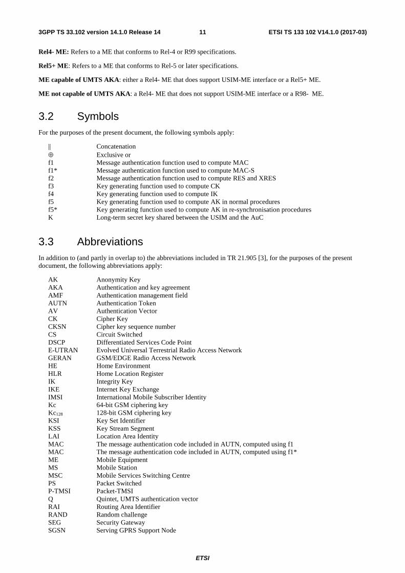
3.2 Symbols For the purposes of the present document, the following symbols apply:
|| Concatenation ⊕ Exclusive or f1 Message authentication function used to compute MAC f1* Message authentication function used to compute MAC-S f2 Message authentication function used to compute RES and XRES f3 Key generating function used to compute CK f4 Key generating function used to compute IK f5 Key generating function used to compute AK in normal procedures f5* Key generating function used to compute AK in re-synchronisation procedures K Long-term secret key shared between the USIM and the AuC
3.3 Abbreviations In addition to (and partly in overlap to) the abbreviations included in TR 21.905 [3], for the purposes of the present document, the following abbreviations apply:
AK Anonymity Key AKA Authentication and key agreement AMF Authentication management field AUTN Authentication Token AV Authentication Vector CK Cipher Key CKSN Cipher key sequence number CS Circuit Switched DSCP Differentiated Services Code Point E-UTRAN Evolved Universal Terrestrial Radio Access Network GERAN GSM/EDGE Radio Access Network HE Home Environment HLR Home Location Register IK Integrity Key IKE Internet Key Exchange IMSI International Mobile Subscriber Identity Kc 64-bit GSM ciphering key Kc128 128-bit GSM ciphering key KSI Key Set Identifier KSS Key Stream Segment LAI Location Area Identity MAC The message authentication code included in AUTN, computed using f1 MAC The message authentication code included in AUTN, computed using f1* ME Mobile Equipment MS Mobile Station MSC Mobile Services Switching Centre PS Packet Switched P-TMSI Packet-TMSI Q Quintet, UMTS authentication vector RAI Routing Area Identifier RAND Random challenge SEG Security Gateway SGSN Serving GPRS Support Node
ETSI
ETSI TS 133 102 V14.1.0 (2017-03)123GPP TS 33.102 version 14.1.0 Release 14
SIM (GSM) Subscriber Identity Module SN Serving Network SQN Sequence number SQNHE Individual sequence number for each user maintained in the HLR/AuC SQNMS The highest sequence number the USIM has accepted SRVCC Single Radio Voice Call Continuity T Triplet, GSM authentication vector TMSI Temporary Mobile Subscriber Identity UEA UMTS Encryption Algorithm UIA UMTS Integrity Algorithm UICC UMTS IC Card USIM Universal Subscriber Identity Module UTRAN Universal Terrestrial Radio Access Network VLR Visitor Location Register XRES Expected Response
3.4 Conventions All data variables in this specification are presented with the most significant substring on the left hand side and the least significant substring on the right hand side. A substring may be a bit, byte or other arbitrary length bitstring. Where a variable is broken down into a number of substrings, the leftmost (most significant) substring is numbered 0, the next most significant is numbered 1, and so on through to the least significant.
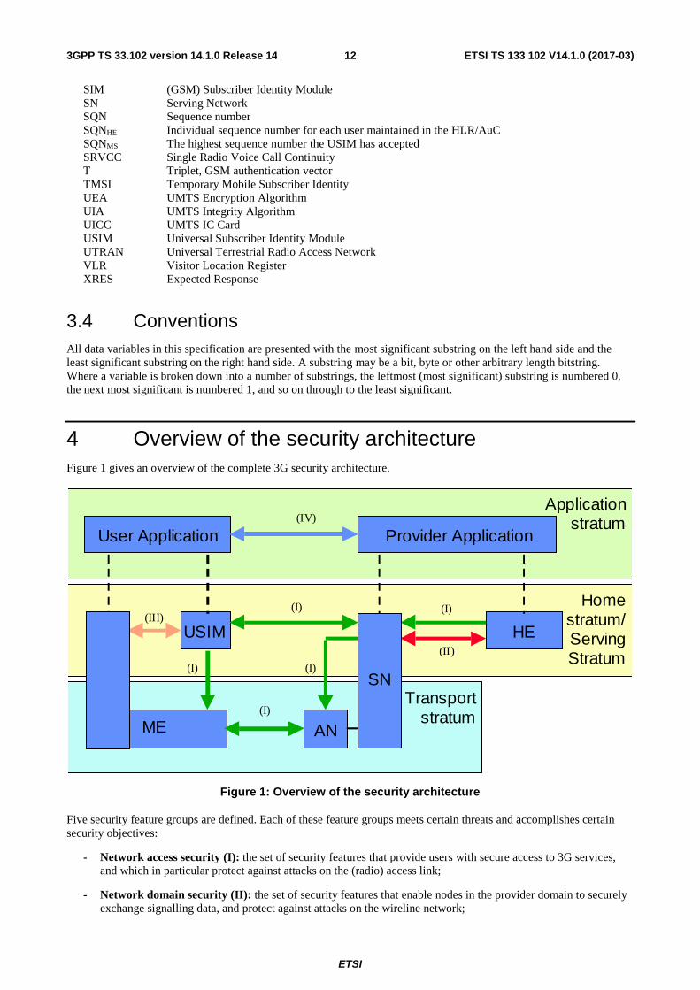
4 Overview of the security architecture Figure 1 gives an overview of the complete 3G security architecture.
Homestratum/ServingStratum
USIM HE
TransportstratumME
SN
AN
Applicationstratum
User Application Provider Application(IV)
(III)
(II)
(I)
(I)
(I)
(I)
(I)
Figure 1: Overview of the security architecture
Five security feature groups are defined. Each of these feature groups meets certain threats and accomplishes certain security objectives:
- Network access security (I): the set of security features that provide users with secure access to 3G services, and which in particular protect against attacks on the (radio) access link;
- Network domain security (II): the set of security features that enable nodes in the provider domain to securely exchange signalling data, and protect against attacks on the wireline network;
ETSI
ETSI TS 133 102 V14.1.0 (2017-03)133GPP TS 33.102 version 14.1.0 Release 14
- User domain security (III): the set of security features that secure access to mobile stations;
- Application domain security (IV): the set of security features that enable applications in the user and in the provider domain to securely exchange messages;
- Visibility and configurability of security (V): the set of features that enables the user to inform himself whether a security feature is in operation or not and whether the use and provision of services should depend on the security feature.
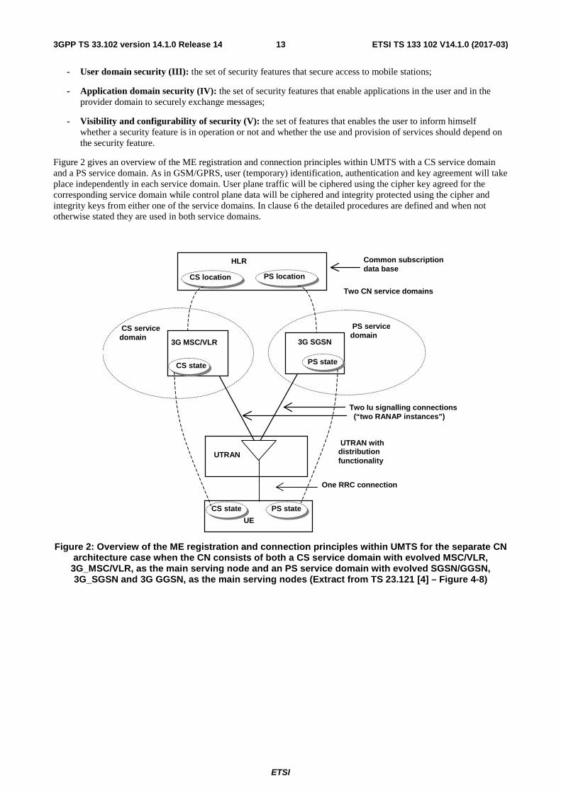
Figure 2 gives an overview of the ME registration and connection principles within UMTS with a CS service domain and a PS service domain. As in GSM/GPRS, user (temporary) identification, authentication and key agreement will take place independently in each service domain. User plane traffic will be ciphered using the cipher key agreed for the corresponding service domain while control plane data will be ciphered and integrity protected using the cipher and integrity keys from either one of the service domains. In clause 6 the detailed procedures are defined and when not otherwise stated they are used in both service domains.
Figure 2: Overview of the ME registration and connection principles within UMTS for the separate CN architecture case when the CN consists of both a CS service domain with evolved MSC/VLR, 3G_MSC/VLR, as the main serving node and an PS service domain with evolved SGSN/GGSN, 3G_SGSN and 3G GGSN, as the main serving nodes (Extract from TS 23.121 [4] – Figure 4-8)
Two Iu signalling connections (“two RANAP instances”)
UTRAN
3G SGSN
HLR
3G MSC/VLR
UE
CS servicedomain
Two CN service domains
One RRC connection
UTRAN withdistributionfunctionality
PS servicedomain
Common subscription data base
CS state PS state
PS state CS state
CS location PS location

ETSI
ETSI TS 133 102 V14.1.0 (2017-03)143GPP TS 33.102 version 14.1.0 Release 14
5 Security features
5.1 Network access security
5.1.1 User identity confidentiality
The following security features related to user identity confidentiality are provided:
- user identity confidentiality: the property that the permanent user identity (IMSI) of a user to whom a services is delivered cannot be eavesdropped on the radio access link;
- user location confidentiality: the property that the presence or the arrival of a user in a certain area cannot be determined by eavesdropping on the radio access link;
- user untraceability: the property that an intruder cannot deduce whether different services are delivered to the same user by eavesdropping on the radio access link.
To achieve these objectives, the user is normally identified by a temporary identity by which he is known by the visited serving network. To avoid user traceability, which may lead to the compromise of user identity confidentiality, the user should not be identified for a long period by means of the same temporary identity. To achieve these security features, in addition it is required that any signalling or user data that might reveal the user's identity is ciphered on the radio access link.
Clause 6.1 describes a mechanism that allows a user to be identified on the radio path by means of a temporary identity by which he is known in the visited serving network. This mechanism should normally be used to identify a user on the radio path in location update requests, service requests, detach requests, connection re-establishment requests, etc.
5.1.2 Entity authentication
The following security features related to entity authentication are provided:
- user authentication: the property that the serving network corroborates the user identity of the user;
- network authentication: the property that the user corroborates that he is connected to a serving network that is authorised by the user's HE to provide him services; this includes the guarantee that this authorisation is recent.
To achieve these objectives, it is assumed that entity authentication should occur at each connection set-up between the user and the network. Two mechanisms have been included: an authentication mechanism using an authentication vector delivered by the user's HE to the serving network, and a local authentication mechanism using the integrity key established between the user and serving network during the previous execution of the authentication and key establishment procedure.
Clause 6.3 describes an authentication and key establishment mechanism that achieves the security features listed above and in addition establishes a secret cipher key (see 5.1.3) and integrity key (see 5.1.4) between the user and the serving network. This mechanism should be invoked by the serving network after a first registration of a user in a serving network and after a service request, location update request, attach request, detach request or connection re-establishment request, when the maximum number of local authentications using the derived integrity key have been conducted.
Clause 6.5 describes the local authentication mechanism. The local authentication mechanism achieves the security features user authentication and network authentication and uses an integrity key established between user and serving network during the previous execution of the authentication and key establishment procedure. This mechanism should be invoked by the serving network after a service request, location update request, attach request, detach request or connection re-establishment request, provided that the maximum number of local authentications using the same derived integrity key has not been reached yet.
5.1.3 Confidentiality
The following security features are provided with respect to confidentiality of data on the network access link:
ETSI
ETSI TS 133 102 V14.1.0 (2017-03)153GPP TS 33.102 version 14.1.0 Release 14
- cipher algorithm agreement: the property that the MS and the SN can securely negotiate the algorithm that they shall use subsequently;
- cipher key agreement: the property that the MS and the SN agree on a cipher key that they may use subse-quently;
- confidentiality of user data: the property that user data cannot be overheard on the radio access interface;
- confidentiality of signalling data: the property that signalling data cannot be overheard on the radio access interface;
Cipher key agreement is realised in the course of the execution of the mechanism for authentication and key agreement (see 6.3). Cipher algorithm agreement is realised by means of a mechanism for security mode negotiation between the user and the network (see 6.4.5). This mechanism also enables the selected ciphering algorithm and the agreed cipher key to be applied in the way described in 6.6.
5.1.4 Data integrity
The following security features are provided with respect to integrity of data on the network access link:
- integrity algorithm agreement: the property that the MS and the SN can securely negotiate the integrity algorithm that they shall use subsequently;
- integrity key agreement: the property that the MS and the SN agree on an integrity key that they may use subsequently;
- data integrity and origin authentication of signalling data: the property that the receiving entity (MS or SN) is able to verify that signalling data has not been modified in an unauthorised way since it was sent by the sending entity (SN or MS) and that the data origin of the signalling data received is indeed the one claimed;
Integrity key agreement is realised in the course of the execution of the mechanism for authentication and key agreement (see 6.3). Integrity algorithm agreement is realised by means of a mechanism for security mode negotiation between the user and the network (see 6.4.5). This mechanism also enables the selected integrity algorithm and the agreed integrity key to be applied in the way described in 6.5.
5.1.5 Mobile equipment identification
The SN may request the MS to send it the IMEI or IMEISV of the terminal. The IMEI should be securely stored in the terminal. However, the presentation of this identity to the network is not a security feature and the transmission of the IMEI or IMEISV may be unprotected. Although it is not a security feature, it should not be deleted from UMTS however, as it is useful for other purposes.
5.2 Network domain security
5.2.1 Void
5.2.2 Void
5.2.3 Void

ETSI
ETSI TS 133 102 V14.1.0 (2017-03)163GPP TS 33.102 version 14.1.0 Release 14
5.2.4 Fraud information gathering system
NOTE: Some feature will be provided which will allow fraud information to be exchanged between 3GMS providers according to time constraints that yet have to be defined.
5.3 User domain security
5.3.1 User-to-USIM authentication
This feature provides the property that access to the USIM is restricted until the USIM has authenticated the user. Thereby, it is ensured that access to the USIM can be restricted to an authorised user or to a number of authorised users. To accomplish this feature, user and USIM must share a secret (e.g. a PIN) that is stored securely in the USIM. The user gets access to the USIM only if he/she proves knowledge of the secret.
This security feature is implemented by means of the mechanism described in TS 31.101 [5].
5.3.2 USIM-Terminal Link
This feature ensures that access to a terminal or other user equipment can be restricted to an authorised USIM. To this end, the USIM and the terminal must share a secret that is stored securely in the USIM and the terminal. If a USIM fails to prove its knowledge of the secret, it will be denied access to the terminal.
This security feature is implemented by means of the mechanism described in TS 22.022 [6].
5.4 Application security
5.4.1 Secure messaging between the USIM and the network
USIM Application Toolkit, as specified in TS 31.111 [15], provides the capability for operators or third party providers to create applications which are resident on the USIM (similar to SIM Application Toolkit in GSM). There exists a need to secure messages which are transferred over the network to applications on the USIM, with the level of security chosen by the network operator or the application provider.
Security features for USIM Application Toolkit are implemented by means of the mechanisms described in TS 23.048 [7]. These mechanisms address the security requirements identified in TS 22.048 [16].
5.4.2 Void
5.4.3 Void
5.4.4 Void
ETSI
ETSI TS 133 102 V14.1.0 (2017-03)173GPP TS 33.102 version 14.1.0 Release 14
5.5 Security visibility and configurability
5.5.1 Visibility
Although in general the security features should be transparent to the user, for certain events and according to the user's concern, greater user visibility of the operation of security features should be provided. This yields to a number of features that inform the user of security-related events, such as:
- indication of access network encryption: the property that the user is informed whether the confidentiality of user data is protected on the radio access link, in particular when non-ciphered calls are set-up;
- indication of the level of security: the property that the user is informed on the level of security that is provided by the visited network, in particular when a user is handed over or roams into a network with lower security level (3G � 2G).
The ciphering indicator feature is specified in 3GPP TS 22.101 [ 21].
5.5.2 Configurability
Configurability is the property that that the user can configure whether the use or the provision of a service should depend on whether a security feature is in operation. A service can only be used if all security features, which are relevant to that service and which are required by the configurations of the user, are in operation. The following configurability features are suggested:
- Enabling/disabling user-USIM authentication: the user should be able to control the operation of user-USIM authentication, e.g., for some events, services or use.
- Accepting/rejecting incoming non-ciphered calls: the user should be able to control whether the user accepts or rejects incoming non-ciphered calls;
- Setting up or not setting-up non-ciphered calls: the user should be able to control whether the user sets up connections when ciphering is not enabled by the network;
- Accepting/rejecting the use of certain ciphering algorithms: the user should be able to control which ciphering algorithms are acceptable for use.
6 Network access security mechanisms
6.1 Identification by temporary identities
6.1.1 General
This mechanism allows the identification of a user on the radio access link by means of a temporary mobile subscriber identity (TMSI/P-TMSI). A TMSI /P-TMSI has local significance only in the location area or routing area in which the user is registered. Outside that area it should be a accompanied by an appropriate Location Area Identification (LAI) or Routing Area Identification (RAI) in order to avoid ambiguities. The association between the permanent and temporary user identities is kept by the Visited Location Register (VLR/SGSN) in which the user is registered.
The TMSI/P-TMSI, when available, is normally used to identify the user on the radio access path, for instance in paging requests, location update requests, attach requests, service requests, connection re-establishment requests and detach requests.
The procedures and mechanisms are described in 3GPP TS 43.020 [8] and TS 23.060 [9]. The following sections contain a summary of this feature.
ETSI
ETSI TS 133 102 V14.1.0 (2017-03)183GPP TS 33.102 version 14.1.0 Release 14
6.1.2 TMSI reallocation procedure
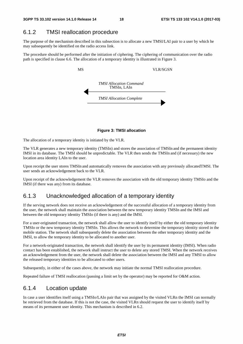
The purpose of the mechanism described in this subsection is to allocate a new TMSI/LAI pair to a user by which he may subsequently be identified on the radio access link.
The procedure should be performed after the initiation of ciphering. The ciphering of communication over the radio path is specified in clause 6.6. The allocation of a temporary identity is illustrated in Figure 3.
MS VLR/SGSN
TMSI Allocation Complete
TMSI Allocation Command TMSIn, LAIn
Figure 3: TMSI allocation
The allocation of a temporary identity is initiated by the VLR.
The VLR generates a new temporary identity (TMSIn) and stores the association of TMSIn and the permanent identity IMSI in its database. The TMSI should be unpredictable. The VLR then sends the TMSIn and (if necessary) the new location area identity LAIn to the user.
Upon receipt the user stores TMSIn and automatically removes the association with any previously allocatedTMSI. The user sends an acknowledgement back to the VLR.
Upon receipt of the acknowledgement the VLR removes the association with the old temporary identity TMSIo and the IMSI (if there was any) from its database.
6.1.3 Unacknowledged allocation of a temporary identity
If the serving network does not receive an acknowledgement of the successful allocation of a temporary identity from the user, the network shall maintain the association between the new temporary identity TMSIn and the IMSI and between the old temporary identity TMSIo (if there is any) and the IMSI.
For a user-originated transaction, the network shall allow the user to identify itself by either the old temporary identity TMSIo or the new temporary identity TMSIn. This allows the network to determine the temporary identity stored in the mobile station. The network shall subsequently delete the association between the other temporary identity and the IMSI, to allow the temporary identity to be allocated to another user.
For a network-originated transaction, the network shall identify the user by its permanent identity (IMSI). When radio contact has been established, the network shall instruct the user to delete any stored TMSI. When the network receives an acknowledgement from the user, the network shall delete the association between the IMSI and any TMSI to allow the released temporary identities to be allocated to other users.
Subsequently, in either of the cases above, the network may initiate the normal TMSI reallocation procedure.
Repeated failure of TMSI reallocation (passing a limit set by the operator) may be reported for O&M action.
6.1.4 Location update
In case a user identifies itself using a TMSIo/LAIo pair that was assigned by the visited VLRn the IMSI can normally be retrieved from the database. If this is not the case, the visited VLRn should request the user to identify itself by means of its permanent user identity. This mechanism is described in 6.2.
ETSI
ETSI TS 133 102 V14.1.0 (2017-03)193GPP TS 33.102 version 14.1.0 Release 14
In case a user identifies itself using a TMSIo/LAIo pair that was not assigned by the visited VLRn and the visited VLRn and the previously visited VLRo exchange authentication data, the visited VLRn should request the previously visited VLRo to send the permanent user identity. This mechanism is described in 6.3.4, it is integrated in the mechanism for distribution of authentication data between VLRs. If the previously visited VLRo cannot be contacted or cannot retrieve the user identity, the visited VLRn should request the user to identify itself by means of its permanent user identity. This mechanism is described in 6.2.
6.2 Identification by a permanent identity The mechanism described in here allows the identification of a user on the radio path by means of the permanent subscriber identity (IMSI).
The mechanism should be invoked by the serving network whenever the user cannot be identified by means of a temporary identity. In particular, it should be used when the user registers for the first time in a serving network, or when the serving network cannot retrieve the IMSI from the TMSI by which the user identifies itself on the radio path.
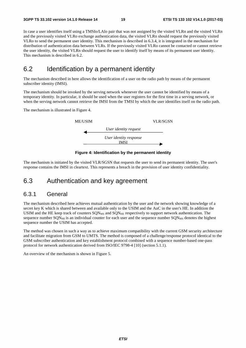
The mechanism is illustrated in Figure 4.
Figure 4: Identification by the permanent identity
The mechanism is initiated by the visited VLR/SGSN that requests the user to send its permanent identity. The user's response contains the IMSI in cleartext. This represents a breach in the provision of user identity confidentiality.
6.3 Authentication and key agreement
6.3.1 General
The mechanism described here achieves mutual authentication by the user and the network showing knowledge of a secret key K which is shared between and available only to the USIM and the AuC in the user's HE. In addition the USIM and the HE keep track of counters SQNMS and SQNHE respectively to support network authentication. The sequence number SQNHE is an individual counter for each user and the sequence number SQNMS denotes the highest sequence number the USIM has accepted.
The method was chosen in such a way as to achieve maximum compatibility with the current GSM security architecture and facilitate migration from GSM to UMTS. The method is composed of a challenge/response protocol identical to the GSM subscriber authentication and key establishment protocol combined with a sequence number-based one-pass protocol for network authentication derived from ISO/IEC 9798-4 [10] (section 5.1.1).
An overview of the mechanism is shown in Figure 5.
ME/USIM VLR/SGSN
User identity responseIMSI
User identity request

ETSI
ETSI TS 133 102 V14.1.0 (2017-03)203GPP TS 33.102 version 14.1.0 Release 14
Figure 5: Authentication and key agreement
Upon receipt of a request from the VLR/SGSN, the HE/AuC sends an ordered array of n authentication vectors (the equivalent of a GSM "triplet") to the VLR/SGSN. The authentication vectors are ordered based on sequence number. Each authentication vector consists of the following components: a random number RAND, an expected response XRES, a cipher key CK, an integrity key IK and an authentication token AUTN. Each authentication vector is good for one authentication and key agreement between the VLR/SGSN and the USIM.
When the VLR/SGSN initiates an authentication and key agreement, it selects the next authentication vector from the ordered array and sends the parameters RAND and AUTN to the user. Authentication vectors in a particular node are used on a first-in / first-out basis. The USIM checks whether AUTN can be accepted and, if so, produces a response RES which is sent back to the VLR/SGSN. The USIM also computes CK and IK. The VLR/SGSN compares the received RES with XRES. If they match the VLR/SGSN considers the authentication and key agreement exchange to be successfully completed. The established keys CK and IK will then be transferred by the USIM and the VLR/SGSN to the entities which perform ciphering and integrity functions.
VLR/SGSNs can offer secure service even when HE/AuC links are unavailable by allowing them to use previously derived cipher and integrity keys for a user so that a secure connection can still be set up without the need for an authentication and key agreement. Authentication is in that case based on a shared integrity key, by means of data integrity protection of signalling messages (see 6.4).
The authenticating parties shall be the AuC of the user's HE (HE/AuC) and the USIM in the user's mobile station. The mechanism consists of the following procedures:
MS VLR/SGSN HE/HLR
Generate authenticationvectors AV(1..n)
Store authentication vectors
Select authentication vector AV(i)
Authentication data request
Authentication data responseAV(1..n)
User authentication requestRAND(i) || AUTN(i)
User authentication responseRES(i)
Compare RES(i) and XRES(i)
Verify AUTN(i)Compute RES(i)
Compute CK(i) and IK(i) Select CK(i) and IK(i)
Authentication andkey establishment
Distribution ofauthenticationvectors from HEto SN
ETSI
ETSI TS 133 102 V14.1.0 (2017-03)213GPP TS 33.102 version 14.1.0 Release 14
A procedure to distribute authentication information from the HE/AuC to the VLR/SGSN. This procedure is described in 6.3.2. The VLR/SGSN is assumed to be trusted by the user's HE to handle authentication information securely. It is also assumed that the intra-system links between the VLR/SGSN to the HE/AuC are adequately secure. It is further assumed that the user trusts the HE.
A procedure to mutually authenticate and establish new cipher and integrity keys between the VLR/SGSN and the MS. This procedure is described in 6.3.3.
A procedure to distribute authentication data from a previously visited VLR to the newly visited VLR. This procedure is described in 6.3.4. It is also assumed that the links between VLR/SGSNs are adequately secure.
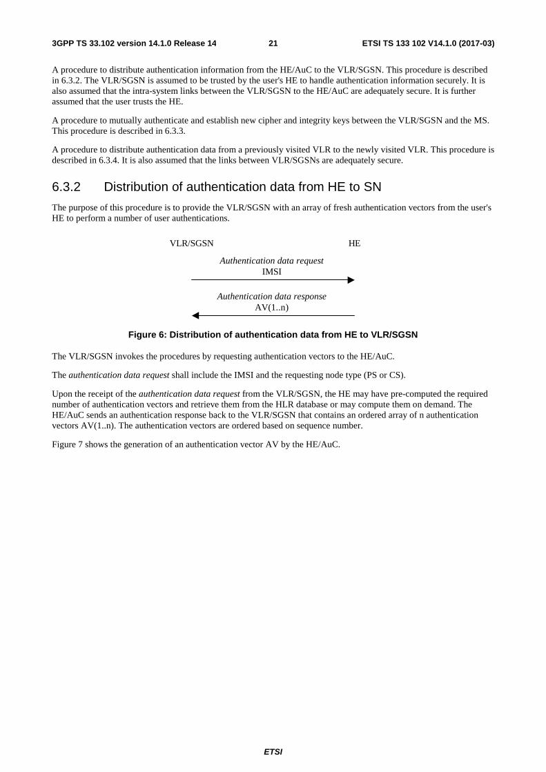
6.3.2 Distribution of authentication data from HE to SN
The purpose of this procedure is to provide the VLR/SGSN with an array of fresh authentication vectors from the user's HE to perform a number of user authentications.
VLR/SGSN HE
Authentication data requestIMSI
Authentication data responseAV(1..n)
Figure 6: Distribution of authentication data from HE to VLR/SGSN
The VLR/SGSN invokes the procedures by requesting authentication vectors to the HE/AuC.
The authentication data request shall include the IMSI and the requesting node type (PS or CS).
Upon the receipt of the authentication data request from the VLR/SGSN, the HE may have pre-computed the required number of authentication vectors and retrieve them from the HLR database or may compute them on demand. The HE/AuC sends an authentication response back to the VLR/SGSN that contains an ordered array of n authentication vectors AV(1..n). The authentication vectors are ordered based on sequence number.
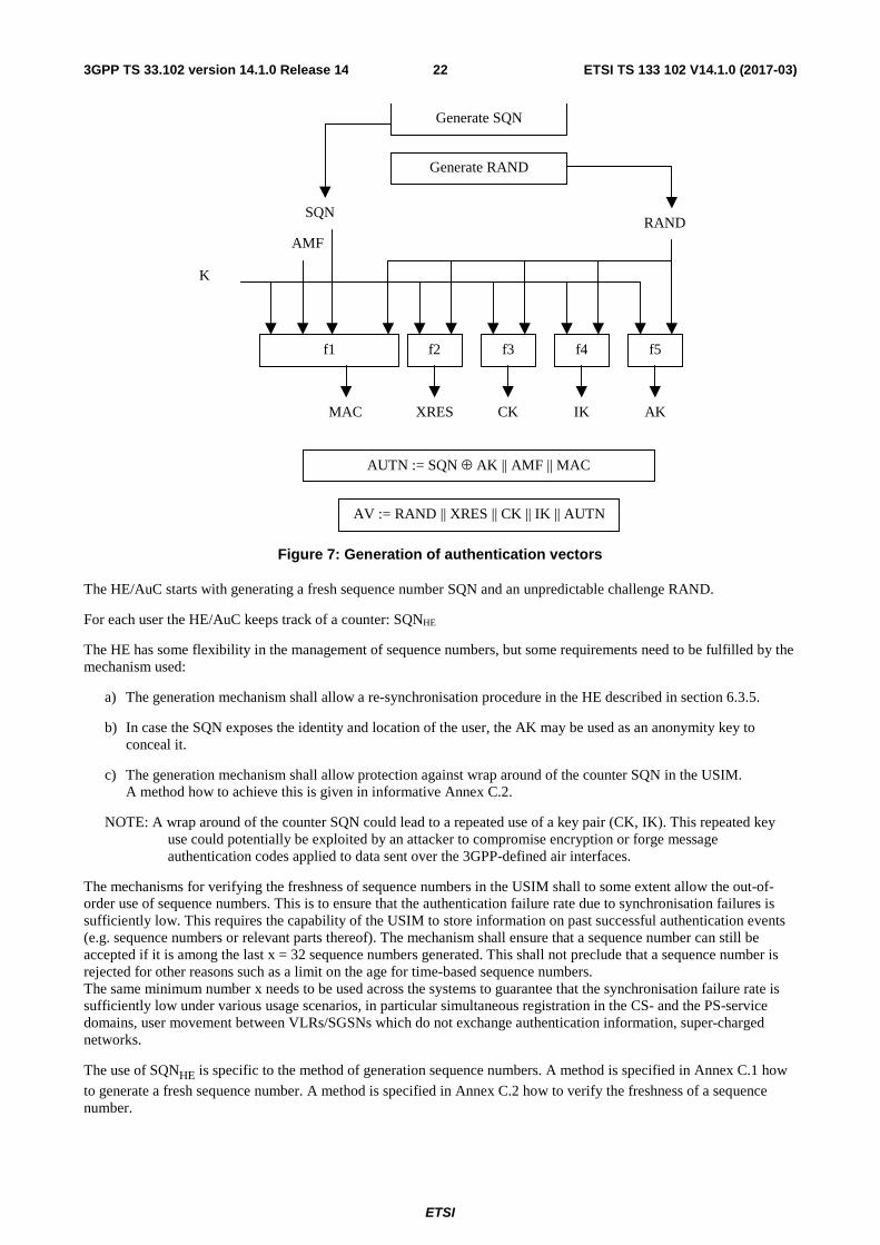
Figure 7 shows the generation of an authentication vector AV by the HE/AuC.
ETSI
ETSI TS 133 102 V14.1.0 (2017-03)223GPP TS 33.102 version 14.1.0 Release 14
K
SQNRAND
f1 f2 f3 f4 f5
MAC XRES CK IK AK
AUTN := SQN ⊕ AK || AMF || MAC
AV := RAND || XRES || CK || IK || AUTN
Generate SQN
Generate RAND
AMF
Figure 7: Generation of authentication vectors
The HE/AuC starts with generating a fresh sequence number SQN and an unpredictable challenge RAND.
For each user the HE/AuC keeps track of a counter: SQNHE
The HE has some flexibility in the management of sequence numbers, but some requirements need to be fulfilled by the mechanism used:
a) The generation mechanism shall allow a re-synchronisation procedure in the HE described in section 6.3.5.
b) In case the SQN exposes the identity and location of the user, the AK may be used as an anonymity key to conceal it.
c) The generation mechanism shall allow protection against wrap around of the counter SQN in the USIM. A method how to achieve this is given in informative Annex C.2.
NOTE: A wrap around of the counter SQN could lead to a repeated use of a key pair (CK, IK). This repeated key use could potentially be exploited by an attacker to compromise encryption or forge message authentication codes applied to data sent over the 3GPP-defined air interfaces.
The mechanisms for verifying the freshness of sequence numbers in the USIM shall to some extent allow the out-of-order use of sequence numbers. This is to ensure that the authentication failure rate due to synchronisation failures is sufficiently low. This requires the capability of the USIM to store information on past successful authentication events (e.g. sequence numbers or relevant parts thereof). The mechanism shall ensure that a sequence number can still be accepted if it is among the last x = 32 sequence numbers generated. This shall not preclude that a sequence number is rejected for other reasons such as a limit on the age for time-based sequence numbers. The same minimum number x needs to be used across the systems to guarantee that the synchronisation failure rate is sufficiently low under various usage scenarios, in particular simultaneous registration in the CS- and the PS-service domains, user movement between VLRs/SGSNs which do not exchange authentication information, super-charged networks.
The use of SQNHE is specific to the method of generation sequence numbers. A method is specified in Annex C.1 how
to generate a fresh sequence number. A method is specified in Annex C.2 how to verify the freshness of a sequence number.
ETSI
ETSI TS 133 102 V14.1.0 (2017-03)233GPP TS 33.102 version 14.1.0 Release 14
An authentication and key management field AMF is included in the authentication token of each authentication vector. Annex H defines the usage of the AMF. Example uses of the proprietary part of the AMF are included in Annex F.
Subsequently the following values are computed:
- a message authentication code MAC = f1K(SQN || RAND || AMF) where f1 is a message authentication function;
- an expected response XRES = f2K (RAND) where f2 is a (possibly truncated) message authentication function;
- a cipher key CK = f3K (RAND) where f3 is a key generating function;
- an integrity key IK = f4K (RAND) where f4 is a key generating function;
- an anonymity key AK = f5K (RAND) where f5 is a key generating function or f5 ≡ 0.
Finally the authentication token AUTN = SQN ⊕ AK || AMF || MAC is constructed.
Here, AK is an anonymity key used to conceal the sequence number as the latter may expose the identity and location of the user. The concealment of the sequence number is to protect against passive attacks only. If no concealment is needed then f5 ≡ 0 (AK = 0).
6.3.3 Authentication and key agreement
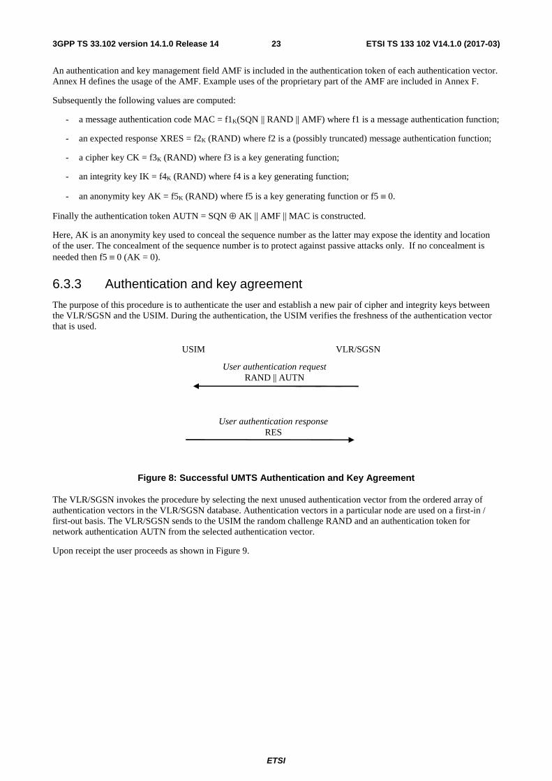
The purpose of this procedure is to authenticate the user and establish a new pair of cipher and integrity keys between the VLR/SGSN and the USIM. During the authentication, the USIM verifies the freshness of the authentication vector that is used.
USIM VLR/SGSN
User authentication request RAND || AUTN
User authentication response RES
Figure 8: Successful UMTS Authentication and Key Agreement
The VLR/SGSN invokes the procedure by selecting the next unused authentication vector from the ordered array of authentication vectors in the VLR/SGSN database. Authentication vectors in a particular node are used on a first-in / first-out basis. The VLR/SGSN sends to the USIM the random challenge RAND and an authentication token for network authentication AUTN from the selected authentication vector.
Upon receipt the user proceeds as shown in Figure 9.
ETSI
ETSI TS 133 102 V14.1.0 (2017-03)243GPP TS 33.102 version 14.1.0 Release 14
K
SQN
RAND
f1 f2 f3 f4
f5
XMAC RES CK IK
AK
SQN ⊕ AK AMF MAC
AUTN
Verify MAC = XMAC
Verify that SQN is in the correct range
⊕
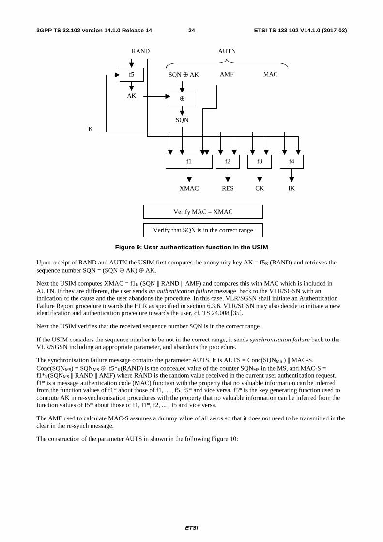
Figure 9: User authentication function in the USIM
Upon receipt of RAND and AUTN the USIM first computes the anonymity key AK = f5K (RAND) and retrieves the sequence number SQN = (SQN ⊕ AK) ⊕ AK.
Next the USIM computes XMAC = f1K (SQN || RAND || AMF) and compares this with MAC which is included in AUTN. If they are different, the user sends an authentication failure message back to the VLR/SGSN with an indication of the cause and the user abandons the procedure. In this case, VLR/SGSN shall initiate an Authentication Failure Report procedure towards the HLR as specified in section 6.3.6. VLR/SGSN may also decide to initiate a new identification and authentication procedure towards the user, cf. TS 24.008 [35].
Next the USIM verifies that the received sequence number SQN is in the correct range.
If the USIM considers the sequence number to be not in the correct range, it sends synchronisation failure back to the VLR/SGSN including an appropriate parameter, and abandons the procedure.
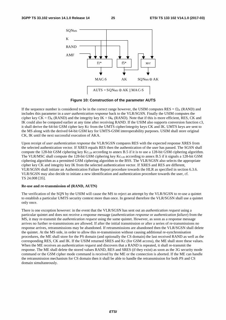
The synchronisation failure message contains the parameter AUTS. It is AUTS = Conc(SQNMS ) || MAC-S. Conc(SQNMS) = SQNMS ⊕ f5*K(RAND) is the concealed value of the counter SQNMS in the MS, and MAC-S = f1*K(SQNMS || RAND || AMF) where RAND is the random value received in the current user authentication request. f1* is a message authentication code (MAC) function with the property that no valuable information can be inferred from the function values of f1* about those of f1, ... , f5, f5* and vice versa. f5* is the key generating function used to compute AK in re-synchronisation procedures with the property that no valuable information can be inferred from the function values of f5* about those of f1, f1*, f2, ... , f5 and vice versa.
The AMF used to calculate MAC-S assumes a dummy value of all zeros so that it does not need to be transmitted in the clear in the re-synch message.
The construction of the parameter AUTS in shown in the following Figure 10:
ETSI
ETSI TS 133 102 V14.1.0 (2017-03)253GPP TS 33.102 version 14.1.0 Release 14
RAND
SQNMS
K
AUTS = SQNMS ⊕ AK || MA C-S
AMF
f1* f5*
MAC-S AK SQNMS ⊕ AK
xor
Figure 10: Construction of the parameter AUTS
If the sequence number is considered to be in the correct range however, the USIM computes RES = f2K (RAND) and includes this parameter in a user authentication response back to the VLR/SGSN. Finally the USIM computes the cipher key CK = f3K (RAND) and the integrity key IK = f4K (RAND). Note that if this is more efficient, RES, CK and IK could also be computed earlier at any time after receiving RAND. If the USIM also supports conversion function c3, it shall derive the 64-bit GSM cipher key Kc from the UMTS cipher/integrity keys CK and IK. UMTS keys are sent to the MS along with the derived 64-bit GSM key for UMTS-GSM interoperability purposes. USIM shall store original CK, IK until the next successful execution of AKA.
Upon receipt of user authentication response the VLR/SGSN compares RES with the expected response XRES from the selected authentication vector. If XRES equals RES then the authentication of the user has passed. The SGSN shall compute the 128-bit GSM ciphering key Kc128 according to annex B.5 if it is to use a 128-bit GSM ciphering algorithm. The VLR/MSC shall compute the 128-bit GSM ciphering key Kc128 according to annex B.5 if it signals a 128-bit GSM ciphering algorithm as a permitted GSM ciphering algorithm to the BSS. The VLR/SGSN also selects the appropriate cipher key CK and integrity key IK from the selected authentication vector. If XRES and RES are different, VLR/SGSN shall initiate an Authentication Failure Report procedure towards the HLR as specified in section 6.3.6. VLR/SGSN may also decide to initiate a new identification and authentication procedure towards the user, cf. TS 24.008 [35].
Re-use and re-transmission of (RAND, AUTN)
The verification of the SQN by the USIM will cause the MS to reject an attempt by the VLR/SGSN to re-use a quintet to establish a particular UMTS security context more than once. In general therefore the VLR/SGSN shall use a quintet only once.
There is one exception however: in the event that the VLR/SGSN has sent out an authentication request using a particular quintet and does not receive a response message (authentication response or authentication failure) from the MS, it may re-transmit the authentication request using the same quintet. However, as soon as a response message arrives no further re-transmissions are allowed. If after the initial transmission or after a series of re-transmissions no response arrives, retransmissions may be abandoned. If retransmissions are abandoned then the VLR/SGSN shall delete the quintet. At the MS side, in order to allow this re-transmission without causing additional re-synchronisation procedures, the ME shall store for the PS domain (and optionally the CS domain) the last received RAND as well as the corresponding RES, CK and IK. If the USIM returned SRES and Kc (for GSM access), the ME shall store these values. When the ME receives an authentication request and discovers that a RAND is repeated, it shall re-transmit the response. The ME shall delete the stored values RAND, RES and SRES (if they exist) as soon as the 3G security mode command or the GSM cipher mode command is received by the ME or the connection is aborted. If the ME can handle the retransmission mechanism for CS domain then it shall be able to handle the retransmission for both PS and CS domain simultaneously.
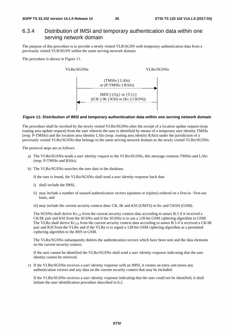
ETSI
ETSI TS 133 102 V14.1.0 (2017-03)263GPP TS 33.102 version 14.1.0 Release 14
6.3.4 Distribution of IMSI and temporary authentication data within one serving network domain
The purpose of this procedure is to provide a newly visited VLR/SGSN with temporary authentication data from a previously visited VLR/SGSN within the same serving network domain.
The procedure is shown in Figure 11.
Figure 11: Distribution of IMSI and temporary authentication data within one serving network domain
The procedure shall be invoked by the newly visited VLRn/SGSNn after the receipt of a location update request (resp. routing area update request) from the user wherein the user is identified by means of a temporary user identity TMSIo (resp. P-TMSIo) and the location area identity LAIo (resp. routing area identity RAIo) under the jurisdiction of a previously visited VLRo/SGSNo that belongs to the same serving network domain as the newly visited VLRn/SGSNn.
The protocol steps are as follows:
a) The VLRn/SGSNn sends a user identity request to the VLRo/SGSNo, this message contains TMSIo and LAIo (resp. P-TMSIo and RAIo).
b) The VLRo/SGSNo searches the user data in the database.
If the user is found, the VLRo/SGSNo shall send a user identity response back that:
i) shall include the IMSI,
ii) may include a number of unused authentication vectors (quintets or triplets) ordered on a first-in / first-out basis, and
iii) may include the current security context data: CK, IK and KSI (UMTS) or Kc and CKSN (GSM).
The SGSNn shall derive Kc128 from the current security context data according to annex B.5 if it received a CK/IK pair and KSI from the SGSNo and if the SGSNn is to use a 128-bit GSM ciphering algorithm in GSM. The VLRn shall derive Kc128 from the current security context data according to annex B.5 if it received a CK/IK pair and KSI from the VLRo and if the VLRn is to signal a 128-bit GSM ciphering algorithm as a permitted ciphering algorithm to the BSS in GSM.
The VLRo/SGSNo subsequently deletes the authentication vectors which have been sent and the data elements on the current security context.
If the user cannot be identified the VLRo/SGSNo shall send a user identity response indicating that the user identity cannot be retrieved.
c) If the VLRn/SGSNn receives a user identity response with an IMSI, it creates an entry and stores any authentication vectors and any data on the current security context that may be included.
If the VLRn/SGSNn receives a user identity response indicating that the user could not be identified, it shall initiate the user identification procedure described in 6.2.
VLRn/SGSNn VLRo/SGSNo
(TMSIo || LAIo)or (P-TMSIo || RAIo)
IMSI || ({Qi} or {Ti}) ||((CK || IK || KSI) or (Kc || CKSN))

ETSI
ETSI TS 133 102 V14.1.0 (2017-03)273GPP TS 33.102 version 14.1.0 Release 14
6.3.5 Re-synchronisation procedure
A VLR/SGSN may send two types of authentication data requests to the HE/AuC, the (regular) one described in subsection 6.3.2 and one used in case of synchronisation failures, described in this subsection.
Upon receiving a synchronisation failure message from the user, the VLR/SGSN sends an authentication data request with a "synchronisation failure indication" to the HE/AuC, together with the parameters:
- RAND sent to the MS in the preceding user authentication request, and
- AUTS received by the VLR/SGSN in the response to that request, as described in subsection 6.3.3.
An VLR/SGSN will not react to unsolicited "synchronisation failure indication" messages from the MS.
The VLR/SGSN does not send new user authentication requests to the user before having received the response to its authentication data request from the HE/AuC (or before it is timed out).
When the HE/AuC receives an authentication data request with a "synchronisation failure indication" it acts as follows:
1. The HE/AuC retrieves SQNMS from Conc(SQNMS) by computing Conc(SQNMS) ⊕ f5*K(RAND).
2. The HE/AuC checks if SQNHE is in the correct range, i.e. if the next sequence number generated SQNHE using would be accepted by the USIM.
3. If SQNHE is in the correct range then the HE/AuC continues with step (6), otherwise it continues with step (4).
4. The HE/AuC verifies AUTS (cf. subsection 6.3.3).
5. If the verification is successful the HE/AuC resets the value of the counter SQNHE to SQNMS.
6. The HE/AuC sends an authentication data response with a new batch of authentication vectors to the VLR/SGSN. If the counter SQNHE was not reset then these authentication vectors can be taken from storage, otherwise they are newly generated after resetting SQNHE. In order to reduce the real-time computation burden on the HE/AuC, the HE/AuC may also send only a single authentication vector in the latter case.
Whenever the VLR/SGSN receives a new batch of authentication vectors from the HE/AuC in an authentication data response to an authentication data request with synchronisation failure indication it deletes the old ones for that user in the VLR/SGSN.
The user may now be authenticated based on a new authentication vector from the HE/AuC. Figure 12 shows how re-synchronisation is achieved by combining a user authentication request answered by a synchronisation failure message (as described in section 6.3.3) with an authentication data request with synchronisation failure indication answered by an authentication data response (as described in this section).
Figure 12: Resynchronisation mechanism
UE/USIM VLR/SGSN HLR/AuC
RAND, AUTN
AUTS
RAND, AUTS
{Qi}
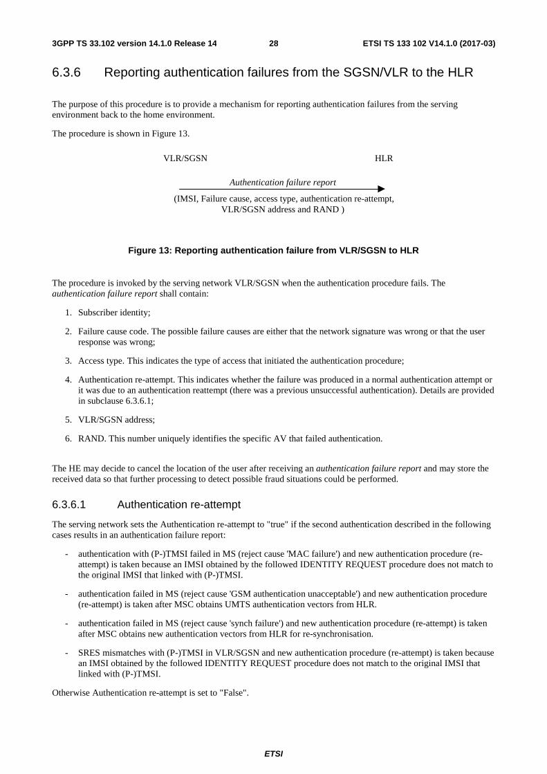
ETSI
ETSI TS 133 102 V14.1.0 (2017-03)283GPP TS 33.102 version 14.1.0 Release 14
6.3.6 Reporting authentication failures from the SGSN/VLR to the HLR
The purpose of this procedure is to provide a mechanism for reporting authentication failures from the serving environment back to the home environment.
The procedure is shown in Figure 13.
Figure 13: Reporting authentication failure from VLR/SGSN to HLR
The procedure is invoked by the serving network VLR/SGSN when the authentication procedure fails. The authentication failure report shall contain:
1. Subscriber identity;
2. Failure cause code. The possible failure causes are either that the network signature was wrong or that the user response was wrong;
3. Access type. This indicates the type of access that initiated the authentication procedure;
4. Authentication re-attempt. This indicates whether the failure was produced in a normal authentication attempt or it was due to an authentication reattempt (there was a previous unsuccessful authentication). Details are provided in subclause 6.3.6.1;
5. VLR/SGSN address;
6. RAND. This number uniquely identifies the specific AV that failed authentication.
The HE may decide to cancel the location of the user after receiving an authentication failure report and may store the received data so that further processing to detect possible fraud situations could be performed.
6.3.6.1 Authentication re-attempt
The serving network sets the Authentication re-attempt to "true" if the second authentication described in the following cases results in an authentication failure report:
- authentication with (P-)TMSI failed in MS (reject cause 'MAC failure') and new authentication procedure (re-attempt) is taken because an IMSI obtained by the followed IDENTITY REQUEST procedure does not match to the original IMSI that linked with (P-)TMSI.
- authentication failed in MS (reject cause 'GSM authentication unacceptable') and new authentication procedure (re-attempt) is taken after MSC obtains UMTS authentication vectors from HLR.
- authentication failed in MS (reject cause 'synch failure') and new authentication procedure (re-attempt) is taken after MSC obtains new authentication vectors from HLR for re-synchronisation.
- SRES mismatches with (P-)TMSI in VLR/SGSN and new authentication procedure (re-attempt) is taken because an IMSI obtained by the followed IDENTITY REQUEST procedure does not match to the original IMSI that linked with (P-)TMSI.
Otherwise Authentication re-attempt is set to "False".
VLR/SGSN HLR
Authentication failure report
(IMSI, Failure cause, access type, authentication re-attempt, VLR/SGSN address and RAND )
ETSI
ETSI TS 133 102 V14.1.0 (2017-03)293GPP TS 33.102 version 14.1.0 Release 14
6.3.7 Length of authentication parameters
The authentication key (K) shall have a length of 128 bits or 256 bits.
NOTE: Examples of algorithm set for 3GPP authentication and key agreement functions allow either an authentication key K with only a length of 128 bits, or an authentication key K with a length of 128 bits or 256 bits. Depending on the chosen algorithm set, the operator may have the choice of the length of the authentication key K (128 bits or 256 bits).
The random challenge (RAND) shall have a length of 128 bits.
Sequence numbers (SQN) shall have a length of 48 bits.
The anonymity key (AK) shall have a length of 48 bits.
The authentication management field (AMF) shall have a length of 16 bits.
The message authentication codes MAC in AUTN and MAC-S in AUTS shall have a length of 64 bits.
The cipher key (CK) shall have a length of 128 bits.
The integrity key (IK) shall have a length of 128 bits.
The authentication response (RES) shall have a variable length of 4-16 octets.
6.4 Local authentication and connection establishment Local authentication is obtained by integrity protection functionality.
6.4.1 Cipher key and integrity key setting
Authentication and key setting are triggered by the authentication procedure and described in 6.3. Authentication and key setting may be initiated by the network as often as the network operator wishes. Key setting can occur as soon as the identity of the mobile subscriber (i.e. P-TMSI, TMSI or IMSI) is known by the VLR/SGSN. The CK and IK are stored in the VLR/SGSN and transferred to the RNC when needed. The CK and IK for the CS domain are stored on the USIM and updated at the next authentication from this domain as specified in subclause 6.8.1.5. The CK and IK for the PS domain are stored on the USIM and updated at the next authentication from this domain as specified in subclause 6.8.1.5.
If an authentication procedure is performed during a connection (PS or CS mode), the new cipher key CK and integrity key IK shall be taken in use in both the RNC and the ME as part of the security mode set-up procedure (see 6.4.5) that follows the authentication procedure.
6.4.2 Ciphering and integrity mode negotiation
When an MS wishes to establish a connection with the network, the MS shall indicate to the network in the MS/USIM Classmark which cipher and integrity algorithms the MS supports. This information itself must be integrity protected. As it is the case that the RNC does not have the integrity key IK when receiving the MS/USIM Classmark this information must be stored in the RNC. The data integrity of the classmark is performed, during the security mode set-up procedure by use of the most recently generated IK (see section 6.4.5).
The network shall compare its integrity protection capabilities and preferences, and any special requirements of the subscription of the MS, with those indicated by the MS and act according to the following rules:
1) If the MS and the network have no versions of the UIA algorithm in common, then the connection shall be released.
2) If the MS and the network have at least one version of the UIA algorithm in common, then the network shall select one of the mutually acceptable versions of the UIA algorithm for use on that connection.
ETSI
ETSI TS 133 102 V14.1.0 (2017-03)303GPP TS 33.102 version 14.1.0 Release 14
The network shall compare its ciphering capabilities and preferences, and any special requirements of the subscription of the MS, with those indicated by the MS and act according to the following rules:
1) If the MS and the network have no versions of the UEA algorithm in common and the network is not prepared to use an unciphered connection, then the connection shall be released.
2) If the MS and the network have no versions of the UEA algorithm in common and the user (respectively the user's HE) and the network are willing to use an unciphered connection, then an unciphered connection shall be used.
3) If the MS and the network have at least one version of the UEA algorithm in common, then the network shall select one of the mutually acceptable versions of the UEA algorithm for use on that connection.
Because of the separate mobility management for CS and PS services, one CN domain may, independent of the other CN, establish a connection to one and the same MS. Change of ciphering and integrity mode (algorithms) at establishment of a second MS to CN connection shall not be permitted. The preferences and special requirements for the ciphering and integrity mode setting shall be common for both domains. (e.g. the order of preference of the algorithms).
6.4.3 Cipher key and integrity key lifetime
Authentication and key agreement, which generates cipher/integrity keys, is not mandatory at call set-up, and there is therefore the possibility of unlimited and malicious re-use of compromised keys. A mechanism is needed to ensure that a particular cipher/integrity key set is not used for an unlimited period of time, to avoid attacks using compromised keys. The UE shall therefore contain a mechanism to limit the amount of data that is protected by an access link key set. For this purpose, a value called THRESHOLD is set by the operator, stored in the USIM and read out by the ME upon power on. Each time an RRC connection is released the values STARTCS and STARTPS of the bearers that were protected in that RRC connection are compared with THRESHOLD. If STARTCS and/or STARTPS are greater than or equal to THRESHOLD, the ME sets the START value in the ME for the corresponding core network domain(s) to zero, deletes the cipher key and the integrity key stored on the USIM and the ME and sets the KSI to invalid (refer to section 6.4.4). Otherwise, the STARTCS and STARTPS are stored in the ME.
The ME shall write back the values of STARTCS and/or STARTPS to the USIM only when the UE is about to power off in a controlled manner and there are valid UTRAN keys for that domain.
When the UE has powered on and before attempting to connect to any network, the ME reads the START values from the USIM and stores them in the volatile memory of ME. If STARTCS and/or STARTPS read from the USIM are greater than or equal to THRESHOLD or the KSI on the USIM is invalid, the ME sets the START value in the ME for the corresponding core network domain(s) to zero. The ME then marks the START values in the USIM as invalid by setting STARTCS and STARTPS to THRESHOLD. In addition for the former case, the ME deletes the cipher key and the integrity key stored on the USIM and sets the KSI to invalid (refer to section 6.4.4).
When an RRC connection is established the ME uses the START values from the volatile memory of the ME. The ME shall trigger the generation of a new access link key set (a cipher key and an integrity key) for a core network domain if either the START value for that domain in the ME is greater than or equal to THRESHOLD or if there are no valid keys in the ME nor in the USIM for that domain. In addition for the former case, the ME deletes the cipher key and the integrity key stored on the USIM, sets the KSI to invalid (refer to section 6.4.4) and sets the corresponding START value(s) in the ME to zero.
This mechanism will ensure that a cipher/integrity key set cannot be reused beyond the limit set by the operator.
When the user is attached to a UTRAN, a R99+ ME with a SIM inserted shall use a default value for maximum value of STARTCS or STARTPS as described in section 6.8.2.4. This maximum value of STARTCS or STARTPS corresponds to THRESHOLD as described in the present clause.
6.4.4 Cipher key and integrity key identification
The key set identifier (KSI) is a number which is associated with the cipher and integrity keys derived during authentication. The key set identifier is allocated by the network and sent with the authentication request message to the mobile station where it is stored together with the calculated cipher key CK and integrity key IK. KSI in UMTS corresponds to CKSN in GSM. The USIM stores one KSI/CKSN for the PS domain key set and one KSI/CKSN for the CS domain key set.

ETSI
ETSI TS 133 102 V14.1.0 (2017-03)313GPP TS 33.102 version 14.1.0 Release 14
The purpose of the key set identifier is to make it possible for the network to identify the cipher key CK and integrity key IK which are stored in the mobile station without invoking the authentication procedure. This is used to allow re-use of the cipher key CK and integrity key IK during subsequent connection set-ups.
KSI and CKSN have the same format. The key set identifier is three bits. Seven values are used to identify the key set. A value of '111' is used by the mobile station to indicate that a valid key is not available for use. At deletion of the cipher key and integrity key, the KSI is set to '111'. The value '111' in the other direction from network to mobile station is reserved.
6.4.5 Security mode set-up procedure
This section describes one common procedure for both ciphering and integrity protection set-up. It is mandatory to start integrity protection of signalling messages by use of this procedure at each new signalling connection establishment between MS and VLR/SGSN. The five exceptions when it is not mandatory to start integrity protection are:
- If the only purpose with the signalling connection establishment and the only result is periodic location registration, i.e. no change of any registration information.
- If there is no MS-VLR/SGSNsignalling after the initial L3 signalling message sent from MS to VLR/SGSN, i.e. in the case of deactivation indication sent from the MS followed by connection release.
- If the only MS-VLR/SGSN signalling after the initial L3 signalling message sent from MS to VLR/SGSN, and possible user identity request and authentication (see below), is a reject signalling message followed by a connection release. However, it shall be mandatory for the VLR/SGSN to start integrity protection before sending a reject signalling message that causes the CSG list on the UE to be modified.
- If the call is an emergency call teleservice as defined in TS 22.003, see section 6.4.9.2 below.
- If the PS connection establishment is for an emergency session, see clause 6.4.9.2 below.
When the integrity protection shall be started, the only procedures between MS and VLR/SGSN that are allowed after the initial connection request (i.e. the initial Layer 3 message sent to VLR/SGSN) and before the security mode set-up procedure are the following:
- Identification by a permanent identity (i.e. request for IMSI, IMEI or IMEISV), and
- Authentication and key agreement.
The message sequence flow below describes the information transfer at initial connection establishment, possible authentication and start of integrity protection and possible ciphering.
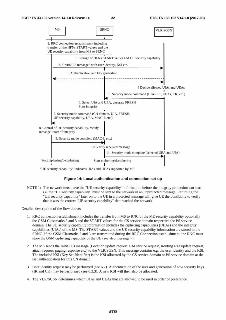
ETSI
ETSI TS 133 102 V14.1.0 (2017-03)323GPP TS 33.102 version 14.1.0 Release 14
MS
2. “Initial L3 message” with user identity, KSI etc.
VLR/SGSN
3. Authentication and key generation
1. Storage of HFNs START values and UE security capability
4 Decide allowed UIAs and UEAs
SRNC
1. RRC connection establishment including transfer of the HFNs START values and the UE security capability from MS to SRNC
5. Security mode command (UIAs, IK, UEAs, CK, etc.)
6. Select UIA and UEA, generate FRESH Start integrity
7. Security mode command (CN domain, UIA, FRESH, UE security capability, UEA, MAC-I, etc.)
10. Verify received message
9. Security mode complete (MAC-I, etc.)
11. Security mode complete (selected UEA and UIA)
8. Control of UE security capability, Verify message, Start of integrity
“UE security capability” indicates UIAs and UEAs supported by MS
Start ciphering/deciphering Start ciphering/deciphering
Figure 14: Local authentication and connection set-up
NOTE 1: The network must have the "UE security capability" information before the integrity protection can start, i.e. the "UE security capability" must be sent to the network in an unprotected message. Returning the "UE security capability" later on to the UE in a protected message will give UE the possibility to verify that it was the correct "UE security capability" that reached the network.
Detailed description of the flow above:
1. RRC connection establishment includes the transfer from MS to RNC of the ME security capability optionally the GSM Classmarks 2 and 3 and the START values for the CS service domain respective the PS service domain. The UE security capability information includes the ciphering capabilities (UEAs) and the integrity capabilities (UIAs) of the MS. The START values and the UE security capability information are stored in the SRNC. If the GSM Clasmarks 2 and 3 are transmitted during the RRC Connection establishment, the RNC must store the GSM ciphering capability of the UE (see also message 7).
2. The MS sends the Initial L3 message (Location update request, CM service request, Routing area update request, attach request, paging response etc.) to the VLR/SGSN. This message contains e.g. the user identity and the KSI. The included KSI (Key Set Identifier) is the KSI allocated by the CS service domain or PS service domain at the last authentication for this CN domain.
3. User identity request may be performed (see 6.2). Authentication of the user and generation of new security keys (IK and CK) may be performed (see 6.3.3). A new KSI will then also be allocated.
4. The VLR/SGSN determines which UIAs and UEAs that are allowed to be used in order of preference.
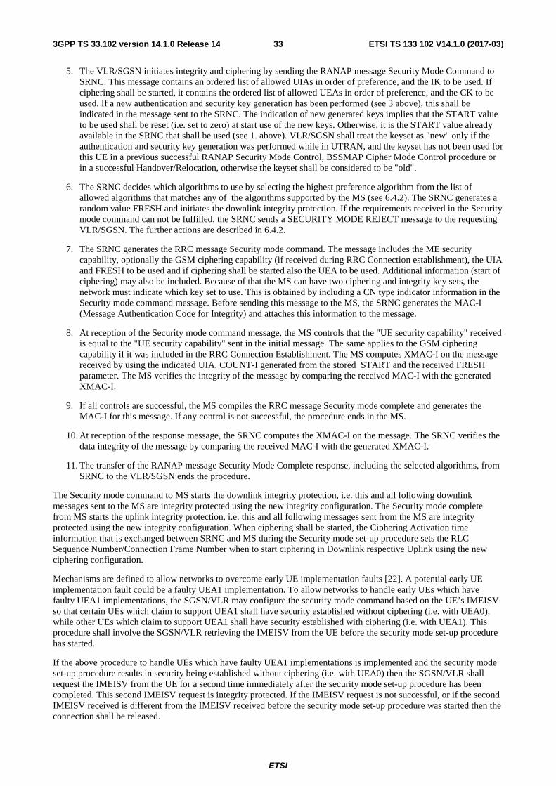
ETSI
ETSI TS 133 102 V14.1.0 (2017-03)333GPP TS 33.102 version 14.1.0 Release 14
5. The VLR/SGSN initiates integrity and ciphering by sending the RANAP message Security Mode Command to SRNC. This message contains an ordered list of allowed UIAs in order of preference, and the IK to be used. If ciphering shall be started, it contains the ordered list of allowed UEAs in order of preference, and the CK to be used. If a new authentication and security key generation has been performed (see 3 above), this shall be indicated in the message sent to the SRNC. The indication of new generated keys implies that the START value to be used shall be reset (i.e. set to zero) at start use of the new keys. Otherwise, it is the START value already available in the SRNC that shall be used (see 1. above). VLR/SGSN shall treat the keyset as "new" only if the authentication and security key generation was performed while in UTRAN, and the keyset has not been used for this UE in a previous successful RANAP Security Mode Control, BSSMAP Cipher Mode Control procedure or in a successful Handover/Relocation, otherwise the keyset shall be considered to be "old".
6. The SRNC decides which algorithms to use by selecting the highest preference algorithm from the list of allowed algorithms that matches any of the algorithms supported by the MS (see 6.4.2). The SRNC generates a random value FRESH and initiates the downlink integrity protection. If the requirements received in the Security mode command can not be fulfilled, the SRNC sends a SECURITY MODE REJECT message to the requesting VLR/SGSN. The further actions are described in 6.4.2.
7. The SRNC generates the RRC message Security mode command. The message includes the ME security capability, optionally the GSM ciphering capability (if received during RRC Connection establishment), the UIA and FRESH to be used and if ciphering shall be started also the UEA to be used. Additional information (start of ciphering) may also be included. Because of that the MS can have two ciphering and integrity key sets, the network must indicate which key set to use. This is obtained by including a CN type indicator information in the Security mode command message. Before sending this message to the MS, the SRNC generates the MAC-I (Message Authentication Code for Integrity) and attaches this information to the message.
8. At reception of the Security mode command message, the MS controls that the "UE security capability" received is equal to the "UE security capability" sent in the initial message. The same applies to the GSM ciphering capability if it was included in the RRC Connection Establishment. The MS computes XMAC-I on the message received by using the indicated UIA, COUNT-I generated from the stored START and the received FRESH parameter. The MS verifies the integrity of the message by comparing the received MAC-I with the generated XMAC-I.
9. If all controls are successful, the MS compiles the RRC message Security mode complete and generates the MAC-I for this message. If any control is not successful, the procedure ends in the MS.
10. At reception of the response message, the SRNC computes the XMAC-I on the message. The SRNC verifies the data integrity of the message by comparing the received MAC-I with the generated XMAC-I.
11. The transfer of the RANAP message Security Mode Complete response, including the selected algorithms, from SRNC to the VLR/SGSN ends the procedure.
The Security mode command to MS starts the downlink integrity protection, i.e. this and all following downlink messages sent to the MS are integrity protected using the new integrity configuration. The Security mode complete from MS starts the uplink integrity protection, i.e. this and all following messages sent from the MS are integrity protected using the new integrity configuration. When ciphering shall be started, the Ciphering Activation time information that is exchanged between SRNC and MS during the Security mode set-up procedure sets the RLC Sequence Number/Connection Frame Number when to start ciphering in Downlink respective Uplink using the new ciphering configuration.
Mechanisms are defined to allow networks to overcome early UE implementation faults [22]. A potential early UE implementation fault could be a faulty UEA1 implementation. To allow networks to handle early UEs which have faulty UEA1 implementations, the SGSN/VLR may configure the security mode command based on the UE’s IMEISV so that certain UEs which claim to support UEA1 shall have security established without ciphering (i.e. with UEA0), while other UEs which claim to support UEA1 shall have security established with ciphering (i.e. with UEA1). This procedure shall involve the SGSN/VLR retrieving the IMEISV from the UE before the security mode set-up procedure has started.
If the above procedure to handle UEs which have faulty UEA1 implementations is implemented and the security mode set-up procedure results in security being established without ciphering (i.e. with UEA0) then the SGSN/VLR shall request the IMEISV from the UE for a second time immediately after the security mode set-up procedure has been completed. This second IMEISV request is integrity protected. If the IMEISV request is not successful, or if the second IMEISV received is different from the IMEISV received before the security mode set-up procedure was started then the connection shall be released.
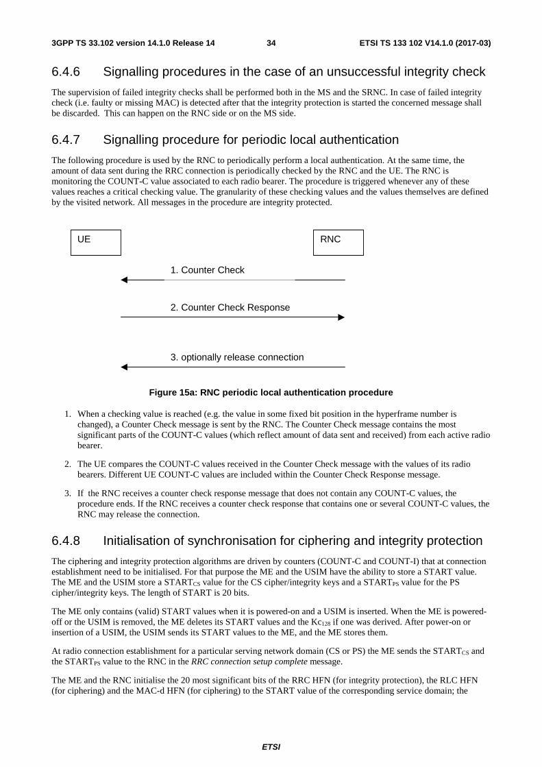
ETSI
ETSI TS 133 102 V14.1.0 (2017-03)343GPP TS 33.102 version 14.1.0 Release 14
6.4.6 Signalling procedures in the case of an unsuccessful integrity check
The supervision of failed integrity checks shall be performed both in the MS and the SRNC. In case of failed integrity check (i.e. faulty or missing MAC) is detected after that the integrity protection is started the concerned message shall be discarded. This can happen on the RNC side or on the MS side.
6.4.7 Signalling procedure for periodic local authentication
The following procedure is used by the RNC to periodically perform a local authentication. At the same time, the amount of data sent during the RRC connection is periodically checked by the RNC and the UE. The RNC is monitoring the COUNT-C value associated to each radio bearer. The procedure is triggered whenever any of these values reaches a critical checking value. The granularity of these checking values and the values themselves are defined by the visited network. All messages in the procedure are integrity protected.
UE RNC
1. Counter Check
2. Counter Check Response
3. optionally release connection
Figure 15a: RNC periodic local authentication procedure
1. When a checking value is reached (e.g. the value in some fixed bit position in the hyperframe number is changed), a Counter Check message is sent by the RNC. The Counter Check message contains the most significant parts of the COUNT-C values (which reflect amount of data sent and received) from each active radio bearer.
2. The UE compares the COUNT-C values received in the Counter Check message with the values of its radio bearers. Different UE COUNT-C values are included within the Counter Check Response message.
3. If the RNC receives a counter check response message that does not contain any COUNT-C values, the procedure ends. If the RNC receives a counter check response that contains one or several COUNT-C values, the RNC may release the connection.
6.4.8 Initialisation of synchronisation for ciphering and integrity protection
The ciphering and integrity protection algorithms are driven by counters (COUNT-C and COUNT-I) that at connection establishment need to be initialised. For that purpose the ME and the USIM have the ability to store a START value. The ME and the USIM store a STARTCS value for the CS cipher/integrity keys and a STARTPS value for the PS cipher/integrity keys. The length of START is 20 bits.
The ME only contains (valid) START values when it is powered-on and a USIM is inserted. When the ME is powered-off or the USIM is removed, the ME deletes its START values and the Kc128 if one was derived. After power-on or insertion of a USIM, the USIM sends its START values to the ME, and the ME stores them.
At radio connection establishment for a particular serving network domain (CS or PS) the ME sends the STARTCS and the STARTPS value to the RNC in the RRC connection setup complete message.
The ME and the RNC initialise the 20 most significant bits of the RRC HFN (for integrity protection), the RLC HFN (for ciphering) and the MAC-d HFN (for ciphering) to the START value of the corresponding service domain; the
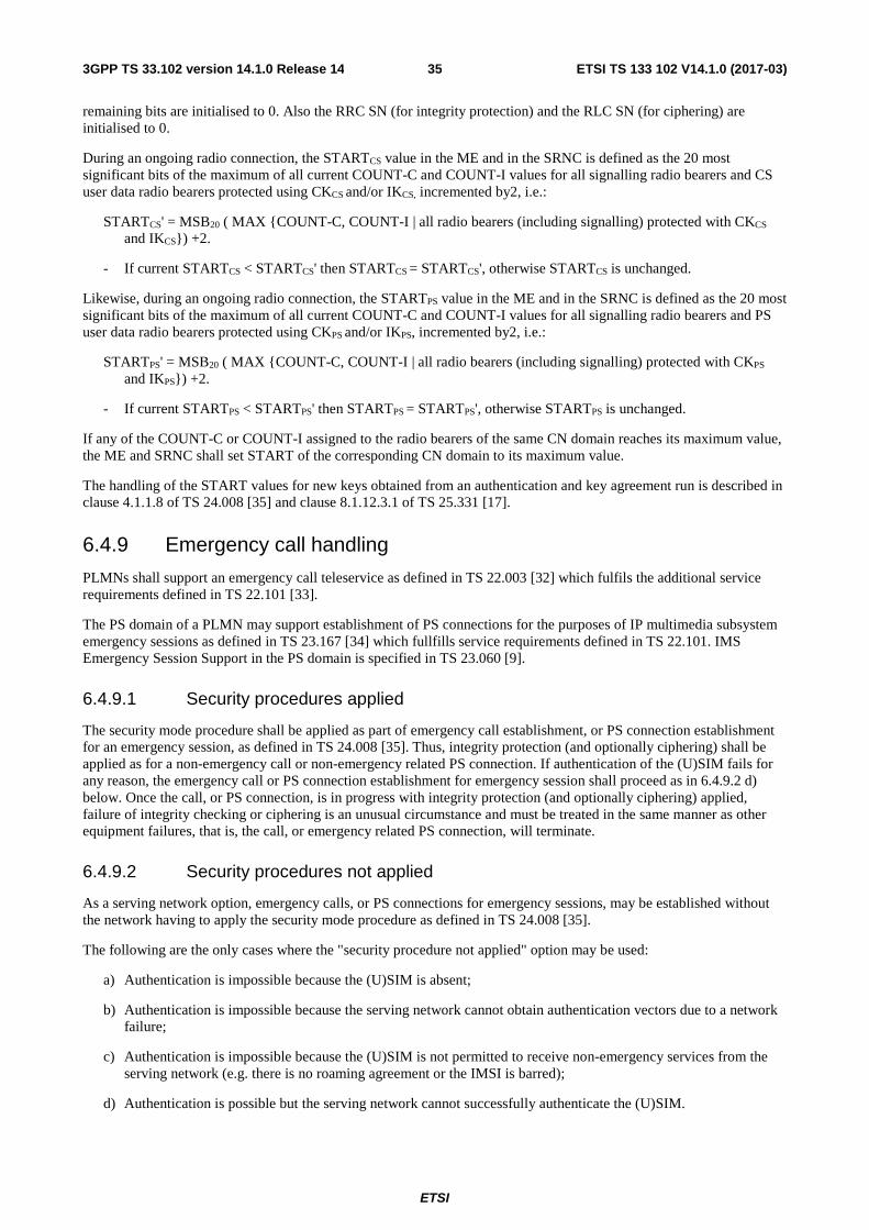
ETSI
ETSI TS 133 102 V14.1.0 (2017-03)353GPP TS 33.102 version 14.1.0 Release 14
remaining bits are initialised to 0. Also the RRC SN (for integrity protection) and the RLC SN (for ciphering) are initialised to 0.
During an ongoing radio connection, the STARTCS value in the ME and in the SRNC is defined as the 20 most significant bits of the maximum of all current COUNT-C and COUNT-I values for all signalling radio bearers and CS user data radio bearers protected using CKCS and/or IKCS, incremented by2, i.e.:
STARTCS' = MSB20 ( MAX {COUNT-C, COUNT-I | all radio bearers (including signalling) protected with CKCS
and IKCS}) +2.
- If current STARTCS < STARTCS' then STARTCS = STARTCS', otherwise STARTCS is unchanged.
Likewise, during an ongoing radio connection, the STARTPS value in the ME and in the SRNC is defined as the 20 most significant bits of the maximum of all current COUNT-C and COUNT-I values for all signalling radio bearers and PS user data radio bearers protected using CKPS and/or IKPS, incremented by2, i.e.:
STARTPS' = MSB20 ( MAX {COUNT-C, COUNT-I | all radio bearers (including signalling) protected with CKPS
and IKPS}) +2.
- If current STARTPS < STARTPS' then STARTPS = STARTPS', otherwise STARTPS is unchanged.
If any of the COUNT-C or COUNT-I assigned to the radio bearers of the same CN domain reaches its maximum value, the ME and SRNC shall set START of the corresponding CN domain to its maximum value.
The handling of the START values for new keys obtained from an authentication and key agreement run is described in clause 4.1.1.8 of TS 24.008 [35] and clause 8.1.12.3.1 of TS 25.331 [17].
6.4.9 Emergency call handling
PLMNs shall support an emergency call teleservice as defined in TS 22.003 [32] which fulfils the additional service requirements defined in TS 22.101 [33].
The PS domain of a PLMN may support establishment of PS connections for the purposes of IP multimedia subsystem emergency sessions as defined in TS 23.167 [34] which fullfills service requirements defined in TS 22.101. IMS Emergency Session Support in the PS domain is specified in TS 23.060 [9].
6.4.9.1 Security procedures applied
The security mode procedure shall be applied as part of emergency call establishment, or PS connection establishment for an emergency session, as defined in TS 24.008 [35]. Thus, integrity protection (and optionally ciphering) shall be applied as for a non-emergency call or non-emergency related PS connection. If authentication of the (U)SIM fails for any reason, the emergency call or PS connection establishment for emergency session shall proceed as in 6.4.9.2 d) below. Once the call, or PS connection, is in progress with integrity protection (and optionally ciphering) applied, failure of integrity checking or ciphering is an unusual circumstance and must be treated in the same manner as other equipment failures, that is, the call, or emergency related PS connection, will terminate.
6.4.9.2 Security procedures not applied
As a serving network option, emergency calls, or PS connections for emergency sessions, may be established without the network having to apply the security mode procedure as defined in TS 24.008 [35].
The following are the only cases where the "security procedure not applied" option may be used:
a) Authentication is impossible because the (U)SIM is absent;
b) Authentication is impossible because the serving network cannot obtain authentication vectors due to a network failure;
c) Authentication is impossible because the (U)SIM is not permitted to receive non-emergency services from the serving network (e.g. there is no roaming agreement or the IMSI is barred);
d) Authentication is possible but the serving network cannot successfully authenticate the (U)SIM.
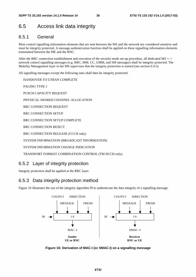
ETSI
ETSI TS 133 102 V14.1.0 (2017-03)363GPP TS 33.102 version 14.1.0 Release 14
6.5 Access link data integrity
6.5.1 General
Most control signalling information elements that are sent between the MS and the network are considered sensitive and must be integrity protected. A message authentication function shall be applied on these signalling information elements transmitted between the ME and the RNC.
After the RRC connection establishment and execution of the security mode set-up procedure, all dedicated MS <–> network control signalling messages (e.g. RRC, MM, CC, GMM, and SM messages) shall be integrity protected. The Mobility Management layer in the MS supervises that the integrity protection is started (see section 6.4.5).
All signalling messages except the following ones shall then be integrity protected:
HANDOVER TO UTRAN COMPLETE
PAGING TYPE 1
PUSCH CAPACITY REQUEST
PHYSICAL SHARED CHANNEL ALLOCATION
RRC CONNECTION REQUEST
RRC CONNECTION SETUP
RRC CONNECTION SETUP COMPLETE
RRC CONNECTION REJECT
RRC CONNECTION RELEASE (CCCH only)
SYSTEM INFORMATION (BROADCAST INFORMATION)
SYSTEM INFORMATION CHANGE INDICATION
TRANSPORT FORMAT COMBINATION CONTROL (TM DCCH only)
6.5.2 Layer of integrity protection
Integrity protection shall be applied at the RRC layer.
6.5.3 Data integrity protection method
Figure 16 illustrates the use of the integrity algorithm f9 to authenticate the data integrity of a signalling message.
f 9
COUNT-I DIRECTION
MESSAGE FRESH
IK
MAC -I
f 9
COUNT-I DIRECTION
MESSAGE FRESH
IK
XMAC -I
SenderUE or RNC
ReceiverRNC or UE
Figure 16: Derivation of MAC-I (or XMAC-I) on a signalling message
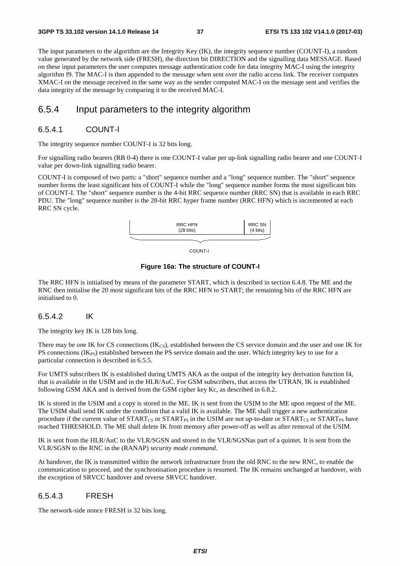
ETSI
ETSI TS 133 102 V14.1.0 (2017-03)373GPP TS 33.102 version 14.1.0 Release 14
The input parameters to the algorithm are the Integrity Key (IK), the integrity sequence number (COUNT-I), a random value generated by the network side (FRESH), the direction bit DIRECTION and the signalling data MESSAGE. Based on these input parameters the user computes message authentication code for data integrity MAC-I using the integrity algorithm f9. The MAC-I is then appended to the message when sent over the radio access link. The receiver computes XMAC-I on the message received in the same way as the sender computed MAC-I on the message sent and verifies the data integrity of the message by comparing it to the received MAC-I.
6.5.4 Input parameters to the integrity algorithm
6.5.4.1 COUNT-I
The integrity sequence number COUNT-I is 32 bits long.
For signalling radio bearers (RB 0-4) there is one COUNT-I value per up-link signalling radio bearer and one COUNT-I value per down-link signalling radio bearer.
COUNT-I is composed of two parts: a "short" sequence number and a "long" sequence number. The "short" sequence number forms the least significant bits of COUNT-I while the "long" sequence number forms the most significant bits of COUNT-I. The "short" sequence number is the 4-bit RRC sequence number (RRC SN) that is available in each RRC PDU. The "long" sequence number is the 28-bit RRC hyper frame number (RRC HFN) which is incremented at each RRC SN cycle.
RRC HFN(28 bits)
RRC SN(4 bits)
COUNT-I
Figure 16a: The structure of COUNT-I
The RRC HFN is initialised by means of the parameter START, which is described in section 6.4.8. The ME and the RNC then initialise the 20 most significant bits of the RRC HFN to START; the remaining bits of the RRC HFN are initialised to 0.
6.5.4.2 IK
The integrity key IK is 128 bits long.
There may be one IK for CS connections (IKCS), established between the CS service domain and the user and one IK for PS connections (IKPS) established between the PS service domain and the user. Which integrity key to use for a particular connection is described in 6.5.5.
For UMTS subscribers IK is established during UMTS AKA as the output of the integrity key derivation function f4, that is available in the USIM and in the HLR/AuC. For GSM subscribers, that access the UTRAN, IK is established following GSM AKA and is derived from the GSM cipher key Kc, as described in 6.8.2.
IK is stored in the USIM and a copy is stored in the ME. IK is sent from the USIM to the ME upon request of the ME. The USIM shall send IK under the condition that a valid IK is available. The ME shall trigger a new authentication procedure if the current value of STARTCS or STARTPS in the USIM are not up-to-date or STARTCS or STARTPS have reached THRESHOLD. The ME shall delete IK from memory after power-off as well as after removal of the USIM.
IK is sent from the HLR/AuC to the VLR/SGSN and stored in the VLR/SGSNas part of a quintet. It is sent from the VLR/SGSN to the RNC in the (RANAP) security mode command.
At handover, the IK is transmitted within the network infrastructure from the old RNC to the new RNC, to enable the communication to proceed, and the synchronisation procedure is resumed. The IK remains unchanged at handover, with the exception of SRVCC handover and reverse SRVCC handover.
6.5.4.3 FRESH
The network-side nonce FRESH is 32 bits long.
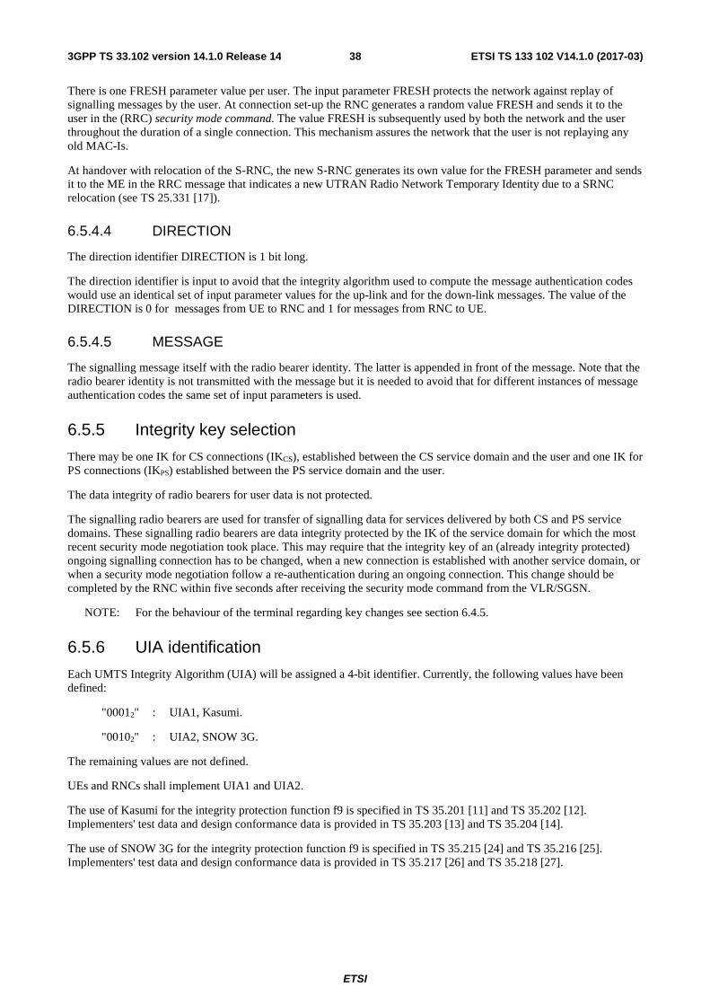
ETSI
ETSI TS 133 102 V14.1.0 (2017-03)383GPP TS 33.102 version 14.1.0 Release 14
There is one FRESH parameter value per user. The input parameter FRESH protects the network against replay of signalling messages by the user. At connection set-up the RNC generates a random value FRESH and sends it to the user in the (RRC) security mode command. The value FRESH is subsequently used by both the network and the user throughout the duration of a single connection. This mechanism assures the network that the user is not replaying any old MAC-Is.
At handover with relocation of the S-RNC, the new S-RNC generates its own value for the FRESH parameter and sends it to the ME in the RRC message that indicates a new UTRAN Radio Network Temporary Identity due to a SRNC relocation (see TS 25.331 [17]).
6.5.4.4 DIRECTION
The direction identifier DIRECTION is 1 bit long.
The direction identifier is input to avoid that the integrity algorithm used to compute the message authentication codes would use an identical set of input parameter values for the up-link and for the down-link messages. The value of the DIRECTION is 0 for messages from UE to RNC and 1 for messages from RNC to UE.
6.5.4.5 MESSAGE
The signalling message itself with the radio bearer identity. The latter is appended in front of the message. Note that the radio bearer identity is not transmitted with the message but it is needed to avoid that for different instances of message authentication codes the same set of input parameters is used.
6.5.5 Integrity key selection
There may be one IK for CS connections (IKCS), established between the CS service domain and the user and one IK for PS connections (IKPS) established between the PS service domain and the user.
The data integrity of radio bearers for user data is not protected.
The signalling radio bearers are used for transfer of signalling data for services delivered by both CS and PS service domains. These signalling radio bearers are data integrity protected by the IK of the service domain for which the most recent security mode negotiation took place. This may require that the integrity key of an (already integrity protected) ongoing signalling connection has to be changed, when a new connection is established with another service domain, or when a security mode negotiation follow a re-authentication during an ongoing connection. This change should be completed by the RNC within five seconds after receiving the security mode command from the VLR/SGSN.
NOTE: For the behaviour of the terminal regarding key changes see section 6.4.5.
6.5.6 UIA identification
Each UMTS Integrity Algorithm (UIA) will be assigned a 4-bit identifier. Currently, the following values have been defined:
"00012" : UIA1, Kasumi.
"00102" : UIA2, SNOW 3G.
The remaining values are not defined.
UEs and RNCs shall implement UIA1 and UIA2.
The use of Kasumi for the integrity protection function f9 is specified in TS 35.201 [11] and TS 35.202 [12]. Implementers' test data and design conformance data is provided in TS 35.203 [13] and TS 35.204 [14].
The use of SNOW 3G for the integrity protection function f9 is specified in TS 35.215 [24] and TS 35.216 [25]. Implementers' test data and design conformance data is provided in TS 35.217 [26] and TS 35.218 [27].
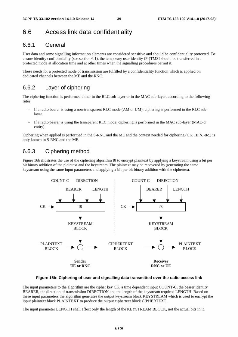
ETSI
ETSI TS 133 102 V14.1.0 (2017-03)393GPP TS 33.102 version 14.1.0 Release 14
6.6 Access link data confidentiality
6.6.1 General
User data and some signalling information elements are considered sensitive and should be confidentiality protected. To ensure identity confidentiality (see section 6.1), the temporary user identity (P-)TMSI should be transferred in a protected mode at allocation time and at other times when the signalling procedures permit it.
These needs for a protected mode of transmission are fulfilled by a confidentiality function which is applied on dedicated channels between the ME and the RNC.
6.6.2 Layer of ciphering
The ciphering function is performed either in the RLC sub-layer or in the MAC sub-layer, according to the following rules:
- If a radio bearer is using a non-transparent RLC mode (AM or UM), ciphering is performed in the RLC sub-layer.
- If a radio bearer is using the transparent RLC mode, ciphering is performed in the MAC sub-layer (MAC-d entity).
Ciphering when applied is performed in the S-RNC and the ME and the context needed for ciphering (CK, HFN, etc.) is only known in S-RNC and the ME.
6.6.3 Ciphering method
Figure 16b illustrates the use of the ciphering algorithm f8 to encrypt plaintext by applying a keystream using a bit per bit binary addition of the plaintext and the keystream. The plaintext may be recovered by generating the same keystream using the same input parameters and applying a bit per bit binary addition with the ciphertext.
PLAINTEXTBLOCK
f8
COUNT-C DIRECTION
BEARER LENGTH
CK
KEYSTREAMBLOCK
CIPHERTEXTBLOCK
f8
COUNT-C DIRECTION
BEARER LENGTH
CK
KEYSTREAMBLOCK
PLAINTEXTBLOCK
SenderUE or RNC
ReceiverRNC or UE
Figure 16b: Ciphering of user and signalling data transmitted over the radio access link
The input parameters to the algorithm are the cipher key CK, a time dependent input COUNT-C, the bearer identity BEARER, the direction of transmission DIRECTION and the length of the keystream required LENGTH. Based on these input parameters the algorithm generates the output keystream block KEYSTREAM which is used to encrypt the input plaintext block PLAINTEXT to produce the output ciphertext block CIPHERTEXT.
The input parameter LENGTH shall affect only the length of the KEYSTREAM BLOCK, not the actual bits in it.
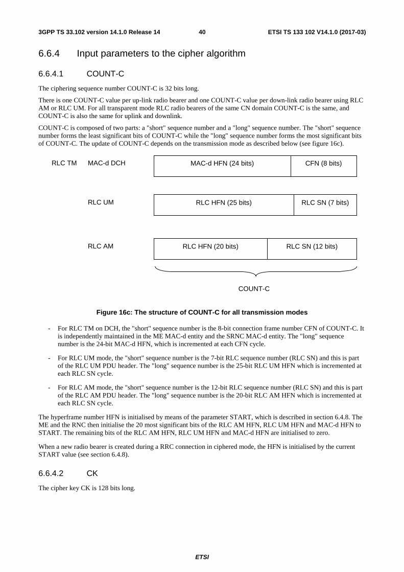
ETSI
ETSI TS 133 102 V14.1.0 (2017-03)403GPP TS 33.102 version 14.1.0 Release 14
6.6.4 Input parameters to the cipher algorithm
6.6.4.1 COUNT-C
The ciphering sequence number COUNT-C is 32 bits long.
There is one COUNT-C value per up-link radio bearer and one COUNT-C value per down-link radio bearer using RLC AM or RLC UM. For all transparent mode RLC radio bearers of the same CN domain COUNT-C is the same, and COUNT-C is also the same for uplink and downlink.
COUNT-C is composed of two parts: a "short" sequence number and a "long" sequence number. The "short" sequence number forms the least significant bits of COUNT-C while the "long" sequence number forms the most significant bits of COUNT-C. The update of COUNT-C depends on the transmission mode as described below (see figure 16c).
Figure 16c: The structure of COUNT-C for all transmission modes
- For RLC TM on DCH, the "short" sequence number is the 8-bit connection frame number CFN of COUNT-C. It is independently maintained in the ME MAC-d entity and the SRNC MAC-d entity. The "long" sequence number is the 24-bit MAC-d HFN, which is incremented at each CFN cycle.
- For RLC UM mode, the "short" sequence number is the 7-bit RLC sequence number (RLC SN) and this is part of the RLC UM PDU header. The "long" sequence number is the 25-bit RLC UM HFN which is incremented at each RLC SN cycle.
- For RLC AM mode, the "short" sequence number is the 12-bit RLC sequence number (RLC SN) and this is part of the RLC AM PDU header. The "long" sequence number is the 20-bit RLC AM HFN which is incremented at each RLC SN cycle.
The hyperframe number HFN is initialised by means of the parameter START, which is described in section 6.4.8. The ME and the RNC then initialise the 20 most significant bits of the RLC AM HFN, RLC UM HFN and MAC-d HFN to START. The remaining bits of the RLC AM HFN, RLC UM HFN and MAC-d HFN are initialised to zero.
When a new radio bearer is created during a RRC connection in ciphered mode, the HFN is initialised by the current START value (see section 6.4.8).
6.6.4.2 CK
The cipher key CK is 128 bits long.
MAC-d HFN (24 bits) CFN (8 bits)MAC-d DCH
RLC HFN (25 bits) RLC SN (7 bits)RLC UM
RLC HFN (20 bits) RLC SN (12 bits)RLC AM
RLC TM
COUNT-C
ETSI
ETSI TS 133 102 V14.1.0 (2017-03)413GPP TS 33.102 version 14.1.0 Release 14
There may be one CK for CS connections (CKCS), established between the CS service domain and the user and one CK for PS connections (CKPS) established between the PS service domain and the user. The CK to use for a particular radio bearer is described in 6.6.5. For UMTS subscribers, CK is established during UMTS AKA, as the output of the cipher key derivation function f3, available in the USIM and in HLR/AuC. For GSM subscribers that access the UTRAN, CK is established following GSM AKA and is derived from the GSM cipher key Kc, as described in 8.2.
CK is stored in the USIM and a copy is stored in the ME. CK is sent from the USIM to the ME upon request of the ME. The USIM shall send CK under the condition that a valid CK is available. The ME shall trigger a new authentication procedure if the current value of STARTCS or STARTPS in the USIM have reached THRESHOLD. The ME shall delete CK from memory after power-off as well as after removal of the USIM.
CK is sent from the HLR/AuC to the VLR/SGSN and stored in the VLR/SGSN as part of the quintet. It is sent from the VLR/SGSN to the RNC in the (RANAP) security mode command.
At handover, the CK is transmitted within the network infrastructure from the old RNC to the new RNC, to enable the communication to proceed. The cipher CK remains unchanged at handover, with the exception of SRVCC handover and reverse SRVCC handover.
6.6.4.3 BEARER
The radio bearer identifier BEARER is 5 bits long.
There is one BEARER parameter per radio bearer associated with the same user and multiplexed on a single 10ms physical layer frame. The radio bearer identifier is input to avoid that for different keystream an identical set of input parameter values is used.
6.6.4.4 DIRECTION
The direction identifier DIRECTION is 1 bit long.
The direction identifier is input to avoid that for the keystreams for the up-link and for the down-link would use the an identical set of input parameter values. The value of the DIRECTION is 0 for messages from UE to RNC and 1 for messages from RNC to UE.
6.6.4.5 LENGTH
The length indicator LENGTH is 16 bits long.
The length indicator determines the length of the required keystream block. LENGTH shall affect only the length of the KEYSTREAM BLOCK, not the actual bits in it.
6.6.5 Cipher key selection
There is one CK for CS connections (CKCS), established between the CS service domain and the user and one CK for PS connections (CKPS) established between the PS service domain and the user.
The radio bearers for CS user data are ciphered with CKCS.
The radio bearers for PS user data are ciphered with CKPS.
The signalling radio bearers are used for transfer of signalling data for services delivered by both CS and PS service domains. These signalling radio bearers are ciphered by the CK of the service domain for which the most recent security mode negotiation took place. This may require that the cipher key of an (already ciphered) ongoing signalling connection has to be changed, when a new connection is established with another service domain, or when a security mode negotiation follows a re-authentication during an ongoing connection. This change should be completed by the RNC within five seconds after receiving the security mode command from the VLR/SGSN.
NOTE: For the behaviour of the terminal regarding key changes see section 6.4.5.
ETSI
ETSI TS 133 102 V14.1.0 (2017-03)423GPP TS 33.102 version 14.1.0 Release 14
6.6.6 UEA identification
Each UEA will be assigned a 4-bit identifier. Currently the following values have been defined:
"00002" : UEA0, no encryption.
"00012" : UEA1, Kasumi.
"00102" : UEA2, SNOW 3G.
The remaining values are not defined.
UEs shall implement UEA0, UEA1 and UEA2.
The use of Kasumi for the ciphering function f8 is specified in TS 35.201 [11] and TS 35.202 [12]. Implementers' test data and design conformance data is provided in TS 35.203 [13] and TS 35.204 [14].
The use of SNOW 3G for the ciphering function f8 is specified in TS 35.215 [24] and TS 35.216 [25]. Implementers' test data and design conformance data is provided in TS 35.217 [26] and TS 35.218 [27].
6.7 Void
6.8 Interoperation and handover between UMTS and GSM
6.8.1 Authentication and key agreement of UMTS subscribers
6.8.1.1 General
For UMTS subscribers, authentication and key agreement will be performed as follows:
- UMTS AKA shall be applied when the user is attached to a UTRAN.
- UMTS AKA shall be applied when the user is attached to a GSM BSS, in case the user has a ME capable of UMTS AKA and also the VLR/SGSN is R99+. In this case, the 64-bit GSM cipher key Kc is derived from the UMTS cipher/integrity keys CK and IK, by the VLR/SGSN on the network side and by the USIM on the user side.The 128-bit GSM cipher key Kc128 is derived from the UMTS cipher/integrity keys CK and IK, by the VLR/SGSN on the network side and by the ME on the user side if needed to support 128-bit ciphering algorithms in GSM as described in subclause 6.3.3 of this specification.
- GSM AKA shall be applied when the user is attached to a GSM BSS, in case the user has a ME not capable of UMTS AKA. In this case, the GSM user response SRES and the 64-bit GSM cipher key Kc are derived from the UMTS user response RES and the UMTS cipher/integrity keys CK and IK. A R98- VLR/SGSN uses the stored Kc and RES and a R99+ VLR/SGSN derives the SRES from RES and Kc from CK, IK.
NOTE: To operate within a ME not capable of UMTS AKA, the USIM may support the SIM-ME interface as defined in GSM 11.11, and support GSM AKA which provides the corresponding GSM functionality for calculating SRES and Kc based on the authentication key K and the 3G authentication algorithm implemented in the USIM. Due to the fact that the UMTS authentication algorithm only computes CK/IK and RES, conversion of CK/IK to Kc shall be achieved by using the conversion function c3, and conversion of RES to SRES by c2.
- GSM AKA shall be applied when the user is attached to a GSM BSS, in case the VLR/SGSN is R98-. In this case, the USIM derives the GSM user response SRES and the GSM cipher key Kc from the UMTS user response RES and the UMTS cipher/integrity keys CK, IK.
The execution of the UMTS (resp. GSM) AKA results in the establishment of a UMTS (resp. GSM) security context between the user and the serving network domain to which the VLR/SGSN belongs. The user needs to separately establish a security context with each serving network domain.

ETSI
ETSI TS 133 102 V14.1.0 (2017-03)433GPP TS 33.102 version 14.1.0 Release 14
Figure 18 shows the different scenarios that can occur with UMTS subscribers in a mixed network architecture.
Release 99+ VLR/SGSN Release 98- VLR/SGSN
Release 99+ HLR/AuC
USIM
RAND AUTN
RES
CK IK
CK, IK Kc
UTRAN
ME capable of UMTS AKA
RAND AUTN RES
[Kc]
CK, IK Kc
GSM BSS
CK, IK � Kc
ME not capable of UMTS
AKA
CK, IK � Kc
RAND [ AUTN] SRES
[Kc]
Kc
RAND SRES
[Kc]
Kc
ME
Quintets Triplets
CK, IK�Kc RES�SRES
UMTS security context
GSM security context
CK, IK � Kc CK, IK�Kc RES�SRES
CK, IK�Kc RES�SRES
CK, IK�Kc RES�SRES
Release 9+ VLR/SGSN CK, IK�Kc CK, IK�Kc 128
[Kc] Kc128
Kc CK, IK
RAND AUTN RE S
CK, IK�Kc
CK, IK�Kc128
ME capable of A5/n or GEAn, n >= 4
Figure 18: Authentication and key agreement of UMTS subscribers
Note that the UMTS parameters RAND, AUTN and RES are sent transparently through the UTRAN or GSM BSS and that the GSM parameters RAND and SRES are sent transparently through the GSM BSS.
In case of a GSM BSS, ciphering is applied in the GSM BSS for services delivered via the MSC/VLR, and by the SGSN for services delivered via the SGSN. In the latter case the GSM cipher keys Kc or Kc128 are not sent to the GSM BSS.
In case of a UTRAN, ciphering and integrity are always applied in the RNC, and the UMTS cipher/integrity keys CK an IK are always sent to the RNC.
6.8.1.2 R99+ HLR/AuC
Upon receipt of an authentication data request from a R99+ VLR/SGSN for a UMTS subscriber, a R99+ HLR/AuC shall send quintets, generated as specified in 6.3.
Upon receipt of an authentication data request from a R98- VLR/SGSN for a UMTS subscriber, a R99+ HLR/AuC shall send triplets, derived from quintets using the following conversion functions:
a) c1: RAND[GSM] = RAND
b) c2: SRES[GSM] = XRES*1 xor XRES*2 xor XRES*3 xor XRES*4
c) c3: Kc[GSM] = CK1 xor CK2 xor IK1 xor IK2
ETSI
ETSI TS 133 102 V14.1.0 (2017-03)443GPP TS 33.102 version 14.1.0 Release 14
whereby XRES* is 16 octets long and XRES* = XRES if XRES is 16 octets long and XRES* = XRES || 0...0 if XRES is shorter than 16 octets, XRES*i are all 4 octets long and XRES* = XRES*1 || XRES*2 || XRES*3 || XRES*4, CKi and IKi are both 64 bits long and CK = CK1 || CK2 and IK = IK1 || IK2
6.8.1.3 R99+ VLR/SGSN
The AKA procedure will depend on the terminal capabilities, as follows:
UMTS subscriber with R99+ ME
When the user has R99+ ME, the VLR/SGSN shall send the ME a UMTS authentication challenge (i.e. RAND and AUTN) using a quintet that is either:
a) retrieved from the local database,
b) provided by the HLR/AuC, or
c) provided by the previously visited R99+ VLR/SGSN.
Note: Originally all quintets are provided by the HLR/AuC.
When the ME is capable of the USIM-ME interface, then UMTS AKA is performed and the VLR/SGSN receives the UMTS response RES.
UMTS AKA results in the establishment of a UMTS security context; the UMTS cipher/integrity keys CK and IK and the key set identifier KSI are stored in theVLR/SGSN.
When the user is attached to a UTRAN, the UMTS cipher/integrity keys are sent to the RNC, where the cipher/integrity algorithms are allocated.
When the user is attached to a GSM BSS, UMTS AKA is followed by the derivation of the GSM cipher keys Kc (and Kc128 when needed)from the UMTS cipher/integrity keys. When the user receives service from an MSC/VLR, the derived cipher keys Kc (and Kc128 when needed) are then sent to the BSC (and forwarded to the BTS). When the user receives service from an SGSN, the derived cipher key Kc or Kc128 applied in the SGSN itself.
UMTS authentication and key freshness is always provided to UMTS subscribers with R99+ ME independently of the radio access network.
When the ME is not capable of the USIM-ME interface, then GSM AKA is performed and the VLR/SGSN receives the GSM response SRES.
GSM AKA results in the establishment of a GSM security context; the 64-bit GSM cipher key Kc and the cipher key sequence number CKSN are stored in the VLR/SGSN.
The R99+ VLR/SGSN shall reject authentication if SRES is received in response of a UMTS challenge (RAND, AUTN) over an Iu-Interface.
The R99+ VLR/SGSN shall accept authentication if a valid SRES is received in response of a UMTS challenge (RAND, AUTN) over A or Gb-Interface. This will happen in case a UICC is inserted in a ME that is not capable of UMTS AKA and is attached to a GSM BSS. In this case the R99+ VLR/SGSN uses function c2 to convert RES (from the quintet) to SRES to verify the received SRES.
UMTS subscriber with R98- ME
When the user has R98- ME, the R99+ VLR/SGSN sends the ME a GSM authentication challenge using a triplet that is either:
a) derived by means of the conversion functions c2 and c3 in the R99+ VLR/SGSN from a quintet that is:
i) retrieved from the local database,
ii) provided by the HLR/AuC, or
iii) provided by the previously visited R99+ VLR/SGSN, or
ETSI
ETSI TS 133 102 V14.1.0 (2017-03)453GPP TS 33.102 version 14.1.0 Release 14
b) provided as a triplet by the previously visited VLR/SGSN.
NOTE 1: R99+ VLR/SGSN will always provide quintets for UMTS subscribers.
NOTE 2: For a UMTS subscriber, all triplets are derived from quintets, be it in the HLR/AuC or in an VLR/SGSN.
GSM AKA results in the establishment of a GSM security context; the 64-bit GSM cipher key Kc and the cipher key sequence number CKSN are stored in the VLR/SGSN.
In this case the user is attached to a GSM BSS. When the user receives service from an MSC/VLR, the 64-bit GSM cipher key is sent to the BSC (and forwarded to the BTS). When the user receives service from an SGSN, the derived cipher key Kc is applied in the SGSN itself.
UMTS authentication and key freshness cannot be provided to UMTS subscriber with R98- ME.
6.8.1.4 R99+ ME
Release 99+ ME that has UTRAN radio capability shall support the USIM-ME interface as specified in TS 31.102 [20].
Rel4- ME that has no UTRAN radio capabilities may support the USIM-ME interface as specified in TS 31.102 [20].
Rel5+ ME that has no UTRAN radio capabilities shall support the USIM-ME interface as specified in TS 31.102 [20].
A ME capable of UMTS AKA with a USIM active and attached to a UTRAN shall only participate in UMTS AKA and shall not participate in GSM AKA.
A ME capable of UMTS AKA with a USIM active and attached to a GSM BSS shall participate in UMTS AKA and may participate in GSM AKA. Participation in GSM AKA is required to allow registration in a R98- VLR/SGSN.
However, the use of GSM AKA in the MS shall be disabled on a particular visited network if instructed to do so by the USIM application. The mechanism is based on an EF ‘Disabled Authentications’ in the USIM application containing the unauthorized authentication methods per visited network. If the EF ‘Disabled Authentications’ is present and active, then the authentication methods marked as disabled shall not be used by the MS in the corresponding visited network. The disabled authentication method may be defined on a global, per country or per network basis. The relevant file in the USIM application is managed by the home operator based on information supplied to the home operator by the visited network.
NOTE 1: It is possible for an attacker to spoof a PLMN id and therefore force the UE to use GSM AKA. This could be mitigated by the UE displaying the country name to the user. Displaying the country name is typically not done by today’s UEs and would have to be added as a new UE function. It should be further noted that the network name displayed to the user could be spoofed by an attacker as the displayed network name may not be based on MCC, MNC received via cell broadcast, but on additional signalling.
NOTE 2: A similar mechanism to enforce the use of particular encryption algorithm(s) in a given network is described in clause 4.9 in TS 43.020.
Editor's note: It is FFS whether disabling GSM AKA on a per network basis successfully achieves the intention of mitigating attacks by false basestations.
A ME that not capable of UMTS AKA with a USIM active can only participate in GSM AKA.
The execution of UMTS AKA results in the establishment of a UMTS security context; the UMTS cipher/integrity keys CK and IK and the key set identifier KSI are passed to the ME. If the USIM supports conversion function c3 and/or GSM AKA, the ME shall also receive a 64-bit GSM cipher key Kc derived at the USIM.
If the ME supports 128-bit ciphering algorithms A5 and/or GEA for GSM, the ME shall also support the key derivation function for Kc128 as specified in annex B.5.The execution of GSM AKA results in the establishment of a GSM security context; the 64-bit GSM cipher key Kc and the cipher key sequence number CKSN are stored in the ME.
6.8.1.5 USIM
The USIM shall support UMTS AKA and may support backwards compatibility with the GSM system, which consists of:
ETSI
ETSI TS 133 102 V14.1.0 (2017-03)463GPP TS 33.102 version 14.1.0 Release 14
Feature 1: 64-bit GSM cipher key derivation (conversion function c3) to access GSM BSS attached to a R99+ VLR/SGSN using a dual-mode R99+ ME;
Feature 2: GSM AKA to access the GSM BSS attached to a R98- VLR/SGSN or when using ME not capable of UMTS AKA;
Feature 3: SIM-ME interface (GSM 11.11) to operate within ME not capable of UMTS AKA.
When the ME provides the USIM with RAND and AUTN, UMTS AKA shall be executed. If the verification of AUTN is successful, the USIM shall respond to the ME with the UMTS user response RES and the UMTS cipher/integrity keys CK and IK. The ME shall store CK and IK as current security context data on the USIM. If the USIM supports access to 64-bit GSM cipher key derivation (feature 1), the USIM shall also derive the 64-bit GSM cipher key Kc from the UMTS cipher/integrity keys CK and IK using conversion function c3 and send the derived Kc to the ME. In case the verification of AUTN is not successful, the USIM shall respond with an appropriate error indication to the ME.
When the ME provides the USIM with only RAND, and the USIM supports GSM AKA (Feature 2), GSM AKA shall be executed. The USIM first computes the UMTS user response RES and the UMTS cipher/integrity keys CK and IK. The USIM then derives the GSM user response SRES and the 64-bit GSM cipher key Kc using the conversion functions c2 and c3 and send the GSM user response SRES and the 64-bit GSM cipher key Kc to the ME. The ME shall store the 64-bit GSM cipher key Kc as the current security context on the USIM.
In case the USIM does not support 64-bit GSM cipher key derivation (Feature 1) or GSM AKA (Feature 2), the ME shall be informed. An ME with a USIM that does not support GSM cipher key derivation (Feature 1) shall not perform the GSM cipher key derivation (conversion function c3) in the ME and therefore cannot operate in any GSM BSS with 64-bit key ciphering enabled. An ME with a USIM that does not support GSM AKA (Feature 2) cannot operate under a R98- VLR/SGSN. A USIM that does not support GSM AKA (Feature 2) cannot work within a ME that is not capable of UMTS AKA.
6.8.2 Authentication and key agreement for GSM subscribers
6.8.2.1 General
For GSM subscribers, GSM AKA shall always be used.
The execution of the GSM AKA results in the establishment of a GSM security context between the user and the serving network domain to which the VLR/SGSN belongs. The user needs to separately establish a security context with each serving network domain.
When in a UTRAN, the UMTS cipher/integrity keys CK and IK are derived from the GSM cipher key Kc by the ME and the VLR/SGSN, both R99+ entities.
Figure 19 shows the different scenarios that can occur with GSM subscribers using either R98- or R99+ ME in a mixed network architecture.

ETSI
ETSI TS 133 102 V14.1.0 (2017-03)473GPP TS 33.102 version 14.1.0 Release 14
GSM security context
Release 99+VLR/SGSN
Release 98-VLR/SGSN
Release 98- or Release 99+HLR/AuC
SIM
RANDSRES
CKIK
Kc
UTRAN
R99+ UE
RANDSRES
[Kc]
Kc
GSM BSS
Kc � CK, IK
R98- UE
Kc � CK, IK
RANDSRES
[Kc]
Kc
RANDSRES
[Kc]
Kc
R99+ UEor
R98- UE
Triplets Triplets
Figure 19: Authentication and key agreement for GSM subscribers
Note that the GSM parameters RAND and RES are sent transparently through the UTRAN or GSM BSS.
In case of a GSM BSS, ciphering is applied in the GSM BSS for services delivered via the MSC/VLR, and by the SGSN for services delivered via the SGSN. In the latter case the GSM cipher key Kc is not sent to the GSM BSS.
In case of a UTRAN, ciphering is always applied in the RNC, and the UMTS cipher/integrity keys CK an IK are always sent to the RNC.
6.8.2.2 R99+ HLR/AuC
Upon receipt of an authentication data request for a GSM subscriber, a R99+ HLR/AuC shall send triplets generated as specified in 3GPP TS 43.020.
6.8.2.3 VLR/SGSN
The R99+ VLR/SGSN shall perform GSM AKA using a triplet that is either:
a) retrieved from the local database,
b) provided by the HLR/AuC, or
c) provided by the previously visited VLR/SGSN.
NOTE: All triplets are originally provided by the HLR/AuC.
GSM AKA results in the establishment of a GSM security context; the GSM cipher key Kc and the cipher key sequence number CKSN are stored in the VLR/SGSN.
ETSI
ETSI TS 133 102 V14.1.0 (2017-03)483GPP TS 33.102 version 14.1.0 Release 14
When the user is attached to a UTRAN, the R99+ VLR/SGSN derives the UMTS cipher/integrity keys from the GSM cipher key using the following conversion functions:
a) c4: CK[UMTS] = Kc || Kc;
b) c5: IK[UMTS] = Kc1 xor Kc2 || Kc || Kc1 xor Kc2;
whereby in c5, Kci are both 32 bits long and Kc = Kc1 || Kc2.
The UMTS cipher/integrity keys are then sent to the RNC where the ciphering and integrity algorithms are allocated.
When the user is attached to a GSM BSS and the user receives service from an MSC/VLR, the cipher key Kc is sent to the BSC (and forwarded to the BTS). When the user receives service from an SGSN, the cipher key Kc is applied in the SGSN itself.
6.8.2.4 R99+ ME
R99+ ME with a SIM inserted, shall participate only in GSM AKA.
GSM AKA results in the establishment of a GSM security context; the GSM cipher key Kc and the cipher key sequence number CKSN are stored in the ME.
When the user is attached to a UTRAN, R99+ ME shall derive the UMTS cipher/integrity keys CK and IK from the GSM cipher key Kc using the conversion functions c4 and c5. The ME shall handle the STARTCS and STARTPS as described in section 6.4.8 with the exception that the START values shall be stored in non-volatile memory on the ME rather than on the GSM SIM. If a different SIM is inserted then the ME shall delete the GSM cipher keys for the PS and CS domain (Kc), the derived UMTS cipher/integrity keys (CK and IK) for the PS and CS domain, and reset the START values to zero. The ME shall then trigger a new authentication and key agreement at the next connection establishment by indicating to the network that no valid keys are available for use using the procedure described in section 6.4.4.
When the user is attached to a UTRAN, a R99+ ME with a SIM inserted shall use a default value of all ones for maximum value of STARTCS or STARTPS. The ME shall handle the maximum value of STARTCS or STARTPS as described in section 6.4.3 with the exception that the maximum value of STARTCS or STARTPS is stored on the ME rather than on the GSM SIM.
6.8.3 Distribution and use of authentication data between VLRs/SGSNs
The distribution of authentication data (unused authentication vectors and/or current security context data) between R99+ VLRs/SGSNs of the same service network domain is performed according to chapter 6.3.4. The following four cases are distinguished related to the distribution of authentication data between VLRs/SGSNs (of the same or different releases). Conditions for the distribution of such data and for its use when received at VLRn/SGSNn are indicated for each case:
a) R99+ VLR/SGSN to R99+ VLR/SGSN
UMTS and GSM authentication vectors can be distributed between R99+ VLRs/SGSNs. Note that originally all authentication vectors (quintets for UMTS subscribers and triplets for GSM subscribers) are provided by the HLR/AuC.
Current security context data can be distributed between R99+ VLRs/SGSNs. VLRn/SGSNn shall not use current security context data received from VLRo/SGSNo to authenticate the subscriber using local authentication in the following cases:
i) Security context to be established at VLRn/SGSNn requires a different set of keys than the one currently in use at VLRo/SGSNo. This change of security context is caused by a change of ME release (R’99 ME �� R’98 ME) when the user registers at VLRn/SGSNn.
ii) Authentication data from VLRo includes 64-bit Kc+CKSN but no unused AVs and the subscriber has a R’99 ME (under GSM BSS or UTRAN). In this situation, VLRn have no indication of whether the subscriber is GSM or UMTS and it is not able to decide whether the 64-bit Kc received can be used (in case the subscriber were a GSM subscriber).
In these two cases, received current security context data shall be discarded and a new AKA procedure shall be performed.
ETSI
ETSI TS 133 102 V14.1.0 (2017-03)493GPP TS 33.102 version 14.1.0 Release 14
b) R98- VLR/SGSN to R98- VLR/SGSN
Only triplets can be distributed between R98- VLRs/SGSNs. Note that originally for GSM subscribers, triplets are generated by HLR/AuC and for UMTS subscribers, they are derived from UMTS authentication vectors by R99+ HLR/AuC. UMTS AKA is not supported and only GSM security context can be established by a R98- VLR/SGSN.
R98- VLRs are not prepared to distribute current security context data.
Since only GSM security context can be established under R98- SGSNs, security context data can be distributed and used between R98- SGSNs.
c) R99+ VLR/SGSN to R98- VLR/SGSN
R99+ VLR/SGSN can distribute to a new R98- VLR/SGSN triplets originally provided by HLR/AuC for GSM subscribers or can derive triplets from stored quintets originally provided by R99+ HLR/AuC for UMTS subscribers. Note that R98- VLR/SGSN can only establish GSM security context.
R99+ VLRs shall not distribute current security context data to R98- VLRs.
Since R98- SGSNs are only prepared to handle GSM security context data, R99+ SGSNs shall only distribute GSM security context data (64-bit Kc, CKSN) to R98- SGSNs.
d) R98- VLR/SGSN to R99+ VLR/SGSN.
In order to not establish a GSM security context for a UMTS subscriber, triplets provided by a R98- VLR/SGSN can only be used by a R99+ VLR/SGSN to establish a GSM security context under GSM-BSS with a R98- ME.
In all other cases, R99+ VLR/SGSN shall request fresh AVs (either triplets or quintets) to HE. In the event, the R99+ VLR/SGSN receives quintets, it shall discard the triplets provided by the R98- VLR/SGSN.
R98- VLRs are not prepared to distribute current security context data.
R98- SGSNs can distribute GSM security context data only. The use of this information at R99+ SGSNn shall be performed according to the conditions stated in a).
6.8.4 Intersystem handover for CS Services – from UTRAN to GSM BSS
If ciphering has been started when an intersystem handover occurs from UTRAN to GSM BSS, the necessary information (e.g. Kc, supported/allowed GSM ciphering algorithms) is transmitted within the system infrastructure before the actual handover is executed to enable the communication to proceed from the old RNC to the new GSM BSS, and to continue the communication in ciphered mode. The RNC may request the MS to send the MS Classmarks 2 and 3 which include information on the GSM ciphering algorithm capabilities of the MS. This is necessary only if the MS Classmarks 2 and 3 were not transmitted from UE to UTRAN during the RRC Connection Establishment. The intersystem handover will imply a change of ciphering algorithm from a UEA to a GSM A5. The GSM BSS includes the selected GSM ciphering mode in the handover command message sent to the MS via the RNC.
The integrity protection of signalling messages is stopped at handover to GSM BSS.
6.8.4.1 UMTS security context
A UMTS security context in UTRAN is only established for a UMTS subscriber with a ME that is capable of UMTS AKA. At the network side, four cases are distinguished:
a) In case of a handover to a GSM BSS controlled by the same MSC/VLR, the MSC/VLR derives the 64-bit GSM cipher key Kc from the UMTS cipher/integrity keys CK and IK used before the intersystem handover (using the conversion function c3) and sends the 64-bit Kc to the target BSC (which forwards it to the BTS). If the MSC/VLR is Rel-9+ and MSC/VLR has included a 128-bit GSM ciphering algorithms as a permitted ciphering algorithm, the MSC/VLR shall also derive the 128-bit ciphering key Kc128 and send also this to the target BSC (which forwards it to the BTS).
b) In case of a handover to a GSM BSS controlled by another MSC/VLR, depending on the capability of the inter-MSC communication protocol version, the initial MSC/VLR sends to the target MSC/VLR the security keys associated with the allowed security algorithms. If the inter-MSC communication protocol version only allows
ETSI
ETSI TS 133 102 V14.1.0 (2017-03)503GPP TS 33.102 version 14.1.0 Release 14
inclusion of the 64-bit GSM security key Kc, and the initial MSC/VLR includes a 64-bit GSM A5 ciphering algorithm as allowed ciphering algorithm, the initial MSC/VLR derives the 64-bit Kc and sends it to the new MSC/VLR. Otherwise, if the inter-MSC communication protocol version allows inclusion of UMTS security keys, the initial MSC/VLR sends, in addition, the UMTS cipher/integrity keys CK and IK used before the intersystem handover to the new MSC/VLR. If the initial MSC/VLR includes a 128-bit GSM A5 ciphering algorithm as an allowed ciphering algorithm, the initial MSC/VLR shall also calculate a Kc128 from the CK/IK and forward this to the new MSC. The new MSC/VLR stores the key(s) and then forwards them to the target BSC (which forwards them to the BTS). The initial MSC/VLR remains the anchor point throughout the service.
At the user side, in either case, the ME applies the derived 64-bit GSM cipher key Kc from the key set which was used before the intersystem handover if the selected GSM ciphering algorithm requires a 64-bit key. If the selected GSM A5 ciphering algorithm requires a 128-bit key, the ME shall apply the derived 128-bit GSM cipher key Kc128 from the key set which was used before the intersystem handover.
6.8.4.2 GSM security context
A GSM security context in UTRAN is only established for a GSM subscribers with a R99+ ME. At the network side, two cases are distinguished:
a) In case of a handover to a GSM BSS controlled by the same MSC/VLR, the MSC/VLR sends the 64-bit GSM cipher key Kc from the key set used before the intersystem handover to the target BSC (which forwards it to the BTS).
b) In case of a handover to a GSM BSS controlled by another MSC/VLR (R99+ or R98-), the initial MSC/VLR sends the 64-bit GSM cipher key Kc from the key set used before the intersystem handover to the BSC via the new MSC/VLR controlling the target BSC. The initial MSC/VLR remains the anchor point throughout the service.
If the non-anchor MSC/VLR is R99+, then the anchor MSC/VLR also derives and sends to the non-anchor MSC/VLR the UMTS cipher/integrity keys CK and IK. The non-anchor MSC/VLR stores all keys. This is done to allow subsequent handovers in a non-anchor R99+ MSC/VLR.
At the user side, in either case, the ME applies the GSM cipher key Kc from the key set which was used before the intersystem handover.
6.8.5 Intersystem handover for CS Services – from GSM BSS to UTRAN
If ciphering has been started when an intersystem handover occurs from GSM BSS to UTRAN, the necessary information (e.g. CK, IK, START value information, supported/allowed UMTS algorithms) is transmitted within the system infrastructure before the actual handover is executed to enable the communication to proceed from the old GSM BSS to the new RNC, and to continue the communication in ciphered mode. The GSM BSS requests the MS to send the UMTS capability information, which includes information on the START values and UMTS security capabilities of the MS. The intersystem handover will imply a change of ciphering algorithm from a GSM A5 to a UEA. The target UMTS RNC includes the selected UMTS ciphering mode in the handover to UTRAN command message sent to the MS via the GSM BSS.
The integrity protection of signalling messages shall be started immediately after the intersystem handover from GSM BSS to UTRAN is completed. The Serving RNC will do this by initiating the RRC security mode control procedure when the first RRC message (i.e. the Handover to UTRAN complete message) has been received from the MS. In this case, the RRC security mode control procedure is initiated by the Serving RNC without receipt of a corresponding RANAP security mode control procedure from the MSC/VLR.The UE security capability information, that has been sent from MS to RNC via the GSM radio access and the system infrastructure before the actual handover execution, will be included in the RRC Security mode command message sent to MS and then verified by the MS (i.e. verified that it is equal to the UE security capability information stored in the MS).
6.8.5.1 UMTS security context
A UMTS security context in GSM BSS is only established for UMTS subscribers with a ME that is capable of UMTS AKA under GSM BSS controlled by a R99+ VLR/SGSN. At the network side, two cases are distinguished:
a) In case of a handover to a UTRAN controlled by the same MSC/VLR, the UMTS cipher/integrity keys CK and IK from the key set used before the intersystem handover are sent to the target RNC.
ETSI
ETSI TS 133 102 V14.1.0 (2017-03)513GPP TS 33.102 version 14.1.0 Release 14
b) In case of a handover to a UTRAN controlled by another MSC/VLR, the initial MSC/VLR sends the UMTS cipher/integrity keys CK and IK from the key set used before the intersystem handover to the new RNC via the new MSC/VLR that controls the target RNC. The initial MSC/VLR remains the anchor point for throughout the service.
The anchor MSC/VLR also derives and sends to the non-anchor MSC/VLR the 64-bit GSM cipher key Kc, if any 64-bit ciphering algorithm is permitted, and/or the 128-bit ciphering key Kc128 if a 128-bit ciphering algorithm is also permitted. The non-anchor MSC/VLR stores all keys. This is done to allow subsequent handovers in a non-anchor R99+ MSC/VLR.
At the user side, in either case, the ME applies the UMTS cipher/integrity keys CK and IK from the key set which was used before the intersystem handover.
6.8.5.2 GSM security context
Handover from GSM BSS to UTRAN with a GSM security context is possible for a GSM subscriber with a R99+ ME or for a UMTS subscriber with a R99+ ME when the initial MSC/VLR is R98-. At the network side, two cases are distinguished:
a) In case of a handover to a UTRAN controlled by the same MSC/VLR, UMTS cipher/integrity keys CK and IK are derived from the 64-bit GSM cipher key Kc used before the intersystem handover (using the conversion functions c4 and c5) and sent to the target RNC. In case of subsequent handover in a non-anchor R99+ MSC/VLR, a 64-bit GSM cipher key Kc is received for a UMTS subscriber if the anchor MSC/VLR is R98-.
b) In case of a handover to a UTRAN controlled by another MSC/VLR, the initial MSC/VLR (R99+ or R98-) sends the 64-bit GSM cipher key Kc used before the intersystem handover to the new MSC/VLR controlling the target RNC. That MSC/VLR derives UMTS cipher/integrity keys CK and IK which are then forwarded to the target RNC. The initial MSC/VLR remains the anchor point for throughout the service.
At the user side, in either case, the ME derives the UMTS cipher/integrity keys CK and IK from the 64-bit GSM cipher key Kc (using the conversion functions c4 and c5) which was used before the intersystem handover and applies them.
6.8.6 Intersystem change for PS Services – from UTRAN to GSM BSS
6.8.6.1 UMTS security context
A UMTS security context in UTRAN is only established for UMTS subscribers. At the network side, four cases are distinguished:
a) In case of an intersystem change to a GSM BSS controlled by the same SGSN, the SGSN derives the 64-bit GSM cipher key Kc from the UMTS cipher/integrity keys CK and IK agreed during the latest UMTS AKA procedure (using the conversion function c3) and applies it if the selected GEA ciphering algorithm requires a 64-bit key.
b) In case of an intersystem change to a GSM BSS controlled by another R99+ SGSN, the initial SGSN sends the UMTS cipher/integrity keys CK and IK agreed during the latest UMTS AKA procedure to the new SGSN. The new SGSN stores the keys, derives the 64-bit GSM cipher key Kc and applies the latter. The new SGSN becomes the new anchor point for the service.
c) In case of an intersystem change to a GSM BSS controlled by a R98- SGSN, the initial SGSN derives the GSM cipher key Kc from the UMTS cipher/integrity keys CK and IK agreed during the latest UMTS AKA procedure and sends the GSM cipher key Kc to the new SGSN. The new SGSN stores the GSM cipher key Kc and applies it. The new SGSN becomes the new anchor point for the service.
d) In case of a handover to another Rel-9+ SGSN, the initial SGSN sends the UMTS cipher/integrity keys CK and IK agreed at the latest UMTS AKA procedure to the new SGSN. The new SGSN derives the 64-bit Kc. The new SGSN stores the keys. If the new SGSN selects a GEA ciphering algorithm requiring a 128-bit key, the new SGSN shall compute Kc128 from the CK/IK and shall apply it. If the new SGSN selects a GEA ciphering algorithm requiring a 64-bit key then Kc shall be applied. The new SGSN becomes the new anchor point for the service.
At the user side, in all cases, the ME applies the derived 64-bit GSM cipher key Kc received from the USIM during the latest UMTS AKA procedure if the selected GEA ciphering algorithm requires a 64-bit key. If the selected GEA
ETSI
ETSI TS 133 102 V14.1.0 (2017-03)523GPP TS 33.102 version 14.1.0 Release 14
ciphering algorithm requires a 128-bit key, the ME shall derive 128-bit GSM cipher key Kc128 from the CK and IK agreed during the latest UMTS AKA and apply it.
In case the current UMTS security context is mapped from an EPS security context and there has been no UMTS AKA run since the current UMTS security context was mapped, the CK , IK and Kc belonging to the mapped UMTS security context shall be considered to be the keys from the latest AKA.
6.8.6.2 GSM security context
A GSM security context in UTRAN is only established for GSM subscribers. At the network side, two cases are distinguished:
a) In case of an intersystem change to a GSM BSS controlled by the same SGSN, the SGSN starts to apply the 64-bit GSM cipher key Kc agreed during the latest GSM AKA procedure.
b) In case of an intersystem change to a GSM BSS controlled by another SGSN, the initial SGSN sends the 64-bit GSM cipher key Kc agreed during the latest GSM AKA procedure to the (new) SGSN controlling the BSC. The new SGSN stores the key and applies it. The new SGSN becomes the new anchor point for the service.
At the user side, in both cases, the ME applies the GSM cipher key Kc received from the SIM during the latest GSM AKA procedure.
6.8.7 Intersystem change for PS services – from GSM BSS to UTRAN
6.8.7.1 UMTS security context
A UMTS security context in GSM BSS is only established for UMTS subscribers with a ME that is capable of UMTS AKA and connected to a R99+ VLR/SGSN. At the network side, two cases are distinguished:
a) In case of an intersystem change to a UTRAN controlled by the same SGSN, the UMTS cipher/integrity keys CK and IK agreed during the latest UMTS AKA procedure are sent to the target RNC.
b) In case of an intersystem change to a UTRAN controlled by another SGSN, the initial SGSN sends the UMTS cipher/integrity keys CK and IK agreed during the latest UMTS AKA procedure to the (new) SGSN controlling the target RNC. The new SGSN becomes the new anchor point for the service. The new SGSN then stores the UMTS cipher/integrity keys CK and IK and sends them to the target RNC.
At the user side, in both cases, the ME applies the UMTS cipher/integrity keys CK and IK received from the USIM during the latest UMTS AKA procedure.
6.8.7.2 GSM security context
A GSM security context in GSM BSS can be either:
- Established for a UMTS subscriber
A GSM security context for a UMTS subscriber is established in case the user has a ME not capable of UMTS AKA, where intersystem change to UTRAN is not possible, or in case the user has a R99+ ME but the SGSN is R98-, where intersystem change to UTRAN implies a change to a R99+ SGSN.
As result, in case of intersystem change to a UTRAN controlled by another R99+ SGSN, the initial R98- SGSN sends the 64-bit GSM cipher key Kc agreed during the latest GSM AKA procedure to the new SGSN controlling the target RNC.
Since the new R99+ SGSN has no indication of whether the subscriber is GSM or UMTS, a R99+ SGSN shall perform a new UMTS AKA when receiving the 64-bit Kc from a R98- SGSN. A UMTS security context using fresh quintets is then established between the R99+ SGSN and the USIM. The new SGSN becomes the new anchor point for the service.
At the user side, new keys shall be agreed during the new UMTS AKA initiated by the R99+ SGSN.
- Established for a GSM subscriber
ETSI
ETSI TS 133 102 V14.1.0 (2017-03)533GPP TS 33.102 version 14.1.0 Release 14
Handover from GSM BSS to UTRAN for GSM subscriber is only possible with R99+ ME. At the network side, three cases are distinguished:
a) In case of an intersystem change to a UTRAN controlled by the same SGSN, the SGSN derives UMTS cipher/integrity keys CK and IK from the 64-bit GSM cipher key Kc (using the conversion functions c4 and c5) agreed during the latest GSM AKA procedure and sends them to the target RNC.
b) In case of an intersystem change from a R99+ SGSN to a UTRAN controlled by another SGSN, the initial SGSN sends the 64-bit GSM cipher key Kc agreed during the latest GSM AKA procedure to the (new) SGSN controlling the target RNC. The new SGSN becomes the new anchor point for the service. The new SGSN stores the 64-bit GSM cipher key Kc and derives the UMTS cipher/integrity keys CK and IK which are then forwarded to the target RNC.
c) In case of an intersystem change from an R98-SGSN to a UTRAN controlled by another SGSN, the initial SGSN sends the 64-bit GSM cipher key Kc agreed during the latest GSM AKA procedure to the (new) SGSN controlling the target RNC. The new SGSN becomes the new anchor point for the service. To ensure use of UMTS keys for a possible UMTS subscriber (superfluous in this case), a R99+ SGSN will perform a new AKA when a R99+ ME is coming from a R98-SGSN.
At the user side, in all cases, the ME derives the UMTS cipher/integrity keys CK and IK from the GSM cipher key Kc (using the conversion functions c4 and c5) received from the SIM during the latest GSM AKA procedure and applies them. In case c) these keys will be over-written with a new CK, IK pair due to the new AKA.
6.8.8 PS handover from Iu to Gb mode
PS Handover is described in TS 43.129 [23]
6.8.8.1 UMTS security context
A UMTS security context is only established for UMTS subscribers. At the network side, two cases are distinguished:
a) In case of a PS intra SGSN Handover, the SGSN derives the 64-bit GSM cipher key Kc from the UMTS cipher/integrity keys CK and IK agreed during the latest UMTS AKA procedure (using the conversion function c3) and applies it if the selected GEA ciphering algorithm requires a 64-bit key. If the selected GEA ciphering algorithm requires a 128-bit key, the SGSN shall apply the 128-bit GSM cipher key Kc128 derived from the CK and IK agreed during the latest UMTS AKA.
b) In case of a PS inter SGSN handover, the initial SGSN sends the UMTS cipher/integrity keys CK and IK agreed during the latest UMTS AKA procedure to the new SGSN. The new SGSN stores the keys, derives the 64-bit GSM cipher key Kc and applies the latter if the selected GEA ciphering algorithm requires a 64-bit key. If the selected GEA ciphering algorithm requires a 128-bit key, the SGSN shall apply the 128-bit GSM cipher key Kc128 derived from the CK and IK agreed during the latest UMTS AKA. The new SGSN becomes the new anchor point for the service.
At the user side, in all cases, the ME applies the derived GSM cipher key Kc received from the USIM during the latest UMTS AKA procedure if the selected GEA ciphering algorithm requires a 64-bit key. If the selected GEA ciphering algorithm requires a 128-bit key, the ME shall apply the derived 128-bit GSM cipher key Kc128 from the key set agreed during the latest UMTS AKA.
6.8.8.2 GSM security context
A GSM security context is only established for GSM subscribers. At the network side, two cases are distinguished:
a) In case of a PS intra SGSN Handover, the SGSN starts to apply the 64-bit GSM cipher key Kc agreed during the latest GSM AKA procedure.
b) In case of a PS inter SGSN Handover, the initial SGSN sends the 64-bit GSM cipher key Kc agreed during the latest GSM AKA procedure to the (new) SGSN. The new SGSN stores the key and applies it. The new SGSN becomes the new anchor point for the service.
At the user side, in both cases, the ME applies the 64-bit GSM cipher key Kc received from the SIM during the latest GSM AKA procedure.
ETSI
ETSI TS 133 102 V14.1.0 (2017-03)543GPP TS 33.102 version 14.1.0 Release 14
6.8.9 PS handover from Gb to Iu mode
PS Handover is described in TS 43.129 [23]
6.8.9.1 UMTS security context
A UMTS security context is only established for UMTS subscribers. At the network side, two cases are distinguished:
a) In case of a PS intra SGSN Handover, the UMTS cipher/integrity keys CK and IK agreed during the latest UMTS AKA procedure are sent to the target RNC or BSC.
b) In case of a PS inter SGSN Handover, the initial SGSN sends the UMTS cipher/integrity keys CK and IK agreed during the latest UMTS AKA procedure to the new SGSN controlling the target RNC or BSC. The new SGSN becomes the new anchor point for the service. The new SGSN then stores the UMTS cipher/integrity keys CK and IK and sends them to the target RNC or BSC.
At the user side, in both cases, the ME applies the UMTS cipher/integrity keys CK and IK received from the USIM during the latest UMTS AKA procedure.
6.8.9.2 GSM security context
A GSM security context is only established for GSM subscribers. At the network side, two cases are distinguished:
a) In case of a PS intra SGSN handover the SGSN derives UMTS cipher/integrity keys CK and IK from the 64-bit GSM cipher key Kc (using the conversion functions c4 and c5) agreed during the latest GSM AKA procedure and sends them to the target RNC or BSC.
b) In case of a PS Inter SGSN handover the initial SGSN sends the 64-bit GSM cipher key Kc agreed during the latest GSM AKA procedure to the new SGSN controlling the target RNC or BSC. The new SGSN becomes the new anchor point for the service. The new SGSN stores the 64-bit GSM cipher key Kc and derives the UMTS cipher/integrity keys CK and IK which are then forwarded to the target RNC or BSC.
At the user side, in all cases, the ME derives the UMTS cipher/integrity keys CK and IK from the 64-bit GSM cipher key Kc (using the conversion functions c4 and c5) received from the SIM during the latest GSM AKA procedure and applies them.
6.8.10 SRVCC – between HSPA and UTRAN/GERAN
6.8.10.1 SRVCC from HSPA to circuit switched UTRAN/GERAN
HSPA SRVCC to UTRAN/GERAN is described in TS 23.216 [37].
Case 1: UMTS subscribers: Case 1.1: HO to UTRAN When the SRNC decides to start a SRVCC from HSPA to UTRAN, it shall initiate the SRVCC Preparation procedure described in TS 25.413 [31]. The source SGSN shall generate a NONCE and derive CK'CS||IK'CS from the NONCE and the CKPS||IKPS generated during the latest UMTS AKA procedure.
In case the current UMTS security context is mapped from an EPS security context and there has been no UMTS AKA run since the current UMTS security context was mapped, the CKPS, IKPS and GPRS Kc belonging to the mapped UMTS security context shall be considered to be the keys from the latest UMTS AKA.
The source SGSN shall transfer CK’CS, IK’CS, KSI’CS (=KSIPS) and the NONCE to the SRNC and transfer CK’CS, IK’CS and KSI’CS (=KSIPS) to the MSC server enhanced for SRVCC. The SRNC shall transfer the NONCE to the target RNC. The target RNC shall include the NONCE in the handover command to be sent to the UE. The SRNC shall also transfer the security context, including CK’CS, IK’CS, KSI’CS and START CS (which is received by the SRNC during RRC connection establishment), to the target RNC.
Upon reception of the handover command, the ME shall derive CK'CS||IK'CS from CKPS||IKPS and the NONCE, and set KSI’CS to KSIPS. The ME shall convert GSM ciphering key Kc’ from CK’CS||IK’CS, and set GSM CKSN’ CS equal to KSI’CS.
ETSI
ETSI TS 133 102 V14.1.0 (2017-03)553GPP TS 33.102 version 14.1.0 Release 14
For the definition of the Key Derivation Function and its inputs see Annex B.3.
NOTE 1: Due to replacing all the UTRAN CS key parameters CK, IK, KSI with CK'CS, IK'CS and KSI’CS on USIM and in ME, a new GSM ciphering key Kc’ needs to be derived from the new UTRAN CS key parameters CK and IK (i.e. CK’CS and IK’CS), which is part of the new UMTS security context as well, as any old GSM ciphering key Kc stored on USIM and in ME, belongs to an old UMTS security context and can no longer be taken into use.
Case 1.2: HO to GERAN When the SRVCC is from HSPA to GERAN, the source SGSN shall generate a NONCE and derive CK’CS, and IK’CS
from the NONCE and the CKPS||IKPS generated during the latest UMTS AKA procedure.
In case the current UMTS security context is mapped from an EPS security context and there has been no UMTS AKA run since the current UMTS security context was mapped, the CKPS, IKPS and GPRS Kc belonging to the mapped UMTS security context shall be considered to be the keys from the latest UMTS AKA.
The source SGSN shall append the NONCE to the GSM HO command, received from the target BSS, when forwarding the command to the SRNC. The SRNC shall forward the NONCE together with the GSM HO command to the UE.
The source SGSN shall transfer the security context, including CK’CS, IK’CS and KSI’CS (=KSIPS) to the MSC server enhanced for SRVCC. The MSC server enhanced for SRVCC and the ME shall convert CK’CS||IK’CS to GSM ciphering key Kc’, and set GSM CKSN’ CS to KSI’CS.
Upon reception of the handover command, the ME shall derive CK’CS, and IK’CS from CKPS||IKPS and the NONCE, convert GSM ciphering key Kc’ from CK’CS||IK’CS, and set GSM CKSN’ CS to KSI’CS.
For the definition of the Key Derivation Function and its inputs see Annex B.3.
NOTE 2: See note 1.
If a 128-bit GSM ciphering algorithm is taken into use, the target MSC server enhanced for SRVCC and UE shall derive the GSM ciphering key Kc128 key derived from CK'CS||IK'CS as described in annex B.5.
For both cases 1.1 and 1.2:
The MSC server enhanced for SRVCC shall overwrite the stored parameters CKCS, IKCS and KSICS if any, with the parameters CK’CS, IK’CS and KSI’CS received from the source SGSN when the SRVCC handover has been completed successfully. The ME shall overwrite the stored parameters CKCS, IKCS , KSICS , GSM ciphering key Kc and GSM CKSN CS if any, with the derived parameters CK’CS, IK’CS, KSI’CS, GSM ciphering key Kc’ and GSM CKSN’ CS in both ME and USIM when the SRVCC handover has been completed successfully. If the SRVCC handover isn’t completed successfully, the MSC server enhanced for SRVCC and the UE shall discard CK’CS, IK’CS and KSI’CS.
NOTE 1: The new derived security context overwriting the stored values in the USIM is for allowing reusing the derived security context without invoking the authentication procedure in the subsequent connection set-ups, and also for avoiding that one KSI value indicates to two different key sets and consequently leads to security context desynchronization.
NOTE 2: An operator concerned about the security of keys received from an UTRAN of another operator may want to enforce a policy in the MSC server to run an AKA as soon as possible after the handover. One example of ensuring this is the deletion of the derived security context in the MSC server after the UE has left active state.
The MSC server enhanced for SRVCC shall delete the stored parameters CKCS and IKCS if the SRVCC handover is not completed successfully.
Case 2: GSM subscribers Case 2.1: HO to UTRAN When the SRNC decides to start a SRVCC from HSPA to UTRAN, it shall initiate the SRVCC Preparation procedure (see TS 25.413). The source SGSN shall generate a NONCE and derive GSM ciphering key Kc’ from the NONCE and the GPRS Kc generated in the latest successful GSM AKA.
The source SGSN shall set GSM CKSN’CS and KSI’CS to GPRS CKSNPS. . The source SGSN shall compute CK’CS, IK’CS from GSM ciphering key Kc’, using the conversion functions c4 and c5, and transfer CK’CS, IK’CS and KSI’CS to

ETSI
ETSI TS 133 102 V14.1.0 (2017-03)563GPP TS 33.102 version 14.1.0 Release 14
the SRNC. The SRNC shall transfer the NONCE to the target RNC. The target RNC shall include the NONCE in the handover command to be sent to the UE. The SRNC shall transfer the security context, including CK’CS, IK’CS, KSI’CS
and START CS (which is received by the SRNC during RRC connection establishment), to the target RNC.
The source SGSN shall also transfer GSM ciphering key Kc’ and GSM CKSN’ CS to the MSC server enhanced for SRVCC.
Upon reception of the handover command, the UE shall derive GSM ciphering key Kc’ from the GPRS Kc generated in the latest successful GSM AKA and the NONCE. The UE shall set GSM CKSN’CS and KSI’CS to GPRS CKSNPS. The UE shall compute CK’CS, IK’CS from GSM ciphering key Kc’, using the conversion functions c4 and c5.
For the definition of the Key Derivation Functions see Annex B.4.
Case 2.2: HO to GERAN When the SRVCC is from HSPA to GERAN, the source SGSN shall generate a NONCE and derive GSM ciphering key Kc’ from the NONCE and the 64-bit GPRS Kc generated in the latest successful GSM AKA.
The source SGSN shall append the NONCE to the GSM HO command, received from the target BSS, when forwarding the command to the SRNC. The SRNC shall forward the NONCE together with the GSM HO command to the UE.
The source SGSN shall set GSM CKSN’CS to GPRS CKSNPS and transfer GSM ciphering key Kc’ and GSM CKSN’CS
to the MSC server enhanced for SRVCC.
Upon reception of the handover command, the UE shall derive GSM ciphering key Kc’ from the GPRS Kc generated in the latest successful GSM AKA and the NONCE, and set GSM CKSN’CS to GPRS CKSNPS.
For the definition of the Key Derivation Functions see Annex B.4.
For both cases 2.1 and 2.2:
The MSC server enhanced for SRVCC shall overwrite the stored parameters 64-bit GSM ciphering key Kc and GSM CKSNCS, if any, with the parameters GSM ciphering key Kc’ and GSM CKSN’CS received from the source SGSN when the SRVCC handover has been completed successfully. The UE shall overwrite the stored parameters 64-bit GSM ciphering key Kc and GSM CKSNCS, if any, with the derived parameters GSM ciphering key Kc’ and GSM CKSN’CS in both ME and SIM when the SRVCC handover has been completed successfully. If the SRVCC handover isn’t completed successfully, the MSC server enhanced for SRVCC and the UE shall discard GSM ciphering key Kc’ and GSM CKSN’CS.
NOTE 3: The new derived security context overwriting the stored values in the SIM is for allowing reusing the derived security context without invoking the authentication procedure in the subsequent connection set-ups, and also for avoiding that one CKSN value indicates to two different key sets and consequently leads to security context desynchronization.
If the SRVCC is for an emergency call and the session in HSPA complies with clause 6.4.9.1, the security procedure in this subclause shall be applied.
If the SRVCC is for an emergency call and the session in HSPA complies with clause 6.4.9.2, the security procedure in this subclause shall not be applied, i.e., no key derivation is needed.
The MSC server enhanced for SRVCC shall delete the stored parameters CKCS and IKCS if the SRVCC handover isn’t completed successfully, so for any subsequent CS connection a new CS key-set is generated.
6.8.10.2 SRVCC from circuit switched GERAN to HSPA
SRVCC handover from circuit switched GERAN to HSPA is defined in TS 23.216 [37].
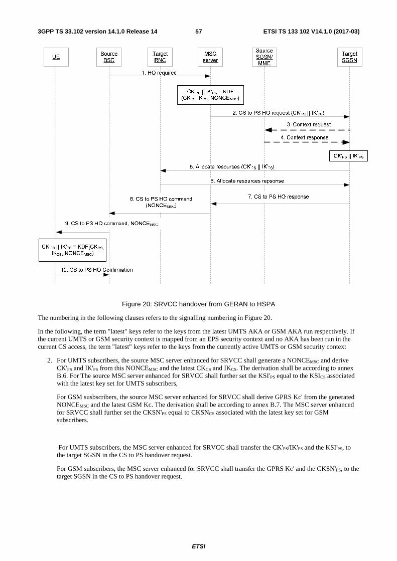
ETSI
ETSI TS 133 102 V14.1.0 (2017-03)573GPP TS 33.102 version 14.1.0 Release 14
UESourceBSC
Target RNC
MSC server
Source SGSN/MME
Target SGSN
1. HO required
CK'PS || IK'PS = KDF (CKCS, IKCS, NONCEMSC)
2. CS to PS HO request (CK'PS || IK'PS)
3. Context request
4. Context response
5. Allocate resources (CK'PS || IK'PS)
CK'PS || IK'PS
6. Allocate resources repsonse
7. CS to PS HO response8. CS to PS HO command (NONCEMSC)
9. CS to PS HO command, NONCEMSC
CK'PS || IK'PS = KDF(CKCS,
IKCS, NONCEMSC)
10. CS to PS HO Confirmation
Figure 20: SRVCC handover from GERAN to HSPA
The numbering in the following clauses refers to the signalling numbering in Figure 20.
In the following, the term "latest" keys refer to the keys from the latest UMTS AKA or GSM AKA run respectively. If the current UMTS or GSM security context is mapped from an EPS security context and no AKA has been run in the current CS access, the term "latest" keys refer to the keys from the currently active UMTS or GSM security context
2. For UMTS subscribers, the source MSC server enhanced for SRVCC shall generate a NONCEMSC and derive CK'PS and IK'PS from this NONCEMSC and the latest CKCS and IKCS. The derivation shall be according to annex B.6. For The source MSC server enhanced for SRVCC shall further set the KSI'PS equal to the KSICS associated with the latest key set for UMTS subscribers,
For GSM susbscribers, the source MSC server enhanced for SRVCC shall derive GPRS Kc' from the generated NONCEMSC and the latest GSM Kc. The derivation shall be according to annex B.7. The MSC server enhanced for SRVCC shall further set the CKSN'PS equal to CKSNCS associated with the latest key set for GSM subscribers.
For UMTS subscribers, the MSC server enhanced for SRVCC shall transfer the CK'PS/IK'PS and the KSI'PS, to the target SGSN in the CS to PS handover request.
For GSM subscribers, the MSC server enhanced for SRVCC shall transfer the GPRS Kc' and the CKSN'PS, to the target SGSN in the CS to PS handover request.
ETSI
ETSI TS 133 102 V14.1.0 (2017-03)583GPP TS 33.102 version 14.1.0 Release 14
NOTE 1: The MSC server enhanced for SRVCC does not include any authentication vectors in the CS to PS HO request, since this could result in that authentication vectors intended for use only in the CS domain would end up being used in a PS domain by accident.
NOTE 2: The MSC server enhanced for SRVCC does not include any UE security capability information in the CS to PS HO request, since the target SGSN either has this information available, or will retrieve the information from the old SGSN.
3 and 4. The target SGSN can request context information for the UE from an old SGSN. The target SGSN shall discard any CKPS, IKPS, GPRS Kc, CKSNPS and KSIPS received from an old SGSN. If the target SGSN received any authentication vectors from the old SGSN, the target SGSN shall process these authentication vectors according to clause 6.3.4 of the present document.
5. If the target SGSN received a GPRS Kc' and a CKSN'PS from the MSC server enchanced for SRVCC, then the target SGSN shall compute CK' PS and IK'PS from the GPRS Kc' using functions c4 and c5 of the present document. The target SGSN shall associate the CK' PS and IK'PS with KSI'PS, which shall be set equal to CKSN'PS received from the source MSC server enhanced for SRVCC.
SGSN shall send the CK'PS, IK'PS to the target RNC.
6a. The target RNC shall include the transparent container (RRCConnectionReconfiguration message) sent to the source BSC via the core network.
7. The target SGSN shall include the transparent container received from the target RNC in the CS to PS HO Response message sent to source MSC server enhanced for SRVCC.
8. Source MSC server enhanced for SRVCC shall include the transparent container and the NONCEMSC in the CS to PS HO command sent to the source BSC.
9. The source BSC shall include the transparent container and the NONCEMSC in the CS to PS HO command sent to the ME.
NOTE: This CS to PS HO command is optionally ciphered for GERAN.
For UMTS subscribers, the ME shall derive CK'PS and IK'PS. The derivation shall be done according to annex B.6, using the NONCEMSC received in the CS to PS HO command, the latest CKCS and IKCS. The ME shall set KSI'PS equal to KSICS and associate the newly derived keys with KSI'PS. If the USIM supports storage of GPRS Kc, the ME shall derive GPRS Kc' from CK'PS and IK'PS using the function c3 of the present specification. The ME shall associate the GPRS Kc' with CKSN'PS which shall be set equal to KSI’PS. The ME shall overwrite the stored parameters CKPS, IKPS , KSIPS , GPRS ciphering key Kc and GPRS CKSN PS if any, with the derived parameters CK’PS, IK’PS, KSI’PS, GPRS ciphering key Kc’ and GPRS CKSN’ PS in both ME and USIM when the SRVCC handover has been completed successfully..
For GSM subscribers, the ME shall derive GPRS Kc' according to annex B.7, using the NONCEMSC received in the CS to PS HO command and the latest GSM Kc. The ME shall set CKSN'PS equal to CKSNCS associated with the latest GSM security context and associate it with the GPRS Kc'. The ME shall in this case also derive CK'PS and IK'PS from the GPRS Kc' using the c4 and c5 functions of the present specification. The ME shall associate the CK'PS and IK'PS with KSI'PS which shall be set equal to CKSN'PS. The ME shall overwrite the stored parameters 64-bit GPRS ciphering key Kc and GPRS CKSNPS, if any, with the derived parameters GPRS ciphering key Kc’ and GPRS CKSN’PS in both ME and SIM when the SRVCC handover has been completed successfully.
10. .The ME sends the CS to PS handover confirmation message to the target RNC and the CK'PS and IK'PS shall become the active key set both in the ME and in the RNC.
If the SRVCC handover fails, the ME and the network shall discard all changes of state as specified above.
6.8.11 Handling of the START value in intersystem mobility cases
The START values (see clause 6.4.8) shall be kept in the volatile memory of the ME in the following cases:
- Intersystem idle mobility for CS Services – from UTRAN to GSM BSS;
ETSI
ETSI TS 133 102 V14.1.0 (2017-03)593GPP TS 33.102 version 14.1.0 Release 14
- Intersystem handover for CS Services – from UTRAN to GSM BSS;
- Intersystem change for PS Services – from UTRAN to GSM BSS;
- PS handover from Iu to Gb mode;
- SRVCC – from HSPA to UTRAN/GERAN;
NOTE: The handling of mobility from UTRAN to E-UTRAN is described in TS 33.401 [28]. Hence, also the corresponding handling of START is described there.
7 Void
8 Application security mechanisms
8.1 Void
8.2 Void
8.3 Mobile IP security The introduction of Mobile IP functionality for end users in 3G has no influence on the security architecture for 3G.
Mobile IP terminals may be equipped with security functionality independent of the 3G network access security in order to allow security functions outside the 3G network.
3G networks, supporting Mobile IP services, should support its inherent security functionality.
On the other hand, 3G network access security architecture can not be influenced or reduced by the Mobile IP option.
The Mobile IP security functionality must thus be separate from the 3G network access security and it is developed in an other forum, IETF.

ETSI
ETSI TS 133 102 V14.1.0 (2017-03)603GPP TS 33.102 version 14.1.0 Release 14
Annex A: Void
ETSI
ETSI TS 133 102 V14.1.0 (2017-03)613GPP TS 33.102 version 14.1.0 Release 14
Annex B (normative): Key derivation function
B.1 General The KDF is used to derive different keys. The different input key and input strings S used with the KDF is defined in the subclauses of this annex.The general description of the KDF and the encodings of its inputs are as defined by TS 33.220 [30] subclauses B.1 and B.2
B.2 FC value allocations The FC number space is controlled by TS 33.220 [30]. FC values allocated for this specification are in range of 0x30 – 0x3F.
B.3 Derivation of CK’CS|| IK’CS from CKPS||IKPS This input string is used for UMTS subscribers when there is a need to derive CK’CS|| IK’CS from CKPS||IKPS during mapping the security contexts from HSPA to UTRAN/GERAN. The Key is the concatenation of CKPS||IKPS (which are 128 bits each), and the output is CK’CS||IK’CS (which are 128 bits each).
- FC = 0x30
- P0 = NONCE
- L0 = length of NONCE (i.e. 0x00 0x10)
Further, the GSM Kc’ used in GERAN shall be derived from CK’CS||IK’CS using the key conversion function c3 defined in this specification.
B.4 Derivation of Kc’ from Kc for HSPA to UTRAN/GERAN SRVCC handover
This input string is used for GSM subscribers when there is a need to derive Kc’ from the 64-bit Kc during mapping the security contexts from HSPA to UTRAN/GERAN. The Key is the concatenation of Kc || Kc || Kc || Kc || (which are 64 bits each), and the output Kc’ is the 64 most significant bits of the KDF output.
- FC = 0x31
- P0 = NONCE
- L0 = length of NONCE (i.e. 0x00 0x10)
The Kc’ used in GERAN directly. When the access is over UTRAN, CK’CS||IK’CS shall be further derived from Kc’ using the key conversion functions c4 and c5 defined in this specification.
B.5 Derivation of Kc128 This input string is used when there is a need to derive Kc128 from CK and IK. The key Kc128 is used as input to the GSM A5 and GEA ciphering algorithms which requires 128-bit keys. Kc128 shall only be derived by the MS and the network when in UMTS security context. Kc128 shall not be derived by the MS or the network when in GSM security context. This implies that GSM A5 using Kc128 and GEA using Kc128 can only be selected by the network (see TS
ETSI
ETSI TS 133 102 V14.1.0 (2017-03)623GPP TS 33.102 version 14.1.0 Release 14
43.020 [36]) when the UE and network are in UMTS security context as there is otherwise no key which the ciphering algorithms can use.
- FC = 0x32
The Key input is the concatenation of CK and IK (i.e., CK || IK). No input parameters (Pi, Li) are used by this function. The KDF returns a 256-bit output, where the 128 most significant bits are identified with Kc128 .
B.6 Derivation of CK'PS || IK'PS from CKCS || IKCS This input string is used for UMTS subscribers when there is a need to derive CK'PS || IK'PS from CKCS || IKCS during mapping the security contexts from UTRAN/GERAN to HSPA. The input parameter Key is the concatenation of CKCS || IKCS (which are 128 bits each), and the output is CK'PS ||IK'PS (which are 128 bits each).
- FC = 0x33
- P0 = NONCEMSC
- L0 = length of NONCEMSC (i.e. 0x00 0x10)
Further, the GPRS Kc' used in GERAN shall be derived from CK'PS||IK'PS using the key conversion function c3 defined in this specification.
B.7 Derivation of Kc' from Kc for UTRAN/GERAN to HSPA SRVCC handover
This input string is used for GSM subscribers when there is a need to derive GPRS Kc' from the 64-bit Kc during mapping the security contexts from UTRAN/GERAN to HSPA. The input parameter Key is the concatenation of Kc || Kc || Kc || Kc || (which are 64 bits each), and the output Kc' is the 64 most significant bits of the KDF output.
- FC = 0x34
- P0 = NONCEMSC
- L0 = length of NONCEMSC (i.e. 0x00 0x10)
CK'PS || IK'PS shall be derived from GPRS Kc' using the key conversion functions c4 and c5 defined in this specification.

ETSI
ETSI TS 133 102 V14.1.0 (2017-03)633GPP TS 33.102 version 14.1.0 Release 14
Annex C (informative): Management of sequence numbers This annex is devoted to the management of sequence numbers for the authentication and key agreement protocol.
C.1 Generation of sequence numbers in the Authentication Centre
C.1.1 Sequence number generation schemes
C.1.1.1 General scheme
According to section 6.3 of this specification, authentication vectors are generated in the authentication centre (AuC) using sequence numbers. This section specifies how these sequence numbers are generated. Authentication vectors may be generated and sent by the AuC in batches. The sequence numbers for the authentication vectors in a batch are generated one after the other according to the process described below.
(1) In its binary representation, the sequence number consists of two concatenated parts SQN = SEQ || IND. IND is an index used in the array scheme described in C.1.2 and C.2.2. SEQ in its turn consists of two concatenated parts SEQ = SEQ1 || SEQ2. SEQ1 represents the most significant bits of SEQ, and SEQ2 represents the least significant bits of SEQ. IND represents the least significant bits of SQN.
(2) There is a counter SQNHE in the HE. SQN is stored by this counter. SQNHE is an individual counter, i.e. there is one per user. We have SQNHE = SEQHE || INDHE.
(3) There is a global counter, e.g. a clock giving universal time. For short we call the value of this global counter at any one time GLC. If GLC is taken from a clock it is computed mod p, where p = 2n and n is the length of GLC and of SEQ2 in bits.
(4) If GLC is taken from a clock then there is a number D > 0 such that the following holds: (i) the time interval between two consecutive increases of the clock (the clock unit) shall be chosen such that, for each user, at most D batches are generated at the AuC during any D clock units; (ii) the clock rate shall be significantly higher than the average rate at which batches are generated for any user; (iii) D << 2n.
(5) When the HE needs new sequence numbers SQN to create a new batch of authentication vectors, HE retrieves the (user-specific) value of SEQHE = SEQ1HE || SEQ2HE from the database. (i) If SEQ2HE < GLC < SEQ2HE + p – D + 1 then HE sets SEQ= SEQ1HE || GLC; (ii) if GLC ≤ SEQ2HE ≤ GLC+D - 1 or SEQ2HE + p – D + 1 ≤ GLC then HE sets SEQ = SEQHE +1; (iii) if GLC+D - 1 < SEQ2HE then HE sets SEQ = (SEQ1HE +1) || GLC. (iv) After the generation of the authentication vector has been completed SEQHE is reset to SEQ; (v) for the handling of IND see C.1.2.
NOTES
1. The clock unit and the value D have to be chosen with care so that condition (4)(i) is satisfied for every user at all times. Otherwise, user identity confidentiality may be compromised. When the parameters are chosen appropriately sequence numbers for a particular user do not reveal significant information about the user's identity. If authentication vectors for the CS and the PS domains are not separated by other means it is recommended to choose D >1 as requests from the two different domains may arrive completely independently.
ETSI
ETSI TS 133 102 V14.1.0 (2017-03)643GPP TS 33.102 version 14.1.0 Release 14
2. By setting the parameters in C.1.1.1 (1) to (5) in an appropriate way the general scheme specified in this subsection also includes the cases where either SEQ2 is void and SEQ = SEQ1 or else, SEQ1 is void and SEQ = SEQ2, as follows: (a) If SEQ2 is void the generation of sequence numbers is not time-based. We then formally set SEQ2 ≡ GLC ≡ 0 (identical to zero) and D = 1. Conditions (4)(i) to (iii) do not apply as there is no clock. Then (5)(ii) always holds, and SEQ is incremented by 1 at each request. For better readability, this case is separated out in C.1.1.2. (b) If SEQ1 is void then we set D = 1. Assuming a start condition SEQ2HE < GLC and the absence of failures in the AuC, the condition (5)(i) then always holds, and SEQ = GLC for each request, i.e. the generation of sequence numbers is entirely time-based. In order to also accommodate potential failures in the AuC for entirely time-based sequence number , the variant described in the following Annex C.1.1.3 may be used.
C.1.1.2 Generation of sequence numbers which are not time-based
The HE/AuC shall maintain a counter for each user, SQNHE = SEQHE || INDHE. To generate a fresh sequence number, SEQHE is incremented by 1, and the new counter value is used to generate the next authentication vector. For the handling of IND see C.1.2.
C.1.1.3 Time-based sequence number generation
In its binary representation, the sequence number consists of two concatenated parts SQN = SEQ || IND. The part SEQ is not divided into two parts. The global counter GLC is thus as long as SEQ. Instead of storing the individual counter SEQHE in the HE there is a value DIF stored in the HE which is individual for each user. The DIF value represents the current difference between generated SEQ values for that user and the GLC.
When the HE needs new sequence numbers SQN to create new authentication vectors, HE retrieves the (user-specific) value of DIF from the data base and calculates SEQ values as SEQ = GLC +DIF.
The DIF value may have to be updated in the HE only during the re-synchronization procedure. In this case the DIF value is set as DIF = SEQMS - GLC where SQNMS = SEQMS || INDMS is the value sent by USIM in the re-synchronization procedure.
C.1.2 Support for the array mechanism This subsection applies to all three schemes presented in subsection C.1.1.
Each time an authentication vector is generated, the AuC shall retrieve INDHE from storage and allocate a new index value IND for that vector according to suitable rules and include it in the appropriate part of SQN. The index value may range from 0 to a -1 where a is the size of the array.
An example value for the array size a is given in Annex C.3. The exact rules for index allocation are left unspecified. Guidelines are given in Annex C.3.4.
C.2 Handling of sequence numbers in the USIM This section assumes that sequence numbers are generated according to Annex C.1.
The USIM keeps track of an array of sequence number values it has accepted. Let SQNMS = SEQMS || INDMS denote the highest sequence number in the array.

ETSI
ETSI TS 133 102 V14.1.0 (2017-03)653GPP TS 33.102 version 14.1.0 Release 14
C.2.1 Protection against wrap around of counter in the USIM The USIM will not accept arbitrary jumps in sequence numbers, but only increases by a value of at most Δ.
Therefore (before applying the freshness conditions of Annex C.2.2) the received sequence number SQN shall only be accepted by the USIM if SEQ-SEQMS ≤ Δ. If SQN can not be accepted then the USIM shall generate a synchronisation failure message using SQNMS.
Conditions on the choice of Δ:
(1) Δ shall be sufficiently large so that the MS will not receive any sequence number with SEQ - SEQMS > Δ if the HE/AuC functions correctly.
(2) In order to prevent that SEQMS ever reaches the maximum batch number value SEQmax during the lifetime of the USIM the minimum number of steps SEQmax /Δ required to reach SEQmax shall be sufficiently large.
C.2.2 Verification of sequence number freshness in the USIM The USIM shall maintain an array of a previously accepted sequence number components: SEQMS (0), SEQMS (1),… SEQMS (a-1). The initial sequence number value in each array element shall be zero.
To verify that the received sequence number SQN is fresh, the USIM shall compare the received SQN with the sequence number in the array element indexed using the index value IND contained in SQN, i.e. with the array entry SEQMS (i) where i = IND is the index value.
(a) If SEQ > SEQMS (i) the USIM shall consider the sequence number to be guaranteed fresh and subsequently shall set SEQMS (i) to SEQ.
(b) If SEQ ≤ SEQMS (i) the USIM shall generate a synchronisation failure message using the highest previously accepted sequence number anywhere in the array, i.e. SQNMS.
The USIM shall also be able to put a limit L on the difference between SEQMS and a received sequence number component SEQ. If such a limit L is applied then, before verifying the above conditions (a) and (b), the sequence number shall only be accepted by the USIM if SEQMS - SEQ < L. If SQN can not be accepted then the USIM shall generate a synchronisation failure message using SQNMS.
C.2.3 Notes 1. Using the above array mechanism, it is not required that a previously visited VLR/SGSN deletes the unused
authentication vectors when a user de-registers from the serving network (super-charger concept). Retaining the authentication vectors for use when the user returns later may be more efficient as regards signalling when a user abroad switches a lot between two serving networks.
2. The array mechanism may also be used to avoid unjustified rejection of user authentication requests when authentication vectors in two VLR/SGSNs from different mobility management domains (circuit and packet) are used in an interleaving fashion.
3. When a VLR/SGSN uses fresh authentication vectors obtained during a previous visit of the user, the USIM can reject them although they have not been used before (because the array size a and the age limit L are finite). Rejection of a sequence number can therefore occur in normal operation, i.e., it is not necessarily caused by (malicious) replay or a database failure.
4. The mechanism presented in this section may allow the USIM to exploit knowledge about which authentication vectors were sent to the same VLR/SGSN. It may be assumed that authentication vectors sent to the same VLR/SGSN are always used in the correct order. Consequently, only one sequence number among those sent to the same VLR/SGSN has to be stored.
5. With the exception of SQNMS , the entries of the array need not be stored in full length if a limit L (age limit) on the difference between SEQMS and a received sequence number component SEQ is applied.
6. Condition (2) of Annex C.2.1 on Δ means that SQNMS can reach its maximum value only after a minimum of SEQmax /Δ successful authentications have taken place.
ETSI
ETSI TS 133 102 V14.1.0 (2017-03)663GPP TS 33.102 version 14.1.0 Release 14
7. There is a dependency of the choice of Δ and the size n of global counter GLC in Annex C.1.1.1: Δ shall be chosen larger than 2n.
C.3 Sequence number management profiles This section provides examples how values for the parameters defined in sections C.1 and C.2 may be chosen in a coherent way. These examples may serve as references when specifying practical sequence number management schemes. There is one example set of values for each of the three types of sequence number generation schemes:
- partly time-based corresponding to Annex C.1.1.1;
- not time-based corresponding to Annex C.1.1.2;
- entirely time-based corresponding to Annex C.1.1.3.
C.3.1 Profile 1: management of sequence numbers which are partly time-based
Generation of sequence numbers:
This follows the general scheme for the generation of sequence numbers specified in Annex C.1.1.1. The following parameter values are suggested for reference:
Time unit of the clock: 1 second
Length of IND in bits = 5.
Length of SEQ2 in bits = n : 24 This means that GLC will wrap around after p = 2n = 224 seconds = 194 days. This ensures that most users will have become active at least once during this period. This implies a length of SEQ1 in bits = 19.
Start conditions: Choose SQNHE = 0 for all users and GLC = 1.
Arrival rate temporarily higher than clock rate: Choose D = 216. D may be chosen quite large as long as the conditions in C.1.1.1 (4)(ii) and (iii) are satisfied. Choosing D = 216 = 65536 means that the condition in C.1.1.1 (4)(i) is satisfied unless more than 65536 requests for batches arrive within over 18 hours which is practically impossible.
Verification of sequence numbers in the USIM:
This follows the handling of sequence numbers in the USIM specified in Annex C.2.
Length of the array: a = 32. This satisfies the requirement in section 6.3.2 that the mechanism for the verification of sequence numbers shall ensure that a sequence number can still be accepted if it is among the last x sequence numbers generated.
Protection against wrap around: Choose Δ = 228. Choosing Δ = 228 means that an attack to force the counter in the USIM to wrap around would require at least SEQmax/Δ = 215 > 32.000 successful authentications (cf. note 6 of C.2.3). We have Δ > p, as required in note 7 of C.2.3.
Age limit for sequence numbers: The use of such a limit is optional. The choice of a value for the parameter L affects only the USIM. It has no impact on the choice of other parameters and it entirely up to the operator, depending on his security policy. Therefore no particular value is suggested here. To give an example: if the policy stipulates that authentication vectors older than x seconds shall be rejected then L has to be set to x as the time unit of the clock is 1 second.
User anonymity: the value of SQN does not allow to trace the user over longer periods. Therefore, there may be no need to conceal SQN by an anonymity key as specified in section 6.3.
ETSI
ETSI TS 133 102 V14.1.0 (2017-03)673GPP TS 33.102 version 14.1.0 Release 14
C.3.2 Profile 2: management of sequence numbers which are not time-based
Generation of sequence numbers:
This follows the scheme for the generation of sequence numbers specified in Annex C.1.1.2. The following parameter values are suggested for reference:
Length of IND in bits = 5.
Start conditions: SQNHE = 0 for all users.
Verification of sequence numbers in the USIM:
Length of the array: a = 32
Protection against wrap around: Choose Δ = 228. Choosing Δ = 228 means that an attack to force the counter in the USIM to wrap around would require at least SEQmax/Δ = 215 > 32.000 successful authentications (cf. note 6 of C.2.3). Note 7 of Annex C.2.3 does not apply.
Age limit for sequence numbers: There is no clock here. So, the “age” limit would be interpreted as the maximum allowed difference between SQNMS (see section 6.3) and the sequence number received. The use of such a limit is optional. The choice of a value for the parameter L affects only the USIM. It has no impact on the choice of other parameters and it entirely up to the operator, depending on his security policy. Therefore no particular value is suggested here.
User anonymity: the value of SQN may allow to trace the user over longer periods. If this is a concern then SQN has to be concealed by an anonymity key as specified in section 6.3.
C.3.3 Profile 3: management of sequence numbers which are entirely time-based
Generation of sequence numbers:
This follows the scheme for the generation of sequence numbers specified in Annex C.1.1.3. The following parameter values are suggested for reference:
Time unit of the clock: It has to be chosen in such a way that no two requests for a batch of authentication vectors arrive during one time unit. Value = 0.1 seconds
Length of IND in bits = 5.
Start conditions: GLC = 1 and, for all users, DIF = 0.
Verification of sequence numbers in the USIM:
This is done according to the handling of sequence numbers in the USIM specified in Annex C.2.
Length of the array: a = 32. This satisfies the requirement in section 6.3.2 that the mechanism for the verification of sequence numbers shall ensure that a sequence number can still be accepted if it is among the last x sequence numbers generated.
Protection against wrap around: Choose Δ = 228. Choosing Δ = 228 means that an attack to force the counter in the USIM to wrap around would require at least SEQmax/Δ = 215 > 32.000 successful authentications (cf. note 6 of C.2.3). Note 7 of C.2.3 does not apply.
Age limit for sequence numbers: The use of such a limit is optional. The choice of a value for the parameter L affects only the USIM. It has no impact on the choice of other parameters and it entirely up to the operator, depending on his security policy. Therefore no particular value is suggested here. To give an example: if the policy stipulates that authentication vectors older than x time units shall be rejected then L has to be set to x.
ETSI
ETSI TS 133 102 V14.1.0 (2017-03)683GPP TS 33.102 version 14.1.0 Release 14
User anonymity: the value of SQN does not allow to trace the user over longer periods. Therefore, there may be no need to conceal SQN by an anonymity key as specified in section 6.3.
C.3.4 Guidelines for the allocation of the index values in the array scheme
- General rule: index values IND used in the array scheme, according to Annex C.1.2, shall be allocated cyclically within its range 0, ... , a-1. This means that the index value IND used with the previously generated authentication vector is stored in SQNHE , and the next authentication vector shall use index value IND +1 mod a.
It may be useful to allow exceptions to this general rule when additional information is available. This includes:
- Authentication vectors distributed within the same batch shall have the same index value.
The Authentication Data Request MAP message contains information about the domain type (CS or PS) of the requesting serving node from which the request originates. It is recommended to use this information in the following way. Support for this use is, however, not required for an implementation to claim compliance to Annex C.
- Authentication vectors distributed to different service domains shall have different index values (i.e. separate ranges of index values are reserved for PS and CS operation).
In future releases there may be additional information about the requesting node identity. If this information is available it is recommended to use it in the following way:
- If the new request comes from the same serving node as the previous request, then the index value used for the new request shall be the same as was used for the previous request.
C.4 Guidelines for interoperability in a multi-vendor environment
The specification of a sequence number management scheme affects only the USIM and the AuC which are both under the control of one operator. Therefore, the specification of such a scheme is entirely at the discretion of an operator. Nevertheless, certain operators may not want to define a scheme of their own. Instead, they may want to rely on vendors implementing one of the schemes according to the profiles in C.3 or variants thereof. If these operators have multiple vendors for USIMs and/or AuCs, and the operators wish to move subscribers from the AuC of one vendor to that supplied by another one implementing a different scheme then this will work smoothly only when the following guidelines are adhered to by all the sequence number management schemes implemented in the operator’s domain.
- The array mechanism specified in clauses C.1.2 and C.2 is used in the USIM to verify SQNs. The length of the IND used by the USIM to index the array shall be not less than the length of the IND used by the AuC when allocating index values. However, it is recommended that the same IND length of 5 bits is used in USIMs and AuCs. This is the same IND length as proposed for all profiles in clause C.3.
- Relation to Annex F: if the AMF field is used to signal further parameters relevant to sequence number management (age limit L) then the formats of the AMF and its interpretation by the USIM must be the same for all implementations in the operator’s domain.
- Δ is larger than a specified minimum. This is necessary to accommodate schemes as in C.3.2 according to note 7 of C.2.3. We propose Δ ≥ 228.
- There are no requirements on the synchronicity of clocks in different AuCs for the time-based schemes. For the entirely time-based scheme, the following is recommended when moving users from one AuC to another one: The DIF value is updated in an appropriate manner when moving subscribers from an AuC to another AuC. More specifically, assume a user is moved from AuC1 to AuC2. If AuC1 is of profile 3 and AuC2 is of any profile then AuC1 sends GLC+DIF as SEQ_HE to AuC2. In the receiving end, if AuC2 is of profile 3 while AuC1 is of any profile then AuC2 sets DIF value for this user as DIF = SEQ_HE - GLC.

ETSI
ETSI TS 133 102 V14.1.0 (2017-03)693GPP TS 33.102 version 14.1.0 Release 14
Annex D: Void
ETSI
ETSI TS 133 102 V14.1.0 (2017-03)703GPP TS 33.102 version 14.1.0 Release 14
Annex E: Void
ETSI
ETSI TS 133 102 V14.1.0 (2017-03)713GPP TS 33.102 version 14.1.0 Release 14
Annex F (informative): Example uses of the proprietary part of the AMF
F.1 Support multiple authentication algorithms and keys A mechanism to support the use of multiple authentication and key agreement algorithms is useful for disaster recovery purposes. AMF may be used to indicate the algorithm and key used to generate a particular authentication vector.
The USIM keeps track of the authentication algorithm and key identifier and updates it according to the value received in an accepted network authentication token.
F.2 Changing sequence number verification parameters This mechanism is used in conjunction with the mechanism for the verification of sequence number freshness in the USIM described in C.2.2.
The USIM shall also be able to put a limit L on the difference between SEQMS (the highest SEQ accepted so far) and a received sequence number SEQ. A mechanism to change this parameter L dynamically is useful since the optimum for these parameters may change over time. AMF is used to indicate a new value of L to be used by the USIM.
F.3 Setting threshold values to restrict the lifetime of cipher and integrity keys
According to section 6.4.3, the USIM contains a mechanism to limit the amount of data that is protected by an access link key set. The AMF field may be used by the operator to set or adjust this limit in the USIM. For instance, there could be two threshold values and the AMF field instructs the USIM to switch between them.
The USIM keeps track of the limit to the key set life time and updates it according to the value received in an accepted network authentication token.
ETSI
ETSI TS 133 102 V14.1.0 (2017-03)723GPP TS 33.102 version 14.1.0 Release 14
Annex G (normative): Support of algorithm change features UEA2 and UIA2 have been developed as back up algorithms which should be installed in RNCs as soon as possible so that they are available for use in the hopefully unlikely event that the current algorithms UEA1 and UIA1 become compromised. Therefore it is reasonable to expect that operators will have been able to upgrade all their RNCs before the new algorithms need to be enabled. Consequently, algorithm change is only required at inter-network handover.
Based on the above assumptions, the following feature shall be supported:
- Encryption/integrity algorithm change at SRNC relocation with hard inter-network handover.
Based on the above assumptions, the following features do not have to be supported:
- Encryption/integrity algorithm change at "UE not involved" SRNC relocation for both the DCH and FACH cases.
NOTE: Only applies to intra-network case, since Iur is not supported between operators.
- Encryption/integrity algorithm change at SRNC relocation with hard intra-network handover.
ETSI
ETSI TS 133 102 V14.1.0 (2017-03)733GPP TS 33.102 version 14.1.0 Release 14
Annex H (normative): Usage of the AMF The 16 bits in the AMF are numbered from "0" to "15" where bit "0" is the most significant bit and bit "15" is the least significant bit (see subclause 3.4)
Bit "0" is called the "AMF separation bit". It is used for the purposes of EPS (Evolved Packet System) and is specified in
- TS 33.401 [28] for E-UTRAN access to EPS;
- TS 33.402 [29] for non-3GPP access to EPS.
Bits "1" to "7" are reserved for future standardization use. Bits "1" to "7" shall be set to 0 while not yet specified for a particular use.
Bits "8" to "15" can be used for proprietary purposes. See Annex F for examples usages.
ETSI
ETSI TS 133 102 V14.1.0 (2017-03)743GPP TS 33.102 version 14.1.0 Release 14
Annex I (normative): Security requirements for RNCs in exposed locations
I.1 General RNCs may be deployed at exposed locations where they run a higher risk of physical attack than RNCs in physically protected parts of the operator domain. For such deployments, RNCs adhering to the security requirements in this Annex should be used. RNCs in other deployments are not required to adhere to these requirements.
RNCs may be found in exposed locations e.g. when RNC and NB are co-located in one node (collapsed RNC / NBs).
NOTE: These security requirements have been modelled after those in clause 5.3 of TS 33.401 [28]. These requirements apply in addition to the security requirements stated for Iu and Iur interfaces in Annex D of TS 33.210 [39].
I.2 Requirements for RNCs in exposed locations
I.2.1 Requirements for setup and configuration Setting up and configuring RNCs in exposed locations shall be authenticated and authorized so that attackers shall not be able to modify the settings and software configurations of the RNCs in exposed locations via local or remote access.
1. The support of security associations is required between the 3G core network and the RNC in an exposed location and between adjacent RNCs in exposed locations. These security association establishments shall be mutually authenticated and used for user and control plane communication between the entities. The security associations shall be realized according to Annex I.3 of the present document.
2. Communication between the O&M systems and the RNC in an exposed location shall be confidentiality, integrity and replay protected from unauthorized parties. The support of security associations is required between the RNC in an exposed location and an entity in the 3G core network or in an O&M domain trusted by the operator. These security association establishments shall be mutually authenticated.
3. The RNC in an exposed location shall ensure that software/data change attempts are authorized.
4. The RNC in an exposed location shall use authorized data/software.
5. Sensitive parts of the boot-up process shall be executed with the help of the secure environment.
6. Confidentiality of software transfer towards the RNC in an exposed location shall be ensured.
7. Integrity protection of software transfer towards the RNC in an exposed location shall be ensured.
I.2.2 Requirements for key management inside RNCs in exposed locations
The 3G core network provides subscriber specific session keys for the RNCs in exposed locations. RNCs in exposed locations also hold long term keys used for the purpose of authentication and security association setup on the backhaul link. Protecting all these keys is important.
1. Keys stored inside an RNC in an exposed location shall never leave a secure environment within the RNC in an exposed location except when done in accordance with the present document or other 3GPP specifications.
ETSI
ETSI TS 133 102 V14.1.0 (2017-03)753GPP TS 33.102 version 14.1.0 Release 14
I.2.3 Requirements for handling user plane data An RNC in an exposed location has to cipher and decipher user plane packets between the Uu reference point and the Iu reference point and to handle integrity protection for user plane packets for the Iu reference point.
1. User plane data ciphering/deciphering and integrity handling shall take place inside the secure environment where the related keys are stored.
2. The transport of user data over Iu shall be integrity, confidentiality-, and replay-protected from unauthorized parties. If this is to be accomplished by cryptographic means, Annex I.3 shall be applied.
NOTE: Protection for user data extends between the UE and the serving RNC, hence no separate requirement for the protection of user plane data transferred between a serving RNC and a potentially present drift RNC (cf. TS 25.420 [38]) is needed.
I.2.4 Requirements for handling control plane data An RNC in an exposed location has to provide confidentiality and integrity protection for control plane packets on the Iu and Iur reference points.
1. Control plane data ciphering/deciphering and integrity handling shall take place inside the secure environment where the related keys are stored.
2. The transport of control plane data over Iu and Iur shall be integrity-, confidentiality- and replay-protected from unauthorized parties. If this is to be accomplished by cryptographic means, Annex I.3 shall be applied.
NOTE: Protection for signalling data that is sent from or to the UE extends between the UE and the serving RNC, cf. the NOTE in Annex I.2.3. This protection does not, however, cover the signalling data exchanged between RNCs over Iur; hence a separate requirement is needed for Iur.
I.2.5 Requirements for secure environment The secure environment is logically defined within the RNC in an exposed location and is a composition of functions for the support of sensitive operations.
1. The secure environment shall support secure storage of sensitive data, e.g. long term cryptographic secrets and vital configuration data.
2. The secure environment shall support the execution of sensitive functions, e.g. en-/decryption of user data and the basic steps within protocols which use long term secrets (e.g. in authentication protocols).
3. Sensitive data used within the secure environment shall not be exposed to external entities.
4. The secure environment shall support the execution of sensitive parts of the boot process.
5. The secure environment's integrity shall be assured.
6. Only authorised access shall be granted to the secure environment, i.e. to data stored and used within, and to functions executed within.
I.3 Security mechanisms for interfaces with RNCs in exposed locations
In order to protect the Iu and Iur interfaces as required by Annexes X.2.3 and X.2.4, it is required to implement IPsec ESP as specified and profiled by TS 33.210 [39], with confidentiality, integrity and replay protection.
NOTE 1: In certain deployments IPsec security mechanisms may not be usable on the interfaces of the RNC in exposed locations. In such cases it is an operator decision to either ensure the interface security by other means, or to change the interface transport mechanisms to allow the application of IPsec security mechanisms.
ETSI
ETSI TS 133 102 V14.1.0 (2017-03)763GPP TS 33.102 version 14.1.0 Release 14
IKEv2 with certificates based authentication shall be implemented. The certificates shall be implemented according to the profile described by TS 33.310 [40]. IKEv2 shall be implemented conforming to the IKEv2 profile described in TS 33.310 [40].
For Iu and Iur, tunnel mode IPsec is mandatory to implement. On the core network side a SEG may be used to terminate the IPsec tunnel.
Transport mode IPsec is optional for implementation on Iu and Iur.
NOTE 2: Transport mode can be used for reducing the protocol overhead added by IPsec.
NOTE 3: The IPsec security associations may also apply to IP packets carrying management information.
If the sender of IPsec traffic uses DiffServ Code Points (DSCPs) to distinguish different QoS classes, either by copying DSCP from the inner IP header or directly setting the encapsulating IP header’s DSCP, the resulting traffic may be reordered to the point where the receiving node’s anti-replay check discards the packet. If different DSCPs are used on the encapsulating IP header, then to avoid packet discard under one IKE SA and with the same set of traffic selectors, distinct child-SAs should be established for each of the traffic classes (using the DSCPs as classifiers) as is specified in RFC 4301 [41].

ETSI
ETSI TS 133 102 V14.1.0 (2017-03)773GPP TS 33.102 version 14.1.0 Release 14
Annex J (informative): Change history
Change history TSG SA
# Version CR Tdoc SA New
Version Subject/Comment
SP-03 2.0.0 - - 3.0.0 Approved at SA#3 and placed under TSG SA Change Control SP-11 3.7.0 135 SP-010131 3.8.0 RES has to be a multiple of 8 bits SP-11 3.7.0 136 SP-010131 3.8.0 Add bit ordering convention SP-11 3.7.0 137 SP-010131 3.8.0 Timing of security mode procedure SP-11 3.7.0 140 SP-010131
3.8.0 Correction to the handling of re-transmitted authentication request messages on the ME
SP-11 3.7.0 141 SP-010131 3.8.0 Optional Support for USIM-ME interface for GSM-Only ME SP-11 3.7.0 142 SP-010131 3.8.0 Definition corrections SP-11 3.7.0 143 SP-010131
3.8.0 GSM ciphering capability Handling in Security Mode set up procedure
SP-11 3.8.0 138 SP-010132 4.0.0 Add requesting node type to authentication data request SP-11 3.8.0 139 SP-010132 4.0.0 Provide additional information to HE to detect fraud conditions. SP-12 4.0.0 145 SP-010313 4.1.0 Correction to periodic local authentication SP-12 4.0.0 147 SP-010314 4.1.0 Correction to COUNT-C description SP-12 4.0.0 150 SP-010316 4.1.0 Calculation and Wrap-around of START value SP-12 4.0.0 152 SP-010317
4.1.0 Correction to integrity protection when the user is attached to a UTRAN with R99+ ME with a SIM inserted
SP-12 4.0.0 154 SP-010319 4.1.0 THRESHOLD Check at RRC connection establishment SP-13 4.1.0 155r1 SP-010492
4.2.0 Removing the list of access type codes from authentication failure report
SP-14 4.2.0 157 SP-010608 4.3.0 Annex F.2 (changing list parameters) modification SP-14 4.2.0 159 SP-010609 4.3.0 Sequence Number Management Corrections SP-14 4.2.0 161 SP-010610 4.3.0 SQNMS retrieval in AuC during resynchronisation SP-16 4.3.0 166 SP-020340 4.4.0 Optional use of Access Link Data Confidentiality SP-16 4.3.0 170r1 SP-020342
4.4.0 Encryption/Integrity algorithms ordered by preference in Security Mode command
SP-16 4.3.0 172 SP-020343 4.4.0 Correction of (U)SIM toolkit security reference SP-16 4.4.0 174r1 SP-020385 5.0.0 Clarification of sequence number management (Rel-5 created) SP-18 5.0.0 175 SP-020700 5.1.0 USIM support in GERAN only terminals SP-18 5.0.0 178 SP-020790 5.1.0 Correction to the START formula SP-20 5.1.0 179 SP-030224 5.2.0 Handling of START values stored on a ME for use with a SIM SP-21 5.2.0 181 SP-030476
5.3.0 IMEISV retrieval before completion of security mode setup procedure
SP-21 5.2.0 182 SP-030476 5.3.0
Mitigation against a man-in-the-middle attack associated with early UE handling
SP-21 5.2.0 180 SP-030475 6.0.0 Clarification on the usage of the c3 conversion function SP-24 6.0.0 185 SP-040370 6.1.0 Handling of key sets at inter-system change SP-24 6.0.0 186 SP-040369 6.1.0 Clarification on Authentication re-attempt parameter SP-25 6.1.0 188 SP-040627 6.2.0 Correction to mis-implementation of CR175: Rel4- definition SP-26 6.2.0 189 SP-040852 6.3.0 Correction of Abbreviation for USIM SP-26 6.2.0 190R1 SP-040852 6.3.0 Correction of TMUI to TMSI in a figure SP-26 6.2.0 191R3 SP-040852 6.3.0 Support of algorithms in UEs and RNCs SP-29 6.3.0 0194 SP-050542 6.4.0 Keystatus sent by CN node in Security Mode Command SP-29 6.3.0 0195 SP-050549 6.4.0 Incorrect usage of COUNT-I in security mode set-up procedure SP-30 6.4.0 0196 SP-050771 6.5.0 Clarify key set handling for PS handover SP-30 6.4.0 0198 SP-050761
6.5.0 Correction on Keystatus sent by CN node in Security Mode Command
SP-30 6.5.0 - SP-050654 7.0.0 Raised to Rel-7 to allow reference by TISPAN SP-34 7.0.0 0199R1 SP-060806 7.1.0 Support of algorithm change features SP-34 7.0.0 0200R1 SP-060806 7.1.0 Support of UIA2, UEA2 algorithms SP-40 8.0.0 0203R2 SP-080267 8.0.0 Reserve 8 AMF bits for standardization purposes SP-42 8.0.0 0204 SP-080743 8.1.0 Correction on the storage of keys on the USIM SP-43 8.1.0 0206 SP-090138 8.2.0 Update of definition of UMTS security context SP-43 8.1.0 0205 SP-090137 8.2.0 Generation and use of the mapped security context in HSPA SRVCC SP-43 8.1.0 0205 SP-090136 8.2.0 Add reference to ciphering indicator feature specification SP-44 8.2.0 0229 SP-090278 8.3.0 Correction of security procedure of HSPA SRVCC SP-45 8.3.0 0207 SP-090560 8.4.0 Reformulation of security procedure of HSPA SRVCC SP-45 8.4.0 0208 SP-090635 9.0.0 Derivation of Kc128 with UMTS AKA SP-46 9.0.0 0210 SP-090861
9.1.0 Mandating integrity protection of reject messages that cause CSG list to be modified
SP-46 9.0.0 0211 SP-090823 9.1.0 Replacing KDF definition with a reference SP-46 9.0.0 0213 SP-090824 9.1.0 Security considerations for emergency sessions in HSPA SRVCC
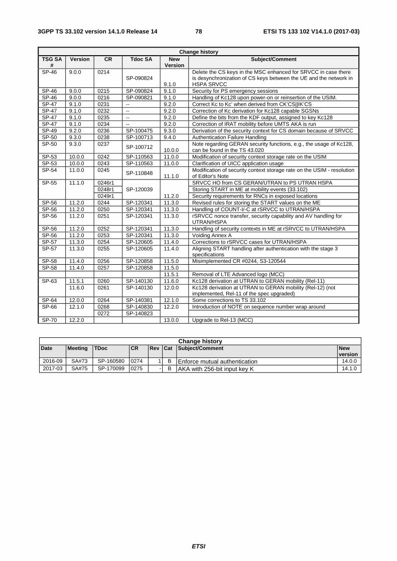
ETSI
ETSI TS 133 102 V14.1.0 (2017-03)783GPP TS 33.102 version 14.1.0 Release 14
Change history TSG SA
# Version CR Tdoc SA New
Version Subject/Comment
SP-46 9.0.0 0214 SP-090824
9.1.0
Delete the CS keys in the MSC enhanced for SRVCC in case there is desynchronization of CS keys between the UE and the network in HSPA SRVCC
SP-46 9.0.0 0215 SP-090824 9.1.0 Security for PS emergency sessions SP-46 9.0.0 0216 SP-090821 9.1.0 Handling of Kc128 upon power-on or reinsertion of the USIM. SP-47 9.1.0 0231 -- 9.2.0 Correct Kc to Kc’ when derived from CK’CS||IK’CS SP-47 9.1.0 0232 -- 9.2.0 Correction of Kc derivation for Kc128 capable SGSNs SP-47 9.1.0 0235 -- 9.2.0 Define the bits from the KDF output, assigned to key Kc128 SP-47 9.1.0 0234 -- 9.2.0 Correction of IRAT mobility before UMTS AKA is run SP-49 9.2.0 0236 SP-100475 9.3.0 Derivation of the security context for CS domain because of SRVCC SP-50 9.3.0 0238 SP-100713 9.4.0 Authentication Failure Handling SP-50 9.3.0 0237 SP-100712
10.0.0 Note regarding GERAN security functions, e.g., the usage of Kc128, can be found in the TS 43.020
SP-53 10.0.0 0242 SP-110563 11.0.0 Modification of security context storage rate on the USIM SP-53 10.0.0 0243 SP-110563 11.0.0 Clarification of UICC application usage SP-54 11.0.0 0245 SP-110848 11.1.0
Modification of security context storage rate on the USIM - resolution of Editor's Note
SP-55 11.1.0 0246r1 SP-120039
11.2.0
SRVCC HO from CS GERAN/UTRAN to PS UTRAN HSPA 0248r1 Storing START in ME at mobility events (33.102) 0249r1 Security requirements for RNCs in exposed locations
SP-56 11.2.0 0244 SP-120341 11.3.0 Revised rules for storing the START values on the ME SP-56 11.2.0 0250 SP-120341 11.3.0 Handling of COUNT-I/-C at rSRVCC to UTRAN/HSPA SP-56 11.2.0 0251 SP-120341 11.3.0 rSRVCC nonce transfer, security capability and AV handling for
UTRAN/HSPA SP-56 11.2.0 0252 SP-120341 11.3.0 Handling of security contexts in ME at rSRVCC to UTRAN/HSPA SP-56 11.2.0 0253 SP-120341 11.3.0 Voiding Annex A SP-57 11.3.0 0254 SP-120605 11.4.0 Corrections to rSRVCC cases for UTRAN/HSPA SP-57 11.3.0 0255 SP-120605 11.4.0 Aligning START handling after authentication with the stage 3
specifications SP-58 11.4.0 0256 SP-120858 11.5.0 Misimplemented CR #0244, S3-120544 SP-58 11.4.0 0257 SP-120858 11.5.0 11.5.1 Removal of LTE Advanced logo (MCC) SP-63 11.5.1 0260 SP-140130 11.6.0 Kc128 derivation at UTRAN to GERAN mobility (Rel-11)
11.6.0 0261 SP-140130 12.0.0 Kc128 derivation at UTRAN to GERAN mobility (Rel-12) (not implemented, Rel-11 of the spec upgraded)
SP-64 12.0.0 0264 SP-140381 12.1.0 Some corrections to TS 33.102 SP-66 12.1.0 0268 SP-140830 12.2.0 Introduction of NOTE on sequence number wrap around
0272 SP-140823 SP-70 12.2.0 13.0.0 Upgrade to Rel-13 (MCC)
Change history Date Meeting TDoc CR Rev Cat Subject/Comment New
version 2016-09 SA#73 SP-160580 0274 1 B Enforce mutual authentication 14.0.0 2017-03 SA#75 SP-170099 0275 - B AKA with 256-bit input key K 14.1.0
ETSI
ETSI TS 133 102 V14.1.0 (2017-03)793GPP TS 33.102 version 14.1.0 Release 14
History
Document history
V14.1.0 March 2017 Publication