huawei gsm handover algorithm i
DESCRIPTION
GSM HO AlgoTRANSCRIPT

Huawei Confidential. All Rights Reserved
OMF010002 Handover
ISSUE 2.0

2 Internal Use
Handover is key technology of Mobile
communication system and make
continued conversation possible.
Handover algorithm in Huawei product
is flexible and powerful
3 Internal Use
ObjectivesObjectives
Upon completion this course, you will be able to:
Understand the type of handover.
Master handover judgment flow
Configure handover data
Master handover signaling flow
4 Internal Use
Chapter 1 Chapter 1 Introduction of HandoverIntroduction of Handover
Chapter 2 HO Algorithm process
Chapter 3 HO Data Configuration
Chapter 4 HO Signaling process
5 Internal Use
Purposes of HOPurposes of HO
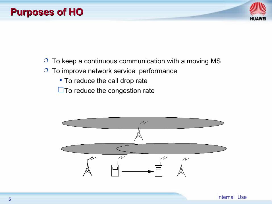
To keep a continuous communication with a moving MS To improve network service performanceTo reduce the call drop rateTo reduce the congestion rate
6 Internal Use
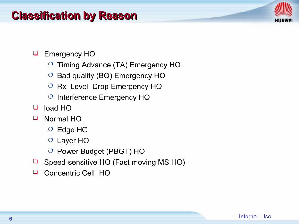
Emergency HO Timing Advance (TA) Emergency HO Bad quality (BQ) Emergency HO Rx_Level_Drop Emergency HO Interference Emergency HO
load HO Normal HO
Edge HO Layer HO Power Budget (PBGT) HO
Speed-sensitive HO (Fast moving MS HO) Concentric Cell HO
Classification by ReasonClassification by ReasonClassification by ReasonClassification by Reason
7 Internal Use
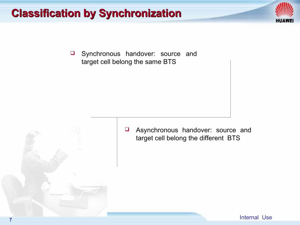
Classification by SynchronizationClassification by Synchronization
Synchronous handover: source and target cell belong the same BTS
Asynchronous handover: source and target cell belong the different BTS
8 Internal Use
Chapter 1 Introduction of Handover
Chapter 2 Chapter 2 HO Algorithm processHO Algorithm process
Chapter 3 HO Data Configuration
Chapter 4 HO Signaling process
9 Internal Use
Chapter 2 Chapter 2 HO Algorithm processHO Algorithm process
Section 1 General HO process
Section 2 Measurement report preprocessing
Section 3 Penalty processing
Section 4 Basic ranking and Secondary ranking
Section 5 Condition of handover
10 Internal Use
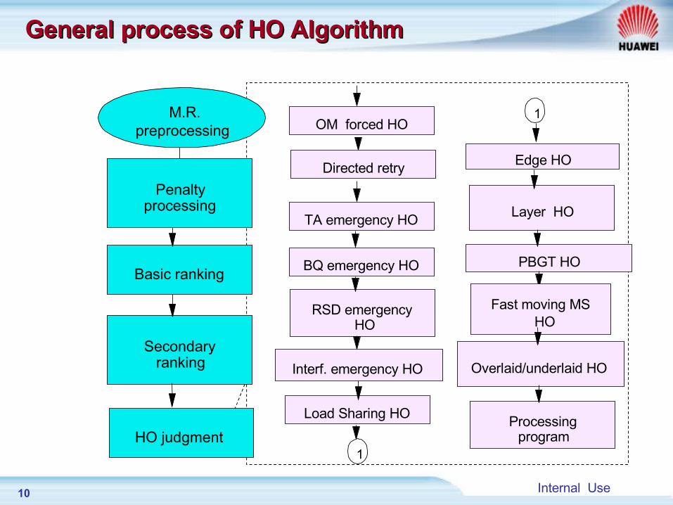
General process of HO AlgorithmGeneral process of HO Algorithm
M.R.preprocessing
Penalty processing
Basic ranking
Secondary ranking
HO judgment
TA emergency HO
BQ emergency HO
RSD emergency HO
Interf. emergency HO
Load Sharing HO
Edge HO
Layer HO
PBGT HO
Processing program
OM forced HO
Directed retry
Overlaid/underlaid HO
Fast moving MS HO
1
1
11 Internal Use
Chapter 2 Chapter 2 HO Algorithm processHO Algorithm process
Section 1 General HO process
Section 2 Measurement report preprocessing
Section 3 Penalty processing
Section 4 Basic ranking and Secondary ranking
Section 5 Condition of handover
12 Internal Use
Measurement ReportMeasurement Report
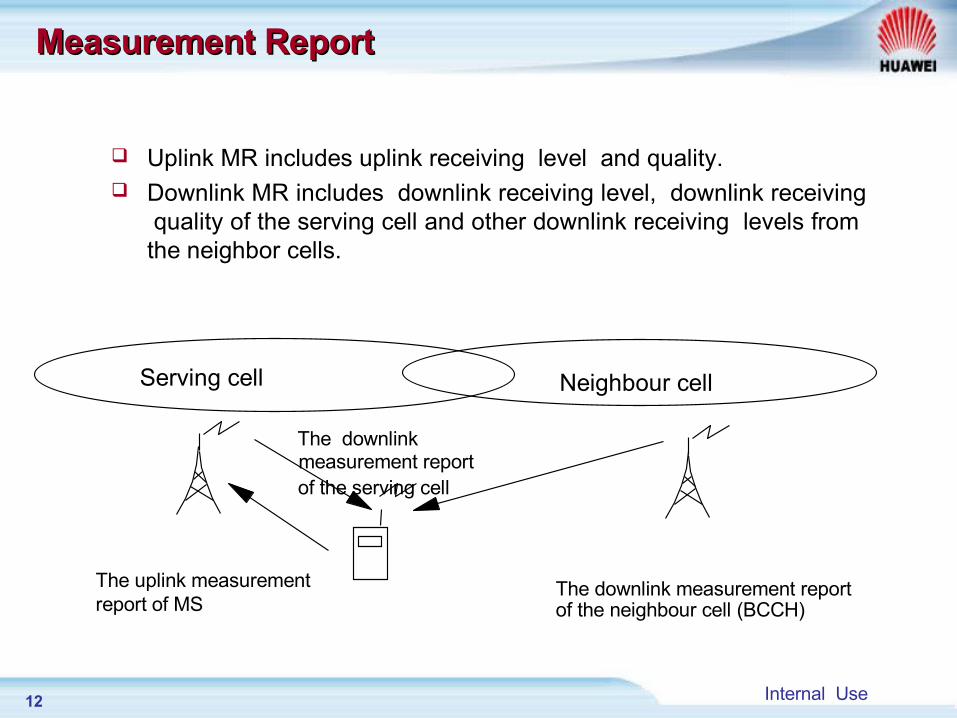
Uplink MR includes uplink receiving level and quality. Downlink MR includes downlink receiving level, downlink receiving
quality of the serving cell and other downlink receiving levels from the neighbor cells.
Serving cell Neighbour cell
The downlink measurement report of the serving cell
The uplink measurement report of MS
The downlink measurement reportof the neighbour cell (BCCH)
13 Internal Use
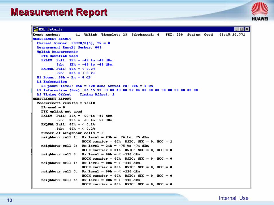
Measurement ReportMeasurement Report
14 Internal Use
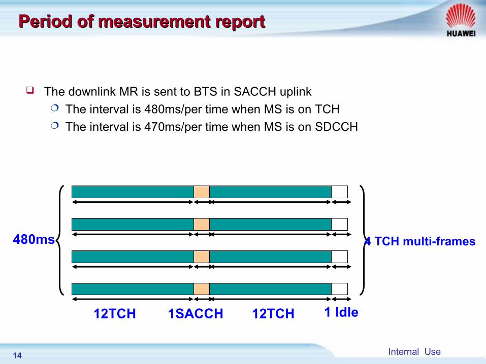
Period of measurement report Period of measurement report
The downlink MR is sent to BTS in SACCH uplink The interval is 480ms/per time when MS is on TCH The interval is 470ms/per time when MS is on SDCCH
12TCH 12TCH1SACCH 1 Idle
480ms 4 TCH multi-frames
15 Internal Use
MR interpolation MR interpolation
Every time BSC receives a measurement report, there will be an update to the basic rank of the cells.
BTS may fail to receive the measurement report from MS. Before the rank-update, BSC needs to recover the lost measurement reports according to Filter Table. If the lost MR amount is within the allowed range, then recovers the lost MR according to the algorithm.
16 Internal Use
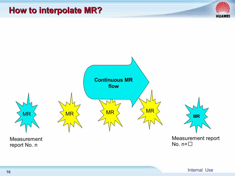
MR MR MR MR MR
Measurement report No. n
Measurement report No. n+
Continuous MR flow
How to interpolate MR?How to interpolate MR?
17 Internal Use
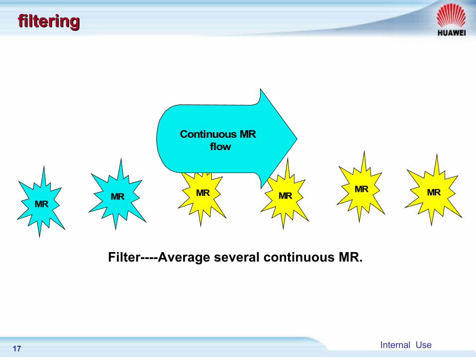
Filter----Average several continuous MR.
MR MR MR MR MR MR
Continuous MR flow
filteringfiltering
18 Internal Use
Chapter 2 Chapter 2 HO Algorithm processHO Algorithm process
Section 1 General HO process
Section 2 Measurement report preprocessing
Section 3 Penalty processing
Section 4 Basic ranking and Secondary ranking
Section 5 Condition of handover
19 Internal Use
Penalty ProcessingPenalty Processing
There are altogether four types of penalty process (second step of HO algorithm process ) Penalty on the target cell when a HO fails. Penalty on the original serving cell when an emergency HO
( base on BQ and TA ) is performed. Penalty on other high priority layer cells after a fast moving HO
is performed. A new HO attempt is prohibited within the penalty time after an
overlaid/underlaid HO fails.
20 Internal Use
BTS
HO failure
BSC
Cell A
Cell B
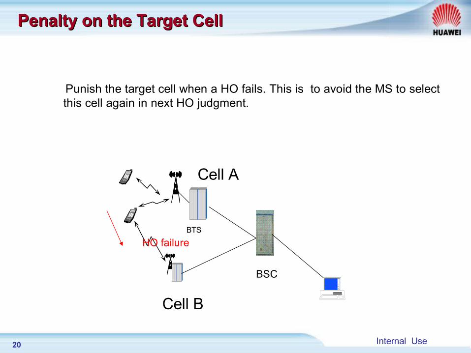
Penalty on the Target Cell Penalty on the Target Cell
Punish the target cell when a HO fails. This is to avoid the MS to select this cell again in next HO judgment.
21 Internal Use
BTS
BQ& TA HO
BSC
Cell A
Cell B
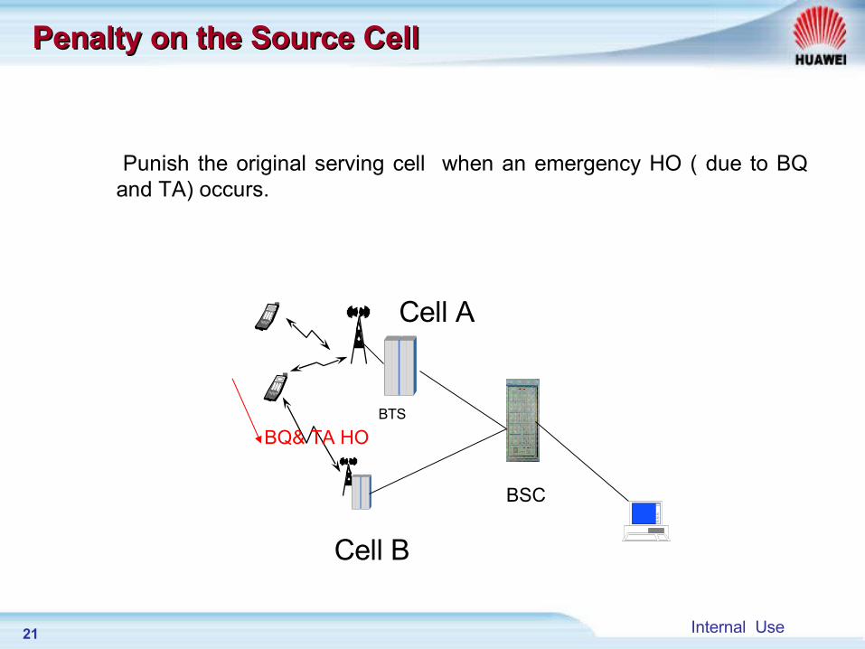
Penalty on the Source CellPenalty on the Source Cell
Punish the original serving cell when an emergency HO ( due to BQ and TA) occurs.
22 Internal Use
Back? No way!Back? No way!
Umbrella
Micro cell
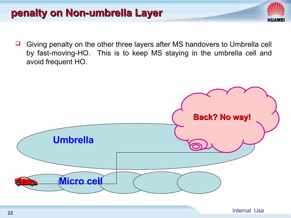
penalty on Non-umbrella Layer penalty on Non-umbrella Layer
Giving penalty on the other three layers after MS handovers to Umbrella cell by fast-moving-HO. This is to keep MS staying in the umbrella cell and avoid frequent HO.
23 Internal Use
Underlaid
Overlaid Do not attempt
again after a failed HO!
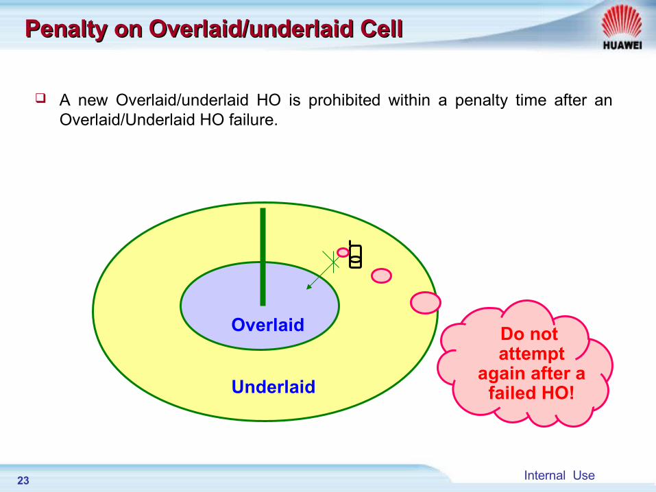
Penalty on Overlaid/underlaid CellPenalty on Overlaid/underlaid Cell
A new Overlaid/underlaid HO is prohibited within a penalty time after an Overlaid/Underlaid HO failure.
24 Internal Use
Chapter 2 Chapter 2 HO Algorithm processHO Algorithm process
Section 1 General HO process
Section 2 Measurement report preprocessing
Section 3 Penalty processing
Section 4 Basic ranking and Secondary ranking
Section 5 Condition of handover
25 Internal Use
Procedure of RankingProcedure of Ranking
Basic ranking and secondary ranking of cells are major parts of the HO judgment. Ranking is made through 16bits-algorithm. The serving cell and the neighbor cells will be listed in a cell list according to their 16bits value. The ranking processes include: M rule K rule 16bits ranking
26 Internal Use
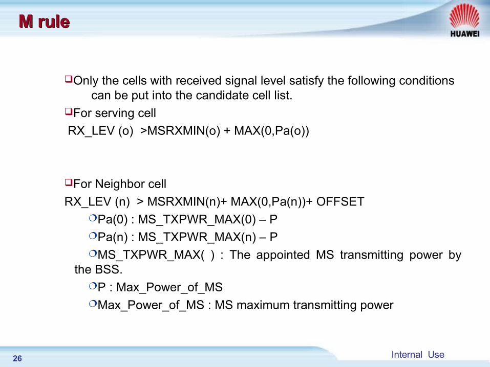
Only the cells with received signal level satisfy the following conditions can be put into the candidate cell list.
For serving cell
RX_LEV (o) >MSRXMIN(o) + MAX(0,Pa(o))
For Neighbor cell
RX_LEV (n) > MSRXMIN(n)+ MAX(0,Pa(n))+ OFFSETPa(0) : MS_TXPWR_MAX(0) – PPa(n) : MS_TXPWR_MAX(n) – PMS_TXPWR_MAX( ) : The appointed MS transmitting power by
the BSS.P : Max_Power_of_MSMax_Power_of_MS : MS maximum transmitting power
M rule M rule
27 Internal Use
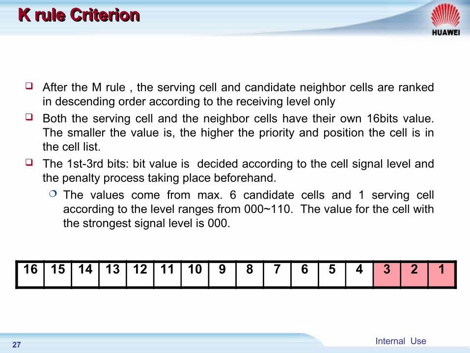
After the M rule , the serving cell and candidate neighbor cells are ranked in descending order according to the receiving level only
Both the serving cell and the neighbor cells have their own 16bits value. The smaller the value is, the higher the priority and position the cell is in the cell list.
The 1st-3rd bits: bit value is decided according to the cell signal level and the penalty process taking place beforehand. The values come from max. 6 candidate cells and 1 serving cell
according to the level ranges from 000~110. The value for the cell with the strongest signal level is 000.
K rule CriterionK rule CriterionK rule CriterionK rule Criterion
16 15 14 13 12 11 10 9 8 7 6 5 4 3 2 1
28 Internal Use
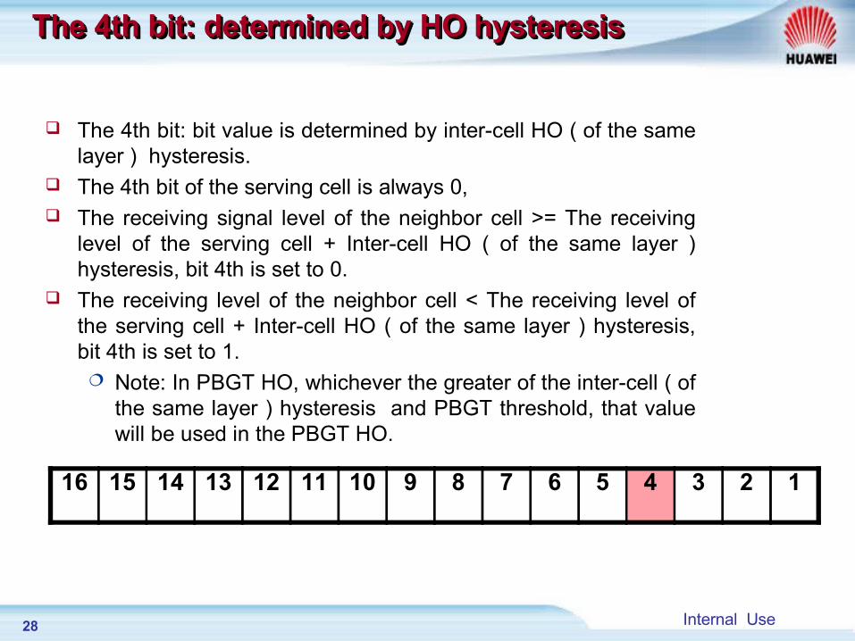
The 4th bit: bit value is determined by inter-cell HO ( of the same layer ) hysteresis.
The 4th bit of the serving cell is always 0, The receiving signal level of the neighbor cell >= The receiving
level of the serving cell + Inter-cell HO ( of the same layer ) hysteresis, bit 4th is set to 0.
The receiving level of the neighbor cell < The receiving level of the serving cell + Inter-cell HO ( of the same layer ) hysteresis, bit 4th is set to 1. Note: In PBGT HO, whichever the greater of the inter-cell ( of
the same layer ) hysteresis and PBGT threshold, that value will be used in the PBGT HO.
The 4th bit: determined by HO hysteresisThe 4th bit: determined by HO hysteresisThe 4th bit: determined by HO hysteresisThe 4th bit: determined by HO hysteresis
16 15 14 13 12 11 10 9 8 7 6 5 4 3 2 1
29 Internal Use
The 5th—10th bit: determined by Layer The 5th—10th bit: determined by Layer
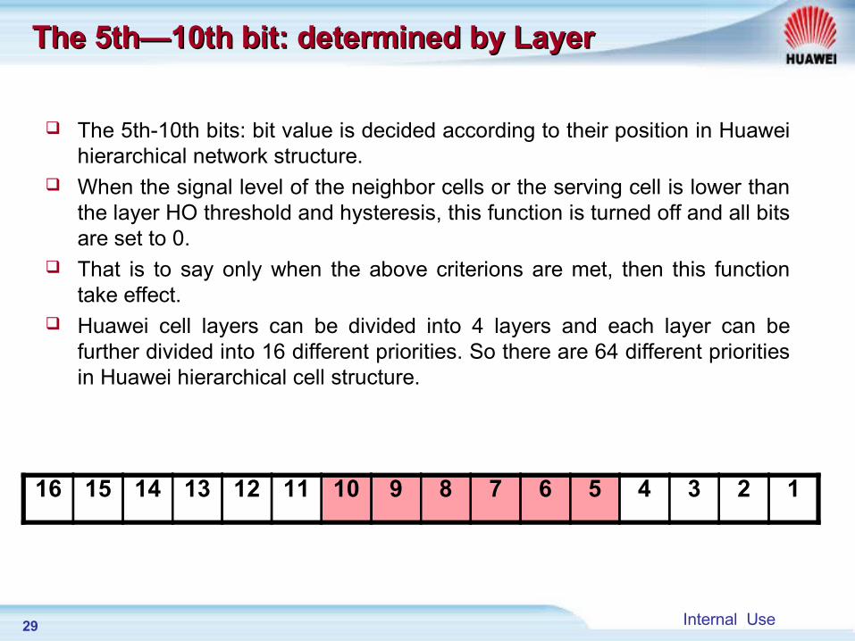
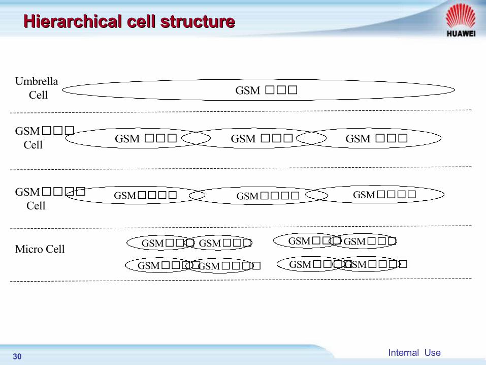
The 5th-10th bits: bit value is decided according to their position in Huawei hierarchical network structure.
When the signal level of the neighbor cells or the serving cell is lower than the layer HO threshold and hysteresis, this function is turned off and all bits are set to 0.
That is to say only when the above criterions are met, then this function take effect.
Huawei cell layers can be divided into 4 layers and each layer can be further divided into 16 different priorities. So there are 64 different priorities in Huawei hierarchical cell structure.
16 15 14 13 12 11 10 9 8 7 6 5 4 3 2 1
30 Internal Use
GSM Cell
Micro Cell
Umbrella Cell GSM
GSM GSMGSM
GSM GSM GSM
GSMGSM
GSMGSM
GSMGSM
GSMGSM
GSM Cell
Hierarchical cell structureHierarchical cell structure
31 Internal Use
The 11th bit: determined by The 11th bit: determined by loadload
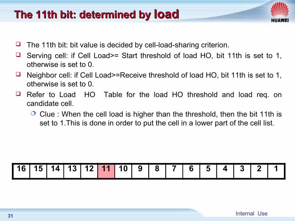
The 11th bit: bit value is decided by cell-load-sharing criterion. Serving cell: if Cell Load>= Start threshold of load HO, bit 11th is set to 1,
otherwise is set to 0. Neighbor cell: if Cell Load>=Receive threshold of load HO, bit 11th is set to 1,
otherwise is set to 0. Refer to Load HO Table for the load HO threshold and load req. on
candidate cell. Clue : When the cell load is higher than the threshold, then the bit 11th is
set to 1.This is done in order to put the cell in a lower part of the cell list.
16 15 14 13 12 11 10 9 8 7 6 5 4 3 2 1
32 Internal Use
The 12th/13th bit: determined by The 12th/13th bit: determined by co-BSC/MSCco-BSC/MSC
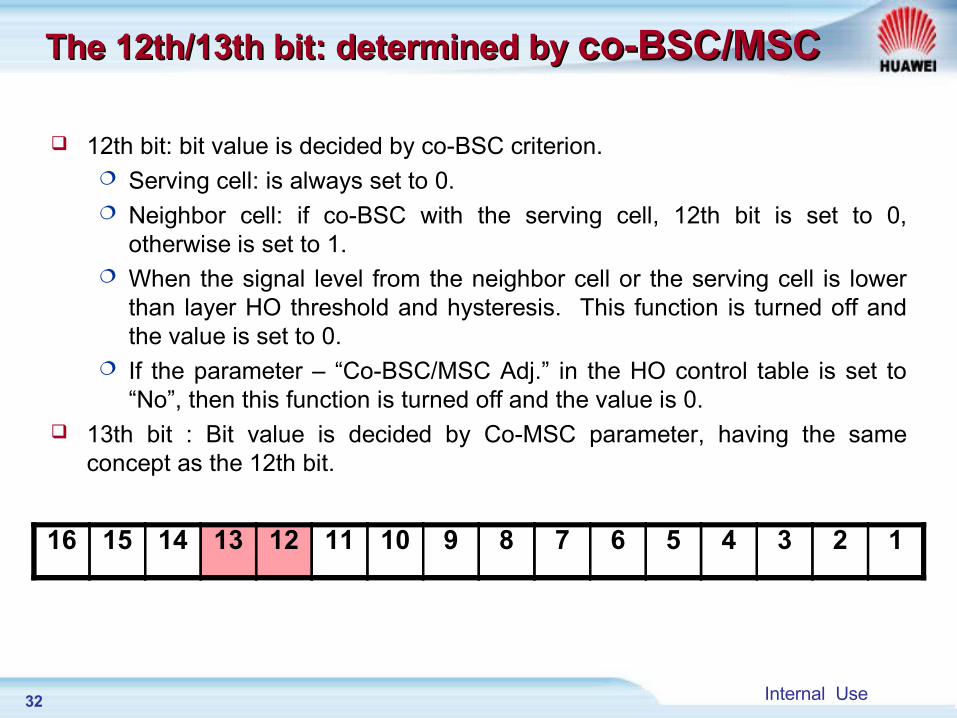
12th bit: bit value is decided by co-BSC criterion. Serving cell: is always set to 0. Neighbor cell: if co-BSC with the serving cell, 12th bit is set to 0,
otherwise is set to 1. When the signal level from the neighbor cell or the serving cell is lower
than layer HO threshold and hysteresis. This function is turned off and the value is set to 0.
If the parameter – “Co-BSC/MSC Adj.” in the HO control table is set to “No”, then this function is turned off and the value is 0.
13th bit : Bit value is decided by Co-MSC parameter, having the same concept as the 12th bit.
16 15 14 13 12 11 10 9 8 7 6 5 4 3 2 1
33 Internal Use
The 14th bit: determined by Layer HOThe 14th bit: determined by Layer HO
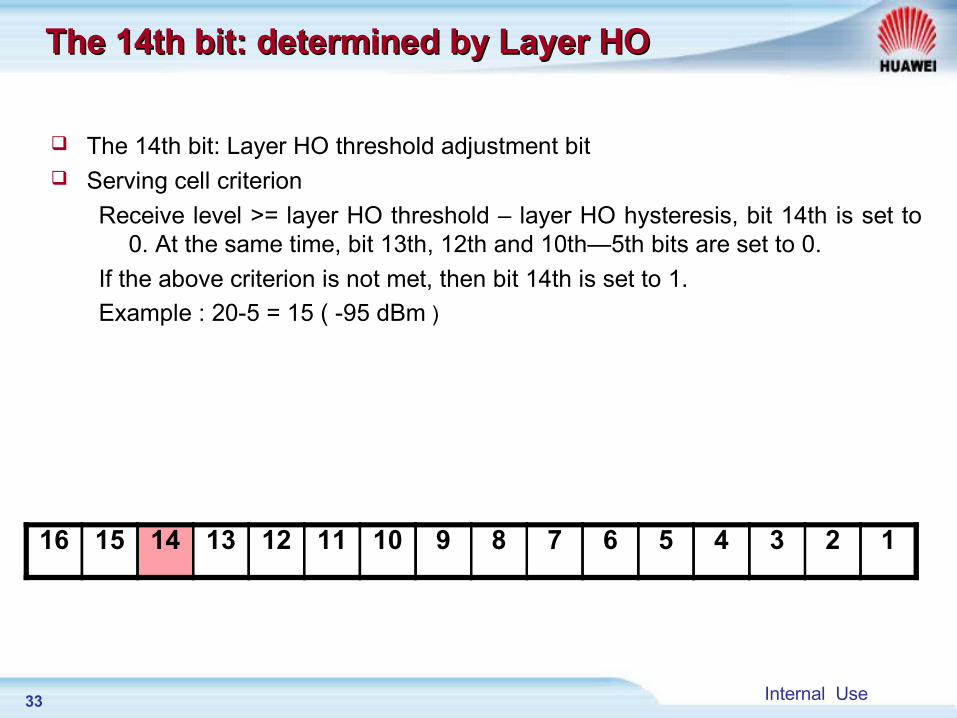
The 14th bit: Layer HO threshold adjustment bit Serving cell criterion
Receive level >= layer HO threshold – layer HO hysteresis, bit 14th is set to 0. At the same time, bit 13th, 12th and 10th—5th bits are set to 0.
If the above criterion is not met, then bit 14th is set to 1.
Example : 20-5 = 15 ( -95 dBm )
16 15 14 13 12 11 10 9 8 7 6 5 4 3 2 1
34 Internal Use
The 14th bit: determined by Layer HOThe 14th bit: determined by Layer HO
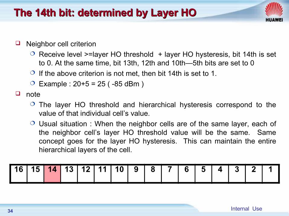
Neighbor cell criterion Receive level >=layer HO threshold + layer HO hysteresis, bit 14th is set
to 0. At the same time, bit 13th, 12th and 10th—5th bits are set to 0 If the above criterion is not met, then bit 14th is set to 1. Example : 20+5 = 25 ( -85 dBm )
note The layer HO threshold and hierarchical hysteresis correspond to the
value of that individual cell’s value. Usual situation : When the neighbor cells are of the same layer, each of
the neighbor cell’s layer HO threshold value will be the same. Same concept goes for the layer HO hysteresis. This can maintain the entire hierarchical layers of the cell.
16 15 14 13 12 11 10 9 8 7 6 5 4 3 2 1
35 Internal Use
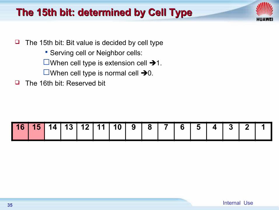
The 15th bit: determined by Cell TypeThe 15th bit: determined by Cell Type
The 15th bit: Bit value is decided by cell typeServing cell or Neighbor cells:When cell type is extension cell 1.When cell type is normal cell 0.
The 16th bit: Reserved bit
16 15 14 13 12 11 10 9 8 7 6 5 4 3 2 1
36 Internal Use
Chapter 2 Chapter 2 HO Algorithm processHO Algorithm process
Section 1 General HO process
Section 2 Measurement report preprocessing
Section 3 Penalty processing
Section 4 Basic ranking and Secondary ranking
Section 5 Condition of handover
37 Internal Use
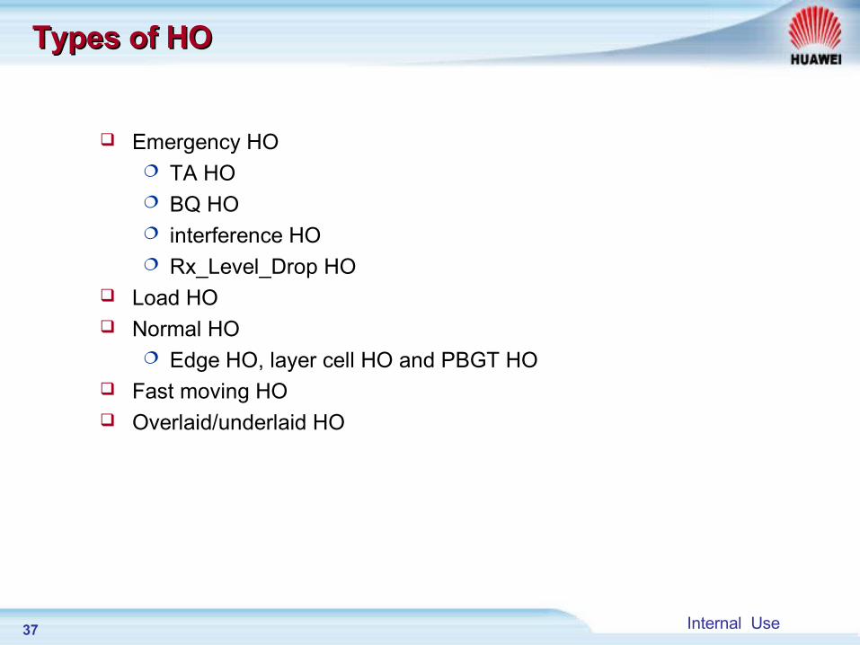
Types of HOTypes of HO
Emergency HO TA HO BQ HO interference HO Rx_Level_Drop HO
Load HO Normal HO
Edge HO, layer cell HO and PBGT HO Fast moving HO Overlaid/underlaid HO
38 Internal Use
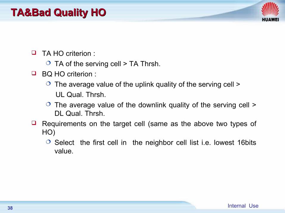
TA&Bad Quality HOTA&Bad Quality HO
TA HO criterion : TA of the serving cell > TA Thrsh.
BQ HO criterion : The average value of the uplink quality of the serving cell >
UL Qual. Thrsh. The average value of the downlink quality of the serving cell >
DL Qual. Thrsh. Requirements on the target cell (same as the above two types of
HO) Select the first cell in the neighbor cell list i.e. lowest 16bits
value.
39 Internal Use
Rx_Level_Drop HORx_Level_Drop HO
Rx_Level_Drop HO Due to downlink signal level drop Triggered upon detecting rapid level drop during MS busy
mode. Requirements for the target cell:
The target cell is the first cell in the neighbor cell list.
40 Internal Use
Interference HOInterference HO
Interference HO (DL&UL) : When the receiving level > receiving threshold level. But
Receiving quality < threshold of quality interference. Requirements for the target cell:
The target cell is in the cell list.
41 Internal Use
Cell Load HOCell Load HO
Cell Load HO Criterions : System load of BSC < Permissible load of HO threshold Load of serving cell > Load HO threshold
Requirements for the target cell Load of target cell < Load HO threshold
BTS
BSC
42 Internal Use
Edge HOEdge HO
Edge HO Criterion: In N seconds, when there are P seconds that neighbor cell’s
DL or MS’s UL signal level is lower than the Edge HO threshold. Then the criterion is met and Edge HO occurs. This method utilizes the P/N rule.
Requirements for the target cell: The target cell should be ranked in front of the serving cell.
43 Internal Use
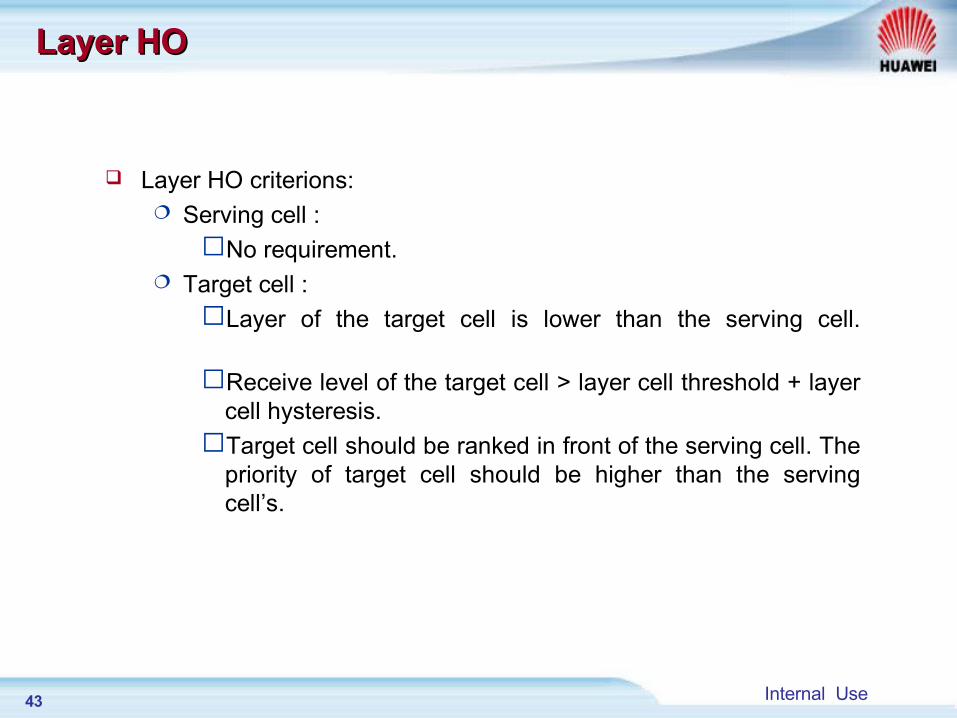
Layer HOLayer HO
Layer HO criterions: Serving cell : No requirement.
Target cell : Layer of the target cell is lower than the serving cell.
Receive level of the target cell > layer cell threshold + layer cell hysteresis.Target cell should be ranked in front of the serving cell. The
priority of target cell should be higher than the serving cell’s.
44 Internal Use
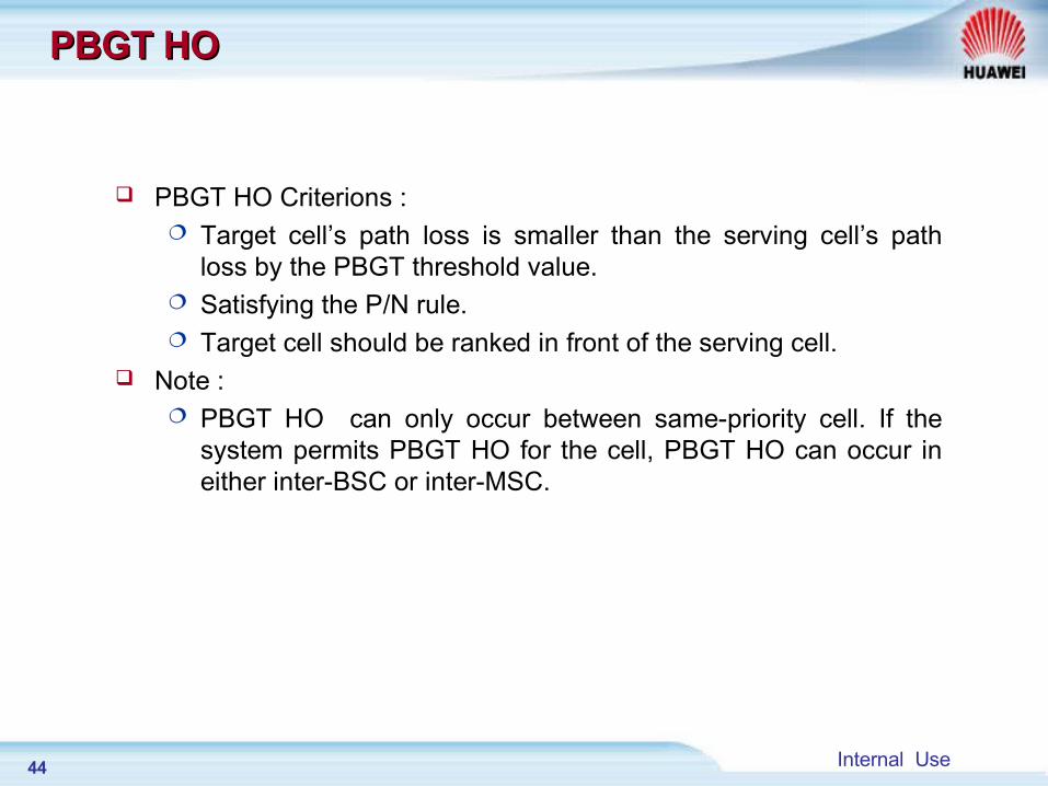
PBGT HOPBGT HO
PBGT HO Criterions : Target cell’s path loss is smaller than the serving cell’s path
loss by the PBGT threshold value. Satisfying the P/N rule. Target cell should be ranked in front of the serving cell.
Note : PBGT HO can only occur between same-priority cell. If the
system permits PBGT HO for the cell, PBGT HO can occur in either inter-BSC or inter-MSC.
45 Internal Use
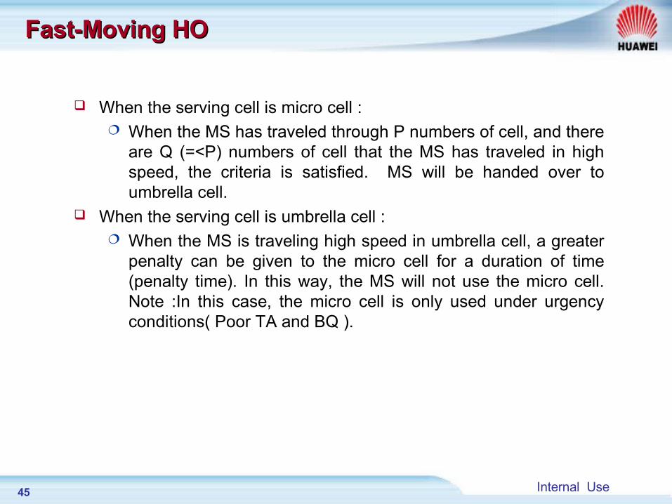
Fast-Moving HOFast-Moving HO
When the serving cell is micro cell : When the MS has traveled through P numbers of cell, and there
are Q (=<P) numbers of cell that the MS has traveled in high speed, the criteria is satisfied. MS will be handed over to umbrella cell.
When the serving cell is umbrella cell : When the MS is traveling high speed in umbrella cell, a greater
penalty can be given to the micro cell for a duration of time (penalty time). In this way, the MS will not use the micro cell. Note :In this case, the micro cell is only used under urgency conditions( Poor TA and BQ ).
46 Internal Use
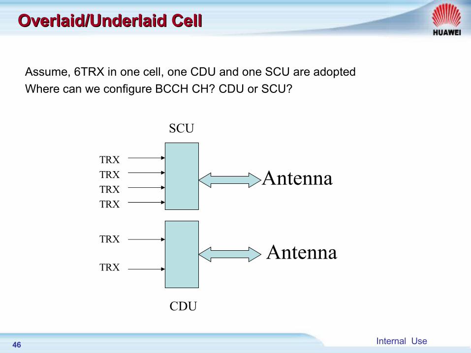
Overlaid/Underlaid CellOverlaid/Underlaid Cell
Assume, 6TRX in one cell, one CDU and one SCU are adopted
Where can we configure BCCH CH? CDU or SCU?
SCU
CDU
Antenna
Antenna
TRX
TRX
TRX
TRX
TRX
TRX
47 Internal Use
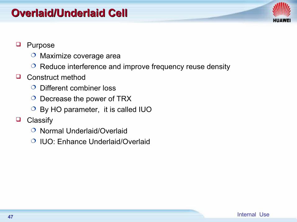
Overlaid/Underlaid CellOverlaid/Underlaid Cell
Purpose Maximize coverage area Reduce interference and improve frequency reuse density
Construct method Different combiner loss Decrease the power of TRX By HO parameter, it is called IUO
Classify Normal Underlaid/Overlaid IUO: Enhance Underlaid/Overlaid
48 Internal Use
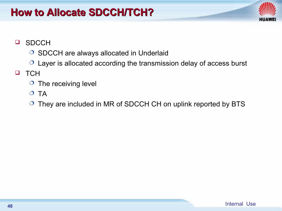
How to Allocate SDCCH/TCH?How to Allocate SDCCH/TCH?
SDCCH SDCCH are always allocated in Underlaid Layer is allocated according the transmission delay of access burst
TCH The receiving level TA They are included in MR of SDCCH CH on uplink reported by BTS
49 Internal Use
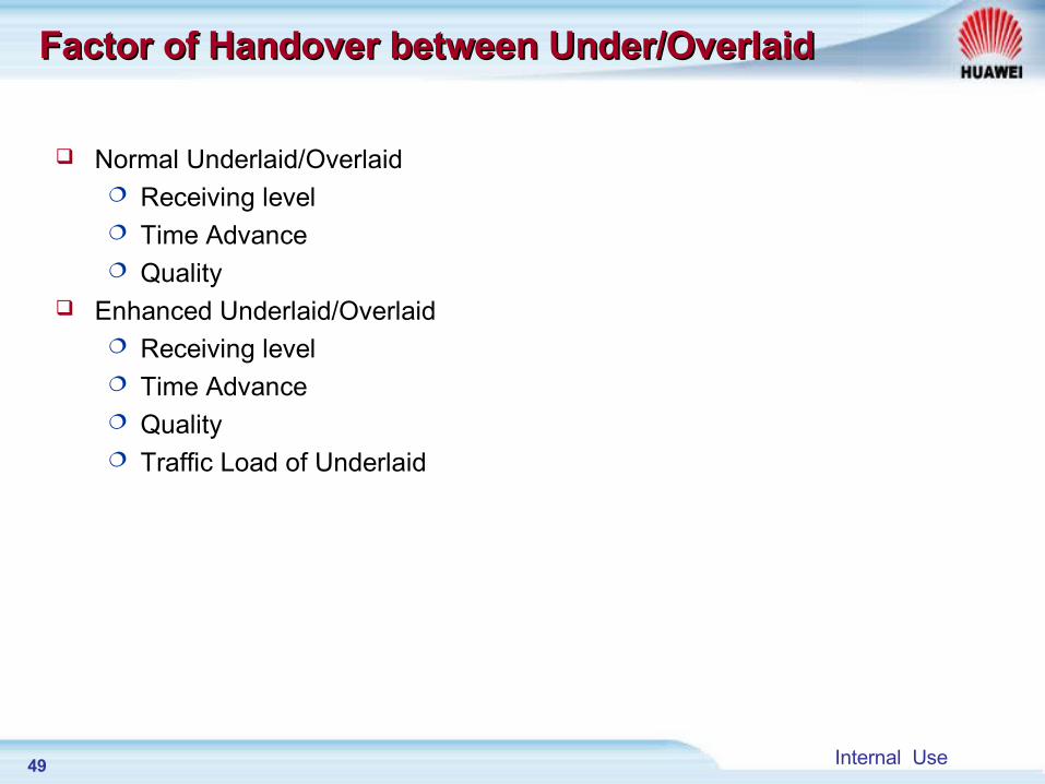
Factor of Handover between Under/OverlaidFactor of Handover between Under/Overlaid
Normal Underlaid/Overlaid Receiving level Time Advance Quality
Enhanced Underlaid/Overlaid Receiving level Time Advance Quality Traffic Load of Underlaid
50 Internal Use
underlaid
overlaid
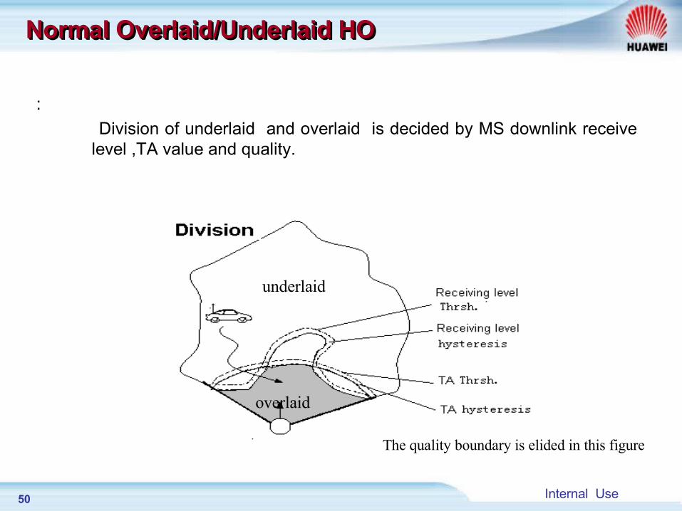
:
Division of underlaid and overlaid is decided by MS downlink receive level ,TA value and quality.
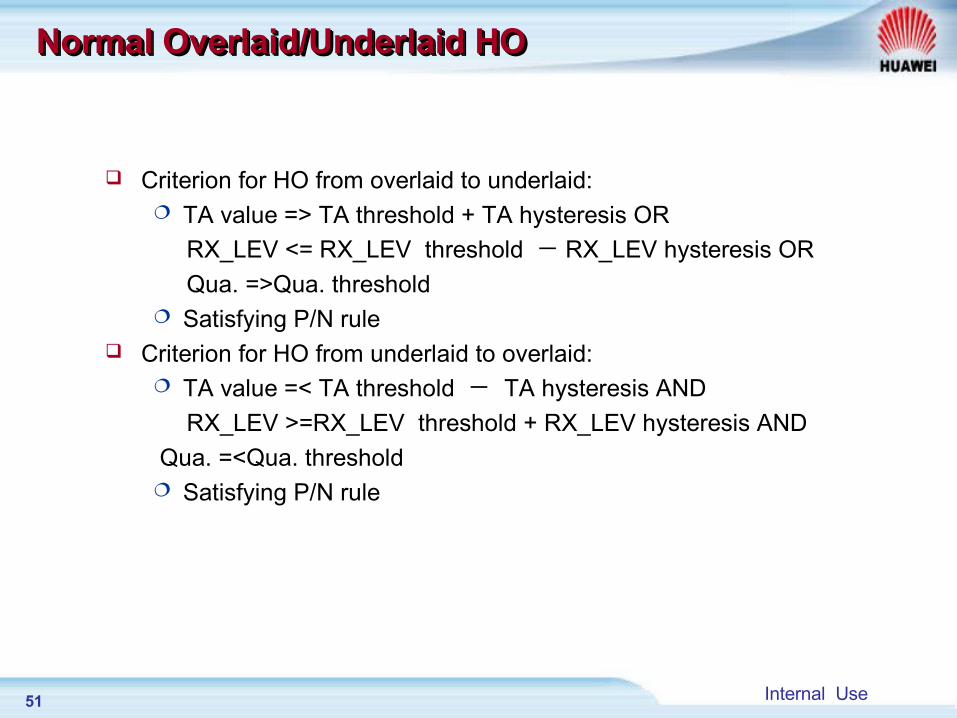
Normal Overlaid/Underlaid HONormal Overlaid/Underlaid HONormal Overlaid/Underlaid HONormal Overlaid/Underlaid HO
The quality boundary is elided in this figure
51 Internal Use
Criterion for HO from overlaid to underlaid: TA value => TA threshold + TA hysteresis OR
RX_LEV <= RX_LEV threshold - RX_LEV hysteresis OR
Qua. =>Qua. threshold Satisfying P/N rule
Criterion for HO from underlaid to overlaid: TA value =< TA threshold - TA hysteresis AND
RX_LEV >=RX_LEV threshold + RX_LEV hysteresis AND
Qua. =<Qua. threshold Satisfying P/N rule
Normal Overlaid/Underlaid HONormal Overlaid/Underlaid HONormal Overlaid/Underlaid HONormal Overlaid/Underlaid HO
52 Internal Use
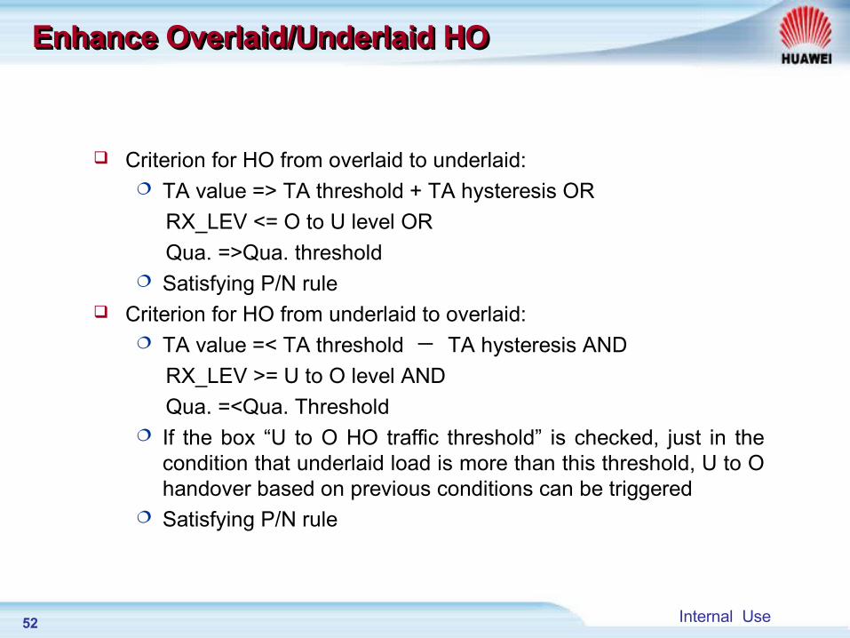
Criterion for HO from overlaid to underlaid: TA value => TA threshold + TA hysteresis OR
RX_LEV <= O to U level OR
Qua. =>Qua. threshold Satisfying P/N rule
Criterion for HO from underlaid to overlaid: TA value =< TA threshold - TA hysteresis AND
RX_LEV >= U to O level AND
Qua. =<Qua. Threshold If the box “U to O HO traffic threshold” is checked, just in the
condition that underlaid load is more than this threshold, U to O handover based on previous conditions can be triggered
Satisfying P/N rule
Enhance Overlaid/Underlaid HOEnhance Overlaid/Underlaid HOEnhance Overlaid/Underlaid HOEnhance Overlaid/Underlaid HO
53 Internal Use
Chapter 1 Introduction of Handover
Chapter 2 HO Algorithm process
Chapter 3 Chapter 3 HO Data ConfigurationHO Data Configuration
Chapter 4 HO Signaling process
54 Internal Use
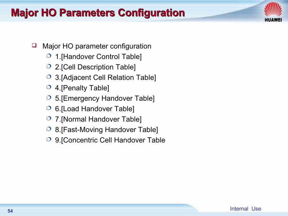
Major HO Parameters ConfigurationMajor HO Parameters Configuration
Major HO parameter configuration 1.[Handover Control Table] 2.[Cell Description Table] 3.[Adjacent Cell Relation Table] 4.[Penalty Table] 5.[Emergency Handover Table] 6.[Load Handover Table] 7.[Normal Handover Table] 8.[Fast-Moving Handover Table] 9.[Concentric Cell Handover Table
55 Internal Use
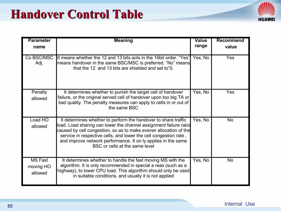
Parametername
Meaning Value range
Recommend value
Co BSC/MSCAdj.
It means whether the 12 and 13 bits acts in the 16bit order. “Yes” means handover in the same BSC/MSC is preferred. “No” means
that the 12 and 13 bits are shielded and set to”0.
Yes, No Yes
Penaltyallowed
It determines whether to punish the target cell of handover failure, or the original served cell of handover upon too big TA or bad quality. The penalty measures can apply to cells in or out of
the same BSC
Yes, No Yes
Load HOallowed
It determines whether to perform the handover to share traffic load. Load sharing can lower the channel assignment failure ratio caused by cell congestion, so as to make evener allocation of the
service in respective cells, and lower the cell congestion rate , and improve network performance. It on ly applies in the same
BSC or cells at the same level
Yes, No No
MS Fastmoving HO
allowed
It determines whether to handle the fast moving MS with the algorithm. It is only recommended in special a reas (such as a
highway), to lower CPU load. This algorithm should only be used in suitable conditions, and usually it is not applied
Yes, No No
Handover Control TableHandover Control Table
56 Internal Use
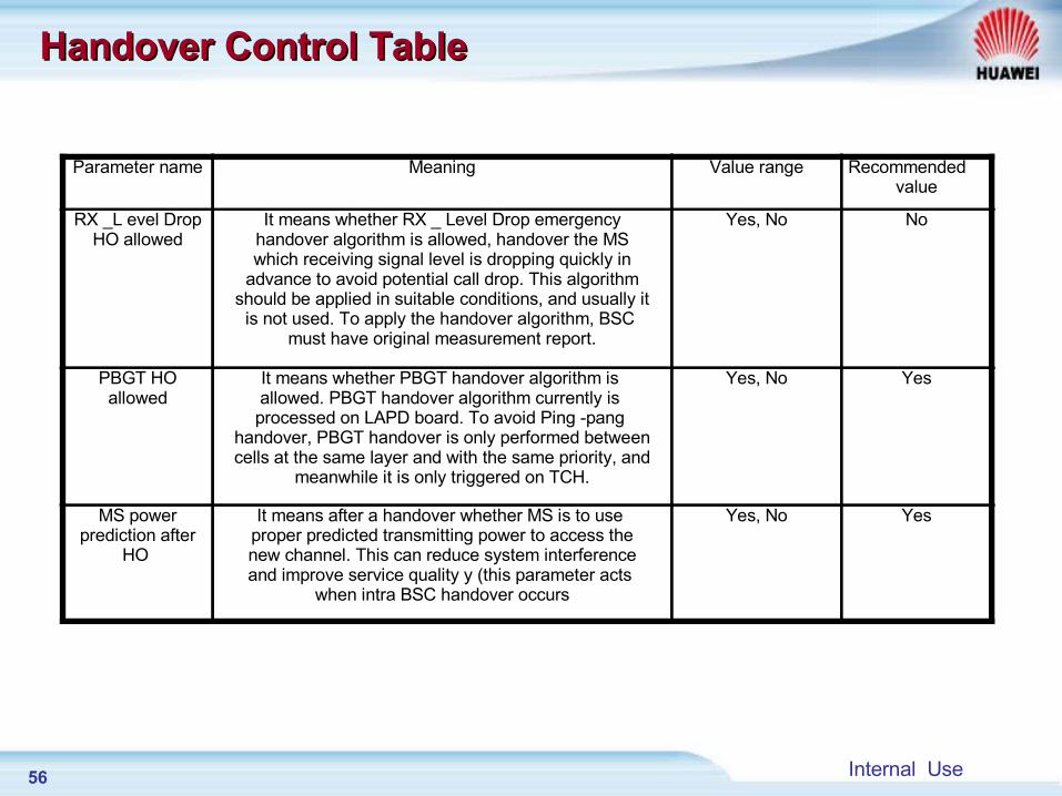
Parameter name Meaning Value range Recommended value
RX _L evel DropHO allowed
It means whether RX _ Level Drop emergencyhandover algorithm is allowed, handover the MSwhich receiving signal level is dropping quickly in
advance to avoid potential call drop. This algorithmshould be applied in suitable conditions, and usually it
is not used. To apply the handover algorithm, BSC must have original measurement report.
Yes, No No
PBGT HOallowed
It means whether PBGT handover algorithm is allowed. PBGT handover algorithm currently is processed on LAPD board. To avoid Ping -pang
handover, PBGT handover is only performed betweencells at the same layer and with the same priority, and
meanwhile it is only triggered on TCH.
Yes, No Yes
MS powerprediction after
HO
It means after a handover whether MS is to use proper predicted transmitting power to access thenew channel. This can reduce system interferenceand improve service quality y (this parameter acts
when intra BSC handover occurs
Yes, No Yes
Handover Control TableHandover Control Table
57 Internal Use
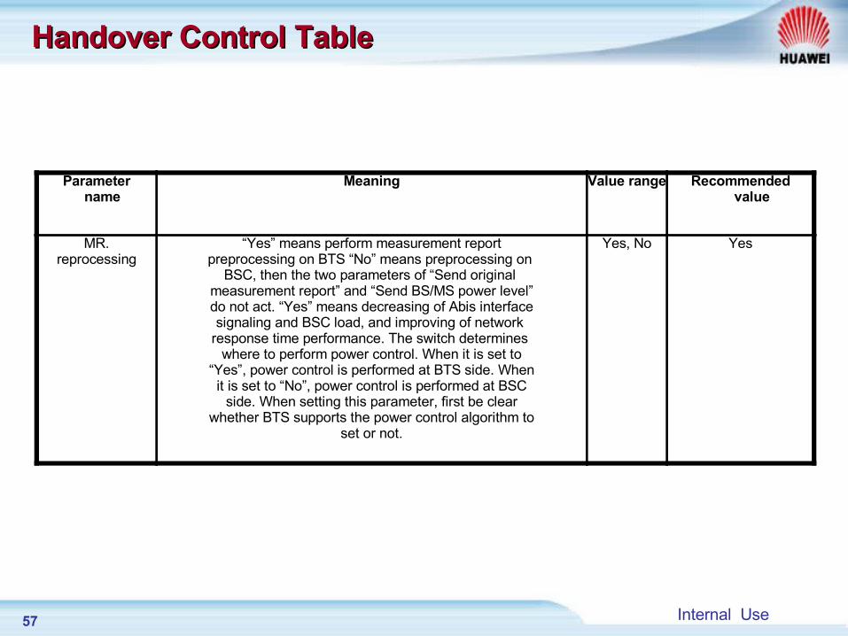
Parameter name
Meaning Value range Recommended value
MR.reprocessing
“Yes” means perform measurement reportpreprocessing on BTS “No” means preprocessing on
BSC, then the two parameters of “Send original measurement report” and “Send BS/MS power level”do not act. “Yes” means decreasing of Abis interfacesignaling and BSC load, and improving of network
response time performance. The switch determines where to perform power control. When it is set to
“Yes”, power control is performed at BTS side. Whenit is set to “No”, power control is performed at BSC
side. When setting this parameter, first be clearwhether BTS supports the power control algorithm to
set or not.
Yes, No Yes
Handover Control TableHandover Control Table
58 Internal Use
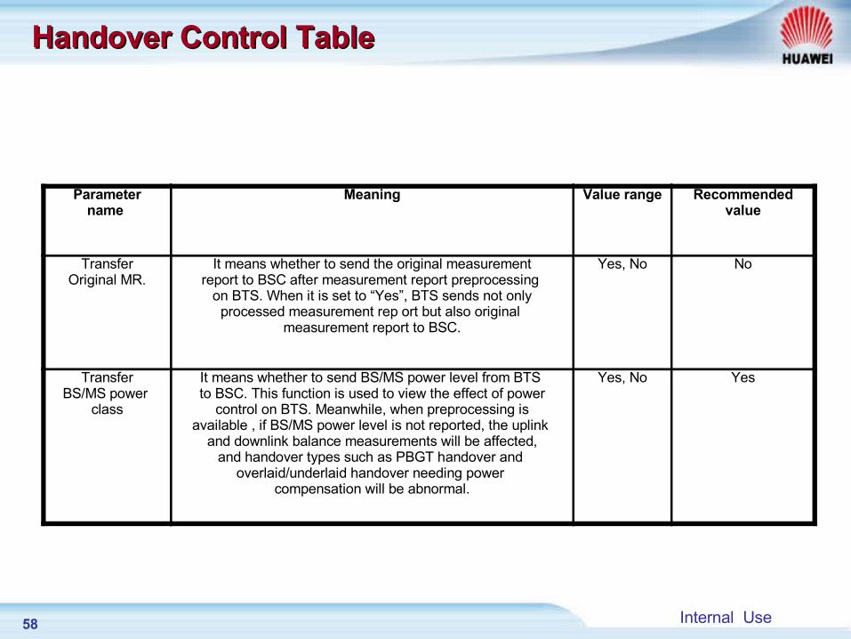
Parametername
Meaning Value range Recommendedvalue
TransferOriginal MR.
It means whether to send the original measurementreport to BSC after measurement report preprocessing
on BTS. When it is set to “Yes”, BTS sends not onlyprocessed measurement rep ort but also original
measurement report to BSC.
Yes, No No
TransferBS/MS power
class
It means whether to send BS/MS power level from BTS to BSC. This function is used to view the effect of power
control on BTS. Meanwhile, when preprocessing isavailable , if BS/MS power level is not reported, the uplink
and downlink balance measurements will be affected,and handover types such as PBGT handover and
overlaid/underlaid handover needing power compensation will be abnormal.
Yes, No Yes
Handover Control TableHandover Control Table
59 Internal Use
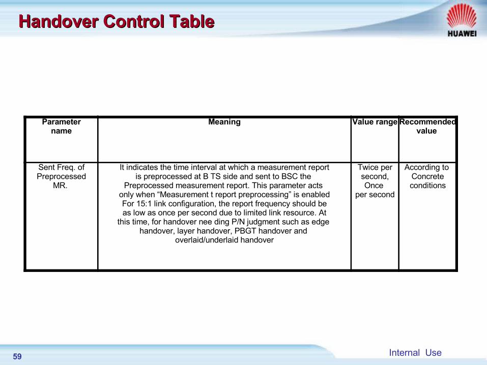
Parametername
Meaning Value range Recommendedvalue
Sent Freq. ofPreprocessed
MR.
It indicates the time interval at which a measurement reportis preprocessed at B TS side and sent to BSC the
Preprocessed measurement report. This parameter acts only when “Measurement t report preprocessing” is enabledFor 15:1 link configuration, the report frequency should beas low as once per second due to limited link resource. At
this time, for handover nee ding P/N judgment such as edge handover, layer handover, PBGT handover and
overlaid/underlaid handover
Twice persecond, Once
per second
According to Concreteconditions
Handover Control TableHandover Control Table
60 Internal Use
Parametername
Meaning Valuerange
Recommended value
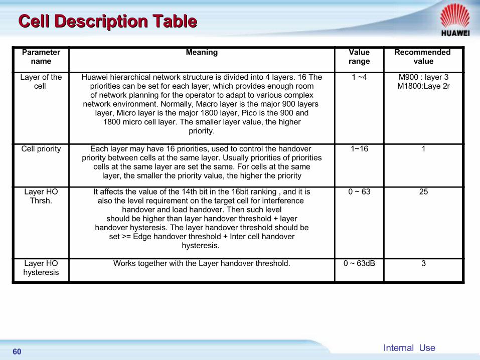
Layer of thecell
Huawei hierarchical network structure is divided into 4 layers. 16 Thepriorities can be set for each layer, which provides enough roomof network planning for the operator to adapt to various complex
network environment. Normally, Macro layer is the major 900 layers layer, Micro layer is the major 1800 layer, Pico is the 900 and
1800 micro cell layer. The smaller layer value, the higherpriority.
1 ~4 M900 : layer 3M1800:Laye 2r
Cell priority Each layer may have 16 priorities, used to control the handover priority between cells at the same layer. Usually priorities of priorities
cells at the same layer are set the same. For cells at the samelayer, the smaller the priority value, the higher the priority
1~16 1
Layer HOThrsh.
It affects the value of the 14th bit in the 16bit ranking , and it isalso the level requirement on the target cell for interference
handover and load handover. Then such level should be higher than layer handover threshold + layer
handover hysteresis. The layer handover threshold should beset >= Edge handover threshold + Inter cell handover
hysteresis.
0 ~ 63 25
Layer HOhysteresis
Works together with the Layer handover threshold. 0 ~ 63dB 3
Cell Description TableCell Description Table
61 Internal Use
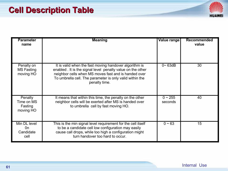
Parametername
Meaning Value range Recommendedvalue
Penalty onMS Fastingmoving HO
It is valid when the fast moving handover algorithm isenabled . It is the signal level penalty value on the otherneighbor cells when MS moves fast and is handed overTo umbrella cell. The parameter is only valid within the
penalty time.
0~ 63dB 30
PenaltyTime on MS
Fastingmoving HO
It means that within this time, the penalty on the otherneighbor cells will be exerted after MS is handed over
to umbrella cell by fast moving HO.
0 ~ 255seconds
40
Min DL level 0n
Candidatecell
This is the min signal level requirement for the cell itself to be a candidate cell low configuration may easily
cause call drops, while too high a configuration mightturn handover too hard to occur.
0 ~ 63 15
Cell Description TableCell Description Table
62 Internal Use
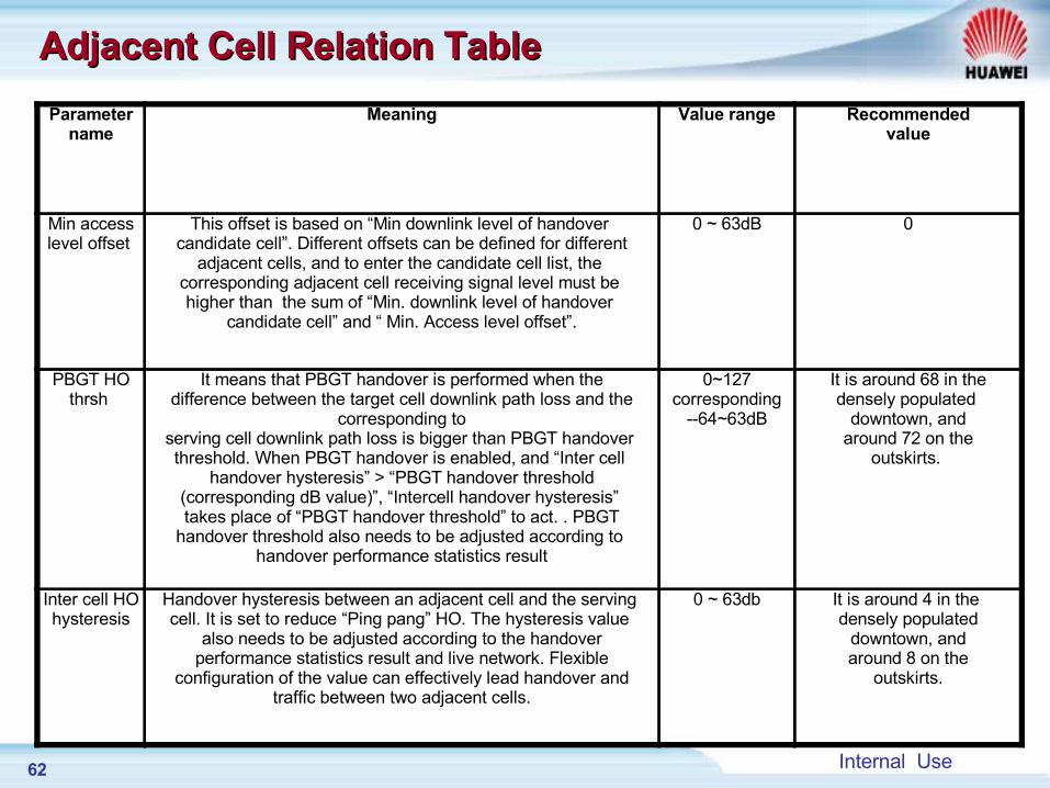
Parametername
Meaning Value range Recommendedvalue
Min accesslevel offset
This offset is based on “Min downlink level of handover candidate cell”. Different offsets can be defined for different
adjacent cells, and to enter the candidate cell list, the corresponding adjacent cell receiving signal level must be higher than the sum of “Min. downlink level of handover
candidate cell” and “ Min. Access level offset”.
0 ~ 63dB 0
PBGT HOthrsh
It means that PBGT handover is performed when thedifference between the target cell downlink path loss and the
corresponding toserving cell downlink path loss is bigger than PBGT handover threshold. When PBGT handover is enabled, and “Inter cell
handover hysteresis” > “PBGT handover threshold(corresponding dB value)”, “Intercell handover hysteresis” takes place of “PBGT handover threshold” to act. . PBGT
handover threshold also needs to be adjusted according to handover performance statistics result
0~127 corresponding
--64~63dB
It is around 68 in thedensely populated
downtown, andaround 72 on the
outskirts.
Inter cell HOhysteresis
Handover hysteresis between an adjacent cell and the serving cell. It is set to reduce “Ping pang” HO. The hysteresis value
also needs to be adjusted according to the handoverperformance statistics result and live network. Flexible
configuration of the value can effectively lead handover andtraffic between two adjacent cells.
0 ~ 63db It is around 4 in the densely populated
downtown, andaround 8 on the
outskirts.
Adjacent Cell Relation TableAdjacent Cell Relation Table
63 Internal Use
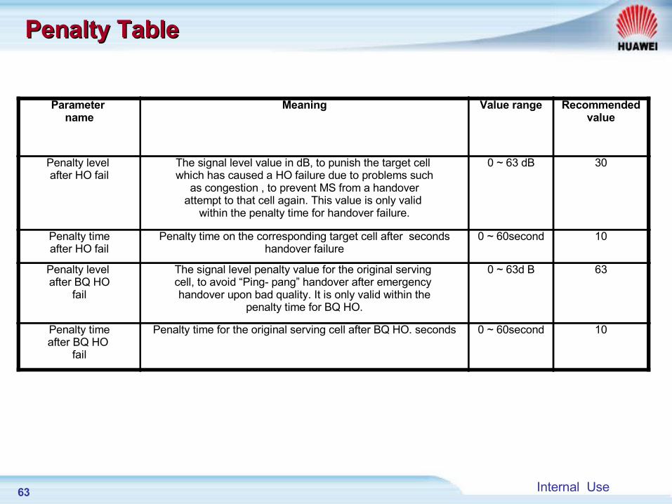
Parameter name
Meaning Value range Recommendedvalue
Penalty level after HO fail
The signal level value in dB, to punish the target cell which has caused a HO failure due to problems such
as congestion , to prevent MS from a handoverattempt to that cell again. This value is only valid
within the penalty time for handover failure.
0 ~ 63 dB 30
Penalty timeafter HO fail
Penalty time on the corresponding target cell after secondshandover failure
0 ~ 60second 10
Penalty level after BQ HO
fail
The signal level penalty value for the original serving cell, to avoid “Ping- pang” handover after emergency handover upon bad quality. It is only valid within the
penalty time for BQ HO.
0 ~ 63d B 63
Penalty timeafter BQ HO
fail
Penalty time for the original serving cell after BQ HO. seconds 0 ~ 60second 10
Penalty TablePenalty Table
64 Internal Use
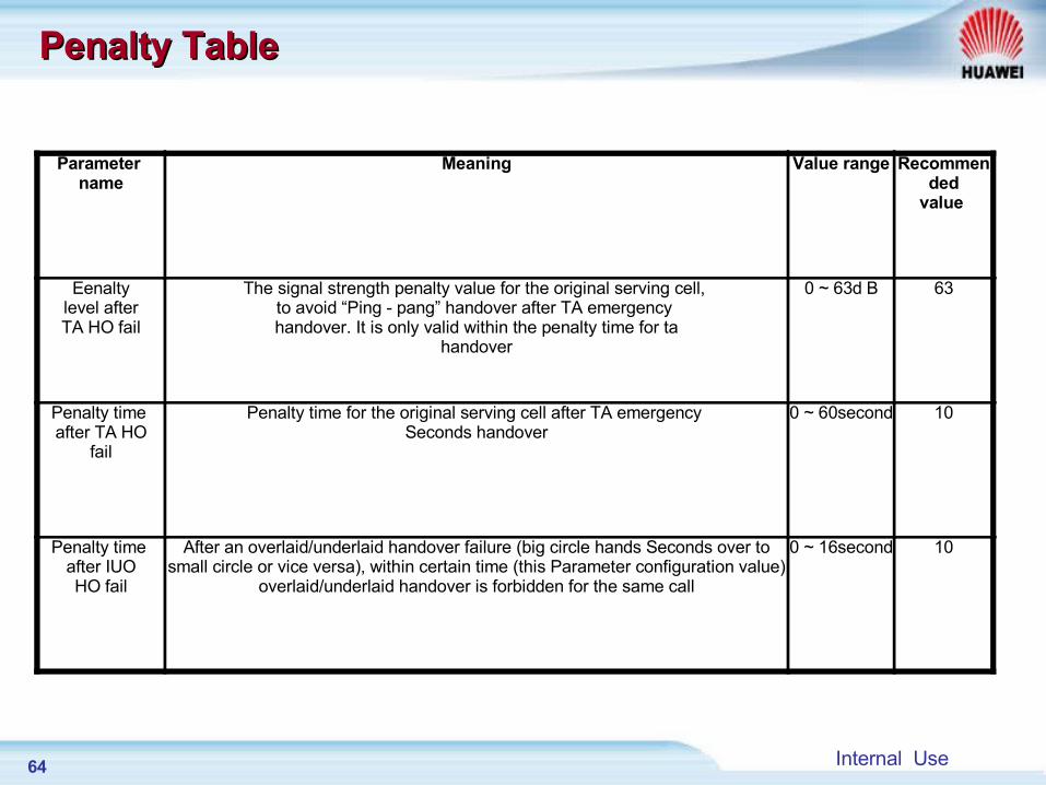
Parameter name
Meaning Value range Recommended
value
Eenaltylevel afterTA HO fail
The signal strength penalty value for the original serving cell, to avoid “Ping - pang” handover after TA emergency handover. It is only valid within the penalty time for ta
handover
0 ~ 63d B 63
Penalty time after TA HO
fail
Penalty time for the original serving cell after TA emergency Seconds handover
0 ~ 60second 10
Penalty time after IUOHO fail
After an overlaid/underlaid handover failure (big circle hands Seconds over to small circle or vice versa), within certain time (this Parameter configuration value)
overlaid/underlaid handover is forbidden for the same call
0 ~ 16second 10
Penalty TablePenalty Table
65 Internal Use
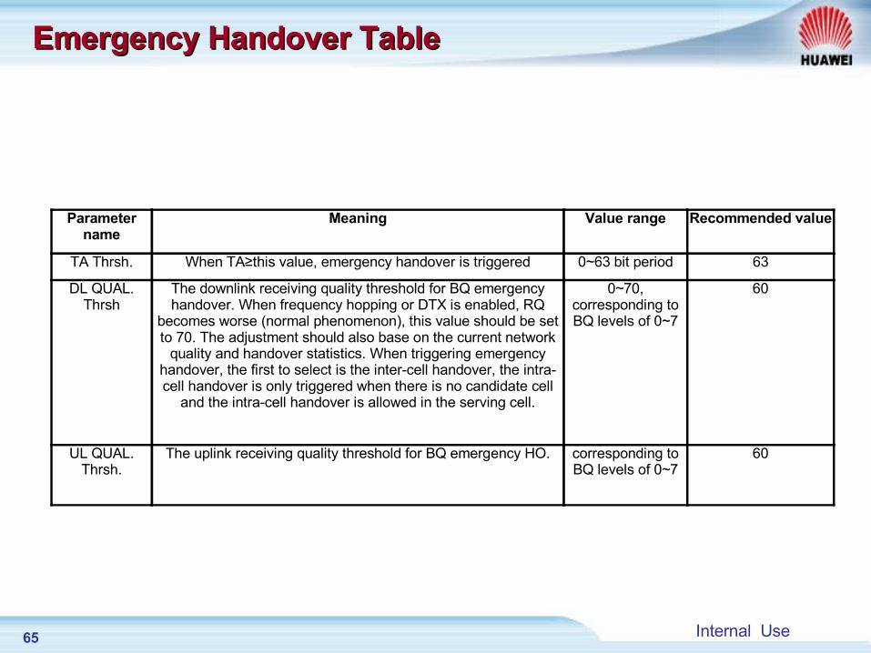
Emergency Handover Table Emergency Handover Table
Parameter name
Meaning Value range Recommended value
TA Thrsh. When TA≥this value, emergency handover is triggered 0~63 bit period 63
DL QUAL. Thrsh
The downlink receiving quality threshold for BQ emergency handover. When frequency hopping or DTX is enabled, RQ
becomes worse (normal phenomenon), this value should be set to 70. The adjustment should also base on the current network
quality and handover statistics. When triggering emergency handover, the first to select is the inter-cell handover, the intra-cell handover is only triggered when there is no candidate cell
and the intra-cell handover is allowed in the serving cell.
0~70, corresponding to BQ levels of 0~7
60
UL QUAL. Thrsh.
The uplink receiving quality threshold for BQ emergency HO. corresponding to BQ levels of 0~7
60
66 Internal Use
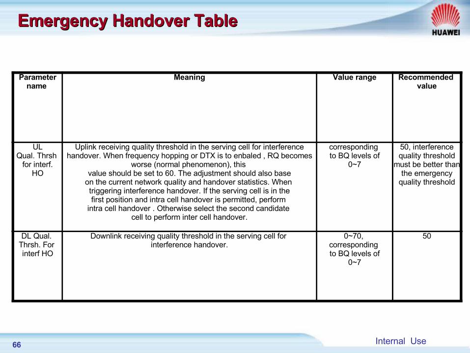
Parametername
Meaning Value range Recommended value
ULQual. Thrsh
for interf.HO
Uplink receiving quality threshold in the serving cell for interference handover. When frequency hopping or DTX is to enbaled , RQ becomes
worse (normal phenomenon), this value should be set to 60. The adjustment should also base
on the current network quality and handover statistics. When triggering interference handover. If the serving cell is in thefirst position and intra cell handover is permitted, perform
intra cell handover . Otherwise select the second candidate cell to perform inter cell handover.
corresponding to BQ levels of
0~7
50, interferencequality threshold
must be better than the emergency
quality threshold
DL Qual. Thrsh. For interf HO
Downlink receiving quality threshold in the serving cell for interference handover.
0~70, corresponding to BQ levels of
0~7
50
Emergency Handover TableEmergency Handover Table
67 Internal Use
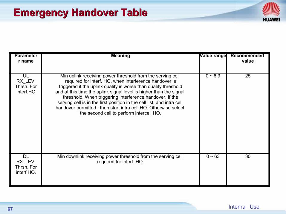
Parameterr name
Meaning Value range Recommended value
ULRX_LEV Thrsh. Forinterf.HO
Min uplink receiving power threshold from the serving cell required for interf. HO, when interference handover is
triggered if the uplink quality is worse than quality thresholdand at this time the uplink signal level is higher than the signal
threshold. When triggering interference handover, If theserving cell is in the first position in the cell list, and intra cell
handover permitted , then start intra cell HO. Otherwise select the second cell to perform intercell HO.
0 ~ 6 3 25
DLRX_LEV Thrsh. Forinterf HO.
Min downlink receiving power threshold from the serving cell required for interf. HO.
0 ~ 63 30
Emergency Handover TableEmergency Handover Table
68 Internal Use
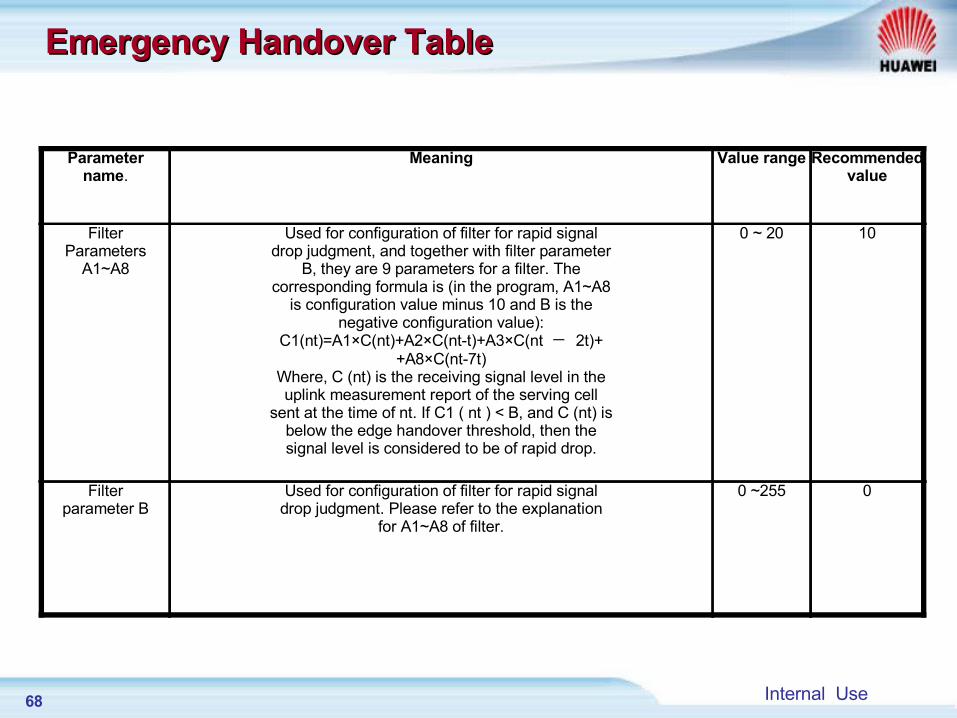
Parametername.
Meaning Value range Recommendedvalue
FilterParameters
A1~A8
Used for configuration of filter for rapid signaldrop judgment, and together with filter parameter
B, they are 9 parameters for a filter. Thecorresponding formula is (in the program, A1~A8
is configuration value minus 10 and B is thenegative configuration value):
C1(nt)=A1×C(nt)+A2×C(nt-t)+A3×C(nt - 2t)++A8×C(nt-7t)
Where, C (nt) is the receiving signal level in theuplink measurement report of the serving cell
sent at the time of nt. If C1 ( nt ) < B, and C (nt) isbelow the edge handover threshold, then thesignal level is considered to be of rapid drop.
0 ~ 20 10
Filterparameter B
Used for configuration of filter for rapid signaldrop judgment. Please refer to the explanation
for A1~A8 of filter.
0 ~255 0
Emergency Handover TableEmergency Handover Table
69 Internal Use
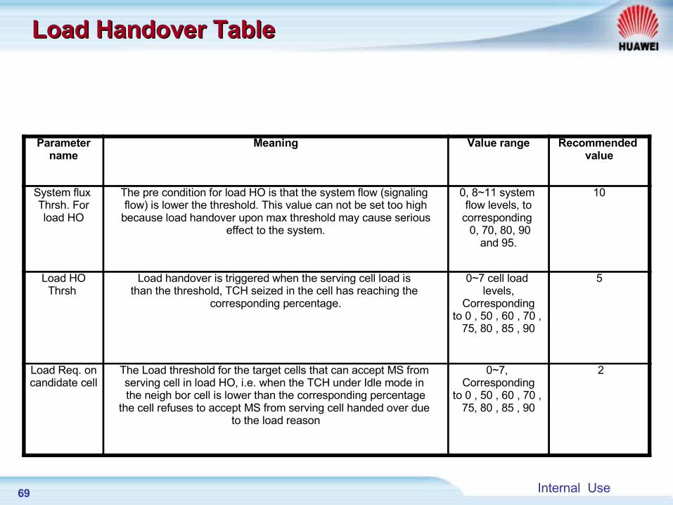
Parametername
Meaning Value range Recommended value
System flux Thrsh. Forload HO
The pre condition for load HO is that the system flow (signaling flow) is lower the threshold. This value can not be set too high
because load handover upon max threshold may cause seriouseffect to the system.
0, 8~11 system flow levels, to
corresponding 0, 70, 80, 90
and 95.
10
Load HOThrsh
Load handover is triggered when the serving cell load is than the threshold, TCH seized in the cell has reaching the
corresponding percentage.
0~7 cell load levels,
Correspondingto 0 , 50 , 60 , 70 ,
75, 80 , 85 , 90
5
Load Req. oncandidate cell
The Load threshold for the target cells that can accept MS from serving cell in load HO, i.e. when the TCH under Idle mode in the neigh bor cell is lower than the corresponding percentage
the cell refuses to accept MS from serving cell handed over due to the load reason
0~7, Corresponding
to 0 , 50 , 60 , 70 , 75, 80 , 85 , 90
2
Load Handover TableLoad Handover Table
70 Internal Use
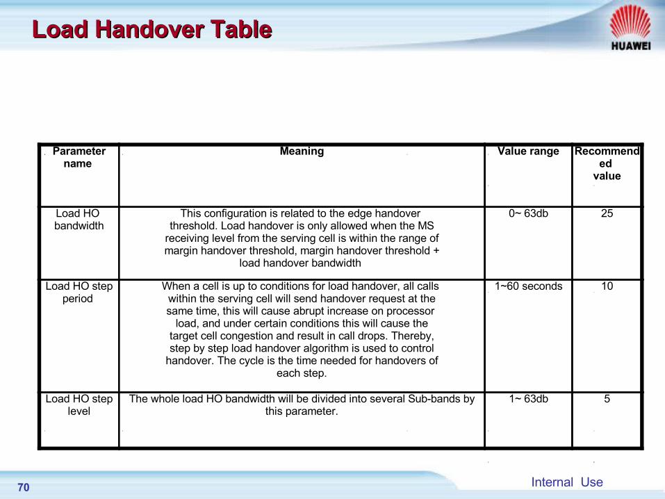
Load Handover TableLoad Handover Table
Parametername
Meaning Value range Recommended
value
Load HO bandwidth
This configuration is related to the edge handover threshold. Load handover is only allowed when the MS
receiving level from the serving cell is within the range ofmargin handover threshold, margin handover threshold +
load handover bandwidth
0~ 63db 25
Load HO stepperiod
When a cell is up to conditions for load handover, all calls within the serving cell will send handover request at thesame time, this will cause abrupt increase on processor
load, and under certain conditions this will cause thetarget cell congestion and result in call drops. Thereby,step by step load handover algorithm is used to control
handover. The cycle is the time needed for handovers ofeach step.
1~60 seconds 10
Load HO steplevel
The whole load HO bandwidth will be divided into several Sub-bands by this parameter.
1~ 63db 5
71 Internal Use
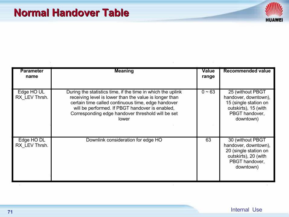
Normal Handover TableNormal Handover Table
Parametername
Meaning Value range
Recommended value
Edge HO UL RX_LEV Thrsh.
During the statistics time, if the time in which the uplinkreceiving level is lower than the value is longer thancertain time called continuous time, edge handover
will be performed. If PBGT handover is enabled,Corresponding edge handover threshold will be set
lower
0 ~ 63 25 (without PBGThandover, downtown),15 (single station onoutskirts), 15 (withPBGT handover,
downtown)
Edge HO DLRX_LEV Thrsh.
Downlink consideration for edge HO 63 30 (without PBGThandover, downtown),20 (single station onoutskirts), 20 (withPBGT handover,
downtown)
72 Internal Use
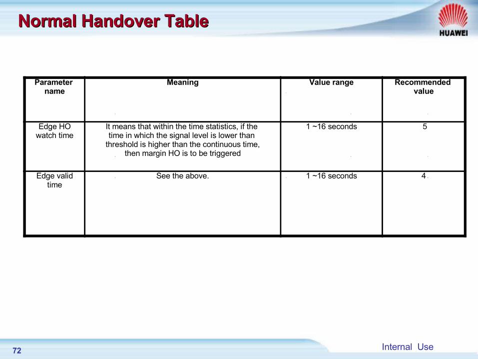
Normal Handover Table Normal Handover Table
Parameter name
Meaning Value range Recommended value
Edge HOwatch time
It means that within the time statistics, if the time in which the signal level is lower than
threshold is higher than the continuous time,then margin HO is to be triggered
1 ~16 seconds 5
Edge validtime
See the above. 1 ~16 seconds 4
73 Internal Use
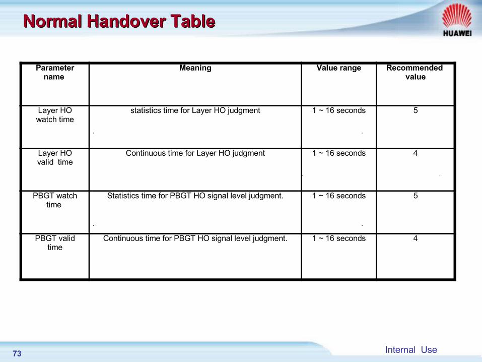
Normal Handover TableNormal Handover Table
Parametername
Meaning Value range Recommended value
Layer HOwatch time
statistics time for Layer HO judgment 1 ~ 16 seconds 5
Layer HOvalid time
Continuous time for Layer HO judgment 1 ~ 16 seconds 4
PBGT watchtime
Statistics time for PBGT HO signal level judgment. 1 ~ 16 seconds 5
PBGT validtime
Continuous time for PBGT HO signal level judgment. 1 ~ 16 seconds 4
74 Internal Use
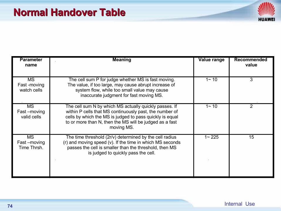
Normal Handover TableNormal Handover Table
Parametername
Meaning Value range Recommended value
MSFast -movingwatch cells
The cell sum P for judge whether MS is fast moving.The value, if too large, may cause abrupt increase of
system flow, while too small value may causeinaccurate judgment for fast moving MS.
1~ 10 3
MS Fast –moving
valid cells
The cell sum N by which MS actually quickly passes. If within P cells that MS continuously past, the number ofcells by which the MS is judged to pass quickly is equalto or more than N, then the MS will be judged as a fast
moving MS.
1~ 10 2
MS Fast –movingTime Thrsh.
The time threshold (2r/v) determined by the cell radius (r) and moving speed (v). If the time in which MS seconds
passes the cell is smaller than the threshold, then MSis judged to quickly pass the cell.
1~ 225 15
75 Internal Use
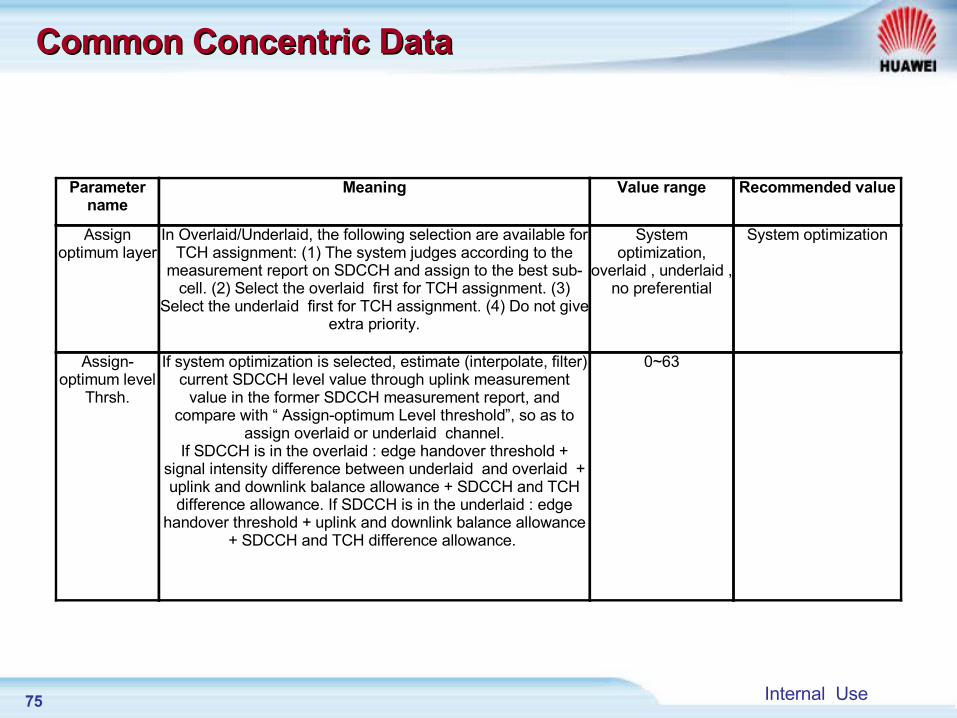
Common Concentric Data Common Concentric Data
Parameter name
Meaning Value range Recommended value
Assign optimum layer
In Overlaid/Underlaid, the following selection are available for TCH assignment: (1) The system judges according to the
measurement report on SDCCH and assign to the best sub-cell. (2) Select the overlaid first for TCH assignment. (3)
Select the underlaid first for TCH assignment. (4) Do not give extra priority.
System optimization,
overlaid , underlaid , no preferential
System optimization
Assign-optimum level
Thrsh.
If system optimization is selected, estimate (interpolate, filter) current SDCCH level value through uplink measurement
value in the former SDCCH measurement report, and compare with “ Assign-optimum Level threshold”, so as to
assign overlaid or underlaid channel.If SDCCH is in the overlaid : edge handover threshold +
signal intensity difference between underlaid and overlaid + uplink and downlink balance allowance + SDCCH and TCH difference allowance. If SDCCH is in the underlaid : edge
handover threshold + uplink and downlink balance allowance + SDCCH and TCH difference allowance.
0~63
76 Internal Use
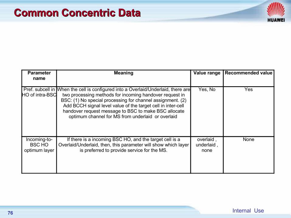
Common Concentric DataCommon Concentric Data
Parametername
Meaning Value range Recommended value
Pref. subcell in HO of intra-BSC
When the cell is configured into a Overlaid/Underlaid, there are two processing methods for incoming handover request in
BSC: (1) No special processing for channel assignment. (2) Add BCCH signal level value of the target cell in inter-cell handover request message to BSC to make BSC allocate
optimum channel for MS from underlaid or overlaid
Yes, No Yes
Incoming-to-BSC HO
optimum layer
If there is a incoming BSC HO, and the target cell is a Overlaid/Underlaid, then, this parameter will show which layer
is preferred to provide service for the MS.
overlaid , underlaid ,
none
None
77 Internal Use
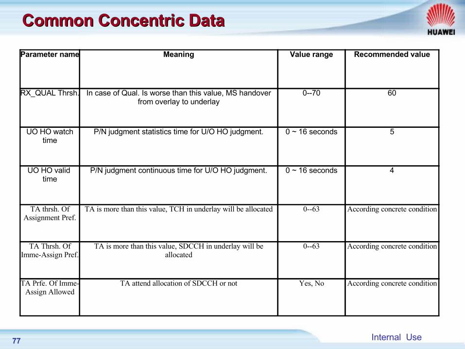
Common Concentric DataCommon Concentric Data
Parameter name Meaning Value range Recommended value
RX_QUAL Thrsh. In case of Qual. Is worse than this value, MS handover from overlay to underlay
0--70 60
UO HO watch time
P/N judgment statistics time for U/O HO judgment. 0 ~ 16 seconds 5
UO HO valid time
P/N judgment continuous time for U/O HO judgment. 0 ~ 16 seconds 4
TA thrsh. Of Assignment Pref.
TA is more than this value, TCH in underlay will be allocated 0--63 According concrete condition
TA Thrsh. Of Imme-Assign Pref.
TA is more than this value, SDCCH in underlay will be allocated
0--63 According concrete condition
TA Prfe. Of Imme-Assign Allowed
TA attend allocation of SDCCH or not Yes, No According concrete condition
78 Internal Use
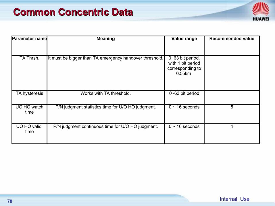
Common Concentric DataCommon Concentric Data
Parameter name Meaning Value range Recommended value
TA Thrsh. It must be bigger than TA emergency handover threshold. 0~63 bit period, with 1 bit period corresponding to
0.55km
TA hysteresis Works with TA threshold. 0~63 bit period
UO HO watch time
P/N judgment statistics time for U/O HO judgment. 0 ~ 16 seconds 5
UO HO valid time
P/N judgment continuous time for U/O HO judgment. 0 ~ 16 seconds 4
79 Internal Use
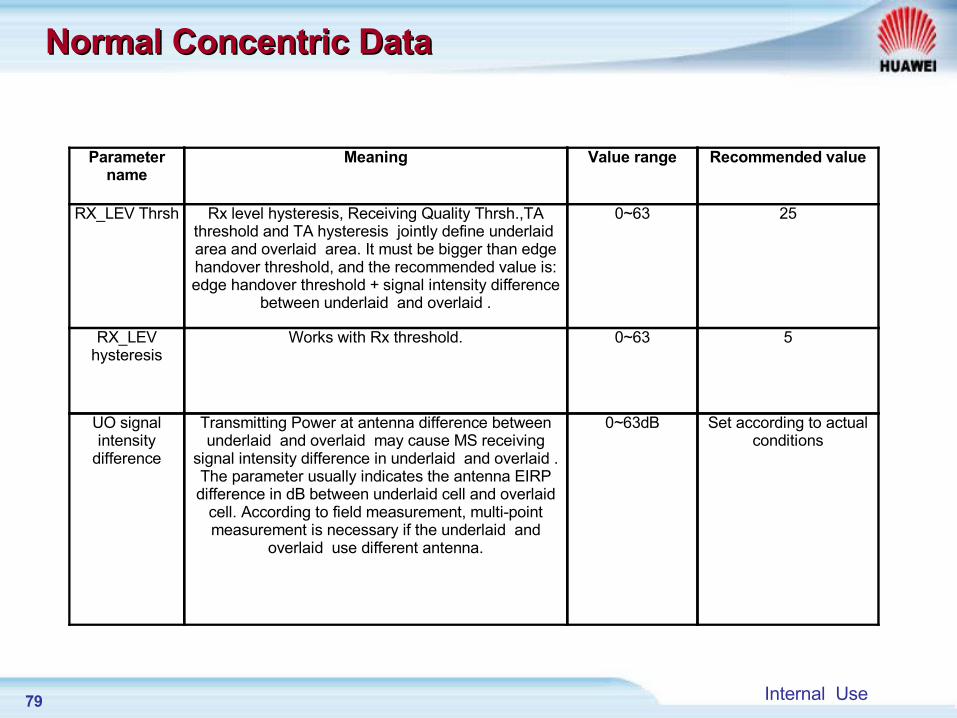
Normal Concentric DataNormal Concentric Data
Parameter name
Meaning Value range Recommended value
RX_LEV Thrsh Rx level hysteresis, Receiving Quality Thrsh.,TA threshold and TA hysteresis jointly define underlaid area and overlaid area. It must be bigger than edge handover threshold, and the recommended value is: edge handover threshold + signal intensity difference
between underlaid and overlaid .
0~63 25
RX_LEV hysteresis
Works with Rx threshold. 0~63 5
UO signal intensity
difference
Transmitting Power at antenna difference between underlaid and overlaid may cause MS receiving
signal intensity difference in underlaid and overlaid . The parameter usually indicates the antenna EIRP difference in dB between underlaid cell and overlaid
cell. According to field measurement, multi-point measurement is necessary if the underlaid and
overlaid use different antenna.
0~63dB Set according to actual conditions
80 Internal Use
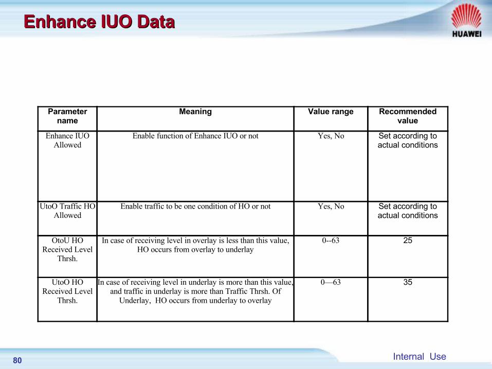
Enhance IUO DataEnhance IUO Data
Parameter name
Meaning Value range Recommended value
Enhance IUO Allowed
Enable function of Enhance IUO or not Yes, No Set according to actual conditions
UtoO Traffic HO Allowed
Enable traffic to be one condition of HO or not Yes, No Set according to actual conditions
OtoU HO Received Level
Thrsh.
In case of receiving level in overlay is less than this value, HO occurs from overlay to underlay
0--63 25
UtoO HO Received Level
Thrsh.
In case of receiving level in underlay is more than this value, and traffic in underlay is more than Traffic Thrsh. Of
Underlay, HO occurs from underlay to overlay
0—63 35
81 Internal Use
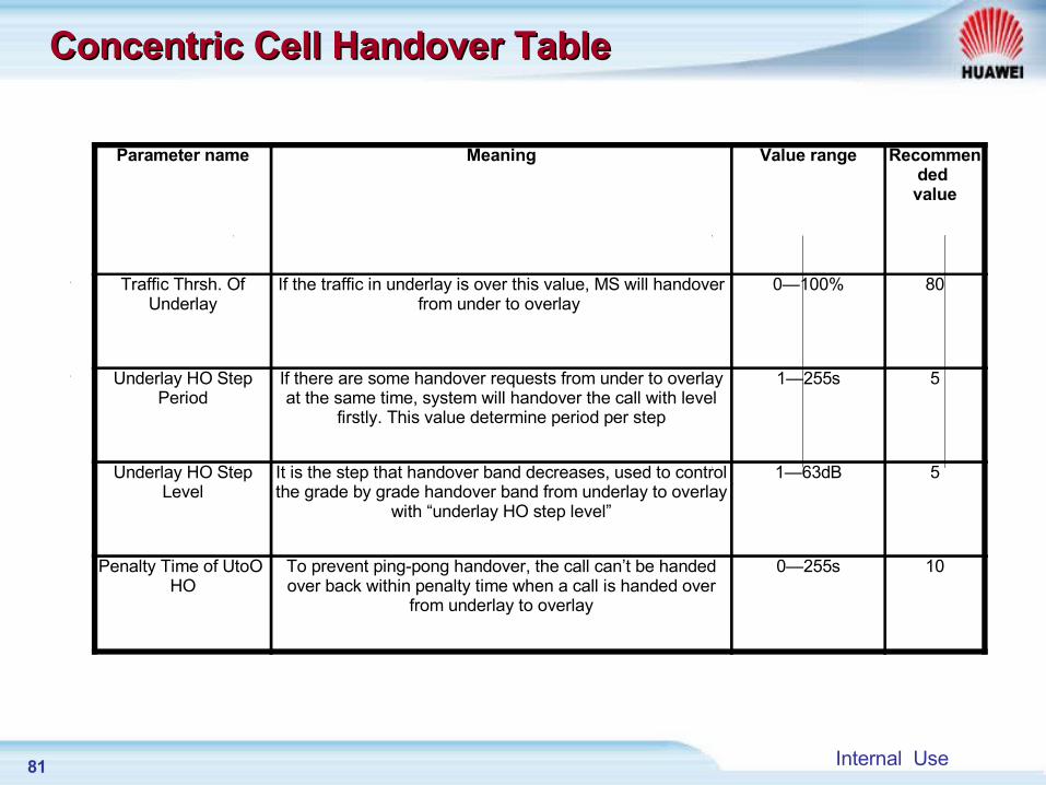
Concentric Cell Handover TableConcentric Cell Handover Table
Parameter name Meaning Value range Recommended value
Traffic Thrsh. Of Underlay
If the traffic in underlay is over this value, MS will handover from under to overlay
0—100% 80
Underlay HO Step Period
If there are some handover requests from under to overlay at the same time, system will handover the call with level
firstly. This value determine period per step
1—255s 5
Underlay HO Step Level
It is the step that handover band decreases, used to control the grade by grade handover band from underlay to overlay
with “underlay HO step level”
1—63dB 5
Penalty Time of UtoO HO
To prevent ping-pong handover, the call can’t be handed over back within penalty time when a call is handed over
from underlay to overlay
0—255s 10
82 Internal Use
HO data lookup process HO data lookup process
BA2 table defines BCCH frequencies of all neighbor cells. It is sent to MS by system message 5, system message 5-bis and system message 5ter on SACCH channel.
MS reports the serving cell and BCCH, BSIC and signal levels of 6 strongest neighbor cells to BSS. This is done through SACCH.
MR pre-process is done in BTS. Module number, cell number and CGI of all neighbor cells are derived from Adjacent cell Relation Table, and Cell Description Table (or External Cell Description Table) through BCCH and BSIC in the MR.
83 Internal Use
HO data lookup processHO data lookup process
BSC performs HO judgment process, such as basic rank of cells (completed in LAPD board). When BSC finds suitable target, It sends HO request messages containing the target CGI to MPU of BSC. According to CGI, MPU derive the module number of the cell from Cell Module Information Table.
MPU sends a HO command message to the target module and step up the ‘inter-cell/ intra-cell HO request’ counter by one.
84 Internal Use
Chapter 1 Introduction of Handover
Chapter 2 HO Algorithm process
Chapter 3 HO Data Configuration
Chapter 4 Chapter 4 HO Signaling processHO Signaling process
85 Internal Use
Chapter 4 Chapter 4 HO Signaling processHO Signaling process
Section 1 Intra BSC Handover
Section 2 Intra MSC Handover
Section 3 Inter MSC Handover
86 Internal Use
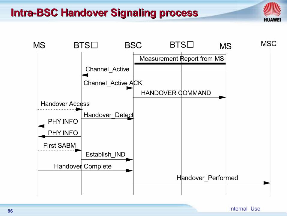
Intra-BSC Handover Signaling processIntra-BSC Handover Signaling process
MS MSBTS BTSBSC MSC
Measurement Report from MS
Channel_Active
Channel_Active ACK
HANDOVER COMMAND
Handover Access
Handover_DetectPHY INFO
First SABMEstablish_IND
PHY INFO
Handover Complete
Handover_Performed
87 Internal Use
Intra-BSC Handover Signaling processIntra-BSC Handover Signaling process
Attention In asynchronous HO, if MS could not reach the new TCH
channel after the target cell has sent PHY INFO up to max times, the target cell reports CONN FAIL IND to BSC with the reason: HO access failure.
After the above message is received, BSC release the assigned TCH channel in the target cell .
Max resend times of physical information*Radio link connection timer > Time interval between EST IND and HO DETECT (120~180ms). This is to make sure that the physical information reach MS.
88 Internal Use
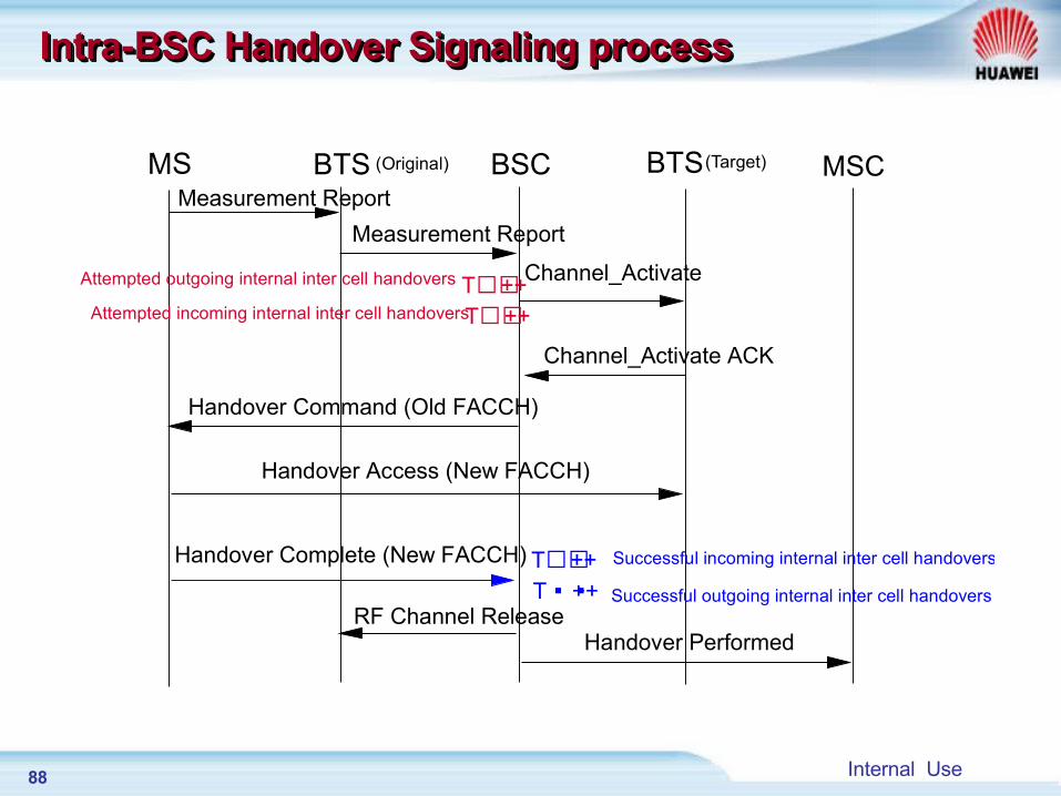
MS BTS BTSBSC MSCMeasurement Report
Measurement Report
Channel_Activate
Channel_Activate ACK
Handover Command (Old FACCH)
Handover Access (New FACCH)
Handover Complete (New FACCH)
RF Channel ReleaseHandover Performed
T ++T ++
T ++T ++
Attempted outgoing internal inter cell handovers
Attempted incoming internal inter cell handovers
Successful incoming internal inter cell handovers
Successful outgoing internal inter cell handovers
(Original) (Target)
Intra-BSC Handover Signaling processIntra-BSC Handover Signaling processIntra-BSC Handover Signaling processIntra-BSC Handover Signaling process
89 Internal Use
Measurement Points of Intra BSC HandoverMeasurement Points of Intra BSC Handover
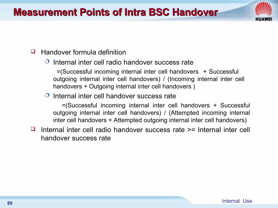
Handover formula definition Internal inter cell radio handover success rate =(Successful incoming internal inter cell handovers + Successful
outgoing internal inter cell handovers) / (Incoming internal inter cell handovers + Outgoing internal inter cell handovers )
Internal inter cell handover success rate =(Successful incoming internal inter cell handovers + Successful
outgoing internal inter cell handovers) / (Attempted incoming internal inter cell handovers + Attempted outgoing internal inter cell handovers)
Internal inter cell radio handover success rate >= Internal inter cell handover success rate

90 Internal Use
Chapter 4 Chapter 4 HO Signaling processHO Signaling process
Section 1 Intra BSC Handover
Section 2 Intra MSC Handover
Section 3 Inter MSC Handover
91 Internal Use
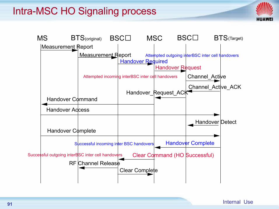
MS BTS BTSBSC BSCMSC(original) (Target)
Measurement Report
Measurement ReportHandover Required
Handover Request
Channel_Active
Channel_Active_ACKHandover_Request_ACK
Handover Command
Handover Access
Handover Detect
Handover Complete
Handover Complete
Clear Command (HO Successful)
RF Channel ReleaseClear Complete
Attempted outgoing interBSC inter cell handovers
Attempted incoming interBSC inter cell handovers
Successful incoming inter BSC handovers
Successful outgoing interBSC inter cell handovers
Intra-MSC HO Signaling processIntra-MSC HO Signaling process
92 Internal Use
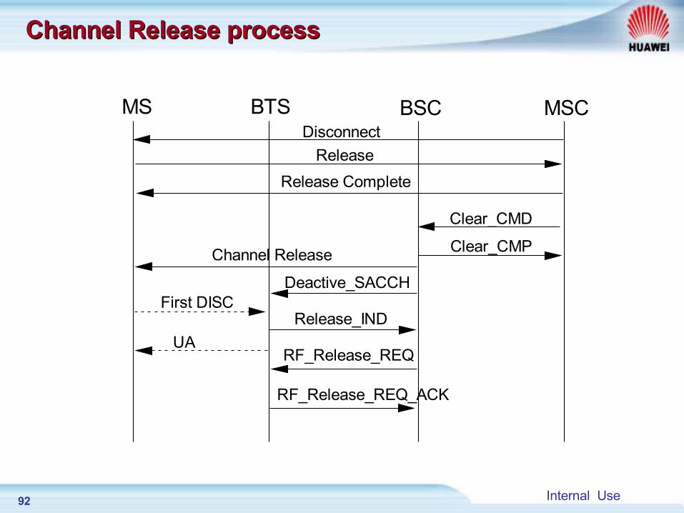
Channel Release processChannel Release process
MS BTS BSC MSCDisconnect
Release
Release Complete
Clear_CMD
Clear_CMPChannel Release
Deactive_SACCHFirst DISC
UA
Release_IND
RF_Release_REQ
RF_Release_REQ_ACK
93 Internal Use
Chapter 4 Chapter 4 HO Signaling processHO Signaling process
Section 1 Intra BSC Handover
Section 2 Intra MSC Handover
Section 3 Inter MSC Handover
94 Internal Use
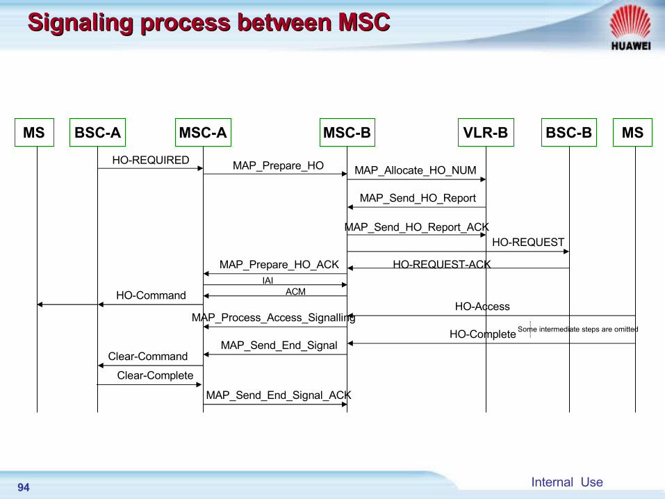
MSC-BMSC-A VLR-BBSC-A BSC-B
HO-REQUIRED MAP_Prepare_HO
MAP_Prepare_HO_ACK
MAP_Allocate_HO_NUM
MAP_Send_HO_Report
MAP_Send_HO_Report_ACK
MS
HO-REQUEST
HO-REQUEST-ACK
HO-Command
MS
HO-AccessMAP_Process_Access_Signalling
HO-CompleteMAP_Send_End_Signal
Clear-Command
Clear-Complete
MAP_Send_End_Signal_ACK
Some intermediate steps are omitted
IAIACM
Signaling process between MSCSignaling process between MSC
95 Internal Use
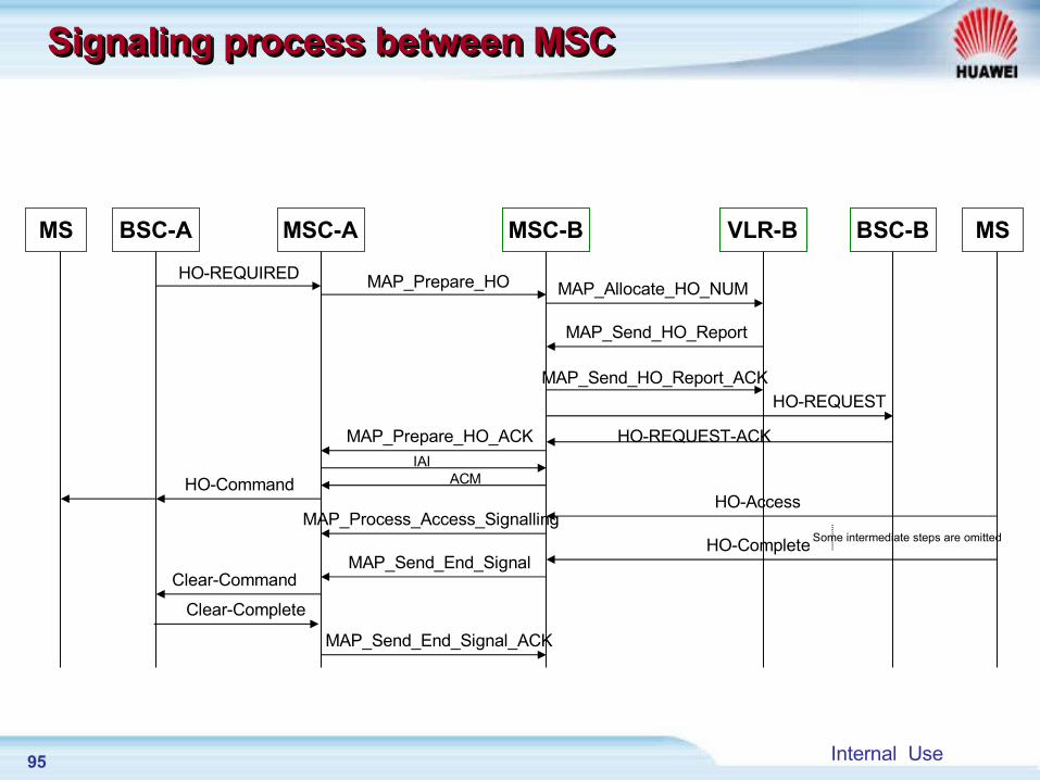
MSC-BMSC-A VLR-BBSC-A BSC-B
HO-REQUIRED MAP_Prepare_HO
MAP_Prepare_HO_ACK
MAP_Allocate_HO_NUM
MAP_Send_HO_Report
MAP_Send_HO_Report_ACK
MS
HO-REQUEST
HO-REQUEST-ACK
HO-Command
MS
HO-AccessMAP_Process_Access_Signalling
HO-CompleteMAP_Send_End_Signal
Clear-Command
Clear-Complete
MAP_Send_End_Signal_ACK
Some intermediate steps are omitted
IAIACM
Signaling process between MSCSignaling process between MSCSignaling process between MSCSignaling process between MSC
96 Internal Use
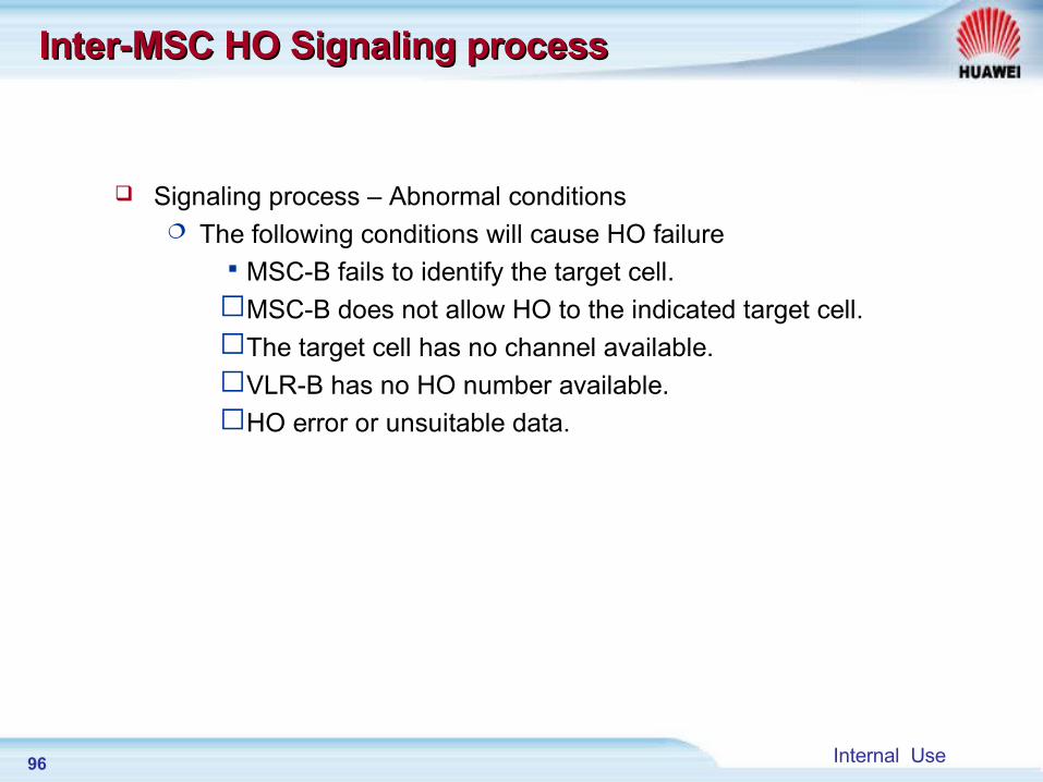
Inter-MSC HO Signaling processInter-MSC HO Signaling process
Signaling process – Abnormal conditions The following conditions will cause HO failureMSC-B fails to identify the target cell.MSC-B does not allow HO to the indicated target cell.The target cell has no channel available.VLR-B has no HO number available.HO error or unsuitable data.
97 Internal Use
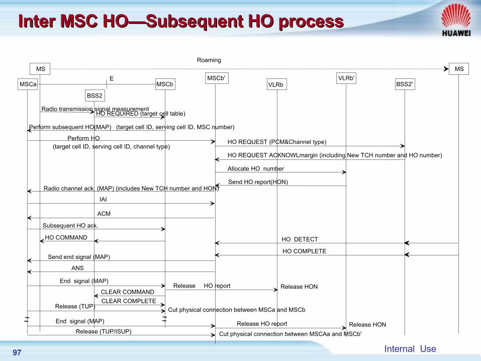
Roaming
E
MS
MSCa MSCbMSCb'
VLRbVLRb'
BSS2
BSS2'
Radio transmission signal measurementHO REQUIRED (target cell table)
Perform subsequent HO(MAP) (target cell ID, serving cell ID, MSC number)
Perform HO(target cell ID, serving cell ID, channel type)
HO REQUEST (PCM&Channel type)
HO REQUEST ACKNOWLmargin (including New TCH number and HO number)
Allocate HO number
Send HO report(HON)Radio channel ack. (MAP) (includes New TCH number and HON)
IAI
ACM
Subsequent HO ack.
HO COMMAND HO DETECT
HO COMPLETESend end signal (MAP)
ANS
End signal (MAP)Release HO report Release HON
CLEAR COMMAND
CLEAR COMPLETERelease (TUP)
Cut physical connection between MSCa and MSCb
End signal (MAP)
Release (TUP/ISUP)Release HO report Release HON
Cut physical connection between MSCAa and MSCb'
~~ ~~
MS
Inter MSC HO—Subsequent HO processInter MSC HO—Subsequent HO process
98 Internal Use
Highway
MSC-AMSC-C
MSC-B MSC-C
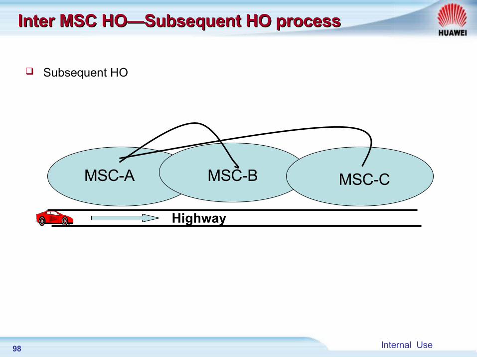
Inter MSC HO—Subsequent HO processInter MSC HO—Subsequent HO process
Subsequent HO
99 Internal Use
Inter MSC HO Signaling processInter MSC HO Signaling process
Statistics counter—same as Intra MSC HO, Statistics is handled by BSC
HO formula-- same as Intra MSC HO
100 Internal Use
Major differences Major differences
There is no “HO request” information for intra-BSC HO, and all of the HO are analyzed and processed in BSC. Once the target cell as required is found in the BSC, “Channel activation” information is sent to it directly.
When the target cell is not in the same BSC, BSC reports CGI numbers of the serving cell and target cell, and HO cause to MSC through “Ho-Required”. When MSC finds the LAC of the target cell is in the MSC, it sends “Ho-Request” to the BSC of the target cell, and the target BSC activates the target cell channel to complete the following procedure.
When MSC finds that the target cell LAC does not belong to the MSC, it will query its “LAI and GCI Table” (including LAC and router address of the adjacent MSC), and send “Prepare-HO” message to the target MSC-B according to the router address. The message includes CGI of the target cell and indication whether or not to allocate HO number, etc. According to the message, the target MSC-B sends “HO-Request” message to the target BSC-B after demanding HO number (unless it is not required in the indication) from VLR-B, and sends “Prepare-HO acknowledgement” to serving MSC after received “HO-Request acknowledgement”, to execute the next procedure.
101 Internal Use
Major differencesMajor differences
Inter BSC HO transfers “HO-REQ” message through MSC, with CGI of the serving cell and target cell carried in the message.
Intra BSC HO does not have any CGI in any messages, it is handled inside BSC.
Intra BSC HO only sends “HO-Performed” to MSC upon completion of HO, and MSC is not involved before that time.
In inter BSC HO, MSC is involved since the HO request .
102 Internal Use
SummarySummary
In this course, we have learned: Classify of handover Judgment and Ranking step Handover Data Configuration Handover signaling Flow
SummarySummary

Huawei Confidential. All Rights Reserved