trussed rafter - holden timber
TRANSCRIPT

Trussed RafterTechnical Manual
CI SfB(27.9) Xi2
May 2003

Contents1 Introduction2 Technical data3 Common trussed rafter shapes4 Truss loadings5 Typical eaves details6 Attic trusses7 Common roof shapes8 Flat top hip9 Overlaid hip10 Typical L return11 T-intersection12 Dogleg intersection
13 Handling and storage14 Arrangement of roofing styles
Some structural features explained
16 Standard stability bracingMono-pitch trussed rafters
17 Standard stability bracingDuo-pitch trussed rafters
18 Gable ladders, hatches andchimneysRecommended preparation
19 Water tanksRecommended preparation
Your Constructive Partner
Wolf Systems was formed in 1988 as an integral part of the Austrian basedJohann Wolf Group’s expansion into the world roof truss systems market,offering an innovative package including:
� Market leading, user-friendly software� Long-term fair pricing� New standards of customer service
The development of sophisticated design and technical facilities has placed Wolfin a commanding position amongst its competitors. This is largely due to ouradvanced timber roof design, manufacturing and management software. Allsoftware is user-friendly and very stable allowing detailed working drawings to beproduced easily.
Wolf Systems have now added their expertise and knowledge into otherproducts and services, which compliment trussed rafters. These include our easi-joist metal web floor system and KeyBuild Timber frame software, which ismarketed through our Keymark subsidiary. We support clients with that specialdegree of flexibility and innovation that has characterised our success.
Mission Statement
Our mission is to assist customers in achieving industry-leading status. We willprovide the most advanced software and efficient nailplate products backed byrelevant design services, machinery and other assistance. Wolf Systems will beconsistently ethical in applying technical and industry standards and maintainexemplary quality at all times.
20 Fixings: anchorage, wallplate positions, care in preparationApplication details
21 Fixings: straps and clipsApplication details
22 Fixings: shoes and hangersApplication details
23 Ventilation and insulationRecommended construction
24 Glossary of terms28 Information required

TRUSSED RAFTERS have proved to be an efficient, safe and economical method for supporting roofs since theirintroduction into the UK in 1964. They are manufacturedby specialised timber engineering companies, who supplyto all sections of the construction industry. Developmentshave been extensive, and today complex roofscapes areeasily formed with computer designed trussed rafters.
With the continuing trend toward individualism indomestic house styling, let alone the reflection of this innew inner city estates, the facility to introduce variationsto the standard designs is vital. The provision of manycharacter differences by designing and then constructing L returns, doglegs and hips for example, satisfies theinherent need for individuality at affordable prices.
Economical roofing solutions for many commercial,industrial and agricultural buildings; hospitals, armybarracks and supermarket complexes, are achieved by theexpeditious installation of trussed rafters.
Experienced roof designers and trussed rafter manu-facturers are therefore in an ideal position to assist thearchitect or specifier in achieving affordable solutionsthroughout the building industry. Simply provide a briefsketch or description of that being considered, includingalternatives, and we will do the rest. The whole roof isdesigned and specified using state-of-the-art computeraided technology supplied by Wolf Systems. We can alsoarrange for one of our specialists to visit and advise you.
This technical manual highlights some of the basicstructural arrangements and assembly information youmay require. In addition, we can offer technical expertiseand experience in a comprehensive advisory service toclients, from initial sketch to completed trussed rafters.
1

Technical Data
NailplatesWe use and recommend Wolf 100 nailplates which are precision punched 1mm gauge metalplates with integral teeth and are manufactured fromstructural grade galvanised mild steel to BS 10147 Fe E 220 G275. They carry a 60 year performance warrantyand are covered by CertificateNo.89/2290 issued by the British Board of Agrément.
Also available and often specified for spliced timberjoints, are the Wolf 125 nailplates in 1.25mmgalvanised mild steel.
1.5mm gauge nailplates, imported from Austria, are available for heavier timber constructionsrequiring longer teeth. They are supplied in limitedpre-determined sizes. Wolf 15N are galvanised: Wolf 15NE are stainless steel for specific applications only.
DesignTrusses are designed in accordance withthe current Code of Practice, which is BS 5268: Part 3, and the relevant BuildingRegulations.
SpansStandard trusses can be designed up to 11 metres in 35mm timber, and 15 metresin 47mm timber. Spans in excess of thesecan be designed but are often supplied asmultiple trusses fixed together.
PitchesIt is more economical to standardise therange of pitches between 15 & 40 degrees,however, trusses may be supplied outsidethis range. Care should be taken whenspecifying because deflection problemsmay arise with eg. very shallow pitches.
Eaves OverhangsAny overhang can be supplied to suit thecustomer's requirements. NB. Very largeoverhangs may cause the trusses to beuneconomical.
SpacingTrusses are usually spaced at 600mm, butcan also be positioned at 450mm or 400mmto support heavier loads.
TimberWe use timber which is kiln dried andstress graded, and which complies with current European and British Standards.
PreservationTrusses may be treated with one of the newwaterborne solutions, or with non-corrosive spirit-based organic solvents.Copper Chrome Arsenate and similartreatments, are not recommended.
2

3
Some common trussed rafter shapesKING POST
FINK
FAN
CANTILEVER
RAISED TIE FLAT TOP (HIP END)
MONO 2/1 SCISSOR
MONO 2/2 ATTIC
MONO 3/2 PARALLEL
QUEEN POST
HOWE
DOUBLE W
BOBTAIL/STUB END

4
Truss Loadings
RAFTER LOADSLong Term Loads: For standard concreteinterlocking tiles the loads are as follows:
Tile weight 575 N/m2
Truss self weight 75 N/m2
Battens & felt 35 N/m2
685 N/m2
Where a rafter bay forms part of the room (inraised tie and attic trusses) an additional loadof 250 N/m2 is added for the ceiling finishes.
Medium Term Loads: For small buildings ie.total floor area less than 200m2 and where roofshape calculations have not been made, the0 - 30 degrees site snow load is 750 N/m2. Thisreduces for pitches greater than 30 degrees,reducing to zero at 60 degrees.
Short Term Loads: A man point load of 675 N(900 N x 75% for load sharing) is applied torafters up to 30 degrees. However, experiencehas shown that for standard truss configurationsdesigned for 750 N/m2 snow loads, the rafterman point load is not a critical load case.
Wind Loads: Wind loads are calculated inaccordance with CP3: Chapter V part 2, allstructures are assumed to be of Class B.
CEILING TIE LOADSLong Term Loads: These are as follows:
Truss self weight 75 N/m2
Plaster board 175 N/m2
Imposed load (loft storage) 250 N/m2
Total long term load 500 N/m2
Tank load at 2 node points normally 450 N pernode (see tank details on page 19).
Short Term Loads: A man point load of 675 N(900 N x 75% for load sharing) is applied at apoint likely to produce the highest stress in theceiling tie.
ADDITIONAL LONG TERM LOADS FORATTIC TRUSSESThe floor area will be loaded as follows:
Domestic imposed load 1500 N/m2
Partition loads 250 N/m2
Truss self weight 75 N/m2
Plaster board 175 N/m2
Floor boarding 250 N/m2
2250 N/m2
Point loads are applied to the nodes at the sideof the room for the plaster board of 250 N/m2. xheight at the side of the room. A load of250 N/m2 is applied to rafters where they formpart of the room.
Imposed loads in accordance with BS 6399.
WolfChord Composite Beams
WolfChord Composite Beams generallyconsist of two timbers plated together toform a deeper section. The method offixing is to cut away the lower memberso that it rests on the wallplate. It shouldbe secured to wallplates by using eitherglide shoes or truss clips.
Nailplates used to secure the twotimber members together are evenlydistributed over the length.

5
Typical eaves details
Standard eaves joint
Horn detail built into wall
French heel
Blocked heel
Relief rafter Cantilever
Scissors
Raised Tie
Cladding to vertical face
Hanger detail(see page 22)
Diagonalbracing mustbe used
15° minimum
Maximum Birdsmouth = 1/3rd rafter depth
30° minimum
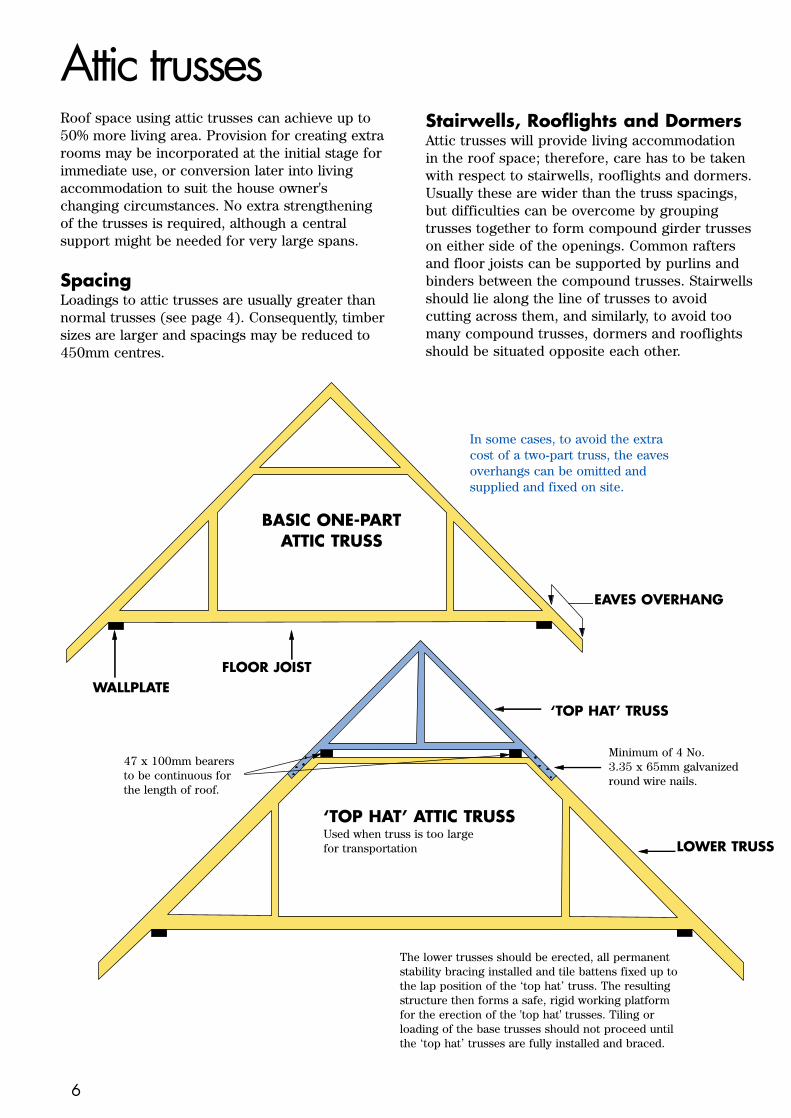
Attic trussesRoof space using attic trusses can achieve up to50% more living area. Provision for creating extrarooms may be incorporated at the initial stage forimmediate use, or conversion later into livingaccommodation to suit the house owner'schanging circumstances. No extra strengtheningof the trusses is required, although a centralsupport might be needed for very large spans.
SpacingLoadings to attic trusses are usually greater thannormal trusses (see page 4). Consequently, timbersizes are larger and spacings may be reduced to450mm centres.
Stairwells, Rooflights and DormersAttic trusses will provide living accommodation in the roof space; therefore, care has to be takenwith respect to stairwells, rooflights and dormers.Usually these are wider than the truss spacings,but difficulties can be overcome by groupingtrusses together to form compound girder trusseson either side of the openings. Common raftersand floor joists can be supported by purlins andbinders between the compound trusses. Stairwellsshould lie along the line of trusses to avoidcutting across them, and similarly, to avoid toomany compound trusses, dormers and rooflightsshould be situated opposite each other.
In some cases, to avoid the extracost of a two-part truss, the eavesoverhangs can be omitted andsupplied and fixed on site.
Minimum of 4 No. 3.35 x 65mm galvanizedround wire nails.
‘TOP HAT’ TRUSS
The lower trusses should be erected, all permanentstability bracing installed and tile battens fixed up tothe lap position of the ‘top hat’ truss. The resultingstructure then forms a safe, rigid working platformfor the erection of the 'top hat' trusses. Tiling orloading of the base trusses should not proceed untilthe ‘top hat’ trusses are fully installed and braced.
47 x 100mm bearersto be continuous forthe length of roof.
WALLPLATEFLOOR JOIST
EAVES OVERHANG
LOWER TRUSS
BASIC ONE-PARTATTIC TRUSS
‘TOP HAT’ ATTIC TRUSSUsed when truss is too large for transportation
6

7
Common roof shapes
Mono-pitch
Hipped
Mono L return
Dormer
Duo-pitch
Dutch or Barn hip
Mono L return/Mono hip
Dogleg
L return
Gablet
Overlaid hip
T-intersection

Flat top hip
J4
J4
J3
J3
J2
J2
J1
J1
T3
T2
T2
T2
T1
T1
T1
T3 T3 T3 T3 T3 T3
REF: FLAT TOP HIPDESIGNED BY:
SITE:PLAN SCALE:
Truss 1 : 3 off
Truss 2 : 2x1ply & 1x2 ply
T = TrussJ = Jack Rafter
Truss 3 : 7 off
8
The horizontal top chords to the flat top trusses are to be well bracedtogether to resist lateral buckling
Infill Jack Rafters
to be a minimum of 25mmdeeper than trussed raftermembers to allow forbirdmouthing at wallplate
Mono Pitch Trusses
supplied with extendedrafters for site cuttingto suit hip boards
Noggings to be nailed to ceiling joist and side of jack rafter
Compound Girder
of Flat Top Trusses
permanently fixedtogether
Standard
Trusses to
Main Roof
Flat Top Trusses
supplied with extendedrafters for site cutting tosuit hip boards
Hip Boards to be birdmouthed over the compound girder of flat toptrusses and over the wallplate
Infill Ceiling Joists

Overlaid hip
REF: OVERLAID HIP DESIGNED BY:
SITE:PLAN SCALE:
T2
T3 T3
T3
T3
T1
T1
T1
T1
T1
T1
T1
T1
T1
T1
T3
T3 T3
Truss 3 : 7 off
Truss 2 : 1x3 ply
Truss 1 : 10 off
9
Standard Trusses
with overhangremoved on one side
Standard Trusses
to Main Roof
Standard
Trusses to
Main Roof
Compound Girder of
three Flat Top Trusses
permanently fixed together
Hip Boards to be birdmouthedover compound girder of flat toptrusses and over wallplate
Set of four Valley Frames
including two special flat topframes purpose made tospread imposed load
Valley frames are designed totransfer the tile loading uniformlyto the top chords of the underlyingtrusses, and should be used in allcases rather than constructing thisarea with common infill timber.

Typical L return
J3
J3
J2
J2
J1
J1
T3
T2
T2
T2
T1
T1
T1
T1
T1
T3 T3 T3 T3 T3 T3 T3 T3 T4 T5 T5 T5
REF: TYPICAL L RETURNDESIGNED BY:
SITE:PLAN SCALE:
Truss 1 : 5 off
Truss 2 : 2x1 ply & 1x2 ply
Truss 4 : 1x3 ply
Truss 3 : 9 off
T = TrussJ = Jack Rafter
Truss 5 : 3 off
10
Compound Girder
of three Trusses
permanently fixedtogether
Lateral Bracing
Ridgeboard
Compound Girder of
two Flat Top Trusses
permanently fixedtogether
Set of four Mono
Valley Frames
the smallest isomitted for clarity

T-intersection
Standard Trusses to Main Roof
Standard Trusses
with overhang removedon one side
Set of three diminishing
Valley Frames naileddirectly on to the maintrussed rafters. Theinternal members of thevalley frames are omittedfor the sake of clarity
If a load-bearing wall or beam isavailable between position A-A
to support the standard trusses onthe main roof, then the compound of howe girder trusses can besubstituted by a standard truss on the return roof
Valley frames are designed totransfer the tile loading uniformlyto the top chords of the underlyingtrusses, and should be used in allcases rather than constructing thisarea with common infill timber.
REF: T - INTERSECTIONDESIGNED BY:
SITE:PLAN SCALE:
T2
T1 T1T1 T1T1T1 T1 T1 T1 T1
Truss 1 : 10 off
Truss 2 : 1x2 ply
Compound Girder of two
Howe Trusses permanentlyfixed together
A
A
11

Dogleg intersection
Type 2 Type 1
REF: DOGLEG INTERSECTION DESIGNED BY:
SITE:PLAN SCALE:
T3
T1T1
T2
J1
J2
J3
J4
J5J6
C6 C5 C4 C3 C2 C1 T2 T1 T1
Truss 1 : 4 off
Truss 2 : 2x2 ply
T = TrussJ = Jack RafterC = Ceiling Joist
Truss 3 : 1x3 ply
12
Ridgeboard
Support Ledgers
nailed to compoundgirder trusses
Ridgeboard
Standard
Trusses to
Main Roof
Binders
Infill
Ceiling
Joists
The five roofscapes illustrated in thissection are those most commonly
constructed. There are many other waysof framing hips, corners, intersections etc.
with trussed rafters. Please contact us for help and specific details.Purlin Support securely
nailed to internal trussmember. Minimum sizeto be 60mm x width ofcompound truss
Purlin
Compound
Girder Truss
Standard Trusses
to Main Roof
Infill Rafters to be mimimum 25mmdeeper than trussed rafter member to allow for birdmouthing at purlinand at wallplate
Compound Girder Trusses
permanently fixed together

13
Storage and handling on siteHANDLINGThis information shows how trussesmay be handled such that no structuraldamage occurs. It does not infer a safelifting method for site staff whoshould take note of both H.S.E. LiftingRegulations and Construction (Designand Management) Regulations 1994.Mechanical handling for unloading anderecting trusses safely is stronglyrecommended.
Trusses may become damaged by incorrecthandling. During transportation, they may,of necessity, also be inverted. Whenmechanically handled, the trusses shouldbe banded together in sets and supportedwhen lifting utilizing a spreader bar, asshown in fig 2.
TYPICAL TRUSS WEIGHTS
35mm thick fink truss = 35 kg
30°
7.7m span
47mm thick attic truss = 110 kg
40°
8m span
3 ply 35mm thick howe girder = 160 kg
NB: Weights given are for guidance only.For lifting and handling check actual truss weights
30°
9m span
STORAGEIt is imperative to prevent damage ordeformation to trusses awaiting erection.They should be stored as illustrated (3 & 4)and protected from sun and rain. Adequateallowance must be made for ventilation.
Correct Manhandlingnot less than 3 persons
are advised
Mechanical Handlinggood mechanicallifting method
Vertical Storage
Horizontal Storage
1
2
3
4
Spreader bar
Node point
Rope guide
Trestle propTrestle prop
Bearer height to allow overhangto clear ground
Bearers vertically in lineand at close centres

Some structural features explainedThe variation of roofing styles possible withtruss rafters is unlimited. In this illustratedarrangement, we have shown some of themore popular constructions. The applicationof trussed rafters is efficient, safe and economical. Produced by precisionmanufacturing, all structural roofing timbers can be delivered to sitefor immediate erection thus obviating problems with site storage anddeterioration, pilfering and damage. Tiling is often completed thesame week as truss rafter deliveries.
Wolf Systems computer software generates layouts similar to this, as well as full working plan-drawings. Furthermore, the WolfSystem also provides structural calculations andmanufacturing details, as required by Building Controlauthorities.
N.B. In this layout all bracings andfixings, and some timbers havebeen omitted for the sake ofclarity.
TRUSSTO GIRDERCONNECTION
QUEEN POST TRUSSESwith infill around chimney
Arrangement of roofing styles
GABLE LADDERS cut togive 50mm min. clearanceof chimney. They shouldbe nailed directly to the faceof the last positioned truss.
VALLEY SETnecessary to continue roofline at inter-sections, usually indiminishing sets.
ATTIC TRUSSES WITHDORMERS & ROOFLIGHTScan achieve up to 50% moreliving space. Generally trussesare constructed of largersized timbers, and spacingsmay be reduced.
FLAT TOP HIP
DUTCH OR BARN HIP
TRUSS STRAP AT CEILING LEVELNoggings at two metre intervals are required when straps are used. Strap of 30x5mmto span min. 3 trusses

FINK TRUSSES are the most common typeof truss, they are duo-pitched with the webs
forming a letter W. Some of the trussesare cut away to show the water tank
which is mounted on a platformwith support bearers.
EAVES ARRANGEMENT
TRUSS STRAP AT RAFTER LEVELHeavy-duty galvanised strap 30x5mmspanning minimum of 3 trusses
GLIDE SHOE FOR FIXING RAISED TRUSSESTruss to be nailed to shoe only after all dead weights have been imposed
Steel platefastened to trussShoe
securedto wallplate
Wolf Nailplateoverlappingwallplate bya min. 50%
TrussclipWallplate
Fixing batton
Framing anchorOptional tilt fillet
Ventilatedsoffit board
Compound girderof two trusses
RAISED TIE TRUSSESOVER PORCH withincorporated gabble ladder OVERLAID HIP with
set of 3 valley frames andflat top compound girder.
BARGEBOARD to concealroof timbers, is usually securedto timbers at gable ends.
GABLET a vertical roofsection set back fromthe slope of the hip end.
SIMPLIFIED PLAN VIEWOF ROOF LAYOUTShowing the mainfeatures
HIP BOARDS slopingfrom ridge to corner in a hip end construction.
FLAT TOP HIP ENDshowing compoundgirder of two flattop trussespermanently fixedtogether, and twofurther single flattop trusses behind.

Standard stability bracingMONO-PITCHTRUSSED RAFTERS
Bracing for other types of rooftrusses (eg. attic trusses) willrequire a special design. Please contact our design office.
16
Section X-X
Section Y-Y
NOTE: Chevron bracing shown is not required on internal membersof trusses for spans of 5m or less
Diagram 1. Standard bracing for rafter and web members of mono-pitch trussed rafters.
Chevron brace to be atapprox. 45 degrees and nailed to at least 3 trusses.
Alternative direction ofchevron bracing.
Longitudinal bracing memberlap jointed if required.Members to tightly abut everygable and party wall
Section W-W
Longitudinal bracing member
Rafter diagonalbracing
Chevron bracing to webs
Section (showing 3/3 mono truss)
Longitudinalbracing See detail Z
in diagram 2,page 17
Nailed towallplate
Alternative direction of rafter diagonalbracing
Rafter diagonalbracing
W
W
Section (showing 4/3 mono truss)
Section (showing 3/2 mono truss)
For spans in excess of 8m additionalchevron bracing will be required
X
Y
X
Y

Standard stability bracingDUO-PITCHTRUSSED RAFTERS
Bracing for other types of rooftrusses (eg. attic trusses) willrequire a special design. Please contact our design office.
17
Diagram 2. Standard bracing for rafter and web members of duo-pitch trussed rafters.
Longitudinal bracing membersto tightly abut every gable andparty wall
Longitudinal bracing
Trussspan
DetailZ
DetailZ
Trussspan
Chevron bracingto webs
Rafterdiagonalbracing
Rafter diagonal bracing
Alternative direction of rafterdiagonal bracing
Chevron brace to be atapprox. 45 degrees andnailed to at least 3 trusses
Alternative direction ofchevron bracing
Maximum of 2 trussesbetween chevron bracing
Gable ends
Gable ends
Plan of rafter diagonal bracinglayout (narrow fronted roof)
Plan of rafter diagonal bracinglayout (wide fronted roof)
Section (showing fink truss)
Section (showing fan truss)
Section (showing double W truss)
Y
Y X X
Wallplate
Nailed toWallplate
Rafter diagonalbrace lap jointed ifrequired Ideally 45o but not less
than 35o or greaterthan 50o
Detail Z22 x 97 x 600mm longtimber splice plate nailedusing a minimum of 4 No. 3.35mm x 65mm longgalvanised round wire nailseach side driven through and clenched over
Section X-X Section Y-Y
NOTE: Chevron bracing shownis not required on internalmembers of trusses for spansof 8m or less.

Gable ladders, hatchesand chimneysRecommended preparation
18
CHIMNEY DETAIL
All timbers must be at least 50mm clear of the chimney brickwork
HATCH DETAIL
Ridgeboard
Purlin minimum50 x 100mm
Trimmer minimum50 x 100mm
Binder minimum50 x 100mm
Wallplate
Ridge line Trimmer
BinderPurlin
Ridgeboard supportcollar minimum 25 x 75mm
Bargeboards and Soffitsto be nailed directly tothe gable ladder
Gable Ladders to be fixeddirectly to last truss withnails at 400mm centres
Wallplate may be extendedover the gable ladder widthfor added support if required
Jack Rafter 25mm deeper thantrussed rafter and birdmouthedover wallplate
D max. is equal to twicethe design truss spacing lessthe opening width
Jack Ceiling Joist nailed to side of jack rafter, size to match bottom chord of trussed rafter
D
D
D
D
2
1
Hatch and chimney openings:Whenever possible hatch openings should be accommodated within the trussed rafter design spacing. When this is not possible the method illustrated 1 and 2 should be used.
opening
opening

19
Water tanksRecommended preparation
Where tanks are to besupported by trussed rafters,the size, type and position ofthe tanks should be clearlyindicated.
The trusses must bespecifically designed to carrythe extra weight which shouldbe distributed over three ormore trusses by the use ofspreader beams. The loadsshould be applied as close aspossible to the node points onthe ceiling ties. The maximumload imposed by the tank andits contents must not exceed450N at each adjacent ceilingtie node point. In such cases,the support members shouldbe in accordance with thetable below. In other caseswhere applicable, the supportspreader beams should bedesigned to BS 5268: Part 2.
Offset bracing to clear tankbearers (for bracing detailssee pages 16 and 17).
Bearer (a) placed asclose to the node pointas possible.
Bay size
DETAIL A DETAIL B
s = Trussed rafter spacing
Tank
Tank
Trussed rafter span
Tank placedcentrally
Node point
Node point
Node point
ALTERNATIVE SUPPORTBETWEEN MEMBERSWhere space is limited this detailmay be used between members(a) & (b) and (b) & (c) in order togain head room. However aminimum clearance of 25mmabove the ceiling lining should beallowed for possible deflection.
TABLE: SIZES FOR SUPPORT MEMBERS
Total tank capacity to markedwaterline
DETAIL ANot more than 300 Lsupported onfour trussed rafters
DETAIL BNot more than 230 Lsupported onthree trussed rafters
Min. member sizes
a and c b
mm
Max. trussedrafter spanfor finkconfigurationm
Max. baysize for otherconfigurations
m
47 x 72 2/35 x 97 or1/47 x 120 6.50 2.20
47 x 72 2/35 x 120 or1/47 x 145 9.00 2.80
47 x 72 2/35 x 145 12.00 3.80
47 x 72 1/47 x 97 6.50 2.2047 x 72 2/35 x 97 or
1/47 x 120 9.00 2.8047 x 72 2/35 x 120 or
1/47 x 145 12.00 3.80
NOTE: Support members may be of any species with a perissable bending stressnot less than that of European redwood/whitewood of GS or C16 stress grade.

Fixings: anchorage, wallplate positions,care in preparationApplication detailsCareful erection, fixing and strapping is essential
if a trussed rafter roof is to provide a sound platform
for roof coverings and contribute effectively to the
stability of the roof and gable ends.
Strapping gables to ceiling tiesCeiling tie straps may be excluded from the specification if roof pitches are below 20o. Check with the buildingdesigner. If they are needed, fix as shown for truss straps,but attach to upper edge of the ceiling tie. Use a crankedstrap to engage a vertical joint if horizontal courses do not coincide.
Strapping at the separating wallIn addition to the normal strapping to walls, additional straps may have been specified to provide longitudinal bracing between roofs, these should be run over the top of the separating wall and fixed to the specified number of trusses on each side. Include nogging and packing to transmit loads properly.
Position of wallplate
The wallplate should be positionedcentrally on the inner load bearing wall. It is acceptable to move thewallplate a maximum of 20mm tothe left or right of the centre lineof the inner wall.
At least 50% of the nailplate mustoverlap the wallplate and shouldcertainly not oversail by more than 50mm. Do not pack up under ceiling ties. Use a deeper wallplate or adjust where the wall is lower.
Holding down roofs to wallsRoof to wall (vertical) strapping is not requiredunless the location of building construction is known to be wind stressed, then it is essential to carry out the roof designer's specifications. Lighter roof coverings in areas of higher wind load, require holding down straps as may be specified for brick/block construction. In extreme cases, the design may call for direct strapping of rafters to the walls (see illustration).
Straps are normally a minimum 30 x 2.5mm section galvanised steel, but any higher specification should be followed. The tops of straps should be nailed (three 30 x 3.75mm nails or more) to the wall plate, or the rafter in the case of a rafter to wall strap. When fixing to the wall, it is critical that the straps are long enough to run over the specified number of blocks, and that at least two of the fixings engage the last full block at the base of the strap.
•The cavity must be closed along the eaves line,either stopped with masonry or a cavity barrier.
•The wallplate is a minimum of 75mm x 50mm.
•That timber members and nailplates are not damaged.
•That trussed rafters are the correct span andcan be fitted to wallplates without cutting.
•That truss weight information is known.
•That the timber is dry and sound, and thenailplates are free of corrosion.
•That there are no missing nailplates.
•None of the trussed rafters are visibly distorted.
•That there are no unapproved site repairs totrussed rafters. Or that any such repairs havebeen carried out under the direction of thetruss designer.
•That positions for water tank and for chimney,and access openings are all clearly identified.
•That clear guidance is given on the number, size and corrosion resistance of straps, clips and all other fixings.
Nail noggingssecurely to the trusses
Nail the strap to each truss andnogging piece. For clarity thesenails are shown partially driven
Straps to have at least 100mm down-turn, tight against a full block on the gable.
How to fix rafter straps
Checks before erecting trussed rafters
Engage at least three trusses with each strap.Use galvanised steel straps of 30 x 5mm
Pack between endtruss and wall
100mmmin.
Use corrosion-resistant nails (65 x 3.35mm)
20

Fixings: straps and clipsApplication details
21
EHorizontal anchor strap forpitched roof and gable ends
Install straps at a
max. of 2m centres
or as designed
Timber packing
DTwisted andbent horizontalrestraint strap
Truss clips
Truss clips are for fixing timber trusses towallplates. They avoid the damage oftencaused by skew nailing. Two sizes areavailable, and full fasteningstrength can be achieved byusing 30 x 3.75mm squaretwisted sheradised nails through all the holesprovided. Follow themanufacturers'recommendations forsafe application.
Horizontal and vertical restraint straps
All straps are manufactured from galvanisedsteel with holes punched at regular intervalsalong their length. Horizontal straps usuallyhave 30 x 5mm section, and may also feature acombination of bends and edge twists accordingto requirements. Vertical straps have lighterloads and are usually 30 x 2.5mm section.They should all be used in accordance withBuilding Regulations and BS 5268 Part 3.
Wallplate anchor strap
BVertical anchor strapfor trussed rafters.Avoid nailing throughthe nailplate.
CVertical restraint strapfor wallplate anchorage
RESTRAINT
STRAPS
TRUSS
CLIP
E
D
B
A
C

22
Heavy-duty joist hangerto BS6178 Part 1These are generally used to carry trusses or joists at masonry load bearing or fire break walls wherecareful consideration must always be given to themethod of support. We would recommend that adviceis obtained from the responsible Building Designeror Structural Engineer since in a number of casesspecial hangers may have to be manufactured. TheBuilding Designer may also specify high densitybrick courses above and below the hangers to avoidcrushing of blocks. The bearing length for these joisthangers is approx. 90mm.
Heavy-duty girder togirder truss shoesThese are designed to support a secondary girder off the main girder ensuring that the loads are transferred efficiently. The shoe is usually fixed to the main girder (A) by means of 20mm bolts with washers under the bolt heads and nuts. The bearing length for these shoes is approx. 120mm. NB. refer to manufacturers instructions for the correct application and procedure.
Girder truss shoe andlong legged hangersGirder truss shoes are used to fix single trusses tocompound girders or for other truss to trussconnections. The bearing length is approx. 95mm.
When the girder chord supporting the shoe or hanger is less than the length of its side flanges, then a block must be introduced as shown (C) to prevent buckling. Long legged joist hangers (D) are used for timber to timber, or timber to truss connections. They are notsuitable for truss to truss connections, and shouldNEVER be used for this purpose. The bearing lengthis up to 50mm.
Metal fixings used in timber roof structures should have safe working loads which can be substantiated by freely available technical reports in accordance with BS 6178 and TRADA recommendations. They
should always have a manufacturer’s mark and
show the certified safe working load.
It is strongly recommended that timber to timber fixings and timber to brick fixings should be supplied by the Roof Truss Fabricator, and delivered to site with the trusses.
Wolf Nailplates
Approx. 120mm
Not exceeding 50mm
Approx. 90mm
A
B
C
D
Fixings: shoes and hangersApplication details
Incoming trusses (B) supported by heavy
duty shoes and hangers, should be notched
to provide a smooth ceiling line.
N.B. For all the hangers and shoes described
above, every fixing hole requires either a
30 x 3.75mm square twisted sheradised nail,
or a 20mm bolt.
Hanger withreturn flangeto hook overmasonry walls,beams and lintels
Face fixinghanger
Standard hangerfor building into brick or block walls
Straddle hangerfor supportingjoists on eitherside of a wallor beam

Ventilation and insulationConstruction detailsWhen warm, moist air comes into contact with cold surfaces, condensation occurs. Because of the changes in house design, central heatingand some of the building materials used, roofspaces have a tendency to become colder and less ventilated. This has resulted in an increase in water vapour in them. The problem is that trussed rafters do not behave well under damp conditions, and there is a danger that after a prolonged period in these conditions the timberstrength will reduce, rot will be encouraged in the members and the nailplates could be adversely affected.
In order to reduce water vapour in the roof
space, two methods can be employed.
Firstly, to remove water vapour which has gained access to the roof space, there must beadequate ventilation. Useful information canbe obtained from the current issue of BS 5250:The Control of Condensation in Dwellings. For all roofs above 15 degree pitch, ventilation openings equivalent to a continuous opening of10mm should be provided along two opposite sides of the roof. Below 15 degrees this figure should be 25mm. Thermal insulation should be laid above ceilings to ensure that thetemperature is maintained above dewpoint
at ceiling level. Although the insulation should be laid right up to the eaves, a gap should be left to ensure that free flow of air is not hindered. This can be achieved by an insulation overlay tray. It is possible to permit a certain amount of extra ventilation if the felting or tile underlays are permeable to water vapour or laid such that vapour can pass through the joints.
Secondly, a continuous vapour barrier should be fixed to ceiling level beneath the insulation to prevent water vapour entering the roof through the ceiling of the upper floor. At the same time, all access hatches, pipe and ceiling light holes should be sealed with a suitable filler. Wall head cavities should be closed to prevent water vapour entering either through the inner leaf or by evaporation of rain water through the outer leaf. All water tanks and holes through which pipes pass, should be covered and sealed. This procedure is particularly recommended for indoor swimming pools, saunas, etc.
Wolf Nailplate
Roof insulation materials, fixedto the top surface of rafters, that is between tiling battens andtrusses, are not recommended.
Roof space ventilator
Eaves soffit ventilator
Optional tilt fillet
Felting orTile underlay
23

APEX/PEAKThe uppermost point of a TRUSS.
ATTIC TRUSS/ROOM-IN-THE-ROOFA truss which forms the top storey of adwelling, but allows the area to be habitableby leaving it free of internal WEB members.This will be compensated by larger timbersizes elsewhere (see page 10).
BARGEBOARDBoard fitted to conceal rooftimbers at GABLE END.
BATTENSSmall timber members spanning overtrusses to support tiles, slates, etc.
BEARERA member designed to distribute loads overa number of trusses.
BEARINGThe part of a truss receiving structuralsupport. This is usually a WALLPLATE but canbe an internal wall etc.
BINDERA longitudinal member nailed to trusses tomaintain correct spacing.
BIRDSMOUTHA notch in the underside of a RAFTER toallow a horizontal seating at the point ofsupport (usually used with RAISED TIE
TRUSSES - see page 9).
BLOCKINGShort timbers fixed between chords tolaterally brace them. They should be at least70% of the depth of the CHORDS.
BOBTAILA truss type formed by truncating a normaltriangular truss.
BOTTOM CHORDSee CEILING TIE.
BRACINGThis can be Temporary, Stability or WindBracing which are described under theseheadings.
BUILDING DESIGNERThe person responsible for the structuralstability and integrity of the building as awhole.
CAMBERAn upward vertical displacement built into atruss in order to compensate for deflectionwhich might be caused by the loadings.
CANTILEVERThe part of a structural member or TRUSS
which extends beyond its bearing.
CEILING TIEThe lowest member of a truss, usuallyhorizontal which carries the ceilingconstruction, storage loads and water tank.
CHEVRON BRACINGDiagonal bracing nailed to the truss in theplane of the specified webs to add stability.
CHORDSRefer to the Top and Bottom Chords whichare respectively the RAFTER and CEILING TIE.
CONCENTRATED LOADA load applied at a point.
CONNECTOR PLATE/FASTENERSee NAILPLATE.
CRIPPLE RAFTERSee JACK RAFTER.
DEAD LOADThe load produced by the fabric of thebuilding, always long term, (see DESIGN
LOADS).
DEFLECTIONThe deformation caused by the loads.
DESIGN LOADSThe loads for which the unit is designed.These consider the duration of the loads –long term, medium term, short term andvery short term.
DUO/DUAL PITCH TRUSSA truss with two rafters meeting at the APEX
but not necessarily having the same PITCH
on both sides.
DWANGSSee NOGGINGS.
EAVESThe line where the rafter meets the wall.
EAVES JOINT/HEELThe part of the truss where the rafter andthe ceiling tie intersect. This is usuallywhere the truss is supported.
Glossary of terms
24

EXTENDED RAFTERSee RAISED TIE TRUSS.
FASCIAHorizontal board fitted along the length of thebuilding to the edge of the truss overhangs.
FASTENERSee NAILPLATE.
FINK TRUSSThe most common type of truss used fordwellings. It is duo-pitch, the rafters havingthe same pitch. The webs form a letter W.
FIRRING PIECEA tapered timber member used to give a fallto flat roof areas.
FRENCH HEELAn EAVES joint where the rafter sits on theceiling tie.
GABLE ENDThe end wall which is parallel to the trussesand which extends upwards vertically to therafters.
GABLE LADDERComponents used to form an overhang at thegable end.
GIRDER TRUSSA truss made up of two or more fixedtogether and designed to take exceptionalloads, such as those imposed by othertrusses fixed to it.
HEELSee EAVES JOINT.
HIP BOARDA member sloping from ridge to corner in aHIP END construction.
HIP ENDAn alternative to a GABLE END where theend wall finishes at the same height as theadjacent walls. The roof inclines from theend wall, usually (but not always) at thesame PITCH as the main trusses.
HIP SETThe trusses, girders and loose timbersrequired to form a hip end.
HORN/NIBAn extension of the ceiling tie of a truss(usually monos or bobtailed trusses) which isbuilt into masonry as a bearing.
IMPOSED LOADThe load produced by occupancy and useincluding storage, inhabitants, moveablepartitions and snow, but not wind. Can belong, medium or short term.
INTERNAL MEMBERSee WEB.
INTERSECTIONThe area where roofs meet.
JACK RAFTERAn infill rafter completing the roof surface inareas such as corners of HIP ENDS or aroundchimneys.
LIVE LOADTerm sometimes used for IMPOSED LOADS.
LONGITUDINAL BRACINGComponent of STABILITY BRACING.
LOOSE TIMBERTimbers not part of a truss but added toform the roof in areas where trusses cannotbe used.
MONO-PITCH TRUSSA truss in the form of a right-angled trianglewith a single rafter.
NAILPLATEMetal PLATE having integral teeth punchedfrom the plate material. It is used for joiningtimber in one plane with no overlap. It willhave an Agrément Certificate and will bemanufactured, usually, from galvanised steel. It is also available in stainless steel.
NIBSee HORN.
NODEPoint on a truss where the membersintersect.
NOGGINGSTimber pieces fitted at right angles betweenthe rafters and ceiling ties to form fixingpoints.
OVERHANGThe extension of a rafter or ceiling tie of atruss beyond its support or bearing.
Glossary
25

PART PROFILESee BOBTAIL.
PEAKSee APEX.
PERMISSIBLE STRESSESDesign Stresses for grades of timberpublished in BS 5268: Part 2: 1988.
PITCHThe angle of the rafter to the horizontal,measured in degrees.
PLATESee NAILPLATE.
PLATE LOCATION/POSITIONTOLERANCEAcceptable deviation from specified locationfor the plate on a truss. This is usually 5mmbut can be specified greater.
POLE PLATETimber used in cantilevered hips to supportloose timbers.
PURLINSTimber members spanning over trusses tosupport cladding or between trusses tosupport loose timbers.
QUARTER POINTThe point on a rafter where the strutintersects in a FINK TRUSS.
QUEENInternal member (web) which connects theAPEX to a third point on a FINK TRUSS.
RAFTERThe uppermost member of a truss whichnormally carries the roof covering.
RAFTER DIAGONAL BRACINGComponent of STABILITY BRACING.
RAISED TIE TRUSSA truss which is supported at a point on therafter which is beyond the point where therafter meets the ceiling tie.
REDUCING TRUSSESSee VALLEY FRAMES.
REMEDIAL DETAILA modification produced by the TRUSSED
RAFTER DESIGNER to overcome a problemwith the truss after its manufacture.
RETURN SPANThe span of a truss being supported by agirder.
RIDGEThe line formed by the truss apexes.
RIDGEBOARDTimber running along a ridge andsandwiched between loose rafters.
ROOF DESIGNERThe person responsible for the roof structureas a whole, and who takes into account itsstability and capability of transmitting windforces on the roof to suitable load-bearingwalls.
ROOM-IN-THE-ROOFSee ATTIC TRUSS.
SCABAdditional timber fitted to the side of a trussto effect a local reinforcement, particularlyin RAISED TIE TRUSSES.
SETTING-OUT-POINTThe point on a truss where the undersides ofthe rafter and ceiling tie meet.
SKEW NAILINGA method of fixing trusses to the WALLPLATE bydriving nails at an angle through the truss intothe wallplate which is generally notrecommended. (See TRUSS CLIP.)
SOFFITBoard fixed underneath EAVES overhangalong the length of the building to concealtimbers.
SPANSpan over wallplates is the distance betweenthe outside edges of the two supportingwallplates. This is usually the overall lengthof the ceiling tie.
SPANDREL PANELA timber frame, triangular panel forminggable wall above ceiling line.
SPLICEA joint between two members in line using aNAILPLATE or glued finger joint
SPREADER BEAMSee BEARER.
26
Glossary

STABILITY BRACINGAn arrangement of additional timbers fixed inthe roof space to provide lateral support to thetrusses.
STRAPMetal component designed to fix trusses andwallplates to walls.
STRUTInternal member connecting the third pointand the quarter point on a FINK TRUSS.
STUB ENDSee BOBTAIL.
TEMPORARY BRACINGAn arrangement of diagonal loose timbersinstalled for safety during erection. Oftenincorporated with permanent STABILITY andWIND BRACING structures.
THIRD POINTPoint on the ceiling tie where the internalwebs meet in a FINK TRUSS.
TIMBER STRESS GRADINGThe classification of timber into differentstructural qualities based on strength(see BS 4978: 1988).
TOP CHORDSee RAFTER.
TRADA QUALITY ASSURANCE SCHEMEQuality control method in truss manufactureadministered by the Timber Research andDevelopment Association.
TRIMMERA piece of timber used to frame aroundopenings.
TRUSS/TRUSSED RAFTERA lightweight framework, generally but notalways triangulated, placed at intervals of600mm to support the roof. It is made fromtimber members of the same thickness,fastened together in one plane usingnailplates or plywood gussets.
TRUSSED RAFTER DESIGNERThe person responsible for the design of theTRUSSED RAFTER as a component, and forspecifying the points where bracing isrequired.
TRUSS CLIPA metal component designed to provide asafe structural connection of trusses towallplates. Also to resist wind uplift and toremove the damage caused by SKEW NAILING.
TRUSS SHOEA metal component designed to provide astructural connection and support for a trussto a girder or beam.
UNIFORMLY DISTRIBUTED LOADA load that is uniformly spread over the fulllength of the member.
VALLEY BOARDA member raking from incoming RIDGE tocorner in a valley construction.
VALLEY FRAMES/SETInfill frames used to continue the rooflinewhen roofs intersect.
VERGEThe line where the trussed rafters meet thegable wall.
WALLPLATEA timber member laid along the length ofthe load-bearing walls to support thetrusses. This must be at least 75mm wide.
WEBSTimber members that connect the raftersand the ceiling tie together formingtriangular patterns which transmit theforces between them.
WIND BRACINGAn arrangement of additional timbers, orother structural elements in the roof space,specially designed to transmit wind forces tosuitable load-bearing walls.
WOLFCHORDSAre composite beams consisting of twotimbers, plated together to form a deepersection. They can be used as simple beamsor incorporated into a trussed rafter toreinforce a highly stressed member. Theyare often used in raised tie trusses. Theyare sometimes referred to by others as'Superchords, Stackchords or Twinachords'.
27
Glossary

28
Information requiredCertain information is required by us so that we can produceaccurate and economical designs to your exact requirements.All you need do is to send us the drawings of a scheme. Thesemay be sent as a DXF (or RCS) file. Failing this, your sketchesor advanced drawings should contain dimensions, and showelevations, plans etc. Site plans are also helpful to show anyrelationship between the different building designs conceived.
B If a whole Roof Design Service is
required, the following extra details
will be necessary:
1 Roof or house style reference
2 Requirements for clear roof space
3 Eaves height and location of buildingtogether with any unusual wind andweather conditions. Also OrdinanceSurvey reference if known
4 Types of Hip System or other roofscaperequired including gable ends andverges
5 Extra loads to be considered forservice pipes, ducting etc.
6 Positions and sizes of hatches,chimneys, dormers and other openings
7 Details and positions of the supportsfor the roof
8 Site visits
9 Is a collateral warranty required?
10 Health & Safety file for site, includingany known hazards
A If a Component Only Service is
required, the following information
will be necessary:
1 Number of trusses
2 Spacing
3 Span over wallplates
4 Pitch, pitches or rise
5 Type and size of overhangs
6 Profile and camber – if required
7 Type or weights of roof coveringincluding tiles, sarking, insulation andceiling materials
8 Water tank size and position
9 Preservative treatment
10 Whether there is a need for specialtimber sizes or special nailplates, eg.stainless steel
11 Date and delivery required and deliveryschedule
12 Special eaves details – if any
13 Quantity and size of gable ladders
14 Fixings required
Wolf Group of Companies
Wolf Systembau was started by Johann Wolf in 1966 in Scharnstein, Austria. The original activities of thecompany were construction within the agricultural industry. This consisted of concrete silos and buildingsconstructed of timber, steel and concrete. The company then expanded into other areas of the constructionindustry such as industrial, commercial and domestic buildings, manufacturing machinery for sawmills, timberframe wall panels and roof trusses, as well as harvesting timber from their own forests.
The company is now located in over 20 countries worldwide, and is still privately owned by Johann Wolf and hisfamily. All of the Group’s operations are construction related.
Wolf Systems has a network of over 50 experienced Trussed Rafter manufacturers in the United Kingdom and Ireland,supported by our comprehensive design and software, and specialist engineering office. These manufacturers will bepleased to assist in resolving any design or supply issues for any complexity of roof, large or small.
easi-joist® metal web floor joistsMetal web joists with open web design for easier, cheaper and fasterinstallation of services. Improved engineered designs, and site specific joistsmeaning faster erection and no site wastage. Reduced timber content givesminimal shrinkage, therefore a quieter, longer lasting floor system. Overall costsavings through design and erection time as well as service installation.
KeyBuild® Timber Frame SoftwareKeyBuild® from Keymark is the only software that integrates and automates allof the major functions that take place when specifying and engineering thebuilding components and materials in timber frame construction.From design through engineering to final output and managementinformation, KeyBuild® does it all.
smartroof®smartroof® is an evolutionary interlocking panel system that will change futurethinking on room in the roof design and construction. Conceived specifically tosolve the problems associated with traditional room in the roof techniques itoffers the designer, the builder and the homeowner:100% roof space utilisation, unique window versatility & rapid erection.
The recommendations in this Technical Manual are givenin good faith and in the interests of good buildingpractice, but without liability in any way. We are gratefulto the British Standards Institution for permission toreproduce extracts from BS 5268. Copies of the BritishStandards publications are available from the BritishStandards Institution, Milton Keynes MK14 6LE.
We also acknowledge the permission granted by theBuilding Research Establishment for reproducing extractsfrom their leaflet: Good Building guide 16, ‘Erecting,fixing and strapping trussed rafter roofs’. Copies of thisleaflet and also GBG 8 ‘Bracing trussed rafter roofs’, maybe obtained from the BRE Bookshop, Watford WD2 7JR.
Other Products and Services

Wolf Systems Limited Shilton Industrial Estate, Shilton, Coventry CV7 9QLT 0044 (0)8707 33 99 33F 0044 (0)8707 33 99 44 E [email protected] www.wolfsystem.co.uk