tritex ii ac powered actuators - etranstechnik · 2013-01-26 · rotary actuator in one elegant,...
TRANSCRIPT

Advanced Linear and Rotary Actuators with Embedded Electronics
Tritex II™ AC Powered Actuators
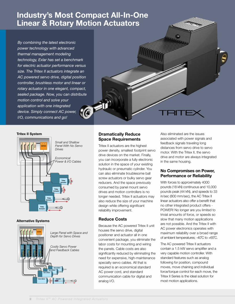
Industry’s Most Compact All-In-One Linear & Rotary Motion Actuators
PLC
TritexActuator
TritexActuator
TritexActuator
TritexActuator
230VAC
PL
C
Serv
oD
rive
Serv
oD
rive
Serv
oD
rive
Serv
oD
rive
230VAC
Servo Motor Actuator
Servo Motor
Servo Motor
Servo Motor
Small and Shallow Panel With No Servo Drives
Economical Power & I/O Cables
Large Panel with Space and Depth for Servo Drives
Costly Servo Power and Feedback Cables
Tritex II System
Alternative Systems
By combining the latest electronic
power technology with advanced
thermal management modeling
technology, Exlar has set a benchmark
for electric actuator performance versus
size. The Tritex II actuators integrate an
AC powered servo drive, digital position
controller, brushless motor and linear or
rotary actuator in one elegant, compact,
sealed package. Now, you can distribute
motion control and solve your
application with one integrated
device. Simply connect AC power,
I/O, communications and go!
Dramatically Reduce Space Requirements
Tritex II actuators are the highest power density, smallest footprint servo drive devices on the market. Finally, you can incorporate a fully electronic solution in the space of your existing hydraulic or pneumatic cylinder. You can also eliminate troublesome ball screw actuators or bulky servo gear reducers. And the space previously consumed by panel mount servo drives and motion controllers is no longer needed. Tritex II actuators may also reduce the size of your machine design while offering significant reliability improvement.
Reduce Costs
Because the AC powered Tritex II unit houses the servo drive, digital positioner and actuator all in one convenient package, you eliminate the labor costs for mounting and wiring the panels. Cable costs are also significantly reduced by eliminating the need for expensive, high-maintenance specialty servo cables. All that is required is an economical standard AC power cord, and standard communication cable for digital and analog I/O.
Also eliminated are the issues associated with power signals and feedback signals traveling long distances from servo drive to servo motor. With the Tritex II, the servo drive and motor are always integrated in the same housing.
No Compromises on Power, Performance or Reliability
With forces to approximately 4000 pounds (18 kN) continuous and 10,000 pounds peak (44 kN), and speeds to 33 in/sec (800 mm/sec), the AC Tritex II linear actuators also offer a benefit that no other integrated product offers - POWER! No longer are you limited to trivial amounts of force, or speeds so slow that many motion applications are not possible. And the Tritex II with AC power electronics operates with maximum reliability over a broad range of ambient temperatures; -40˚C to +65˚C.
The AC powered Tritex II actuators contain a 1.5 kW servo amplifier and a very capable motion controller. With standard features such as analog following for position, compound moves, move chaining and individual force/torque control for each move, the Tritex II Series is the ideal solution for most motion applications.
2 Tr i tex I I ™ AC Powered In tegra ted Actua to rs

Tr i tex I I ™ AC Powered In tegra ted Actua to rs 3
Flexible Communications
Multiple feedback types, including absolute feedback, allow you to select the system that is best-suited for your application. Digital and analog I/O plus popular communication networks such as Modbus TCP, Ethernet/IP and ProfiNet (future networks include CANopen and Hart) allow the Tritex II to become an integral part of your control architecture or machine control processes.
Linear Applications
Tritex II linear actuators employ Exlar’s patented, inverted roller screw mechanism for converting rotary motion to highly robust and long-life linear motion. These characteristics enable the Tritex actuator to solve applications that previously required pneumatic or hydraulic cylinders. No additional mechanisms (such as acme or ball screws) are necessary to convert the actuator’s rotary power into linear motion in order to move the load. Simple to configure, yet powerful interface software allows the Tritex II to perform nearly any motion requirements. Moves can be made to incremental or absolute positions, and also to preset forces or to a switch (input). Moves can be initiated by inputs, by other moves, or by events such as reaching a selected force. The Tritex II linear actuator can be programmed to follow an analog command signal, making it ideal for controlling valves and dampers in process control applications.
Rotary Applications
Tritex II rotary motors and gearmotors provide high response and precise control of a rotatable shaft similar to that found in any electric motor. The difference is that with Tritex II you can program (via your PC) the rotational speed and position of the output shaft in response to external commands. For example, the motor can be commanded to rotate at a controlled velocity and precisely stop at a preprogrammed position. You can also program the unit to run at a preset velocity until a switch input is received or a preprogrammed torque level is produced against a load. Alternatively, the rotary Tritex II actuators can be set up to follow an analog signal, either voltage or current, representing your choice of torque, velocity or position. Signals for initiating the preprogrammed velocity and position commands come from optically isolated inputs or via network communications. Likewise, isolated output commands of the status and events allow precise coordination with your system controls or machine operator.
Optional Internal Gear Reducer
If the application requires greater torque and less speed than available with the base unit, the Tritex II is available with an integral servo grade planetary gear reducer. Gear ratios of 4:1 to 100:1 allow the power of Tritex II to be applied over a broad range of torque requirements.
Applications
Roller Screw Basics
Exlar’s patented, inverted roller screw is a mechanism for converting rotary torque into linear motion, in a similar manner to acme screws or ball screws. But, unlike those devices, roller screws can carry heavy loads for thousands of hours in the most arduous conditions. This makes roller screws the ideal choice for demanding, continuous-duty linear motion applications. The difference is in the roller screw’s design for transmitting forces. Multiple threaded helical rollers are assembled in a planetary arrangement around a threaded shaft as seen below, which converts a motor’s rotary motion into linear movement of the shaft or nut.
Compare a similar size ball screw to Exlar’s planetary roller screw design and see many more contact points on the roller screw. This results in higher load-carrying capacity and improved stiffness.

4 Tr i tex I I ™ AC Powered In tegra ted Actua to rs
Typical Applications
• Process Control• Test• Simulation• Food Processing• Industrial
Automation• Forestry • Semi-conductor
• Remote Vehicles• Medical Equipment• Automotive
Assembly• Molding• Die Casting• Welding
The Exlar Advantage
Tritex II Models
• T2M standard mechanical capacity actuator, 90 and 115 mm
• T2X high mechanical capacity actuator, 90 and 115 mm
• R2M rotary motor, 90 and 115 mm• R2G rotary gearmotor, 90 and
115 mm
Power Requirements
• AC Power 100V - 240V, +/- 10%, single phase
• Built-in AC line filter• Connections for external
braking resistor
Feedback Types
• Analog Hall with 1000 count resolution
• Incremental encoder with 8192 count resolution
• Absolute Feedback (analog hall with multi-turn, battery backup)
Communications & I/O
Digital I/O:
• 8 digital inputs - 10 to 30 VDC opto-isolated• 4 digital outputs - 30 VDC maximum, 100 mA,
opto-isolated
Analog I/O:
• 1 analog input - 0-10V or +10V/-10V, 12 bit
resolution - Force/torque, velocity, position• 1 analog output - 0-10V mode - Force/torque, velocity, position• Optional isolated 4-20mA board - 1 4-20 mA isolated analog input,
16 bit resolution - 1 4-20 mA isolated analog output,
12 bit resolution
Standard Communications:
• 1 RS 485 port, Modbus RTU, opto-isolated for programming, controlling and monitoring
4 Tr i tex I I ™ AC Powered In tegra ted Actua to rs
Exlar has delivered thousands of roller
screw linear actuator solutions around
the world in applications ranging from
demanding automatic welding to
controlling fuel or steam valves on
turbine generators. Exlar’s linear
actuators provide trouble-free, precise
linear motion control for millions of
cycles of operation.
Tritex II rotary motor with cable glands shown left and Tritex II linear actuator with threaded ports shown below.
Class I Division 2 Rating
Exlar’s Tritex II actuators are available for applications requiring CSA Class I Division 2 certification. Ordering a standard I/O interconnect with or without 4-20 mA Analog I/O, and the N option for the NPT port will provide you with Class I Division 2 rated product.
Tritex II 230 V AC Agency ApprovalsAgency/Standard Tritex Models/Options
CE, EMC EN61800-3, Safety EN 61800-5-1 All models
CSA 139 All models
CSA Class I, Div 2 Requires NPT Connection Option. EIP, TCP and ABZ options are not covered
UL 508 C, Type 4 Enclosure
Requires NPT Connection Option. EIP, TCP and ABZ options are not covered
IP 65 Standard on T2X, R2M, R2G models, available on T2M models with P5 option
Vibration Rating
Standard: IEC 61800-5-1 safety standard for drives. 1g peak, up to 150 Hz for <2 hrs.Optional: (HV option) IEC 60068-2-64 random vibration standard, 2.5g rms, 50 to 500 Hz.
Backpanel LED Display
163694
Class I Div 2
POWER STATUS LED 1 LED 2

Tr i tex I I ™ AC Powered In tegra ted Actua to rs 5
Tritex II Series Operation
The Tritex II Series actuators can operate in one of five different motion-producing modes. These modes solve an endless variety of applications in industrial automation, medical equipment, fastening and joining, blow molding, injection molding, testing, food processing, and more.
Programmed functions are stored in the Tritex II non-volatile memory. A standard RS/485 serial interface allows control, programming and monitoring of all aspects of the motor or actuator as it performs your application. Optional communications protocols are available.
Operating Modes
1) Move to a position (or switch) The Tritex II Series actuators allow you to execute up to 16 programmed positions or distances. You may also use a limit switch or other input device as the end condition of a move. This combination of index flexibility provides a simple solution for point-to-point indexing.
2) Move to a preset force or torque The Tritex II Series allows you to terminate your move upon the achievement of a programmed torque or force. This is an ideal mode for pressing and clamping applications.
3) Position proportional to an analog signal
Ideal for process control solutions, the Tritex II Series provides the functionality to position a control valve by following an analog input signal. This allows the Tritex II Series to deliver precise valve control — control that cannot be achieved by other electric, hydraulic or pneumatic actuators.
4) Velocity proportional to an analog signal
Tritex II actuators offer you the capability to control velocity with an analog signal. This is particularly useful with Tritex II rotary motors offering precise control of the speed of any process or operation.
5) Force/torque proportional to analog signal
Perfect for pressing and torquing applications, you can control torque from an analog input while in torque mode.
Tritex Option Boards
• Option boards offer additional functionality to the base Tritex II actuators
- Terminal board for customer I/O - Terminal board for customer I/O plus
encoder output (requires encoder feedback (IE option))
- Isolated 4-20mA analog input and output
- Customer specific• Communication buses - EtherNet/IP - Modbus TCP - CANopen - PROFINET I/O - HART
Connectivity
• Internal terminals accessible through removable cover
• Threaded ports for cable glands• Optional connectors - M23 Power - M16 I/O • M8 connector for RS485• M12 connector for Ethernet options• Custom connection options
Tr i tex I I ™ AC Powered In tegra ted Actua to rs 5
Manual Override Options Handwheel This option gives you a manual engagement switch that can be used to disable the power to the actuator for manual operation without any external tools.
Side Drive This option allows for emergency operation in a power down condition using a standard socket wrench.
Selectable Input Functions• Enable
• Move (0-15)
• Dedicated Position
• Jog+
• Jog- select move (0-15)
• Jog Fast
• Home
• Extend Switch
• Retract Switch
• Home Switch
• Teach Enable
• Teach Move (0-15)
• Stop
• Hold
• Alternate Mode; allows you to switch between 2 operating modes.
Selectable Output Functions• Enabled
• Homed
• Ready (Enabled and Homed)
• Fault
• Warning
• Fault or Warning Active
• Move (0-15) in Progress
• Homing
• Jogging
• Jogging+
• Jogging-
• Motion
• In Position
• At Home Position
• At Move (0-15)
• Position
• Stopped
• Holding
• In Current Limit
• In Current Fold back
• Above Rated Current
• Home
6 Tr i tex I I ™ AC Powered In tegra ted Actua to rs
Expert, the Tritex II user interface software,
provides you with a simple way to select all
aspects of configuration and control required
to set up and operate a Tritex II actuator.
Easy-to-use tabbed pages provide access to
input all of the parameters necessary to
successfully configure your motion application.
‘Application’ files give you a convenient way to
store and redistribute configurations amongst
multiple computers, and ‘Drive’ files allow the
same configuration to be distributed to multiple
Tritex II actuators. Motion setup, homing,
teach mode, tuning parameters, jogging, I/O
configuration, and local control are all
accomplished with ease using Expert software.
Expert User Interface
6 Tr i tex I I ™ AC Powered In tegra ted Actua to rs
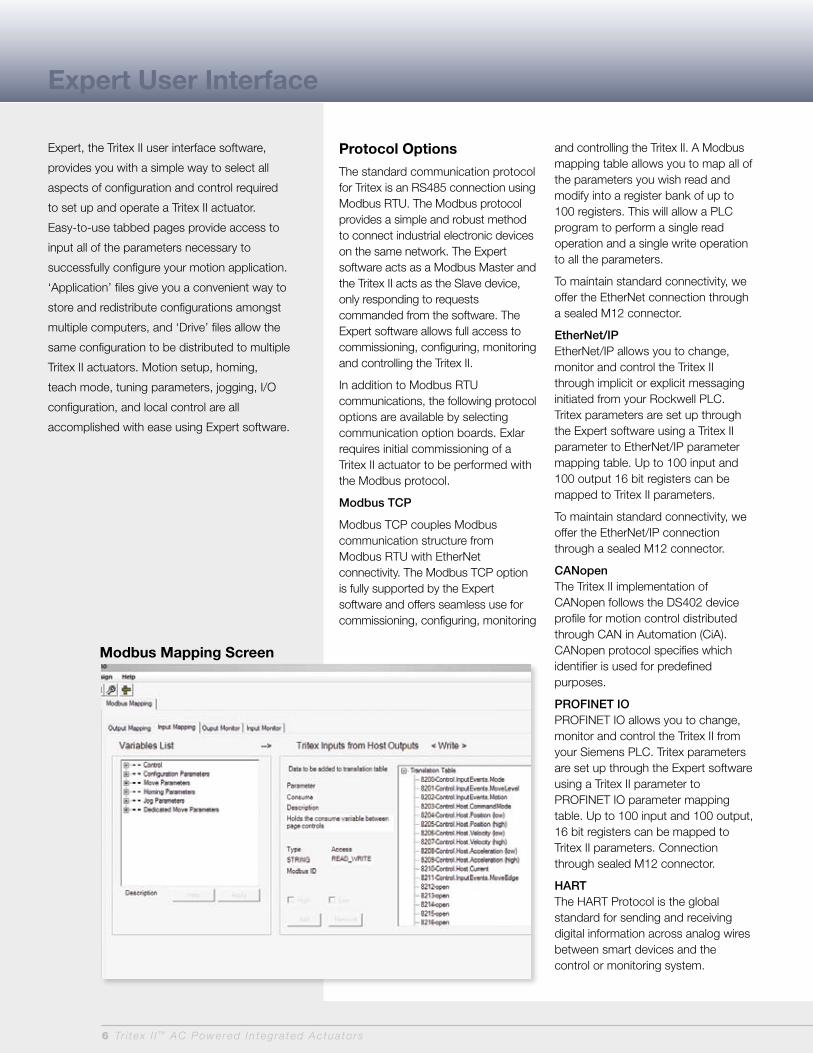
Protocol Options
The standard communication protocol for Tritex is an RS485 connection using Modbus RTU. The Modbus protocol provides a simple and robust method to connect industrial electronic devices on the same network. The Expert software acts as a Modbus Master and the Tritex II acts as the Slave device, only responding to requests commanded from the software. The Expert software allows full access to commissioning, configuring, monitoring and controlling the Tritex II.
In addition to Modbus RTU communications, the following protocol options are available by selecting communication option boards. Exlar requires initial commissioning of a Tritex II actuator to be performed with the Modbus protocol.
Modbus TCP
Modbus TCP couples Modbus communication structure from Modbus RTU with EtherNet connectivity. The Modbus TCP option is fully supported by the Expert software and offers seamless use for commissioning, configuring, monitoring
and controlling the Tritex II. A Modbus mapping table allows you to map all of the parameters you wish read and modify into a register bank of up to 100 registers. This will allow a PLC program to perform a single read operation and a single write operation to all the parameters.
To maintain standard connectivity, we offer the EtherNet connection through a sealed M12 connector.
EtherNet/IPEtherNet/IP allows you to change, monitor and control the Tritex II through implicit or explicit messaging initiated from your Rockwell PLC. Tritex parameters are set up through the Expert software using a Tritex II parameter to EtherNet/IP parameter mapping table. Up to 100 input and 100 output 16 bit registers can be mapped to Tritex II parameters.
To maintain standard connectivity, we offer the EtherNet/IP connection through a sealed M12 connector.
CANopenThe Tritex II implementation of CANopen follows the DS402 device profile for motion control distributed through CAN in Automation (CiA). CANopen protocol specifies which identifier is used for predefined purposes.
PrOFINET IOPROFINET IO allows you to change, monitor and control the Tritex II from your Siemens PLC. Tritex parameters are set up through the Expert software using a Tritex II parameter to PROFINET IO parameter mapping table. Up to 100 input and 100 output, 16 bit registers can be mapped to Tritex II parameters. Connection through sealed M12 connector.
HArTThe HART Protocol is the global standard for sending and receiving digital information across analog wires between smart devices and the control or monitoring system.
Modbus Mapping Screen
Tr i tex I I ™ AC Powered In tegra ted Actua to rs 7Tr i tex I I ™ AC Powered In tegra ted Actua to rs 7
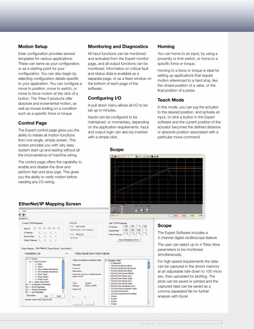
EtherNet/IP Mapping Screen
Motion Setup
Exlar configuration provides several templates for various applications. These can serve as your configuration, or as a starting point for your configuration. You can also begin by selecting configuration details specific to your application. You can configure a move to position, move to switch, or move to force motion at the click of a button. The Tritex II products offer absolute and incremental motion, as well as moves ending on a condition such as a specific force or torque.
Control Page
The Expert control page gives you the ability to initiate all motion functions from one single, simple screen. This screen provides you with very easy system start-up and testing without all the inconvenience of machine wiring.
The control page offers the capability to enable and disable the drive and perform fast and slow jogs. This gives you the ability to verify motion before needing any I/O wiring.
Monitoring and Diagnostics
All input functions can be monitored and activated from the Expert monitor page, and all output functions can be monitored. Information on critical fault and status data is available as a separate page, or as a fixed window on the bottom of each page of the software.
Configuring I/O
A pull down menu allows all I/O to be set up in minutes.
Inputs can be configured to be maintained, or momentary, depending on the application requirements. Input and output logic can also be inverted with a simple click.
Homing
You can home to an input, by using a proximity or limit switch, or home to a specific force or torque.
Homing to a force or torque is ideal for setting up applications that require motion referenced to a hard stop, like the closed position of a valve, or the final position of a press.
Teach Mode
In this mode, you can jog the actuator to the desired position, and activate an input, or click a button in the Expert software and the current position of the actuator becomes the defined distance or absolute position associated with a particular move command.
Scope
Scope
The Expert Software includes a 4 channel digital oscilloscope feature.
The user can select up to 4 Tritex drive parameters to be monitored simultaneously.
For high speed requirements the data can be captured in the drive’s memory at an adjustable rate down to 100 micro sec, then uploaded for plotting. The plots can be saved or printed and the captured data can be saved as a comma separated file for further analysis with Excel.

8 Tr i tex I I ™ AC Powered In tegra ted Actua to rs
Process Control Functionality
Tritex II actuators, available in both rotary and
linear versions, provide a perfect solution for
your valve actuation needs. Small hysteresis
and dead band, quick response to small signal
changes and stable dynamic responses
delivered by Tritex II actuators are all key
parameters for process control.
Fully programmable to follow an analog signal
representing either position or force, the Tritex
II linear actuator is perfectly designed for
sliding stem valve applications with thrust
requirements up to 3685 lbs. Highly accurate
position feedback allows the Tritex II to achieve
combined repeatability and hysteresis as low
as 0.25%.
The Tritex II Rotary actuators are ideal for
operating quarter-turn, full-turn, or multi-turn
valves or shaft driven dampers. In shaft driven
applications, the rotary Tritex II actuators are
directly coupled shaft-to-shaft. This eliminates
the ungainly mechanisms usually necessary to
convert the linear motion of pneumatic and
hydraulic cylinders to rotational motion. Gear
ratios of 4:1 to 100:1 allow the power of Tritex II
to be applied to a broad range of applications.
Tritex II actuators can be mounted on any valve
from any manufacturer.
Valve Software
Our valve software is simple to use, featuring a
teach mode for foolproof configuration.
Included is a programmable valve cut off
position feature that enables a firm valve
seat on both new valves, or retrofitted valves.
Class I Division 2 Rating
Exlar’s Tritex II actuators are available for
applications requiring CSA Class I Division 2
certification. Ordering a standard I/O
interconnect with or without 4-20 mA Analog
I/O, and the N option for the NPT port will
provide you with Class I Division 2 rated product.
Benefits for Process Control Applications
100% Torque AvailabilityFull Torque means almost zero deadband, and stiction in the valve stem is no problem. Current is always available so it will hold its position. This provides excellent process loop control.
Speed of responseTritex II response rate is measured in milliseconds. This provides excellent modulating control of both ball valves and butterfly valves.
High AccuracyTritex II actuators have a built-in position feedback sensor, providing much higher accuracy over potentiometer-based actuators.
Custom Valve SeatExlar linear actuators stroke the valve based on position, but can switch to torque mode when seating the valve. This allows a tight cut-off. It also helps with retrofitting valves that may have some wear. For new valves, it makes sure damage isn’t done due to over-forcing the stroke.
High StiffnessSimilar to hydraulic actuators, but without the cost or maintenance issues, Tritex II actuators are extremely stiff. This allows control down to the smallest operating range (<1%) and also eliminates dynamic flow problems such as negative gradients.
Fast Stroke SpeedsMost other electric actuators are known for being slow - a major disadvantage. Tritex actuators can close a valve in milliseconds if needed.
Improved ControlUnder modulating conditions, Tritex II actuators provide precise closed loop tracking by effectively eliminating non-linearities and deadtime.
Absolute FeedbackThe absolute feedback option gives the actuator memory after teaching the valve limits. Upon power loss, the battery backup will maintain the valve limits.
Class I, Div 2163694 8

Tr i tex I I ™ AC Powered In tegra ted Actua to rs 9
Travel LifeT2M/T2X Lifetime CurvesThe L10 expected life of a roller screw linear actuator is expressed as the linear travel distance that 90% of properly maintained roller screws manufactured are expected to meet or exceed. For higher than 90% reliability, the result should be multiplied by the following factors: 95% x 0.62; 96% x 0.53; 97% x 0.44; 98% x 0.33; 99% x 0.21. This is not a guarantee and these charts should be used for estimation purposes only.
The underlying formula that defines this value is:
Travel life in millions of inches, where:
C = Dynamic load rating (lbf)
F = Cubic mean applied load (lbf)
S = Roller screws lead (inches)
Extended TemperatureDe-Rating CurveThe speed/torque curves are based on 25˚ C ambient conditions. The actuators may be operated at ambient temperatures up to 65˚ C. Use the curve shown right for continuous torque/force deratings above 25˚ C.
T2X115-xx01T2X115-xx02T2X115-xx05T2X115-xx08x
xx x
x x
x
xx
x
x
4,000
3,500
3,000
2,500
2,000
1,500
1,000
500
0
1 10 100 1,000 10,000 100,000
Cu
bic
Me
an
Lo
ad
(lb
f)
Travel Life (Millions of inches)
T2X115L10 Travel Life
T2M090T2M115
1800
1600
1400
1200
1000
800
600
400
200
0
Cu
bic
Me
an
Lo
ad
(lb
f)
T2M090 and T2M115 L10 Travel Life
10 100 1,000 10,000 100,000Travel Life (Millions of inches)
2,000
1,800
1,600
1,400
1,200
1,000
800
600
400
200
010 100 1,000 10,000 100,000
Cu
bic
Me
an
Lo
ad
(lb
f)
Travel Life (Millions of inches)
T2X090L10 Travel Life
All curves represent properly lubricated and maintained actuators.
% Stall Torque 120
100
80
60
40
20
0 -20 -15 -10 -5 0 5 10 15 20 25 30 35 40 45 50 55 60 65
Temp, Deg C
% of Available Stall Torque vs Ambient Temperature
115mm90mm
T2X090L10 Travel Life
T2X115L10 Travel Life
T2M090 and T2M115L10 Travel Life
L10 = ( C )3 x S = F
Travel Life and Temperature Ratings

10 Tr i tex I I ™ AC Powered In tegra ted Actua to rs
0
T2M/X090 with 238-40 Stator*
Forc
e lb
f (N
)
1.67 3.33 5.00 6.67 (42.4) (84.6) (127.0) (169.4) 3.33 6.67 10.00 13.33 (84.6) (169.4) (254.0) (338.6) 8.33 16.67 25.00 33.33 (211.6) (423.4) (635.0) (846.6)
700 1,750 3,500 (3,110) (7,780) (15,570)
600 1,500 3,000 (2,700) (6,670) (13.340)
500 1,250 2,500 (2,220) (5,560) (11,100)
400 1,000 2,000 (1,780) (4,450) (8,900)
300 750 1,500 (1,330) (3,330) (6,670)
200 500 1,000 (890) (2,220) (4,450)
100 250 500 (440) (1,110) (2,220)
0
120 VAC 208 VAC
Peak
Continuous
LEAD inch (mm)
0.1 (2.54)
0.2 (5.08)
0.5 (12.70)
Speed inch/sec (mm/sec)
LEAD inch (mm) 0.5 0.2 0.1 (12.70) (5.08) (2.54)
0 1.67 3.33 5.00 6.67 8.33 10.00 (42.4) (84.6) (127.0) (169.4) (211.6) (254.0) 4.16 8.33 12.50 16.67 20.83 25.00 (105.7) (211.6) (317.5) (423.4) (529.1) (635.0)
900 2,250 (4,000) (10,000) 800 2,000 (3,560) (8,900) 700 1,750 (3,110) (7,780) 600 1,500 (2,700) (6,670) 500 1,250 (2,220) (5,560) 400 1,000 (1,780) (4,450) 300 750 (1,330) (3,330) 200 500 (890) (2,220) 200 250 (440) (1,110) 0
120 VAC 208 VAC
T2M/X090 with 238-30 Stator*
Forc
e lb
f (N
)
Peak
Continuous
LEAD inch (mm)
0.2 (5.08)
0.5 (12.70)
Speed inch/sec (mm/sec)
LEAD inch (mm) 0.5 0.2
(12.70) (5.08)
0
Speed inch/sec (mm/sec)
T2M/X090 with 138-40 Stator* Peak
ContinuousFo
rce
lbf
(N)
LEAD inch (mm) 0.5 0.2 0.1 (12.70) (5.08) (2.54)
1.67 3.33 5.00 6.67 (42.2) (84.6) (127) (169.4) 3.33 6.67 10.00 13.33 (84.6) (169.4) (254.0) (338.6) 8.33 16.67 25.00 33.33 (211.6) (423.4) (635.0) (846.6)
LEAD inch (mm)
0.1 (2.54)
0.2 (5.08)
0.5 (12.70)
600 1,500 3,000 (2,700) (6,670) (13.340)
500 1,250 2,500 (2,220) (5,560) (11,100)
400 1,000 2,000 (1,780) (4,450) (8,900)
300 750 1,500 (1,330) (3,330) (6,670)
200 500 1,000 (890) (2,220) (4,450)
100 250 500 (440) (1,110) (2,220)
0
120 VAC 208 VAC
T2M/X090 Linear Actuator Speed vs. Force Curves
*Test data derived using NEMA recommended aluminum heatsink 10" x 10" x 3/8".

0
Forc
e lb
f (N
)
LEAD inch (mm) 0.75 0.5 0.2 (19.05) (12.70) (5.08)
1.67 3.33 5.00 (42.4) (84.6) (127.0) 4.16 8.33 12.50 (105.7) (211.6) (317.5) 6.25 12.50 18.75 (159.0) (317.5) (476.3)
1,300 2,000 5,000 (5,800) (8,900) (22,200)
1,000 1,500 3,750 (4,450) (6,670) (16,700)
650 1,000 2,500 (2,900) (4,450) (11,100)
325 500 1,250 (1,450) (2,220) (5,560)
0
120 VAC 208 VAC
T2M/X115 with 238-15 Stator*Peak
Continuous
LEAD inch (mm)
0.2 (5.08)
0.5 (12.70)
0.75 (19.05)
Speed inch/sec (mm/sec)
Tr i tex I I ™ AC Powered In tegra ted Actua to rs 11
T2M/X115 Linear Actuator Speed vs. Force Curves
0
T2M/X115 with 138-30 Stator*
Forc
e lb
f (N
)
LEAD inch (mm) 0.75 0.5 0.2 0.1 (19.05) (12.70) (5.08) (2.54)
.83 1.67 2.50 3.33 4.17 5.00 (21.1) (42.4) (63.5) (84.6) (105.9) (127.0) 1.67 3.33 5.00 6.67 8.33 10.00 (42.4) (84.6) (127.0) (169.4) (211.6) (254.0) 4.16 8.33 12.50 16.67 20.83 25.00 (105.7) (211.6) (317.5) (423.4) (529.1) (635.0) 6.25 12.50 18.75 25.00 31.25 37.50 (159.0) (317.5) (476.3) (635.0) (794.0) (952.5)
650 1,000 2,500 5,000 (2,900) (4,450) (11,100) (22,240)
550 840 2,000 4,000 (2,450) (3,730) (8,900) (17,800)
400 600 1,500 3,000 (1,800) (2,670) (6,670) (13,300)
250 400 1,000 2,000 (1,110) (1,780) (4,450) (8,900)
125 200 500 1,000 (550) (890) (2,220) (4,450)
0
120 VAC 208 VAC
Peak
Continuous
LEAD inch (mm)
0.1 (2.54)
0.2 (5.08)
0.5 (12.70)
0.75 (19.05)
Speed inch/sec (mm/sec)
0
Forc
e lb
f (N
)
.83 1.67 2.50 3.33 (21.1) (42.4) (63.5) (84.6) 1.67 3.33 5.00 6.67 (42.4) (84.6) (127.0) (169.4) 4.16 8.33 12.50 16.67 (105.7) (211.6) (317.5) (423.40 6.25 12.50 18.75 25.00 (159.0) (317.5) (476.3) (635.0)
1,100 1,600 4,000 8,000 (4,900) (7,100) (17,800) (35,600) 900 1,400 3.500 7,000 (4,000) (6,200) (15,600) (31,100) 800 1,200 3,000 6,000 (3,500) (5,300) (13,300) (26,700) 650 1,000 2,500 5,000 (2,900) (4,450) (11,100) (22,240) 550 840 2,000 4,000 (2,450) (3,730) (8,900) (17,800) 400 600 1,500 3,000 (1,800) (2,670) (6,670) (13,300) 250 400 1,000 2,000 (1,110) (1,780) (4,450) (8,900) 125 200 500 1,000 (550) (890) (2,220) (4,450) 0
T2M/X115 with 238-20 Stator* LEAD inch (mm) 0.75 0.5 0.2 0.1 (19.05) (12.70) (5.08) (2.54)
Peak
Continuous
LEAD inch (mm)
0.1 (2.54)
0.2 (5.08)
0.5 (12.70)
0.75 (19.05)
Speed inch/sec (mm/sec)
120 VAC 208 VAC
*Test data derived using NEMA recommended aluminum heatsink 12" x 12" x 1/2".

12 Tr i tex I I ™ AC Powered In tegra ted Actua to rs
R2M Rotary Motor Speed vs. Torque Curves
R2M090 R2M115
0 500 1,000 1,500 2,000 2,500 3,000
RPM
90.0 (10.1) 80.0 (9.0) 70.0 (7.9) 60.0 (6.8) 50.0 (5.6) 40.0 (4.5) 30.0 (3.4) 20.0 (2.3) 10.0 (1.1) 0
TorqueLbf-in (Nm)
R2M090 with 238-30 Stator* Peak
Continuous
120 VAC 208 VAC
0 500 1,000 1,500 2,000RPM
120.0 (13.6)
100.0 (11.3)
80.0 (9.0)
60.0 (6.8)
40.0 (4.5)
20.0 (2.3)
0
TorqueLbf-in (Nm)
R2M090 with 338-20 Stator* Peak
Continuous
120 VAC 208 VAC
For R2G gearmotors, multiply torque by gear ratio and efficiency. Divide speed by gear ratio.
0 500 1,000 1,500 2,000 2,500 3,000 3,500 4,000
RPM
70.0
(7.9)
60.0 (6.8)
50.0 (5.6)
40.0 (4.5)
30.0 (3.4)
20.0 (2.3)
10.0 (1.1)
0
TorqueLbf-in (Nm)
R2M090 with 238-40 Stator* Peak
Continuous
120 VAC 208 VAC
0 500 1,000 1,500 2,000 2,500 3,000
RPM
100.0 (11.3)
80.0 (9.0)
60.0 (6.8)
40.0 (4.5)
20.0 (2.3)
0
TorqueLbf-in (Nm)
R2M115 with 138-30 Stator* Peak
Continuous
120 VAC 208 VAC
0 500 1,000 1,500 RPM
200.0 (22.6)
150.0 (16.9)
100.0 (11.3)
50.0 (5.6)
0
TorqueLbf-in (Nm)
R2M115 with 238-15 Stator* Peak
Continuous
120 VAC 208 VAC
0 500 1,000 1,500 2,000
RPM
160.0 (18.1)
140.0 (15.8)
120.0 (13.6)
100.0 (11.3)
80.0 (9.0)
60.0 (6.8)
40.0 (4.5)
20.0 (2.3)
0
TorqueLbf-in (Nm)
R2M115 with 238-20 Stator* Peak
Continuous
120 VAC 208 VAC
* R2M090 test data derived using NEMA recommended aluminum heatsink 10" x 10" x 3/8".
* R2M115 test data derived using NEMA recommended aluminum heatsink 12" x 12" x 1/2".

Tr i tex I I ™ AC Powered In tegra ted Actua to rs 13
T2M/X Linear Actuator Performance Specifications
T2M/X115 Linear Actuator Performance SpecificationsBacklash in (mm) .008 (.20)
Lead Accuracy in/ft (mm/300 mm) .001 (.025)
Maximum Radial Load lb (N) 15 (67)
Environmental Rating: Std IP54 / IP65
Stator 1 Stack 138-30 2 Stack 238-20 2 Stack 238-15
Lead RPM @ 240 VAC 3000 2000 1500
0.1
Continuous Stall Force lbf (N) 2354 (10470) 3685 (16391) NA
Peak Stall Force lbf (N) 4709 (20947) 7370 (32783) NA
Max Speed in/sec (mm/sec) 5.00 (127) 3.33 (84) NA
0.2
Continuous Stall Force lbf (N) 1177 (5235) 1843 (8198) 2380 (10586)
Peak Stall Force lbf (N) 2354 (10471) 3685 (16392) 4760 (21174)
Max Speed in/sec (mm/sec) 10.00 (254) 6.67 (169) 5.00 (127)
0.5
Continuous Stall Force lbf (N) 471 (2095) 737 (3278) 952 (4234)
Peak Stall Force lbf (N) 942 (4190) 1474 (6557) 1904 (8469)
Max Speed in/sec (mm/sec) 25.00 (635) 16.67 (423) 12.50 (317)
0.75
Continuous Stall Force lbf (N) 314 (1397) 491 (2184) 635 (2825)
Peak Stall Force lbf (N) 628 (2793) 982 (4368) 1370 (6094)
Max Speed in/sec (mm/sec) 37.5 (953) 25 (635) 18.75 (476)
Drive Current @ Continuous Stall Force Amps 8.5 8.5 8.5
Available Stroke Lengths in (mm) 6 (150), 10 (254), 12 (300), 18 (450)
Approximate Weight lb (kg) 34 (15.5)6 inch stroke, 1 stack
2 (1)Added weight per in of stroke
8 (4)Added weight per motor stack
4 (2)Added weight for brake
Continuous AC Input Current* Amps 8.3 8.3 8.3
Continuous input current rating is defined by UL and CSA.Ratings based on 25˚C conditions.
T2M/X090 Linear Actuator Performance SpecificationsBacklash in (mm) .008 (.20)
Lead Accuracy in/ft (mm/300 mm) .001 (.025)
Maximum Radial Load lb (N) 15 (67)
Environmental Rating: Std IP54 / IP65
Stator 1 Stack 138-40 2 Stack 238-40 2 Stack 238-30
Lead RPM @ 240 VAC 4000 4000 3000
0.1
Continuous Stall Force lbf (N) 1205 (5360) 1587 (7059) NA
Peak Stall Force lbf (N) 2411 (10725) 3175 (14123) NA
Max Speed in/sec (mm/sec) 6.67 (169) 6.67 (169) NA
0.2
Continuous Stall Force lbf (N) 603 (2682) 794 (3532) 1047 (4657)
Peak Stall Force lbf (N) 1205 (5360) 1587 (7059) 2094 (9315)
Max Speed in/sec (mm/sec) 13.33 (338) 13.33 (338) 10.00 (254)
0.5
Continuous Stall Force lbf (N) 241 (1072) 317 (1410) 419 (1864)
Peak Stall Force lbf (N) 482 (2144) 635 (2825) 838 (3728)
Max Speed in/sec (mm/sec) 33.33 (846) 33.33 (846) 25.00 (635)
Drive Current @ Continuous Stall Force Amps 5.7 7.5 7.5
Available Stroke Lengths in (mm) 3 (75), 6 (150), 10 (254), 12 (300), 18 (450)
Approximate Weight lb (kg) 14 (6.35)3 inch stroke, 1 stack
1 (0.5)Added weight per in of stroke
3 (1.4)Added weight per motor stack
3 (1.4)Added weight for brake
Continuous AC Input Current* Amps 6.3 6.3 6.3
Continuous input current rating is defined by UL and CSA.Ratings based on 25˚C conditions.

14 Tr i tex I I ™ AC Powered In tegra ted Actua to rs
R2M090 Rotary Motor Torque and Speed RatingsStator 2 Stack 238-40 2 Stack 238-30 3 Stack 338-20
RPM at 240 VAC 4000 3000 2000
Continuous Stall Torque lbf-in (Nm) 30 (3.4) 40 (4.5) 52 (5.9)
Peak Torque lbf-in (Nm) 60 (6.8) 80 (9.0) 105 (11.9)
Drive Current @ Continuous Stall Torque Amps 7.5 7.5 6.6
Continuous AC Input Current* Amps 6.3 6.3 6.3
*Continuous input current rating is defined by UL and CSA. Ratings based on 25˚C ambient conditions. For output torque of R2G gearmotors, multiply by ratio and efficiency. Please note maximum allowable output torques found at bottom of page.
R2M/R2G090 Inertia Stator 2 Stack 3 Stack
R2M Motor Armature Inertia (+/-5%) lb-in-sec2 (kg-cm2) 0.00097 (1.09) 0.00140 (1.58)
R2G Gearmotor Armature Inertia* lbf-in-sec2 (kg-cm2) 0.00157 (1.77) 0.00200 (2.26)
*Add armature inertia to gearing inertia for total inertia.
Radial Load and Bearing LifeRPM 50 100 250 500 1000
lbf (N) 389 (1730)
309 (1375)
227 (1010)
180 (801)
143 (636)
Side load ratings shown above are for 10,000 hour bearing life at 25mm from motor face at given rpm.
R2G090 Gearmotor Mechanical Ratings
Maximum Allowable Output Torque-Set by User lbf-in (Nm)
Output Torque at Motor Speed for 10,000 Hour Life
Model Ratio 1000 RPM lbf-in (Nm) 1500 RPM lbf-in (Nm) 2000 RPM lbf-in (Nm)
R2G090-004 4:1 2078 (234.8) 600 (67.8) 552 (62.4) 504 (56.9)
R2G090-005 5:1 1798 (203.1) 775 (87.6) 714 (80.7) 652 (73.7)
R2G090-010 10:1 1126 (127.2) 890 (100.6) 820 (92.7) 750 (84.7)
R2G090-016 16:1 2078 (234.8) 912 (103.4) 830 (94.7) 763 (86.2)
R2G090-020 20:1 2078 (234.8) 980 (110.7) 900 (101.7) 820 (92.6)
R2G090-025 25:1 1798 (203.1) 1250 (141.2) 1150 (130) 1050 (118.6)
R2G090-040 40:1 2078 (234.8) 1200 (135.6) 1107 (125) 1013 (114.4)
R2G090-050 50:1 1798 (203.1) 1550 (169.4) 1434 (162) 1317 (148.8)
R2G090-100 100:1 1126 (127.2) 1100 (124.3) 1100 (124.3) 1100 (124.3)
Two torque ratings for the R2G gearmotors are given in the table above. The left hand columns give the maximum (peak) allowable output torque for the indicated ratios of each size R2G gearmotor. This is not the rated output torque of the motor multiplied by the ratio of the reducer.It is possible to select a configuration of the motor selection and gear ratio such that the rated motor torque, multiplied by the gear ratio exceeds these ratings. It is the responsibility of the user to ensure that the settings of the system do not allow these values to be exceeded.The right hand columns give the output torque at the indicated speed which will result in 10,000 hour life (L10). The setup of the system will determine the actual output torque and speed.
R2M/R2G090 Rotary Motor/Gearmotor Performance Specifications
R2G090 Gearing Reflected InertiaSingle Reduction Double Reduction
Gear Stages lbf-in-sec2 (kg-cm2) Gear Stages lbf-in-sec2 (kg-cm2)
4:1 0.000154 (0.174) 16:1 0.000115 (0.130)
5:1 0.000100 (0.113) 20:1, 25:1 0.0000756 (0.0854)
10:1 0.0000265 (0.0300) 40:1, 50:1, 100:1 0.0000203 (0.0230)
Backlash and EfficiencySingle
ReductionDouble
Reduction
Backlash at 1% Rated Torque 10 Arc min 13 Arc min
Efficiency 91% 86%
R2M090 Motor and RTG090 Gearmotor WeightsR2M090
without GearsR2G090 with
1 Stage GearingR2G090 with
2 Stage GearingAdded Weight
for Brake
1 Stack Stator lb (kg) 11 (4.9) 19 (8.6) 22 (10)
3 (1.4)2 Stack Stator lb (kg) 14 (6.4) 22 (10) 25 (11.3)
3 Stack Stator lb (kg) 17 (7.7) 25 (11.3) 28 (12.7)
Tr i tex I I ™ AC Powered In tegra ted Actua to rs 15
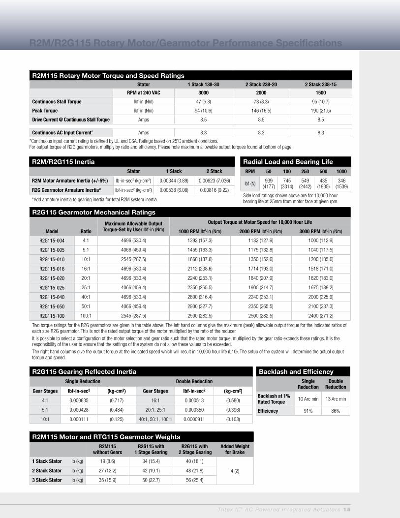
R2M/R2G115 Inertia Stator 1 Stack 2 Stack
R2M Motor Armature Inertia (+/-5%) lb-in-sec2 (kg-cm2) 0.00344 (3.89) 0.00623 (7.036)
R2G Gearmotor Armature Inertia* lbf-in-sec2 (kg-cm2) 0.00538 (6.08) 0.00816 (9.22)
*Add armature inertia to gearing inertia for total R2M system inertia.
Radial Load and Bearing LifeRPM 50 100 250 500 1000
lbf (N) 939 (4177)
745 (3314)
549 (2442)
435 (1935)
346 (1539)
Side load ratings shown above are for 10,000 hour bearing life at 25mm from motor face at given rpm.
R2G115 Gearing Reflected InertiaSingle Reduction Double Reduction
Gear Stages lbf-in-sec2 (kg-cm2) Gear Stages lbf-in-sec2 (kg-cm2)
4:1 0.000635 (0.717) 16:1 0.000513 (0.580)
5:1 0.000428 (0.484) 20:1, 25:1 0.000350 (0.396)
10:1 0.000111 (0.125) 40:1, 50:1, 100:1 0.0000911 (0.103)
Backlash and EfficiencySingle
ReductionDouble
Reduction
Backlash at 1% Rated Torque 10 Arc min 13 Arc min
Efficiency 91% 86%
R2M115 Motor and RTG115 Gearmotor WeightsR2M115
without GearsR2G115 with
1 Stage GearingR2G115 with
2 Stage GearingAdded Weight
for Brake
1 Stack Stator lb (kg) 19 (8.6) 34 (15.4) 40 (18.1)
4 (2)2 Stack Stator lb (kg) 27 (12.2) 42 (19.1) 48 (21.8)
3 Stack Stator lb (kg) 35 (15.9) 50 (22.7) 56 (25.4)
R2M/R2G115R2M115 Rotary Motor Torque and Speed RatingsStator 1 Stack 138-30 2 Stack 238-20 2 Stack 238-15
RPM at 240 VAC 3000 2000 1500
Continuous Stall Torque lbf-in (Nm) 47 (5.3) 73 (8.3) 95 (10.7)
Peak Torque lbf-in (Nm) 94 (10.6) 146 (16.5) 190 (21.5)
Drive Current @ Continuous Stall Torque Amps 8.5 8.5 8.5
Continuous AC Input Current* Amps 8.3 8.3 8.3
*Continuous input current rating is defined by UL and CSA. Ratings based on 25˚C ambient conditions. For output torque of R2G gearmotors, multiply by ratio and efficiency. Please note maximum allowable output torques found at bottom of page.
R2M/R2G115 Rotary Motor/Gearmotor Performance Specifications
R2G115 Gearmotor Mechanical Ratings
Maximum Allowable Output Torque-Set by User lbf-in (Nm)
Output Torque at Motor Speed for 10,000 Hour Life
Model Ratio 1000 RPM lbf-in (Nm) 2000 RPM lbf-in (Nm) 3000 RPM lbf-in (Nm)
R2G115-004 4:1 4696 (530.4) 1392 (157.3) 1132 (127.9) 1000 (112.9)
R2G115-005 5:1 4066 (459.4) 1455 (163.3) 1175 (132.8) 1040 (117.5)
R2G115-010 10:1 2545 (287.5) 1660 (187.6) 1350 (152.6) 1200 (135.6)
R2G115-016 16:1 4696 (530.4) 2112 (238.6) 1714 (193.0) 1518 (171.0)
R2G115-020 20:1 4696 (530.4) 2240 (253.1) 1840 (207.9) 1620 (183.0)
R2G115-025 25:1 4066 (459.4) 2350 (265.5) 1900 (214.7) 1675 (189.2)
R2G115-040 40:1 4696 (530.4) 2800 (316.4) 2240 (253.1) 2000 (225.9)
R2G115-050 50:1 4066 (459.4) 2900 (327.7) 2350 (265.5) 2100 (237.3)
R2G115-100 100:1 2545 (287.5) 2500 (282.5) 2500 (282.5) 2400 (271.2)
Two torque ratings for the R2G gearmotors are given in the table above. The left hand columns give the maximum (peak) allowable output torque for the indicated ratios of each size R2G gearmotor. This is not the rated output torque of the motor multiplied by the ratio of the reducer.It is possible to select a configuration of the motor selection and gear ratio such that the rated motor torque, multiplied by the gear ratio exceeds these ratings. It is the responsibility of the user to ensure that the settings of the system do not allow these values to be exceeded.The right hand columns give the output torque at the indicated speed which will result in 10,000 hour life (L10). The setup of the system will determine the actual output torque and speed.

16 Tr i tex I I ™ AC Powered In tegra ted Actua to rs
T2M/X090 Linear Actuator Dimensions
T2M/X090 Double Side Mount or Extended Tie Rod Mount
T2M/X090 Side Trunnion Mount or Rear Clevis Mount
T2M/X090 Front, Rear, or Front and Rear Flange Mount
DIM 3 inch (75 mm) stroke in (mm)
6 inch (150 mm) stroke in (mm)
10 inch (250 mm) stroke in (mm)
12 inch (300 mm) stroke in (mm)
18 inch (450 mm) stroke in (mm)
A 11.54 (293.1) 14.01 (355.9) 18.53 (470.7) 20.53 (521.5) 26.53 (673.9)
B 6.15 (156.1) 8.62 (218.9) 13.12 (333.3) 15.12 (434.8) 21.12 (536.4)
C 5.38 (136.7) 8.01 (203.4) 10.00 (254.0) 12.00 (304.8) 18.00 (457.2)
D 13.52 (343.3) 15.99 (406.1) 20.49 (520.4) 22.49 (571.2) 28.49 (723.6)
Note: Add 1.61 inches to dimensions “A” and “D” if ordering a brake.
* “N” option utilizes adapter from M20 x 1.5 to 1/2" NPT thread. Dia. 1-5/16 (24mm), length 3/4" (19mm).
* “N” option utilizes adapter from M20 x 1.5 to 1/2" NPT thread. Dia. 1-5/16 (24mm), length 3/4" (19mm).
* “N” option utilizes adapter from M20 x 1.5 to 1/2" NPT thread. Dia. 1-5/16 (24 mm), length 3/4" (19 mm).
in (mm)

Tr i tex I I ™ AC Powered In tegra ted Actua to rs 17
T2M/X115 Linear Actuator Dimensions
T2M/X115 Double Side Mount or Extended Tie Rod Mount
T2M/X115 Side Trunnion Mount or Rear Clevis Mount
T2M/X115 Front, Rear, or Front and Rear Flange Mount
DIM 6 inch (150 mm) stroke in (mm)
10 inch (250 mm) stroke in (mm)
12 inch (300 mm) stroke in (mm)
18 inch (450 mm) stroke in (mm)
A 15.79 (401.1) 19.79 (502.7) 21.79 (553.5) 27.79 (705.9)
B 10.31 (261.8) 14.31 (363.5) 16.31 (414.3) 22.31 (566.7)
C 6.00 (152.4) 10.00 (254.0) 12.00 (304.8) 18.00 (457.2)
D 17.99 (456.9) 21.99 (558.5) 23.99 (609.3) 29.99 (761.7)
Note: Add 2.33 inches to dimensions “A” and “D” if ordering a brake.
* “N” option utilizes adapter from M20 x 1.5 to 1/2" NPT thread. Dia. 1-5/16 (24mm), length 3/4" (19mm).
* “N” option utilizes adapter from M20 x 1.5 to 1/2" NPT thread. Dia. 1-5/16 (24mm), length 3/4" (19mm).
* “N” option utilizes adapter from M20 x 1.5 to 1/2" NPT thread. Dia. 1-5/16 (24 mm), length 3/4" (19 mm).

18 Tr i tex I I ™ AC Powered In tegra ted Actua to rs
3.5490
3.94 BC100
4X .28 on BC7
3.14923.1485
[80mm(g6)]
3.5490
.8521.5
.2360
.2348[6mm(h9)]
2.1555
1.5740 Dim "A"
.123
.7480
.7475[19mm(h6)]
6.95177
.3910
1.3835
RS485
3.5490
3.14923.1485
[80mm(g6)]
.9624.5
.2362
.2350[6mm(h9)]
3.937 BC100
4X .257 on BC6.5
Dim "A"1.8948
.1183
.8665
.8660[22mm(g6)]
1.41736
.1203
2.1555
6.95177
.6316
RS485
1.2532
3.7495
* Power and I/O"G" = (2x) M20x1.5
R2M/R2G090 Rotary Motor/Gearmotor Dimensions
R2M090 Dimensions
R2G090 Dimensions
* “N” option utilizes adapter from M20 x 1.5 to 1/2" NPT thread. Dia. 1-5/16 (24mm), length 3/4" (19mm).
* “N” option utilizes adapter from M20 x 1.5 to 1/2" NPT thread. Dia. 1-5/16 (24mm), length 3/4" (19mm).
Without Brake Option
DIM 2 Stack Stator 3 Stack Stator
A 9.25 (235.0) 10.25 (260.4)
Without Brake Option
DIM 2 Stack Stator1 Stage Gearhead
3 Stack Stator1 Stage Gearhead
A 12.36 (313.9) 13.36 (339.3)
DIM 2 Stack Stator2 Stage Gearhead
3 Stack Stator2 Stage Gearhead
A 13.63 (346.2) 14.63 (371.6)
With Brake Option
DIM 2 Stack Stator1 Stage Gearhead
3 Stack Stator1 Stage Gearhead
A 13.67 (347.2) 14.67 (372.6)
DIM 2 Stack Stator2 Stage Gearhead
3 Stack Stator2 Stage Gearhead
A 14.94 (379.5) 15.94 (404.9)
With Brake Option
DIM 2 Stack Stator 3 Stack Stator
A 10.6 (269.2) 11.6 (294.6)
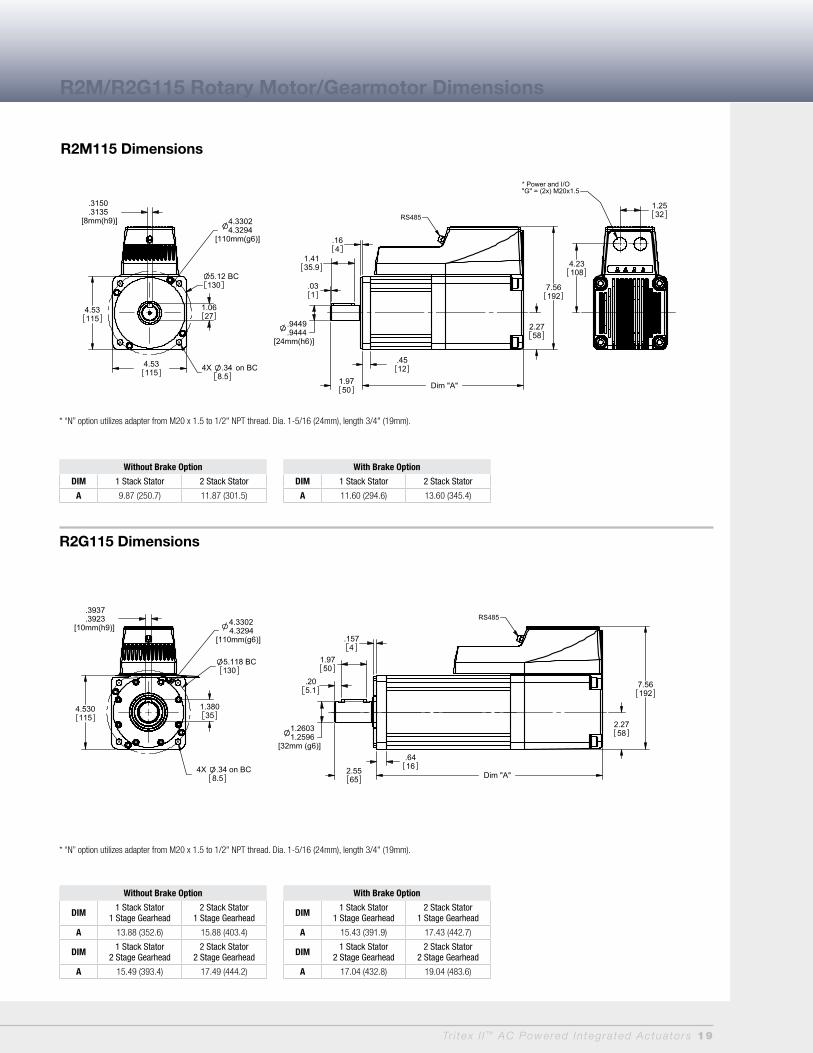
Tr i tex I I ™ AC Powered In tegra ted Actua to rs 19
4.530115
.3937
.3923[10mm(h9)]
4X .34 on BC8.5
4.33024.3294
[110mm(g6)]
5.118 BC130
1.38035
1.26031.2596
[32mm (g6)]
2.5565 Dim "A"
7.56192
2.2758
.205.1
1.9750
.6416
.1574
RS485
4.53115
.3150
.3135[8mm(h9)] 4.3302
4.3294[110mm(g6)]
4X .34 on BC8.5
5.12 BC130
1.0627
4.53115
Dim "A"1.9750
.9449
.9444[24mm(h6)]
1.4135.9
.164
.031
2.2758
7.56192
.4512
RS485
1.2532
4.23108
* Power and I/O"G" = (2x) M20x1.5
R2M115 Dimensions
R2G115 Dimensions
* “N” option utilizes adapter from M20 x 1.5 to 1/2" NPT thread. Dia. 1-5/16 (24mm), length 3/4" (19mm).
* “N” option utilizes adapter from M20 x 1.5 to 1/2" NPT thread. Dia. 1-5/16 (24mm), length 3/4" (19mm).
Without Brake Option
DIM 1 Stack Stator 2 Stack Stator
A 9.87 (250.7) 11.87 (301.5)
Without Brake Option
DIM 1 Stack Stator1 Stage Gearhead
2 Stack Stator1 Stage Gearhead
A 13.88 (352.6) 15.88 (403.4)
DIM 1 Stack Stator2 Stage Gearhead
2 Stack Stator2 Stage Gearhead
A 15.49 (393.4) 17.49 (444.2)
With Brake Option
DIM 1 Stack Stator1 Stage Gearhead
2 Stack Stator1 Stage Gearhead
A 15.43 (391.9) 17.43 (442.7)
DIM 1 Stack Stator2 Stage Gearhead
2 Stack Stator2 Stage Gearhead
A 17.04 (432.8) 19.04 (483.6)
With Brake Option
DIM 1 Stack Stator 2 Stack Stator
A 11.60 (294.6) 13.60 (345.4)
R2M/R2G115 Rotary Motor/Gearmotor Dimensions
E
C
A
B
D
G H
D
F
20 Tr i tex I I ™ AC Powered In tegra ted Actua to rs
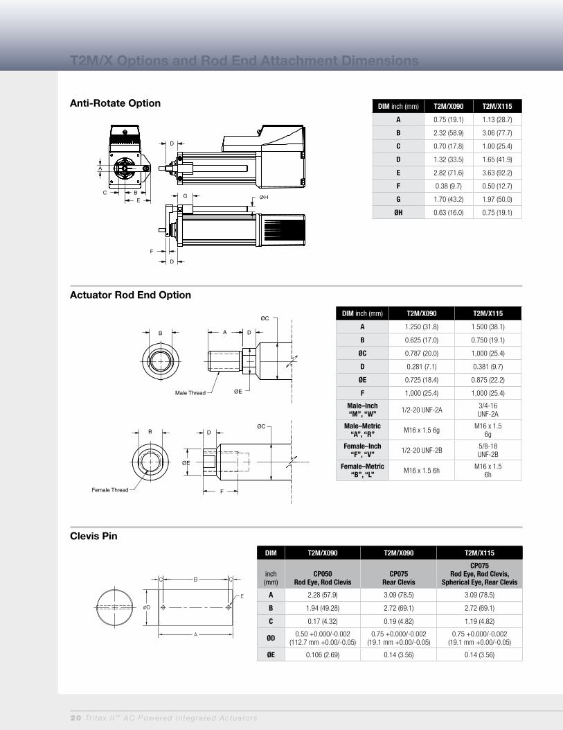
Anti-Rotate Option
Actuator Rod End Option
T2M/X Options and Rod End Attachment Dimensions
Male ThreadFemale Thread
B A D
ØC
ØE
ØCDB
F
ØE
Clevis Pin
DIM inch (mm) T2M/X090 T2M/X115
A 0.75 (19.1) 1.13 (28.7)
B 2.32 (58.9) 3.06 (77.7)
C 0.70 (17.8) 1.00 (25.4)
D 1.32 (33.5) 1.65 (41.9)
E 2.82 (71.6) 3.63 (92.2)
F 0.38 (9.7) 0.50 (12.7)
G 1.70 (43.2) 1.97 (50.0)
ØH 0.63 (16.0) 0.75 (19.1)
DIM T2M/X090 T2M/X090 T2M/X115
inch (mm)
CP050Rod Eye, Rod Clevis
CP075Rear Clevis
CP075Rod Eye, Rod Clevis,
Spherical Eye, Rear Clevis
A 2.28 (57.9) 3.09 (78.5) 3.09 (78.5)
B 1.94 (49.28) 2.72 (69.1) 2.72 (69.1)
C 0.17 (4.32) 0.19 (4.82) 1.19 (4.82)
ØD 0.50 +0.000/-0.002(112.7 mm +0.00/-0.05)
0.75 +0.000/-0.002(19.1 mm +0.00/-0.05)
0.75 +0.000/-0.002(19.1 mm +0.00/-0.05)
ØE 0.106 (2.69) 0.14 (3.56) 0.14 (3.56)
DIM inch (mm) T2M/X090 T2M/X115
A 1.250 (31.8) 1.500 (38.1)
B 0.625 (17.0) 0.750 (19.1)
ØC 0.787 (20.0) 1,000 (25.4)
D 0.281 (7.1) 0.381 (9.7)
ØE 0.725 (18.4) 0.875 (22.2)
F 1,000 (25.4) 1,000 (25.4)
Male–Inch“M”, “W” 1/2-20 UNF-2A 3/4-16
UNF-2A
Male–Metric“A”, “R” M16 x 1.5 6g M16 x 1.5
6g
Female–Inch“F”, “V” 1/2-20 UNF-2B 5/8-18
UNF-2B
Female–Metric“B”, “L” M16 x 1.5 6h M16 x 1.5
6h
Male ThreadFemale Thread
B A D
ØC
ØE
ØCDB
F
ØE

Tr i tex I I ™ AC Powered In tegra ted Actua to rs 21
DIMinch (mm)
T2M/X090 T2M/X115
SRM050 SRM075
A 2.125 (54.0) 2.88 (73.2)
ØB 0.500 (12.7) 0.75 (19.1)
C 1.156 (29.4) 1.72 (43.7)
D 1.312 (33.3) 1.75 (44.5)
E 6 Deg 14 Deg
F 0.500 (12.7) 0.69 (17.5)
G 0.625 (15.9) 0.88 (22.3)
H 0.875 (22.2) 1.13 (28.7)
J 0.750 (19.1) 1.00 (25.4)
K 1/2-20 3/4-16
DIMinch (mm)
T2M/X090 T2M/X115
RCI050 RC075
A 0.750 (19.05) 1.125 (28.58)
B 0.750 (19.05) 1.25 (31.75)
C 1.500 (38.1) 2.375 (60.3)
D 0.500 (12.7) 0.625 (15.88)
E 0.765 (19.43) 1.265 (32.12)
ØF 0.500 (12.7) 0.75 (19.1)
ØG 1.000 (25.4) 1.50 (38.1)
H 1.000 (25.4) 1.25 (31.75)
ØJ N/A 1.25 (31.75)
K 1/2-20 3/4-16
DIMinch (mm)
T2M/X090 T2M/X115
REI050 RE075
ØA 0.50 (12.7) 0.75 (19.05)
B 0.75 (19.05) 1.25 (31.8)
C 1.50 (38.1) 2.06 (52.3)
D 0.75 (19.05) 1.13 (28.7)
E 0.375 (9.53) 0.88 (22.2)
F 1/2-20 3/4-16
T2M/X Rod End Attachment Dimensions
Spherical Rod Eye
Rod Eye
Rod Clevis

22 Tr i tex I I ™ AC Powered In tegra ted Actua to rs
NOTES:
1. EIC 60068-2-64 2.5g, 50-500 Hz. See page 4 for details.
2. Will require external cable for encoder output signals.
3. To achieve -40 operating temperature, specify -XL in the actuator model mask and define Mobilgrease 28 in order notes. Other special lubricants are also available.
Linear Actuator Ordering Guide
Rotary Motor and Gearmotor Ordering Guide
T2M/X = Actuator TypeT2M = Tritex II Linear Actuator, standard
mechanical capacityT2X = Tritex II Linear Actuator, high
mechanical capacity
BBB = Actuator Frame Size090 = 90 mm115 = 115 mm
CC = Stroke Length03 = 3 inch (75 mm) (T2M/X090 only)06 = 6 inch (150 mm)10 = 10 inch (250 mm)12 = 12 inch (305 mm)18 = 18 inch (455 mm)
DD = Lead (linear travel per screw revolution)
01 = 0.1 inch (2.54 mm)02 = 0.2 inch (5.08 mm)05 = 0.5 inch (12.7 mm)08 = 0.75 inch (19.05 mm)
(T2M/X115 only) (5)
E = ConnectionsG = Standard Straight Threaded Port with
Internal terminals, M20 x 1.5N = NPT Threaded Port via Adapter with
Internal Terminals, 1/2" NPTI = Intercontec Style - Exlar std, M16/M23
Style ConnectorX = Custom Connectivity
F = MountingB = Front & Rear FlangeC = Rear Clevis
D = Double Side MountE = Extended Tie RodF = Front FlangeG = Metric Rear ClevisJ = Metric Side MountK = Metric Double Side MountM = Metric Extended Tie RodQ = Metric Side TrunnionR = Rear FlangeS = Side MountT = Side TrunnionX = Special
G = Rod End A = Male Metric Thread (1)B = Female Metric Thread (1)F = Female US Standard Thread (1)L = Female Metric Thread 17-4 SSM = Male US Standard Thread (1) R = Male Metric Thread 17-4 SSV = Female US Standard Thread 17-4 SSW = Male, US Standard Thread 17-4 SSX = Special (please specify)
HH = Feedback TypeHD = Analog Hall DeviceIE = Incremental Encoder, 8192 count
resolutionAF = Absolute Feedback
III-II = Motor Stator, All 8 Pole T2M/X090 Stator Specifications138-40 = 1 Stack, 230 VAC, 4000 rpm238-40 = 2 Stack, 230 VAC, 4000 rpm238-30 = 2 Stack, 230 VAC. 3000 rpm (10)
T2M/X115 Stator Specifications138-30 = 1 Stack, 230 VAC, 3000 rpm238-20 = 2 Stack, 230 VAC, 2000 rpm238-15 = 2 Stack, 230 VAC, 1500 rpm
(N/A with 0.1" lead)
JJJ = Voltage230 = 115-230 VAC, single phase
KKK = Option Board (only 1 selection allowed)
SIO = Standard I/O InterconnectIA4 = SIO plus Isolated 4 - 20 mA Analog I/OEIP = SIO plus Ethernet IPABZ = SIO plus encoder output signal, requires IE Feedback option. Includes M12 connector for encoder output signals. (2)TCP = Modbus TCP
X..XX = Travel and Housing Options (Multiples Possible)
Travel OptionsAR = External Anti-rotatePF = Preloaded Follower (3)L1/2/3 = External Limit Switches (7)RB = Rear BrakeXT = Special Travel Options
Housing OptionsP5 = IP65 Sealed Housing (T2M only)HC = Type III Hard Coat Anodized (4)FG = White Epoxy Coating (4)
Special Motor OptionsHW = Manual Drive Hand Wheel (T2X only)SD = Side Manual DriveHV = High Vibration Option-EIC (9)ET = External Linear Transducer
XL = Special Lubrication (6) XM = Special Motor OptionXH = Special Housing OptionXT = Protective Bellows (N/A with extended
tie rod mounting option)XT = Splined Main Rod (8)
##### = Part Number Designator for Specials
Optional 5 digit assigned PN to designate unique model numbers
R2M/G = Motor TypeR2M = Tritex II AC Rotary MotorR2G = Tritex II AC Rotary Gearmotor
AAA = Frame Size090 = 90 mm115 = 115 mm
BBB = Gear RatioBlank = R2M
Single Reduction Ratios004 = 4:1005 = 5:1010 = 10:1
Double Reduction Ratios016 = 16:1 020 = 20:1025 = 25:1 040 = 40:1050 = 50:1 100 = 100:1
C = Shaft TypeK = KeyedR = Smooth/RoundX = Special Shaft
D = ConnectionsG = Standard Straight Threaded Port with
Internal Terminals, M20 x 1.5N = NPT Threaded Port via Adapter with
Internal Terminals, 1/2" NPTI = Intercontec style - Exlar Standard,
M16/M23 Style ConnectorX = Custom Connectivity
E = Housing OptionsG = Exlar StandardH = Type III Hard Coat AnodizedF = Smooth White Epoxy CoatingE = Electroless Nickel PlatingX = Special or Custom
F = Brake OptionS = No Brake, StandardB = Electric Brake, 24 VDC
GG = Feedback TypeHD = Analog Hall DeviceIE = Incremental Encoder, 8192 Count
Resolution
AF = Absolute Feedback
HHH-HH = Motor StatorsR2M/G090 Stator Specifications238-40 = 2 Stack, 230 VAC, 4000 rpm238-30 = 2 Stack, 230 VAC, 3000 rpm338-20 = 3 Stack, 230 VAC, 2000 rpm
R2M/G115 Stator Specifications138-30 = 1 Stack, 230 VAC, 3000 rpm238-20 = 2 Stack, 230 VAC, 2000 rpm238-15 = 2 Stack, 230 VAC, 1500 rpm
III = Voltage230 = 115-230 VAC, Single Phase
JJJ = Option BoardSIO = Standard I/O InterconnectIA4 = SIO plus Isolated 4-20 mA Analog I/OEIP = SIO plus Ethernet IP =ABZ = SIO plus encoder output signal, requires IE Feedback option. Includes M12 connector for encoder output signals (2) TCP = SIO plus Modbus TCP
XX = Special Options (multiples possible)HW = Manual Drive Handwheel with
Limit SwitchSD = Side Manual DriveHV = High Vibration Option-IEC (1)XH = Special Housing OptionsXM = Special Motor OptionsXL = Special Lubrication (3)
##### = Part Number Designator for Specials
Optional 5 digit assigned PN to designate unique model no.
NOTES: 1. Chrome-plated carbon steel. Threads not
chrome-plated. 2. Will require external cable for encoder
output signals. 3. The dynamic load rating of zero backlash,
preloaded screws is 63% of the dynamic load rating of the std non-preloaded screws. The calculated travel life of a preloaded screw will be 25% of the calculated travel life of the same size and lead of a non-preloaded screw.
4. This housing option may indidate the need for special material main rods or mounting.
5. 0.75 lead not available above 12" stroke. 6. To achieve -40 operating temperature,
specify -XL in the actuator model mask and define Mobilgrease 28 in order notes. Other special lubricants are also available.
7. Limit switch option requires AR option. 8. This option is not sealed and is not
suitable for any environment in which contaminants come in contact with actuator and may enter the actuator.
9. EIC 60068-2-64 2.5g, 50-500 Hz. See page 4 for details.
10. N/A with 0.1" lead
Tritex II AC T2M/X Linear Actuator Ordering Information
Tritex II AC R2M Motor or R2G Gearmotor Ordering Information
T2M/XBBB-CCDD-EFG-HH-III-II-JJJ-KKK- (XX..XX - #####)
R2M/GAAA-BBB-CDEF-GG-HHH-HH-III-JJJ (XX...XX) - #####)
Tr i tex I I ™ AC Powered In tegra ted Actua to rs 23
Tritex II AC Series Cable & Accessories Part No.
“G” Connection Accessories
Nickel plated cable gland- M20 x 1.5 - CE shielding- 2 required GLD-T2M20 x 1.5
Power cable prepared on one end for use with GLD-T2M20 x 1.5 xxx = Length in ft, Standard lengths 015, 025, 050, 075, 100 CBL-T2IPC-RAW-xxx
I/O cable prepared on one end for use with GLD-T2M20 x 1.5 xxx = Length in ft, Standard lengths 015, 025, 050, 075, 100 CBL-T2IOC-RAW-xxx
“N” Connection Accessories
M20 x 1.5 to 1/2" NPT threaded hole adapter for use with conduit ADAPT-M20-NPT1/2
“I” Connection
Power cable with M23 6 pin xxx = Length in feet, std lengths 015, 025, 050, 075, 100 CBL-T2IPC-SMI-xxx
I/O cable with M16 19 pin xxx = Length in feet, std lengths 015, 025, 050, 075, 100 CBL-T2IOC-SMI-xxx
Communications Accessories - Tritex uses a 4 pin M8 RS485 communications connector
Recommended PC to Tritex communications cable-USB/RS485 to M8 connector - xxx = Length in feet, 006 or 015 only CBL-T2USB485-M8-xxx
Multi-Drop RS485 Accessories
RS485 splitter - M8 Pin plug to double M8 Socket receptacle TT485SP
Multidrop Communications Cable M8 to M8 for use with TT485SP/RS485 splitter - xxx = Length in feet, 006 or 015 only CBL-TTDAS-xxx
Multi-Purpose Communications Accessories for long runs, requires terminal block interconnections
USB to RS485 convertor/cable - USB to RS485 flying leads - xxx = Length in feet, 006 or 015 only CBL-T2USB485-xxx
Communications cable M8 to flying leads cable xxx = Length in feet, Standard lengths 015, 025, 050, 075, 100 CBL-TTCOM-xxx
Option Board Cables
EIP and TCP option Ethernet cable - M12 to RJ45 cable xxx = Length in feet, standard lengths 015, 025, 050, 075, 100 CBL-T2ETH-R45-xxx
ABZ option cable - M12 to flying leads 8 wire encoder output cable xxx = Length in feet, standard lengths 015, 025, 050, 075, 100 CBL-T2ENC-xxx
Electrical Accessories
Dynamic Braking Resistor - 100W47Ohm T2BR1
Replacement -AF Battery - used for absolute feedback option T2BAT1
Replacement Normally Closed External Limit Switch (Turck Part number BIM-UNT-RP6X) 43404
Replacement Normally Open External Limit Switch (Turck Part number BIM-UNT-AP6X) 43403
Mechanical Accessories
Clevis Pin for T2M/X090 male “M” rod end 1/2-20 thread CP050
Clevis Pin for T2M/115 male “M” rod end 3/4-16 thread CP075
Spherical Rod Eye for T2M/X090 male “M” rod end 1/2-20 thread SRM050
Spherical Rod Eye for T2M/X115 male “M” rod end 3/4-16 thread SRM075
Rod Eye for T2M/X090 male “M” rod end 1/2-20 thread REI050
Rod Eye for T2M/X115 male “M” rod end 3/4-16 thread RE075
Rod Clevis for T2M/X090 male “M” rod end 1/2-20 thread RCI050
Rod Clevis for T2M/X115 male “M” rod end 3/4-16 thread RC075
Jam Nut for T2M/X090 male rod end, 1/2 - 20 JAM1/2-20-SS
Jam Nut for T2M/X115 male rod end, 3/4-16 JAM3/4-16-SS
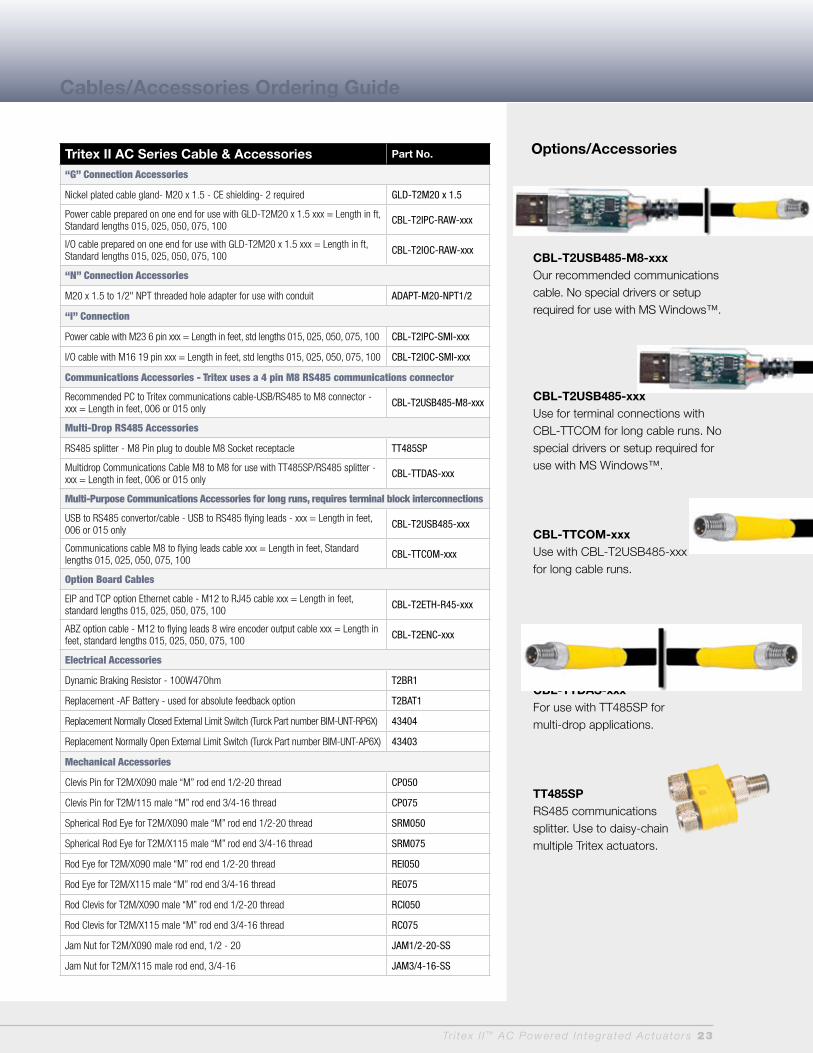
Cables/Accessories Ordering Guide
Options/Accessories
CBL-T2USB485-M8-xxxOur recommended communications cable. No special drivers or setup required for use with MS Windows™.
CBL-T2USB485-xxxUse for terminal connections with CBL-TTCOM for long cable runs. No special drivers or setup required for use with MS Windows™.
CBL-TTCOM-xxxUse with CBL-T2USB485-xxx for long cable runs.
CBL-TTDAS-xxxFor use with TT485SP for multi-drop applications.
TT485SPRS485 communicationssplitter. Use to daisy-chain multiple Tritex actuators.

Copyright 2011, Exlar Corporation 10/11-10,000 PN 50111
Headquartered at our manufacturing and motion control research center in suburban Minneapolis, MN, Exlar serves a global customer base with an extensive standard product line and complete engineering support for custom applications.
Exlar provides sales and support world-wide. To find your local representative, visit our website at www.exlar.com or call our headquarters at 952-500-6200.
Exlar Corporation18400 West 77th StreetChanhassen, MN 55317
TEL: 952.500.6200Toll FREE in US and Canada: 855.620.6200General FAX: 952.368.4877Order Only FAX: 952.368.4359
www.exlar.com
Request a free copy of our literature by calling 952-500-6200 or
download the pdf at www.exlar.com. In addition to the 2011 Product
Catalog, brochures are available on Exlar’s component roller screws and
Tritex or Tritex II Actuators with Embedded Electronics. Process control
and defense industry brochures are also available.
Visit tritex2.com For moreinformation