triple offset valve - nightwine ohio · tritork triple offset valve is a next generation high-end,...
TRANSCRIPT

Triple Offset Valve

In a short period of 25 years, Virgo Group of
companies has gained a position of prominence in
the field of process ball valves, pipeline ball valves
and automation systems for a host of applications in
chemical, petrochemical, oil & gas, fertilizer and
pharmaceutical industries.
During this period, Virgo established its presence in
India, United States of America, Middle East, Far
East and Europe. Today, Virgo is a true multinational
company with manufacturing plants in India, Italy,
Germany and USA, sales offices in seven countries
and customers in over seventy countries.
About us
Virgo valves are designed and manufactured using
the latest engineering softwares and tools like Pro / ® ®Engineer for 3D CAD, ANSYS for finite element
®analysis, Mathcad for engineering calculations & ®Windchill for project & data management.
State-of-the-art manufacturing technologies, modern
quality management methods and competent ERP
system ensure efficient production process resulting
in consistent high quality standard over large
quantities of valves.
TriTork Triple Offset Valve is a next generation high-
end, quarter turn, metal to metal sealing, zero
leakage valve which offers flow control solutions for
varied range of applications.
Products are developed using Finite Element Analysis
2
TriTork Triple Offset Valve
Product Information : Valve Series | Design Features | Range | Options | Applications
Triple Offset Principle
2
3
1
Shaft
axis
Cone
axis
Valve Series Range
• Double flanged (Short Pattern) - TTF • 3" to 56" and larger sizes
• Double flanged (Long Pattern) - TTG • Pressure rating ASME class : 150 / 300 / 600 / 900
• Lug - TTL • Temperature range : -196° C to +815° C
Design Features Options
• ‘ZERO’ leakage • Live loaded shaft seal
• Metal to metal sealing • Extended bonnet for low temperature and
Cryogenic applications• Low operating torque
• High temperature configuration • Inherently fire safe
• Steam jacketing • One piece shaft with blow-out proof design
• Adjustable shaft seal for low emission
• Bearing seals
• NACE compliance
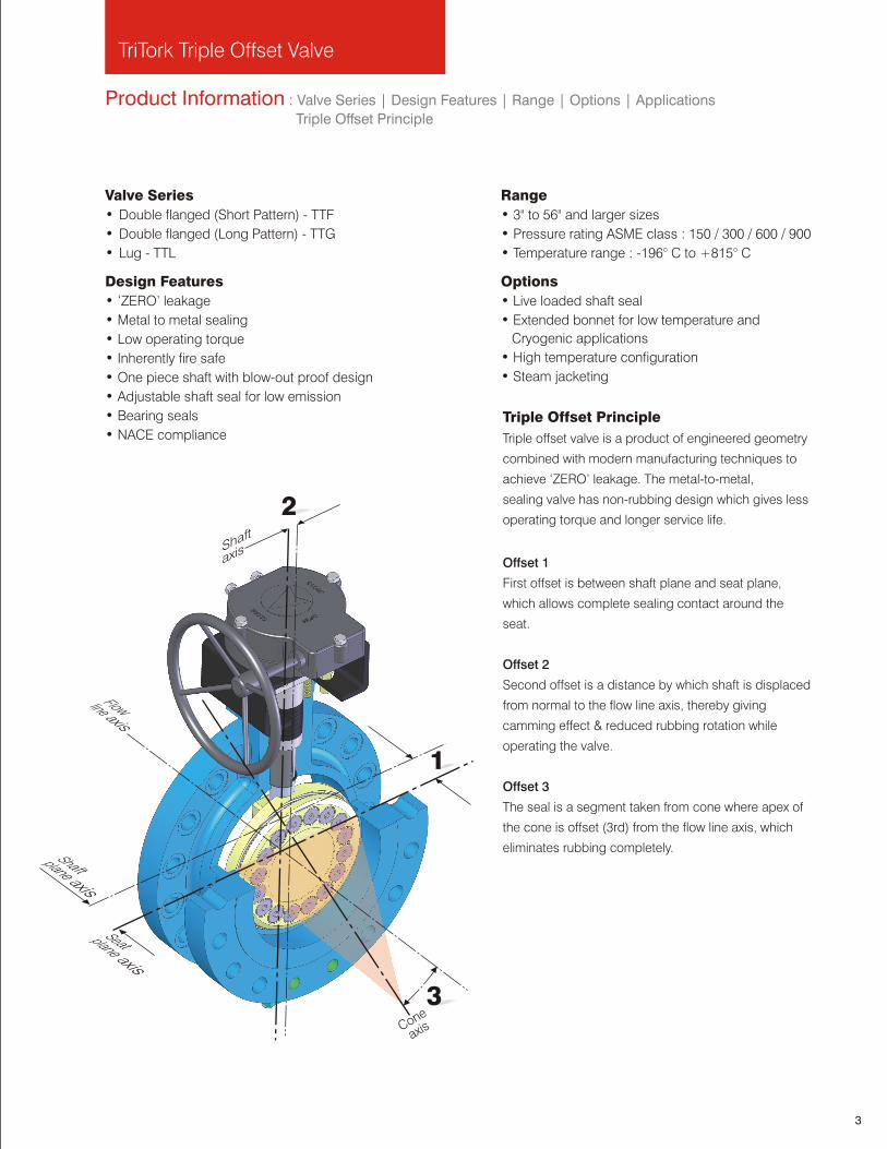
Triple Offset Principle
Triple offset valve is a product of engineered geometry
combined with modern manufacturing techniques to
achieve ‘ZERO’ leakage. The metal-to-metal,
sealing valve has non-rubbing design which gives less
operating torque and longer service life.
Offset 1
First offset is between shaft plane and seat plane,
which allows complete sealing contact around the
seat.
Offset 2
Second offset is a distance by which shaft is displaced
from normal to the flow line axis, thereby giving
camming effect & reduced rubbing rotation while
operating the valve.
Offset 3
The seal is a segment taken from cone where apex of
the cone is offset (3rd) from the flow line axis, which
eliminates rubbing completely.
3
Product Information : Major Applications | Reference Standards | Seat Leakage Comparison
Reference Standards
Design and Manufacturing API 609, ASME B16.34
Face to Face / End to End API 609, ASME B16.10, ISO 5752 Series 13, ISO 5752 Series 14
End Connection ASME B16.5 for flanged end upto 24”/ASME B16.47 for larger sizes
Testing API 598 Ninth Edition
Fire Test API 607 Fifth Edition, June 2005 / ISO 10497-5:2004, API 6FA
Fugitive Emission Testing MESC 77/312, ISO15848
Material Conformance NACE MR 01-75
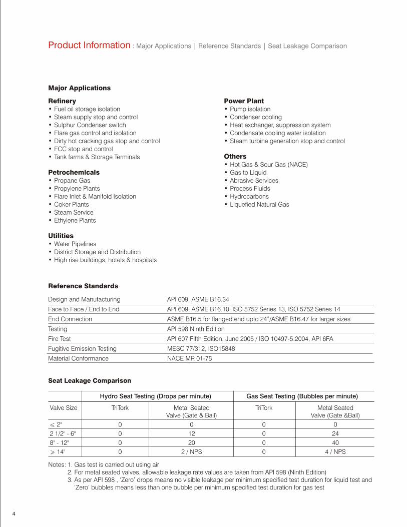
Notes: 1. Gas test is carried out using air2. For metal seated valves, allowable leakage rate values are taken from API 598 (Ninth Edition)3. As per API 598 , ‘Zero’ drops means no visible leakage per minimum specified test duration for liquid test and
‘Zero’ bubbles means less than one bubble per minimum specified test duration for gas test
Hydro Seat Testing (Drops per minute) Gas Seat Testing (Bubbles per minute)
Valve Size TriTork Metal Seated TriTork Metal Seated Valve (Gate & Ball) Valve (Gate &Ball)
< 2" 0 0 0 0
2 1/2" - 6" 0 12 0 24
8" - 12" 0 20 0 40
> 14" 0 2 / NPS 0 4 / NPS
Major Applications
Refinery Power Plant• Fuel oil storage isolation • Pump isolation
• Steam supply stop and control • Condenser cooling
• Sulphur Condenser switch • Heat exchanger, suppression system
• Flare gas control and isolation • Condensate cooling water isolation
• Dirty hot cracking gas stop and control • Steam turbine generation stop and control
• FCC stop and controlOthers• Tank farms & Storage Terminals• Hot Gas & Sour Gas (NACE)
Petrochemicals • Gas to Liquid
• Propane Gas • Abrasive Services
• Propylene Plants • Process Fluids
• Flare Inlet & Manifold Isolation • Hydrocarbons
• Coker Plants • Liquefied Natural Gas
• Steam Service
• Ethylene Plants
Utilities• Water Pipelines
• District Storage and Distribution
• High rise buildings, hotels & hospitals
Seat Leakage Comparison
4
1
82
34
6
9
10
12
14
11
7
9
19
21
20
23
22
24
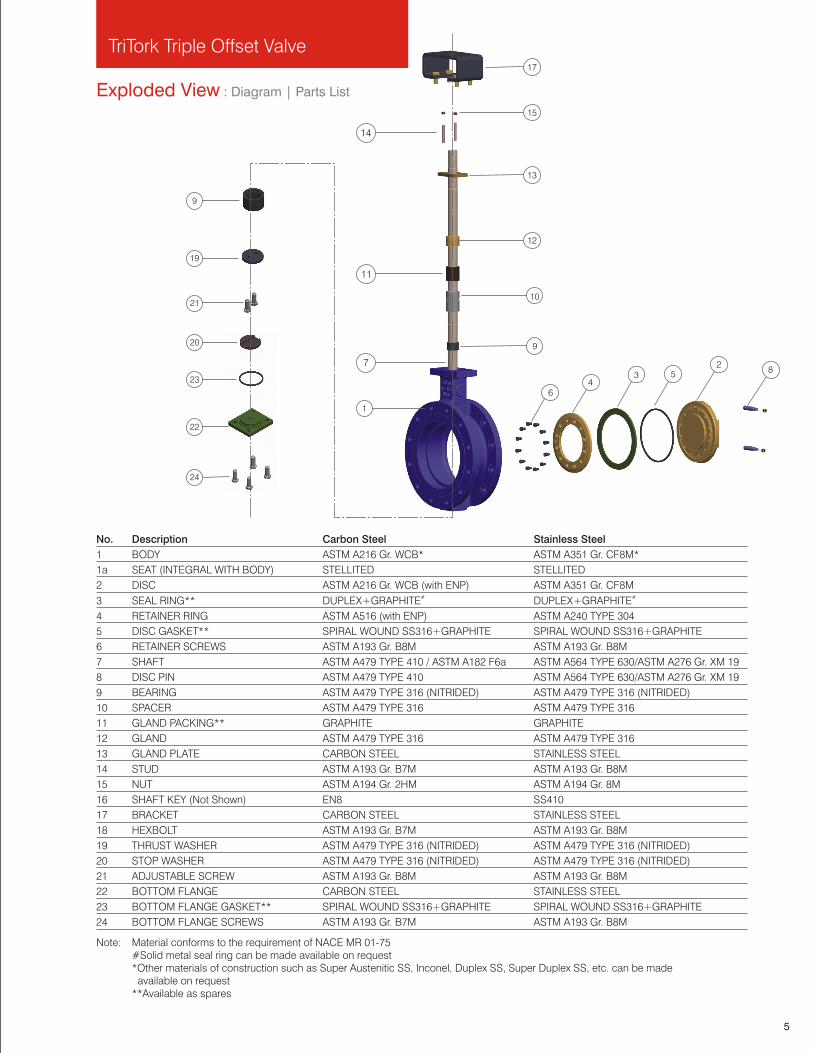
No. Description Carbon Steel Stainless Steel
1 BODY ASTM A216 Gr. WCB* ASTM A351 Gr. CF8M*
1a SEAT (INTEGRAL WITH BODY) STELLITED STELLITED
2 DISC ASTM A216 Gr. WCB (with ENP) ASTM A351 Gr. CF8M# #3 SEAL RING** DUPLEX+GRAPHITE DUPLEX+GRAPHITE
4 RETAINER RING ASTM A516 (with ENP) ASTM A240 TYPE 304
5 DISC GASKET** SPIRAL WOUND SS316+GRAPHITE SPIRAL WOUND SS316+GRAPHITE
6 RETAINER SCREWS ASTM A193 Gr. B8M ASTM A193 Gr. B8M
7 SHAFT ASTM A479 TYPE 410 / ASTM A182 F6a ASTM A564 TYPE 630/ASTM A276 Gr. XM 19
8 DISC PIN ASTM A479 TYPE 410 ASTM A564 TYPE 630/ASTM A276 Gr. XM 19
9 BEARING ASTM A479 TYPE 316 (NITRIDED) ASTM A479 TYPE 316 (NITRIDED)
10 SPACER ASTM A479 TYPE 316 ASTM A479 TYPE 316
11 GLAND PACKING** GRAPHITE GRAPHITE
12 GLAND ASTM A479 TYPE 316 ASTM A479 TYPE 316
13 GLAND PLATE CARBON STEEL STAINLESS STEEL
14 STUD ASTM A193 Gr. B7M ASTM A193 Gr. B8M
15 NUT ASTM A194 Gr. 2HM ASTM A194 Gr. 8M
16 SHAFT KEY (Not Shown) EN8 SS410
17 BRACKET CARBON STEEL STAINLESS STEEL
18 HEXBOLT ASTM A193 Gr. B7M ASTM A193 Gr. B8M
19 THRUST WASHER ASTM A479 TYPE 316 (NITRIDED) ASTM A479 TYPE 316 (NITRIDED)
20 STOP WASHER ASTM A479 TYPE 316 (NITRIDED) ASTM A479 TYPE 316 (NITRIDED)
21 ADJUSTABLE SCREW ASTM A193 Gr. B8M ASTM A193 Gr. B8M
22 BOTTOM FLANGE CARBON STEEL STAINLESS STEEL
23 BOTTOM FLANGE GASKET** SPIRAL WOUND SS316+GRAPHITE SPIRAL WOUND SS316+GRAPHITE
24 BOTTOM FLANGE SCREWS ASTM A193 Gr. B7M ASTM A193 Gr. B8M
Note: Material conforms to the requirement of NACE MR 01-75#Solid metal seal ring can be made available on request*Other materials of construction such as Super Austenitic SS, Inconel, Duplex SS, Super Duplex SS, etc. can be made available on request**Available as spares
Exploded View : Diagram | Parts List
TriTork Triple Offset Valve
5
5
13
15
17

TriTork Triple Offset Valve
Design Features : Low Emission Shaft Seal | Metal to Metal 'ZERO' Leakage
Externally Retained Blow-Out Proof Design
Standard MountingBracket top side drilling and shaft connection as per ISO 5211.
Low Emission Shaft SealAdjustable shaft packing with multiple graphite rings sandwiched between two anti-extrusion rings control fugitive emission and gives longer packing life. Gland packing with live loading is available as an option.
Externally Retained Blow-Out Proof DesignEngineered gland design gives shaft blow out proof protection externally, conforming to the requirements of API 609. In addition, two screws provided at the bottom retain the shaft against blowout.
External Indicator for Disc PositionDisc position is accomplished by dimple on shaft. When the dimple is inline with flow axis, disc is open.
Design Features : Standard Mounting | External Indicator for Disc Position
Bearing Protection | One-Piece Shaft
Metal to Metal 'ZERO' leakageLaminated resilient seal ring flexes to give uniform wedging effect and ensures 'ZERO' leakage. Resiliency of seal ring allows small deformation in body for temperature fluctuations without risk of jamming. Seal ring is retained by retainer ring and bolting. Gasket behind seal ring ensures leak proof joint.
Integral Stellited Seat
Duplex SS Laminated Seal Ring
Body
Disc Gasket
DiscRetainer Ring
One-Piece ShaftOne-piece shaft is guided by long bearings, which are placed nearer to disc for close support. Bearings are super finished and nitrided for trouble free life. All portion of the shaft within the pressure boundary exceed in strength compare to the shaft portion outside the pressure boundary by minimum 10%.
Bearing ProtectionGraphite ring encased in bearing ensures protection against ingress of line media in to the bearing surface and thus avoids jamming of shaft.
6 7
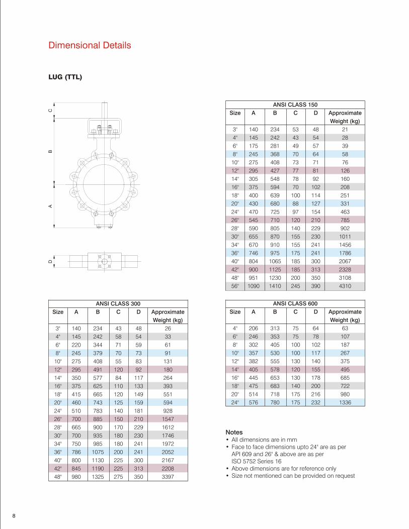
Dimensional Details
Notes •• Face to face dimensions upto 24" are as per
API 609 and 26" & above are as per ISO 5752 Series 16
• Above dimensions are for reference only• Size not mentioned can be provided on request
All dimensions are in mm
LUG (TTL)
8
BA
CD
ANSI CLASS 300
Size A B C D Approximate
Weight (kg)
3" 140 234 43 48 26
4" 145 242 58 54 33
6" 220 344 71 59 61
8" 245 379 70 73 91
10" 275 408 55 83 131
12" 295 491 120 92 180
14" 350 577 84 117 264
16" 375 625 110 133 393
18" 415 665 120 149 551
20" 460 743 125 159 594
24" 510 783 140 181 928
26" 700 885 150 210 1547
28" 665 900 170 229 1612
30" 700 935 180 230 1746
34" 750 985 180 241 1972
36" 786 1075 200 241 2052
40" 800 1130 225 300 2167
42" 845 1190 225 313 2208
48" 980 1325 275 350 3397
ANSI CLASS 600
Size A B C D Approximate
Weight (kg)
4" 206 313 75 64 63
6" 246 353 75 78 107
8" 302 405 100 102 187
10" 357 530 100 117 267
12" 382 555 130 140 375
14" 405 578 120 155 495
16" 445 653 130 178 685
18" 475 683 140 200 722
20" 514 718 175 216 980
24" 576 780 175 232 1336
ANSI CLASS 150
Size A B C D Approximate
Weight (kg)
3" 140 234 53 48 21
4" 145 242 43 54 28
6" 175 281 49 57 39
8" 245 368 70 64 58
10" 275 408 73 71 76
12" 295 427 77 81 126
14" 305 548 78 92 160
16" 375 594 70 102 208
18" 400 639 100 114 251
20" 430 680 88 127 331
24" 470 725 97 154 463
26" 545 710 120 210 785
28" 590 805 140 229 902
30" 655 870 155 230 1011
34" 670 910 155 241 1456
36" 746 975 175 241 1786
40" 804 1065 185 300 2067
42" 900 1125 185 313 2328
48" 951 1230 200 350 3108
56" 1090 1410 245 390 4310
TriTork Triple Offset Valve
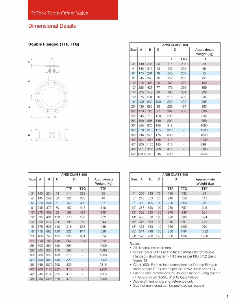
Dimensional Details
Notes• mm
• Class 150 & 300: Flanged - short pattern (TTF) are as per ISO 5752 Basic Series 13
• Class 600: Face to face dimensions for Double Flanged - short pattern (TTF) are as per ISO 5752 Basic Series 14
• Face to face dimensions for Double Flanged - long pattern (TTG) are as per ASME B16.10 Gate Valves
• Above dimensions are for reference only• Size not mentioned can be provided on request
All dimensions are in
Face to face dimensions for Double
Double Flanged (TTF, TTG)
9
ANSI CLASS 150
Size A B C D Approximate
Weight (kg)
TTF TTG TTF
3" 140 234 53 114 203 29
4" 145 242 43 127 229 38
6" 175 281 49 140 267 55
8" 245 368 70 152 292 82
10" 275 408 73 165 330 109
12" 295 427 77 178 356 169
14" 305 548 78 190 381 208
16" 375 594 70 216 406 245
18" 400 639 100 222 432 285
20" 430 680 88 229 457 363
24" 470 725 97 267 508 506
26" 545 710 120 292 – 834
28" 590 805 140 292 – 950
30" 655 870 155 318 – 1080
34" 670 910 155 326 – 1500
36" 746 975 175 330 – 1830
40" 804 1065 185 410 – 2130
42" 900 1125 185 410 – 2394
48" 951 1230 200 470 – 3180
56" 1090 1410 245 530 – 4546
DA
BC
ANSI CLASS 300
Size A B C D Approximate
Weight (kg)
TTF TTG TTF
3" 140 234 43 114 282 35
4" 145 242 58 127 305 48
6" 220 344 71 140 403 87
8" 245 379 70 152 418 118
10" 275 408 55 165 457 145
12" 295 491 120 178 502 222
14" 350 577 84 190 762 344
16" 375 625 110 216 838 435
18" 415 665 120 222 914 588
20" 460 743 125 229 991 674
24" 510 783 140 267 1143 979
26" 700 885 150 292 - 1600
28" 665 900 170 292 - 1680
30" 700 935 180 318 - 1800
34" 750 985 180 326 - 2002
36" 786 1075 200 330 - 2115
40" 800 1130 225 410 - 2220
42" 845 1190 225 410 - 2265
48" 980 1325 275 470 - 3450
ANSI CLASS 600
Size A B C D Approximate
Weight (kg)
TTF TTG TTF
4" 206 313 75 190 432 82
6" 246 353 75 210 559 143
8" 302 405 100 230 660 245
10" 357 530 100 250 787 345
12" 382 555 130 270 838 501
14" 405 578 120 290 889 594
16" 445 653 130 310 991 745
18" 475 683 140 330 1092 910
20" 514 718 175 350 1194 1282
24" 576 780 175 390 1397 1730

10
Technical Details : Shaft Side Torque Values | Pressure-Temperature Rating | Typical Flow Characteristics
Shaft Side Torque Values
Pressure-Temperature Rating (As per ASME B16.34)
1600
1400
1200
1000
800
600
400
200
0100 200 300 400 500 600 700 800 900 1000
0 Temperature ( F)
Pre
ssu
re (P
SI)
WCB # 600
CF8M # 600
WCB # 300
CF8M # 300
WCB # 150
CF8M # 150
Notes • Torque values are for laminated duplex + graphite seal ring and stellited seat• Torque values are at ambient temperature with media being clear water and without factor of safety • Consider factor of safety as 30% on above mentioned torque values• Contact factory for disc side torque values
Typical Flow Characteristics
4020
120
100
80
40
20
00 10080
60
60
% o
f M
axi
mu
m C
v
% of Disc Opening
Size ANSI # 150 ∆P 20 bar ANSI # 300 P 50 bar ANSI # 600 P 100 bar
(NPS) Opening Closing Running Opening Closing Running Opening Closing Running
Nm in-lbs Nm in-lbs Nm in-lbs Nm in-lbs Nm in-lbs Nm in-lbs Nm in-lbs Nm in-lbs Nm in-lbs
3" 75 662 68 606 41 363 130 1152 115 1018 62 549 -- -- -- – – –
4" 112 994 108 955 46 407 201 1779 194 1717 74 655 592 5240 406 3593 164 1452
6" 197 1741 181 1601 49 434 448 3965 335 2965 145 1283 1444 12780 589 5213 311 2753
8" 359 3178 245 2168 90 797 879 7780 511 4522 279 2469 2521 22313 1456 12887 526 4655
10" 642 5685 468 4142 146 1292 1492 13205 909 8045 352 3115 4375 38722 2153 19056 643 5691
12" 969 8580 638 5646 184 1629 2159 19109 1278 11311 451 3992 6389 56547 2946 26074 915 8098
14" 1284 11368 772 6832 246 2177 2701 23906 1550 13718 551 4877 7611 67363 3614 31987 1123 9939
16" 1797 15902 1050 9293 291 2576 4633 41006 1945 17214 782 6921 11256 99624 4156 36784 1444 12780
18" 2360 20891 1208 10692 366 3239 5273 46670 2466 21825 906 8019 20508 181511 6536 57849 3858 34146
20" 2859 25300 1430 12656 397 3514 6856 60681 2637 23339 1198 10603 26345 233173 8870 78506 4973 44015
24" 4583 40565 2450 21684 520 4602 10654 94296 4402 38961 1456 12887 35603 315113 9558 84595 8010 70895
26" 11753 104022 4198 37152 2350 20797 35522 314366 16259 143895 7104 125747 – – – – – –
28" 15710 139033 7024 62162 3142 27806 52242 462343 24207 214235 10448 184937 – – – – – –
30" 18975 167928 8911 78862 3794 33576 57785 511401 34188 302566 11557 204560 – – – – – –
34" 21812 193036 9437 83517 4362 38603 70159 620907 38807 343444 14031 248363 – – – – – –
36" 29460 260721 13476 119262 5892 52044 91230 807382 54099 478775 18246 322953 – – – – – –
40" 40540 358779 16961 150104 8108 71755 111064 982915 58128 514434 22212 393166 – – – – – –
42" 45514 402798 20664 182876 9102 80552 131625 982915 67318 514434 26325 393166 – – – – – –
48" 62466 552824 24986 221126 12087 106969 193309 1710788 94619 837380 38661 684315 – – – – – –
56" 87199 771711 35924 317827 17439 154335 – – – – – – – – – – – –
∆ ∆
TriTork Triple Offset Valve
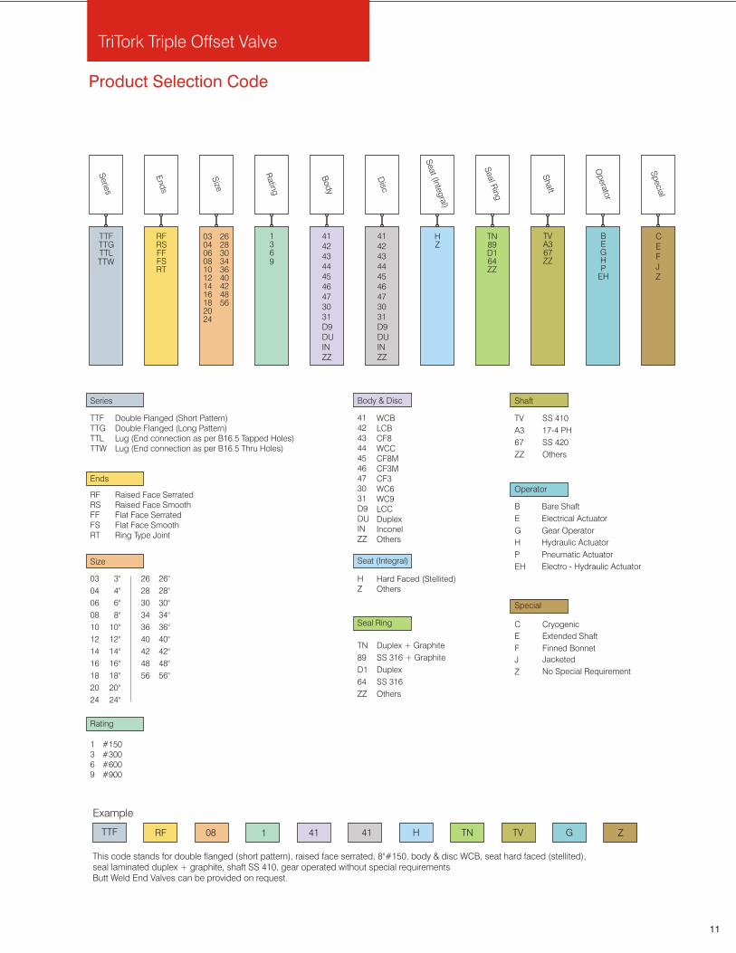
Product Selection Code
TTF RF 08 1 41 41
Example
Operator
B Bare Shaft
Special
Shaft
TV SS 410
A3 17-4 PH
67 SS 420
ZZ Others
Body & Disc
WCBLCBCF8WCCCF8MCF3MCF3WC6WC9LCCDuplexInconelOthers
Seat (Integral)
HZ
Hard Faced (Stellited)Others
Seal Ring
TN Duplex + Graphite
89 SS 316 + Graphite
D1 Duplex
64 SS 316
ZZ Others
Rating
1369
#150#300#600#900
This code stands for double flanged (short pattern), raised face serrated, 8"#150, body & disc WCB, seat hard faced (stellited),seal laminated duplex + graphite, shaft SS 410, gear operated without special requirementsButt Weld End Valves can be provided on request.
TTFTTGTTL
Series
CEFJZ
Sp
ecial
BEGHP
EH
Op
erato
r
TVA367ZZ
Shaft
TN89D164ZZ
Sea
l Rin
gHZ
Sea
t (Integ
ral)
Bod
y
1369
Ratin
g
RFRSFFFSRT
End
s
11
E Extended Shaft
F Finned Bonnet
J Jacketed
C Cryogenic
Z No Special Requirement
0304060810121416182024
Size
262830343640424856
Ends
RFRSFFFSRT
Raised Face SerratedRaised Face SmoothFlat Face Serrated Flat Face SmoothRing Type Joint
Size
Series
TTFTTG TTL TTW
Double Flanged (Short Pattern)Double Flanged (Long Pattern)Lug (End connection as per B16.5 Tapped Holes)Lug (End connection as per B16.5 Thru Holes)
03 3"
04 4"
06 6"
08 8"
10 10"
12 12"
14 14"
16 16"
18 18"
20 20"
24 24"
26
28
30
34
36
40
42
48
26"
28"
30"
34"
36"
40"
42"
48"
56 56"
Disc
E Electrical Actuator
G Gear Operator
H Hydraulic Actuator
P Pneumatic Actuator
EH Electro - Hydraulic Actuator
H TN TV ZG
414243444546473031D9DUINZZ
TTW
414243444546473031D9DUINZZ
414243444546473031D9DUINZZ

Technical specifications are subject to changeTOV: 2011/12 R6
Virgo Engineers Group
www.tritork.comwww.virgoengineers.com
Europe
VIA Sicilia, 96 20020, Magnago Milan, ItalyPhone: +39 0331 308211Fax: +39 0331 306299
Virgo Europe Spa
North and South America
10225 Mula Road, Suite 130 Stafford, TX – 77477, USAPhone: +1 281 933 3100Fax: +1 281 933 3110
Virgo Engineers Inc.
Indian Sub-continent
277, Hinjewadi Phase II, Maan (Mulshi),Pune - 411 057, IndiaPhone: +91 20 6674 4000Fax: +91 20 66744021
Virgo Engineers LimitedMiddle East and Africa
Unit - R/A08-YA03/04, Jebel Ali Free Zone,P.O. Box : 18748, Dubai - UAEPhone: +971-4-887 6697Fax: +971-4-887 6698
Virgo Valves & Controls (ME) FZE
Far East Asia
Suite 1904, 19th Floor, Kenanga International, Jalan Sultan Ismail, 50250 Kuala Lumpur, Malaysia.Phone: +60 3 2161 8260Fax: +60 3 2166 6489
Virgo Valves & Controls Limited
Contact us:[email protected]
Division
South Korea
1556, 15th Floor Sam-Chang Plaza Bldg. 173,Dohwa-dong, Mapo-gu, Seoul South KoreaMobile: +82 10905 69327Fax: +1 281 933 3110
Virgo Valves & Controls Korea Ltd,
Indian Sub-continent
J-525/160 MIDC, Bhosari,Pune - 411 026, IndiaPhone: +91 20 6612 1900Fax: +91 20 6611 7811
Virgo Engineers Limited
China
Room No. C 38, 11th Floor, Shanghai Mart, 2299, Yan An Road (W), Shanghai, China – 200336.Phone: +86 21 6207 6626Fax: +86 21 6207 6626
Virgo Engineers Limited