treatment technology summary for critical pollutants of
TRANSCRIPT

Treatment Technology Summary for Critical Pollutants of Concern in Power Plant Wastewaters
1012549

ELECTRIC POWER RESEARCH INSTITUTE 3420 Hillview Avenue, Palo Alto, California 94304-1338 • PO Box 10412, Palo Alto, California 94303-0813 • USA
800.313.3774 • 650.855.2121 • [email protected] • www.epri.com
Treatment Technology Summary for Critical Pollutants of Concern in Power Plant Wastewaters
1012549
Technical Update, January 2007
EPRI Project Manager
P. Chu

DISCLAIMER OF WARRANTIES AND LIMITATION OF LIABILITIES
THIS DOCUMENT WAS PREPARED BY THE ORGANIZATION(S) NAMED BELOW AS AN ACCOUNT OF WORK SPONSORED OR COSPONSORED BY THE ELECTRIC POWER RESEARCH INSTITUTE, INC. (EPRI). NEITHER EPRI, ANY MEMBER OF EPRI, ANY COSPONSOR, THE ORGANIZATION(S) BELOW, NOR ANY PERSON ACTING ON BEHALF OF ANY OF THEM:
(A) MAKES ANY WARRANTY OR REPRESENTATION WHATSOEVER, EXPRESS OR IMPLIED, (I) WITH RESPECT TO THE USE OF ANY INFORMATION, APPARATUS, METHOD, PROCESS, OR SIMILAR ITEM DISCLOSED IN THIS DOCUMENT, INCLUDING MERCHANTABILITY AND FITNESS FOR A PARTICULAR PURPOSE, OR (II) THAT SUCH USE DOES NOT INFRINGE ON OR INTERFERE WITH PRIVATELY OWNED RIGHTS, INCLUDING ANY PARTY'S INTELLECTUAL PROPERTY, OR (III) THAT THIS DOCUMENT IS SUITABLE TO ANY PARTICULAR USER'S CIRCUMSTANCE; OR
(B) ASSUMES RESPONSIBILITY FOR ANY DAMAGES OR OTHER LIABILITY WHATSOEVER (INCLUDING ANY CONSEQUENTIAL DAMAGES, EVEN IF EPRI OR ANY EPRI REPRESENTATIVE HAS BEEN ADVISED OF THE POSSIBILITY OF SUCH DAMAGES) RESULTING FROM YOUR SELECTION OR USE OF THIS DOCUMENT OR ANY INFORMATION, APPARATUS, METHOD, PROCESS, OR SIMILAR ITEM DISCLOSED IN THIS DOCUMENT.
ORGANIZATION(S) THAT PREPARED THIS DOCUMENT
Wter Systems Specialists, Inc.
This is an EPRI Technical Update report. A Technical Update report is intended as an informal report of continuing research, a meeting, or a topical study. It is not a final EPRI technical report.
NOTE
For further information about EPRI, call the EPRI Customer Assistance Center at 800.313.3774 or e-mail [email protected].
Electric Power Research Institute, EPRI, and TOGETHER…SHAPING THE FUTURE OF ELECTRICITY are registered service marks of the Electric Power Research Institute, Inc.
Copyright © 2007 Electric Power Research Institute, Inc. All rights reserved.

iii
CITATIONS This document was prepared by
Water Systems Specialists, Inc. 5808 Princeton Avenue N.E. Seattle, Washington 98105
Principal Investigator C. Haussmann T. Wolfe
This document describes research sponsored by the Electric Power Research Institute (EPRI).
This publication is a corporate document that should be cited in the literature in the following manner:
Treatment Technology Summary for Critical Pollutants of Concern in Power Plant Wastewaters. EPRI, Palo Alto, CA: 2007. 1012549.

v
ABSTRACT This report summarizes the most promising technologies available for the removal of aluminum, arsenic, boron, copper, mercury and selenium from power plant FGD wastewaters. Remediation of the high chloride levels in FGD waters is also discussed. The information for this technology summary stems from literature searches, technology supplier and vendor interviews and the authors’ experience in power plant and other wastewater treatment systems. The report lists existing and potential technologies that meet the treatment goals of reducing the pollutants to the levels typically required by NPDES permits.


vii
EXECUTIVE SUMMARY With the ever increasing restrictions of air emissions, coupled with the increasingly stringent water quality requirements of the future NPDES permits anticipated, there is interest in finding air and water treatment technologies that can help the power plant operators meet these dictates.
This report discusses the characterization and treatment options for six pollutants (aluminum, arsenic, boron, copper, mercury, and selenium) found in power plant flue gas desulfurization wastewaters – with the focus on flue gas desulfurization (FGD) wastewater. The information presented is based on an extensive literature survey on the subject as well as on interviews with technology and equipment suppliers plus the authors’ experience with several of the cited technologies. Results of recently conducted industry demonstration tests at several power plant FGD operations are cited.
This technology summary uses the water quality characteristics of wastewaters from an earlier EPRI screening study of eight FGD wastewater samples as a basis. This information is used to assess the impact of the various contaminants on typical and potential treatment technologies. The focus of the summary is on viable technologies that have demonstrated their ability to achieve the pollutant reduction goals that are typically set by governing or future NPDES permitting. Many of the technologies described are presently implemented at existing FGD installations or are likely candidate technologies for future FGD applications.
Due to the severity of the FGD wastewater characteristics and combined with the strict requirements of effluent quality, the remediation schemes typically consist of a series of treatment steps including polishing operations. These process alternatives basically consist of chemical treatment, physical-chemical processes and biological methods. The chemical processes include conventional or iron coprecipitation and inorganic or organo sulfide precipitation for more effective metals removal. Viable physical-chemical methods employ evaporation and adsorption, specialized membrane separations techniques as well as selective ion exchange for heavy metals and boron. The biological approach that has shown the biggest success in reducing FGD wastewater metals, including selenate, utilizes specialized bacteria in an anaerobic environment. Passive treatment technologies (i.e. constructed wetlands using specialized enhancements) have also shown to be a viable treatment alternative.
Other technologies such as granular ferric and titanium oxide as well as specialized adsorbents that have shown success in the purification of drinking and municipal wastewaters, acid mine drainage and industrial wastewaters are cited as well. The potential use of electrocoagulation and related technologies are discussed.
The number of treatment systems (for pollutants other than TSS) presently operating on strictly FGD wastewaters is very small. Over the past years, several brine concentrators were installed for processing FGD blowdown streams, but most of these systems are sitting idle. While many of the technologies identified as most suitable for FGD applications are of a relatively state-of-the-art nature, their use with the complex and concentrated FGD wastewaters is new. The amount of data and experience for these types of applications is limited.


ix
GLOSSARY OF TERMS Term Description
AA Activated Alumina
AB Applied Biosciences Corporation
ABMet Proprietary Biological Process by Zenon/Applied Biosciences Corporation
BDAT Best Demonstrated Available Technology
BOD Biological Oxygen Demand
BV Bed Volumes
CCB Coal Combustion Byproduct
CWTS Constructed Wetlands
DBA Dibasic Acids
ED Electro-dialysis
EBCV Empty Bed Contact Volumes
EPA Environmental Protection Agency
EPRI Electric Power Research Institute
ESP Electrostatic Precipitator
FGD Flue Gas Desulfurization
FOG Fats, Oils and Grease
GFH Granular Ferric Hydroxide
GFO Granular Ferric Oxide
GTO Granular Titanium Oxide
HERO High Efficiency Reverse Osmosis
IX Ion Exchange
MCL Maximum Concentration Level
MDL Minimum Detection Limit
MF Micro-filtration
MOB Manganese-Oxidizing Bacteria Beds
MVR Mechanical Vapor Recompression
NF Nano-filtration
NPDES National Priority Discharge Elimination Systems

x
PISCES Power Plant Integrated System Chemical Emissions Study
PCS Permit Compliance System
RAPS Reducing and Alkalinity Producing System
RO Reverse Osmosis
SBR Sulfate Reducing Bacteria
TCLP Toxicity Characteristic Leaching Procedure
TMT Trimercapto-s-triazine, trisodium salt
TDS Total Dissolved Solids
TRI Toxic Release Inventory
TSS Total Suspended Solids
TVR Thermal Vapor Recompression
TWPE Toxic Weight Pounds Equivalent
UF Ultra-filtration
WAC Weak acid cation (ion exchange)
WWTS Wastewater Treatment System
WTE Waste-to-Energy
ZLD Zero Liquid Discharge
ZVI Zero Valence Iron

xi
CONTENTS
1 INTRODUCTION ....................................................................................................................1-1
2 FLUE GAS DESULFURIZATION WASTEWATERS .............................................................2-1 CHEMICAL COMPOSITIONS..............................................................................................2-1 GENERAL FGD WASTEWATER CHARACTERISTICS....................................................2-10
3 POLLUTANTS OF CONCERN...............................................................................................3-1 Aluminum .............................................................................................................................3-1 Arsenic .................................................................................................................................3-1 Boron....................................................................................................................................3-1 Copper .................................................................................................................................3-2 Mercury ................................................................................................................................3-2
Mercury General Description .........................................................................................3-2 Selenium ..............................................................................................................................3-3
Selenium General Description .......................................................................................3-3
4 WASTEWATER TREATMENT TECHNOLOGIES.................................................................4-1 General Concepts ................................................................................................................4-1 Chemical Treatment Processes...........................................................................................4-1 Biological Treatment Systems..............................................................................................4-2 Comprehensive Treatment...................................................................................................4-2
Overview ........................................................................................................................4-2 Technical Challenges.....................................................................................................4-3
Individual Treatment Processes...........................................................................................4-4
5 FGD TREATMENT OPTIONS–RECENT DEVELOPMENTS.................................................5-1 Treatment for Specific Pollutants .........................................................................................5-1
Trace Metals ..................................................................................................................5-1 Treatment Approaches.........................................................................................................5-2 FGD Treatment Experience .................................................................................................5-2
Pleasant Prairie Power Plant .........................................................................................5-2 Clinch River....................................................................................................................5-3
Biological and Passive Treatment........................................................................................5-4 Bioreactor Pilot Programs ..............................................................................................5-4 Passive Treatment System (Constructed Wetlands)......................................................5-5 Other Passive Treatment System Demonstration Programs .........................................5-6 Bioreactor (ABMet®) vs. Passive Treatment Systems...................................................5-8
6 EXISTING TREATMENT PROCESSES.................................................................................6-1 Evaporation Processes ........................................................................................................6-1 Conventional Chemical Precipitation ...................................................................................6-2

xii
Lime Precipitation for Metal Hydroxides.........................................................................6-2 Enhanced Chemical Precipitation ........................................................................................6-2
Iron Coprecipitation ........................................................................................................6-2 Inorganic Metal Sulfide Precipitation..............................................................................6-3 Organo Sulfite Precipitation– TMT 15® .........................................................................6-3 Chemical Treatment Combination for Maximum Metal Removal ...................................6-4
Biological Treatment ............................................................................................................6-5 Anaerobic Biofilm Reactor, ABMet® and Other Systems ..............................................6-5
Passive Treatment Systems ................................................................................................6-7 Passive Treatment System – General Description.........................................................6-7
Membrane Separation– HERO™ Process.........................................................................6-10 General Description .....................................................................................................6-10 Membrane Boron Treatment ........................................................................................6-11
7 EVAPORATIVE FGD SYSTEMS ...........................................................................................7-1 Existing Evaporative Systems..............................................................................................7-1 Evaporative FGD Systems Under Construction...................................................................7-1
8 TECHNOLOGIES OF POTENTIAL INTEREST .....................................................................8-1 Single Use Sorption Media Processes.................................................................................8-1
Virotec Global Products .................................................................................................8-2 Granular Ferric Media (GFHTM and GFO) ....................................................................8-3 AdsorbiaTM - GTO (Titanium based media) ..................................................................8-3 General Application of Single Use Adsorptive Media.....................................................8-4
Selective Ion Exchange........................................................................................................8-4 Selective Metal Ion Exchange........................................................................................8-5 Boron Selective Ion Exchange .......................................................................................8-5 Boron Sorption Media ....................................................................................................8-6
Other Technologies of Potential Interest..............................................................................8-6 Electro-coagulation With Conventional Clarification.......................................................8-6 Ion Exchange–Electrowinn Metal Recovery...................................................................8-8
9 SUMMARY AND CONCLUSIONS .........................................................................................9-1
10 LITERATURE AND OTHER REFERENCES .....................................................................10-1 Interviews with:.............................................................................................................10-1 Arsenic .........................................................................................................................10-1 Boron............................................................................................................................10-2 Mercury ........................................................................................................................10-2 Selenium ......................................................................................................................10-2 Adsorptive Media .........................................................................................................10-3 Biological Treatment & Constructed Wetlands.............................................................10-3 Chemical Precipitation .................................................................................................10-3
xiii
Passive Treatment Systems (Constructed Wetlands)..................................................10-3 Electrocoagulation........................................................................................................10-4 Evaporation ..................................................................................................................10-5 Ion Exchange ...............................................................................................................10-5 Iron Coprecipitation ......................................................................................................10-5 Membrane Separations................................................................................................10-5 TMT®15 .......................................................................................................................10-5 Miscellaneous ..............................................................................................................10-6

xv
LIST OF TABLES Table 1-1 Selected Values of EPA Drinking Water Standards.................................................... 1-2 Table 2-1 Typical FGD Wastewater Characteristics–“Total” Sample Concentrations ............... 2-2 Table 2-2 Typical FGD Wastewater Characteristics–“Settled” Sample Concentrations ............ 2-3 Table 2-3 Typical FGD Wastewater Characteristics ................................................................... 2-3 Table 2-4 Effects of Sample Settling and Filtration–Site P......................................................... 2-4 Table 2-5 Effects of Sample Settling and Filtration–Site R ........................................................ 2-5 Table 2-6 Effects of Sample Settling and Filtration–Site S......................................................... 2-6 Table 2-7 Effects of Sample Settling and Filtration–Site T......................................................... 2-7 Table 2-8 Effects of Sample Settling and Filtration–Site U ........................................................ 2-8 Table 2-9 Effects of Sample Settling and Filtration–Site Y ........................................................ 2-9 Table 2-10 Ash Pond Water Chemistry Characterization*) ...................................................... 2-10 Table 6-1 Passive Treatment Systems at 23 TVA Sites .............................................................. 6-9 Table 8-1 Operational Data Form an EC System Operating at the Vancouver BC Shipyard ..... 8-7

1-1
1 INTRODUCTION The Environmental Protection Agency (EPA) is currently reviewing the electric generating industry and may choose to update the industry’s effluent guidelines. EPA is expected to make a decision on how the Agency plans to proceed in the December 2006 time frame. The top power plant wastewater pollutants for power plant wastewater discharges are: chlorine, arsenic, boron, aluminum, copper and selenium - based on estimated toxic weighted pounds equivalent (TWPE) using the Permit Compliance System (PCS) and Toxics Release Inventory (TRI).
A current issue is the wastewater from flue gas desulfurization (FGD). With the implementation of more stringent air emissions regulations for flue gas SO2 (sulfur dioxide) releases, electric utilities will be installing more FGD systems to meet these new standards. In addition to capturing SO2, FGD systems remove trace elements from the stack gases and transfer them to the circulating FGD scrubber liquor. As the trace elements accumulate in the liquor, they have to be removed by treatment and/or discharge of a wastewater blowdown stream. Generally, some of the scrubber liquor is “blown down” to maintain the Cl (chlorides) concentration for corrosion control.
Due to the highly concentrated nature of FGD wastewaters they are typically not suitable for direct discharge to existing ash ponds or water ways. Although similar in many ways to ash pond waters, FGD streams can, in addition to trace metals and other contaminants, contain high concentrations of chlorides, sulfates and fluorides. The presence of these latter salts often prevents their discharge to ash ponds as they may adversely affect the pond chemistry by changing solubilities, increasing contaminant loadings and upsetting regulatory restrictions under which the ash ponds are being operated.
The typical components that are targeted for removal in FGD waters include: chlorides, arsenic, boron, aluminum, copper and selenium as well as mercury. Depending on the requirements at specific power stations, other metals like vanadium and thallium may also be added to the list. The discharge requirements for mercury are especially stringent, often demanding reduction down to the single digit ppb levels and even to less than 1 ppb, depending on the NPDES permit.
As with mercury, various technologies exist to deal with the cited pollutants, allowing them to be removed to sufficiently low concentrations to meet the present and foreseeable future discharge regulations. The challenge is to meet these requirements in an effective way with regard to process design and operation, equipment complexity and costs.
Many of the cited pollutants pose individual, respective difficulties for remediation. Examples of such difficulties are that heavy metal hydroxides exhibit minimum solubilities at different pHs, with some becoming significantly more soluble in a pH range where others find their minimums. Some species, like boron, are neutral at moderate pH levels and only become ionized at a high pH. (Ionization is a prerequisite for most inorganic treatment processes.)
This work summarizes the technologies that have been used in the power generation industry or in related applications, including in the mining, desalination and general industries as well as in municipal wastewater treatment operations.

1-2
The focus of this work is on the six previously identified pollutants that are commonly found in FGD wastewaters. Many of these technologies are expected to be applicable to other power plant wastewater streams. Chlorides in FGD waters, which are typically present in high concentrations, also play a big role since they can pose interferences to several of the treatment processes.
Some of the identified technologies target specific pollutants, while others are general treatment processes that affect most or all of the wastewater components, as is the case in zero liquid discharge (ZLD) operations.
For reference to typical minimum pollutant goals, the levels of the above cited pollutants in the EPA drinking standards are listed in Table 1-1.
Table 1-1 Selected Values of EPA Drinking Water Standards
POLLUTANT EPA DRINKING WATER STANDARDS
PRIMARY SECONDARY
ppb ppb
Aluminum n/a 50 - 200
Arsenic 10 n/a
Boron No limit specified *)
Copper No limit specified 1,000
Mercury 2 n/a
Selenium 50 n/a
*) On Chemical Contaminant Candidates List (CCL)
FGD wastewaters are dealt with as a single stream or are commingled with other power plant wastewaters. As a general rule, it is usually easier to address specific pollutants when they are in small concentrated streams rather than in large dilute ones. While this is true, commingling has a dilution effect, which may mitigate some of the issues such as the presence of high chloride, sulfate or calcium concentrations, allowing more encompassing treatment approaches to be applied such as use of reverse osmosis systems.
The selection of the best treatment approach is, therefore, guided by many variables, including plant water management, FGD system design and requirements, coal type, power plant design and operation, costs and finally regulatory demands.
Treatment specifically for FGD wastewaters (as well as other power plant wastewaters) is relatively new so that there is relatively little historical and technical information and experience. In addition, the existing data for FGD wastewaters from “older” FGDs may not be representative of future FGDs, as the design and operation of the FGD and water management may have a significant impact on the composition of the wastewater.
NOTE: In order to provide as much information as possible to enhance the previously sparse technical FGD water treatment experience, this document cites numerous pilot and

1-3
demonstration efforts, as well as new projects that are presently in the design or construction phases. Some of the described work is associated with specific suppliers of systems, equipment and technologies. The reference to and description of specific vendors and their systems and equipment are provided for information only and are in no way an endorsement of a specific company or its products.


2-1
2 FLUE GAS DESULFURIZATION WASTEWATERS
CHEMICAL COMPOSITIONS
The wastewaters generated by flue gas desulfurization processes vary based on several factors, including:
• The type of FGD process employed
• The type of other processes incorporated such as ESP
• The type and trace element concentrations in the coal combusted in the boilers A summary of FGD wastewater compositions, encountered at eight (8) different power plants, is presented in Tables 2-1, 2-2 and 2-3. This information was culled from an earlier EPRI screening study, and is summarized in EPRI Report 1010162, Flue Gas Desulfurization (FGD) Wastewater Characterization, dated March 2006. Note that this study was meant to provide a screening evaluation of FGD wastewater. Often the power plant operator provided the sample which was then analyzed by one laboratory.
Tables 2-1, -2 and -3 contains a selection of data showing the minimum, maximum and average concentrations of the pollutants of concern along with the respective chloride, TDS and pH levels. The determinations are shown for “total”, “filtered” and “settled” sample, where “total” refers to a raw sample, “settled” refers to an agitated sample that is allowed to sit for approximately two hours and before the supernatant is drawn off for analysis, and “filtered” refers to the standard analytical procedure of laboratory filtration to remove TSS prior to analysis.
NOTE: The information presented is a limited sampling from eight sources, representing existing FGDs – and may not represent newer “state-of-the-art” FGDs, as well as all coal types and FGD designs. In addition, the TSS levels of the samples were highly variable, ranging from 32 mg/L (Site U) to 170,000 (Site R). Thus the samples may not have been consistently sampled at “equivalent” locations and likely represent different levels of clarification. Additional data are presently being accumulated by EPRI in more detailed studies to evaluate the fate of trace elements from the FGD liquor to the wastewater and solids. Based on other FGD experience and data, the TDS and chloride levels can be significantly higher than those shown in these tables. This is impacted in large part due by the recycle ratio and the FGD metallurgy.
Site specific data for the pollutants of concern, along with a listing of chlorides, TDS and pH are presented in Tables 3-1 through 3-6. Review of the data pollutant levels of Tables 3 shows that, for the six FGD wastewaters examined, most of the aluminum, arsenic, copper and mercury are present in a settleable and filterable form. Boron and selenium, on the contrary, are only slightly affected by settling or filtration, as are the relative levels of chlorides, TDS and pH.
2-2
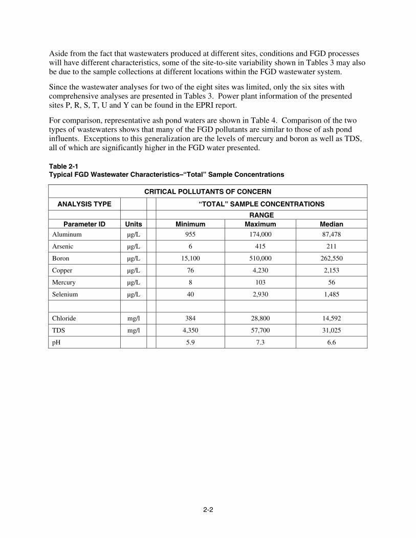
Aside from the fact that wastewaters produced at different sites, conditions and FGD processes will have different characteristics, some of the site-to-site variability shown in Tables 3 may also be due to the sample collections at different locations within the FGD wastewater system.
Since the wastewater analyses for two of the eight sites was limited, only the six sites with comprehensive analyses are presented in Tables 3. Power plant information of the presented sites P, R, S, T, U and Y can be found in the EPRI report.
For comparison, representative ash pond waters are shown in Table 4. Comparison of the two types of wastewaters shows that many of the FGD pollutants are similar to those of ash pond influents. Exceptions to this generalization are the levels of mercury and boron as well as TDS, all of which are significantly higher in the FGD water presented.
Table 2-1 Typical FGD Wastewater Characteristics–“Total” Sample Concentrations
CRITICAL POLLUTANTS OF CONCERN
ANALYSIS TYPE “TOTAL” SAMPLE CONCENTRATIONS
RANGE Parameter ID Units Minimum Maximum Median
Aluminum µg/L 955 174,000 87,478
Arsenic µg/L 6 415 211
Boron µg/L 15,100 510,000 262,550
Copper µg/L 76 4,230 2,153
Mercury µg/L 8 103 56
Selenium µg/L 40 2,930 1,485
Chloride mg/l 384 28,800 14,592
TDS mg/l 4,350 57,700 31,025
pH 5.9 7.3 6.6

2-3
Table 2-2 Typical FGD Wastewater Characteristics–“Settled” Sample Concentrations
CRITICAL POLLUTANTS OF CONCERN
ANALYSIS TYPE “SETTLED” SAMPLE CONCENTRATIONS
MAX RANGE Parameter ID Units Minimum Maximum Median
Aluminum µg/L 739 26,300 13,520
Arsenic µg/L 6 30 18
Boron µg/L 14,400 407,000 210,700
Copper µg/L 69 2980 1,525
Mercury µg/L 1.2 9.5 5
Selenium µg/L 40 1,860 950
Chloride mg/l 589 29,200 14,895
TDS mg/l 4,370 48,100 26,235
pH 5.8 7.2 6.5
Table 2-3 Typical FGD Wastewater Characteristics
CRITICAL POLLUTANTS OF CONCERN
ANALYSIS TYPE “FILTERED” SAMPLE CONCENTRATIONS
RANGE
Parameter ID Units Minimum Maximum Median
Aluminum µg/L 200 25,100 12,650
Arsenic µg/L 6.8 150 78
Boron µg/L 14,300 510,000 262,150
Copper µg/L 47 321 184
Mercury µg/L 0.1 9 5
Selenium µg/L 40 1,810 925
Chloride mg/l 584 29,200 14,892
TDS mg/l 4,360 50,500 27,430
pH 6.0 7.3 6.7

2-4
Table 2-4 Effects of Sample Settling and Filtration–Site P
CHARACTERISTICS OF FGD BLOWDOWN AT EIGHT COAL POWER PLANTS 1)
SITE P
Parameter ID Units Filtered Settled Total
Settled÷
Total
Filtered ÷
Total
COMMENTS Effects of Settling
and Filtration
Aluminum μg/L 1,000 1,000 26,000 3.8% 3.8% Significant settling and filtration
Arsenic μg/L 30 30 300 10.0% 10.0% Significant settling and filtration
Boron μg/L 255,000 261,000 244,000 107.0% 104.5% No effect
Copper μg/L 100 100 1000 10.0% 10.0% Significant settling and filtration
Mercury μg/L 0.55 2.3 73.6 3.1% 0.7% Significant settling & more by filtration
Selenium μg/L 1,610 1,660 2,930 56.7% 54.9% Moderate settling and filtration
Chloride mg/L 29,200 29,200 28,800 101.4% 101.4% No effect
TDS mg/L 48,400 48,100 57,700 83.4% 83.9% Minor effect on overall concentration
TSS mg/L 8 91 94,900 0.1% 0.0% Significant settling and filtration
pH pH units 6.7 6.7 6.7

2-5
Table 2-5 Effects of Sample Settling and Filtration–Site R
CHARACTERISTICS OF FGD BLOWDOWN AT EIGHT COAL POWER PLANTS 1)
SITE R
Parameter ID Units Filtered Settled Total
Settled÷
Total
Filtered ÷
Total
COMMENTS Effects of Settling
and Filtration
Aluminum µg/L 1,000 1,000 102,000 1.0% 1.0% Significant settling and
filtration
Arsenic µg/L 30 30 300 10.0% 10.0% Significant settling and
filtration
Boron µg/L 411,000 407,000 340,000 119.7% 120.9% No effect
Copper µg/L 321 298 4230 7.0% 7.6% Significant settling and
filtration
Mercury µg/L 7.4 6.4 91.6 7.0% 8.1% Significant settling and
by filtration
Selenium µg/L 1,810 1,860 2,000 93.0% 90.5% Minor settling and
filtration
Chloride mg/L 982 963 979 98.4% 100.3% No effect
TDS mg/L 12,600 12,800 14,200 90.1% 88.7% Minor effect on overall
concentration
TSS mg/L 2 2 170,000 0.0% 0.0% Significant settling and
filtration
pH pH
units 7.3 7.2 7.1

2-6
Table 2-6 Effects of Sample Settling and Filtration–Site S
CHARACTERISTICS OF FGD BLOWDOWN AT EIGHT COAL POWER PLANTS 1)
SITE S
Parameter ID Units Filtered Settled Total
Settled÷
Total
Filtered ÷
Total
COMMENTS Effects of Settling
and Filtration
Aluminum µg/L 200 1,990 174,000 1.1% 0.1% Significant settling and more by filtration
Arsenic µg/L 10 10 240 4.2% 4.2% Significant settling and filtration
Boron µg/L 88,300 87,900 85,200 103.2% 103.6% No effect
Copper µg/L 47.4 68.6 1530 4.5% 3.1% Significant settling and filtration
Mercury µg/L 0.1 1.2 103 1.2% 0.1% Significant settling and more by filtration
Selenium µg/L 485 508 2,000 25.4% 24.3% Moderate settling and filtration
Chloride mg/L 1,120 1,150 1,180 97.5% 94.9% No effect
TDS mg/L N/A 8,170 9,770 83.6% N/A Minor effect on overall concentration
TSS mg/L N/A 24 87,600 0.0% N/A Significant settling and filtration
pH pH units 7.3 7.1 7.1

2-7
Table 2-7 Effects of Sample Settling and Filtration–Site T
CHARACTERISTICS OF FGD BLOWDOWN AT EIGHT COAL POWER PLANTS 1)
SITE T
Parameter ID Units Filtered Settled Total Settled
÷ Total
Filtered ÷
Total
COMMENTS Effects of Settling
and Filtration
Aluminum µg/L 1,000 1,810 170,000 1.1% 0.6% Significant settling
and filtration
Arsenic µg/L 10 10 415 2.4% 2.4% Significant settling
and filtration
Boron µg/L 360,000 359,000 344,000 104.4% 104.7% No effect
Copper µg/L 100 121 1000 12.1% 10.0% Significant settling
and filtration
Mercury µg/L 0.44 1.4 78 1.8% 0.6% Significant settling
and more by filtration
Selenium µg/L 1,150 1,160 2,000 58.0% 57.5% Moderate settling and
filtration
Chloride mg/L 3,850 3,750 3,650 102.7% 105.5% No effect
TDS mg/L N/A 16,400 155 N/A N/A No data
TSS mg/L N/A 231 13,700 1.7% N/A Significant settling
pH pH 7.2 7.2 7.2

2-8
Table 2-8 Effects of Sample Settling and Filtration–Site U
CHARACTERISTICS OF FGD BLOWDOWN AT EIGHT COAL POWER PLANTS 1)
SITE U
Parameter ID Units Filtered Settled Total
Settled÷
Total
Filtered ÷
Total
COMMENTS Effects of Settling
and Filtration
Aluminum μg/L 403 739 955 77.4% 42.2% No significant
settling but moderate by filtration
Arsenic μg/L 15.5 16.3 17.3 94.2% 89.6% No significant settling and filtration
Boron μg/L 14,900 14,400 15,100 95.4% 98.7% No effect
Copper μg/L 136 157 152 103.3% 89.5% No significant settling and filtration
Mercury μg/L 3.3 7.1 7.5 94.7% 44.0% No significant
settling but moderate by filtration
Selenium μg/L 40 40 40 100.0% 100.0% No effect
Chloride mg/L 3,610 3,650 3,610 101.1% 100.0% No effect
TDS mg/L 14,300 14,400 14,600 98.6% 97.9% No effect
TSS mg/L 3 18 32 56.3% 10.3% Moderate settling but significant filtration
pH pH units 7.3 7.2 7.3

2-9
Table 2-9 Effects of Sample Settling and Filtration–Site Y
CHARACTERISTICS OF FGD BLOWDOWN AT EIGHT COAL POWER PLANTS 1)
SITE Y
Parameter ID Units Filtered Settled Total
Settled÷
Total
Filtered ÷
Total
COMMENTS Effects of Settling
and Filtration
Aluminum µg/L 25,100 26,300 26,500 99.2% 94.7% No significant settling and filtration
Arsenic µg/L 1.6 5.8 6.1 95.1% 26.2% No significant settling but moderate filtration
Boron µg/L 14,300 17,100 17,500 97.7% 81.7% No effect
Copper µg/L 145 158 157 100.6% 92.4% No effect
Mercury µg/L 9 9.5 9.5 100.0% 94.7% No effect
Selenium µg/L 131 157 172 91.3% 76.2% No significant settling but minor filtration
Chloride mg/L 584 589 592 99.5% 98.6% No effect
TDS mg/L 4,360 4,370 4,350 100.5% 100.2% No effect
TSS mg/L 5 29 35 82.9% 14.3% No significant settling, but significant filtration
pH pH units 6 5.8 5.9
1) This data represents the values for the eight individual FGD sites from the EPRI Report 1010162. Only six of the sites
are shown in Tables 2-4 through 2-9.
2-10
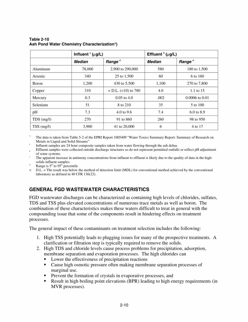
Table 2-10 Ash Pond Water Chemistry Characterization*)
Influent a (μg/L) Effluent b (μg/L)
Median Range d Median Range d
Aluminum 78,000 2,900 to 290,000 580 180 to 1,500
Arsenic 340 25 to 1,500 60 6 to 160
Boron 1,200 430 to 5,500 1,100 270 to 7,800
Copper 310 < D.L. (<10) to 780 4.0 1.1 to 15
Mercury 0.3 0.05 to 4.0 .002 0.0006 to 0.01
Selenium 51 8 to 210 35 5 to 100
pH 7.3 4.0 to 9.6 7.4 6.0 to 8.9
TDS (mg/l) 270 91 to 860 260 98 to 950
TSS (mg/l) 3,900 41 to 20,000 6 4 to 17
*) The data is taken from Table 5-2 of the EPRI Report 1005409 “Water Toxics Summary Report: Summary of Research on
Metals in Liquid and Solid Streams” a Influent samples are 24 hour composite samples taken from water flowing through the ash deltas b Effluent samples were collected outside discharge structures so do not represent permitted outfalls or reflect pH adjustment
of some systems. c The apparent increase in antimony concentrations from influent to effluent is likely due to the quality of data in the high-
solids influent samples. d Range is 5th to 95th percentile < D.L. = The result was below the method of detection limit (MDL) for conventional method achieved by the conventional
laboratory as defined in 40 CFR 136(22).
GENERAL FGD WASTEWATER CHARACTERISTICS
FGD wastewater discharges can be characterized as containing high levels of chlorides, sulfates, TDS and TSS plus elevated concentrations of numerous trace metals as well as boron. The combination of these characteristics makes these waters difficult to treat in general with the compounding issue that some of the components result in hindering effects on treatment processes.
The general impact of these contaminants on treatment selection includes the following:
1. High TSS potentially leads to plugging issues for many of the prospective treatments. A clarification or filtration step is typically required to remove the solids.
2. High TDS and chloride levels cause process problems for precipitation, adsorption, membrane separation and evaporation processes. The high chlorides can Lower the effectiveness of precipitation reactions Cause high osmotic pressure often making membrane separation processes of
marginal use. Prevent the formation of crystals in evaporative processes, and Result in high boiling point elevations (BPR) leading to high energy requirements (in
MVR processes).

2-11
3. High calcium can lead to scaling and cause process interferences in adsorption, membrane separations and evaporation processes.
4. The presence of selenium in its selenate form essentially limits the treatment option for this component to biological remediation or requires a chemical reduction procedure as pretreatment.
5. Arsenic in the form of arsenite may have to be oxidized to make it more amenable to chemical or adsorptive removal.
6. The presence of boron requires special treatment considerations. Boron is a difficult substance to remediate by conventional treatment methods. Removal is highly pH dependent.
7. The presence of nitrates may interfere with biological treatment, requiring additional treatment steps.
8. The ever more stringent regulatory requirements being promulgated have resulted in fewer treatment options capable of reaching the extremely low limits often required.
9. Sulfates, which are typically present at relatively high levels, can cause interferences with several of the treatment processes, either by producing saturated or supersaturated calcium sulfate solutions or by competing with some of the reactions, especially for the treatment of selenate. (Sulfur and selenium are neighbors with the same column in the periodic table and, as such, have many of the same properties, leading to competing reactions.)

3-1
3 POLLUTANTS OF CONCERN
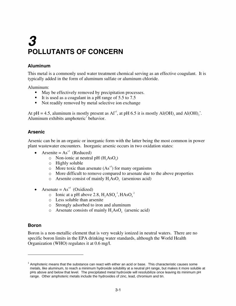
Aluminum
This metal is a commonly used water treatment chemical serving as an effective coagulant. It is typically added in the form of aluminum sulfate or aluminum chloride.
Aluminum: May be effectively removed by precipitation processes. It is used as a coagulant in a pH range of 5.5 to 7.5 Not readily removed by metal selective ion exchange
At pH = 4.5, aluminum is mostly present as Al+3, at pH 6.5 it is mostly Al(OH)3 and Al(OH)2
+. Aluminum exhibits amphoteric1 behavior.
Arsenic
Arsenic can be in an organic or inorganic form with the latter being the most common in power plant wastewater encounters. Inorganic arsenic occurs in two oxidation states:
• Arsenite = As+3 (Reduced) o Non-ionic at neutral pH (H3AsO4) o Highly soluble o More toxic than arsenate (As+5) for many organisms o More difficult to remove compared to arsenate due to the above properties o Arsenite consist of mainly H3AsO3 (arsenious acid)
• Arsenate = As+5 (Oxidized)
o Ionic at a pH above 2.8, H2ASO4
-1, HAsO4
-2 o Less soluble than arsenite o Strongly adsorbed to iron and aluminum o Arsenate consists of mainly H3AsO4 (arsenic acid)
Boron
Boron is a non-metallic element that is very weakly ionized in neutral waters. There are no specific boron limits in the EPA drinking water standards, although the World Health Organization (WHO) regulates it at 0.6 mg/l.
1 Amphoteric means that the substance can react with either an acid or base. This characteristic causes some
metals, like aluminum, to reach a minimum hydroxide solubility at a neutral pH range, but makes it more soluble at pHs above and below that level. The precipitated metal hydroxide will resolubilize once leaving its minimum pH range. Other amphoteric metals include the hydroxides of zinc, lead, chromium and tin.

3-2
Boron in water is always present as some form of boric acid, which is a very weak acid. At a pH lower than 7, boric acid is undissociated as H3BO3 or B(OH)3. At a pH higher than 11.5, boron occurs as borate [B(OH)4]
—.
Removal of boron requires treatment at elevated pHs where the substance becomes more ionized, which is a prerequisite for many treatment processes.
Copper
Copper, a heavy metal element, is not normally present in FGD wastes at high levels. If it does exist, it is primarily in the fully oxidized cupric Cu+2 state. In this state it is easily taken up by cation ion exchange resins and similar natural substances such as zeolites and clinoptilolites. Human health risks from this metal at low levels are minimal.
Copper removal techniques have been extensively developed for the plating industry. These primarily revolve around either ion exchange or precipitation as the reduced or chelated metal. Treatment with sulfides (sodium sulfide or thiosulfates) has been effective in removing copper to low levels.
Mercury
Mercury General Description
Mercury is one of the most strictly regulated elements on the pollutant list, often restricted to less than 1 ppb or less.
Mercury is a ubiquitous pollutant typically found in FGD scrubber wastewaters.
Mercury is amenable to reduction to very low levels using carbonate, phosphate or sulfide precipitation techniques. The use of organo-sulfides has also proven effective in obtaining very low treatment residual levels.
When mercury is precipitated as the sulfide, high mercury residuals are often observed. This is due to the reduction of the mercury to its metallic state by the sulfides present. Once in the metallic form, the mercury no longer precipitates as an insoluble sulfide. Metallic mercury is soluble in water at about 25 µg/l, which is above the regulatory limits. The residual mercury in the treated water must, therefore, be oxidized to Hg+2 and then retreated to achieve low residual concentrations.
Mercury can also be removed by ion exchange using either a chelating resin or a mercury specific resin.
Mercury can be reduced to low concentrations by a reducing agent. Granulated carbon is often used to polish treated mercury solutions, but with varying success. A multi-step process is typically required to reduce mercury concentrations to very low levels.

3-3
Selenium
Selenium General Description
Selenium is a metalloid element that is located just below sulfur in the periodic table. It resembles sulfur and forms many of the same compounds. The solubilities of selenium are similar to sulfur salts. Most selenate salts are more soluble than selenite salts.
Selenium can be in as many as five different oxidation states. Some are anions, some are neutral and some are cations with the most common forms being:
• Selenate Se+6 SeO4
-2 • Selenite Se+4 HSeO3
-1 • Selenium (elemental) Se0 Se • Selenide Se-2 HSe-1
Selenate and selenite are the most common species in aqueous solutions. Selenium combines with oxygen to form several other selenium compounds as well. In oxygenated environments, selenium is typically present in the selenate form, while selenite should be the predominant specie in reducing conditions.
Selenite is more amenable for removal by conventional precipitation technologies than selenate. Selenate, which is the less toxic of the two forms, is the specie likely present in FGD wastewaters, especially for forced oxidation designs. Selenite may be predominant for inhibited or natural oxidation FGDs. However, EPRI has at this time only limited data (5 data sets). Additional data will be required to further allow definition of this aspect.
A complicating factor in identifying selenate vs. selenite presence is that there is some uncertainty about the analytical methods to speciate selenium. EPRI is presently initiating a study to compare the various sampling/analytical approaches. Some researchers have theorized that other forms of selenium (including organic forms) may be present in FGD wastewater. This hypothesis is also being evaluated, and especially for FGDs that add an organic acid such as dibasic acid (DBA). For additional information, see - http://www.appliedspeciation.com/Selenium_in_FGD_Wastewater.htm


4-1
4 WASTEWATER TREATMENT TECHNOLOGIES
General Concepts
There are several approaches to dealing with FGD wastewaters. As in all processing options, there are advantages and disadvantages to each. In finding the best suited design for a particular FGD wastewater treatment application many factors have to be weighed in order to find the most suitable option.
Specific factors affecting the selection for the best treatment options include:
Type of FGD system used (reagent type, oxidation approach, recycle ratio/metallurgy) Overall plant water management concept FGD wastewater blending with other plant wastewaters Plant design (e.g. air pollution control) Other plant treatment processes already installed, potential integration of processes NPDES requirements Costs
The following is a general discussion of the treatment systems available. More detailed discussions of various treatment technologies can be found later in this document.
Chemical Treatment Processes
Chemical treatment processes in the form of hydroxide precipitation using lime or sodium hydroxide are used to precipitate mainly calcium and magnesium from the wastewater along with some of the heavy metal pollutants. The softened water is then returned to the FGD process. This operation also removes some trace metal pollutants, but typically not to the levels required for discharge.
In order to meet the strict discharge limits for metals, additional chemical treatment in the form for iron coprecipitation or, more effectively, via organo- or inorganic sulfide precipitation can be employed.
Iron coprecipitation, and especially in conjunction of sulfide precipitation processes, is capable of achieving very low levels of metal residuals, removing them to low ppb levels. The organo sulfide reagents TMT 15® (described later in this document) has shown great success in this application. Organo, as well as inorganic sulfide precipitation, which are established but infrequently used technologies, work well to reduce heavy metals to essentially the lowest levels that technology presently has to offer for FGD waters. Sulfide sludges typically bind the heavy metals in a very stable formation. Depending on the facility design, the sludge may be disposed of separately or it may be commingled with the hydroxide sludges from upstream or other treatments.

4-2
Nalco Company, a world wide supplier of water treatment chemicals, has supported FGD water treatment efforts by supplying flocculation aids and other chemicals to improve precipitation, settling and thickening performances. Nalco’s Nalmet® products were developed specifically for the remediation of heavy metals. The specific reagent Nalmet® 1689 has been used for the removal of such pollutants, including selenium and mercury. While the reagent differs from TMT, this proprietary material does contain sulfur. According to the manufacturer, Nalmet® 1689 has a high tolerance for variable wastewater characteristics, low aquatic toxicity and results in a 75-80% reduction in flocculent usage plus a 20 to 80% reduction in sludge volume compared to conventional additives.
Biological Treatment Systems
Biological treatment systems typically consist of aerobic or anaerobic processes that use pollutant specific bacteria to attack individual pollutants. The remediation of arsenic and selenium, for example, requires a two stage biological reactor. Arsenic is targeted with one type of bacterium in the first chamber and is then followed by a second reaction chamber containing a selenium specific bacterium. Additional pollutants may require further reaction chambers in series.
Selenate, the selenium form most commonly found in forced oxidation FGD wastewaters and the specie that is more difficult to treat using chemical processes, is found be readily remediated using anaerobic biological reactors as is selenite.
Passive treatment systems, commonly called constructed wetlands (CWTS), use a combination of biological and physical adsorption processes to remediate different pollutants. This technology has found acceptance in the power industry since it is a relatively inexpensive and has the significant advantage of being low maintenance, a minimal consumer of power and other consumables, and presenting a visually pleasing treatment option that can be beneficial for a plant’s public image. However, pilot tests evaluating a slipstream of FGD wastewater (as described in Section 5.4) were not effective for treating some metals including selenate. Furthermore, other components such as boron, adversely impacted operation.
While effective in remediating wastewaters in general, the CWTS influents may have to be subjected to pretreatment steps in the form of settling and/or oxidation basins to make the passive wetlands processes more effective.
Comprehensive Treatment
Overview
Depending on the FGD wastewater characteristics and process requirements, it may be necessary or advantageous to treat the wastewater stream for all the pollutants, returning a relatively pure, desalinated water stream to the FGD or other power plant uses.
This approach, which is typically the most costly, usually employs some form of evaporative processes. While membrane separation methods may be considered, the high salinity and nature of the FGD waters often places this option beyond the capabilities of such treatment.

4-3
In order to subject the whole FGD stream to evaporative or possibly membrane treatment, the wastewater may have to undergo several pretreatment steps to make it suitable for processing.
Depending on the feed water characteristics and stream flow rate, the evaporation option may consist of one of, or the combination of, a brine concentrator, crystallizer, spray dryer and evaporation pond.
Technical Challenges
Modified desalination technologies in the form of membrane separations and evaporation processes have been successfully applied to power plant wastewaters for over 30 years, treating a variety of discharges, including cooling tower blowdown, ash pond waters and at times FGD discharges that are often blended with other power plant wastewater streams.
The challenge of applying either of these techniques to FGD operations is that these waters are saturated or supersaturated with calcium sulfate, are high in chlorides and contain components that can cause process interferences.
Evaporation
Evaporation is a comprehensive means of dealing with FGD wastewaters, resulting in the capture of essentially all of the water’s pollutants and returning clean water to the process or other plant uses. One downside of this approach is that with evaporation, even with mechanical or thermal vapor recompression (MVR or TVR) or other energy saving processes, the overall energy consumption is significantly higher as compared to the other technologies discussed.
The evaporative systems that have been successfully used for treating power plant wastes for over 30 years are vapor compression, falling film evaporators, commonly referred to as brine concentrators (BC). They have been the workhorse for dealing with cooling tower blowdown and other power plant wastewaters, especially in southwestern plant locations.
Due to the more concentrated nature of FGD blowdown streams plus the presence of trace metals and other pollutants in relatively high concentrations, common evaporation systems and processes will have to be modified to accommodate the characteristics of the FGD waters.
The general approach to dealing with the FGD may consist of one of the following treatment train scenarios:
1. Brine concentrator or crystallizer with discharge to an evaporation pond 2. Brine concentrator followed by a crystallizer and/or a spray dryer 3. Brine concentrator followed by a spray dryer 4. Evaporator/crystallizer followed by a spray dryer or evaporation pond 5. Solar evaporation pond only.
Selection of the best option will be dependent on the FGD wastewater characteristics and plant requirements as well as the plant specific waste disposal options.

4-4
There are numerous brine concentrators treating cooling tower blowdown with or without additional mixed power plants wastes. A few evaporation processes are also operating on coal gasification wastewaters. Although there are no such systems operating on strictly FGD wastewaters at this time, there are evaporative systems treating similar power plant wastewaters and there are several strictly FGD wastewater evaporator systems presently in the design phase or under construction. (A partial list of these systems can be found later in this document,)
Reverse Osmosis
Reverse Osmosis (RO) has proven to be a cost effective means of achieving wastewater volume reduction, often as the initial treatment for the large cooling tower blowdown streams. Recent innovations, like the high efficiency reverse osmosis HERO™ process (described in later sections of this document), have added to the usefulness of this technology by allowing operation at high silica levels.
Application of reverse osmosis membranes has some significant limitations:
1. The feed water must be low in turbidity and void of TSS. 2. The saturation level of any of the chemical constituents may not be significantly
exceeded. 3. The osmotic pressure cannot exceed the membrane pressure capability.
Feed clarity or turbidity can typically be satisfied by proper prefiltration using conventional or micro- or ultra-filtration. Feed saturation, usually addressed by chemical or adsorptive softening, is more of a challenge with FGD wastewaters since the calcium saturation levels can be quite high. This problem can, however, often be mitigated with the proper treatment design.
The biggest limitation for membranes treating strictly FGD wastewaters is the osmotic pressure resulting from the high chloride content. Since there is no cost effective means of resolving this issue, membrane systems may be of only limited or marginal use for high TDS FGD wastewaters. If the feed salinity is such that a reasonable recovery factor can be achieved, then the membrane process can, however, be considered.
A recently issued specification for a FGD wastewater treatment system at Kansas City Power and Light listed either evaporation or reverse osmosis (using the HERO™ process) as the two process options (see details below).
While reverse osmosis and the HEROTM processes have been successfully used in power plant ZLD applications, to date there are no membrane processes operating on strictly FGD waters.
Individual Treatment Processes
Treatment processes that target specific or a small group of components include:
1. Bauxsol products - Virotec Global Solutions Pty Ltd 2. Selective ion exchange (for heavy metals, specific metals or boron) 3. Adsorption media like granular iron or other metal oxide or hydroxide
Granular ferric oxide (GFHTM) – Siemens/US Filter Granular ferric hydroxide (GFO) – Severn Trent Water Purification, Inc. Granular titanium oxide (GTO) – Dow

4-5
Although the above media processes have been shown to be effective for the removal of arsenic, selenium and other pollutants in drinking water as well as in acid mine drainage remediation, they have not been used in power plant applications. With the possible exception of the Virotec products, the more concentrated pollutant levels of FGD waters may limit these adsorptive media to polishing operations.
The above iron based media are described in detail in “Arsenic & Selenium Treatment Technology Summary For Power Plant Wastewaters”, EPRI Report # 1005365, published in November 2004.


5-1
5 FGD TREATMENT OPTIONS–RECENT DEVELOPMENTS The following potential treatment options for FGD wastewaters focus on the remediation of the pollutants of concern. As previously noted, there is no single process that can accomplish this task with a single, stand-alone tactic.
In devising treatment schemes for the remediation of specific wastewater pollutants from FGD wastewaters with proven technologies, the following approaches have been taken by system designers and suppliers.
Treatment for Specific Pollutants
Trace Metals
The following outlines potential approaches for the treatment of arsenic, copper, mercury and selenite.
1. Conventional hydroxide precipitation using sodium hydroxide or lime:
Removal efficiencies are to the low ppm range. Capacity to reduce pollutants to moderate residual levels of metals, including arsenic
(arsenate), copper and mercury Also effective for other metals Due to the amphoteric nature of some metals, treatment compromises have to be
made, which prevent achieving the minimum solubilities for individual metals Hydroxide precipitation typically does not achieve the low residual levels required for
wastewater discharge 2. Iron coprecipitation:
Removal efficiencies are higher than with hydroxide methods, typically to low ppm or high ppb ranges
Effective for the removal of heavy metals, including arsenic, copper and mercury as well as removal of selenite (but not selenate)
Also effective for other metals
3. Organo or inorganic sulfide coprecipitation:
Removal efficiencies to a ppb range, with some species to below 1 ppb level The solubilities of metal sulfides are typically 100 to 1000 (or more) times lower
compared to metal hydroxides Effective for the removal of heavy metals, including arsenic, copper and mercury Also effective for other metals including chromium (including Cr+6), vanadium and
antimony Metal sulfide precipitates do not exhibit amphoteric behavior
5-2
The most common organo-sulfide used is the Degussa product TMT 15® (see detailed discussion later in this document). Other products are available as well.
The inorganic reagent typically used is sodium sulfide Metal sulfide sludges are stable
Treatment Approaches
Numerous bench and pilot studies have been conducted in an attempt to establish viable treatment approaches to dealing with FGD wastewaters. While there have been some treatment systems installed, reducing the pollutants of concern to the ppb level is a relatively new requirement so that there is only limited experience for the design and operation of the potential remediation treatment technologies available.
FGD Treatment Experience
The following describes a number of demonstration tests conducted by the power plant industry.
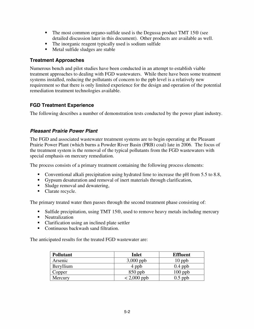
Pleasant Prairie Power Plant
The FGD and associated wastewater treatment systems are to begin operating at the Pleasant Prairie Power Plant (which burns a Powder River Basin (PRB) coal) late in 2006. The focus of the treatment system is the removal of the typical pollutants from the FGD wastewaters with special emphasis on mercury remediation.
The process consists of a primary treatment containing the following process elements:
Conventional alkali precipitation using hydrated lime to increase the pH from 5.5 to 8.8, Gypsum desaturation and removal of inert materials through clarification, Sludge removal and dewatering, Clarate recycle.
The primary treated water then passes through the second treatment phase consisting of:
Sulfide precipitation, using TMT 15®, used to remove heavy metals including mercury Neutralization Clarification using an inclined plate settler Continuous backwash sand filtration.
The anticipated results for the treated FGD wastewater are:
Pollutant Inlet Effluent Arsenic 3,000 ppb 10 ppb Beryllium 4 ppb 0.4 ppb Copper 850 ppb 100 ppb Mercury < 2,000 ppb 0.5 ppb

5-3
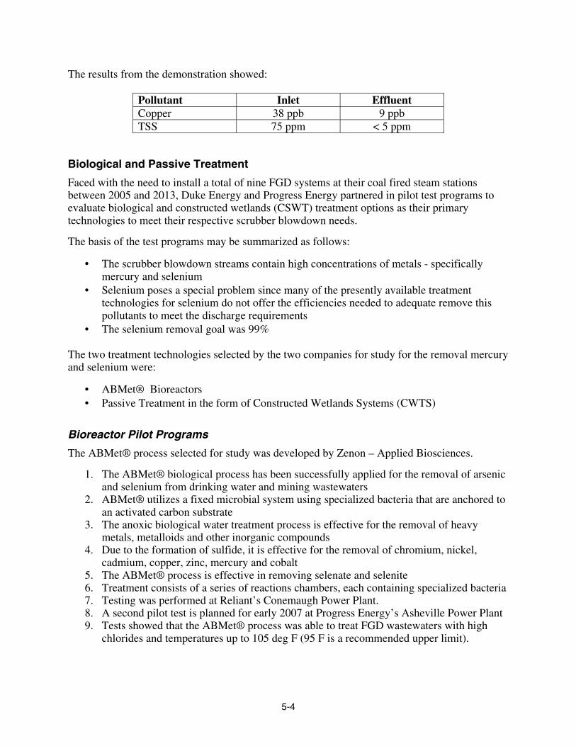
Clinch River
A one-year study was performed testing both organic and inorganic treatments at the American Electric Power’s Clinch River Station, located near Cleveland, Virginia
The feed water consisted of a combination of ash pond wastewater, cooling tower blowdown and miscellaneous plant discharges. The goal was to reduce copper and TSS to the level required by the NPDES permit.
1. The treatment approach consisted of:
Iron co-precipitation Supplemental feed with sulfide Polymer addition
2. The system had two 2,700 gpm trains with the following process equipment: Degremont Accelerator Solids Contactor Degremont Greenleaf Filter
3. The process used a rapid mix tank for ferrous sulfate and sodium hydroxide reactions 4. Operation was at a pH of 8.5 5. After chemical addition and pH adjustment the water entered an aeration tank 6. Sulfide was added before entering the 65 ft diameter clarifier 7. Solids were removed in a single 40 ft diameter Greenleaf filter.
5-4
The results from the demonstration showed:
Pollutant Inlet Effluent Copper 38 ppb 9 ppb TSS 75 ppm < 5 ppm
Biological and Passive Treatment
Faced with the need to install a total of nine FGD systems at their coal fired steam stations between 2005 and 2013, Duke Energy and Progress Energy partnered in pilot test programs to evaluate biological and constructed wetlands (CSWT) treatment options as their primary technologies to meet their respective scrubber blowdown needs.
The basis of the test programs may be summarized as follows:
• The scrubber blowdown streams contain high concentrations of metals - specifically mercury and selenium
• Selenium poses a special problem since many of the presently available treatment technologies for selenium do not offer the efficiencies needed to adequate remove this pollutants to meet the discharge requirements
• The selenium removal goal was 99%
The two treatment technologies selected by the two companies for study for the removal mercury and selenium were:
• ABMet® Bioreactors • Passive Treatment in the form of Constructed Wetlands Systems (CWTS)
Bioreactor Pilot Programs
The ABMet® process selected for study was developed by Zenon – Applied Biosciences.
1. The ABMet® biological process has been successfully applied for the removal of arsenic and selenium from drinking water and mining wastewaters
2. ABMet® utilizes a fixed microbial system using specialized bacteria that are anchored to an activated carbon substrate
3. The anoxic biological water treatment process is effective for the removal of heavy metals, metalloids and other inorganic compounds
4. Due to the formation of sulfide, it is effective for the removal of chromium, nickel, cadmium, copper, zinc, mercury and cobalt
5. The ABMet® process is effective in removing selenate and selenite 6. Treatment consists of a series of reactions chambers, each containing specialized bacteria 7. Testing was performed at Reliant’s Conemaugh Power Plant. 8. A second pilot test is planned for early 2007 at Progress Energy’s Asheville Power Plant 9. Tests showed that the ABMet® process was able to treat FGD wastewaters with high
chlorides and temperatures up to 105 deg F (95 F is a recommended upper limit).

5-5
The ABMet® process showed the following removal efficiencies:
Pollutant Removal Efficiency
Selenium 98 – 99% Mercury ~ 95% Arsenic ~ 96% Cobalt, Copper, Lead, molybdenum and Zinc
> 90%
Passive Treatment System (Constructed Wetlands)
The constructed wetlands tests of the Duke Energy and Progressive Energy program were conducted at Duke’s Marshall Steam Station by Clemson University.
The specific process parameters of the Marshall Steam Station CWTS pilot study were:
• Parameters entering the CWTS: – Temperature < 105F – Chloride < 4,000 ppm – TSS < 1,000 ppm – Selenium 2,000 ppb – Mercury < 15 ppb – Boron < 50 ppm – BOD < 50 ppm
The remediation results of the program for the targeted pollutants were as follows:
Pollutant CWTS Influent CWTS Effluent Selenium 2,000 ppb < 200 ppb Mercury < 15 ppb < 0.5 ppb
The passive treatment approach did not achieve the desired selenate removal. It is postulated that the relatively low levels of nitrogen and phosphorous had a detrimental effect on the wetland’s effectiveness. Further development will be required to identify the influence of such deficiencies. Some of the difficulties encountered were the relatively high boron level (about 50 ppm), which was suspected of killing the plants. It was further conjectured that the dibasic acids (DBA) were negatively affecting the BOD reduction. The wetlands were able to achieve 70% Hg removal.
(The issue with DBA is chemical oxygen demand (COD). DBA biodegrades readily in the presence of inoculum bacteria and appropriate nutrients in the environment of the conditioned wastewater. DBA is typically dosed at about 1,000 ppm in the scrubber, and some DBA is present in the FGD wastewater. (Approximately 70% of the DBA in the wastewater is used by the bacteria for respiration and the remainder for cell growth. The 30% DBA may, therefore, have to be periodically removed as sludge.)
5-6
TREATMENT SELECTION
Based on the pilot test work conducted to date, Duke Energy and Progress Energy each decided to implement a mix of treatment techniques consisting of the following treatment stages:
Primary: Solids removal and clarification pretreatment in the form of a filter, clarifier or settling pond.
Second: Mercury reduction and/or biological selenium reduction using bioreactors Third: Constructed wetlands
All treatment options included a form of the primary stage, followed by either a secondary and/or tertiary stage, or a combination of the two.
Other Passive Treatment System Demonstration Programs
Several demonstration projects for passive treatment systems have been conducted to evaluate and demonstrate the viability of using this remediation approach for power plants wastewaters. Only a few of these involved FGD wastewaters:
TVA PARADISE
EPRI was involved with TVA in a passive treatment system demonstration project at TVA’s Paradise Fossil Plant, located in Muhlenberg County, KY for the remediation of FGD and ash pond wastewaters. Contaminates of interest are ammonia, arsenic, selenium and mercury.
The 125,000 gpd demonstration project consisted of two treatment processes involving constructed wetlands, one using a conventional and the second an enhanced pretreatment approach. Both demonstrations were performed in parallel.
The two treatment concepts consisted of the following:
Treatment 1: Trickling Filter Constructed Wetlands
Treatment 2:
Trickling Filter ZVI Extraction Trench Settling/Oxidation Basin Constructed Wetlands
The ZVI extraction trench consisted of a layered rock bed topped by a 6-inch layer of iron filings.

5-7
The preliminary results of the demonstration showed the following results:
Pollutant Inlet Effluent Arsenic 6.3 ppb 3.5 ppb Selenium 52 ppb 8 ppb Mercury 85.5 ppt 27.7 ppt
ADDITIONAL POWER PLANT APPLICATIONS
Although not used for FGD applications, the following plant description provide information about passive treatment systems that are presently operating on related wastewaters, specifically generated by coal pile run-off and leachates.
ALABAMA POWER COMPANY – PLANT GORGAS
Alabama Power Company’s Plant Gorgas has employed a reducing and alkalinity producing system (RAPS) based wetland for the treatment of storm water from a coal pile. Alkalinity is typically introduced by passing the influent water over a limestone bed before entering the wetlands. After treatment by the RAPS, the water is conveyed to surface flow wetlands for metals removal.
Allegheny Energy has several passive treatment systems, as describe below:
HATFIELD
This passive treatment system was constructed in 2000 for compliance treatment of coal combustion byproduct (CCB) leachate. It consists of an initial oxidation/precipitation basin for iron removal, four surface flow wetland cells for iron and aluminum polishing, and a series of manganese-oxidizing bacteria beds for manganese removal. For added manganese removal capacity, terraced bacteria beds were added at the terminal discharge point for additional manganese removal using newly established design criteria. Since placed on-line, the system treats an average flow of 175 gpm, achieving NPDES required effluent levels for aluminum, iron, manganese, thallium and TSS.
HARRISON
Completed in 2002, this system is among the largest and most complex passive treatment applications in the utility industry for CCB leachate. Covering a10-acre site, the system sequences a series of passive technologies, which phase the removal of contaminants to optimize the efficiency of downstream units for the removal of targeted trace elements.
The system is designed for up to 300 GPM of combined coal combustion byproduct leachate and abandoned coal mine drainage, with elevated aluminum, hexavalent chromium, iron, and selenium. A pair of oxidation/precipitation basins removes iron and aluminum and co-precipitate arsenic. The waters are then treated by three surface flow wetlands for residual heavy metals removal. Flows then enter two parallel vertical flow wetlands, where strongly reducing conditions eliminate hexavalent chromium and selenium. Residual selenium is removed by two additional surface flow wetlands, followed by two manganese oxidizing bacteria cells for final polishing of metals to low concentrations. Since placed in operation, the system has met stringent NPDES criteria for pH, iron, manganese, aluminum, selenium, arsenic, and hexavalent chromium.
5-8
ALBRIGHT
Constructed in 1988 this system is one of the oldest passive treatment systems in the electric utility industry. Currently, the system consists of six surface flow wetland cells with a total area of approximately ½ acre and three manganese-oxidizing bacteria beds (MOB). The system has evolved over time as new passive treatment information became available. The last construction phase to update the system was in 1996 with the installation of the MOBs. The system treats leachate from a closed coal combustion by-product landfill. Since completion of the full system it has consistently treated acidity, alkalinity, aluminum, iron, manganese, nickel, zinc and TSS to compliance levels.
SPRINGDALE
Constructed in 1995 this system treats leachate from a closed coal combustion by-product landfill. The system consists of a pond to oxidize iron, four surface flow wetlands, two manganese-oxidizing bacteria beds, organic up-flow cell (reducing cell) and an algal basin. The system achieves NPDES compliance for all metals (e.g., iron, manganese and aluminum) but not boron
MARSHALL STEAM STATION – Duke Energy
This facility has a 12.5 acre wetlands designed to remove mercury and selenium from scrubber blowdown. This 125 mgd passive treatment system is used as a polishing step before discharge. This wetland will come on-line in 2007, along with the new FGD system.
Bioreactor (ABMet®) vs. Passive Treatment Systems
A comparison of the ABMet® process with Passive Treatment (constructed wetlands) remediation can be summarized as follows:
1. Both technologies require: Pretreatment to remove suspended solids Treatment temperatures must be below 105 F
2. The ABMet® advantages over Passive Treatment Systems include: Tolerance of high chloride levels in the wastewater The process equipment is much smaller in physical size It has shown higher pollutant removal efficiencies, especially for selenium (selenate)
3. Advantages of constructed wetlands over bioreactors include that they are: A passive treatment Environmentally pleasing in appearance Can accommodate flow variations Need less maintenance
6-1
6 EXISTING TREATMENT PROCESSES
Evaporation Processes
FGD wastewaters pose special challenges for the brine concentrator (BC) systems that are often employed in power plant ZLD operations. A major component of FGD waters is calcium chloride, which is often present in high concentrations. Calcium chloride has an extremely high solubility, making it very difficult to precipitate or crystallize. The application of typical seed slurry operations to prevent scaling may, therefore, not be feasible. The alternative to the seed slurry process for scale control is the softening of the feed water, typically using lime soda ash methods. If the calcium chloride can be transformed to sodium chloride by soda ash addition, then the less soluble sodium chloride can be crystallized in evaporator or crystallizer systems.
Aside from metallurgical issues, another problem resulting from the high chloride levels is the high boiling point rise (BPR) in the evaporator concentrate. While not as significant for steam driven evaporation, the use of the more energy efficient vapor compression cycle may be marginal at higher brine concentrations, limiting the possible concentration factor and consequently the volume reduction achievable in a MVR system.
In addition to the high TDS and chloride levels in the FGD wastewaters, the presence of some of the pollutants may give cause to additional concern. In typical evaporation processes the pollutants carried in the feed remain in the concentrate either in a crystallized, adsorbed or soluble form. If the evaporator concentrate is dewatered or dried, the heavily concentrated pollutants are present in this residual, typically in an un-stabilized form. If crystallized or treated in a dryer, the dried materials are bagged immediately to prevent re-solubilizing of the chlorides and potentially of the other pollutants as well. (Calcium chloride salts quickly absorb enough moisture to re-solubilize a significant portion of the salts in short order, unless tightly bagged.) Disposal of this soluble material may, therefore, be costly unless it can be relegated to a mine or at another convenient, but contained site.
Boron poses another difficulty for typical evaporation processing. In seed slurry applications, boron seems to hinder the crystallization process, resulting in “sticky” solids that interfere with the preferential crystallization requirements. Due to boron’s volatility, special provisions must also be made to keep it from vaporizing and, thereby, contaminating the distillate stream.
Spray dryers can be used in place of crystallizers or even evaporators. Spray dryers are well suited for this application, requiring no or only minor pretreatment. Increased natural gas prices have, however, made their operation expensive, so that upstream volume reduction is of greater significance.
In summary, evaporation is a viable means of treating the complete FGD wastewater streams. Special considerations and accommodations must, however, be made to modify conventional evaporation and crystallizer systems to successfully and economically process such waters.
6-2
Conventional Chemical Precipitation
Lime Precipitation for Metal Hydroxides
Metals removal using lime and/or caustic utilizes similar equipment as is commonly used for lime or lime/soda softening. Lime and/or caustic precipitation for metals requires operation at specific pHs, which correspond to the minimum solubilities of the metal(s) to be removed. As previously stated, different metals find their minimum hydroxide solubility at different pHs so that the pH has to be tuned based on the metals present.
Conventional metal hydroxide precipitation typically lowers metals to the low ppm range, depending on operating pH and the presence of metal complexes. Metal removal can be enhanced using coagulation or coprecipitation with iron. In order to achieve some of the very low metals residual levels, sulfide precipitation or other polishing techniques must be used. (See following discussions.)
Enhanced Chemical Precipitation
Iron Coprecipitation
Metal co-precipitation is an effective means of treating for arsenic, aluminum, copper and selenium (Se+4, but not Se+6). Iron co-precipitation is a chemical precipitation - clarification process that uses iron salts such as ferric chloride and ferrous or ferric sulfate with pH control to precipitate heavy metals from wastewater. Studies have cited iron co-precipitation to be the most effective and practical method for arsenic removal. An associated benefit of this process is the accompanying removal of suspended solids from the water.
In conventional chemical treatment using caustic, metals are precipitated as their hydroxides. Since different metals find their lowest solubility at varying pHs, the treatment of mixed metal streams requires an operation at a compromise pH, which is typically targeted for the removal of the most critical component. (See previous discussion of the amphoteric nature of metal hydroxides.) Alternatively a multi-step precipitation process can be employed to target and minimize the residual concentrations of the different metals.
Iron co-precipitation mitigates this shortcoming as the process relies on the optimum pH for forming ferric hydroxide precipitate rather then that of the different metals. The metals are removed by adsorption onto and coprecipitation with the ferric hydroxide forming multi-metal solids “complexes”. This allows the mixed metal removal process to be carried out in a single and narrow pH range of typically 8.0 – 8.5. The iron in the added salt is removed as part of hydroxide precipitate. The anion portion of the salt stays in solution, however, adding to the TDS of the effluent.
Use of iron is more effective than using aluminum salts for coprecipitation. The iron adsorptive properties facilitate the binding of single or multiple metals present. The complexing of iron improves the effectiveness of the precipitation process and typically achieves better results than can be achieved with other precipitation and flocculation aids.
Iron coprecipitation using ferric chloride has been shown to be very effective for arsenic removal, especially arsenate (As+5). Arsenite (As+3) is typically less successfully removed and is more affected by water background composition. Arsenite may, therefore, have to be subjected

6-3
to a prior oxidation step in order to facilitate its removal to low levels. Other metals and selenite are also effectively removed. As previously stated, iron coprecipitation typically achieves metals removal down to the low ppm or high to middle ppb range, depending on the wastewater characteristics.
The sludge residual from this process may be in an unstabilized form, which may give it a hazardous waste designation.
High sulfate and silica levels may cause process interferences. Iron salts, like ferric chloride, are very corrosive, adding special design and maintenance issues to the equipment and operation. Iron sludges are typically voluminous and difficult to dewater.
Inorganic Metal Sulfide Precipitation
Chemical precipitation using sulfide salts (sodium, ferrous or calcium sulfide) can achieve significantly lower metal concentrations in the treated water, often reducing the metal residual by a factor of 100 to 1000 or more, compared to hydroxide levels. A further advantage of sulfide precipitation is that, unlike hydroxides, metal sulfides are not amphoteric, so that they do not resolubilize with changing pH. Residual metal sulfide sludge volumes are smaller compared to hydroxides. Sulfide precipitation effectively removes most metals to very low levels, including copper and mercury.
The disadvantage of using sulfide precipitation is the potential of forming hydrogen sulfide gas at low pHs and, depending on the type of sulfide salt used, the effluent may have to be oxidized to reduce the dissolved sulfide residual after precipitation.
While the sulfide process is suitable for the treatment of aluminum, copper, mercury it is only marginally effective for arsenic and selenium.
Organo Sulfite Precipitation– TMT 15®
An alternate option to inorganic sulfide precipitation is the use of TMT 15®, a product made by Degussa GmBH of Germany. This reagent, which is a 15% aqueous solution of the trimercapto-s-triazine, trisodium salt (C3N3S3Na3), was developed to achieve comparable metal removal capability to the inorganic sulfide process, but with a more benign product. TMT 15® has been extensively used in Europe for the removal of mercury from incineration stack gases.
TMT 15® is primarily used to precipitate mono- and divalent heavy metals. It reacts with the metals to form extremely stable, insoluble metal-TMT compounds. While similar to inorganic sulfide precipitation, TMT has the advantage that there is no odor associated with this process, it is easier to use than sodium sulfide and the reagent is safe to store.
TMT 15® is effective for the remediation of most metals, including aluminum, mercury, copper, cadmium, silver, lead, nickel and tin. Since the dosage requirement is a function of stoichiometry, it is typically used as second step reagent after the bulk of the metals are removed via hydroxide precipitation. The material is effective for precipitating metal complexes, including the mercury chloride complex found in FGD waters, which are not amenable to hydroxide precipitation. Mercury reduction to 0.5 to 1.0 ppb has been demonstrated. Some reduction of arsenic has been shown, but not to the levels typically required and achieved with other methodologies cited.
6-4
TMT 15® can be used over a wide pH range including acidic conditions, but it is most effective at a neutral to slightly alkaline pH. It has comparable metals reduction to inorganic sulfide methods. The sludge dewatering characteristics are similar to those of inorganic sulfide precipitation and are mainly a function of the coagulants and flocculants used.
TMT effectively binds mercury both chemically and thermally. The residual filter cake typically passes TCLP testing, which may make them land-fill disposable.
One significant advantage over inorganic sulfide is that there is no danger of generating hydrogen sulfide gas during processing. Other advantages exhibited by TMT 15® over inorganic sulfide salts and processing include:
• It is an odorless substance and process • Easier to use compared to sodium sulfide • Safe to store as a ready-to-use liquid • The product in concentrated form is stable and does not decompose into potentially toxic
components • The material and process residuals are non-toxic • There are fewer corrosion issues.
TMT 15® was initially used for mercury and other metals reduction at waste-to-energy (WTE) plants in Europe. It has now made inroads to coal-fired plants as well. As of August 2006, there are over 80 TMT 15® applications at coal fired power plants around the world, using both direct TMT 15® injection into the scrubber and for remediation of circulating waters. In addition to the power plant applications, there are approximately 200 incinerators using TMT 15® for metals removal in garbage incinerators, which have similar post combustion operations as coal fired plants.
The cost of the TMT 15® solution is approximately $2 to $2.5 per pound. When employed as a second-step treatment after hydroxide precipitation, the reagent dosage is typically 20 to 100 ml/m3 (approximately 20 – 100 mg/L) of scrubber water.
A FGD wastewater plant for mercury reduction using TMT 15® is presently under construction the Pleasant Prairie Plant using a Siemens - US Filter designed process and is expected to come on-line in late 2006.
Chemical Treatment Combination for Maximum Metal Removal
Using the above described chemical precipitation methods, a treatment arrangement may consist of several different options. Selection of the best suited approach for chemical precipitation may depend on wastewater chemistry, plant engineering preferences and economic factors.
Typical treatment approaches using chemical precipitation may consist of the following, sequential steps:
6-5
1. Lime precipitation and/or iron coprecipitation 2. Precipitation using inorganic sulfide or TMT 15® 3. Flocculation with polymers 4. Clarification 5. Clarate effluent filtration 6. Sludge thickening 7. Sludge disposal
The choice of using lime vs. iron coprecipitation will depend on water chemistry. Iron coprecipitation typically removes metals more effectively, but creates a more gelatinous sludge, which is more difficult to dewater.
The advantages of using TMT 15® over sodium sulfide were enumerated above. The process effectiveness of these reagents is approximately the same, but the advantage of the simpler and less toxic TMT® (or equivalent products) may be offset by their higher cost.
The remainder of the clarification and dewatering processes are state-of-the-art with not many process or equipment options available. There are, however, some higher efficiency clarifier and thickener systems to be considered such as slant plate clarifiers.
As previously described for the Clinch River demonstration project, the two 2,700 gpm streams were treated in an Infilco Degremont Accelerator and a Greenleaf Filter. Both are standard water treatment devices, which use innovative designs to enhance their performance.
The DensaDeg Clarifier/Thickener is a high-rate solids contact clarifier, which uses internal and external sludge recirculation, and plate settling in adjoining sections to achieve higher hydraulic loading and treatment efficiencies. It can achieve equivalent performance as a conventional system, but is smaller in size. These systems are effective for lime softening and the precipitation of metal hydroxides from waste streams.
The Greenleaf Filter is a rapid gravity filter using multiple cells around a control core, which saves space and eliminates pipe galleries. The Greenleaf Filter operates at the same rate as a conventional filter, but it occupies only two-thirds of the space.
Biological Treatment
Anaerobic Biofilm Reactor, ABMet® and Other Systems
Bio-remediation offers an effective means of dealing with arsenic and selenium as well as other metal pollutants. While conventional bio-treatment processes have shown the ability to remove heavy metals, the ABMet® system has shown great success in the removal of metals, metalloids, nonmetals and inorganic compounds such as nitrate. It has the capacity to treat all of the pollutants of concern, with the exception of boron.

6-6
1. The process reduces selenate and selenite to insoluble elemental selenium 2. It reduces arsenate and arsenite to an arsenic sulfide precipitate 3. It reduces nitrate and nitrite to nitrogen gas 4. Due to the formation of sulfide, it also removes chromium, nickel, cadmium, copper,
zinc, mercury and cobalt 5. Treatment consists of a series of reactions chambers, each containing specialized
bacteria. The reaction vessels include bed fluidization and back flushing provisions to maintain the beds.
ABMet® systems, offered by Zenon–Applied Sciences are configured for specific waste streams and target pollutant groups. They have been used to successfully treat wastewater in various industries including mining, refining, chemical and others. As previously cited, successful pilot tests have been conducted in the power industry demonstrating the ability to remove for FGD pollutants, including selenium and mercury.
Specialized microbes that are attached to an activated carbon substrate chemically reduce and precipitate target compounds from solution, or convert target compounds into their harmless chemical components.
The rate of biofilm activity is strongly influenced by temperature, translating to varying contact times. Standard water treatment techniques are used to control the process, including the proper and optimal feed rate of the biomass nutrient “cocktails”. Using this approach, the biofilm reactors are able to maintain a consistently high effluent quality.
With the biomass staying essentially intact during this operation, the main treatment residuals are in the form of the removed pollutants. Since the concentrations of arsenic, selenium and other pollutants in the feed water are normally low, the residual sludge volumes should be correspondingly small.
ABMet® systems have proven to remain stable and effective over long-term operations. Other than the supplier’s “cocktails”, there are minimal operating and power consumables. The relatively small volumes of biological sludge are periodically removed.
Metals removals are typically below 10 ppb, with 0.5 ppb achieved with some metals.
Operational data from the manufacturer, EPA literature and, from pilot testing at Reliant’s Conemaugh Power Plant show that, once stabilized after startup, the reactors have been able to consistently reduce arsenic and selenium to below 5 ppb. Full-scale operations on FGD wastewater is anticipated in 2007.
According to Infilco Degremont, the company has also developed a similar, patent-pending biological reactor process. Infilco Degremont states that their process has also been successfully tested in FGD demonstrations. This work is still under development. More details of this technology will be provided with the future update of this work.
Aquatech International, a supplier of power plant wastewater treatment systems, including FGD water treatment systems, also offers anaerobic treatment technologies for potential application to FGD remediation. Aquatech has stated that it provided an aerobic and anaerobic treatment system operating in high TDS, heavy metal, high BOD / COD mining wastewaters (which are similar to FGD wastewaters), where selenium removal to < 50 ppb levels have been achieved.
6-7
Bio-remediation offers an alternative to conventional inorganic treatment processes. The bioactivity of the specialized bacteria in an anaerobic environment is capable of specifically targeting metals, including arsenic and selenium, achieving high removal efficiencies. The treatment leaves a relatively small process residual in the form of a concentrated biomass.
Special considerations for this methodology are that bio-remediation utilizes living bacteria, which must be nurtured and cared for, even when the power plant is off-line. The process is temperature sensitive with significant loss in treatment capacity at low temperatures.
Passive Treatment Systems
Passive treatment systems or constructed wetlands (CWTS) have shown to be an effective means of dealing with organic and heavy metal pollutants. Using natural biological and geochemical principles in a man-made environment, the pollutants are detoxified or fixed by ab- or adsorption. In addition to the remediation provided, use of constructed wetlands can add value to a power plant by creating an ancillary wildlife habitat to enhance a plant’s environment image.
The application, design and operational results from treatment via constructed wetlands have been widely described in EPRI and other publications. Numerous power plant CWTS installations were previously described in this document. While capable of meeting some of the present NPDES discharge limits with regard to some of the pollutants of concern, CWTS remediation efficiency is typically equivalent to other technologies such as sulfide precipitation or the ABMet® process.
Passive Treatment System – General Description
Passive treatment systems or constructed wetlands have been used in the electric power and other industries for the remediation of organic and inorganic pollutants.
Some of the advantages of this technology include:
Low O&M expense Competitive capital costs compared to other treatment systems Effective wastewater treatment Passive treatment of multiple constituents Self-sustaining “green” technology Support of regulatory community Creation of a visually pleasing treatment environment
TVA has the largest number of operational passive treatment systems. Table 6-1 provides general information on 23 CWTS plants. All of the systems are operating to design specifications and maintain the discharge in compliance with a discharge permit. The treatment targets of the 23 plants cited in Table 6-1 are iron, manganese, pH and total suspended solids (TSS). Although not treating any of the pollutants of concern, this CWTS plant listing is included in this document to provide an overview of the technology’s history, size and cost range in the power generation industry.

6-8
Passive treatment defines the use of natural biological and chemical processes to remove contaminants from wastewater without the continuous input of reagents or energy. This is in contrast to conventional physio-chemical treatment, which requires inputs of chemicals and/or power. Passive treatment systems require very little operational supervision or maintenance because they are based on self-regulating and self-perpetuating natural processes, which detoxify or fix the contaminants by ab- or adsorption. This, combined with the lack of consumable chemicals or energy (some systems may require energy for pumps if gravity flow is not possible), makes passive treatment an economical alternative to physio-chemical treatment in situations where it is applicable.
Passive treatment systems come in a variety of forms and are selected to meet specific contaminant remove needs. It is common for these systems to be designed in stages for removal of multiple contaminants.
The most commonly used systems include:
Surface flow wetlands for the creation of a predominantly aerobic environment
Subsurface flow wetlands for the creation of an anaerobic environment
Manganese-oxidizing bacteria beds for the removal of manganese
Successive alkalinity producing systems for the pre-treatment of low pH wastewater
Anoxic limestone drains for the pre-treatment of low pH wastewater, and
Trickle filters for the removal of ammonia.
The application, design and operational results from treatment via passive systems have been widely described in EPRI and other publications. In essence, passive treatment has shown that the treatment effectiveness for metals is not on par with the other technologies described. However, when properly designed and applied these systems can consistently obtain treatment levels for contaminants that met stringent (NPDES) criteria.
Research is underway at EPRI to improve passive treatment technology for the removal of ammonia and metals. Results form the demonstration tests recently conducted at TVA’s Paradise Fossil Plant have shown that enhanced preconditioning in the form of ZVI and Oxidation treatment can lead to significant arsenic, selenium and mercury removal.
Table 6-1 provides a listing of 23 TVA operated Passive Treatment Systems.

6-9
Table 6-1 Passive Treatment Systems at 23 TVA Sites
Name
Type
Year
Area
Cost1)
Cost1) /m2
Stages
Flow
Flow (Max)
HydraulicLoad
HydraulicLoad
sq m $1000 $ # of l/min l/min l/min/m2 l/day/m2
950 1&2 A 1976 3400 44 12.94 3 83 341 0.02 35.2
IMP1 A 1985 5700 134 23.51 4 73 693 0.01 18.4
IMP4 A 1985 2000 91 45.50 3 131 693 0.07 94.3
WCF5 C, L 1990 6600 66 10.00 4 973 2057 0.15 212.3
WCF6 C 1998 5000 330 66.00 7 50 500 0.01 14.4
WCF19 C 1986 25,000 199 7.96 3 492 6360 0.02 28.3
GP3/IMP2 A 1995 5000 150 30.00 3 189 300 0.04 54.4
GP1/IMP2 A 1997 4000 268 1016 0.07 96.5
GP2/IMP2 A 1998 7000 268 1016 0.04 55.1
IMP2 A, S 1986 11000 559 50.82 5 1016 1540 0.09 133.0
IMP3 A 1986 1200 90 75.00 3 58 250 0.05 69.6
RT2 A 1987 7300 69 9.45 3 277 1155 0.04 54.6
RT4 A 1992 5500 32 5.82 5 57 114 0.01 14.9
RT5 A 1992 5500 32 5.82 4 19 95 0.00 5.0
OSN-1 S 1988 600 8 13.33 1 10 400 0.02 24.0
OSS-2 S 1988 600 8 13.33 1 10 400 0.02 24.0
950NE A, S 1987 2500 90 36.00 4 385 1386 0.15 221.8
KIF6 C 1987 9300 432 46.45 3 1574 2271 0.17 243.7
COF C 1987 9200 13 1.41 5 288 408 0.03 45.1
DLL A 1990 7550 47 6.23 4 385 7700 0.05 73.4
HR000 A, S 1991 40,000 830 20.75 5 4000 75,000 0.10 144.0
Flat Woods A, S 1995 1680 88 52.38 1 840 3800 0.50 720.0
Slurry Lakes A 1996 170,000 66 0.39 2 1136 11360 0.01 9.6
Totals 165,630 3312 20.00 11446 107495
Min 0.00 5.0
Max 0.50 720.0
A Acid mine drainage
C Coal ash runoff
L Limestone storage runoff
S Stormwater 1) Costs in 2001 $s

6-10
Membrane Separation– HERO™ Process
General Description
Reverse osmosis treatment systems have become state-of-the-art technology for power plant ZLD systems. Most applications deal mainly with wastewater where cooling tower blowdown is the major contributor.
Recent reverse osmosis membrane technology advancements have not only reduced the cost of such systems, but have also expanded the treatment envelope for this process. Specifically, the development and successful implementation of the HERO™ process (high efficiency reverse osmosis), has allowed the treatment of high silica waters without the need for extensive pretreatment for silica removal.
The heart of the HERO™ process is the system’s operation at the membranes’ upper pH tolerance level (pH of about 11.5) where silica is significantly more soluble compared to acidic and neutral pHs. The high pH operation has the additional benefit of reducing the fouling potential due to TOC. Water softening is conducted as needed by use of conventional water softening and/or a weak acid cation (WAC) ion exchange system. Since WAC resins convert carbonate alkalinity to free carbon dioxide, this ion exchange process is typically followed by a decarbonator to remove CO2 thereby reducing the amount of caustic required to raise the process pH. WAC resins are also effective removers of heavy metals.
Application of the HERO™ process for TDS, chloride and/or boron reduction is subject to the difficulties previously described for evaporators, i.e. consisting mainly of the high salinity. Selection of this process would, therefore, be based on general compatibility with the FGD wastewater.
While there are no existing HERO™ installations specifically for FGD, there are several units operating as an integral part of power plant ZLD systems.
Examples of HEROTM installations operating in power plant applications include:
MAGNOLIA POWER, California
This natural gas fired combined cycle facility has a ZLD operation using HEROTM followed by a crystallizer treating cooling tower wastewaters. The ZLD treatment train at this plant consists of:
• Softening and clarification (lime / soda ash) • Post pH adjustment with acid (H2SO4) • Multi Media Filtration • Weak Acid Cation (WAC) ion exchange • Two stage/banks, two train RO (not two pass) • Vapor Compression Crystallizer • Belt filter press

6-11
ARLINGTON VALLEY POWER STATION
The Arlington Valley Power Station is a large combined cycle power plant located in Arlington, Arizona. Duke/Fluor Daniel (DFD) of Houston, Texas are owner engineers and contractors. DFD was instrumental in selecting the HERO™ route for its economy, ease of operation and reduced operating costs. Permitting for this plant is based on consideration of RO treatment followed by an evaporation pond.
GRIFFITH ENERGY LLC
Griffith Energy LLC are developers of the Griffith Energy Project, a new 520 MW natural gas fired combined cycle facility located 8 miles south of Kingman, Mohave County, Arizona. This ZLD operation uses the HEROTM process as a side stream cooling tower treatment with the RO reject going to an evaporation pond.
Membrane Boron Treatment
In application to FGD waters, the HERO™ ability to operate at a high pH may be of interest for the removal of boron. Boron becomes ionized at elevated pHs and is thus susceptible to removal by membrane separation. It has been found that, using seawater type membranes, the rejection of boron is significantly improved with increasing pH.
A two step variation of conventional membrane separation is the use of a two pass design where the first pass is operated at a more neutral pH to reduce the scaling potential if the water contains hardness. The pH of the permeate from the first pass is then raised to about 11.5 before entering the second pass. Using this approach, some boron is separated in the first pass, with the majority of the boron residual removed to low levels by the high pH operation of the second.
Due to the previously enumerated issues regarding the use of membrane processes in FGD applications, this boron remediation approach may be limited to a boron specific post-treatment that follows upstream removal processes for other pollutants.
RO Operating pH Boron Rejection 8.0 90 % 9.5 97% 11.0 99.5%

7-1
7 EVAPORATIVE FGD SYSTEMS
Existing Evaporative Systems
The Nuon Power Plant, located in the Netherlands, is an IGCC plant. The wastewater generated from the Shell coal gasification process is somewhat similar to FGD discharges. Using pretreatment for metals removal and lime-soda softening, a three-effect evaporator system, followed by a spray dryer, is used to produce pure sodium chloride for recovery.
The Great Plains Synfuels Plant, located near Beulah, North Dakota, is a coal gasification project using an evaporation wastewater recovery process. A three stage evaporator is successfully treating a blend of Lurgi coal gasification wastewater plus cooling tower blowdown. This plant produces ammonium sulfate as a salable end product, which is used as fertilizer.
A limestone scrubber application, which employed evaporation, was a pilot demonstration at the New York State Power and Gas Milliken Station. This pilot project was part of a DOE Clean Coal Demonstration program conducted in the mid 1990’s. The goal of the process was to take the wet limestone scrubber water and recover gypsum and calcium chloride using a small brine concentrator. Although the evaporator was initially plagued by several problems, the processing issues were mostly resolved. The brine concentrator operation was, however, shut down when the final calcium chloride product was not of the desired purity.
Evaporative FGD Systems Under Construction
Most recently Kansas City Power & Light has issued a specification for a brine concentrator – spray dryer system for their Iatan Power Station to treat strictly FGD wastewater. Of interest is that the specification also included an alternate option in the form of the HEROTM system.
In another recent development for FGD wastewater treatment, Veolia Water-HPD has won a contract for a softening-brine concentrator-crystallizer system at the Mansolony Power Station, located in Trieste, Italy.
Another evaporative system for FGD wastewaters is presently being installed at the Dallon Plant, located in Springfield, IL. This plant, consisting of two 120 gpm brine concentrators followed by a spray dryer, is to be started up in 2007.
The following is a partial list of FGD wastewater treatment systems presently under construction by Aquatech International. These systems employ the above described treatment technologies.2
2 This listing was supplied by Aquatech International. It is provided to give an overview of on-going FGD projects abroad, but is not intended to be a complete and comprehensive register of new FGD work. Additional projects will be identified in an updated version of this document as such plants are identified.
7-2
1. City of Springfield, Illinois – Brine Concentrator, spray dryer and related chemical feed equipment. This system is nearing completion and will be commissioned by the end of 2006 or early in 2007.
2. Brindisi Power Plant, Italy - Metal hydroxide and metal sulfide clarifiers, soda ash clarifier, thickener, filter press and related chemical feed equipment. Part of the stream is treated through physical chemical process for recycle and the remainder is processed in a Brine Concentrator - crystallizer and filter press to achieve zero liquid discharge. This system is presently under construction.
3. Fusina, Sulcis, and La Spezia Power Plants, Italy – The configuration of these 3 power plants is also similar to Brindisi system above. The system is presently under construction.
4. Torrevaldaliga Power Plant, Italy - Metal hydroxide and metal sulfide clarifiers, soda ash clarifier, thickener, filter press and related chemical feed equipment followed by a Brine Concentrator - crystallizer and filter press to achieve zero liquid discharge. This system is presently under construction.

8-1
8 TECHNOLOGIES OF POTENTIAL INTEREST The previous section described FGD wastewater treatment technologies that are either
presently in use, have been designated for use in forthcoming designs and applications, or have proven successful in representative demonstration tests.
The following technologies have been successful in treating the pollutants of concern in non-power plant applications such as drinking water, acid mine wastewaters, desalination or other industrial wastewater treatments.
These technologies are identified here because they may be of interest for FGD and other power plant wastewaters. Due to the more challenging nature of the FGD waters, most of the cited methodologies may only find service in polishing operations after the water has been subjected to pretreatment or treatment by the technologies identified in the previous sections.
Single Use Sorption Media Processes
Sorption processes rely on physical / chemical reactions to adsorb specific pollutants onto the media’s expansive surface areas. Based on the requirement of reducing arsenic from many of the drinking water sources around the world, special sorption media technologies have been developed to meet the 10 ppb arsenic limit long established in Europe and 3recently initiated in the U.S. as well. These media may also be employed for industrial uses.
The most effective adsorbents recently brought to market are metal based, single use products. The single use feature facilitates a relatively simple process and eliminates the need for further treatment of the process residuals. With the ability to meet TCLP requirements, the spent media is typically suitable for deposition at a non-hazardous landfill.
The most prevalent of the new sorption media consists of granular ferric oxide or hydroxide and titanium based oxide.
One significant advantage of the ferric and titanium based media is that they are essentially equally capable in removing both common forms of arsenic (arsenate and arsenite) and selenium (selenite). They are effective over a wide pH range and suffer relatively little interference from background concentrations of other wastewater constituents.
In order to prevent plugging and fouling of the media, excess TSS and bioactive organics must be removed from the feed. Such a pretreatment would most likely consist of conventional multi-media filtration.
3 The World Health Organization (WHO) set 10 ppb as the recommended limit for arsenic in drinking water. The 15-nation European Union adopted 10 ppb as a mandatory standard for arsenic in drinking water in 1998.

8-2
The adsorptive media is typically housed in conventional filter vessels. Once exhausted by the adsorbed pollutants, the media is removed from the filter housing(s) and replaced with virgin material. The spent media is subsequently disposed off, typically to a conventional landfill.
Virotec Global Products
Virotec International Plc, a UK-based company, offers a range of benign chemical reagents including ElectroBindTM, ViroChromeTM and related products that have been used to either encapsulate or adsorb arsenic and other heavy metals. The materials are based on chemically and physically modified “red mud” residuals stemming from Bayer process aluminum production operations. The converted material, which Virotec calls BauxsolTM Raw Material, is blended with other natural chemical additives, dried or slurried and packaged in a range of products, which are used to meet specific waste water and solids treatment needs. The Virotec reagents are single use, typically land-fill disposable reagents. The company’s initial work focused on treating acid mine waters but more recently its primary and most extensive experience to date is in industrial wastewater and solids treatment, contaminated site remediation, and sewage effluent and biosolids treatment.
While Virotec has no direct FGD experience, the company states that it has accumulated extensive test data for a ViroFilter treatment system of power station ash pond waters in which the prime contaminants were arsenic and zinc. The results showed that the treatment was able to lower the concentrations of all contaminants down to well below the target values using ElectroBindTM addition rates of about 200 mg/L.
The U.S. EPA Office of Research and Development tested various ElectroBindTM blends for treating flue gas emissions directly. These tests were aimed at using ElectroBindTM reagents for treating the flue gas emissions in situ. The material performed well for both desulfurization and mercury removal (the target contaminants for the tests). Although not as effective as activated carbon, which worked better for the mercury, ElectroBindTM exceeded the activated carbon performance in the removal of both pollutants combined. The ElectroBindTM captured both ionic forms and zero valent mercury.
In potential application to FGD and ash pond waters, the company anticipated no need for pre-treatment unless there are elevated levels of suspended solids or there is a presence of organic compounds that could interfere with metal-binding of the reagents. Based on existing applications and demonstration tests for acid rock drainage water, sewage and tannery effluents, it was found that at a TSS greater than about 100 mg/L pre-treatment by conventional sand filtration is advisable to improve performance and reduce the amount of ElectroBindTM reagent required. If the TSS is less than 100 mg/L then ElectroBindTM will simply act as a flocculent and will help precipitate the suspended solids from the water. If the suspended solids contain a high amount of organic material then it may be necessary to either destroy the organics with an oxidant such as hydrogen peroxide before treatment or to use a unique blend of ElectroBindTM or some alternative that will partially hydrolyze the organic matter causing it to have a charged end on the molecule, which can subsequently be removed by the Virotec’s reagents.
According to the manufacturer, ElectroBindTM is effective for aluminum, arsenic, copper, and mercury are removed by a minimum of 99% with levels up to +99.9 % possible, but is less effective for selenium and boron. Selenium concentrations can usually be reduced by about 80%
8-3
and boron by about 40%. The company stated that they may be able to formulate a product blend to deal with boron in future developments.
With regard to the removal of arsenic specifically, arsenate is removed about 15 times more effectively compared to arsenite. It is, therefore, of benefit with the presence of arsenite, to subject the water to an oxidation step to achieve better and more cost effective results.
According to the manufacturer, ElectroBindTM can lower arsenate concentrations from several tens of mg/L to typically much less than 0.005 mg/L. Up to about 5.0 g of arsenate can be bound per kg of ElectroBindTM.
In the case of selenium, selenite can be adsorbed relatively well, but not selenate. A system requiring the remediation of both arsenic and selenium would, therefore require a two-stage flow through system: one for reducing the selenium and the other for oxidizing the arsenic.
ElectroBindTM and other Virotec reagents are able to bind many other elements commonly found in ash pond waters, including zinc, cadmium and manganese.
Granular Ferric Media (GFHTM and GFO)
Both GFHTM (granular ferric hydroxide) and GFO (granular ferric oxide) were developed in Germany and are capable of reducing arsenic in drinking water to < 20 ppb.
GFHTM (supplied by US Filter) and GFO (supplied by Severn Trent Services as SORB 33 and Bayoxide® E33) are similar in their treatment capacities, process requirements and performance as well as capital and operating costs. GFO has the advantage of being supplied as a dry media, making shipping and storage simpler. Both are effective for the removal of arsenic, selenium and copper.
Adsorptive capacity of GFO is typically 5 – 12 mg/g of media. Both media types are affected by the presence of iron and manganese so that the adsorptive capacity for arsenic is reduced in their presence. Capacity is also a function of pH. Arsenic reductions to a level of 3 – 10 ppb in drinking water have been cited.
The adsorption medium can periodically be backwashed to remove fines and loosen up the bed. This is typically the only regular maintenance required. Depending on the feed concentrations, the media can last from six months to two years (in drinking water applications). Although designed to take up arsenic, the media can also take up other contaminants. Under high pH conditions, high levels of vanadium, phosphate and silica can reduce the adsorption of arsenic, requiring more frequent media replacement.
As previously stated, most installations of ferric media are in the potable water sector. There are, however, some surface water, ground water and wastewater applications. To date, there are no power plant applications of these materials.
AdsorbiaTM - GTO (Titanium based media)
Adsorbia GTO is a titanium based oxide media available from Dow’s FilmTec Division. This material is similar in function, characteristics and performance to granular ferric oxide media.

8-4
Dow claims that AdsorbiaTM has an affinity for both common arsenic forms and can operate over a wide pH range (4 to 9) with better arsenic adsorption found at lower pHs. The media is also stated to be effective for selenium, but it is unclear if this is in competition with arsenic. As with its ferric brethren, the presence of silica reduces the arsenic adsorption capacity.
AdsorbiaTM is a relatively new product so that there is not much reference data in the literature. At present there are no power plant applications.
General Application of Single Use Adsorptive Media
With the capacity to operate over a relatively wide pH range, the low interference from background components and the capacity of removing arsenite and arsenate without special preconditioning (other than TSS removal), single use media in general have proven to be an efficient and effective treatment, especially in drinking water applications where the arsenic and/or selenium levels are relatively low and the water is clean.
Waters of higher pollutant loading will result in more frequent media exhaustion, leading to higher operating cost.
The disadvantage of this process is the fact that it does employ a single use, consumable product, which must be removed and replaced upon exhaustion.
To date, there are no applications in power plants or FGD resembling wastewaters. It is envisioned that the adsorptive media may be of interest for FGD polishing operations.
Selective Ion Exchange
Ion exchange (IX) resins typically consist of an inert substructure of beads that have chemically attached and active ligands. These functional groups can be tailored to serve specific ion exchanged purposes. Standard IX systems are ubiquitous in power plant operations serving mainly to provide purified boiler makeup water.
Resins have also been formulated to target specific constituents. Of potential interest for FGD and possibly other power plant wastewaters are resins designed to selectively adsorb heavy metals and boron.
Ion selective resins, which are in principle conventional IX media, utilize standard IX vessel designs and process operations. Resin regeneration typically requires a two step press, where the targeted ion or ions are stripped in the first step and the resin is “conditioned” in the second.
Ion exchange operations generate a residual waste stream consisting of the concentrated regenerant solution containing the components stripped from the resin. The volume of this waste stream depends on the feed loading and the resin’s adsorptive capacity. Both dictate the frequency of regeneration and consequently the waste volume produced.
In order to prevent plugging and fouling of the media, excess TSS and bioactive organics must be removed from the feed. Such pretreatment is usually in the form of conventional multi-media filtration.
High background levels of sulfate and TDS may be interfering factors. Most applications are typically in dilute wastewaters.

8-5
Selective Metal Ion Exchange
Metal selective ion exchange (IX) resins are usually chelating resins that have been tailored to target heavy and transition metals. The selectivity for metals, in decreasing order of affinity, is: copper > uranium > vanadium > mercury > lead > nickel > zinc > cobalt > cadmium. The affinity for calcium, magnesium, iron (ferrous form) and aluminum is very low allowing these components to pass through the resin bed. As previously pointed out in the HEROTM description, weak acid cation (WAC) resins can also be used for heavy metals removal.
Based on these properties, metal selective ion exchange resins have been used in wastewater treatment operations, especially in the metal finishing industry. With the extremely high metal removal efficiency of these IX resins, the metals at the top of the selectivity list can be removed to the low ppb range.
The advantage of the ion exchange treatment approach is that there is no residual sludge. There is, however, a regenerant stream consisting of a dilute acid solution that contains the stripped heavy metals. Further treatment for metal recovery using an electrowinn process can be used to plate the metals from the regenerant acid, leaving elemental metal as the final process residue (see discussion later in this document). The small IX regenerant residual can also be subjected to metals precipitation or blending with other wastes. The sludge volume created in this fashion should be less than the sludge volume generated by conventional precipitation treatment.
Metal selective ion exchange with weakly acid, chelating iminodiacetate (IDA) resins systems are typically operated at acidic conditions with the pH varying between pH of 3.5 to 4.5 depending on the predominant metals to be removed. Copper is best adsorbed at the lowest pH of about 3.0. Adsorption capacity for copper is 35 – 42 g/L of resin.
Assuming a copper influent concentration of 3 ppm, a typical resin adsorption capacity is approximately 2,500 bed volumes (BV). At a feed concentration of 300 ppm copper the capacity is reduced to about 100 BVs. Taking the average copper concentration range of 0.01 mg/l to 1 mg/l as listed in Tables 2, the targeted removal concept using ion exchange appears reasonable as long as there are no compromising factors in the wastewater.
Although hydrochloric acid is more effective in rejuvenating resin, sulfuric acid can be used as well. In order to fully remove some metals like chromium from the resin, periodic regeneration with hydrochloric acid may be required in addition to the regular sulfuric acid process. Conditioning with a sodium hydroxide rinse after acid regeneration is used to return the functional resin structures to the sodium form, which enhances performance.
No references for selective metal ion exchange in power plant applications were found.
Boron Selective Ion Exchange
Boron selective ion exchange resins are used to specifically target this pollutant. The media is a weakly basic resin (styrene resin with methyl glucamine functionality). Examples of boron selective resins include: AmberliteTM 743 (Rohm & Haas) and Dowex M4195 (Dow Chemicals Company).
As with other ion selective treatment, boron selective resins employ traditional ion exchange system designs and operations. The exhausted resin is regenerated with sulfuric or hydrochloric

8-6
acid, and then conditioned by a caustic soda rinse to convert it back to its free-base form. Regeneration is typically in a “co-flow” direction.
The resins offer high efficiency with typical leakage rates (effluent concentration) of about 20 ppb as boron (B). Capacities and consequent regeneration frequency depends on the boron influent concentration. At 10 ppm of boron in the feed, the resultant regenerant volume is about 2% of the feed volume. With an endpoint setting of 100 ppb boron, treatment capacities of 800 to 900 bed volumes (BV) are reported. Systems are typically sized for flow rates of 15-30 BV/hr. Salt background seems to have little effect on performance.
Ion exchange resins in general are susceptible to scaling and fouling, especially in wastewater applications. Adequate pretreatment must be provided to also ensure that the resin bed is protected from excessive suspended solids and organics loading in the feed.
According to Dow Chemical Company, new and improved formulations of the boron selective resins are in work and will be available in the near future.
The main use of this process to date has been in potable water and sea water desalination applications. It has also been employed for purification of ultra-pure water and there are some installations for the remediation of irrigation waters and for the purification of magnesium brines.
Boron Sorption Media
Boron may also be removed using sorption media. This approach has been demonstrated for materials such as Clinoptilolite, Sepiolite and Natural Organic Matter (NOM).
While successful treatment of boron in wastewater has been cited in the literature, much of the information found was for proposed or on-going R&D projects. No references were found for actual, industrial applications.
Other Technologies of Potential Interest
Electro-coagulation With Conventional Clarification
Electro-coagulation (EC) is an old technology (first developed in 1906) that has found new interest in water treatment applications. The basic principles of this process are the same as those for conventional chemical precipitation with alum addition, except that a sacrificial electrode is used to generate the coagulate. The electric charge, imparted via the electrode, acts to neutralize the electrically charged colloidal particulates as well as oils (FOG) present in the water. This provides the additional benefit of TSS and FOG removal.
The coagulants introduced from the sacrificial electrode are reported to be superior to alum addition as the chemical reagent. Depending on the wastewater characteristics, polymers or supplemental alum may still have to be added to the process to enhance its effectiveness.
While aluminum is typically used, iron electrodes can be employed as well, thereby resulting in an iron coprecipitation process. Iron electrodes are also cheaper than aluminum.
EC systems to date are relatively small, typically ranging from batch operations to a 10 to 25 gpm range. According a manufacturer, systems up to 50gpm or even 100 gpm would be

8-7
reasonable. Systems beyond this size would, due to complications of using electric power to drive the electrodes, loose any advantage over chemical coagulation.
There is operational experience from a 25 gpm unit that has been operating successfully to meet the wastewater discharge standards at a Vancouver BC shipyard for the past 3 years. This experience has shown that negatively charged metals such as arsenic, molybdenum, chromium and phosphate form co-precipitates with iron or aluminum. The positively charged metals such as copper, cadmium, nickel, lead, and zinc form insoluble hydroxides and are also effectively removed.
Table 8-1 describes the operational data cited by the manufacturer of an EC treatment system operating a Vancouver, BC shipyard.
Table 8-1 Operational Data Form an EC System Operating at the Vancouver BC Shipyard
* Total Polynuclear Aromatic Hydrocarbons, ** Total Benzene/Ethylbenzene/Toluene/Xylenes (Results taken from a presentation by the manufacturer at the Canadian Society of Chemical Engineers, October 2002)
Parameters Feed EC Effluent (mg/L) (mg/L)
pH 7.00 7.82 TSS 1,820 1 BOD 827 216 Total Oil & Grease 2,190 12 Oil & Grease 1,230 <2 Total PAH* 5.280 0.0118 Total BETX** 0.460 0.0193 Total Metals: - - Aluminum 11.1 0.73 Arsenic <0.03 <0.03 Barium 0.55 0.36 Boron 4.90 3.86 Cadmium <0.025 <0.025 Chromium 0.17 0.06 Cobalt 0.02 0.07 Copper 1.26 0.08 Iron 288 1.33 Lead 0.33 <0.03 Manganese 1.88 0.60 Mercury - - Molybdenum 0.10 <0.04 Nickel 0.15 0.06 Selenium - - Silver <0.03 <0.03 Zinc 4.63 0.48

8-8
Results cited by the same manufacturer from another treatment experience for heavy metals are:
POLLUTANT INFLUENT EFFLUENT
(mg/L) (mg/L)
Aluminum 20.7 <0.09
Arsenic 0.55 0.003
Copper 1.25 0.02
Boron 12.7 0.9
Other benefits of EC over the conventional precipitation process have been stated to be the reduced requirement for chemical additives and a lower TDS in the effluent. These attributes are claimed to result from the need for fewer chemical reagents compared to conventional coagulation. For the same reasons it is reported that less sludge is generated and the sludge is reputed to be more compact and easier to dewater. Electro-coagulation using iron electrodes should be effective for the same metals as are removed by iron coprecipitation.
The disadvantage of the EC process is that it involves relatively high power consumption and the maintenance and periodic replacement of the sacrificial electrodes. The latter should, however, be compensated for by the reduced overall chemicals consumption as compared to a conventional system.
Even though EC is an old technology, its has only recently gained renewed interest so that there is only limited operating experience available for comparison to conventional systems. To date, most applications have been for industrial wastewater treatment, where EC has a great advantage of being able to operate as stand-by units to be used on an “as needed” basis. Since there are no chemicals to store, these systems can be activated to remove specific wastewater pollutants as the need arises, especially in periodic or intermittent operations.
A present focus for EC manufacturers is the cleaning of bilge waters on large ships. Such systems, 10 to 25 gpm in size, are presently being developed for potential use by the US Navy.
In related industries over the past 10 years, EC has found application in Europe and South America for the treatment of mining and metal plating wastewaters. No references to power plant wastewater applications were found at this time.
Capital and operating costs are stated to be less than for conventional precipitation system.
Ion Exchange–Electrowinn Metal Recovery
As an adjunct to the selective metal ion exchange treatment it is possible to recover the metal(s) from the ion exchange regenerant via an electrowinn (EW) process. These systems consist of essentially a metal plating process, where the metals are drawn from the solution of a metal laden stream such as the spent ion exchange regenerant. The metal(s) are plated out on the electrowinn electrodes. With time, the electrodes accumulate sufficient metal deposits to require either “scraping off” or electrode replacement. This end point condition is noted by a drop of amperage across the plates. The “scraped off” metal or the removed electrodes can typically be disposed to a waste hauler for metal recovery, or at a landfill as a non-hazardous material.

8-9
EW systems are mostly employed as part of metal plating or finishing operations, but have also been used in wastewater applications. In general, their main service has been for copper recovery.
The advantage of EW systems in wastewater applications is that the metal pollutants are removed in their elemental form without the generation of the gelatinous metal sludges. One pound of pollutant results in approximately one pound of recovered metal.
No references to power plant applications were noted.


9-1
9 SUMMARY AND CONCLUSIONS Due to the complex and varied nature of FGD and some other power plant wastewaters, like ash pond or coal pile runoff waters, there is no single or best solution to treat such waters to make them suitable for discharge. The varied (and still uncertain) characteristics of these wastewaters typically require that a number of treatment processes be applied in series or in parallel.
With the recent promulgation of stricter air emission laws, members of the electric power industry have taken the proactive steps of conducting pilot and demonstration programs in an effort to find technical solutions to their near-term FGD and other water treatment requirements. This work has led the way to prove the application of many traditional and recently developed technologies to treat FGD and other wastewaters to meet the evermore restricted discharge requirements.
The most suitable treatment technologies, presently being implemented or being considered, consist of:
1. Chemical precipitation using lime and or iron-coprecipitation in conjunction with organic or inorganic sulfide precipitation as a polishing step for the removal of trace metals, including mercury, has shown success in demonstration projects and is presently being implemented.
2. Biological treatment using a fixed bed, anaerobic process such as the Zenon – Applied Sciences ABMet® systems, have proven to be one of the most effective means of remediation selenate and trace metals, including mercury in a single (but multi-reactor) process.
3. Refinements of constructed wetland system technologies have demonstrated to improve this passive treatment systems performance. Although implementation of enhancement such as ZVI and RAPS have helped improve the treatment efficiency of this process, it cannot reach the same metals reduction levels as can be achieved by chemical and biological reactor processes.
4. Evaporation in a brine concentrator or other evaporative process, followed by crystallization and/or a spray dryer. This approach has been taken mainly in Europe, although there are some U.S. plants, which are presently following this path as well.
In addition to the above technologies cited, there are other methodologies, which may be worthwhile to consideration for FGD and other wastewaters for remediation of specific components. These systems consist of high pH membrane treatment, selective metal and boron specific ion exchange and adsorption media like the Virotech products, as well as GFO, GFHTM and AdsorbiaTM GTO for the removal of arsenite, arsenate and selenate.
Other technologies such as electro-coagulation and electro-winn processes may be applied advantageously under specific circumstances.


10-1
10 LITERATURE AND OTHER REFERENCES
Interviews with:
1. ADA Technologies, Inc. 2. Aquatech International Corporation 3. Dow Water Solutions - Commercial Development 4. EPRI 5. GE Infrastructure, Resources Conservation Company 6. Infilco Degremont, Richmond, VA 7. Hydrokinetics 8. Severn Trent Water Purification, Inc. 9. Siemens Water Technology - US Filter 10. Veolia Water – HPD 11. Virotec Global Solutions Pty Ltd. 12. Watereye, Inc. 13. Zenon - Applied Sciences
Arsenic
1. “Arsenic & Selenium Treatment Technology Summary For Power Plant Wastewaters”, EPRI Report # 1005365, published in November 2004.
2. “Emergency Response”, 5102G, EPA -542-R-02-004, 3. “Treatment Technologies for Wastes and Environmental Media containing Arsenic”,
Peter Shields, et al, Tetra Tech EM, Inc., U.S. EPA Arsenic Workshop May 2001 http://www.epa.gov/ttbnrmrl/ArsenicPres/279.pdf
4. “Assessing Innovative Arsenic Adsorbents“, New England Water Treatment Technology Assistance Center, University of New Hampshire
5. “Assessing Arsenic Removal Technologies“, James Ferrell, Chemical and Environmental Engineering, University of Arizona
6. “Development and Evaluation of Innovative Arsenic Adsorption Technologies for Drinking Water by the Arsenic Water Technology Partnership (SAND2006-0113C)“, Malcolm Siegel, et al, Presentation at the 2006 NGWA Natural Occurring Contaminants Conference, Albuquerque, NM| www.stevenspublishing.com/stevens/epPub.nsf/d3d5b4f938b22b6e8625670c006dbc58/4b322fcaee359e3786257180004a90fe
7. “Appendix 3. Participating Vendors, Arsenic Treatment Technology Vendors Forum“, Wednesday, October 20, 2004, Albuquerque, New Mexico
8. “Arsenic Water Technology Partnership: Vendors - Coagulation / Filtration / Membrane Treatment Technologies“
9. ““Arsenic Remediation of Drinking Water”, Arden D. Davis, et al, South Dakota School of Mines and Technology, Rapid City , SD, December 2001

10-2
10. “Arsenic Contamination in Soil and Groundwater: Review of Remediation Methods”, R. M. Markey, Gulf Power Company, Pensacola, FL,FAMU/FSU College of Engineering, http://www.epa.gov/ttbnrmrl/ArsenicPres/401.pdf
11. “Environmental Research Institute, ARSENIC REMEDIATION TECHNOLOGY – AsRT,U.S. Application #60/050,250 (Patent Pending)“, Developed by: Nikolaos P. Nikolaidis, Jeffery Lackovic,University of Connecticut
12. “Removing Arsenic from Mining Industry Wastewaters, Treatability Studies, EPA Mine Waste Program“, J. McCloskey et al, Dr. Larry Twidwell www.epa.gov/ttbnrmrl/ArsenicPres/316.pdf
Boron
13. “High-Purity Water System Upgrade in Singapore Using the HEROTM Process“, Liu Jun, STMicrotectronics Pte Ltd., et al, Ionics Pure Water Solutions, Technical Paper 2004, http://www.ionics.com/pdf/TP_508.pdf
14. http://www.dow.com/liquidseps/prod/pt_b.htm 15. http://www.rohmhaas.com/ionexchange/boron_print.htm 16. http://www.rohmhaas.com/ionexchange/boron_print.htm 17. “Removal of Boron form Kizildere-Denizili Geothermal Brines using Ion Exchange
Methods“, Mebrure Badruk, et al, MTA Aegean Region Management, Izmir Turkey, International Geothermal Conference, Reykjavik, Sept 2003
18. http://www.idswater.com/Common/Paper/Paper_58/Boron%20Removal%20in%20Sea%20Water%20Desalination.htm
19. “Boron Removal and Reverse Osmosis, R. Shane Trussel, et al. http://www.trusselltech.com/media/1.pdf
20. ATSDR, http://www.atsdr.cdc.gov/tfacts26.html
Mercury
21. “Pleasant Prairie Power Plant Mercury Removal Test Program”, WE Energies, April 2002, http://www.we-energies.com/environment/mercury_control_pipp.htm
22. “Mercury Removal at Idaho National Engineering Environmental Laboratory’s New Waste Calciner Facility”, S.C. Ashworth, Waste management 2000, Tucson, Arizona.\Mercury
23. “Removal from Aqueous Solutions by Complexation – Ultrafiltration”, J. Barron-Zambrano,, et al, Ecole Centrale Paris, Laboratoire de Chime et Genie des Procedes, April 2002, Malabry Cedex, France
Selenium
24. “Selenium Treatment/Removal Alternatives Demonstration Project, Mine Waste Technology Program Activity III, Project 20”, June 2001, MSE Technology Applications, Inc. National Risk Management Research Laboratory, U.S. EPA
25. “Removal of Selenium Oxyanions form Mine Waters Utilizing Elemental Iron and Galvanically Coupled Metals”, Larry Twidwell, et al, Montana Tech of the University of Montana, Butte, Montana
26. “Technologies and Potential Technologies for Removing Selenium from Process and Mine Wastewater”, Larry Twidwell, , Montana Tech of the University of Montana, Butte, Montana, J.McCloskey, et al, MSE Technology Applications, Inc.
27. “Algal-bacterial Treatment Facility Removes Selenium from Drainage Water”, Nigel W.T. Quinn, et al, California Agricultural Volume 54, Number 6

10-3
28. “Analyzing a new biological treatment process for wastewater”, 4/4/2001 http://www.wateronline.com/Content/news/article.asp?Bucket=Article&DocID=%7BCCA99FC1-2783-11D5-A770-00D0B7694F32%7D&VNETCOOKIE=NO#nit
29. “Treatment of Drainage Effluent”, http://www.fao.org/DOCREP/005/Y4263E/y4263e0b.htm
30. “Selenium Removal at Adams Avenue Agricultural Drainage Research Center”, Kurt Kovac, San Juaquin District, Department of Water Resources.
31. “Passive Treatment for Metalloids Associated with Acid Rock Drainage”, Brandon R. Ball, Parametrix, Inc, Sumner, Washington http://www.parametrix.com/profile/pdf/SME_0300.pdf
Adsorptive Media
32. www.dow.com/liquidseps/prod/ad_gto.htm 33. “Apyron Arsenic Treatment Unit – Reliable Technology for Arsenic Safe Water”, Kiron
Senapati, et al. Atlanta Georgia, Technologies for Arsenic Removal from Drinking Water
34. http://www.Liquid Separations Product Information - ADSORBSIA GTO Titanium-Based Arsenic Removal Media.htm
35. “Arsenic Remediation with ArsenXnp “ Company Literature”, http://www.purolite.com/UserFiles/File/ArsenXnp%20Technical%20%20Presentation.pdf
36. “The Application of ViroflowTM Technology Using ElectrobindTM in the Electroplating Industry”, Virotec Company Literature,
37. “Independent Evaluation of Virofilter Technology for Enhancing Phosphate Removal”, D. Lowrie, A Dee, November 2005,
Biological Treatment & Constructed Wetlands
38. “Duke Energy’s Allen and Belews Creek Steam Stations, Progress Energy’s Mayo and Roxboro Steam Stations Presentation of Demonstration Testing with ABMet” - Zenon
39. “Aquatic Toxicity Improvement and Control (ATOXIC) and Arsenic and Selenium Extraction Trench (ASSET)” Greg Brodie, Project manager, ATOXIC, Terry Yost, Project manager, et al, Joint project of TVA, EPRI, AEP, Duke Energy, and the US Department of Energy National Energy Technology Laboratory
40. “Flue Gas Desulfurization Wastewater Treatment”, GE-Zenon Company Literature, http://www.zenon.com/applications/FGD_wastewater_treatment.shtml
Chemical Precipitation
41. Infilco Degremont, Corporate Literature http://www.infilcodegremont.com/indus_sys_2.html
42. “Infilco Degremont, Flue Gas Desulfurization Wastewater Treatment Solutions“, Corporate Literature
43. “Power Plant Case Study, Clinch River Plant, Cleveland, Virginia”, Infilco Degremont, Corporate Literature
Passive Treatment Systems (Constructed Wetlands)
44. EPRI house Data
10-4
45. “The Role Of An Equalization Basin In A Constructed Wetland Treatment System For Flue Gas Desulfurization Wastewater”, Meg M. Iannacone, et al, Southeastern Section–55th Annual Meeting (23–24 March 2006)
46. “Designing Constructed Wetlands for Mitigating Risk from Flue Gas Desulfurization Wastewaters”, George M. Huddleston III, et al , http://www.uga.edu/water/GWRC/Papers/HuddlestonG_GWRC%20paper.pdf
47. Heavy Metals and Acid Rock Drainage: A Select Literature Review of Remediation and Recommendations for Applied Research, Eba Engineering Consultants, MERG Report 2004-2, http://www.emr.gov.yk.ca/pdf/merg_2004-2.pdf
48. TECHNICAL REPORTS Wetlands and Aquatic Processes “Selenium Removal and Mass Balance in a Constructed Flow-Through Wetland System” S. Gao et al http://jeq.scijournals.org/cgi/content/full/32/4/1557
49. “Wetlands for Industrial Wastewater Treatment at the Savannah River Site, Case Study”, Roger W. Lehman, et al,
50. “Specifically Designed Constructed Wetlands: A Novel Treatment Approach for Scrubber Wastewater”, J.H. Rodgers, et al, J.W. Castle, et al http://www.netl.doe.gov/publications/proceedings/05/UCR_HBCU/pdf/papers/Castle.pdf
51. “Regulatory Implications of Using Constructed Wetlands to Treat Selenium Laden Wastewaters”, A. Dennis Lemly, et al, May 2001, Exotoxicology and Environmental Safety 52, 46- 56 (2002)
52. “Plants outdo engineers, strip pollution from Chevron wastewater and protect San Francisco Bay”, Kathleen Scalise, University of California, Berkley, http://www.berkeley.edu/news/media/releases/98legacy/01_26_98a.html
53. “Passive Treatment of Acid-Mine Drainage with Vertical-Flow Systems”, C. Zipper, Extension Specialist, Crop and Soil Environmental Sciences, Virginia Tech; and C. Jage, Land Trust Representative, New Jersey Conservation Foundation, Far Hills, NJ, Publication Number 460-133, Posted June 2001 http://www.ext.vt.edu/pubs/mines/460-133/460-133.html
Electrocoagulation
54. “Commercial Scale Electrocoagulation Wastewater Treatment at Vancouver Shipyards”, Rob Stephenson (1), Bruce Tennant (1), Don Hartle (2) and George Geatros (2) (1) McKay Creek Technologies Ltd. (2) Vancouver Shipyards Co. Ltd. [email protected] (604) 984-1610, [email protected] (604) 984-1619, Canadian Chemical Society of Chemical Engineers Annual Conference, Oct 2002.
55. “Electrocoagulation (EC) – Science and Application”, M. Yousuf A. Mollah, et al, , Cill Chair of Chemistry & Chemical Engr., Lamar University, Beaumont, TX, Journal of Hazardous Materials B84 (2001) 29-41
56. “The future for Electrocoagulation as a Localized Water Treatment Technology”, Peter Holt, et al, Elsevier, , Chemosphere 59 (2005) 355-367, www.elsevier.com
57. Parse Environmental Inc., http://www.parsenviro.com/about.html 58. http://www.powellwater.com/about.htm 59. Electrocoagulation: EEC a Powerful Development for the New Millennium
http://www.elgressy.com/eec.asp 60. Electrocoagulation and Wastewater Systems, Quantum Ionics, Inc.
http://www.quantum-ionics.com/
10-5
61. “Electrocoagulation, Environmental and Remedial Treatments for Hydrocarbons“ http://www.eco-web.com/register/00971.html
62. “Electrocoagulation Celans Difficult Wastewaters“, ADA Techbriefs – Mercury & Toxics Group
Evaporation
63. “FGD Waste Water Blowdown Treatment and Zero Liquid Discharge”, IWC Report Number: IWC – 06 – 11, Devesh Mittal, Jack Hoskin
Ion Exchange
64. “High Efficiency Ion Exchange Technology Brings Arsenic Compliance to Baldy Mesa Water District” http://www.basinwater.com/solutions/baldymesa.php4
Iron Coprecipitation
65. “Pleasant Prairie Power Plant (PPPP), FGD Wastewater Treatment, EPRI Impact of FGDs on Wastewater Workshop”, August 15/16, 2006, Pete Kutzora, PE, WE Energies
66. “Investigation of the Removal of Selenium from a Wastewater using Ferrous Iron” Executive Summary by: Edward M. Trujillo, Joe Turner, Tom Cantrell; Department of Chemical & Fuels Engineering, University of Utah, Jack Hamilton, Utah Engineering Experiment Station http://www.umpic.utah.edu/success2.html
Membrane Separations
67. “HERO Process Volume Reduction of Cooling Tower Blowdown as Preconcentrator for ZLD Application”, Charles Fritz, Black & Veatch Corporation, Bipin Ranade, Aquatech Int, http://www.aquatech.com/pdf/herop.pdf
68. “High Efficiency Reverse Osmosis Treats Gray Water for Power Generation“, Khaled Moftah, et al, http://www.aquatech.com/pdf/powerg.pdf
TMT®15
69. “Mercury Separation From Flue Gas and Scrub Water With Tri-mercapto-s-triazine (TMT)”, John Tarabocchia, Degussa Corporation, USA, Ruedinger Peldszus, Degussa AG, Germany, Control Tracking Number: 03-A-15-AWMA
70. “Mercury Separation from Flue Gas Scrub Water with TMT 15®”, Joe Lally, Bob Gec, Degussa Corporation, Ruediger Peldszus, Degussa AG, International Water Conference, 22-26 October 2006, Pittsburgh, PA
71. “Copper Reduction in QMA’s Wastewater Using TMT”, WMRC, Division of the Illinois Department of Natural Resources. http://www.wmrc.uiuc.edu/main_sections/info_services/library_docs/TN/tn05-082.pdf
72. Degussa, TMT, Company Literature, Precipitating Copper and Nickel from Wastewater Faellung von Quecksilber aus Abwasser Faellung von Kupfer-EDTA aus Abwasser Faellung von Kupfer-EDTA aus Abwasser

10-6
73. “Field Testing on an FGD Additive for Enhanced Mercury Control”, NETL Project DE-FC26-04NT42309.
Miscellaneous
74. “Current Information on Mine Waste Treatment Technologies”, http://www.epa.gov/d/programs/aml/tech/appenc.pdf

1


ELECTRIC POWER RESEARCH INSTITUTE 3420 Hillview Avenue, Palo Alto, California 94304-1338 • PO Box 10412, Palo Alto, California 94303-0813 • USA
800.313.3774 • 650.855.2121 • [email protected] • www.epri.com
Export Control Restrictions
Access to and use of EPRI Intellectual Property is granted with the specific understanding and requirement that responsibility for ensuring full compliance with all applicable U.S. and foreign export laws and regulations is being undertaken by you and your company. This includes an obligation to ensure that any individual receiving access hereunder who is not a U.S. citizen or permanent U.S. resident is permitted access under applicable U.S. and foreign export laws and regulations. In the event you are uncertain whether you or your company may lawfully obtain access to this EPRI Intellectual Property, you acknowledge that it is your obligation to consult with your company’s legal counsel to determine whether this access is lawful. Although EPRI may make available on a case-by-case basis an informal assessment of the applicable U.S. export classification for specific EPRI Intellectual Property, you and your company acknowledge that this assessment is solely for informational purposes and not for reliance purposes. You and your company acknowledge that it is still the obligation of you and your company to make your own assessment of the applicable U.S. export classification and ensure compliance accordingly. You and your company understand and acknowledge your obligations to make a prompt report to EPRI and the appropriate authorities regarding any access to or use of EPRI Intellectual Property hereunder that may be in violation of applicable U.S. or foreign export laws or regulations.
The Electric Power Research Institute (EPRI)
The Electric Power Research Institute (EPRI), with major locations in Palo Alto, California, and Charlotte, North Carolina, was established in 1973 as an independent, nonprofit center for public interest energy and environmental research. EPRI brings together members, participants, the Institute’s scientists and engineers, and other leading experts to work collaboratively on solutions to the challenges of electric power. These solutions span nearly every area of electricity generation, delivery, and use, including health, safety, and environment. EPRI’s members represent over 90% of the electricity generated in the United States. International participation represents nearly 15% of EPRI’s total research, development, and demonstration program.
Together…Shaping the Future of Electricity
© 2007 Electric Power Research Institute (EPRI), Inc. All rights reserved. Electric Power Research Institute, EPRI, and TOGETHER…SHAPING THE FUTURE OF ELECTRICITY are registered service marks of the Electric Power Research Institute. Inc.
Printed on recycled paper in the United States of America 1012549