studies on fluidized bed technology for treatment...
TRANSCRIPT

STUDIES ON FLUIDIZED BED TECHNOLOGY FOR TREATMENT
OF GASEOUS POLLUTANTS: NITROGEN OXIDES (NOX)
A Thesis Submitted to the
National Institute of Technology, Rourkela
In Partial Fulfillment for the Requirements
Of
Bachelor of Technology Degree
In
Chemical Engineering
By
Rajguru Swayamjeet Rath
Roll No-111CH0084
Under the guidance of
Dr. (Mrs.) Abanti Sahoo

i | P a g e
CERTIFICATE
This is to certify that B.Tech thesis entitled, “Studies on Fluidized Bed Technology for
Treatment of Gaseous Pollutants: Nitrogen Oxides (NOx)” submitted by Rajguru
Swayamjeet Rath in partial fulfillments for the requirements of the award of Bachelor of
Technology degree in Chemical Engineering at National Institute of Technology, Rourkela is
an authentic work carried out by him under my supervision and guidance. He has fulfilled all
the prescribed requirements and the thesis, which is based on candidate’s own work, has not
been submitted elsewhere.
Date: __________________
Signature of the Supervisor
Dr. (Mrs.) Abanti Sahoo
Department of Chemical Engineering,
National Institute of Technology,
Rourkela - 769008,
Orissa
ii | P a g e
ACKNOWLEDGEMENTS
I feel immense pleasure and privilege to express my deep sense of gratitude and feel indebted
towards all those people who have helped, inspired and encouraged me during the preparation
of this report.
I am grateful to my supervisor, Prof. Abanti Sahoo, for her kind support, guidance and
encouragement throughout the project work, also for introducing me to this topic.
I express my gratitude and indebtedness to Dr. Pradip Choudhury and Dr. Sushmita Mishra
for their valuable suggestions and instructions at various stages of the work.
I would also like to thank HOD, Prof. Pradip Rath for his kind help to make this report
complete. I am also thankful to all the staff and faculty members of Chemical Engineering
Department, National Institute of Technology, Rourkela for their consistent encouragement.
I would also like to extend my sincere thanks to my seniors especially to Mr. Harjit Nath and
Mr. Ramakrishnan and my friends Ms.Udita Ringania, Mr. Ashis Palai and Mr. Gurudev
Pradhan for their unconditional assistance and support.
Last but not the least; I would like to thank whole heartedly my parents and family members
whose love and unconditional support, both on academic and personal front, enabled me to
see the light of this day.
Thanking You,
Rajguru Swayamjeet Rath
Roll No. 111CH0084

iii | P a g e
CONTENTS
Particulars Page Number
Certificate i
Acknowledgement ii
Contents iii
List of Tables vi
List of Figures vii
Abstract ix
Chapter 1- Introduction 1-6
1.1 Abatement of Oxides of Nitrogen (NOx) 2
1.2 Fluidized Bed Technology 3
1.2.1 Advantages of Fluidized Bed Technology 3
1.2.2 Application 4
1.3 Objective of the Work 5
1.4 Thesis Layout 6
Chapter 2- Literature Survey 7-12
2.1 Different Methods Available for the Abatement of NOx 9
2.1.1 Abate With Hydrogen Peroxide 9
2.1.2 Selective Catalytic Reduction 10
2.1.3 Selective Non Catalytic Reduction 10
2.1.4 Abatement Using Fluidized Bed Reactor 10
iv | P a g e
2.2 Manganese Ore as Bed Material 11
2.3 Utilization of Manganese Ore 12
2.4 Composition of Natural Manganese Ore 12
2.5 Material Characterization Technique 12
Chapter 3- Experimental Setup and Procedure 15-20
3.1 Experimental Setup for Fluidized Bed Reactor 16
3.2 Materials and Methods 17
3.2.1 Characterization of Bed Material 17
3.2.2 Material Preparation 18
3.2.3 Voidage Calculation and Calculation of MFV 19
3.2.4 Preparation of Gasses 19
3.2.4.1 Preparation of Nitric Oxide 19
3.2.4.1 Preparation of Sulphur Dioxide 20
3.2.5 Methods 20
Chapter 4- Result and Discussion 30-42
4.1 Analysis of Manganese Ore as Bed Material With
or Without Flue Gas Treatment 30
4.1.1 Fluidization Parameter 30

v | P a g e
4.1.2 Heating Process 30
4.1.3 XRD Analysis 31
4.1.4 SEM and EDX Analysis 32
Chapter 5- Conclusion 43-45
5.1 Future Scope 45
ABBREBIATIONS 46
REFERENCES 47

vi | P a g e
LIST OF TABLES
TABLE NO. TITLE OF TABLE PAGE NO.
2(a) Typical composition of NMO 13
2(b) Characteristic of NMO in
different countries
13
2(c) Typical properties of NMO 14
3(a) Observation table for density
calculation of NMO
22
3(b) Voidage Calculation of Bed
Material
22
4(a) Experimental Values for
Calculation of Minimum
Fluidization Velocity
32
4(b) EDX Analysis of Natural
Manganese Ore
32
4(c) EDX Analysis after
fluidization at 200ºC with
NO and NH3 only
33
4(d) EDX Analysis after
fluidization at 200ºC with
NO, NH3 and SO2
33

vii | P a g e
LIST OF FIGURES
FIG. NO TITLE OF FIGURE PAGE NO.
1.1 Emission Distribution of
Oxides of Nitrogen
8
3.1(a-b) Pictures of Perspex Fluidized
bed
23
3.2(a-h) Pictures of different parts of
experimental set-up
24,25
3.3 Schematic Diagram of the
Experimental Setup
25
3.4 Experimental Set-up for
Preparation of NO and SO2
26
3.5 Gas Bladder filled with Gas 27
4.1 Pressure Drop Vs Velocity
Plot for Manganese Ore of
320 Microns
34
4.2 Heating Curve of Manganese
Ore
35
4.3 XRD Analysis of Natural
Manganese Ore
36
4.4(a-c) XRD Analysis after
fluidization with NO and SO2
37
4.5 XRD Analysis after
fluidization with NO
38
viii | P a g e
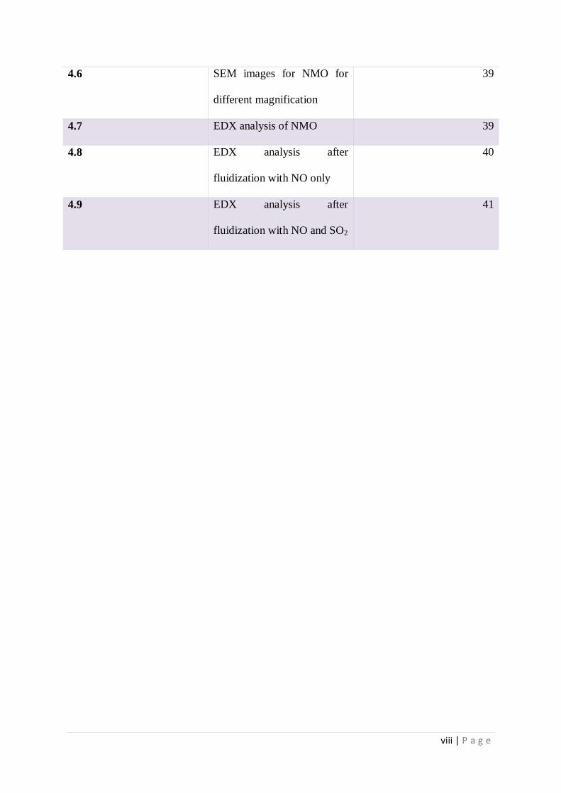
4.6 SEM images for NMO for
different magnification
39
4.7 EDX analysis of NMO 39
4.8 EDX analysis after
fluidization with NO only
40
4.9 EDX analysis after
fluidization with NO and SO2
41

ix | P a g e
ABSTRACT
In a Fluidized Bed Reactor, which can be operated till a maximum of 500ºC, abatement of
Oxides of Nitrogen needs to be done. The bed material chosen is manganese ore. The main
fluidizing gas is compressed air and the oxides of nitrogen are fed as the secondary fluidizing
fluid. The oxides of nitrogen are prepared in the laboratory itself. Along with the oxides of
nitrogen, sulphur dioxide is also fed as the secondary gas for some of the experiments to
check its effect on the abatement of oxides of nitrogen. Other than that temperature is also
varied to see its effect. The residence time is another factor on which quality of fluidization
depends hence it is also varied to check its effect on the abatement of oxides of nitrogen.
Finally the characterization of the bed material before and after fluidization is done and
compared to confirm the reduction in the quantity of oxides of nitrogen from what is initially
fed to the Fluidized Bed Reactor.

1 | P a g e
CHAPTER 1
INTRODUCTION

2 | P a g e
Introduction 1.1 Abatement of Oxides of Nitrogen (NOx)
There has been an enormous expansion in the emission of oxides of Nitrogen due to
agricultural fertilization and industrial emissions. Nitric oxide (NO), nitrogen dioxide (NO2),
and nitrous oxide (N2O) are included in the oxides of Nitrogen (NOx). Their lifespan in the
atmosphere ranges from 1 to 7 days for NO and NO2. NOx gasses are formed whenever
combustion occurs in presence of Nitrogen. Nitric Oxide is colourless, tasteless and odourless
and is non-toxic, but when in contact with air it rapidly gets converted to Nitrogen Dioxide.
NO2 is a reddish brown in colour and has a pungent irritating odour. Important component of
smog includes NO2
NOx emission contributes to the development of fine particles and ozone smog that
causes illness deaths and environment problems. NOx mainly impacts respiratory conditions
causing inflammation of airways, causing irritation, coughing and pain while taking deep
breaths. It can also cause inflammation, which is more like the burn caused on skin due to
sun. Asthma gets aggravated and vulnerability to respiratory illness like bronchitis and
pneumonia increases. Allergens response also gets aggravated by these oxides. Nitrate
particles and oxides of nitrogen reduces visibility by blocking the transmission of light.
Repeated exposures may also cause permanent damage or alterations in the lungs.
Also, these oxides can have adverse effects on both terrestrial and aquatic ecosystem.
It contributes to smog formation. It is ground level ozone. When NOx reacts with VOCs in
presence of sunlight and heat, smog is formed. VOCs are volatile organic carbon. People
who come in regular contact with this are susceptible to adverse effects such as reduction in
function of lungs and lung tissue getting damaged. Vegetation may get damaged which
causes the crop yield to reduce. Acid rain occurs due to the presence of these oxides in the

3 | P a g e
atmosphere. Its reaction with aerial substances forms acids, and it falls ion earth as rain, dry
particles, or fog. Acid rain causes deterioration and damage of buildings, historical
monuments and locomotives. Because of this water bodies becomes acidic, which makes it
inhabitable for aquatic animals. The chemical balance of nutrients which is used up by
animals and plants in water bodies gets upset by the presence of more nitrogen. These are
also greenhouse gasses, and causes a slow rise in the temperature of earth as it gets deposited
in the atmosphere along with other greenhouse gasses.
One of the newest technique for reducing the oxides of nitrogen in the atmosphere is
the Fluidized Bed method. This project targets on this very technology, to abate, from the flue
gas that comes out as gaseous effluents, the oxides of nitrogen.
1.2 Fluidised Bed Technology
Fluidization is a process similar to liquefaction and is the phenomenon in which solid particles get
transformed into a fluid like state through suspension in a liquid or gas. The bed particles behave
completely like fluids. As the thickness of the bed can be changed by changing the fluid part,
objects with diverse densities similar to the bed can, by modifying either the liquid or solid
fraction, be caused to sink or float. Fluidized bed is widely used in various industries. The
technology of Fluidized Bed has various advantages than other methods.
1.2.1 Advantages
The advantages of having a Fluidized Bed Reactor are:
It gives a good fluid-solid contact.
Under isothermal operating conditions it gives a very good rate of heat and mass transfer.

4 | P a g e
Circulation between two adjacent reactors is facilitated by the fluid like behaviour (for
example regeneration combination and catalytic cracking).
Maintenance cost is low as there is no part which moves, so the FBR is not a reactor which
is agitated mechanically.
The reactor saves space as it is mounted vertically. For a plant stationed at a place which
has high land cost this aspect is particularly important.
It is a continuous process, so can process large volumes of fluid. And it is coupled with
high throughput.
For reactions involving exothermic, heat sensitive or endothermic reactions, the fluidized
bed is particularly suitable.
Even for large scale operation, the system offers ease of control.
It can be used as heat exchangers with low surface area in the bed due to the high heat
transfer within the fluidized bed.
Multilevel operations are also possible. So the resistance time of the fluid and the residence
time of solids can be adjusted to desired levels.
1.2.2 Applications
Fluidized Bed Reactor has many industrial applications as can be seen in the above
mentioned advantages. It is used in metallurgy industry, nuclear power plants, petroleum,
chemical, and bio-chemical industries. Fluidized-Bed Catalytic Cracking (FCC) is widely
used and important process of refinery for converting less profitable, heavy oils into more
5 | P a g e
profitable gasoline and lighter products. In Petroleum industry, it is largely used for FCC, in
chemical operations like carbonization and gasification of coal, iron oxide reduction, sulhut
ore’s roasting, fertilizer’s granulation, granular material’s blending, combustion, incineration,
for formation plastic with the help of rubber, in the recovery of acetone, polyethylene’s
formation, to convert hydrocarbons to styrenes and in pyrolysis and in physical operations i.e.
solid’s drying such as that of minerals that are crushed, polymers, sand, crystalline products,
pharmaceuticals, and fertilizers, using plastic to coat metals and particles in agricultural and
pharmaceutical industries, for solid’s granulation and transportation, cooling and heating of
water and in treatment of waste etc. Fluidization’s commercial applications include cement
clinker production, reforming, FCC, aluminium hydroxide’s calcination, synthesis using
Fisher-Tropsch process, regeneration of catalyst , granulation (growing particles) and drying
of yeast, fluid coking, waste water treatment by bio-oxidation process, in solid’s
transportation like slurry pipeline for coal and in oxidation reactions involving solid catalyzed
gas phase reactions.
1.3 Objective of the Work
The objective of the present work is planned as follows:
To study the effect of various system parameters (temperature and residence time) on
the abatement of the oxides of nitrogen in the Fluidized Bed Reactor.
To analyse the bed material before and after the reaction.
To study the effect on fluidization on passage of sulphur dioxide as the reacting gas
with oxides of Nitrogen.

6 | P a g e
1.4 Thesis Layout
The thesis has five chapters.
1st Chapter: It describes the introduction to research work.
2nd
Chapter: It gives the comprehensive layout of the abatement techniques used in different
industries for the abatement of oxides of nitrogen (NOx). It then talks about the selection of
bed material and the details about the bed material and its uses.
3rd
Chapter: This highlights the experimental set-up, materials and methods used for the
abatement of oxides of nitrogen which has been prepared in the laboratory. It also gives the
complete procedure of how the oxides of nitrogen and sulphur dioxide were prepared in the
laboratory. This chapter also gives details about the fluidized bed reactor which was set up in
the laboratory and its various components.
4th
Chapter: The result obtained after the reaction are described in this chapter.
5th
Chapter: The fifth chapter deals with the conclusion that have been drawn on the work
done and also gives details about the scope of future work.

7 | P a g e
CHAPTER- 2
LITERATURE SURVEY
8 | P a g e
LITERATURE SURVEY
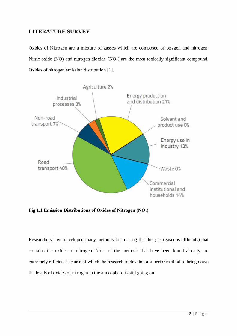
Oxides of Nitrogen are a mixture of gasses which are composed of oxygen and nitrogen.
Nitric oxide (NO) and nitrogen dioxide (NO2) are the most toxically significant compound.
Oxides of nitrogen emission distribution [1].
Fig 1.1 Emission Distributions of Oxides of Nitrogen (NOx)
Researchers have developed many methods for treating the flue gas (gaseous effluents) that
contains the oxides of nitrogen. None of the methods that have been found already are
extremely efficient because of which the research to develop a superior method to bring down
the levels of oxides of nitrogen in the atmosphere is still going on.

9 | P a g e
2.1. Different methods available for abatement of Oxides of Nitrogen
(NOx):
Various methods that are in used for abatement of oxides of Nitrogen. A summary of these
methods is given below:
2.1.1. Abatement with Hydrogen peroxide: For controlling NOx emissions several methods
are there. For the treatment of NOx, one of the most common form is gas scrubbing, with the
scrubbing medium being sodium hydroxide. But it may produce waste water disposal
problem as the NOx that is absorbed is converted to nitrate and nitrite. For effective removal
of NOx scrubbing solutions containing hydrogen peroxide are used, and can give advantages
not usable with sodium hydroxide. For example, to the scrubbing solution no contaminants
are added by hydrogen peroxide and hence from the process commercial products can be
recovered. Nitric acid is an example of such a product. Nitric oxide (NO) and nitrogen
dioxide (NO2), which are the chief components of oxides of nitrogen from any industrial
sources, are scrubbed by nitric acid (35-45 wt. %) and H2O2 (0.5-1 wt. %). 0.37 lbs and 1.7
lbs of hydrogen peroxide per lb of NO2 and NO are used. The reaction is fast when (30-80)ºC
range of temperature is maintained. The reactions are:
23NO + OH 2 32HNO + NO … Eq.1
NO2 + 3HNO + 22 3HNOOH … Eq.2
2HNO + 322 HNOOH + OH 2 … Eq.3

10 | P a g e
2.1.2 Selective Catalytic Reduction: At an appropriate temperature range of (200-400) °C,
this method involves the reaction of NO and NO2 (oxides of nitrogen-NOx ) with ammonia
gas (NH3) within a catalytic bed. The species in NOx reacts with ammonia (NH3), and several
reactions takes place. The dominant reactions are given below:
NO4 + 34NH + 22 4NO + OH 26 … Eq.4
26NO + 23 78 NNH + OH 212 … Eq.5
In the flue gas, NOx mainly contains nitrogen dioxide (NO2) although some amount of nitric
oxide (NO) is also present. Ammonia is chemically adsorbed on the catalyst’s active surface
sites, where from the gas phase NOx reacts. Many catalysts are available based on the
temperature window. Vanadium, molybdenum oxides, titanium and tungsten, which are
impregnated on ceramic or metallic substrate are the most common catalyst. TiO2 and V2O5
are generally used and sometimes small amounts of heavy metals like WO3 are added [1].
2.1.3. Selective Non-Catalytic Reduction: This process is also called thermal DeNOx. In this
at high temperature of (900-1000) ºC, reduction of NOx to N2 or takes place, in the flue gas,
by reaction with urea, (NH2)2CO, and ammonia (NH3). Since the process takes place at much
higher temperature, it doesn’t need any catalyst. The overall reaction is given as:-
22 NCONHH + OHCONONO 2222 22
12 … Eq.6
In functional application NH3 added substance is infused into the flue gas closer to the
combustion zone than in the SCR process. The effectiveness of the SNCR methodology relies
on upon a few elements including the NOx level, temperature, response time, reagent-vent
gas blending, and NH3/NOx proportion [1].

11 | P a g e
2.1.4. Fluidized Bed Method: Here, oxides of nitrogen existent in the flue gas are decreased
by passing the gas through a suitable bed material where the oxides of nitrogen are
catalytically adsorbed on the bed material. Based upon the achievement of a predetermined
bed expansion the beds can be switched and the process can be conducted in parallel units
connected by switching fluidized beds. For more reduction of oxides of nitrogen the process
can be done in continuous operation. And hence the oxides of nitrogen can be adsorbed
chemically on the surface of bed material or be reacted to form respective nitrates or nitrites.
Fluidized bed method is found to be more effective among the different methods used
for the abatement of oxides of nitrogen. It is due to better solid fluid contact and also due to
the numerous other benefits associated with the principle of fluidization. Solid metal particles
are required to be used in the bed, in this method.
In both the chemical reaction and physical processes, gas –solid fluidized beds have
been broadly utilized due to their superb gas–solid contacting and generally uniform
temperature/ concentration profiles inside the beds. Gas–solid circulating fluidized beds [2, 3]
find wide application in the chemical and process industries, such as fluidized catalytic
cracking (FCC) [4], combustion [5], alumina calcining [6], and synthesis of fine chemicals
like maleic anhydride [8]. More recently, liquid–solid circulating fluidized beds are also
finding applications in the process industries such as in the synthesis of aromatic and olefinic
alkylates [9, 10].
2.2. Manganese Ore as a Prospective Bed Material:
Most of the works of NOx and SO2 removal focuses on process either for SO2 removal or NOx
reduction only, very few for simultaneous reductions. Techniques have been developed for
simultaneous DeSOx/DeNOx and can be categorized into 2 groups’ namely: dry and wet
techniques. In aqueous solution solubility of nitric oxide is low. So, chemical scrubbings, as

12 | P a g e
wet method, can’t be used. In simultaneous dry removal process absorption for removal of
SOx and selective catalytic reduction for removal of NOx is considered to be a promising
process [11]. Natural Manganese Ore (NMO), which is composed of various metal oxides,
mainly manganese oxide, has the potential to be used as a sorbent catalyst in the simultaneous
removal of SOx/NOx and has good abrasion resistance. Also it is low cost and does not need
any kind of pre-treatment for its operation (other than crushing). The major equation involved
in adsorption of NO2 :
32 MnNONOMnO … Eq.7
2.3 Utilization of Manganese Ore
The uses of NMO are (i) In the extraction of Manganese metal. (ii) Removal of Arsenic from
gunpowder using low cost ferriginious manganese ore[11] (iii) Used in Chemical looping
combustion- Effect of steam gasification[12] (iv)to abate fluoride from water[13]. The NMO
can also be utilized for reducing NOx and SOx simultaneously.
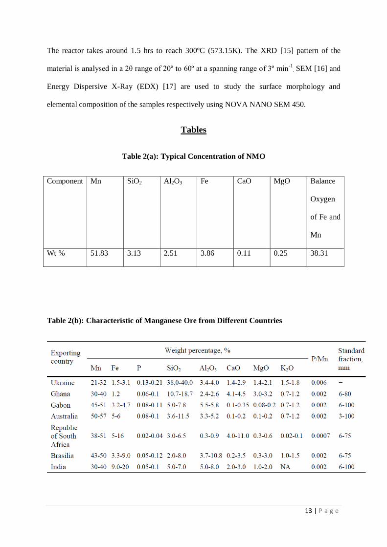
2.4 Composition of NMO
A typical manganese ore contains Mn, Si, Fe, Al, Ca, Mg, Zr, and etc. The typical
composition of NMO is given in table 2(a) [11]. The composition of manganese ore in
different countries is given in table 2(b) [14]. The typical properties of NMO are given in
table 2(c).
2.5 Material Characterization Technique
In order to understand NMO characteristics, when it is fluidized in the reactor, above the
minimum fluidization velocity various samples are collected at different temperatures- room
temperatures, 150ºC (423.15K), 200ºC (473.15K), 250ºC (523.15K) and 300ºC (573.15K).
13 | P a g e
The reactor takes around 1.5 hrs to reach 300ºC (573.15K). The XRD [15] pattern of the
material is analysed in a 2θ range of 20º to 60º at a spanning range of 3º min-1
. SEM [16] and
Energy Dispersive X-Ray (EDX) [17] are used to study the surface morphology and
elemental composition of the samples respectively using NOVA NANO SEM 450.
Tables
Table 2(a): Typical Concentration of NMO
Component Mn SiO2 Al2O3 Fe CaO MgO Balance
Oxygen
of Fe and
Mn
Wt % 51.83 3.13 2.51 3.86 0.11 0.25 38.31
Table 2(b): Characteristic of Manganese Ore from Different Countries

14 | P a g e
Table 2(c): Physical Properties of NMO
Physical Property Value
Density(gcm-3
) 3.98
Surface Area(m2g
-1) 20
Pore Volume(cm3g
-1) 0.0392(5-3000Å)
Average Pore Diameter(Å) 134.36

15 | P a g e
CHAPTER 3
EXPERIMENTATION

16 | P a g e
EXPERIMENTATION
The manganese ore which was brought from a local supplier. First the NMO brought are to
be reduced to the particle size which can be fluidized. Then the preliminary experiments are
carried out using a Perspex column which has the same dimension inside which the actual
reaction is intended to take place (Fig 3.1). The minimum fluidization velocity obtained at a
particular flow rate is noted. Hence we now can carry the experiment in the actual fluidized
bed at a much higher temperature, using the min fluidization velocity in the Perspex column.
In the laboratory a stainless steel made Fluidized Bed Reactor has been designed. NMO of
definite size is selected as bed material and the change which occurs at the high temperatures
are studied. After that two sets of experiments were carried out where the laboratory prepared
nitric oxide and nitrogen dioxide were allowed to mix with the fluidizing gas there by
fluidizing the bed material. In the first case only oxides of nitrogen (with ammonia as
catalyst) are used as the fluidizing gas whereas in the second case oxides of sulphur (Sulphur
Dioxide-SO2) is also mixed. (SO2 is also prepared in the laboratory). The bed materials are
fluidized using a compressor.
3.1 Experimental Set-Up
The different components of the experimental set-up is shown by Fig 3.2(a-h) and schematic
diagram of the experimental set-up is shown in Fig 3.3. The compressor at a maximum
pressure of 2 kg is used to fluidize the bed material. The reactor and the pipes used to build
up the FBR is made up of Stainless Steel 316 grade and is fabricated with the help of
Mechmomine Kolkata and is able to withstand pressures till 5 atm (506625 Pa). The length of
the reactor column in 20.5” (0.5207m) and the internal diameter is 4” (0.1016m) with 0.39”
(0.009906 m) thickness. The reactor is bounded in both the sides with cones of 4” (0.1016m)
height and 4” (0.1016m) internal diameter, the thickness being same as the reactor column.
17 | P a g e
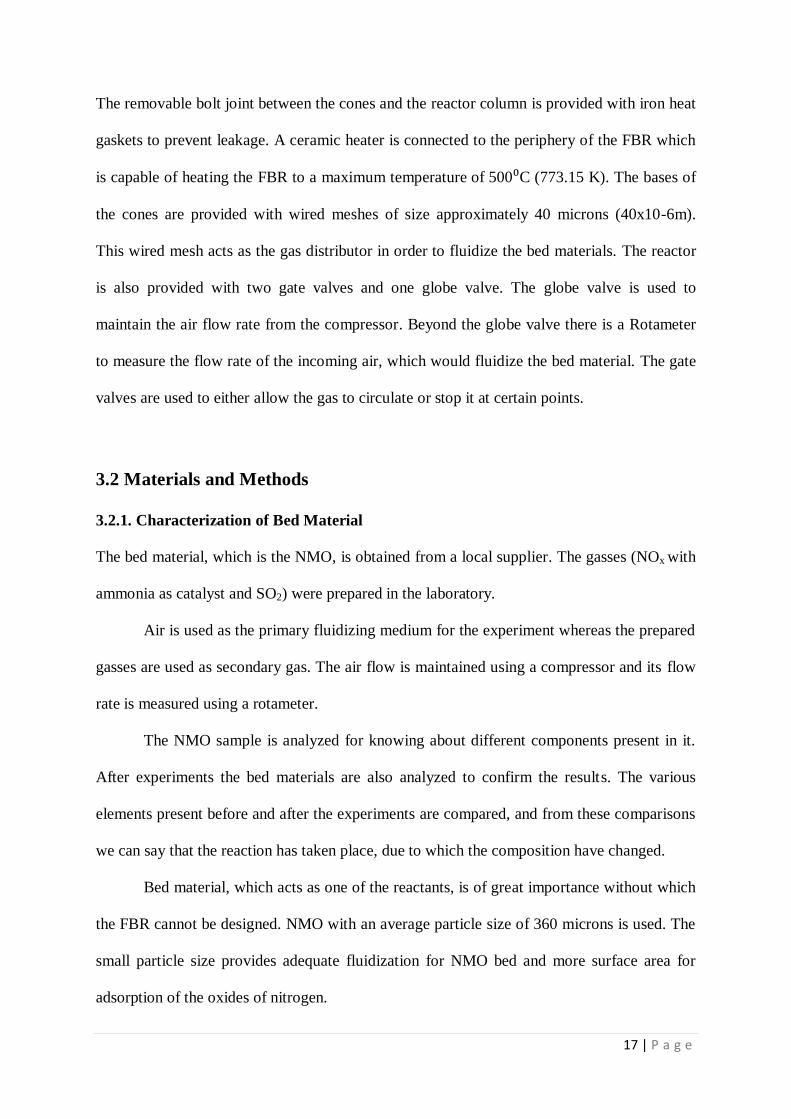
The removable bolt joint between the cones and the reactor column is provided with iron heat
gaskets to prevent leakage. A ceramic heater is connected to the periphery of the FBR which
is capable of heating the FBR to a maximum temperature of 500⁰C (773.15 K). The bases of
the cones are provided with wired meshes of size approximately 40 microns (40x10-6m).
This wired mesh acts as the gas distributor in order to fluidize the bed materials. The reactor
is also provided with two gate valves and one globe valve. The globe valve is used to
maintain the air flow rate from the compressor. Beyond the globe valve there is a Rotameter
to measure the flow rate of the incoming air, which would fluidize the bed material. The gate
valves are used to either allow the gas to circulate or stop it at certain points.
3.2 Materials and Methods
3.2.1. Characterization of Bed Material
The bed material, which is the NMO, is obtained from a local supplier. The gasses (NOx with
ammonia as catalyst and SO2) were prepared in the laboratory.
Air is used as the primary fluidizing medium for the experiment whereas the prepared
gasses are used as secondary gas. The air flow is maintained using a compressor and its flow
rate is measured using a rotameter.
The NMO sample is analyzed for knowing about different components present in it.
After experiments the bed materials are also analyzed to confirm the results. The various
elements present before and after the experiments are compared, and from these comparisons
we can say that the reaction has taken place, due to which the composition have changed.
Bed material, which acts as one of the reactants, is of great importance without which
the FBR cannot be designed. NMO with an average particle size of 360 microns is used. The
small particle size provides adequate fluidization for NMO bed and more surface area for
adsorption of the oxides of nitrogen.

18 | P a g e
3.2.2 Material Preparation
The NMO which was brought in form of large stones needs to be made to powdered form for
it to be used as a bed material for fluidization process. Other than the particle size, density
plays the major role in deciding the fluidization characteristic. Hence the density of the NMO
was first calculated. The density was calculated by water displacement method. The
procedure is as follows:
Beaker was filled with water up to its brim.
The amount of solid was weighed before immersing in the liquid.
Solid was then put inside the beaker.
The displaced water was collected in a tray.
The displaced liquid was taken in a measuring cylinder to measure its volume
Density was then calculated by: Density = Mass/Volume.
The density calculation observation are given in table 3(a). The average value of density
comes to be 3.384 gm.cm-3
. Now since the density comes to be 3.384 gm.cm-3
- it can be a
Geldart B or Geldart D particle. Since Geldart D particle are not suitable for fluidization (it
may cause spouting, unequal mixing etc.), we need to make the bed material a Geldart B
particle. The size should be between 40 to 500 microns.
The reduction of size takes place in two steps:
1. Crushing- The solid manganese ore which is in the form of large stones are crushed
initially to make it smaller so that it can be grinded to make it a powder. The crusher
used is Jaw crusher.
2. Grinding- The reduced size of the particles needs to be grinded to get to the required
size (40-500 microns). A ball mill was used for this purpose. In each run 30 balls of
equal size are used and ball mill is run for 30 to 40 minutes in a single run. The
repeated runs brought the size of the particles to required size range.

19 | P a g e
The powdered material obtained is then sieved to get the exact size range. A sieve-shaker is
used for separating the particles according to their mesh sizes. It was observed that the
maximum amount of particles were found in the range of 220 to 500 microns. So this size of
particle is taken for the fluidization purpose.
3.2.3 Voidage Calculation and Calculation of Min Fluidization Velocity
For calculating the min. fluidization velocity from theory as well from the experimental set-
up. Although the value calculated from experimental set up is to be used it will be useful to
compare the results when we calculate theoretically. To calculate theoretically we need to
have the value of voidage. The procedure for calculation of voidage is:
Weigh a mass of bed material
Put that mass of bed material inside the fluidized bed and calculate its volume.
From the equation mass = actual vol x density we can calculate the voidage
The observations and results are given in table 3(b).
From table 3(b) the value of voidage comes out to be 0.619. Now from Ergun’s equation min.
fluidization velocity comes to be 0.057 m/s.
3.2.4 Preparation of Gasses
The gasses used in the experiments are nitric oxide (NO), ammonia as catalyst (NH3) and
sulphur dioxide (SO2). The experimental set-up is given in Fig 3.4. The preparation technique
for all three are given below:
3.2.4.1. Preparation of Nitric Oxide
Nitric Oxide is readily oxidized to Nitrogen dioxide when it comes in contact with air. This
experiment was conducted in a well-ventilated area. The procedure for the process is
Dilute ferrous sulphate solution was put in a round bottom flask.
This solution was then acidified using dil sulphuric acid.
The above solution was well mixed.

20 | P a g e
Conc Sodium Nitrite solution was then added and on adding the solution turns dark
brown due to the formation of nitroso ferrous sulphate.
It was then heated in an electrical heater.
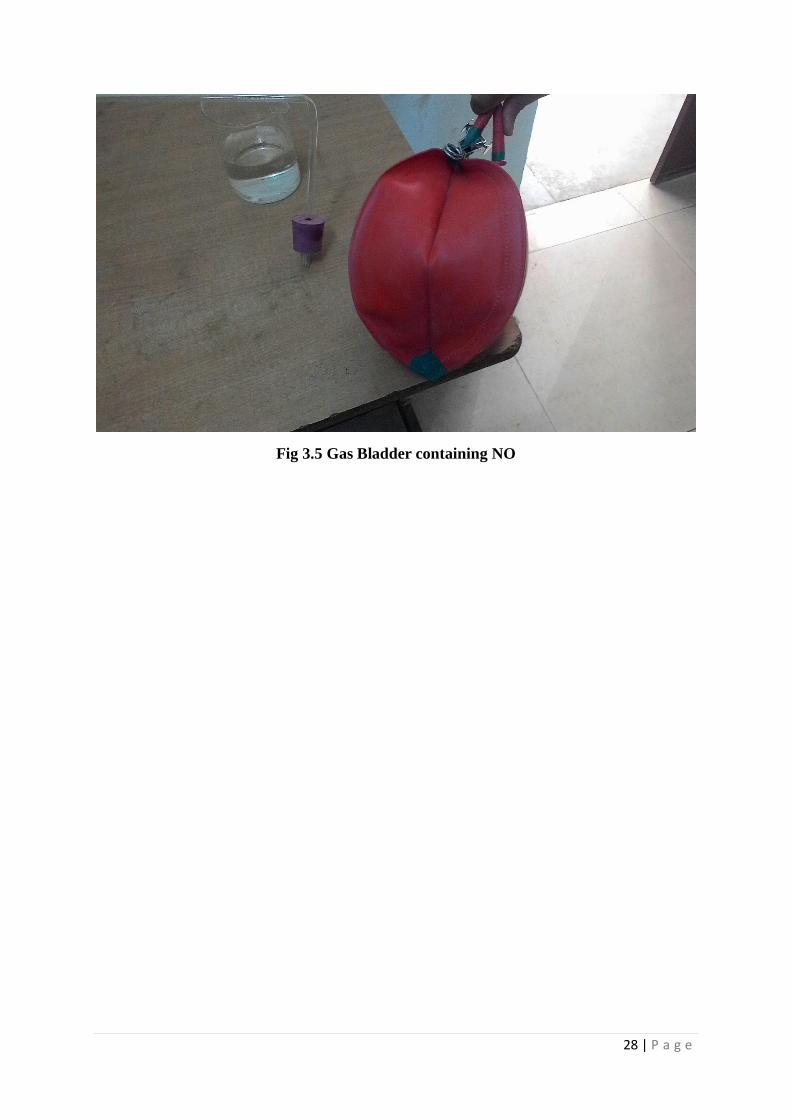
This nitroso ferrous sulphate on heating produces nitric oxide which was collected in
bladder. (Fig 3.5)
The overall equation for the above process is:
NOOHNaHSOSOFeSOHFeSONaNO 222)(322 24344242 … Eq. 8
3.2.4.2. Preparation of Sulphur Dioxide
Copper turnings when heated with conc sulphuric acid gives out sulphur dioxide. The
procedure for the process is:
A known and weighed amount of copper turning was put in a round bottom flask.
Conc sulphuric acid was then added to it.
Heat was supplied through an electric heater.
The produced SO2 was collected in a bladder through the upward displacement of air.
The bladder was secured using a pinch cork. (Fig 3.5)
3.2.5. Methods:
First the NMO was fluidized for 2 hours in the Perspex column to remove the easily
breakable part to prevent the change in average particle size. In the Perspex (Fig 3.2) column
preliminary experiments were carried out to understand the bed behavior when the bed was
allowed to fluidize with atmospheric air. Depending on the observations from Perspex
column experiments, same amount of NMO is then fed into the Stainless Steel column to
study the effect of temperatures when the NMO was allowed to fluidize. Various
characterization were also carried out on the NMO to support it. Depending on the results
obtained, two more experiments were carried out where the oxides of nitrogen (with
21 | P a g e
ammonia as the catalyst), in the first case, and sulphur dioxide (along with NOx and ammonia
as the catalyst), in the second case was used as the secondary gas.
In the first experiment 500 grams of NMO (320x10-6
) was fluidized with a mixture of
air and NO produced in the laboratory. Ammonia was also added with NO and is used as a
catalyst in the reaction. The air was supplied by the compressor and NO and NH3 were
supplied through gas bladder. In the bladder the prepared gasses from the laboratory were
stored. The bed was allowed to run at 200 ºC with a residence time of 30 minutes. The bed
material was collected after 30 minutes and characterization was done. The temperature was
then increased to 300ºC and a residence time was fixed at 30 minutes. The bed material was
then collected and characterization was again done.
In the second experiment 500 grams of NMO (320x10-6
) was fluidized with a mixture
of air, NO with ammonia as catalyst and sulphur dioxide (SO2). SO2 was also supplied in gas
bladder, prepared from the laboratory. The bed material was collected after a residence time
of 15, 30 and 45 minutes. After that the characterization of the bed material was done. The
similar procedure as the first experiment was carried out.

22 | P a g e
TABLES
Table No 3(a): Density Calculation of NMO.
RUN NO WEIGHT OF
THE ORE (gm)
VOLUME
DISPLACED
(ml)
DENSITY
(gm.cm-3
)
AVERAGE
DENSITY
(gm.cm-3
)
1. 250.410 74 3.384
3.36 2. 300.02 88 3.41
3. 275.56 82 3.36
Table No. 3(b): Voidage Calculation of bed material
Mass
Taken
(m) (gm)
Circumference
of FBR = 2 x
3.14 x r (cm)
Radius of
FBR (r)
(cm)
Height
of
fluidiz
ed bed
(cm)
Area of Cross
Section
(A)=3.14 x r2
(cm2)
Density
(gm/cm3)
Voidage =
1-(m/A x h x D)
500 31.25 4.97 5 77.71 3.384 0.619

23 | P a g e
Figures
(a)Non-Fluidized State (b) Fluidized State
Fig. 3.1 Perspex Fluidized Bed

24 | P a g e

25 | P a g e
(g) Compressor

26 | P a g e
(h) Experimental Set-up
Fig 3.2 Different Parts of the Fluidized Bed reactor
Fig 3.3 Schematic Diagram of the Experimental Set Up

27 | P a g e
(a)At the start of the reaction
(b) After some time
Fig 3.4 Experimental Set-up for the Production of NO and SO2
28 | P a g e
Fig 3.5 Gas Bladder containing NO

29 | P a g e
CHAPTER 4
OBSERVATION AND RESULTS

30 | P a g e
OBSERVATION AND RESULT
4.1 Analysis for Manganese Ore as bed material with or without flue gas
treatment.
Preliminary study regarding the bed material and its characterization is very important to
carry out the experiment. As literature indicates the oxides of nitrogen will get adsorbed with
the metal particles at high temperature, it is essential to know the characteristic of NMO at
different temperatures for the present work. Depending on the results obtained from
preliminary characterization of NMO, the further reactions in the fluidized bed are carried out
accordingly.
4.1.1 Fluidization Parameter
Fluidization is one of the best methods of providing proper fluid-solid contact. Different
aspects affect the quality of fluidization. Again many aspects are to be analyzed as
prerequisites for proper fluidization. Minimum fluidization velocity is one of the aspects
which is to be determined first. Preliminary experiments suggests that NMO particles of 320
microns size have good fluidization quality and is used as a bed material for the reaction. The
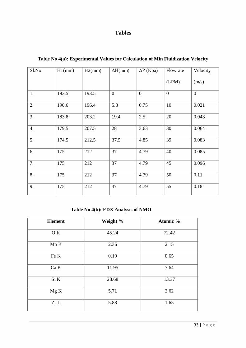
theoretical value of the minimum fluidization velocity comes to be 0.057 m/s. From the
experimental data for finding min fluidization velocity (Table 4(a)) a graph was plotted
between ΔP (Kpa) and u (m/s) –Fig 4.1 and the minimum fluidization velocity was found to
be 0.085 m/s. It is almost same as the theoretical value.
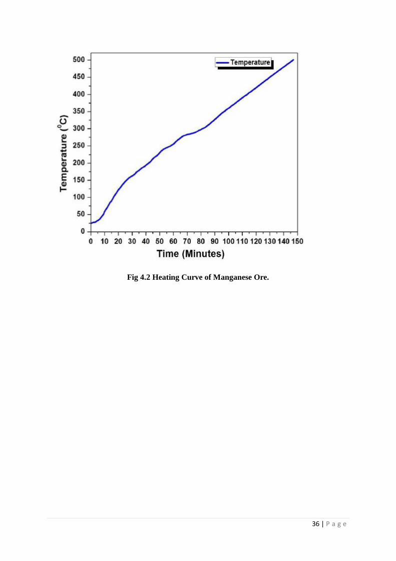
4.1.2. Heating Process
Fig 4.2 indicates the time taken by the FBR to reach the maximum temperature of 500⁰C
(773.15K). The reactor takes almost 42 minutes to attain a temperature of 200⁰C
(473.15K), 58 minutes to reach 250⁰C (523.15K) and 93 minutes to reach 300⁰C (573.15K).

31 | P a g e
4.1.3 XRD Analysis
Various researchers have studied the phase characterization and elemental analysis of NMO
but the data analysis for the composition of NMO are found to be non-uniform because of its
variation in elemental composition at different places. The XRD patterns of NMO are
observed and are shown in Fig 4.3. The major components at room temperature are
manganese (Mn), Manganese Oxide (MnO2), silicon dioxide (SiO2), Calcium Oxide (CaO),
Iron (Fe), Aluminium Oxide (Al2O3), and Magnesium Oxide (MgO). The XRD pattern of the
elements are referred form JCPDS file of X’Pert HighScore software. Using peak broadening
technique of X’Pert High Score software for XRD analysis, one can clearly differentiate the
peaks. The Peaks of Mn are coming at around 28.68º, 37.33º and 56.65º. There are no traces
of any Manganese nitrate from the XRD analysis.
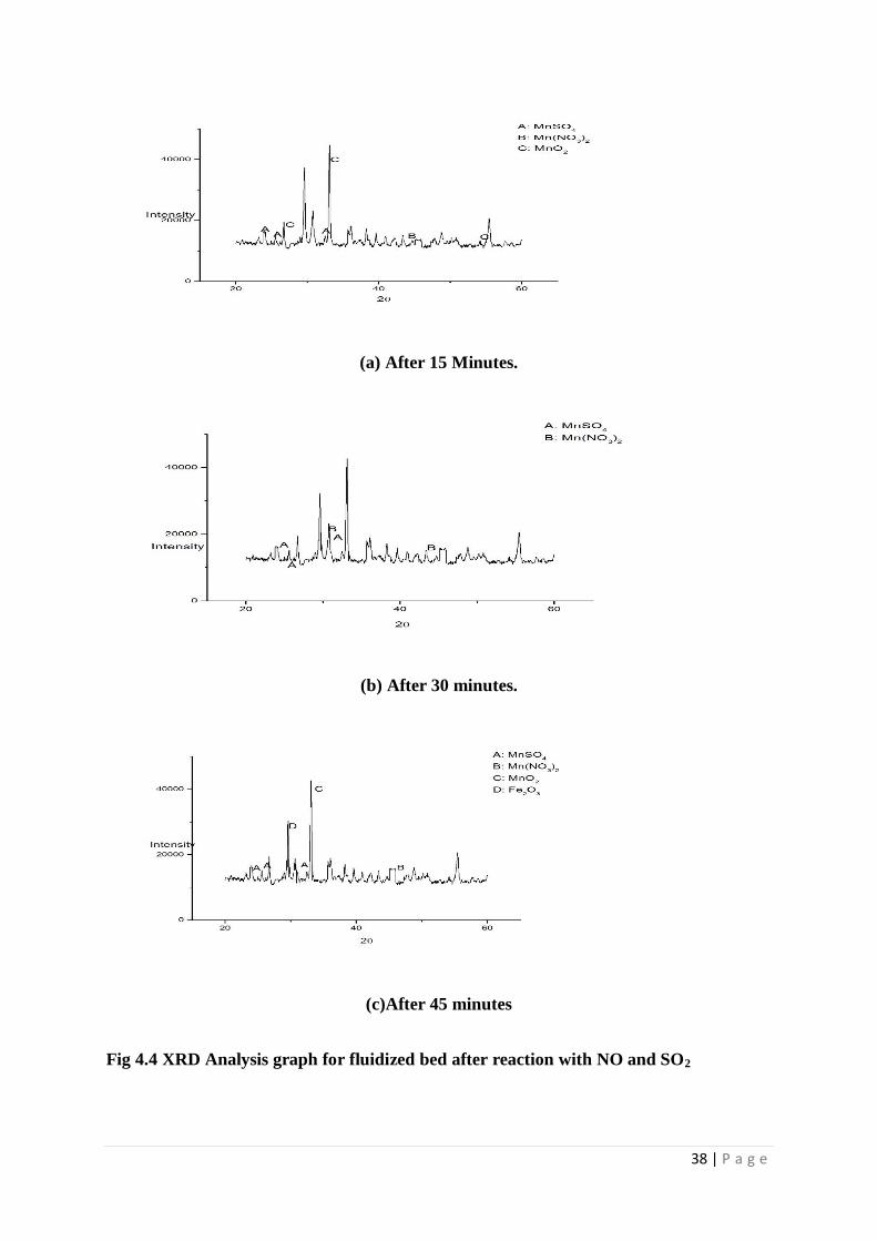
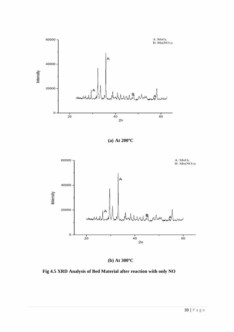
After the reaction has taken place the bed material was again analyzed. First, the
analysis was done after 15 minutes at a temperature of 200ºC. The gasses passed are nitric
oxide, ammonia and sulphur dioxide. There are peaks for Manganese Nitrate found which
proves that NO is being absorbed (Fig 4.4a). The bed material was again analyzed after 30
minutes (Fig 4.4b) and 45 minutes (Fig 4.4c). The peaks for the nitrate and sulphate are both
found in all the three cases. Next the analysis was done after passing only nitric oxide and
ammonia with the fluidizing gas. This time the residence time was taken to be 30 minutes.
Here also a peak for manganese nitrate was found (Fig 4.5a). The temperature was then
increased to 300ºC. The residence time was taken to be 30 minutes again (Fig 4.5b). Again
only nitric oxide and ammonia were passed and SO2 was not passed. The peak for manganese
nitrate was again found. Hence we can be sure that the nitric oxide was adsorbed on the
surface of Manganese ore.

32 | P a g e
4.1.4 SEM and EDX Analysis
To analyze the morphological structure of the sample SEM is done. The SEM images of
NMO before and after the reaction are given in Fig 4.6(a-c). The EDX analysis gives the idea
about the composition of different elements in the bed material. As expected we do not see
any sulphur or nitrogen present. Oxygen is present in the highest quantity, followed by
Manganese (table 4(b)). The graph of the different concentration of bed material is also given
(Fig 4.7).
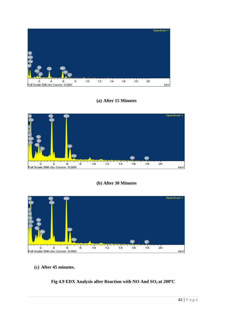
SEM of the particle after the experiments are carried out are also done. The EDX
results for the first experiment (at 200ºC and 300ºC) are also plotted in Fig 4.7 and its
respective elemental analysis in tabular form is given in table 4(c). Similarly for the second
experiment for all the residence time the EDX results are plotted in Fig 4.8 and elemental
analysis is done in table 4(d).
33 | P a g e
Tables
Table No 4(a): Experimental Values for Calculation of Min Fluidization Velocity
Sl.No. H1(mm) H2(mm) ΔH(mm) ΔP (Kpa) Flowrate
(LPM)
Velocity
(m/s)
1. 193.5 193.5 0 0 0 0
2. 190.6 196.4 5.8 0.75 10 0.021
3. 183.8 203.2 19.4 2.5 20 0.043
4. 179.5 207.5 28 3.63 30 0.064
5. 174.5 212.5 37.5 4.85 39 0.083
6. 175 212 37 4.79 40 0.085
7. 175 212 37 4.79 45 0.096
8. 175 212 37 4.79 50 0.11
9. 175 212 37 4.79 55 0.18
Table No 4(b): EDX Analysis of NMO
Element Weight % Atomic %
O K 45.24 72.42
Mn K 2.36 2.15
Fe K 0.19 0.65
Ca K 11.95 7.64
Si K 28.68 13.37
Mg K 5.71 2.62
Zr L 5.88 1.65

34 | P a g e
Table No 4(c): EDX Analysis after reaction at 200ºC (only NO and NH3).
Element Weight % Atomic %
O K 45.24 72.42
Mn K 2.36 2.15
Fe K 0.19 0.15
Ca K 11.95 7.64
Si K 28.68 13.37
N K 4.23 2.23
Zr L 5.88 1.65
Table No 4(d): EDX Analysis after reaction at 200ºC (NO + NH3 + SO2) after 15
minutes.
Element Weight % Atomic %
O K 43.00 52.04
Mn K 25.10 25.87
Si K 21.07 19.02
Al K 0.14 0.07
N K 0.41 0.21
S K 0.04 0.02
K K 0.12 0.05
Ca K 2.46 0.89
Mg K 5.24 1.38
Fe K 1.23 0.32
Zr L 0.88 0.14

35 | P a g e
FIGURES
Fig 4.1 Pressure Drop Vs Velocity Plot for Bed Material (Manganese Ore) of 320
microns
36 | P a g e
Fig 4.2 Heating Curve of Manganese Ore.

37 | P a g e
Fig 4.3 XRD Analysis of Natural Manganese Ore.
38 | P a g e
(a) After 15 Minutes.
(b) After 30 minutes.
(c)After 45 minutes
Fig 4.4 XRD Analysis graph for fluidized bed after reaction with NO and SO2
39 | P a g e
(a) At 200ºC
(b) At 300ºC
Fig 4.5 XRD Analysis of Bed Material after reaction with only NO

40 | P a g e
(a) At magnification 1000 (b) At magnification 2500
(c) At magnification 5000
Fig 4.6 SEM Images for Manganese Ore
Fig 4.7 EDX Analysis of Natural Manganese Ore

41 | P a g e
(a) At 200ºC
(b) At 300ºC
Fig 4.8 EDX Analysis after fluidization with NO only
42 | P a g e
(a) After 15 Minutes
(b) After 30 Minutes
(c) After 45 minutes.
Fig 4.9 EDX Analysis after Reaction with NO And SO2 at 200ºC

43 | P a g e
Chapter 5
Conclusion

44 | P a g e
Conclusion
5.1 Conclusion
Two sets of experiments were carried out. One with nitric oxide (NO) and (NH3) are mixed
with fluidizing gas (compressed air). This experiment was carried out at two temperature
condition-one at 200ºC and other one at 300ºC. From the XRD analysis we can confirm the
formation of Manganese Nitrate which forms due to the chemical adsorption of NO2 on
MnO2. Here NH3 acts as a catalyst and does not take part in the reaction. Although exact
concentration of Manganese Nitrate could not be determined but through EDX analysis it was
found that for the same residence time (30 minutes) concentration of Nitrogen element in the
bed is more. Hence on increase of temperature the chemical adsorption of oxides of nitrogen
increases. Also beyond 300ºC, from theory we know that ammonia decomposes, hence above
300ºC experiments were not carried out.
In the second set of experiments, sulphur dioxide was also passed along with the
oxides of nitrogen and ammonia. From the XRD it showed that manganese nitrate was still
being formed, hence the adsorption of NO on the surface of the ore was still taking place.
From the EDX analysis for 30 minutes residence time it was seen the amount of nitrogen
content was more in this case. It implies that more amount of NO is adsorbed in presence of
SO2. This might be due to the fact that it is acidic in nature and promotes the adsorption of
NO on the surface of the ore. Now if we compare the nitrogen concentration for different
residence time we find that from 15 minutes to 30 minutes the nitrogen concentration
increases rapidly. But from 30 minutes to 45 minutes there is no rapid increase of
concentration of nitrogen. This might be due to the fact that SO2 is also adsorbed on the
surface of the ore and it forms sulphates. These sulphates reduces the pore size, hence
reducing surface area. With decrease in surface area NO adsorption also decreases.

45 | P a g e
Hence this process can be easily used in industries as it helps in the reduction of two harmful
gasses and scale up of the reactor can be done.
5.2 Scope and Future Work
To study the usage of bed materials. The bed material, if converted to something
useful, can become a boon for the industries.
By sampling the gas exact results can be achieved.
To study the various kinetics occurring in FBR leading to a better understanding and
control of reactors
Making the process more effective by minimizing leakage and by providing proper
insulation.

46 | P a g e
ABBREVIATIONS:
FBR: Fluidized Bed Reactor
NMO: Natural Manganese Ore
XRD: X-Ray Diffraction
SEM: Scanning Electron Microscope
EDX: Energy Dispersive X-Ray

47 | P a g e
REFERENCES
1. Nitrogen Oxides | NOx Abatement | H2O2 | H2O2.com – USPeroxide
2. Radojevic, M. “Reduction of Nitrogen Oxide in Flue Gasses” Elsevier, 102, 686,
1998.
3. Reh, L. and Basu, P. ŽEd. “Circulating Fluidized Bed Technology.” Pergamon, New
York.105, 543, 1986;
4. Ensgtrom, F.; Lee,Y.Y.; Basu, P.; Horio, M. and Hasatani, M. ŽEds, “Circulating
Fluidized Bed Technology III”. Pergamon, NY. 15, 182, 1991.
5. Metso Automation Inc. Application report on Fluid Catalytic Cracking Unit,
2721/07/01, 2011.
6. Joris, K.; Martin, J. and André F. “Development of fluidized bed combustion—An
overview of trends, performance and cost.” 76, 102, 2007;
7. Heath, T.; Jukkola, W; Lewis, R.; Malabre, L. and Smith D. “Process of calcining
alumina trihydrate in fluidized bed.” US Patent No.# 2799558 A; 1957
8. Renshui L. “V-P-Si composite oxide catalyst precursor used for producing maleic
anhydride from butance.” US Patent No # 7547655 B2; 2009.
9. Vipin, V.; Paul,S. and Cottrell, L. “Process for the production of alkylaromatic
hydrocarbons using solid catalysts.” US Patent No.# 5012021 A; 1991.
10. Dennis, J.; Rear, O.; Steven, S.; Thomas, V.; Curtis, L.and Cong, C. “Preparation of
high octane alkylate from Fischer-Tropsch Olefins.” US Patent No.# 6743962 B2;
2004.
11. Jeong, K.S. ; Park, T.S. and Hong S.C. “Simultaneous Removal of SOx/NOx in a
fluidized bed reactor using Natural Manganese Ore” Journal of Chemical Technology
and Biotechnology 76, 1080, 2001.
12. Chkravarty, S.; Dureja, V.; Bhattacharya, G.; Maity, S. and Bhattacharjee , S.
“Removal of arsenic from gunpowder using low cost Manganese ore” Elsevier, 36, 3,
2002
13. Arjmand, M.; Leion, H.; Mattison T. and Lyngfelt A. “Use of Manganese Ore in
Chemical-Looping Combustion (CLC)-Effect on Steam Gassification” Elsevier, 8, 56,
2012.
14. Mohapatra, D.; Mishra, D.; Mishra, S.P. and Choudhury G..Roy., “Use of Oxide
Minerals to abate fluoride from water” Elsevier, 275, 355, 2004.

48 | P a g e
15. Loye, Hanno zur. “X Ray Diffraction- How it works” Bicentennial, 2, 34, 1987.
16. Todokoro, H. and Otaka, T. “Scanning Electron Microscope” US5389787 A; 1995
17. Hafner, B. “EDX on SEM: A Primer” Elsevier, 256, 1, 2000.
18. Nath, H.; Sahoo, P. and Sahoo, A. “Characterization of Red Mud under High
Temperature Fluidization” Elsevier, 269, 234, 2015.